EP3077136B1 - Anlage zur herstellung von bewehrungskörben für turmsegmente von windenergieanlagen - Google Patents
Anlage zur herstellung von bewehrungskörben für turmsegmente von windenergieanlagen Download PDFInfo
- Publication number
- EP3077136B1 EP3077136B1 EP14786489.6A EP14786489A EP3077136B1 EP 3077136 B1 EP3077136 B1 EP 3077136B1 EP 14786489 A EP14786489 A EP 14786489A EP 3077136 B1 EP3077136 B1 EP 3077136B1
- Authority
- EP
- European Patent Office
- Prior art keywords
- elements
- handling robot
- stiffening
- stiffening elements
- handling
- Prior art date
- Legal status (The legal status is an assumption and is not a legal conclusion. Google has not performed a legal analysis and makes no representation as to the accuracy of the status listed.)
- Active
Links
- 230000002787 reinforcement Effects 0.000 title description 12
- 238000009434 installation Methods 0.000 title description 3
- 230000003014 reinforcing effect Effects 0.000 claims description 25
- 230000008878 coupling Effects 0.000 claims description 22
- 238000010168 coupling process Methods 0.000 claims description 22
- 238000005859 coupling reaction Methods 0.000 claims description 22
- 238000005452 bending Methods 0.000 claims description 21
- 239000000463 material Substances 0.000 claims description 21
- 238000004804 winding Methods 0.000 claims description 9
- 238000003466 welding Methods 0.000 claims description 6
- 229910000831 Steel Inorganic materials 0.000 claims description 4
- 239000010959 steel Substances 0.000 claims description 4
- 239000002184 metal Substances 0.000 claims description 3
- 239000000853 adhesive Substances 0.000 claims description 2
- 230000001070 adhesive effect Effects 0.000 claims description 2
- 238000005476 soldering Methods 0.000 claims description 2
- 238000003892 spreading Methods 0.000 claims description 2
- 230000001419 dependent effect Effects 0.000 claims 3
- 241000237519 Bivalvia Species 0.000 claims 1
- 235000020639 clam Nutrition 0.000 claims 1
- 238000004519 manufacturing process Methods 0.000 description 11
- 239000000109 continuous material Substances 0.000 description 9
- 238000003860 storage Methods 0.000 description 9
- 229910001294 Reinforcing steel Inorganic materials 0.000 description 4
- 238000006243 chemical reaction Methods 0.000 description 2
- 239000004567 concrete Substances 0.000 description 2
- 238000000034 method Methods 0.000 description 2
- 239000004237 Ponceau 6R Substances 0.000 description 1
- 230000001133 acceleration Effects 0.000 description 1
- 238000010276 construction Methods 0.000 description 1
- NJPPVKZQTLUDBO-UHFFFAOYSA-N novaluron Chemical compound C1=C(Cl)C(OC(F)(F)C(OC(F)(F)F)F)=CC=C1NC(=O)NC(=O)C1=C(F)C=CC=C1F NJPPVKZQTLUDBO-UHFFFAOYSA-N 0.000 description 1
- 239000011150 reinforced concrete Substances 0.000 description 1
- 230000000087 stabilizing effect Effects 0.000 description 1
Images


Classifications
-
- B—PERFORMING OPERATIONS; TRANSPORTING
- B21—MECHANICAL METAL-WORKING WITHOUT ESSENTIALLY REMOVING MATERIAL; PUNCHING METAL
- B21F—WORKING OR PROCESSING OF METAL WIRE
- B21F23/00—Feeding wire in wire-working machines or apparatus
-
- E—FIXED CONSTRUCTIONS
- E04—BUILDING
- E04C—STRUCTURAL ELEMENTS; BUILDING MATERIALS
- E04C5/00—Reinforcing elements, e.g. for concrete; Auxiliary elements therefor
- E04C5/01—Reinforcing elements of metal, e.g. with non-structural coatings
- E04C5/06—Reinforcing elements of metal, e.g. with non-structural coatings of high bending resistance, i.e. of essentially three-dimensional extent, e.g. lattice girders
- E04C5/0604—Prismatic or cylindrical reinforcement cages composed of longitudinal bars and open or closed stirrup rods
- E04C5/0609—Closed cages composed of two or more coacting cage parts, e.g. transversally hinged or nested parts
-
- B—PERFORMING OPERATIONS; TRANSPORTING
- B21—MECHANICAL METAL-WORKING WITHOUT ESSENTIALLY REMOVING MATERIAL; PUNCHING METAL
- B21F—WORKING OR PROCESSING OF METAL WIRE
- B21F27/00—Making wire network, i.e. wire nets
- B21F27/08—Making wire network, i.e. wire nets with additional connecting elements or material at crossings
- B21F27/10—Making wire network, i.e. wire nets with additional connecting elements or material at crossings with soldered or welded crossings
-
- B—PERFORMING OPERATIONS; TRANSPORTING
- B21—MECHANICAL METAL-WORKING WITHOUT ESSENTIALLY REMOVING MATERIAL; PUNCHING METAL
- B21F—WORKING OR PROCESSING OF METAL WIRE
- B21F27/00—Making wire network, i.e. wire nets
- B21F27/12—Making special types or portions of network by methods or means specially adapted therefor
- B21F27/121—Making special types or portions of network by methods or means specially adapted therefor of tubular form, e.g. as reinforcements for pipes or pillars
- B21F27/122—Making special types or portions of network by methods or means specially adapted therefor of tubular form, e.g. as reinforcements for pipes or pillars by attaching a continuous stirrup to longitudinal wires
- B21F27/124—Making special types or portions of network by methods or means specially adapted therefor of tubular form, e.g. as reinforcements for pipes or pillars by attaching a continuous stirrup to longitudinal wires applied by rotation
-
- B—PERFORMING OPERATIONS; TRANSPORTING
- B21—MECHANICAL METAL-WORKING WITHOUT ESSENTIALLY REMOVING MATERIAL; PUNCHING METAL
- B21F—WORKING OR PROCESSING OF METAL WIRE
- B21F27/00—Making wire network, i.e. wire nets
- B21F27/12—Making special types or portions of network by methods or means specially adapted therefor
- B21F27/121—Making special types or portions of network by methods or means specially adapted therefor of tubular form, e.g. as reinforcements for pipes or pillars
- B21F27/125—Making special types or portions of network by methods or means specially adapted therefor of tubular form, e.g. as reinforcements for pipes or pillars by attaching individual stirrups to longitudinal wires
-
- B—PERFORMING OPERATIONS; TRANSPORTING
- B25—HAND TOOLS; PORTABLE POWER-DRIVEN TOOLS; MANIPULATORS
- B25J—MANIPULATORS; CHAMBERS PROVIDED WITH MANIPULATION DEVICES
- B25J9/00—Programme-controlled manipulators
- B25J9/16—Programme controls
- B25J9/1679—Programme controls characterised by the tasks executed
- B25J9/1682—Dual arm manipulator; Coordination of several manipulators
-
- B—PERFORMING OPERATIONS; TRANSPORTING
- B25—HAND TOOLS; PORTABLE POWER-DRIVEN TOOLS; MANIPULATORS
- B25J—MANIPULATORS; CHAMBERS PROVIDED WITH MANIPULATION DEVICES
- B25J9/00—Programme-controlled manipulators
- B25J9/16—Programme controls
- B25J9/1679—Programme controls characterised by the tasks executed
- B25J9/1687—Assembly, peg and hole, palletising, straight line, weaving pattern movement
-
- E—FIXED CONSTRUCTIONS
- E04—BUILDING
- E04C—STRUCTURAL ELEMENTS; BUILDING MATERIALS
- E04C5/00—Reinforcing elements, e.g. for concrete; Auxiliary elements therefor
- E04C5/01—Reinforcing elements of metal, e.g. with non-structural coatings
- E04C5/06—Reinforcing elements of metal, e.g. with non-structural coatings of high bending resistance, i.e. of essentially three-dimensional extent, e.g. lattice girders
- E04C5/0604—Prismatic or cylindrical reinforcement cages composed of longitudinal bars and open or closed stirrup rods
- E04C5/0618—Closed cages with spiral- or coil-shaped stirrup rod
-
- E—FIXED CONSTRUCTIONS
- E04—BUILDING
- E04H—BUILDINGS OR LIKE STRUCTURES FOR PARTICULAR PURPOSES; SWIMMING OR SPLASH BATHS OR POOLS; MASTS; FENCING; TENTS OR CANOPIES, IN GENERAL
- E04H12/00—Towers; Masts or poles; Chimney stacks; Water-towers; Methods of erecting such structures
- E04H12/02—Structures made of specified materials
- E04H12/12—Structures made of specified materials of concrete or other stone-like material, with or without internal or external reinforcements, e.g. with metal coverings, with permanent form elements
-
- F—MECHANICAL ENGINEERING; LIGHTING; HEATING; WEAPONS; BLASTING
- F03—MACHINES OR ENGINES FOR LIQUIDS; WIND, SPRING, OR WEIGHT MOTORS; PRODUCING MECHANICAL POWER OR A REACTIVE PROPULSIVE THRUST, NOT OTHERWISE PROVIDED FOR
- F03D—WIND MOTORS
- F03D13/00—Assembly, mounting or commissioning of wind motors; Arrangements specially adapted for transporting wind motor components
- F03D13/10—Assembly of wind motors; Arrangements for erecting wind motors
-
- F—MECHANICAL ENGINEERING; LIGHTING; HEATING; WEAPONS; BLASTING
- F03—MACHINES OR ENGINES FOR LIQUIDS; WIND, SPRING, OR WEIGHT MOTORS; PRODUCING MECHANICAL POWER OR A REACTIVE PROPULSIVE THRUST, NOT OTHERWISE PROVIDED FOR
- F03D—WIND MOTORS
- F03D13/00—Assembly, mounting or commissioning of wind motors; Arrangements specially adapted for transporting wind motor components
- F03D13/20—Arrangements for mounting or supporting wind motors; Masts or towers for wind motors
-
- B—PERFORMING OPERATIONS; TRANSPORTING
- B23—MACHINE TOOLS; METAL-WORKING NOT OTHERWISE PROVIDED FOR
- B23K—SOLDERING OR UNSOLDERING; WELDING; CLADDING OR PLATING BY SOLDERING OR WELDING; CUTTING BY APPLYING HEAT LOCALLY, e.g. FLAME CUTTING; WORKING BY LASER BEAM
- B23K2101/00—Articles made by soldering, welding or cutting
- B23K2101/04—Tubular or hollow articles
-
- B—PERFORMING OPERATIONS; TRANSPORTING
- B23—MACHINE TOOLS; METAL-WORKING NOT OTHERWISE PROVIDED FOR
- B23K—SOLDERING OR UNSOLDERING; WELDING; CLADDING OR PLATING BY SOLDERING OR WELDING; CUTTING BY APPLYING HEAT LOCALLY, e.g. FLAME CUTTING; WORKING BY LASER BEAM
- B23K2101/00—Articles made by soldering, welding or cutting
- B23K2101/32—Wires
-
- E—FIXED CONSTRUCTIONS
- E04—BUILDING
- E04H—BUILDINGS OR LIKE STRUCTURES FOR PARTICULAR PURPOSES; SWIMMING OR SPLASH BATHS OR POOLS; MASTS; FENCING; TENTS OR CANOPIES, IN GENERAL
- E04H12/00—Towers; Masts or poles; Chimney stacks; Water-towers; Methods of erecting such structures
- E04H12/34—Arrangements for erecting or lowering towers, masts, poles, chimney stacks, or the like
- E04H12/341—Arrangements for casting in situ concrete towers or the like
-
- F—MECHANICAL ENGINEERING; LIGHTING; HEATING; WEAPONS; BLASTING
- F05—INDEXING SCHEMES RELATING TO ENGINES OR PUMPS IN VARIOUS SUBCLASSES OF CLASSES F01-F04
- F05B—INDEXING SCHEME RELATING TO WIND, SPRING, WEIGHT, INERTIA OR LIKE MOTORS, TO MACHINES OR ENGINES FOR LIQUIDS COVERED BY SUBCLASSES F03B, F03D AND F03G
- F05B2230/00—Manufacture
- F05B2230/20—Manufacture essentially without removing material
- F05B2230/23—Manufacture essentially without removing material by permanently joining parts together
- F05B2230/232—Manufacture essentially without removing material by permanently joining parts together by welding
- F05B2230/238—Soldering
-
- F—MECHANICAL ENGINEERING; LIGHTING; HEATING; WEAPONS; BLASTING
- F05—INDEXING SCHEMES RELATING TO ENGINES OR PUMPS IN VARIOUS SUBCLASSES OF CLASSES F01-F04
- F05B—INDEXING SCHEME RELATING TO WIND, SPRING, WEIGHT, INERTIA OR LIKE MOTORS, TO MACHINES OR ENGINES FOR LIQUIDS COVERED BY SUBCLASSES F03B, F03D AND F03G
- F05B2230/00—Manufacture
- F05B2230/60—Assembly methods
- F05B2230/61—Assembly methods using auxiliary equipment for lifting or holding
-
- F—MECHANICAL ENGINEERING; LIGHTING; HEATING; WEAPONS; BLASTING
- F05—INDEXING SCHEMES RELATING TO ENGINES OR PUMPS IN VARIOUS SUBCLASSES OF CLASSES F01-F04
- F05B—INDEXING SCHEME RELATING TO WIND, SPRING, WEIGHT, INERTIA OR LIKE MOTORS, TO MACHINES OR ENGINES FOR LIQUIDS COVERED BY SUBCLASSES F03B, F03D AND F03G
- F05B2240/00—Components
- F05B2240/90—Mounting on supporting structures or systems
- F05B2240/91—Mounting on supporting structures or systems on a stationary structure
- F05B2240/912—Mounting on supporting structures or systems on a stationary structure on a tower
-
- Y—GENERAL TAGGING OF NEW TECHNOLOGICAL DEVELOPMENTS; GENERAL TAGGING OF CROSS-SECTIONAL TECHNOLOGIES SPANNING OVER SEVERAL SECTIONS OF THE IPC; TECHNICAL SUBJECTS COVERED BY FORMER USPC CROSS-REFERENCE ART COLLECTIONS [XRACs] AND DIGESTS
- Y02—TECHNOLOGIES OR APPLICATIONS FOR MITIGATION OR ADAPTATION AGAINST CLIMATE CHANGE
- Y02E—REDUCTION OF GREENHOUSE GAS [GHG] EMISSIONS, RELATED TO ENERGY GENERATION, TRANSMISSION OR DISTRIBUTION
- Y02E10/00—Energy generation through renewable energy sources
- Y02E10/70—Wind energy
- Y02E10/728—Onshore wind turbines
-
- Y—GENERAL TAGGING OF NEW TECHNOLOGICAL DEVELOPMENTS; GENERAL TAGGING OF CROSS-SECTIONAL TECHNOLOGIES SPANNING OVER SEVERAL SECTIONS OF THE IPC; TECHNICAL SUBJECTS COVERED BY FORMER USPC CROSS-REFERENCE ART COLLECTIONS [XRACs] AND DIGESTS
- Y02—TECHNOLOGIES OR APPLICATIONS FOR MITIGATION OR ADAPTATION AGAINST CLIMATE CHANGE
- Y02P—CLIMATE CHANGE MITIGATION TECHNOLOGIES IN THE PRODUCTION OR PROCESSING OF GOODS
- Y02P70/00—Climate change mitigation technologies in the production process for final industrial or consumer products
- Y02P70/50—Manufacturing or production processes characterised by the final manufactured product
-
- Y—GENERAL TAGGING OF NEW TECHNOLOGICAL DEVELOPMENTS; GENERAL TAGGING OF CROSS-SECTIONAL TECHNOLOGIES SPANNING OVER SEVERAL SECTIONS OF THE IPC; TECHNICAL SUBJECTS COVERED BY FORMER USPC CROSS-REFERENCE ART COLLECTIONS [XRACs] AND DIGESTS
- Y10—TECHNICAL SUBJECTS COVERED BY FORMER USPC
- Y10T—TECHNICAL SUBJECTS COVERED BY FORMER US CLASSIFICATION
- Y10T29/00—Metal working
- Y10T29/49—Method of mechanical manufacture
- Y10T29/49616—Structural member making
- Y10T29/49623—Static structure, e.g., a building component
- Y10T29/49632—Metal reinforcement member for nonmetallic, e.g., concrete, structural element
-
- Y—GENERAL TAGGING OF NEW TECHNOLOGICAL DEVELOPMENTS; GENERAL TAGGING OF CROSS-SECTIONAL TECHNOLOGIES SPANNING OVER SEVERAL SECTIONS OF THE IPC; TECHNICAL SUBJECTS COVERED BY FORMER USPC CROSS-REFERENCE ART COLLECTIONS [XRACs] AND DIGESTS
- Y10—TECHNICAL SUBJECTS COVERED BY FORMER USPC
- Y10T—TECHNICAL SUBJECTS COVERED BY FORMER US CLASSIFICATION
- Y10T29/00—Metal working
- Y10T29/51—Plural diverse manufacturing apparatus including means for metal shaping or assembling
- Y10T29/5187—Wire working
Definitions
- the present invention relates to a plant for the production of reinforcing baskets for tower segments of wind turbines, wherein a reinforcing cage each having substantially horizontally oriented ring elements and substantially vertically oriented stiffening elements (see, for example, the generic DE 36 34 736 A1 ).
- Towers as they are used, inter alia, for wind turbines, often have a wall made of concrete or reinforced concrete.
- stiffening structures so-called reinforcement baskets, are provided in the interior of the tower wall to improve stability.
- the construction of a tower is constructed in this case segment-like, ie, a tower is composed of several überdenchenden, substantially annular tower segments.
- a supporting structure which holds a plurality of bars, so-called rakes.
- These rods each have receptacles for receiving reinforcing steel wire, wherein the reinforcing steel is guided around the supporting structure, or the supporting structure is set in rotation to form ring elements.
- These ring elements are associated with substantially orthogonal to the rings or substantially vertically extending bow-shaped (steel) stiffening elements, whereby a grid-shaped reinforcing cage is formed.
- the reinforcing steel wire is either guided in a circular motion around a stationary support structure or, which is preferred, is located in a stationary feeder and is pulled out of the receptacle by the rotatably driven support structure and surrounds it annularly as a result of the rotational movement of the support structure.
- the shape of the annular steel strands is stabilized by the support structure and the rods by means of a plurality of spokes extending between the support structure and the rods.
- the spokes must be respectively retrofitted in known systems or the stabilizing rods individually and manually unhooked from the finished basket.
- the reinforcing baskets already have a considerable weight and, according to the tower segment, considerable dimensions.
- a reinforcement cage for the lowest, so the largest tower segment of a wind turbine of the type E126 ENERCON has a diameter of about 14m, a height of about 3.7m and a weight of about 8.5t. Due to their lattice-like structure and their enormous dimensions, reinforcement baskets are difficult to handle in manufacturing operations with conventional crane systems.
- the invention was therefore based on the object to provide a system of the type described, which ensures an efficient production of the reinforcement cages.
- it was also the task of the underlying Invention to be able to use those plant in combination with, for example, the aforementioned known gripping device together.
- the invention solves the underlying task with a system according to claim 1 or 2.
- the invention is based on the recognition that by using a first and second handling robot, the number of manual tasks can be reduced, the total work safety is increased, and improved work planning is made possible. It has surprisingly been found that, despite the complex system structure and the many degrees of freedom in operation, a time-efficient production of reinforcement cages is possible.
- the stiffening elements are formed from a helically bent endless material.
- the stiffening elements are formed from a single, along the circumference of the ring elements completely encircling helically bent steel wire. This structure is also called Steher-Helix.
- Such a configuration of the stiffening elements has the advantage that a separate and thus associated with transport effort bending and welding device can be omitted to provide the stiffening elements.
- the first handling robot is thus configured to form and arrange this structure along the substantially horizontal ring elements.
- the first handling robot comprises bending means and cooperates with a feed unit which feeds the continuous material to the bending means, the bending means being arranged to bend the fed continuous material in such a way that the stiffening means are helically formed therefrom.
- the bending means preferably have deflection rollers, between which the endless material is guided, wherein the positions of the deflection rollers are variable relative to each other.
- the positions of the deflection rollers relative to each other are variable so that different bending radii and bending directions can be introduced into the continuous material.
- the arrangement of the pulleys can be performed for example in the manner of pipe bending tools.
- the bending means are arranged stationarily on the basket manufacturing plant, wherein a handling robot preferably does not take over the bending per se but only the handling of the bent reinforcing steel.
- the stiffening elements are designed as separate, preferably closed, stirrups.
- This embodiment has the advantage that the arrangement of the individual stiffening elements around the ring elements can be handled more flexibly and the handling process is easier to control.
- the stiffening elements are prefabricated in a separate manufacturing process and then stored in larger collections.
- the first handling robot has gripping means for non-slip grasping and removal of the stiffening elements from a storage unit.
- Non-slip is here understood that the gripping means engage the stiffening elements either positively, or such a force-locking that under consideration of the movement of the handling robot accelerations expected friction, but no sliding friction between the gripping means and the stiffening elements occurs, and of course no release of Gripping means of the stiffening elements.
- the gripping means are adapted to grasp the stiffening element at opposite ends of the stiffening element in at least one corner from the inside.
- the gripping means on a first and second pivotable coupling member which is adapted to take the stiffening element in each case at least one corner by pivoting.
- the coupling links preferably each have a guide roller for gripping the stiffening element, preferably from the inside, in a corner, and preferably a support section or a further roller at an opposite end of the coupling link.
- the support section or the further roller are preferably each arranged such that upon pivoting of the coupling member a sufficient spreading force is exerted on the stiffening element, that the first handling robot can lift, lower and move the stiffening element non-slip.
- the invention is preferably further developed in that the system has an electronic control unit which is set up to control the first and second handling robots for coordinated provision of the stiffening elements and for connecting the stiffening elements to the ring elements.
- the electronic control unit preferably has one or more computer-assisted workstations which are set up for reading in and processing a virtual representation of the reinforcing cage to be produced and the installation producing the reinforcing cage, including the handling robots.
- the virtual representation may be provided in the form of CAD data and / or CAD / CAM data.
- records are stored in the electronic control unit, which records a specific movement pattern of the handling robot with a respective type of a Link reinforcing basket.
- Rebar baskets have different sizes depending on which tower segment they are to be used for. These can for example be stored in data stores, and the electronic control unit is preferably configured to access them, to read out the corresponding data records and to convert them into work instructions for the first and second handling robots.
- the receiving area is arranged on a rotatable platform.
- the first and second handling robots are arranged stationarily adjacent to the platform, and / or preferably radially adjustable to the center of the platform. By locating the handling robots adjacent to the preferably rotatable platform, an improved space efficiency of the manufacturing environment is achieved.
- Reinforcing baskets for tower segments are substantially cylindrical or frusto-conical shaped so that rotation of the reinforcing baskets on the receiving platform does not require additional space in any direction.
- the receiving area is designed to cooperate with a gripping device for handling a reinforcement cage.
- the gripping device is preferably according to the DE 10 2012 221 453 educated.
- the first handling robot is adapted to bring the stiffening elements substantially aligned with the ring elements in abutment. It is irrelevant if individual ring elements are not brought into contact with the stiffening elements. It is decisive that those stiffening elements and ring elements are brought into abutment with one another, at the interfaces of which a connection is subsequently to be brought about by the second handling robot.
- substantially vertical is understood according to the invention as such an inclination angle to the vertical, as it may arise, for example, by an oblique, helical course, for example in a range of ⁇ 1 to 10 °.
- the device for automatically twisting metal wires is preferably formed as known from DE 10 2012 216 831 ,
- each referred to ring elements in general. These can be considered as a first set of ring elements, if in a preferred embodiment the system comprises a third handling robot for providing a second set of substantially horizontally oriented, preferably outer, ring elements, wherein the ring elements are formed as separate, preferably closed, rings are formed from a helically bent endless material.
- the electronic control unit is preferably likewise configured to also control the third handling robot coordinated with the first and second handling robots, in particular based on a corresponding virtual representation.
- the third handling robot has a guide device, preferably with one or more guide rollers, and cooperates with a feed unit, which guides the endless material feeds, wherein the guide means is adapted to guide the supplied endless material such that the second set of ring elements is formed helically.
- the second handling robot is preferably further configured to also connect the second set of ring elements to the stiffening elements.
- the electronic control unit is preferably configured to control the second and third handling robots, preferably all handling robots of the system, for coordinately providing the second set of ring elements and connecting the stiffening elements to the second set of ring elements.
- the same resources and resources are preferably used as with respect to the first and second handling robots.
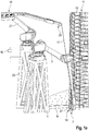
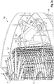
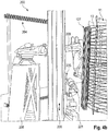
- FIG. 1a a system 1 according to a first embodiment of the invention is shown.
- the plant 1 has a first handling robot 3, which is designed to form helically arranged stiffening elements 27 by means of corresponding bending means.
- the first handling robot 3 has a working head with a bending device 19.
- the first handling robot 3 is according to FIGS. 1a . b arranged on a support structure 5. This can be a pedestal like in FIGS. 1a . b , or another support structure, as shown for example in one of the further embodiments.
- the system 1 has a receiving area 7.
- the receiving area 7 is adapted to receive a gripping device 11.
- the gripping device 11 has coupling means, for example in the form of hook-shaped arithmetic arms, on each of which substantially horizontally oriented ring elements 13 are arranged.
- the receiving area 7 is arranged on a preferably rotatable platform 9.
- the platform 9 is preferably connected in terms of data to an electronic control unit, so that the rotation can be coordinated according to the work progress of the handling robots 3 and 21 by means of the electronic control unit.
- the first handling robot 3 is connected, among other things, to a feed unit 15 by means of an electronic control device and cooperates therewith so that the feed unit 15 can supply the handling robot 3 with an endless material 17 for producing the helical stiffening elements 27.
- the system 1 also has a second handling robot 21, which has a working head 25 with a connecting means, for example designed as a welding wheel.
- the second handling robot 21 is preferably is also connected to the electronic control unit and cooperates with the first handling robot 3 and the platform 9 to connect the stiffening elements 27 produced with the substantially horizontally oriented ring elements 13, which are held by the gripping device 11.
- the second handling robot 21 may, for example, be arranged on a support structure 23 adjacent to the receiving area 7, or on an alternative support structure together with the first handling robot, as shown for example in the following embodiments.
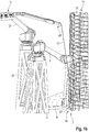
- the first handling robot 3 is multi-axially movable to allow the working head 19 to create bends in the continuous material 17 so as to form the substantially vertically oriented stiffening elements 27.
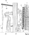
- the working head 19 is for this purpose also reconfigurable and implementable, as in FIG. 1b is shown, and in particular in the FIGS. 2a to 2g is pictured.
- the system also has an electronic control device 10 for the coordinated control of the handling robots 3, 21 and the platform 9.
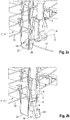
- FIGS. 2a to 2g a section of the system 1 according to the first embodiment is shown, in which the working head 19 of the first handling robot 3 is shown in operation.
- a first substantially vertically aligned stiffening element 27 has already been created adjacent to the ring elements 13 in the receiving area 7.
- the working head 19 has a base body 29, on which a plurality of deflection rollers 31a, b, c (FIG. FIGS. 2c to 2g ) are arranged.
- FIG. 2a a first bend has been created for a stiffening element 27.
- the endless material 17 is based on the state according to FIG. 2a in FIG. 2b further deformed by adding another bend.
- the first handling robot 3 has performed a corresponding pivoting movement about a working axis b.
- the first handling robot 3 sets according to the state FIG. 2b from short and swings the hull of the handling robot 3 to the outside, so that the first Handling robot 3 when further guiding the endless material 17 upwards to the next produced bend not collided.
- the trained with bending means in the form of a bending device working head 19 of the first handling robot 3 has adjustable guide rollers 31a, b, c, which are arranged on the base body 29.
- An exemplary conversion of the role positions, associated with a transfer movement of the working head 19 are in the FIGS. 2c to 2g illustrated.
- Figure 2c is the working head 19 on the first handling robot 3 initially still in engagement with the endless material 17.
- the working head 19 is pivoted about an axis c on the first handling robot 3 in the direction of the arrow 33, so that the rollers 31a, b, c are disengaged from the endless material 17.
- FIG. 2e results, the positions of the rollers 31a and 31c are changed in a first direction, while the deflection roller 31b arranged between the deflection rollers 31a, c is displaced in the opposite direction.
- the repositioning of the deflection rollers 31a, b, c can be either stepless or rasterized, for example, by converting into dedicated openings.
- FIG. 2f the working head 19 is pivoted again in the direction of the arrow 35 about the axis c, so that the deflection rollers 31a, b, c are again in engagement with the endless material 17.
- Figure 2g displayed.
- the rotational position of the main body 29 is constant relative to the first handling robot 3. It is optional but also possible to pivot the main body 29 of the working head 19 about an axis a, such as in the comparison of FIG. 2b apparently with 2c.
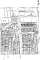
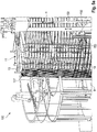
- FIGS. 3a . b schematically show a section of a plant 100 according to a second embodiment of the invention.
- the essential inventive features are the same as in the first embodiment.
- the type of arrangement of a first handling robot 103 of the system 100 and a second handling robot 121 of the system 100 are in Principle can be exchanged or combined with the type of arrangement in system 1.
- the first handling robot 103 of the installation 100 has on its working head 119 a gripping device with which the handling robot 103 can grasp stiffening elements 127 from the inside and hold them non-slip.
- the stiffening elements 127 according to the second embodiment are separate, preferably closed, bracket.
- the first handling robot 103 is adapted to remove the bow-shaped stiffening elements 127 with the working head 119 designed as a gripping device from a storage, to bring into abutment with the ring elements 13 on the gripping device 11 of the system 100, and to put there until the second Handling robot 121 with its trained as a welding device working head 125, for example, as a welding wheel, the stiffening elements 127 has connected to the ring elements 13.
- the first handling robot 103 and the second handling robot 121 are according to FIG FIGS. 3a . b on a gripping device 11 and the (not shown) rotatable platform 9 ( FIG. 1a ) surrounding annular platform 105.
- support structures such as in FIG. 1a . b be selected, just as in the first embodiment of Appendix 1 in the FIGS. 1a . b a support structure such as the platform 105 shown here could be selected.
- FIGS. 4a to 4c The exact execution of the storage is not shown in this embodiment for reasons of clarity. It may, for example, a storage such as the storage 204 from the embodiment of the illustrated below FIGS. 4a to 4c be.
- the second handling robot 121 In the state according to FIG. 3a the second handling robot 121 is positioned such that a stiffening element 127 is connected to one of the ring elements 13 in the upper region of the reinforcement cage to be created.
- the second handling robot 121 is positioned so that the working head 125 can connect the stiffening element 127 in a lower region of the reinforcing cage to be produced in the gripping device 11 with a ring element or, alternatively, performs a welding on the stiffening element 127 itself.
- the first handling robot 103 holds the stiffening element 127 non-slip in position during these operations. This is done by means of pivotable coupling members which are arranged at opposite ends of the working head 119.
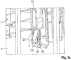
- Figure 3c shows coupling link 141, although obscured by the working head 125 of the second handling robot 121. The coupling member with its components is also explained in more detail in an embodiment to be discussed below also.
- the coupling member 141 which is in Figure 3c is seen, at a first end on a guide roller 145, which is adapted to be inserted into the bend, thus corner, a stiffening element 127 and to detect the stiffening element there.
- a support portion 147 is arranged, which is adapted to exert a pivoting of the coupling member 141 together with the guide roller 145 an expanding force on the stiffening member 127 which is large enough to the stiffening member 127 non-slip to be able to hold.
- the coupling member 141 is preferably movable by means of an actuator 143.
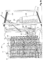
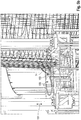
- FIGS. 4a to 4c a plant 200 for the production of reinforcement cages according to a third embodiment is shown.
- the third embodiment is structurally very similar to the second embodiment, it is therefore only pointed to constructive differences.
- the system 200 has a height-adjustable portal 206, on which a second handling robot 221 is arranged to be vertically movable.
- a first handling robot 203 is mounted separately on the second handling robot 221 on a support structure 205.
- the system 200 has a storage 204 of stiffening elements 127.
- the first handling robot 203 is configured to remove these stiffening elements 127 from the storage 204 and to place them against the ring elements 13, which are held on the gripping device 11 and arranged in the receiving area 7 on a rotatable platform 9.
- This removal process is exemplified.
- FIG. 4b that the same plant 200 out FIG. 4a shows in a different angle, the first handling robot 203 has brought a previously removed stiffening element 127 into abutment with the ring elements 13 on the gripping device 11.
- the second handling robot 221 is adapted to move along the portal 206 in height to the appropriate location, and then bring a working head 225 in position, which connects the stiffening element 127 with a portion of a ring element 13 at different heights along the Produces reinforcement cage.
- the substantially horizontally oriented ring members 13 were the ring members for a so-called inner helix of the reinforcing cage to be manufactured. It is also within the scope of the invention that these ring elements represent a so-called outer helix, in which case the stiffening elements could then be arranged on the inside with reference to these ring elements. Corresponding changes to the handling robot positions are not shown in all combinations for reasons of clarity.
- an inner helix for the substantially horizontally oriented ring elements 13 it is in the context of another embodiment, which is to be understood as an addition to all embodiments previously shown, but by way of example only with reference to the embodiment of the FIGS. 3a to 3c is imaged, provided that the substantially horizontally oriented ring elements 13 represent a first set of ring elements.
- an automatic winding unit 150 is provided in the system 100, which is adapted to a second set of substantially horizontally oriented on a relative to the first set of ring elements opposite side of the stiffening elements 127 (or the helically shaped stiffening elements 27 in the first embodiment) To provide ring elements 14.
- the winding unit 150 has a guide device 153, which is adapted to a continuous material, which is the same Endless material for the helically formed stiffening elements 27 of FIGS. 1a to 2g may be, annularly or helically around the stiffening elements 127 to lay around.
- the winding unit 150 is moved in a height-adjustable manner on a gantry 151, while the platform 9 is rotated about a vertically aligned axis e together with the gripping device 11, the ring elements 13 and the stiffening elements 127.
- the continuous material is preferably provided by a supply means in the form of a storage 155, which can hold a drum-like winding of the continuous material.
- the guide device 153 may have a plurality of guide rollers, which allow a targeted dispensing of the continuous material for forming the rings 14.
- the winding unit 150 is preferably connected in terms of data to a central electronic control unit, for example the one mentioned above, which coordinates the work of the various system components such as handling robot, winding unit and rotatable platform. This control unit is in FIG. 1a indicated.
- the winding unit which in the FIGS. 5a . b is shown, for example, be the feeder 15, which in the embodiment of the FIGS. 1a to 2g is used to provide the continuous material 17.
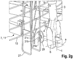
- the plant 1 according to the embodiment of the FIGS. 1a to 2g preferably has another handling robot 61.
- the handling robot 61 is in particular designed identically to the first handling robot 103 from the exemplary embodiment of FIG FIGS. 3a to c.
- this handling robot 61 can also be used in the system 1 with advantage, by engaging it to stabilize the already formed helical stiffening elements 27 in this and holds as long as non-slip until the second handling robot 21 has performed the required connection work between the stiffening elements 27 and the ring elements 13.
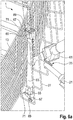
- FIGS. 6b to c are regarding the in FIG. 6a visible, designed as a gripping device working head 63 of the handling robot 61 further details shown in the working head 119 of the embodiment of FIGS. 3a to c for the sake of simplicity of illustration just as in the embodiment of FIGS. 4a to c were omitted.
- the coupling device here reference numeral 67 instead of reference numeral 141, is arranged movably on the working head 63 by means of an actuator 65.
- the support section now has the reference numeral 71, and the guide roller the reference numeral 69.
- the operation of the coupling member is exemplified in the FIGS. 6b, c shown.
- the gripping device 63 in the in FIG. 6a shown state spent.
- FIG. 6b shown coupling member 67 in the "inner region" of a corner of a coil of the stiffening elements 27. From this position, a piston rod 75 is extended in the direction of arrow 73 by means of the actuator 65. This is after FIG. 6c As a result, the guide roller 69 of the coupling member abuts against an end portion 27a of the stiffening member 27 and, with continued movement of the piston rod 75, rolls in the direction of one of the bending corners. In FIG. 6c the guide roller 69 has arrived in the bend corner 27b.
- the piston rod 75 has moved so far by means of the actuator 65 that the support section 71 arranged at the opposite end of the coupling element 67, relative to the guide roller 69, is in contact with a substantially vertical section 27c of the stiffening element 27.
- the actuator 65 is able, by further pushing out of the piston rod 75, to exert an expanding force on the stiffening element 27, by means of which it is fixed and stabilized.
- connecting the stiffening elements in the immediate vicinity of the held stiffening element 27, including the stiffening element 27 itself, by the second handling robot 21 is possible.
Landscapes
- Engineering & Computer Science (AREA)
- Mechanical Engineering (AREA)
- Architecture (AREA)
- Life Sciences & Earth Sciences (AREA)
- Chemical & Material Sciences (AREA)
- Structural Engineering (AREA)
- Civil Engineering (AREA)
- Sustainable Development (AREA)
- Sustainable Energy (AREA)
- Combustion & Propulsion (AREA)
- General Engineering & Computer Science (AREA)
- Robotics (AREA)
- Materials Engineering (AREA)
- Wood Science & Technology (AREA)
- Wire Processing (AREA)
- Wind Motors (AREA)
- Manipulator (AREA)
- Conveying And Assembling Of Building Elements In Situ (AREA)
Applications Claiming Priority (2)
| Application Number | Priority Date | Filing Date | Title |
|---|---|---|---|
| DE102013225049.5A DE102013225049A1 (de) | 2013-12-05 | 2013-12-05 | Anlage zur Herstellung von Bewehrungskörben für Turmsegmente von Windenergieanlagen |
| PCT/EP2014/072205 WO2015082115A1 (de) | 2013-12-05 | 2014-10-16 | Anlage zur herstellung von bewehrungskörben für turmsegmente von windenergieanlagen |
Publications (2)
| Publication Number | Publication Date |
|---|---|
| EP3077136A1 EP3077136A1 (de) | 2016-10-12 |
| EP3077136B1 true EP3077136B1 (de) | 2017-09-06 |
Family
ID=51752114
Family Applications (1)
| Application Number | Title | Priority Date | Filing Date |
|---|---|---|---|
| EP14786489.6A Active EP3077136B1 (de) | 2013-12-05 | 2014-10-16 | Anlage zur herstellung von bewehrungskörben für turmsegmente von windenergieanlagen |
Country Status (12)
| Country | Link |
|---|---|
| US (1) | US10094114B2 (da) |
| EP (1) | EP3077136B1 (da) |
| CN (1) | CN105792959B (da) |
| AR (1) | AR098608A1 (da) |
| BR (1) | BR112016012526A2 (da) |
| CA (1) | CA2930009C (da) |
| DE (1) | DE102013225049A1 (da) |
| DK (1) | DK3077136T3 (da) |
| ES (1) | ES2649731T3 (da) |
| PT (1) | PT3077136T (da) |
| TW (1) | TWI569904B (da) |
| WO (1) | WO2015082115A1 (da) |
Families Citing this family (12)
| Publication number | Priority date | Publication date | Assignee | Title |
|---|---|---|---|---|
| AT517912B1 (de) * | 2015-10-21 | 2019-03-15 | Hubert Ing Rapperstorfer | Fertigungsanlage zum Fertigen von Bewehrungselementen |
| WO2017153559A1 (en) * | 2016-03-10 | 2017-09-14 | ETH Zürich | Digital method and automated robotic setup for producing variable-density and arbitrary shaped metallic meshes |
| CN109129881A (zh) * | 2017-06-27 | 2019-01-04 | 黄冈昌耀电力器材有限公司 | 一种组装式拔梢环形混凝土电杆连接构件成型定位工艺 |
| BR112021006172A2 (pt) * | 2018-10-18 | 2021-06-29 | Toggle Industries | gabaritos modulares, sistema de montagem de gaiola de vergalhão e método para montar uma gaiola de vergalhão |
| ES3023213T3 (en) * | 2019-03-19 | 2025-05-30 | Gmt Robotics Aps | Assembly machine and a method for manufacturing reinforcement structures |
| EP3903959B1 (en) * | 2020-04-28 | 2025-11-05 | Mesh AG | Primary building structure fabrication system |
| EP3905205A1 (en) * | 2020-04-28 | 2021-11-03 | ETH Zurich | Data processing for complex three-dimensional mesh structure |
| EP3903960A1 (en) * | 2020-04-28 | 2021-11-03 | ETH Zurich | Building structure fabrication system |
| CN113601050A (zh) * | 2021-07-09 | 2021-11-05 | 河南永益同丰智能科技有限公司 | 一种六轴钢筋笼自动焊机器人手臂 |
| EP4353380A1 (de) | 2022-10-14 | 2024-04-17 | Progress Maschinen & Automation AG | Verfahren und vorrichtung zur automatisierten herstellung eines bewehrungskorbes |
| US12319001B2 (en) | 2022-11-16 | 2025-06-03 | Ge Vernova Infrastructure Technology Llc | Methods of additively manufacturing tower structures with coiled polymer reinforcement members |
| CN115958366B (zh) * | 2023-02-21 | 2023-05-23 | 成都中挖属汇科技有限公司 | 一种标准节组装焊接工装 |
Family Cites Families (20)
| Publication number | Priority date | Publication date | Assignee | Title |
|---|---|---|---|---|
| US3125132A (en) * | 1964-03-17 | Method and means for making cages for | ||
| US2050832A (en) * | 1934-09-12 | 1936-08-11 | Lamar Pipe And Tile Company | Machine for making reticulated wire structures |
| US3280855A (en) * | 1962-06-25 | 1966-10-25 | Jr Leroy Magers | Reinforcing cage apparatus |
| US3310074A (en) * | 1963-12-09 | 1967-03-21 | American Pipe & Constr Co | Means for controlling manufacture of wire cages |
| DE1552131A1 (de) * | 1965-10-07 | 1969-08-21 | American Pipe & Constr Co | Maschine zur Herstellung von Drahtarmierungskaefigen |
| DE2432855A1 (de) | 1974-07-09 | 1976-01-29 | Zueblin Ag | Maschine zur herstellung von bewehrungskoerben fuer stahlbeton-pfaehle, -masten, -rohre o.dgl. |
| US4478260A (en) * | 1981-08-17 | 1984-10-23 | Braun Nursery Limited | Wire basket, apparatus and method |
| DE3634736C2 (de) | 1986-10-11 | 1995-11-16 | Mbk Maschinenbau Gmbh | Maschine zur Herstellung rohrförmiger Bewehrungskörper für Betonrohre |
| DE3809420C1 (en) * | 1988-03-21 | 1989-08-10 | Ed. Zueblin Ag, 7000 Stuttgart, De | Machine for producing reinforcing cages for reinforced-concrete pipes in vertical type of fabrication |
| DE4133589A1 (de) * | 1990-10-12 | 1992-04-16 | Wolfgang Reymann | Vorrichtung zur erstellung von bewehrungen |
| CH684934A5 (de) * | 1991-08-23 | 1995-02-15 | Mtf Datentechnik Ag | Verfahren und Vorrichtung zur Herstellung von Bewehrungen. |
| DE19814091A1 (de) | 1998-03-30 | 1999-10-07 | Mbk Maschinenbau Gmbh | Vorrichtung zur Herstellung von Bewehrungskörben für Rechteckrohre aus Beton |
| DE19830414B4 (de) * | 1998-04-21 | 2004-02-05 | Rainer Knecht | Verfahren und Vorrichtung zur Herstellung von Bewehrungen |
| NL1030978C2 (nl) | 2006-01-23 | 2007-07-24 | Gerardus Alexander Verschuren | Inrichting en werkwijze voor het vervaardigen van wapeningselementen. |
| CN101700555B (zh) | 2009-11-20 | 2011-06-15 | 天津市建科机械制造有限公司 | 数控钢筋笼成型机的自动焊接机械装置 |
| CN201552575U (zh) | 2009-11-20 | 2010-08-18 | 天津市建科机械制造有限公司 | 钢筋笼成型机的自动焊接机械手 |
| CN201880834U (zh) | 2010-11-17 | 2011-06-29 | 天津市建科机械制造有限公司 | 数控钢筋笼成型机的旋转驱动机构 |
| DE102012216831A1 (de) | 2012-09-19 | 2014-03-20 | Wobben Properties Gmbh | Vorrichtung und Verfahren zum automatischen Verdrillen von Metalldrähten, insbesondere zum Verbinden benachbarter, vorzugsweise sich überkreuzender Strukturelemente |
| DE102012221453A1 (de) | 2012-11-23 | 2014-05-28 | Wobben Properties Gmbh | Greifeinrichtung zum Handhaben von Bewehrungskörben für Turmsegmente einer Windenergieanlage |
| WO2016063221A1 (en) * | 2014-10-20 | 2016-04-28 | Schnell S.P.A. | Device for forming binding elements |
-
2013
- 2013-12-05 DE DE102013225049.5A patent/DE102013225049A1/de not_active Ceased
-
2014
- 2014-10-16 EP EP14786489.6A patent/EP3077136B1/de active Active
- 2014-10-16 DK DK14786489.6T patent/DK3077136T3/da active
- 2014-10-16 PT PT147864896T patent/PT3077136T/pt unknown
- 2014-10-16 BR BR112016012526A patent/BR112016012526A2/pt not_active Application Discontinuation
- 2014-10-16 US US15/101,848 patent/US10094114B2/en not_active Expired - Fee Related
- 2014-10-16 ES ES14786489.6T patent/ES2649731T3/es active Active
- 2014-10-16 CA CA2930009A patent/CA2930009C/en not_active Expired - Fee Related
- 2014-10-16 CN CN201480066702.8A patent/CN105792959B/zh not_active Expired - Fee Related
- 2014-10-16 WO PCT/EP2014/072205 patent/WO2015082115A1/de not_active Ceased
- 2014-11-10 TW TW103138943A patent/TWI569904B/zh not_active IP Right Cessation
- 2014-12-04 AR ARP140104505A patent/AR098608A1/es unknown
Non-Patent Citations (1)
| Title |
|---|
| None * |
Also Published As
| Publication number | Publication date |
|---|---|
| ES2649731T3 (es) | 2018-01-15 |
| EP3077136A1 (de) | 2016-10-12 |
| DE102013225049A1 (de) | 2015-06-11 |
| CN105792959B (zh) | 2018-09-04 |
| US10094114B2 (en) | 2018-10-09 |
| WO2015082115A1 (de) | 2015-06-11 |
| CN105792959A (zh) | 2016-07-20 |
| US20160305125A1 (en) | 2016-10-20 |
| CA2930009C (en) | 2019-03-05 |
| CA2930009A1 (en) | 2015-06-11 |
| DK3077136T3 (da) | 2017-10-30 |
| AR098608A1 (es) | 2016-06-01 |
| TW201532703A (zh) | 2015-09-01 |
| TWI569904B (zh) | 2017-02-11 |
| BR112016012526A2 (pt) | 2017-08-08 |
| PT3077136T (pt) | 2017-12-04 |
Similar Documents
| Publication | Publication Date | Title |
|---|---|---|
| EP3077136B1 (de) | Anlage zur herstellung von bewehrungskörben für turmsegmente von windenergieanlagen | |
| EP2922779B1 (de) | Greifeinrichtung zum handhaben von bewehrungskörben für turmsegmente einer windenergieanlage | |
| EP2825493B1 (de) | Spulenwechselvorrichtung | |
| EP2349605B1 (de) | Vorrichtung und verfahren zur herstellung von federn | |
| EP3579987B1 (de) | Biegewerkzeug-speichervorrichtung und verfahren zum beschicken einer biegepresse | |
| EP2726230B1 (de) | Verfahren und einrichtung zur kontinuierlichen herstellung eines gitterträgers | |
| EP3365124A1 (de) | Fertigungsanlage zum fertigen von bewehrungselementen | |
| EP2870297B1 (de) | Fundament für windenergieanlagen | |
| EP3319742B1 (de) | Biegewerkzeug-speichervorrichtung | |
| WO2014044443A1 (de) | Vorrichtung und verfahren zum automatischen verdrillen von metalldrähten, insbesondere zum verbinden benachbarter, vorzugweise sich überkreuzender strukturelemente | |
| EP2789561A1 (de) | Aufzug | |
| DE102014113319A1 (de) | Drahtformvorrichtung | |
| DE69402876T2 (de) | Vorrichtung zur ladung von brennstabbündeln | |
| EP4135916B1 (de) | Mattenschweissanlage zur herstellung von betonstahlmatten und verfahren unter verwendung derselben | |
| DE4139824C1 (da) | ||
| AT517353B1 (de) | Biegewerkzeugspeicher | |
| DE2308533A1 (de) | Vorrichtung zum einfahren von langen, duennen koerpern in enge hohlraeume, insbesondere fuer steuer-abschaltstaebe oder dergl. von kernreaktoren | |
| DE102007048291B3 (de) | Vorrichtung zum Ausrichten von Brennelementen in einem Druckwasserreaktor | |
| DE202014104329U1 (de) | Biegemaschine mit mindestens einer demontierbaren Biegeachsabstützung | |
| EP3695914A1 (de) | Abhaspelvorrichtung und -verfahren | |
| DE2950561C2 (de) | Verteilersystem an einer Vorrichtung zum Stapeln von langgestrecktem, rollfähigem, rohrförmigem Gut | |
| DE1009146B (de) | Einrichtung zum Ziehen von Halbzeug, insbesondere zum Ziehen kleiner und duenner Rohre | |
| DE1118125B (de) | Haspel, insbesondere Edenbornhaspel |
Legal Events
| Date | Code | Title | Description |
|---|---|---|---|
| PUAI | Public reference made under article 153(3) epc to a published international application that has entered the european phase |
Free format text: ORIGINAL CODE: 0009012 |
|
| 17P | Request for examination filed |
Effective date: 20160705 |
|
| AK | Designated contracting states |
Kind code of ref document: A1 Designated state(s): AL AT BE BG CH CY CZ DE DK EE ES FI FR GB GR HR HU IE IS IT LI LT LU LV MC MK MT NL NO PL PT RO RS SE SI SK SM TR |
|
| AX | Request for extension of the european patent |
Extension state: BA ME |
|
| DAX | Request for extension of the european patent (deleted) | ||
| GRAP | Despatch of communication of intention to grant a patent |
Free format text: ORIGINAL CODE: EPIDOSNIGR1 |
|
| INTG | Intention to grant announced |
Effective date: 20170412 |
|
| GRAS | Grant fee paid |
Free format text: ORIGINAL CODE: EPIDOSNIGR3 |
|
| GRAA | (expected) grant |
Free format text: ORIGINAL CODE: 0009210 |
|
| AK | Designated contracting states |
Kind code of ref document: B1 Designated state(s): AL AT BE BG CH CY CZ DE DK EE ES FI FR GB GR HR HU IE IS IT LI LT LU LV MC MK MT NL NO PL PT RO RS SE SI SK SM TR |
|
| REG | Reference to a national code |
Ref country code: GB Ref legal event code: FG4D Free format text: NOT ENGLISH |
|
| REG | Reference to a national code |
Ref country code: CH Ref legal event code: EP Ref country code: AT Ref legal event code: REF Ref document number: 925313 Country of ref document: AT Kind code of ref document: T Effective date: 20170915 |
|
| REG | Reference to a national code |
Ref country code: IE Ref legal event code: FG4D Free format text: LANGUAGE OF EP DOCUMENT: GERMAN |
|
| REG | Reference to a national code |
Ref country code: DE Ref legal event code: R096 Ref document number: 502014005378 Country of ref document: DE |
|
| REG | Reference to a national code |
Ref country code: FR Ref legal event code: PLFP Year of fee payment: 4 |
|
| REG | Reference to a national code |
Ref country code: DK Ref legal event code: T3 Effective date: 20171023 |
|
| REG | Reference to a national code |
Ref country code: PT Ref legal event code: SC4A Ref document number: 3077136 Country of ref document: PT Date of ref document: 20171204 Kind code of ref document: T Free format text: AVAILABILITY OF NATIONAL TRANSLATION Effective date: 20171127 |
|
| REG | Reference to a national code |
Ref country code: SE Ref legal event code: TRGR |
|
| REG | Reference to a national code |
Ref country code: NL Ref legal event code: FP |
|
| REG | Reference to a national code |
Ref country code: ES Ref legal event code: FG2A Ref document number: 2649731 Country of ref document: ES Kind code of ref document: T3 Effective date: 20180115 |
|
| REG | Reference to a national code |
Ref country code: LT Ref legal event code: MG4D |
|
| PG25 | Lapsed in a contracting state [announced via postgrant information from national office to epo] |
Ref country code: HR Free format text: LAPSE BECAUSE OF FAILURE TO SUBMIT A TRANSLATION OF THE DESCRIPTION OR TO PAY THE FEE WITHIN THE PRESCRIBED TIME-LIMIT Effective date: 20170906 Ref country code: FI Free format text: LAPSE BECAUSE OF FAILURE TO SUBMIT A TRANSLATION OF THE DESCRIPTION OR TO PAY THE FEE WITHIN THE PRESCRIBED TIME-LIMIT Effective date: 20170906 Ref country code: NO Free format text: LAPSE BECAUSE OF FAILURE TO SUBMIT A TRANSLATION OF THE DESCRIPTION OR TO PAY THE FEE WITHIN THE PRESCRIBED TIME-LIMIT Effective date: 20171206 Ref country code: LT Free format text: LAPSE BECAUSE OF FAILURE TO SUBMIT A TRANSLATION OF THE DESCRIPTION OR TO PAY THE FEE WITHIN THE PRESCRIBED TIME-LIMIT Effective date: 20170906 |
|
| PG25 | Lapsed in a contracting state [announced via postgrant information from national office to epo] |
Ref country code: LV Free format text: LAPSE BECAUSE OF FAILURE TO SUBMIT A TRANSLATION OF THE DESCRIPTION OR TO PAY THE FEE WITHIN THE PRESCRIBED TIME-LIMIT Effective date: 20170906 Ref country code: RS Free format text: LAPSE BECAUSE OF FAILURE TO SUBMIT A TRANSLATION OF THE DESCRIPTION OR TO PAY THE FEE WITHIN THE PRESCRIBED TIME-LIMIT Effective date: 20170906 Ref country code: BG Free format text: LAPSE BECAUSE OF FAILURE TO SUBMIT A TRANSLATION OF THE DESCRIPTION OR TO PAY THE FEE WITHIN THE PRESCRIBED TIME-LIMIT Effective date: 20171206 |
|
| PG25 | Lapsed in a contracting state [announced via postgrant information from national office to epo] |
Ref country code: CZ Free format text: LAPSE BECAUSE OF FAILURE TO SUBMIT A TRANSLATION OF THE DESCRIPTION OR TO PAY THE FEE WITHIN THE PRESCRIBED TIME-LIMIT Effective date: 20170906 Ref country code: PL Free format text: LAPSE BECAUSE OF FAILURE TO SUBMIT A TRANSLATION OF THE DESCRIPTION OR TO PAY THE FEE WITHIN THE PRESCRIBED TIME-LIMIT Effective date: 20170906 |
|
| REG | Reference to a national code |
Ref country code: GR Ref legal event code: EP Ref document number: 20170403068 Country of ref document: GR Effective date: 20180420 |
|
| PG25 | Lapsed in a contracting state [announced via postgrant information from national office to epo] |
Ref country code: SM Free format text: LAPSE BECAUSE OF FAILURE TO SUBMIT A TRANSLATION OF THE DESCRIPTION OR TO PAY THE FEE WITHIN THE PRESCRIBED TIME-LIMIT Effective date: 20170906 Ref country code: SK Free format text: LAPSE BECAUSE OF FAILURE TO SUBMIT A TRANSLATION OF THE DESCRIPTION OR TO PAY THE FEE WITHIN THE PRESCRIBED TIME-LIMIT Effective date: 20170906 Ref country code: IT Free format text: LAPSE BECAUSE OF FAILURE TO SUBMIT A TRANSLATION OF THE DESCRIPTION OR TO PAY THE FEE WITHIN THE PRESCRIBED TIME-LIMIT Effective date: 20170906 Ref country code: EE Free format text: LAPSE BECAUSE OF FAILURE TO SUBMIT A TRANSLATION OF THE DESCRIPTION OR TO PAY THE FEE WITHIN THE PRESCRIBED TIME-LIMIT Effective date: 20170906 Ref country code: IS Free format text: LAPSE BECAUSE OF FAILURE TO SUBMIT A TRANSLATION OF THE DESCRIPTION OR TO PAY THE FEE WITHIN THE PRESCRIBED TIME-LIMIT Effective date: 20180106 |
|
| REG | Reference to a national code |
Ref country code: CH Ref legal event code: PL |
|
| REG | Reference to a national code |
Ref country code: DE Ref legal event code: R097 Ref document number: 502014005378 Country of ref document: DE |
|
| PG25 | Lapsed in a contracting state [announced via postgrant information from national office to epo] |
Ref country code: MC Free format text: LAPSE BECAUSE OF FAILURE TO SUBMIT A TRANSLATION OF THE DESCRIPTION OR TO PAY THE FEE WITHIN THE PRESCRIBED TIME-LIMIT Effective date: 20170906 |
|
| PLBE | No opposition filed within time limit |
Free format text: ORIGINAL CODE: 0009261 |
|
| STAA | Information on the status of an ep patent application or granted ep patent |
Free format text: STATUS: NO OPPOSITION FILED WITHIN TIME LIMIT |
|
| REG | Reference to a national code |
Ref country code: IE Ref legal event code: MM4A |
|
| PG25 | Lapsed in a contracting state [announced via postgrant information from national office to epo] |
Ref country code: LI Free format text: LAPSE BECAUSE OF NON-PAYMENT OF DUE FEES Effective date: 20171031 Ref country code: CH Free format text: LAPSE BECAUSE OF NON-PAYMENT OF DUE FEES Effective date: 20171031 Ref country code: LU Free format text: LAPSE BECAUSE OF NON-PAYMENT OF DUE FEES Effective date: 20171016 |
|
| 26N | No opposition filed |
Effective date: 20180607 |
|
| REG | Reference to a national code |
Ref country code: BE Ref legal event code: MM Effective date: 20171031 |
|
| PG25 | Lapsed in a contracting state [announced via postgrant information from national office to epo] |
Ref country code: SI Free format text: LAPSE BECAUSE OF FAILURE TO SUBMIT A TRANSLATION OF THE DESCRIPTION OR TO PAY THE FEE WITHIN THE PRESCRIBED TIME-LIMIT Effective date: 20170906 Ref country code: BE Free format text: LAPSE BECAUSE OF NON-PAYMENT OF DUE FEES Effective date: 20171031 |
|
| PG25 | Lapsed in a contracting state [announced via postgrant information from national office to epo] |
Ref country code: MT Free format text: LAPSE BECAUSE OF FAILURE TO SUBMIT A TRANSLATION OF THE DESCRIPTION OR TO PAY THE FEE WITHIN THE PRESCRIBED TIME-LIMIT Effective date: 20170906 |
|
| REG | Reference to a national code |
Ref country code: FR Ref legal event code: PLFP Year of fee payment: 5 |
|
| PG25 | Lapsed in a contracting state [announced via postgrant information from national office to epo] |
Ref country code: IE Free format text: LAPSE BECAUSE OF NON-PAYMENT OF DUE FEES Effective date: 20171016 |
|
| PG25 | Lapsed in a contracting state [announced via postgrant information from national office to epo] |
Ref country code: HU Free format text: LAPSE BECAUSE OF FAILURE TO SUBMIT A TRANSLATION OF THE DESCRIPTION OR TO PAY THE FEE WITHIN THE PRESCRIBED TIME-LIMIT; INVALID AB INITIO Effective date: 20141016 |
|
| PG25 | Lapsed in a contracting state [announced via postgrant information from national office to epo] |
Ref country code: RO Free format text: LAPSE BECAUSE OF FAILURE TO SUBMIT A TRANSLATION OF THE DESCRIPTION OR TO PAY THE FEE WITHIN THE PRESCRIBED TIME-LIMIT Effective date: 20170906 |
|
| PG25 | Lapsed in a contracting state [announced via postgrant information from national office to epo] |
Ref country code: CY Free format text: LAPSE BECAUSE OF FAILURE TO SUBMIT A TRANSLATION OF THE DESCRIPTION OR TO PAY THE FEE WITHIN THE PRESCRIBED TIME-LIMIT Effective date: 20170906 |
|
| PG25 | Lapsed in a contracting state [announced via postgrant information from national office to epo] |
Ref country code: MK Free format text: LAPSE BECAUSE OF FAILURE TO SUBMIT A TRANSLATION OF THE DESCRIPTION OR TO PAY THE FEE WITHIN THE PRESCRIBED TIME-LIMIT Effective date: 20170906 |
|
| PGFP | Annual fee paid to national office [announced via postgrant information from national office to epo] |
Ref country code: NL Payment date: 20191022 Year of fee payment: 6 Ref country code: PT Payment date: 20191014 Year of fee payment: 6 Ref country code: SE Payment date: 20191023 Year of fee payment: 6 |
|
| PGFP | Annual fee paid to national office [announced via postgrant information from national office to epo] |
Ref country code: DK Payment date: 20191022 Year of fee payment: 6 Ref country code: GR Payment date: 20191018 Year of fee payment: 6 Ref country code: ES Payment date: 20191120 Year of fee payment: 6 Ref country code: FR Payment date: 20191022 Year of fee payment: 6 |
|
| PG25 | Lapsed in a contracting state [announced via postgrant information from national office to epo] |
Ref country code: TR Free format text: LAPSE BECAUSE OF FAILURE TO SUBMIT A TRANSLATION OF THE DESCRIPTION OR TO PAY THE FEE WITHIN THE PRESCRIBED TIME-LIMIT Effective date: 20170906 |
|
| PGFP | Annual fee paid to national office [announced via postgrant information from national office to epo] |
Ref country code: AT Payment date: 20191018 Year of fee payment: 6 |
|
| PGFP | Annual fee paid to national office [announced via postgrant information from national office to epo] |
Ref country code: GB Payment date: 20191023 Year of fee payment: 6 |
|
| PG25 | Lapsed in a contracting state [announced via postgrant information from national office to epo] |
Ref country code: AL Free format text: LAPSE BECAUSE OF FAILURE TO SUBMIT A TRANSLATION OF THE DESCRIPTION OR TO PAY THE FEE WITHIN THE PRESCRIBED TIME-LIMIT Effective date: 20170906 |
|
| REG | Reference to a national code |
Ref country code: DK Ref legal event code: EBP Effective date: 20201031 |
|
| REG | Reference to a national code |
Ref country code: SE Ref legal event code: EUG |
|
| REG | Reference to a national code |
Ref country code: NL Ref legal event code: MM Effective date: 20201101 |
|
| REG | Reference to a national code |
Ref country code: AT Ref legal event code: MM01 Ref document number: 925313 Country of ref document: AT Kind code of ref document: T Effective date: 20201016 |
|
| GBPC | Gb: european patent ceased through non-payment of renewal fee |
Effective date: 20201016 |
|
| PG25 | Lapsed in a contracting state [announced via postgrant information from national office to epo] |
Ref country code: FR Free format text: LAPSE BECAUSE OF NON-PAYMENT OF DUE FEES Effective date: 20201031 Ref country code: GR Free format text: LAPSE BECAUSE OF NON-PAYMENT OF DUE FEES Effective date: 20210510 Ref country code: PT Free format text: LAPSE BECAUSE OF NON-PAYMENT OF DUE FEES Effective date: 20210416 Ref country code: NL Free format text: LAPSE BECAUSE OF NON-PAYMENT OF DUE FEES Effective date: 20201101 |
|
| PG25 | Lapsed in a contracting state [announced via postgrant information from national office to epo] |
Ref country code: SE Free format text: LAPSE BECAUSE OF NON-PAYMENT OF DUE FEES Effective date: 20201017 Ref country code: GB Free format text: LAPSE BECAUSE OF NON-PAYMENT OF DUE FEES Effective date: 20201016 Ref country code: AT Free format text: LAPSE BECAUSE OF NON-PAYMENT OF DUE FEES Effective date: 20201016 |
|
| PG25 | Lapsed in a contracting state [announced via postgrant information from national office to epo] |
Ref country code: DK Free format text: LAPSE BECAUSE OF NON-PAYMENT OF DUE FEES Effective date: 20201031 |
|
| REG | Reference to a national code |
Ref country code: ES Ref legal event code: FD2A Effective date: 20220121 |
|
| PG25 | Lapsed in a contracting state [announced via postgrant information from national office to epo] |
Ref country code: ES Free format text: LAPSE BECAUSE OF NON-PAYMENT OF DUE FEES Effective date: 20201017 |
|
| PGFP | Annual fee paid to national office [announced via postgrant information from national office to epo] |
Ref country code: DE Payment date: 20241107 Year of fee payment: 11 |