EP3077136B1 - Installation for producing reinforcement cages for tower segments of wind turbines - Google Patents
Installation for producing reinforcement cages for tower segments of wind turbines Download PDFInfo
- Publication number
- EP3077136B1 EP3077136B1 EP14786489.6A EP14786489A EP3077136B1 EP 3077136 B1 EP3077136 B1 EP 3077136B1 EP 14786489 A EP14786489 A EP 14786489A EP 3077136 B1 EP3077136 B1 EP 3077136B1
- Authority
- EP
- European Patent Office
- Prior art keywords
- elements
- handling robot
- stiffening
- stiffening elements
- handling
- Prior art date
- Legal status (The legal status is an assumption and is not a legal conclusion. Google has not performed a legal analysis and makes no representation as to the accuracy of the status listed.)
- Active
Links
- 230000002787 reinforcement Effects 0.000 title description 12
- 238000009434 installation Methods 0.000 title description 3
- 230000003014 reinforcing effect Effects 0.000 claims description 25
- 230000008878 coupling Effects 0.000 claims description 22
- 238000010168 coupling process Methods 0.000 claims description 22
- 238000005859 coupling reaction Methods 0.000 claims description 22
- 238000005452 bending Methods 0.000 claims description 21
- 239000000463 material Substances 0.000 claims description 21
- 238000004804 winding Methods 0.000 claims description 9
- 238000003466 welding Methods 0.000 claims description 6
- 229910000831 Steel Inorganic materials 0.000 claims description 4
- 239000010959 steel Substances 0.000 claims description 4
- 239000002184 metal Substances 0.000 claims description 3
- 239000000853 adhesive Substances 0.000 claims description 2
- 230000001070 adhesive effect Effects 0.000 claims description 2
- 238000005476 soldering Methods 0.000 claims description 2
- 238000003892 spreading Methods 0.000 claims description 2
- 230000001419 dependent effect Effects 0.000 claims 3
- 241000237519 Bivalvia Species 0.000 claims 1
- 235000020639 clam Nutrition 0.000 claims 1
- 238000004519 manufacturing process Methods 0.000 description 11
- 239000000109 continuous material Substances 0.000 description 9
- 238000003860 storage Methods 0.000 description 9
- 229910001294 Reinforcing steel Inorganic materials 0.000 description 4
- 238000006243 chemical reaction Methods 0.000 description 2
- 239000004567 concrete Substances 0.000 description 2
- 238000000034 method Methods 0.000 description 2
- 239000004237 Ponceau 6R Substances 0.000 description 1
- 230000001133 acceleration Effects 0.000 description 1
- 238000010276 construction Methods 0.000 description 1
- NJPPVKZQTLUDBO-UHFFFAOYSA-N novaluron Chemical compound C1=C(Cl)C(OC(F)(F)C(OC(F)(F)F)F)=CC=C1NC(=O)NC(=O)C1=C(F)C=CC=C1F NJPPVKZQTLUDBO-UHFFFAOYSA-N 0.000 description 1
- 239000011150 reinforced concrete Substances 0.000 description 1
- 230000000087 stabilizing effect Effects 0.000 description 1
Images


Classifications
-
- B—PERFORMING OPERATIONS; TRANSPORTING
- B21—MECHANICAL METAL-WORKING WITHOUT ESSENTIALLY REMOVING MATERIAL; PUNCHING METAL
- B21F—WORKING OR PROCESSING OF METAL WIRE
- B21F23/00—Feeding wire in wire-working machines or apparatus
-
- E—FIXED CONSTRUCTIONS
- E04—BUILDING
- E04C—STRUCTURAL ELEMENTS; BUILDING MATERIALS
- E04C5/00—Reinforcing elements, e.g. for concrete; Auxiliary elements therefor
- E04C5/01—Reinforcing elements of metal, e.g. with non-structural coatings
- E04C5/06—Reinforcing elements of metal, e.g. with non-structural coatings of high bending resistance, i.e. of essentially three-dimensional extent, e.g. lattice girders
- E04C5/0604—Prismatic or cylindrical reinforcement cages composed of longitudinal bars and open or closed stirrup rods
- E04C5/0609—Closed cages composed of two or more coacting cage parts, e.g. transversally hinged or nested parts
-
- B—PERFORMING OPERATIONS; TRANSPORTING
- B21—MECHANICAL METAL-WORKING WITHOUT ESSENTIALLY REMOVING MATERIAL; PUNCHING METAL
- B21F—WORKING OR PROCESSING OF METAL WIRE
- B21F27/00—Making wire network, i.e. wire nets
- B21F27/08—Making wire network, i.e. wire nets with additional connecting elements or material at crossings
- B21F27/10—Making wire network, i.e. wire nets with additional connecting elements or material at crossings with soldered or welded crossings
-
- B—PERFORMING OPERATIONS; TRANSPORTING
- B21—MECHANICAL METAL-WORKING WITHOUT ESSENTIALLY REMOVING MATERIAL; PUNCHING METAL
- B21F—WORKING OR PROCESSING OF METAL WIRE
- B21F27/00—Making wire network, i.e. wire nets
- B21F27/12—Making special types or portions of network by methods or means specially adapted therefor
- B21F27/121—Making special types or portions of network by methods or means specially adapted therefor of tubular form, e.g. as reinforcements for pipes or pillars
- B21F27/122—Making special types or portions of network by methods or means specially adapted therefor of tubular form, e.g. as reinforcements for pipes or pillars by attaching a continuous stirrup to longitudinal wires
- B21F27/124—Making special types or portions of network by methods or means specially adapted therefor of tubular form, e.g. as reinforcements for pipes or pillars by attaching a continuous stirrup to longitudinal wires applied by rotation
-
- B—PERFORMING OPERATIONS; TRANSPORTING
- B21—MECHANICAL METAL-WORKING WITHOUT ESSENTIALLY REMOVING MATERIAL; PUNCHING METAL
- B21F—WORKING OR PROCESSING OF METAL WIRE
- B21F27/00—Making wire network, i.e. wire nets
- B21F27/12—Making special types or portions of network by methods or means specially adapted therefor
- B21F27/121—Making special types or portions of network by methods or means specially adapted therefor of tubular form, e.g. as reinforcements for pipes or pillars
- B21F27/125—Making special types or portions of network by methods or means specially adapted therefor of tubular form, e.g. as reinforcements for pipes or pillars by attaching individual stirrups to longitudinal wires
-
- B—PERFORMING OPERATIONS; TRANSPORTING
- B25—HAND TOOLS; PORTABLE POWER-DRIVEN TOOLS; MANIPULATORS
- B25J—MANIPULATORS; CHAMBERS PROVIDED WITH MANIPULATION DEVICES
- B25J9/00—Programme-controlled manipulators
- B25J9/16—Programme controls
- B25J9/1679—Programme controls characterised by the tasks executed
- B25J9/1682—Dual arm manipulator; Coordination of several manipulators
-
- B—PERFORMING OPERATIONS; TRANSPORTING
- B25—HAND TOOLS; PORTABLE POWER-DRIVEN TOOLS; MANIPULATORS
- B25J—MANIPULATORS; CHAMBERS PROVIDED WITH MANIPULATION DEVICES
- B25J9/00—Programme-controlled manipulators
- B25J9/16—Programme controls
- B25J9/1679—Programme controls characterised by the tasks executed
- B25J9/1687—Assembly, peg and hole, palletising, straight line, weaving pattern movement
-
- E—FIXED CONSTRUCTIONS
- E04—BUILDING
- E04C—STRUCTURAL ELEMENTS; BUILDING MATERIALS
- E04C5/00—Reinforcing elements, e.g. for concrete; Auxiliary elements therefor
- E04C5/01—Reinforcing elements of metal, e.g. with non-structural coatings
- E04C5/06—Reinforcing elements of metal, e.g. with non-structural coatings of high bending resistance, i.e. of essentially three-dimensional extent, e.g. lattice girders
- E04C5/0604—Prismatic or cylindrical reinforcement cages composed of longitudinal bars and open or closed stirrup rods
- E04C5/0618—Closed cages with spiral- or coil-shaped stirrup rod
-
- E—FIXED CONSTRUCTIONS
- E04—BUILDING
- E04H—BUILDINGS OR LIKE STRUCTURES FOR PARTICULAR PURPOSES; SWIMMING OR SPLASH BATHS OR POOLS; MASTS; FENCING; TENTS OR CANOPIES, IN GENERAL
- E04H12/00—Towers; Masts or poles; Chimney stacks; Water-towers; Methods of erecting such structures
- E04H12/02—Structures made of specified materials
- E04H12/12—Structures made of specified materials of concrete or other stone-like material, with or without internal or external reinforcements, e.g. with metal coverings, with permanent form elements
-
- F—MECHANICAL ENGINEERING; LIGHTING; HEATING; WEAPONS; BLASTING
- F03—MACHINES OR ENGINES FOR LIQUIDS; WIND, SPRING, OR WEIGHT MOTORS; PRODUCING MECHANICAL POWER OR A REACTIVE PROPULSIVE THRUST, NOT OTHERWISE PROVIDED FOR
- F03D—WIND MOTORS
- F03D13/00—Assembly, mounting or commissioning of wind motors; Arrangements specially adapted for transporting wind motor components
- F03D13/10—Assembly of wind motors; Arrangements for erecting wind motors
-
- F—MECHANICAL ENGINEERING; LIGHTING; HEATING; WEAPONS; BLASTING
- F03—MACHINES OR ENGINES FOR LIQUIDS; WIND, SPRING, OR WEIGHT MOTORS; PRODUCING MECHANICAL POWER OR A REACTIVE PROPULSIVE THRUST, NOT OTHERWISE PROVIDED FOR
- F03D—WIND MOTORS
- F03D13/00—Assembly, mounting or commissioning of wind motors; Arrangements specially adapted for transporting wind motor components
- F03D13/20—Arrangements for mounting or supporting wind motors; Masts or towers for wind motors
-
- B—PERFORMING OPERATIONS; TRANSPORTING
- B23—MACHINE TOOLS; METAL-WORKING NOT OTHERWISE PROVIDED FOR
- B23K—SOLDERING OR UNSOLDERING; WELDING; CLADDING OR PLATING BY SOLDERING OR WELDING; CUTTING BY APPLYING HEAT LOCALLY, e.g. FLAME CUTTING; WORKING BY LASER BEAM
- B23K2101/00—Articles made by soldering, welding or cutting
- B23K2101/04—Tubular or hollow articles
-
- B—PERFORMING OPERATIONS; TRANSPORTING
- B23—MACHINE TOOLS; METAL-WORKING NOT OTHERWISE PROVIDED FOR
- B23K—SOLDERING OR UNSOLDERING; WELDING; CLADDING OR PLATING BY SOLDERING OR WELDING; CUTTING BY APPLYING HEAT LOCALLY, e.g. FLAME CUTTING; WORKING BY LASER BEAM
- B23K2101/00—Articles made by soldering, welding or cutting
- B23K2101/32—Wires
-
- E—FIXED CONSTRUCTIONS
- E04—BUILDING
- E04H—BUILDINGS OR LIKE STRUCTURES FOR PARTICULAR PURPOSES; SWIMMING OR SPLASH BATHS OR POOLS; MASTS; FENCING; TENTS OR CANOPIES, IN GENERAL
- E04H12/00—Towers; Masts or poles; Chimney stacks; Water-towers; Methods of erecting such structures
- E04H12/34—Arrangements for erecting or lowering towers, masts, poles, chimney stacks, or the like
- E04H12/341—Arrangements for casting in situ concrete towers or the like
-
- F—MECHANICAL ENGINEERING; LIGHTING; HEATING; WEAPONS; BLASTING
- F05—INDEXING SCHEMES RELATING TO ENGINES OR PUMPS IN VARIOUS SUBCLASSES OF CLASSES F01-F04
- F05B—INDEXING SCHEME RELATING TO WIND, SPRING, WEIGHT, INERTIA OR LIKE MOTORS, TO MACHINES OR ENGINES FOR LIQUIDS COVERED BY SUBCLASSES F03B, F03D AND F03G
- F05B2230/00—Manufacture
- F05B2230/20—Manufacture essentially without removing material
- F05B2230/23—Manufacture essentially without removing material by permanently joining parts together
- F05B2230/232—Manufacture essentially without removing material by permanently joining parts together by welding
- F05B2230/238—Soldering
-
- F—MECHANICAL ENGINEERING; LIGHTING; HEATING; WEAPONS; BLASTING
- F05—INDEXING SCHEMES RELATING TO ENGINES OR PUMPS IN VARIOUS SUBCLASSES OF CLASSES F01-F04
- F05B—INDEXING SCHEME RELATING TO WIND, SPRING, WEIGHT, INERTIA OR LIKE MOTORS, TO MACHINES OR ENGINES FOR LIQUIDS COVERED BY SUBCLASSES F03B, F03D AND F03G
- F05B2230/00—Manufacture
- F05B2230/60—Assembly methods
- F05B2230/61—Assembly methods using auxiliary equipment for lifting or holding
-
- F—MECHANICAL ENGINEERING; LIGHTING; HEATING; WEAPONS; BLASTING
- F05—INDEXING SCHEMES RELATING TO ENGINES OR PUMPS IN VARIOUS SUBCLASSES OF CLASSES F01-F04
- F05B—INDEXING SCHEME RELATING TO WIND, SPRING, WEIGHT, INERTIA OR LIKE MOTORS, TO MACHINES OR ENGINES FOR LIQUIDS COVERED BY SUBCLASSES F03B, F03D AND F03G
- F05B2240/00—Components
- F05B2240/90—Mounting on supporting structures or systems
- F05B2240/91—Mounting on supporting structures or systems on a stationary structure
- F05B2240/912—Mounting on supporting structures or systems on a stationary structure on a tower
-
- Y—GENERAL TAGGING OF NEW TECHNOLOGICAL DEVELOPMENTS; GENERAL TAGGING OF CROSS-SECTIONAL TECHNOLOGIES SPANNING OVER SEVERAL SECTIONS OF THE IPC; TECHNICAL SUBJECTS COVERED BY FORMER USPC CROSS-REFERENCE ART COLLECTIONS [XRACs] AND DIGESTS
- Y02—TECHNOLOGIES OR APPLICATIONS FOR MITIGATION OR ADAPTATION AGAINST CLIMATE CHANGE
- Y02E—REDUCTION OF GREENHOUSE GAS [GHG] EMISSIONS, RELATED TO ENERGY GENERATION, TRANSMISSION OR DISTRIBUTION
- Y02E10/00—Energy generation through renewable energy sources
- Y02E10/70—Wind energy
- Y02E10/728—Onshore wind turbines
-
- Y—GENERAL TAGGING OF NEW TECHNOLOGICAL DEVELOPMENTS; GENERAL TAGGING OF CROSS-SECTIONAL TECHNOLOGIES SPANNING OVER SEVERAL SECTIONS OF THE IPC; TECHNICAL SUBJECTS COVERED BY FORMER USPC CROSS-REFERENCE ART COLLECTIONS [XRACs] AND DIGESTS
- Y02—TECHNOLOGIES OR APPLICATIONS FOR MITIGATION OR ADAPTATION AGAINST CLIMATE CHANGE
- Y02P—CLIMATE CHANGE MITIGATION TECHNOLOGIES IN THE PRODUCTION OR PROCESSING OF GOODS
- Y02P70/00—Climate change mitigation technologies in the production process for final industrial or consumer products
- Y02P70/50—Manufacturing or production processes characterised by the final manufactured product
-
- Y—GENERAL TAGGING OF NEW TECHNOLOGICAL DEVELOPMENTS; GENERAL TAGGING OF CROSS-SECTIONAL TECHNOLOGIES SPANNING OVER SEVERAL SECTIONS OF THE IPC; TECHNICAL SUBJECTS COVERED BY FORMER USPC CROSS-REFERENCE ART COLLECTIONS [XRACs] AND DIGESTS
- Y10—TECHNICAL SUBJECTS COVERED BY FORMER USPC
- Y10T—TECHNICAL SUBJECTS COVERED BY FORMER US CLASSIFICATION
- Y10T29/00—Metal working
- Y10T29/49—Method of mechanical manufacture
- Y10T29/49616—Structural member making
- Y10T29/49623—Static structure, e.g., a building component
- Y10T29/49632—Metal reinforcement member for nonmetallic, e.g., concrete, structural element
-
- Y—GENERAL TAGGING OF NEW TECHNOLOGICAL DEVELOPMENTS; GENERAL TAGGING OF CROSS-SECTIONAL TECHNOLOGIES SPANNING OVER SEVERAL SECTIONS OF THE IPC; TECHNICAL SUBJECTS COVERED BY FORMER USPC CROSS-REFERENCE ART COLLECTIONS [XRACs] AND DIGESTS
- Y10—TECHNICAL SUBJECTS COVERED BY FORMER USPC
- Y10T—TECHNICAL SUBJECTS COVERED BY FORMER US CLASSIFICATION
- Y10T29/00—Metal working
- Y10T29/51—Plural diverse manufacturing apparatus including means for metal shaping or assembling
- Y10T29/5187—Wire working
Definitions
- the present invention relates to a plant for the production of reinforcing baskets for tower segments of wind turbines, wherein a reinforcing cage each having substantially horizontally oriented ring elements and substantially vertically oriented stiffening elements (see, for example, the generic DE 36 34 736 A1 ).
- Towers as they are used, inter alia, for wind turbines, often have a wall made of concrete or reinforced concrete.
- stiffening structures so-called reinforcement baskets, are provided in the interior of the tower wall to improve stability.
- the construction of a tower is constructed in this case segment-like, ie, a tower is composed of several überdenchenden, substantially annular tower segments.
- a supporting structure which holds a plurality of bars, so-called rakes.
- These rods each have receptacles for receiving reinforcing steel wire, wherein the reinforcing steel is guided around the supporting structure, or the supporting structure is set in rotation to form ring elements.
- These ring elements are associated with substantially orthogonal to the rings or substantially vertically extending bow-shaped (steel) stiffening elements, whereby a grid-shaped reinforcing cage is formed.
- the reinforcing steel wire is either guided in a circular motion around a stationary support structure or, which is preferred, is located in a stationary feeder and is pulled out of the receptacle by the rotatably driven support structure and surrounds it annularly as a result of the rotational movement of the support structure.
- the shape of the annular steel strands is stabilized by the support structure and the rods by means of a plurality of spokes extending between the support structure and the rods.
- the spokes must be respectively retrofitted in known systems or the stabilizing rods individually and manually unhooked from the finished basket.
- the reinforcing baskets already have a considerable weight and, according to the tower segment, considerable dimensions.
- a reinforcement cage for the lowest, so the largest tower segment of a wind turbine of the type E126 ENERCON has a diameter of about 14m, a height of about 3.7m and a weight of about 8.5t. Due to their lattice-like structure and their enormous dimensions, reinforcement baskets are difficult to handle in manufacturing operations with conventional crane systems.
- the invention was therefore based on the object to provide a system of the type described, which ensures an efficient production of the reinforcement cages.
- it was also the task of the underlying Invention to be able to use those plant in combination with, for example, the aforementioned known gripping device together.
- the invention solves the underlying task with a system according to claim 1 or 2.
- the invention is based on the recognition that by using a first and second handling robot, the number of manual tasks can be reduced, the total work safety is increased, and improved work planning is made possible. It has surprisingly been found that, despite the complex system structure and the many degrees of freedom in operation, a time-efficient production of reinforcement cages is possible.
- the stiffening elements are formed from a helically bent endless material.
- the stiffening elements are formed from a single, along the circumference of the ring elements completely encircling helically bent steel wire. This structure is also called Steher-Helix.
- Such a configuration of the stiffening elements has the advantage that a separate and thus associated with transport effort bending and welding device can be omitted to provide the stiffening elements.
- the first handling robot is thus configured to form and arrange this structure along the substantially horizontal ring elements.
- the first handling robot comprises bending means and cooperates with a feed unit which feeds the continuous material to the bending means, the bending means being arranged to bend the fed continuous material in such a way that the stiffening means are helically formed therefrom.
- the bending means preferably have deflection rollers, between which the endless material is guided, wherein the positions of the deflection rollers are variable relative to each other.
- the positions of the deflection rollers relative to each other are variable so that different bending radii and bending directions can be introduced into the continuous material.
- the arrangement of the pulleys can be performed for example in the manner of pipe bending tools.
- the bending means are arranged stationarily on the basket manufacturing plant, wherein a handling robot preferably does not take over the bending per se but only the handling of the bent reinforcing steel.
- the stiffening elements are designed as separate, preferably closed, stirrups.
- This embodiment has the advantage that the arrangement of the individual stiffening elements around the ring elements can be handled more flexibly and the handling process is easier to control.
- the stiffening elements are prefabricated in a separate manufacturing process and then stored in larger collections.
- the first handling robot has gripping means for non-slip grasping and removal of the stiffening elements from a storage unit.
- Non-slip is here understood that the gripping means engage the stiffening elements either positively, or such a force-locking that under consideration of the movement of the handling robot accelerations expected friction, but no sliding friction between the gripping means and the stiffening elements occurs, and of course no release of Gripping means of the stiffening elements.
- the gripping means are adapted to grasp the stiffening element at opposite ends of the stiffening element in at least one corner from the inside.
- the gripping means on a first and second pivotable coupling member which is adapted to take the stiffening element in each case at least one corner by pivoting.
- the coupling links preferably each have a guide roller for gripping the stiffening element, preferably from the inside, in a corner, and preferably a support section or a further roller at an opposite end of the coupling link.
- the support section or the further roller are preferably each arranged such that upon pivoting of the coupling member a sufficient spreading force is exerted on the stiffening element, that the first handling robot can lift, lower and move the stiffening element non-slip.
- the invention is preferably further developed in that the system has an electronic control unit which is set up to control the first and second handling robots for coordinated provision of the stiffening elements and for connecting the stiffening elements to the ring elements.
- the electronic control unit preferably has one or more computer-assisted workstations which are set up for reading in and processing a virtual representation of the reinforcing cage to be produced and the installation producing the reinforcing cage, including the handling robots.
- the virtual representation may be provided in the form of CAD data and / or CAD / CAM data.
- records are stored in the electronic control unit, which records a specific movement pattern of the handling robot with a respective type of a Link reinforcing basket.
- Rebar baskets have different sizes depending on which tower segment they are to be used for. These can for example be stored in data stores, and the electronic control unit is preferably configured to access them, to read out the corresponding data records and to convert them into work instructions for the first and second handling robots.
- the receiving area is arranged on a rotatable platform.
- the first and second handling robots are arranged stationarily adjacent to the platform, and / or preferably radially adjustable to the center of the platform. By locating the handling robots adjacent to the preferably rotatable platform, an improved space efficiency of the manufacturing environment is achieved.
- Reinforcing baskets for tower segments are substantially cylindrical or frusto-conical shaped so that rotation of the reinforcing baskets on the receiving platform does not require additional space in any direction.
- the receiving area is designed to cooperate with a gripping device for handling a reinforcement cage.
- the gripping device is preferably according to the DE 10 2012 221 453 educated.
- the first handling robot is adapted to bring the stiffening elements substantially aligned with the ring elements in abutment. It is irrelevant if individual ring elements are not brought into contact with the stiffening elements. It is decisive that those stiffening elements and ring elements are brought into abutment with one another, at the interfaces of which a connection is subsequently to be brought about by the second handling robot.
- substantially vertical is understood according to the invention as such an inclination angle to the vertical, as it may arise, for example, by an oblique, helical course, for example in a range of ⁇ 1 to 10 °.
- the device for automatically twisting metal wires is preferably formed as known from DE 10 2012 216 831 ,
- each referred to ring elements in general. These can be considered as a first set of ring elements, if in a preferred embodiment the system comprises a third handling robot for providing a second set of substantially horizontally oriented, preferably outer, ring elements, wherein the ring elements are formed as separate, preferably closed, rings are formed from a helically bent endless material.
- the electronic control unit is preferably likewise configured to also control the third handling robot coordinated with the first and second handling robots, in particular based on a corresponding virtual representation.
- the third handling robot has a guide device, preferably with one or more guide rollers, and cooperates with a feed unit, which guides the endless material feeds, wherein the guide means is adapted to guide the supplied endless material such that the second set of ring elements is formed helically.
- the second handling robot is preferably further configured to also connect the second set of ring elements to the stiffening elements.
- the electronic control unit is preferably configured to control the second and third handling robots, preferably all handling robots of the system, for coordinately providing the second set of ring elements and connecting the stiffening elements to the second set of ring elements.
- the same resources and resources are preferably used as with respect to the first and second handling robots.
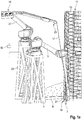
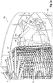
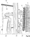
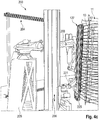
- FIG. 1a a system 1 according to a first embodiment of the invention is shown.
- the plant 1 has a first handling robot 3, which is designed to form helically arranged stiffening elements 27 by means of corresponding bending means.
- the first handling robot 3 has a working head with a bending device 19.
- the first handling robot 3 is according to FIGS. 1a . b arranged on a support structure 5. This can be a pedestal like in FIGS. 1a . b , or another support structure, as shown for example in one of the further embodiments.
- the system 1 has a receiving area 7.
- the receiving area 7 is adapted to receive a gripping device 11.
- the gripping device 11 has coupling means, for example in the form of hook-shaped arithmetic arms, on each of which substantially horizontally oriented ring elements 13 are arranged.
- the receiving area 7 is arranged on a preferably rotatable platform 9.
- the platform 9 is preferably connected in terms of data to an electronic control unit, so that the rotation can be coordinated according to the work progress of the handling robots 3 and 21 by means of the electronic control unit.
- the first handling robot 3 is connected, among other things, to a feed unit 15 by means of an electronic control device and cooperates therewith so that the feed unit 15 can supply the handling robot 3 with an endless material 17 for producing the helical stiffening elements 27.
- the system 1 also has a second handling robot 21, which has a working head 25 with a connecting means, for example designed as a welding wheel.
- the second handling robot 21 is preferably is also connected to the electronic control unit and cooperates with the first handling robot 3 and the platform 9 to connect the stiffening elements 27 produced with the substantially horizontally oriented ring elements 13, which are held by the gripping device 11.
- the second handling robot 21 may, for example, be arranged on a support structure 23 adjacent to the receiving area 7, or on an alternative support structure together with the first handling robot, as shown for example in the following embodiments.
- the first handling robot 3 is multi-axially movable to allow the working head 19 to create bends in the continuous material 17 so as to form the substantially vertically oriented stiffening elements 27.
- the working head 19 is for this purpose also reconfigurable and implementable, as in FIG. 1b is shown, and in particular in the FIGS. 2a to 2g is pictured.
- the system also has an electronic control device 10 for the coordinated control of the handling robots 3, 21 and the platform 9.
- FIGS. 2a to 2g a section of the system 1 according to the first embodiment is shown, in which the working head 19 of the first handling robot 3 is shown in operation.
- a first substantially vertically aligned stiffening element 27 has already been created adjacent to the ring elements 13 in the receiving area 7.
- the working head 19 has a base body 29, on which a plurality of deflection rollers 31a, b, c (FIG. FIGS. 2c to 2g ) are arranged.
- FIG. 2a a first bend has been created for a stiffening element 27.
- the endless material 17 is based on the state according to FIG. 2a in FIG. 2b further deformed by adding another bend.
- the first handling robot 3 has performed a corresponding pivoting movement about a working axis b.
- the first handling robot 3 sets according to the state FIG. 2b from short and swings the hull of the handling robot 3 to the outside, so that the first Handling robot 3 when further guiding the endless material 17 upwards to the next produced bend not collided.
- the trained with bending means in the form of a bending device working head 19 of the first handling robot 3 has adjustable guide rollers 31a, b, c, which are arranged on the base body 29.
- An exemplary conversion of the role positions, associated with a transfer movement of the working head 19 are in the FIGS. 2c to 2g illustrated.
- Figure 2c is the working head 19 on the first handling robot 3 initially still in engagement with the endless material 17.
- the working head 19 is pivoted about an axis c on the first handling robot 3 in the direction of the arrow 33, so that the rollers 31a, b, c are disengaged from the endless material 17.
- FIG. 2e results, the positions of the rollers 31a and 31c are changed in a first direction, while the deflection roller 31b arranged between the deflection rollers 31a, c is displaced in the opposite direction.
- the repositioning of the deflection rollers 31a, b, c can be either stepless or rasterized, for example, by converting into dedicated openings.
- FIG. 2f the working head 19 is pivoted again in the direction of the arrow 35 about the axis c, so that the deflection rollers 31a, b, c are again in engagement with the endless material 17.
- Figure 2g displayed.
- the rotational position of the main body 29 is constant relative to the first handling robot 3. It is optional but also possible to pivot the main body 29 of the working head 19 about an axis a, such as in the comparison of FIG. 2b apparently with 2c.
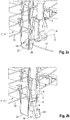
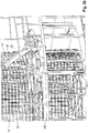
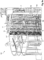
- FIGS. 3a . b schematically show a section of a plant 100 according to a second embodiment of the invention.
- the essential inventive features are the same as in the first embodiment.
- the type of arrangement of a first handling robot 103 of the system 100 and a second handling robot 121 of the system 100 are in Principle can be exchanged or combined with the type of arrangement in system 1.
- the first handling robot 103 of the installation 100 has on its working head 119 a gripping device with which the handling robot 103 can grasp stiffening elements 127 from the inside and hold them non-slip.
- the stiffening elements 127 according to the second embodiment are separate, preferably closed, bracket.
- the first handling robot 103 is adapted to remove the bow-shaped stiffening elements 127 with the working head 119 designed as a gripping device from a storage, to bring into abutment with the ring elements 13 on the gripping device 11 of the system 100, and to put there until the second Handling robot 121 with its trained as a welding device working head 125, for example, as a welding wheel, the stiffening elements 127 has connected to the ring elements 13.
- the first handling robot 103 and the second handling robot 121 are according to FIG FIGS. 3a . b on a gripping device 11 and the (not shown) rotatable platform 9 ( FIG. 1a ) surrounding annular platform 105.
- support structures such as in FIG. 1a . b be selected, just as in the first embodiment of Appendix 1 in the FIGS. 1a . b a support structure such as the platform 105 shown here could be selected.
- FIGS. 4a to 4c The exact execution of the storage is not shown in this embodiment for reasons of clarity. It may, for example, a storage such as the storage 204 from the embodiment of the illustrated below FIGS. 4a to 4c be.
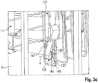
- the second handling robot 121 In the state according to FIG. 3a the second handling robot 121 is positioned such that a stiffening element 127 is connected to one of the ring elements 13 in the upper region of the reinforcement cage to be created.
- the second handling robot 121 is positioned so that the working head 125 can connect the stiffening element 127 in a lower region of the reinforcing cage to be produced in the gripping device 11 with a ring element or, alternatively, performs a welding on the stiffening element 127 itself.
- the first handling robot 103 holds the stiffening element 127 non-slip in position during these operations. This is done by means of pivotable coupling members which are arranged at opposite ends of the working head 119.
- Figure 3c shows coupling link 141, although obscured by the working head 125 of the second handling robot 121. The coupling member with its components is also explained in more detail in an embodiment to be discussed below also.
- the coupling member 141 which is in Figure 3c is seen, at a first end on a guide roller 145, which is adapted to be inserted into the bend, thus corner, a stiffening element 127 and to detect the stiffening element there.
- a support portion 147 is arranged, which is adapted to exert a pivoting of the coupling member 141 together with the guide roller 145 an expanding force on the stiffening member 127 which is large enough to the stiffening member 127 non-slip to be able to hold.
- the coupling member 141 is preferably movable by means of an actuator 143.
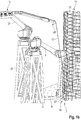
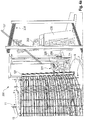
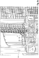
- FIGS. 4a to 4c a plant 200 for the production of reinforcement cages according to a third embodiment is shown.
- the third embodiment is structurally very similar to the second embodiment, it is therefore only pointed to constructive differences.
- the system 200 has a height-adjustable portal 206, on which a second handling robot 221 is arranged to be vertically movable.
- a first handling robot 203 is mounted separately on the second handling robot 221 on a support structure 205.
- the system 200 has a storage 204 of stiffening elements 127.
- the first handling robot 203 is configured to remove these stiffening elements 127 from the storage 204 and to place them against the ring elements 13, which are held on the gripping device 11 and arranged in the receiving area 7 on a rotatable platform 9.
- This removal process is exemplified.
- FIG. 4b that the same plant 200 out FIG. 4a shows in a different angle, the first handling robot 203 has brought a previously removed stiffening element 127 into abutment with the ring elements 13 on the gripping device 11.
- the second handling robot 221 is adapted to move along the portal 206 in height to the appropriate location, and then bring a working head 225 in position, which connects the stiffening element 127 with a portion of a ring element 13 at different heights along the Produces reinforcement cage.
- the substantially horizontally oriented ring members 13 were the ring members for a so-called inner helix of the reinforcing cage to be manufactured. It is also within the scope of the invention that these ring elements represent a so-called outer helix, in which case the stiffening elements could then be arranged on the inside with reference to these ring elements. Corresponding changes to the handling robot positions are not shown in all combinations for reasons of clarity.
- an inner helix for the substantially horizontally oriented ring elements 13 it is in the context of another embodiment, which is to be understood as an addition to all embodiments previously shown, but by way of example only with reference to the embodiment of the FIGS. 3a to 3c is imaged, provided that the substantially horizontally oriented ring elements 13 represent a first set of ring elements.
- an automatic winding unit 150 is provided in the system 100, which is adapted to a second set of substantially horizontally oriented on a relative to the first set of ring elements opposite side of the stiffening elements 127 (or the helically shaped stiffening elements 27 in the first embodiment) To provide ring elements 14.
- the winding unit 150 has a guide device 153, which is adapted to a continuous material, which is the same Endless material for the helically formed stiffening elements 27 of FIGS. 1a to 2g may be, annularly or helically around the stiffening elements 127 to lay around.
- the winding unit 150 is moved in a height-adjustable manner on a gantry 151, while the platform 9 is rotated about a vertically aligned axis e together with the gripping device 11, the ring elements 13 and the stiffening elements 127.
- the continuous material is preferably provided by a supply means in the form of a storage 155, which can hold a drum-like winding of the continuous material.
- the guide device 153 may have a plurality of guide rollers, which allow a targeted dispensing of the continuous material for forming the rings 14.
- the winding unit 150 is preferably connected in terms of data to a central electronic control unit, for example the one mentioned above, which coordinates the work of the various system components such as handling robot, winding unit and rotatable platform. This control unit is in FIG. 1a indicated.
- the winding unit which in the FIGS. 5a . b is shown, for example, be the feeder 15, which in the embodiment of the FIGS. 1a to 2g is used to provide the continuous material 17.
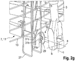
- the plant 1 according to the embodiment of the FIGS. 1a to 2g preferably has another handling robot 61.
- the handling robot 61 is in particular designed identically to the first handling robot 103 from the exemplary embodiment of FIG FIGS. 3a to c.
- this handling robot 61 can also be used in the system 1 with advantage, by engaging it to stabilize the already formed helical stiffening elements 27 in this and holds as long as non-slip until the second handling robot 21 has performed the required connection work between the stiffening elements 27 and the ring elements 13.
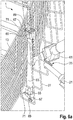
- FIGS. 6b to c are regarding the in FIG. 6a visible, designed as a gripping device working head 63 of the handling robot 61 further details shown in the working head 119 of the embodiment of FIGS. 3a to c for the sake of simplicity of illustration just as in the embodiment of FIGS. 4a to c were omitted.
- the coupling device here reference numeral 67 instead of reference numeral 141, is arranged movably on the working head 63 by means of an actuator 65.
- the support section now has the reference numeral 71, and the guide roller the reference numeral 69.
- the operation of the coupling member is exemplified in the FIGS. 6b, c shown.
- the gripping device 63 in the in FIG. 6a shown state spent.
- FIG. 6b shown coupling member 67 in the "inner region" of a corner of a coil of the stiffening elements 27. From this position, a piston rod 75 is extended in the direction of arrow 73 by means of the actuator 65. This is after FIG. 6c As a result, the guide roller 69 of the coupling member abuts against an end portion 27a of the stiffening member 27 and, with continued movement of the piston rod 75, rolls in the direction of one of the bending corners. In FIG. 6c the guide roller 69 has arrived in the bend corner 27b.
- the piston rod 75 has moved so far by means of the actuator 65 that the support section 71 arranged at the opposite end of the coupling element 67, relative to the guide roller 69, is in contact with a substantially vertical section 27c of the stiffening element 27.
- the actuator 65 is able, by further pushing out of the piston rod 75, to exert an expanding force on the stiffening element 27, by means of which it is fixed and stabilized.
- connecting the stiffening elements in the immediate vicinity of the held stiffening element 27, including the stiffening element 27 itself, by the second handling robot 21 is possible.
Description
Die vorliegende Erfindung betrifft eine Anlage zur Herstellung von Bewehrungskörben für Turmsegmente von Windenergieanlagen, wobei ein Bewehrungskorb jeweils im Wesentlichen horizontal ausgerichtete Ringelemente und im Wesentlichen vertikal ausgerichtete Versteifungselemente aufweist (siehe z.B. die gattungsgemäße
In der Herstellung solcher Turmsegmente wird zunächst der Bewehrungskorb hergestellt und sodann mit Beton in dafür vorgesehene Formen umfüllt und ausgehärtet.In the production of such tower segments, first the reinforcement cage is produced and then filled with concrete in designated forms and cured.
Bei bekannten Vorrichtungen zur Herstellung von Bewehrungskörben für Turmsegmente ist eine Tragstruktur vorgesehen, weiche eine Vielzahl von Stangen, sogenannten Rechen, hält. Diese Stangen weisen jeweils Aufnahmen zur Aufnahme von Betonstahldraht auf, wobei der Betonstahl um die Tragstruktur herum geführt wird, bzw. die Tragstruktur in Rotation versetzt wird um Ringelemente zu bilden. Diese Ringelemente werden mit im Wesentlichen orthogonal zu den Ringen oder im Wesentlichen vertikal verlaufenden bügelförmigen (Stahl-) Versteifungselementen verknüpft, wodurch ein gitterförmiger Bewehrungskorb entsteht.In known devices for the production of reinforcing baskets for tower segments, a supporting structure is provided which holds a plurality of bars, so-called rakes. These rods each have receptacles for receiving reinforcing steel wire, wherein the reinforcing steel is guided around the supporting structure, or the supporting structure is set in rotation to form ring elements. These ring elements are associated with substantially orthogonal to the rings or substantially vertically extending bow-shaped (steel) stiffening elements, whereby a grid-shaped reinforcing cage is formed.
Der Betonstahldraht wird entweder in einer Kreisbewegung um eine stationäre Tragstruktur herumgeführt oder, was bevorzugt ist, befindet sich in einer stationären Zuführeinrichtung und wird von der rotatorisch antreibbaren Tragstruktur aus der Aufnahme gezogen und legt sich infolge der Rotationsbewegung der Tragstruktur ringförmig um diese herum. Während der gesamten Zeit wird die Form der ringförmigen Stahllitzen von der Tragstruktur und den Stangen mittels einer Vielzahl von Speichen stabilisiert, die sich zwischen der Tragstruktur und den Stangen erstrecken. Zum Entfernen der Bewehrungskörbe aus der Vorrichtung müssen die Speichen bei bekannten Systemen jeweils zurückgerüstet oder die stabilisierenden Stangen einzeln und manuell aus dem fertigen Korb ausgehakt werden.The reinforcing steel wire is either guided in a circular motion around a stationary support structure or, which is preferred, is located in a stationary feeder and is pulled out of the receptacle by the rotatably driven support structure and surrounds it annularly as a result of the rotational movement of the support structure. Throughout the time, the shape of the annular steel strands is stabilized by the support structure and the rods by means of a plurality of spokes extending between the support structure and the rods. To remove the reinforcement cages from the device, the spokes must be respectively retrofitted in known systems or the stabilizing rods individually and manually unhooked from the finished basket.
Je nach Größe der herzustellenden Turmsegmente weisen bereits die Bewehrungskörbe ein beträchtliches Gewicht und, dem Turmsegment entsprechend, beträchtliche Ausmaße auf. Beispielsweise weist ein Bewehrungskorb für das unterste, also größte Turmsegment einer Windenergieanlage des Typs E126 der Firma ENERCON einen Durchmesser von ca. 14m, eine Höhe von ca. 3,7m und ein Gewicht von ca. 8,5t auf. Aufgrund ihrer gitterartigen Struktur und der enormen Ausmaße sind Bewehrungskörbe im Fertigungsbetrieb nur schwer mit konventionellen Kransystemen handhabbar.Depending on the size of the tower segments to be produced, the reinforcing baskets already have a considerable weight and, according to the tower segment, considerable dimensions. For example, a reinforcement cage for the lowest, so the largest tower segment of a wind turbine of the type E126 ENERCON has a diameter of about 14m, a height of about 3.7m and a weight of about 8.5t. Due to their lattice-like structure and their enormous dimensions, reinforcement baskets are difficult to handle in manufacturing operations with conventional crane systems.
Aus
Neben dem Handhaben der Bewehrungskörbe besteht bei den bekannten Fertigungsumgebungen allerdings der Bedarf, die Verknüpfung der im Wesentlichen vertikalen Elemente mit den im Wesentlichen horizontalen Ringelementen der Bewehrungskörbe effizienter zu gestalten, und diese gleichzeitig mit der vorstehend bezeichneten bekannten Greifeinrichtung handhaben zu können.In addition to handling the reinforcing cages, however, there is a need in the known manufacturing environments to make the linking of the substantially vertical elements with the substantially horizontal ring elements of the reinforcing cages more efficient, and to be able to handle them simultaneously with the known gripping device described above.
Der Erfindung lag somit die Aufgabe zugrunde, eine Anlage der eingangs bezeichneten Art anzugeben, die eine effiziente Herstellung der Bewehrungskörbe gewährleistet. Insbesondere war es auch Aufgabe der zugrundeliegenden Erfindung, jene Anlage in Kombination mit beispielsweise der vorbezeichneten bekannten Greifeinrichtung gemeinsam verwenden zu können.The invention was therefore based on the object to provide a system of the type described, which ensures an efficient production of the reinforcement cages. In particular, it was also the task of the underlying Invention to be able to use those plant in combination with, for example, the aforementioned known gripping device together.
Die Erfindung löst die ihr zugrundeliegende Aufgabe mit einer Anlage gemäß Anspruch 1 oder 2.The invention solves the underlying task with a system according to claim 1 or 2.
Der Erfindung liegt die Erkenntnis zugrunde, dass durch die Verwendung eines ersten und zweiten Handhabungsroboters die Anzahl der manuellen Arbeiten reduziert werden kann, die Arbeitssicherheit insgesamt erhöht wird, und eine verbesserte Arbeitsplanung ermöglicht wird. Es hat sich überraschend herausgestellt, dass trotz des komplexen Anlagenaufbaus und der vielen Freiheitsgrade im Betrieb ein zeiteffizientes Herstellen von Bewehrungskörben möglich ist.The invention is based on the recognition that by using a first and second handling robot, the number of manual tasks can be reduced, the total work safety is increased, and improved work planning is made possible. It has surprisingly been found that, despite the complex system structure and the many degrees of freedom in operation, a time-efficient production of reinforcement cages is possible.
Gemäß der vorliegenden Erfindung können verschiedene Arten von Versteifungselementen ausgebildet werden, um Teil des Bewehrungskorbs zu werden. Gemäß einem ersten Aspekt sind die Versteifungselemente aus einem wendelförmig gebogenen Endlosmaterial ausgebildet. Besonders bevorzugt sind die Versteifungselemente aus einem einzigen, entlang des Umfangs der Ringelemente vollständig umlaufenden wendelförmig gebogenen Stahldraht ausgebildet. Diese Struktur wird auch als Steher-Helix bezeichnet. Eine solche Ausgestaltung der Versteifungselemente hat den Vorteil, dass eine separate und damit mit Transportaufwand verbundene Biege- und Schweißeinrichtung zur Bereitstellung der Versteifungselemente entfallen kann.According to the present invention, various types of stiffening elements can be formed to become part of the reinforcing cage. According to a first aspect, the stiffening elements are formed from a helically bent endless material. Particularly preferably, the stiffening elements are formed from a single, along the circumference of the ring elements completely encircling helically bent steel wire. This structure is also called Steher-Helix. Such a configuration of the stiffening elements has the advantage that a separate and thus associated with transport effort bending and welding device can be omitted to provide the stiffening elements.
Der erste Handhabungsroboter ist somit dazu eingerichtet, diese Struktur entlang der im Wesentlichen horizontalen Ringelemente auszubilden und anzuordnen.The first handling robot is thus configured to form and arrange this structure along the substantially horizontal ring elements.
Gemäß diesem ersten Aspekt weist der erste Handhabungsroboter Biegemittel auf, und wirkt mit einer Zuführeinheit zusammen, die den Biegemitteln das Endlosmaterial zuführt, wobei die Biegemittel dazu eingerichtet sind, das zugeführte Endlosmaterial derart zu biegen, dass die Versteifungsmittel daraus wendeiförmig ausgebildet werden.According to this first aspect, the first handling robot comprises bending means and cooperates with a feed unit which feeds the continuous material to the bending means, the bending means being arranged to bend the fed continuous material in such a way that the stiffening means are helically formed therefrom.
Die Biegemittel weisen vorzugsweise Umlenkrollen auf, zwischen welchen das Endlosmaterial hindurchgeführt wird, wobei die Positionen der Umlenkrollen relativ zueinander veränderbar sind. Vorzugsweise sind die Positionen der Umlenkrollen relativ zueinander derart veränderbar, dass unterschiedliche Biegeradien und Biegerichtungen in das Endlosmaterial eingebracht werden können.The bending means preferably have deflection rollers, between which the endless material is guided, wherein the positions of the deflection rollers are variable relative to each other. Preferably, the positions of the deflection rollers relative to each other are variable so that different bending radii and bending directions can be introduced into the continuous material.
Die Anordnung der Umlenkrollen kann beispielsweise nach Art von Rohrbiegewerkzeugen ausgeführt sein.The arrangement of the pulleys can be performed for example in the manner of pipe bending tools.
In einer anderen bevorzugten Ausführungsform sind die Biegemittel stationär an der Korbherstellungsanlage angeordnet, wobei ein Handhabungsroboter vorzugsweise nicht das Biegen an sich sondern nur die Handhabung des gebogenen Betonstahls übernimmt.In another preferred embodiment, the bending means are arranged stationarily on the basket manufacturing plant, wherein a handling robot preferably does not take over the bending per se but only the handling of the bent reinforcing steel.
Gemäß einem zweiten Aspekt der Erfindung sind die Versteifungselemente als separate, vorzugsweise geschlossene, Bügel ausgebildet. Diese Ausgestaltung hat den Vorteil, dass das Anordnen der einzelnen Versteifungselemente um die Ringelemente herum flexibler gehandhabt werden kann und der Handhabungsprozess einfacher beherrschbar ist. In der Ausgestaltung gemäß diesem Erfindungsaspekt werden die Versteifungselemente in einem separaten Herstellungsverfahren vorgefertigt und sodann in größeren Ansammlungen bevorratet.According to a second aspect of the invention, the stiffening elements are designed as separate, preferably closed, stirrups. This embodiment has the advantage that the arrangement of the individual stiffening elements around the ring elements can be handled more flexibly and the handling process is easier to control. In the embodiment according to this aspect of the invention, the stiffening elements are prefabricated in a separate manufacturing process and then stored in larger collections.
Gemäß diesem zweiten Aspekt weist der erste Handhabungsroboter Greifmittel zum rutschsicheren Fassen und Entnehmen der Versteifungselemente von einer Bevorratungseinheit auf. Unter rutschsicher wird hierbei verstanden, dass die Greifmittel die Versteifungselemente entweder formschlüssig ergreifen, oder derart kraftschlüssig, dass unter Berücksichtigung der bei der Bewegung der Handhabungsroboter zu erwartenden Beschleunigungen Haftreibung, aber keine Gleitreibung zwischen den Greifmitteln und den Versteifungselementen auftritt, und selbstverständlich auch kein Lösen der Greifmitteln von den Versteifungselementen.According to this second aspect, the first handling robot has gripping means for non-slip grasping and removal of the stiffening elements from a storage unit. Non-slip is here understood that the gripping means engage the stiffening elements either positively, or such a force-locking that under consideration of the movement of the handling robot accelerations expected friction, but no sliding friction between the gripping means and the stiffening elements occurs, and of course no release of Gripping means of the stiffening elements.
Vorzugsweise sind die Greifmittel dazu eingerichtet, das Versteifungselement an gegenüberliegenden Enden des Versteifungselements in jeweils mindestens einer Ecke von innen zu ergreifen.Preferably, the gripping means are adapted to grasp the stiffening element at opposite ends of the stiffening element in at least one corner from the inside.
Gemäß einer weiteren bevorzugten Ausführungsform weisen die Greifmittel ein erstes und zweites schwenkbares Koppelglied auf, welches dazu eingerichtet ist, das Versteifungselement in jeweils mindestens einer Ecke mittels Verschwenken zu ergreifen.According to a further preferred embodiment, the gripping means on a first and second pivotable coupling member which is adapted to take the stiffening element in each case at least one corner by pivoting.
Die Koppelglieder weisen vorzugsweise jeweils eine Führungsrolle zum Greifen des Versteifungselements, vorzugsweise von innen, in einer Ecke auf, sowie vorzugsweise einen Stützabschnitt oder eine weitere Rolle an einem gegenüberliegenden Ende des Koppelglieds. Der Stützabschnitt oder die weitere Rolle sind vorzugsweise jeweils derart angeordnet, dass beim Verschwenken des Koppelglieds eine ausreichende Spreizkraft auf das Versteifungselement ausgeübt wird, dass der erste Handhabungsroboter das Versteifungselement rutschsicher heben, senken und verfahren kann.The coupling links preferably each have a guide roller for gripping the stiffening element, preferably from the inside, in a corner, and preferably a support section or a further roller at an opposite end of the coupling link. The support section or the further roller are preferably each arranged such that upon pivoting of the coupling member a sufficient spreading force is exerted on the stiffening element, that the first handling robot can lift, lower and move the stiffening element non-slip.
Die Erfindung wird vorzugsweise weitergebildet, indem die Anlage eine elektronische Steuereinheit aufweist, welche dazu eingerichtet ist, den ersten und zweiten Handhabungsroboter zum koordinierten Bereitstellen der Versteifungselemente und zum Verbinden der Versteifungselemente mit den Ringelementen zu steuern. Vorzugsweise weist die elektronische Steuereinheit hierzu einen oder mehrere rechnergestützte Arbeitsplätze auf, die zum Einlesen und Verarbeiten einer virtuellen Darstellung des herzustellenden Bewehrungskorbes und der den Bewehrungskorb herstellenden Anlage inklusive der Handhabungsroboter eingerichtet sind. Die virtuelle Darstellung kann in Form von CAD-Daten und/oder CAD/CAM-Daten bereitgestellt sein. Vorzugsweise sind in der elektronischen Steuereinheit Datensätze hinterlegt, die ein bestimmtes Bewegungsmuster der Handhabungsroboter mit einem jeweils herzustellenden Typus eines Bewehrungskorbes verknüpfen. Bewehrungskörbe haben je nachdem, für welches Turmsegment sie verwendet werden sollen, unterschiedliche Größen. Diese können beispielsweise in Datenspeichern hinterlegt werden, und die elektronische Steuereinheit ist vorzugsweise dazu eingerichtet, auf diese zuzugreifen, die entsprechenden Datensätze auszulesen und in Arbeitsanweisungen für den ersten und zweiten Handhabungsroboter umzusetzen.The invention is preferably further developed in that the system has an electronic control unit which is set up to control the first and second handling robots for coordinated provision of the stiffening elements and for connecting the stiffening elements to the ring elements. For this purpose, the electronic control unit preferably has one or more computer-assisted workstations which are set up for reading in and processing a virtual representation of the reinforcing cage to be produced and the installation producing the reinforcing cage, including the handling robots. The virtual representation may be provided in the form of CAD data and / or CAD / CAM data. Preferably, records are stored in the electronic control unit, which records a specific movement pattern of the handling robot with a respective type of a Link reinforcing basket. Rebar baskets have different sizes depending on which tower segment they are to be used for. These can for example be stored in data stores, and the electronic control unit is preferably configured to access them, to read out the corresponding data records and to convert them into work instructions for the first and second handling robots.
In einer bevorzugten Ausführungsform der Erfindung ist der Aufnahmebereich auf einer drehbaren Plattform angeordnet. Vorzugsweise sind der erste und zweite Handhabungsroboter ortsfest benachbart zu der Plattform angeordnet, und/oder vorzugsweise radial zum Mittelpunkt der Plattform verstellbar. Indem die Handhabungsroboter benachbart zu der vorzugsweise drehbaren Plattform angeordnet sind, wird eine verbesserte Platzausbeute der Herstellungsumgebung erzielt. Bewehrungskörbe für Turmsegmente sind im Wesentlichen zylindrisch oder kegelstumpfrohrförmig ausgebildet, so dass eine Rotation der Bewehrungskörbe auf der Aufnahmeplattform keinen zusätzlichen Platzbedarf in irgendeine Richtung erfordert.In a preferred embodiment of the invention, the receiving area is arranged on a rotatable platform. Preferably, the first and second handling robots are arranged stationarily adjacent to the platform, and / or preferably radially adjustable to the center of the platform. By locating the handling robots adjacent to the preferably rotatable platform, an improved space efficiency of the manufacturing environment is achieved. Reinforcing baskets for tower segments are substantially cylindrical or frusto-conical shaped so that rotation of the reinforcing baskets on the receiving platform does not require additional space in any direction.
Gemäß einer weiteren bevorzugten Ausführungsform ist der Aufnahmebereich zum Zusammenwirken mit einer Greifeinrichtung zum Handhaben eines Bewehrungskorbs eingerichtet. Die Greifeinrichtung ist vorzugsweise gemäß der
Weiter vorzugsweise ist der erste Handhabungsroboter dazu eingerichtet, die Versteifungselemente im Wesentlichen vertikal ausgerichtet mit den Ringelementen in Anlage zu bringen. Hierbei ist es unbeachtlich, wenn einzelne Ringelemente nicht in Anlage mit den Versteifungselementen gebracht werden. Maßgeblich ist es, dass diejenigen Versteifungselemente und Ringelemente miteinander in Anlage gebracht werden, an deren Schnittstellen nachfolgend durch den zweiten Handhabungsroboter eine Verbindung herbeigeführt werden soll. Unter der Angabe "im Wesentlichen vertikal" wird erfindungsgemäß auch ein solcher Neigungswinkel zur Vertikalen verstanden, wie er beispielsweise durch einen schrägen, wendelförmigen Verlauf entstehen kann, beispielsweise in einem Bereich von ± 1 bis 10°.Further preferably, the first handling robot is adapted to bring the stiffening elements substantially aligned with the ring elements in abutment. It is irrelevant if individual ring elements are not brought into contact with the stiffening elements. It is decisive that those stiffening elements and ring elements are brought into abutment with one another, at the interfaces of which a connection is subsequently to be brought about by the second handling robot. The term "substantially vertical" is understood according to the invention as such an inclination angle to the vertical, as it may arise, for example, by an oblique, helical course, for example in a range of ± 1 to 10 °.
Gemäß einer weiteren bevorzugten Ausführungsform der Erfindung weist der zweite Handhabungsroboter einen schwenkbaren Arbeitskopf auf, an welchem ein Verbindemittel angeordnet ist, ausgewählt aus der Liste bestehend aus:
- Klebstoffabgabevorrichtung,
- Schweißvorrichtung,
- Lötvorrichtung,
- Vorrichtung zum automatischen Verdrillen von Metalldrähten.
- Adhesive dispenser
- Welder,
- soldering apparatus,
- Device for automatically twisting metal wires.
Die Vorrichtung zum automatischen Verdrillen von Metalldrähten ist vorzugsweise ausgebildet wie bekannt aus
Die obigen Ausführungen haben jeweils Bezug genommen auf Ringelemente im Allgemeinen. Diese können als ein erster Satz Ringelemente aufgefasst werden, wenn in einer bevorzugten Ausführungsform die Anlage einen dritten Handhabungsroboter zum Bereitstellen eines zweiten Satzes im Wesentlichen horizontal ausgerichteter, vorzugsweise äußerer, Ringelemente aufweist, wobei die Ringelemente als separate, vorzugsweise geschlossene, Ringe ausgebildet sind, oder aus einem wendelförmig gebogenen Endlosmaterial ausgebildet sind. Die elektronische Steuereinheit ist vorzugsweise ebenso dazu eingerichtet, auch den dritten Handhabungsroboter koordiniert mit dem ersten und zweiten Handhabungsroboter zu steuern, insbesondere auf Basis einer entsprechenden virtuellen Darstellung.The above statements have each referred to ring elements in general. These can be considered as a first set of ring elements, if in a preferred embodiment the system comprises a third handling robot for providing a second set of substantially horizontally oriented, preferably outer, ring elements, wherein the ring elements are formed as separate, preferably closed, rings are formed from a helically bent endless material. The electronic control unit is preferably likewise configured to also control the third handling robot coordinated with the first and second handling robots, in particular based on a corresponding virtual representation.
Vorzugsweise weist der dritte Handhabungsroboter eine Führungseinrichtung, vorzugsweise mit einer oder mehreren Führungsrollen, auf und wirkt mit einer Zuführeinheit zusammen, die der Führungseinrichtung das Endlosmaterial zuführt, wobei die Führungseinrichtung dazu eingerichtet ist, das zugeführte Endlosmaterial derart zu führen, dass der zweite Satz Ringelemente wendelförmig ausgebildet wird.Preferably, the third handling robot has a guide device, preferably with one or more guide rollers, and cooperates with a feed unit, which guides the endless material feeds, wherein the guide means is adapted to guide the supplied endless material such that the second set of ring elements is formed helically.
Der zweite Handhabungsroboter ist vorzugsweise ferner dazu eingerichtet, auch den zweiten Satz Ringelemente mit den Versteifungselementen zu verbinden.The second handling robot is preferably further configured to also connect the second set of ring elements to the stiffening elements.
Die elektronische Steuereinheit ist vorzugsweise dazu eingerichtet, den zweiten und dritten Handhabungsroboter, vorzugsweise sämtliche Handhabungsroboter der Anlage, zum koordinierten Bereitstellen des zweiten Satz Ringelemente und Verbinden der Versteifungselemente mit dem zweiten Satz Ringelemente zu steuern. Hierbei wird vorzugsweise auf die gleichen Mittel und Ressourcen zurückgegriffen wie in Bezug auf den ersten und zweiten Handhabungsroboter.The electronic control unit is preferably configured to control the second and third handling robots, preferably all handling robots of the system, for coordinately providing the second set of ring elements and connecting the stiffening elements to the second set of ring elements. In this case, the same resources and resources are preferably used as with respect to the first and second handling robots.
Die Erfindung wird im Folgenden unter Bezugnahme auf die beigefügten Figuren anhand bevorzugter Ausführungsbeispiele näher erläutert. Hierbei zeigen:
- Figuren 1a, b
- eine schematische Teilansicht einer Anlage gemäß einem ersten Ausführungsbeispiel,
- Figuren 2a-g
- unterschiedliche Arbeitsstellungen des ersten Handhabungsroboters gemäß dem ersten Ausführungsbeispiel,
- Figuren 3a-c
- unterschiedliche schematische Teilansichten einer Anlage gemäß einem zweiten Ausführungsbeispiel,
- Figuren 4a-c
- unterschiedliche schematische Teilansichten einer Anlage gemäß einem dritten Ausführungsbeispiel,
- Figuren 5a,b
- unterschiedliche Arbeitsstellungen und schematische Teilansichten eines dritten Handhabungsroboters, exemplarisch für das zweite Ausführungsbeispiel, und
- Figuren 6a-c
- unterschiedliche Arbeitsstellungen eines weiteren Handhabungsroboters für eine Anlage gemäß einem der Ausführungsbeispiele, exemplarisch am ersten Ausführungsbeispiel abgebildet.
- FIGS. 1a, b
- a schematic partial view of a system according to a first embodiment,
- Figures 2a-g
- different working positions of the first handling robot according to the first embodiment,
- FIGS. 3a-c
- different schematic partial views of a system according to a second embodiment,
- FIGS. 4a-c
- different schematic partial views of a system according to a third embodiment,
- FIGS. 5a, b
- different working positions and schematic partial views of a third handling robot, exemplary of the second embodiment, and
- Figures 6a-c
- different working positions of another handling robot for a system according to one of the embodiments, exemplified in the first embodiment.
In
Die Anlage 1 weist einen Aufnahmebereich 7 auf. Der Aufnahmebereich 7 ist dazu eingerichtet, eine Greifeinrichtung 11 aufzunehmen. Die Greifeinrichtung 11 weist Kopplungsmittel, beispielsweise in Form von hakenförmigen Rechenarmen auf, auf denen jeweils im Wesentlichen horizontal ausgerichtete Ringelemente 13 angeordnet werden. Der Aufnahmebereich 7 ist auf einer vorzugsweise drehbaren Plattform 9 angeordnet. Die Plattform 9 ist vorzugsweise datenleitend mit einer elektronischen Steuereinheit verbunden, so dass die Rotation entsprechend des Arbeitsfortschritts der Handhabungsroboter 3 und 21 mittels der elektronischen Steuereinheit koordiniert erfolgen kann.The system 1 has a receiving
Der erste Handhabungsroboter 3 ist mittels einer elektronischen Steuereinrichtung unter anderem mit einer Zuführeinheit 15 verbunden und wirkt mit dieser zusammen, damit die Zuführeinheit 15 dem Handhabungsroboter 3 ein Endlosmaterial 17 zum Herstellen der wendelförmigen Versteifungselemente 27 zuführen kann.The
Die Anlage 1 weist ferner einen zweiten Handhabungsroboter 21 auf, welcher einen Arbeitskopf 25 mit einem Verbindemittel, beispielsweise ausgebildet als Schweißrad, aufweist. Der zweite Handhabungsroboter 21 ist vorzugsweise ebenfalls mit der elektronischen Steuereinheit verbunden und wirkt koordiniert mit dem ersten Handhabungsroboter 3 und der Plattform 9 zusammen, um die erzeugten Versteifungselemente 27 mit den im Wesentlichen horizontal ausgerichteten Ringelementen 13, die von der Greifeinrichtung 11 gehalten werden, zu verbinden. Der zweite Handhabungsroboter 21 kann beispielsweise auf einer Tragstruktur 23 benachbart zu dem Aufnahmebereich 7 angeordnet sein, oder auf einer alternativen Tragstruktur gemeinsam mit dem ersten Handhabungsroboter, wie beispielsweise in den folgenden Ausführungsbeispielen gezeigt wird.The system 1 also has a
Der erste Handhabungsroboter 3 ist mehrachsig bewegbar, um den Arbeitskopf 19 zum Erzeugen von Biegungen in dem Endlosmaterial 17 derart zu ermöglichen, dass die im Wesentlichen vertikal ausgerichteten Versteifungselemente 27 entstehen. Der Arbeitskopf 19 ist hierzu auch rekonfigurierbar und umsetzbar, wie in
Die Anlage weist ferner eine elektronische Steuereinrichtung 10 zum koordinierten Steuern der Handhabungsroboter 3, 21 und der Plattform 9 auf.The system also has an
In den
Der mit Biegemitteln in Form einer Biegeeinrichtung ausgebildete Arbeitskopf 19 des ersten Handhabungsroboters 3 weist verstellbare Umlenkrollen 31a, b, c auf, die an dem Grundkörper 29 angeordnet sind. Eine beispielhafte Umstellung der Rollenpositionen, verbunden mit einer Umsetzbewegung des Arbeitskopfes 19 sind in den
In
Die
Die genaue Ausführung der Bevorratung ist in diesem Ausführungsbeispiel nicht dargestellt aus Gründen der Übersichtlichkeit. Sie kann beispielsweise eine Bevorratung wie die Bevorratung 204 aus dem nachfolgend dargestellten Ausführungsbeispiel der
Im Zustand gemäß
Das Koppelglied 141, was in
Das Koppelglied 141 ist vorzugsweise mittels eines Aktuators 143 verfahrbar.The
In den
Bei den hierin vorstehend gezeigten Ausführungsbeispielen waren die im Wesentlichen horizontal ausgerichteten Ringelemente 13 die Ringelemente für eine sogenannte Innen-Helix des herzustellenden Bewehrungskorbes. Es liegt ebenso im Rahmen der Erfindung, dass diese Ringelemente eine sogenannte Außenhelix darstellen, wobei dann die Versteifungselemente bezogen auf diese Ringelemente innenliegend angeordnet werden könnten. Entsprechende Umstellungen der Handhabungsroboterpositionen werden aus Gründen der übersichtlichen Darstellung hier nicht in allen Kombinationen aufgezeigt.In the embodiments shown hereinabove, the substantially horizontally oriented
Um beim bislang abgebildeten Ausführungsbeispiel einer Innen-Helix für die im Wesentlichen horizontal ausgerichteten Ringelemente 13 zu bleiben, ist es im Rahmen eines weiteren Ausführungsbeispiels, welches als Zusatz für alle zuvor gezeigten Ausführungsbeispiele zu verstehen ist, beispielhaft aber nur anhand des Ausführungsbeispiels aus den
Die Wickeleinheit, die in den
Im Folgenden wird anhand eines weiteren Ausführungsbeispiels eine zusätzliche beispielhafte Kombinationsmöglichkeit von Merkmalen der vorstehend beschriebenen verschiedenen Ausführungsbeispiele in den
In den
Aus Gründen der Übersichtlichkeit ist eine Federrückstellung des Koppelglieds und verschiedene Sensormittel Ausrüstung der Anlagen nicht dargestellt, die einen fehler- und kollisionsfreien Betreib der Anlagen unterstützen.For reasons of clarity, a spring return of the coupling member and various sensor means equipment of the systems is not shown, which support a fault and collision-free operation of the equipment.
Claims (14)
- System (1; 100; 200) for producing reinforcing cages for wind turbine tower segments, wherein a reinforcing cage has in each case essentially horizontally oriented ring segments (13, 14) and essentially vertically oriented stiffening elements (27; 127), the system having:- a receiving area (7) which is adapted so as to receive the preferably inner, essentially horizontally oriented ring segments (13) of the reinforcing cage,- a first handling robot (3; 61; 103; 203) for supplying and positioning the stiffening elements, and- a second handling robot (21; 121; 221) for connecting the ring elements to the stiffening elements,characterized in that for producing reinforcing cages with stiffening elements (27) formed from a helically bent endless material (17), the first handling robot (3) has bending means and interacts with a feed unit (15) which feeds the endless material to the bending means, wherein the bending means are configured so as to bend the fed endless material in such a way that the stiffening means are formed helically.
- System (1; 100; 200) for producing reinforcing cages for wind turbine tower segments, wherein a reinforcing cage has in each case essentially horizontally oriented ring segments (13, 14) and essentially vertically oriented stiffening elements (27; 127), the system having:- a receiving area (7) which is adapted so as to receive the preferably inner, essentially horizontally oriented ring segments (13) of the reinforcing cage,- a first handling robot (3; 61; 103; 203) for supplying and positioning the stiffening elements, and- a second handling robot (21; 121; 221) for connecting the ring elements to the stiffening elements,characterized in that for producing reinforcing cages with stiffening elements (127) designed as separate, preferably closed brackets, the first handling robot (103; 203) has gripping means for non-slip grasping and removal of the stiffening elements (127) from a stocking unit (204).
- System according to Claim 1 or 2, characterized by an electronic control unit (10) which is configured so as to control the first and second handling robots (3, 21; 61; 103; 121; 203; 221) for supplying the stiffening elements in a coordinated manner and for connecting the stiffening elements to the ring elements.
- System according to one of the preceding claims, characterized in that the receiving area is arranged on a rotatable platform (9) and that the first and second handling robots are arranged preferably adjacent to the platform.
- System according to one of the preceding claims, wherein the receiving area is configured so as to interact with a gripping device (11) for handling a reinforcing cage.
- System according to one of the preceding claims, characterized in that the first handling robot (3; 61; 103; 203) is configured so as to bring the stiffening elements to bear against the ring elements in an essentially vertical orientation.
- System (1) according to Claim 1, or to any one of Claims 3 to 6 if dependent on Claim 1, characterized in that the bending means have deflecting rollers (31 a, b, c) between which the endless material is passed, wherein the positions of the deflecting rollers relative to one another can be modified.
- System (1) according to Claim 1, or to any one of Claims 3 to 7 if dependent on Claim 1, wherein the bending means are arranged so as to be stationary on the system, wherein a handling robot undertakes the handling of the bent steel wires.
- System (1) according to Claim 2, or to any one of Claims 3 to 6 if dependent on Claim 2, characterized in that the gripping means have a first and second pivotable coupling link (141) which is configured so as to grip the stiffening element (127) in each case at at least one corner by means of pivoting, wherein the coupling links (141) preferably each have a guide roller (145) for gripping the stiffening element, preferably on the inside, at a corner, and preferably a supporting section (147) or a further roller at an opposite end of the coupling link, arranged in such a way that, when the coupling link is pivoted, a sufficient spreading force is exerted on the stiffening element to allow the first handling robot (103) to lift, lower, displace and rotate freely in space the stiffening element (127) in a non-slip manner.
- System (100; 200) according to one of the preceding claims, characterized in that the second handling robot (121; 221) has a pivotable working head (125; 225) on which a connecting means is arranged which is selected from a list consisting of:- adhesive dispensing device,- welding device,- soldering device,- device for automatically twisting metal wires.
- System (1; 100; 200) according to one of the preceding clams, wherein the ring elements (13) in the receiving area (7) are a first set of ring elements and the system has an automatic winding unit (150) for supplying the first set and a second set of essentially horizontally oriented, preferably outer ring elements (14), wherein the ring elements (14) are designed as separate, preferably closed rings or are designed as helically bent endless material.
- System (1; 100; 200) according to Claim 11, characterized in that the automatic winding unit (150) has a guide device (153) and interacts with a feed unit (155) which feeds the endless material to the guide device (153), wherein the guide device is configured so as to feed the fed endless material in such a way that the ring elements are formed helically.
- System (1; 100; 200) according to Claim 11 or 12, characterized in that the second handling robot (21; 121; 221) is configured so as to connect the second set of ring elements (14) to the stiffening elements (27; 127).
- System (1; 100; 200) according to one of Claims 11 to 13, characterized in that the electronic control unit (10) is configured so as to control all the handling robots of the system, and the automatic feed unit and rotatable platform, in order to supply in a coordinated fashion the ring elements (14) and stiffening elements (27, 127) and to connect the stiffening elements to the ring elements (14).
Applications Claiming Priority (2)
| Application Number | Priority Date | Filing Date | Title |
|---|---|---|---|
| DE102013225049.5A DE102013225049A1 (en) | 2013-12-05 | 2013-12-05 | Plant for the production of reinforcement baskets for tower segments of wind turbines |
| PCT/EP2014/072205 WO2015082115A1 (en) | 2013-12-05 | 2014-10-16 | Installation for producing reinforcement cages for tower segments of wind turbines |
Publications (2)
| Publication Number | Publication Date |
|---|---|
| EP3077136A1 EP3077136A1 (en) | 2016-10-12 |
| EP3077136B1 true EP3077136B1 (en) | 2017-09-06 |
Family
ID=51752114
Family Applications (1)
| Application Number | Title | Priority Date | Filing Date |
|---|---|---|---|
| EP14786489.6A Active EP3077136B1 (en) | 2013-12-05 | 2014-10-16 | Installation for producing reinforcement cages for tower segments of wind turbines |
Country Status (12)
| Country | Link |
|---|---|
| US (1) | US10094114B2 (en) |
| EP (1) | EP3077136B1 (en) |
| CN (1) | CN105792959B (en) |
| AR (1) | AR098608A1 (en) |
| BR (1) | BR112016012526A2 (en) |
| CA (1) | CA2930009C (en) |
| DE (1) | DE102013225049A1 (en) |
| DK (1) | DK3077136T3 (en) |
| ES (1) | ES2649731T3 (en) |
| PT (1) | PT3077136T (en) |
| TW (1) | TWI569904B (en) |
| WO (1) | WO2015082115A1 (en) |
Families Citing this family (10)
| Publication number | Priority date | Publication date | Assignee | Title |
|---|---|---|---|---|
| AT517912B1 (en) * | 2015-10-21 | 2019-03-15 | Hubert Ing Rapperstorfer | Production plant for the production of reinforcement elements |
| EP3426422A1 (en) * | 2016-03-10 | 2019-01-16 | ETH Zürich | Digital method and automated robotic setup for producing variable-density and arbitrary shaped metallic meshes |
| CN109129881A (en) * | 2017-06-27 | 2019-01-04 | 黄冈昌耀电力器材有限公司 | A kind of assembly type taper annular concrete electric pole connecting elements molding positioning process |
| EP4122621A1 (en) * | 2018-10-18 | 2023-01-25 | Toggle Industries | A rebar cage assembly system and a modular jig system |
| EP3941656A4 (en) * | 2019-03-19 | 2022-12-28 | GMT Robotics Aps | Assembly machine and a method for manufacturing reinforcement structures |
| EP3903959A1 (en) * | 2020-04-28 | 2021-11-03 | ETH Zurich | Primary building structure fabrication system |
| EP3903960A1 (en) * | 2020-04-28 | 2021-11-03 | ETH Zurich | Building structure fabrication system |
| EP3905205A1 (en) * | 2020-04-28 | 2021-11-03 | ETH Zurich | Data processing for complex three-dimensional mesh structure |
| EP4353380A1 (en) | 2022-10-14 | 2024-04-17 | Progress Maschinen & Automation AG | Method and apparatus for the automated production of a reinforcement cage |
| CN115958366B (en) * | 2023-02-21 | 2023-05-23 | 成都中挖属汇科技有限公司 | Standard festival equipment welding frock |
Family Cites Families (20)
| Publication number | Priority date | Publication date | Assignee | Title |
|---|---|---|---|---|
| US3125132A (en) * | 1964-03-17 | Method and means for making cages for | ||
| US2050832A (en) * | 1934-09-12 | 1936-08-11 | Lamar Pipe And Tile Company | Machine for making reticulated wire structures |
| US3280855A (en) * | 1962-06-25 | 1966-10-25 | Jr Leroy Magers | Reinforcing cage apparatus |
| US3310074A (en) * | 1963-12-09 | 1967-03-21 | American Pipe & Constr Co | Means for controlling manufacture of wire cages |
| DE1552131A1 (en) * | 1965-10-07 | 1969-08-21 | American Pipe & Constr Co | Machine for the production of wire reinforcement cages |
| DE2432855A1 (en) | 1974-07-09 | 1976-01-29 | Zueblin Ag | MACHINE FOR THE MANUFACTURE OF REINFORCEMENT BASKETS FOR REINFORCED CONCRETE PILES, POLES, PIPES OR DGL. |
| US4478260A (en) * | 1981-08-17 | 1984-10-23 | Braun Nursery Limited | Wire basket, apparatus and method |
| DE3634736C2 (en) * | 1986-10-11 | 1995-11-16 | Mbk Maschinenbau Gmbh | Machine for the production of tubular reinforcement bodies for concrete pipes |
| DE3809420C1 (en) * | 1988-03-21 | 1989-08-10 | Ed. Zueblin Ag, 7000 Stuttgart, De | Machine for producing reinforcing cages for reinforced-concrete pipes in vertical type of fabrication |
| DE4133589A1 (en) * | 1990-10-12 | 1992-04-16 | Wolfgang Reymann | Steel reinforcement mfr. for concrete slabs - involves industrial robots to place reinforcement elements in position |
| CH684934A5 (en) * | 1991-08-23 | 1995-02-15 | Mtf Datentechnik Ag | Method and apparatus for the manufacture of reinforcements. |
| DE19814091A1 (en) * | 1998-03-30 | 1999-10-07 | Mbk Maschinenbau Gmbh | Device for the production of reinforcement cages for rectangular pipes made of concrete |
| DE19830414B4 (en) * | 1998-04-21 | 2004-02-05 | Rainer Knecht | Method and device for making reinforcements |
| NL1030978C2 (en) * | 2006-01-23 | 2007-07-24 | Gerardus Alexander Verschuren | Concrete beam reinforcement production apparatus, comprises feeds for length and cross direction rods and conveyor for intermittently supplying delivered rods to bending and welding unit |
| CN201552575U (en) * | 2009-11-20 | 2010-08-18 | 天津市建科机械制造有限公司 | Automatic welding manipulator of reinforcing cage forming machine |
| CN101700555B (en) | 2009-11-20 | 2011-06-15 | 天津市建科机械制造有限公司 | Automatic wielding mechanical device for forming machine of numerical control reinforcing cage |
| CN201880834U (en) * | 2010-11-17 | 2011-06-29 | 天津市建科机械制造有限公司 | Rotary driving mechanism of numerical control reinforcing cage forming machine |
| DE102012216831A1 (en) | 2012-09-19 | 2014-03-20 | Wobben Properties Gmbh | Device and method for automatic twisting of metal wires, in particular for connecting adjacent, preferably crossing structural elements |
| DE102012221453A1 (en) | 2012-11-23 | 2014-05-28 | Wobben Properties Gmbh | Gripping device for handling reinforcement cages for tower segments of a wind energy plant |
| WO2016063221A1 (en) * | 2014-10-20 | 2016-04-28 | Schnell S.P.A. | Device for forming binding elements |
-
2013
- 2013-12-05 DE DE102013225049.5A patent/DE102013225049A1/en not_active Ceased
-
2014
- 2014-10-16 US US15/101,848 patent/US10094114B2/en not_active Expired - Fee Related
- 2014-10-16 PT PT147864896T patent/PT3077136T/en unknown
- 2014-10-16 BR BR112016012526A patent/BR112016012526A2/en not_active Application Discontinuation
- 2014-10-16 CN CN201480066702.8A patent/CN105792959B/en not_active Expired - Fee Related
- 2014-10-16 DK DK14786489.6T patent/DK3077136T3/en active
- 2014-10-16 EP EP14786489.6A patent/EP3077136B1/en active Active
- 2014-10-16 ES ES14786489.6T patent/ES2649731T3/en active Active
- 2014-10-16 WO PCT/EP2014/072205 patent/WO2015082115A1/en active Application Filing
- 2014-10-16 CA CA2930009A patent/CA2930009C/en not_active Expired - Fee Related
- 2014-11-10 TW TW103138943A patent/TWI569904B/en not_active IP Right Cessation
- 2014-12-04 AR ARP140104505A patent/AR098608A1/en unknown
Non-Patent Citations (1)
| Title |
|---|
| None * |
Also Published As
| Publication number | Publication date |
|---|---|
| PT3077136T (en) | 2017-12-04 |
| CN105792959A (en) | 2016-07-20 |
| AR098608A1 (en) | 2016-06-01 |
| DE102013225049A1 (en) | 2015-06-11 |
| BR112016012526A2 (en) | 2017-08-08 |
| TWI569904B (en) | 2017-02-11 |
| CN105792959B (en) | 2018-09-04 |
| TW201532703A (en) | 2015-09-01 |
| US10094114B2 (en) | 2018-10-09 |
| EP3077136A1 (en) | 2016-10-12 |
| DK3077136T3 (en) | 2017-10-30 |
| WO2015082115A1 (en) | 2015-06-11 |
| US20160305125A1 (en) | 2016-10-20 |
| CA2930009A1 (en) | 2015-06-11 |
| CA2930009C (en) | 2019-03-05 |
| ES2649731T3 (en) | 2018-01-15 |
Similar Documents
| Publication | Publication Date | Title |
|---|---|---|
| EP3077136B1 (en) | Installation for producing reinforcement cages for tower segments of wind turbines | |
| EP2922779B1 (en) | Gripping device for the handling of reinforcement baskets for tower segments of a wind turbine | |
| EP2349605B1 (en) | Apparatus and method for producing springs | |
| EP2897744B1 (en) | Device and method for automatically twisting metal wires, in particular for connecting adjacent, preferably mutually intersecting structure elements | |
| EP3319742B1 (en) | Bending tool storage device | |
| EP3365124A1 (en) | Production plant for manufacturing reinforcement elements | |
| EP2870297B1 (en) | Foundation for wind motor | |
| DE102014113319B4 (en) | Wire forming device | |
| WO2013135329A1 (en) | Bobbin changing device | |
| EP2726230B1 (en) | Method and device for continuously producing a mesh-type support | |
| EP2789561A1 (en) | Lift | |
| AT517353B1 (en) | Bending tool storage | |
| DE2344266B2 (en) | GRIPPING DEVICE, IN PARTICULAR FOR CONTROL AND SHUT-OFF BARS IN A NUCLEAR REACTOR | |
| DE2847468C2 (en) | ||
| DE2308533A1 (en) | DEVICE FOR RETRACING LONG, THIN BODIES INTO CLOSED CLEAR SPACES, IN PARTICULAR FOR CONTROL-SHUT-OFF BARS OR THE LIKE. OF NUCLEAR REACTORS | |
| AT523802B1 (en) | Mesh welding plant for the production of welded wire mesh | |
| DE102007048291B3 (en) | Device for aligning fuel element in pressurized water reactor, has centering element mounted and coupled in loading machine for fuel element, which is provided with protruding centering element at lower side | |
| DE7916259U1 (en) | DEVICE FOR DETACHING BUNDLED ROD MATERIAL | |
| DE2950561C2 (en) | Distribution system on a device for stacking elongated, rollable, tubular goods | |
| DE1009146B (en) | Device for drawing semi-finished products, especially for drawing small and thin pipes | |
| DE1118125B (en) | Reel, especially Edenborn reel |
Legal Events
| Date | Code | Title | Description |
|---|---|---|---|
| PUAI | Public reference made under article 153(3) epc to a published international application that has entered the european phase |
Free format text: ORIGINAL CODE: 0009012 |
|
| 17P | Request for examination filed |
Effective date: 20160705 |
|
| AK | Designated contracting states |
Kind code of ref document: A1 Designated state(s): AL AT BE BG CH CY CZ DE DK EE ES FI FR GB GR HR HU IE IS IT LI LT LU LV MC MK MT NL NO PL PT RO RS SE SI SK SM TR |
|
| AX | Request for extension of the european patent |
Extension state: BA ME |
|
| DAX | Request for extension of the european patent (deleted) | ||
| GRAP | Despatch of communication of intention to grant a patent |
Free format text: ORIGINAL CODE: EPIDOSNIGR1 |
|
| INTG | Intention to grant announced |
Effective date: 20170412 |
|
| GRAS | Grant fee paid |
Free format text: ORIGINAL CODE: EPIDOSNIGR3 |
|
| GRAA | (expected) grant |
Free format text: ORIGINAL CODE: 0009210 |
|
| AK | Designated contracting states |
Kind code of ref document: B1 Designated state(s): AL AT BE BG CH CY CZ DE DK EE ES FI FR GB GR HR HU IE IS IT LI LT LU LV MC MK MT NL NO PL PT RO RS SE SI SK SM TR |
|
| REG | Reference to a national code |
Ref country code: GB Ref legal event code: FG4D Free format text: NOT ENGLISH |
|
| REG | Reference to a national code |
Ref country code: CH Ref legal event code: EP Ref country code: AT Ref legal event code: REF Ref document number: 925313 Country of ref document: AT Kind code of ref document: T Effective date: 20170915 |
|
| REG | Reference to a national code |
Ref country code: IE Ref legal event code: FG4D Free format text: LANGUAGE OF EP DOCUMENT: GERMAN |
|
| REG | Reference to a national code |
Ref country code: DE Ref legal event code: R096 Ref document number: 502014005378 Country of ref document: DE |
|
| REG | Reference to a national code |
Ref country code: FR Ref legal event code: PLFP Year of fee payment: 4 |
|
| REG | Reference to a national code |
Ref country code: DK Ref legal event code: T3 Effective date: 20171023 |
|
| REG | Reference to a national code |
Ref country code: PT Ref legal event code: SC4A Ref document number: 3077136 Country of ref document: PT Date of ref document: 20171204 Kind code of ref document: T Free format text: AVAILABILITY OF NATIONAL TRANSLATION Effective date: 20171127 |
|
| REG | Reference to a national code |
Ref country code: SE Ref legal event code: TRGR |
|
| REG | Reference to a national code |
Ref country code: NL Ref legal event code: FP |
|
| REG | Reference to a national code |
Ref country code: ES Ref legal event code: FG2A Ref document number: 2649731 Country of ref document: ES Kind code of ref document: T3 Effective date: 20180115 |
|
| REG | Reference to a national code |
Ref country code: LT Ref legal event code: MG4D |
|
| PG25 | Lapsed in a contracting state [announced via postgrant information from national office to epo] |
Ref country code: HR Free format text: LAPSE BECAUSE OF FAILURE TO SUBMIT A TRANSLATION OF THE DESCRIPTION OR TO PAY THE FEE WITHIN THE PRESCRIBED TIME-LIMIT Effective date: 20170906 Ref country code: FI Free format text: LAPSE BECAUSE OF FAILURE TO SUBMIT A TRANSLATION OF THE DESCRIPTION OR TO PAY THE FEE WITHIN THE PRESCRIBED TIME-LIMIT Effective date: 20170906 Ref country code: NO Free format text: LAPSE BECAUSE OF FAILURE TO SUBMIT A TRANSLATION OF THE DESCRIPTION OR TO PAY THE FEE WITHIN THE PRESCRIBED TIME-LIMIT Effective date: 20171206 Ref country code: LT Free format text: LAPSE BECAUSE OF FAILURE TO SUBMIT A TRANSLATION OF THE DESCRIPTION OR TO PAY THE FEE WITHIN THE PRESCRIBED TIME-LIMIT Effective date: 20170906 |
|
| PG25 | Lapsed in a contracting state [announced via postgrant information from national office to epo] |
Ref country code: LV Free format text: LAPSE BECAUSE OF FAILURE TO SUBMIT A TRANSLATION OF THE DESCRIPTION OR TO PAY THE FEE WITHIN THE PRESCRIBED TIME-LIMIT Effective date: 20170906 Ref country code: RS Free format text: LAPSE BECAUSE OF FAILURE TO SUBMIT A TRANSLATION OF THE DESCRIPTION OR TO PAY THE FEE WITHIN THE PRESCRIBED TIME-LIMIT Effective date: 20170906 Ref country code: BG Free format text: LAPSE BECAUSE OF FAILURE TO SUBMIT A TRANSLATION OF THE DESCRIPTION OR TO PAY THE FEE WITHIN THE PRESCRIBED TIME-LIMIT Effective date: 20171206 |
|
| PG25 | Lapsed in a contracting state [announced via postgrant information from national office to epo] |
Ref country code: CZ Free format text: LAPSE BECAUSE OF FAILURE TO SUBMIT A TRANSLATION OF THE DESCRIPTION OR TO PAY THE FEE WITHIN THE PRESCRIBED TIME-LIMIT Effective date: 20170906 Ref country code: PL Free format text: LAPSE BECAUSE OF FAILURE TO SUBMIT A TRANSLATION OF THE DESCRIPTION OR TO PAY THE FEE WITHIN THE PRESCRIBED TIME-LIMIT Effective date: 20170906 |
|
| REG | Reference to a national code |
Ref country code: GR Ref legal event code: EP Ref document number: 20170403068 Country of ref document: GR Effective date: 20180420 |
|
| PG25 | Lapsed in a contracting state [announced via postgrant information from national office to epo] |
Ref country code: SM Free format text: LAPSE BECAUSE OF FAILURE TO SUBMIT A TRANSLATION OF THE DESCRIPTION OR TO PAY THE FEE WITHIN THE PRESCRIBED TIME-LIMIT Effective date: 20170906 Ref country code: SK Free format text: LAPSE BECAUSE OF FAILURE TO SUBMIT A TRANSLATION OF THE DESCRIPTION OR TO PAY THE FEE WITHIN THE PRESCRIBED TIME-LIMIT Effective date: 20170906 Ref country code: IT Free format text: LAPSE BECAUSE OF FAILURE TO SUBMIT A TRANSLATION OF THE DESCRIPTION OR TO PAY THE FEE WITHIN THE PRESCRIBED TIME-LIMIT Effective date: 20170906 Ref country code: EE Free format text: LAPSE BECAUSE OF FAILURE TO SUBMIT A TRANSLATION OF THE DESCRIPTION OR TO PAY THE FEE WITHIN THE PRESCRIBED TIME-LIMIT Effective date: 20170906 Ref country code: IS Free format text: LAPSE BECAUSE OF FAILURE TO SUBMIT A TRANSLATION OF THE DESCRIPTION OR TO PAY THE FEE WITHIN THE PRESCRIBED TIME-LIMIT Effective date: 20180106 |
|
| REG | Reference to a national code |
Ref country code: CH Ref legal event code: PL |
|
| REG | Reference to a national code |
Ref country code: DE Ref legal event code: R097 Ref document number: 502014005378 Country of ref document: DE |
|
| PG25 | Lapsed in a contracting state [announced via postgrant information from national office to epo] |
Ref country code: MC Free format text: LAPSE BECAUSE OF FAILURE TO SUBMIT A TRANSLATION OF THE DESCRIPTION OR TO PAY THE FEE WITHIN THE PRESCRIBED TIME-LIMIT Effective date: 20170906 |
|
| PLBE | No opposition filed within time limit |
Free format text: ORIGINAL CODE: 0009261 |
|
| STAA | Information on the status of an ep patent application or granted ep patent |
Free format text: STATUS: NO OPPOSITION FILED WITHIN TIME LIMIT |
|
| REG | Reference to a national code |
Ref country code: IE Ref legal event code: MM4A |
|
| PG25 | Lapsed in a contracting state [announced via postgrant information from national office to epo] |
Ref country code: LI Free format text: LAPSE BECAUSE OF NON-PAYMENT OF DUE FEES Effective date: 20171031 Ref country code: CH Free format text: LAPSE BECAUSE OF NON-PAYMENT OF DUE FEES Effective date: 20171031 Ref country code: LU Free format text: LAPSE BECAUSE OF NON-PAYMENT OF DUE FEES Effective date: 20171016 |
|
| 26N | No opposition filed |
Effective date: 20180607 |
|
| REG | Reference to a national code |
Ref country code: BE Ref legal event code: MM Effective date: 20171031 |
|
| PG25 | Lapsed in a contracting state [announced via postgrant information from national office to epo] |
Ref country code: SI Free format text: LAPSE BECAUSE OF FAILURE TO SUBMIT A TRANSLATION OF THE DESCRIPTION OR TO PAY THE FEE WITHIN THE PRESCRIBED TIME-LIMIT Effective date: 20170906 Ref country code: BE Free format text: LAPSE BECAUSE OF NON-PAYMENT OF DUE FEES Effective date: 20171031 |
|
| PG25 | Lapsed in a contracting state [announced via postgrant information from national office to epo] |
Ref country code: MT Free format text: LAPSE BECAUSE OF FAILURE TO SUBMIT A TRANSLATION OF THE DESCRIPTION OR TO PAY THE FEE WITHIN THE PRESCRIBED TIME-LIMIT Effective date: 20170906 |
|
| REG | Reference to a national code |
Ref country code: FR Ref legal event code: PLFP Year of fee payment: 5 |
|
| PG25 | Lapsed in a contracting state [announced via postgrant information from national office to epo] |
Ref country code: IE Free format text: LAPSE BECAUSE OF NON-PAYMENT OF DUE FEES Effective date: 20171016 |
|
| PG25 | Lapsed in a contracting state [announced via postgrant information from national office to epo] |
Ref country code: HU Free format text: LAPSE BECAUSE OF FAILURE TO SUBMIT A TRANSLATION OF THE DESCRIPTION OR TO PAY THE FEE WITHIN THE PRESCRIBED TIME-LIMIT; INVALID AB INITIO Effective date: 20141016 |
|
| PG25 | Lapsed in a contracting state [announced via postgrant information from national office to epo] |
Ref country code: RO Free format text: LAPSE BECAUSE OF FAILURE TO SUBMIT A TRANSLATION OF THE DESCRIPTION OR TO PAY THE FEE WITHIN THE PRESCRIBED TIME-LIMIT Effective date: 20170906 |
|
| PG25 | Lapsed in a contracting state [announced via postgrant information from national office to epo] |
Ref country code: CY Free format text: LAPSE BECAUSE OF FAILURE TO SUBMIT A TRANSLATION OF THE DESCRIPTION OR TO PAY THE FEE WITHIN THE PRESCRIBED TIME-LIMIT Effective date: 20170906 |
|
| PG25 | Lapsed in a contracting state [announced via postgrant information from national office to epo] |
Ref country code: MK Free format text: LAPSE BECAUSE OF FAILURE TO SUBMIT A TRANSLATION OF THE DESCRIPTION OR TO PAY THE FEE WITHIN THE PRESCRIBED TIME-LIMIT Effective date: 20170906 |
|
| PGFP | Annual fee paid to national office [announced via postgrant information from national office to epo] |
Ref country code: NL Payment date: 20191022 Year of fee payment: 6 Ref country code: PT Payment date: 20191014 Year of fee payment: 6 Ref country code: SE Payment date: 20191023 Year of fee payment: 6 |
|
| PGFP | Annual fee paid to national office [announced via postgrant information from national office to epo] |
Ref country code: DK Payment date: 20191022 Year of fee payment: 6 Ref country code: GR Payment date: 20191018 Year of fee payment: 6 Ref country code: ES Payment date: 20191120 Year of fee payment: 6 Ref country code: FR Payment date: 20191022 Year of fee payment: 6 |
|
| PG25 | Lapsed in a contracting state [announced via postgrant information from national office to epo] |
Ref country code: TR Free format text: LAPSE BECAUSE OF FAILURE TO SUBMIT A TRANSLATION OF THE DESCRIPTION OR TO PAY THE FEE WITHIN THE PRESCRIBED TIME-LIMIT Effective date: 20170906 |
|
| PGFP | Annual fee paid to national office [announced via postgrant information from national office to epo] |
Ref country code: AT Payment date: 20191018 Year of fee payment: 6 |
|
| PGFP | Annual fee paid to national office [announced via postgrant information from national office to epo] |
Ref country code: GB Payment date: 20191023 Year of fee payment: 6 |
|
| PG25 | Lapsed in a contracting state [announced via postgrant information from national office to epo] |
Ref country code: AL Free format text: LAPSE BECAUSE OF FAILURE TO SUBMIT A TRANSLATION OF THE DESCRIPTION OR TO PAY THE FEE WITHIN THE PRESCRIBED TIME-LIMIT Effective date: 20170906 |
|
| REG | Reference to a national code |
Ref country code: DK Ref legal event code: EBP Effective date: 20201031 |
|
| REG | Reference to a national code |
Ref country code: SE Ref legal event code: EUG |
|
| REG | Reference to a national code |
Ref country code: NL Ref legal event code: MM Effective date: 20201101 |
|
| REG | Reference to a national code |
Ref country code: AT Ref legal event code: MM01 Ref document number: 925313 Country of ref document: AT Kind code of ref document: T Effective date: 20201016 |
|
| GBPC | Gb: european patent ceased through non-payment of renewal fee |
Effective date: 20201016 |
|
| PG25 | Lapsed in a contracting state [announced via postgrant information from national office to epo] |
Ref country code: FR Free format text: LAPSE BECAUSE OF NON-PAYMENT OF DUE FEES Effective date: 20201031 Ref country code: GR Free format text: LAPSE BECAUSE OF NON-PAYMENT OF DUE FEES Effective date: 20210510 Ref country code: PT Free format text: LAPSE BECAUSE OF NON-PAYMENT OF DUE FEES Effective date: 20210416 Ref country code: NL Free format text: LAPSE BECAUSE OF NON-PAYMENT OF DUE FEES Effective date: 20201101 |
|
| PG25 | Lapsed in a contracting state [announced via postgrant information from national office to epo] |
Ref country code: SE Free format text: LAPSE BECAUSE OF NON-PAYMENT OF DUE FEES Effective date: 20201017 Ref country code: GB Free format text: LAPSE BECAUSE OF NON-PAYMENT OF DUE FEES Effective date: 20201016 Ref country code: AT Free format text: LAPSE BECAUSE OF NON-PAYMENT OF DUE FEES Effective date: 20201016 |
|
| PG25 | Lapsed in a contracting state [announced via postgrant information from national office to epo] |
Ref country code: DK Free format text: LAPSE BECAUSE OF NON-PAYMENT OF DUE FEES Effective date: 20201031 |
|
| REG | Reference to a national code |
Ref country code: ES Ref legal event code: FD2A Effective date: 20220121 |
|
| PG25 | Lapsed in a contracting state [announced via postgrant information from national office to epo] |
Ref country code: ES Free format text: LAPSE BECAUSE OF NON-PAYMENT OF DUE FEES Effective date: 20201017 |
|
| PGFP | Annual fee paid to national office [announced via postgrant information from national office to epo] |
Ref country code: DE Payment date: 20231109 Year of fee payment: 10 |