EP2897744B1 - Device and method for automatically twisting metal wires, in particular for connecting adjacent, preferably mutually intersecting structure elements - Google Patents
Device and method for automatically twisting metal wires, in particular for connecting adjacent, preferably mutually intersecting structure elements Download PDFInfo
- Publication number
- EP2897744B1 EP2897744B1 EP13741751.5A EP13741751A EP2897744B1 EP 2897744 B1 EP2897744 B1 EP 2897744B1 EP 13741751 A EP13741751 A EP 13741751A EP 2897744 B1 EP2897744 B1 EP 2897744B1
- Authority
- EP
- European Patent Office
- Prior art keywords
- wire
- wire guide
- arcuate
- twisting
- passage hole
- Prior art date
- Legal status (The legal status is an assumption and is not a legal conclusion. Google has not performed a legal analysis and makes no representation as to the accuracy of the status listed.)
- Active
Links
Images


Classifications
-
- B—PERFORMING OPERATIONS; TRANSPORTING
- B21—MECHANICAL METAL-WORKING WITHOUT ESSENTIALLY REMOVING MATERIAL; PUNCHING METAL
- B21F—WORKING OR PROCESSING OF METAL WIRE
- B21F15/00—Connecting wire to wire or other metallic material or objects; Connecting parts by means of wire
- B21F15/02—Connecting wire to wire or other metallic material or objects; Connecting parts by means of wire wire with wire
- B21F15/04—Connecting wire to wire or other metallic material or objects; Connecting parts by means of wire wire with wire without additional connecting elements or material, e.g. by twisting
-
- E—FIXED CONSTRUCTIONS
- E04—BUILDING
- E04G—SCAFFOLDING; FORMS; SHUTTERING; BUILDING IMPLEMENTS OR AIDS, OR THEIR USE; HANDLING BUILDING MATERIALS ON THE SITE; REPAIRING, BREAKING-UP OR OTHER WORK ON EXISTING BUILDINGS
- E04G21/00—Preparing, conveying, or working-up building materials or building elements in situ; Other devices or measures for constructional work
- E04G21/12—Mounting of reinforcing inserts; Prestressing
- E04G21/122—Machines for joining reinforcing bars
- E04G21/123—Wire twisting tools
Definitions
- the present invention relates to a device for automatically twisting metal wires, in particular for connecting adjacent, preferably crossing, structural elements.
- a structural element is understood to mean an elongate body which has a round or polygonal, for example quadrangular, cross section. Examples of such structural elements are, for example, tubes, rods or carriers, as they are widely used in all sectors of industry.
- wire rope bundles so-called strands, or prestressing strands, which are used inter alia for the production of reinforcing baskets for prestressed concrete elements.
- Reinforcing baskets have a latticed structure of (steel) strands.
- the lattice-like structure is achieved by interposing strands in a first direction and strands in a second direction crossing each other. In the area in which they intersect, the so-called twisting area, the position of the strands is fixed to each other by means of a metal wire.
- the metal wire is wrapped around the twist portion of the strands, forming a loop.
- the two ends of the Wires are then twisted against each other several times until the loop of the wire is sufficiently narrow to fix the two crossing strands or generally the intersecting structural elements to each other.
- reinforcing baskets consist of a plurality of strands and consequently a large number of twisting areas is present
- many wires have to be twisted for the production of a reinforcing basket. So far, this is done exclusively in manual work. Since the wires to be used for twisting must also have a certain stability, this action is exhausting for the corresponding persons and also very time-consuming. Due to the manual nature of the twist, unevenly twisted wires also occur. Although this is not serious from the point of view of quality assurance due to the large number of twists made, a higher repeatability in twisting wires over adjacent, preferably crossing structural elements would be desirable.
- the present invention has the object to provide an apparatus and a method which overcome the disadvantages described above.
- the invention solves the underlying object in a device of the type mentioned in that it is designed according to the features of claim 1.
- the invention solves the problem in particular by providing a device for automatic twisting of metal wires, in particular for connecting adjacent, preferably crossing structural elements, with a wire feeder for feeding wire, preferably endless wire, into the device, a wire guide arc which selectively releases one and closable opening and is adapted to guide the supplied wire in the closed position along the wire guide arc from a first side of the wire guide arc to a relative to the opening opposite second side of the wire guide arc, a Switzerlandschlitten, which is adapted to the supplied Detecting wire on the first side of the wire guide arc and with the wire guide bow closed along the wire guide arc to the second side of the wire guide arc pull and a twisting unit, which is adapted to detect the supplied wire on both sides of the wire guide arc and to twist by means of a rotary motion.
- the invention makes use, in particular, of the finding that an automation of twisting contributes significantly to fatigue-free work, since in particular twisting is cumbersome.
- the invention goes further still further by providing a device which also allows the wire to be passed around the twisting area of two or more adjacent, preferably intersecting structural elements, thereby achieving a significant acceleration of the overall operation.
- the interplay of automated wire-routing and automated twisting is based on the following guiding principles: The wire is moved along a wire guide arc to ensure a high repeat accuracy with regard to looping through the wire. In order to be able to arrange the wire guide arc, which is formed on the device in the twisting area enclosing manner, an opening of the wire guide arc is provided.
- the device of the invention thus allows by opening and closing the wire guide arc, the wire guide arc to the twisting region of two structural elements
- the movable pulling carriage then makes it possible to guide the wire fed on one side of the wire guide arc around the twisting area along the wire guide arc with the wire guide bow closed.
- the twisting unit can then handle the wire wound around the twisting area of the pulling carriage detect both sides of the twisting region or on both sides of the wire guide arc and, for example by means of a rotary drive, perform the twisting.
- the wire guide arc is tongs-like, and the selectively releasable and closable opening is proximal to the device.
- proximal is understood - with reference to the operating orientation of the device - to be the end of the device facing the structural elements to be connected.
- the invention is advantageously further developed in that the twisting unit has a first wire feedthrough hole and a second wire feedthrough hole, wherein the wire feed is adapted to feed the supplied wire through the first wire feedthrough hole.
- the twisting unit has a first wire feedthrough hole and a second wire feedthrough hole, wherein the wire feed is adapted to feed the supplied wire through the first wire feedthrough hole.
- the pulling carriage is configured to pass the wire drawn toward the second side of the wire guide arc through the second wire passing hole such that the wire forms a loop from the first to the second through hole.
- the advantage of this embodiment is in particular the preparation of the detection by the twisting unit on the second side of the wire guide arc in one operation by means of the pull slide in guiding the wire along the wire guide arc. As soon as the loop is formed by the wire, it is immediately inserted and guided into the second wire feed-through hole of the twisting unit.
- the device according to the invention comprises a clamping device, which is preferably arranged on the first or second side of the wire guide arc and which is arranged for holding the wire passed through the first wire feedthrough hole or for holding the wire passed through the second wire feedthrough hole.
- the clamping device is adapted to fix the wire after forming the loop over the twisting region of the two structural elements, so that the twisting can be further prepared by the twisting unit.
- the device according to the invention comprises a drive means for wire conveying, wherein the drive means is adapted to promote the carried out by the second wire feedthrough hole, held by the clamping device wire to shorten the loop formed to a predetermined extent.
- the drive means is adapted to promote the carried out by the second wire feedthrough hole, held by the clamping device wire to shorten the loop formed to a predetermined extent.
- the plane in which the points at which the wire on the first and second sides of the wire guide arc is grasped by the twisting unit is assumed. This plane is preferably perpendicular to the axis of rotation of the twisting unit.
- the drive means of the wire feed wherein the drive means is adapted to promote the wire either in the feed direction or counter to the feed direction.
- the conveying direction is primarily dependent on which of the two sides of the wire guide arc, the clamping device is arranged and holds the wire.
- the drive means on a drive member which is driven by a motor and is coupled to the Werschlitten such that the Werschlitten selectively from the first side of the wire guide arc to the second side of the wire guide arc out and from the second side of the wire guide arc to the first side of the wire guide bow is movable.
- the twisting unit has two gear wheels arranged coaxially with one another through which the first and second feedthrough holes extend completely through each other and wherein the two gear wheels can be driven both in opposite directions and in the same direction.
- the two coaxially arranged gears are arranged directly adjacent to each other. An opposite driving of the two gears preferably causes jamming of the wire passing through the first and second wire penetrating holes. This allows the detection of the wire by the twisting unit.
- the drive is preferably realized by means of a servo motor.
- the two gears are preferably drivable in the same direction, in such a way that the clamping is maintained while the gears rotate in synchronism to the twist by means of a rotation of the two Wire feedthrough holes around a common axis of rotation bring about.
- the device according to the invention comprises a cutting body, which is arranged for separating the wire within the device and adapted to separate the wire on the first side of the wire guide arc and / or on the second side of the wire guide arc.
- a cutting body which is arranged for separating the wire within the device and adapted to separate the wire on the first side of the wire guide arc and / or on the second side of the wire guide arc.
- the device according to the invention thus permits, in a single, continuous operation, the feeding of wire, wrapping of the wire around a composite of structural elements to be twisted, separation of the twisted wire section from a feed-side wire section, and finally twisting of the wire.
- the cutting body is preferably formed as a sharp-edged cutting edge within the device, which is arranged adjacent to the wire passed through the device.
- one or both of the gears of the twisting unit have the cutting edge (s) which is or are formed on the one or more gears such that the separation takes place when the twisting movement begins.
- the invention further relates to the use of a device according to one of the preferred embodiments described above for the automatic twisting of metal wires, in particular for connecting adjacent, preferably crossing structural elements, for producing a reinforcement cage for a tower element of a wind turbine.
- the device has in particular: a wire feed for feeding wire, preferably endless wire, into the apparatus, a wire guide sheet having a selectively openable and closable opening and adapted to move the supplied wire in the closed position along the wire guide arc from a first side of the wire guide sheet to a wire guide arc; relative to the opening opposite the second side of the wire guide arc, a pulling carriage adapted to catch the supplied wire on the first side of the wire guide arc and pull it towards the second side of the wire guide arc, and a twisting unit adapted thereto is to detect the supplied wire on both sides of the wire guide arc and to twist by means of a rotary motion.
- the reinforcing cage has, as the first and second structural elements, a plurality of first and second prestressing strands which are arranged to cross one another.
- the tension strands can optionally be intertwined, which is the Positioning the tensioning strands before twisting the wire facilitates and increases the stability of the basket.
- a device 1 for automatically twisting metal wires is shown.
- the device 1 has a base body 3.
- a wire guide sheet 5 is arranged at a proximal end of the device 1.
- the wire guide sheet 5 has a substantially centrally disposed between a first side 9 of the wire guide sheet 5 and a second side 11 of the wire guide sheet 5 closable and releasable opening 7.
- the first side 9 of the wire guide arc is fixed relative to the base body 3, while the second side 11 of the wire guide arc 5 is deflectable by means of a lever kinematics 15 such that the opening 7 of the in Fig. 1 shown closure position is moved to a release position ( Fig. 2 ).
- the lever kinematics 15 is driven by a pneumatic cylinder 17 in the embodiment shown.
- the wire guide arc 5 is formed substantially like a pliers and has in the interior of the two sides 9, 11 of the wire guide arc a region 27 for receiving adjacent, preferably crossing structural elements.
- the wire guide arc 5 has a substantially 13 extending along the entire arc slot.
- the slot 13 divides the first side 9 of the wire guide arc into two partial arches 9a, 9b. in an analogous manner, the slot 13 divides the second side 11 of the wire guide arc 5 into two partial arcs 11a, 11b.
- the slot 13 is adapted to receive a pull slide 23 which is movable along the wire guide arc and guided by a guide groove 29 disposed inside the wire guide arc.
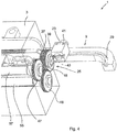
- a twisting unit 25 is arranged at a wire guide arc 5 opposite end of the region 27.
- the twisting unit 25 is adapted to receive and grasp the wire guided along the wire guide arc 5 and is further adapted to twist it by rotation about a rotation axis X.
- a drive chain 19 is arranged, which extends partially from the housing or base 3 of the device 1 out.
- the drive chain has a plurality of guide pins 21 which are adapted to stabilize and guide the drive chain 19 under shear load.
- the same reference numerals are given for similar or identical elements. With regard to the description of these elements, reference is therefore made to the other figures in each figure.
- the wire guide arc 5 is brought by lateral pivoting of the second side 11 of the wire guide arc in a position in which the opening 7 of the wire guide arc 5 is released.
- the opening allows embracing two or more adjacent, preferably crossing structural elements, for example two or more tension strands to twist them.
- Fig. 3 allows a view of the interior of the device 1.
- the wire to be twisted is fed in a plurality of supply channels 31a, 31b by means of a drive means 49 in the direction of the wire guide sheet 5.
- the drive means 49 has a piston 50, which deflects a first coupling member 52 and a second coupling member 53 in such a way that a clamping member 51, through which the wire is also passed, clamps it to the drive means 49.
- a promotion of the wire in the feed direction and counter to the feed direction is possible.
- the pulling carriage 23 is coupled to the drive chain 19.
- the movement of the drive chain 19 in both drive directions is ensured by means of a drive pinion 33, which is arranged drivable on the base body 3 of the device.
- a drive pinion 33 which is arranged drivable on the base body 3 of the device.
- the twisting unit 25 ( Figures 3 . 4 ) has two coaxial with each other and immediately adjacent gears 37, 39, through which in each case completely a first wire feedthrough hole 43 and a second wire feedthrough hole 45 extends completely therethrough.
- the first and second wire feedthrough hole 43, 45 are preferably arranged diametrically opposite to the axis of rotation of the two gears 37, 39 and adapted to receive the wire.
- the wire is passed through the first wire feedthrough hole 43 on the first side 9 of the wire guide sheet 5 by means of the drive means 49 and passed through the second wire feedthrough hole 45 by the pull slide 23 on the second side 11 of the wire guide sheet 5.
- a second clamping device 46 is adapted to clamp the wire, thereby shortening the loop by conveying the wire back through the drive means 49 when moving back from the second side 11 of the wire guide sheet 5 in the direction of the first Page 9 can be done.
- the drive and further details of the twisting unit 25 are also in Fig. 4 shown.
- the clamping device 41 of the pulling carriage 23 is preferably designed such that a first slide 36 for detecting and clamping the wire by the pulling carriage 23 deflects a second slide 38 when deflected from a release position, softer causes a jamming of the wire.
- the coupling of the first slider 36 with the second slider is preferably carried out by means of two matched slated planes, which allow sliding of the slides 36, 38 together and define the direction of movement of the slide.
- the first slider 36 is preferably arranged in such a way on the pull slide that it is moved towards a shoulder 40 when the pull slide 23 moves from the first side to the second side.
- the heel 40 and the slider 36 are first brought into contact with each other as the traction carriage 23 approaches its end position on the second side.
- Upon further approach of the traction slide 23 to its final position on the second side of the paragraph 40 presses against the slide and displaces it from its relative position on the Ceischlitten 23 in the direction of his (in FIG. 3 shown) release position.
- the first gear 37 of the twisting unit 25 is driven by means of a first gear 47.
- the second gear 39 of the twisting unit 25 is driven by means of a second gear 48.
- Gear 47 and 48 are connected by torsion shafts 55, 57 each having a servomotor.
- the first gear 37 and the second gear 39 are by means of the gears 47, 48 either opposite or can be driven in the same direction.
- the motors are preferably driven so that a co-driving of the gears 37, 38 takes place, such that the clamping of the wire is maintained.
- the wire feedthrough holes 43,45 are formed as elongated holes, wherein the elongated holes extend along curved paths.
- the cam tracks in the first gear 37 are not congruent with the cam tracks in the second gear 47.
- the curved paths are formed as circular arc sections, wherein the circular arc sections associated circle centers are arranged eccentrically with respect to the respective gear. This ensures that the clamping is made particularly gentle against each other in relative movement of the gears, since the slots formed as wire guide holes only gradually from their congruent position with each of the other gear associated portion of the wire feedthrough hole are brought.
- the gears 37,47 each have a plurality of holes sets of wire feedthrough holes. It is expected that over time, wear will occur at the hole edges due to the clamping force application. Gears with several sets of holes then have the advantage that no complete change is necessary, but only the "advancing" the gears to the next set of holes.
- Fig. 4 shown is a possible embodiment of a clamping device 41 within the traction slide 23. This is in accordance with Fig. 4 performed by a rotatable pin that can taper or close the passage for the supplied wire.
- the device 1 With reference to the FIGS. 1 to 4 below is a brief outline of the operation of the device 1 according to the invention.
- two or more structural elements such as tension strands
- the device 1 approximated to the twist area.
- the second side 11 of the wire guide arc 5 is opened by actuation of the lever kinematics 15 such that the opening 7 is released.
- the adjacent, preferably crossing, structural elements are introduced into the inner region 27 of the wire guide arc or are guided around it like a pair of tongs.
- the wire is fed in the direction of the draw slot 23 either manually or by means of a drive means such as the drive means 49.
- the wire is grasped by the pull slide 23 by means of a clamping device 41 and guided from the first side 9 of the wire guide bend 5 in the direction of the second side 11 of the wire guide bend.
- the pull slide 23 is already partially moved along the first side 9 of the wire guide arc 5 before the wire guide arc 5 has completely settled around the structural elements and the opening 7 is closed again.
- the pulling slide 23 is completely on the second side 11 of the wire guide bow method, where a transfer of the detected by the Switzerlandschlitten 23 wire to the second feedthrough opening 45 of the twisting unit 25 takes place. Even before feeding the wire, it has also been passed through the first wire guide opening 43 of the twisting unit 25.
- the wire forming a loop is clamped by means of a wire clamp 46.
- the pulling carriage 23 is released from the wire and moves partially or completely back to its original position on the first side of the wire guide sheet 5 (for example, according to FIG Fig. 1 ) back.
- the length of the formed wire loop is preferably shortened to a predetermined extent, which depends on the distance between the two wire lead-through openings 43, 45 and the required minimum loop length again according to the thickness of the structural elements.
- the shortening of the loop is preferably carried out by means of the drive means 49 or by re-detecting the wire by the pulling slide 23, if this is not yet completely in the position on the first side 9 of the wire guide arc 5 Fig. 1 ), and subsequent return transport by means of the pull slide.
- the gears 37, 39 are first driven in opposite directions by means of the gears 47, 48 and the motors connected to them, until a sufficient clamping within the twisting unit 25 is obtained.
- the gears 37, 39 are then driven in the same direction, and the wire is preferably separated within the device 1 by means of a cutting body, for example by means of one or more cutting edges on the gears.
- the twisting unit 25 performs a twisting movement about the axis X following the separation. After the desired number of revolutions, the opening 7 is released again and the device 1 is removed from the twisting area, for example to perform a next twisting operation.
Description
Die vorliegende Erfindung betrifft eine Vorrichtung zum automatischen Verdrillen von Metalldrähten, insbesondere zum Verbinden von benachbarten, vorzugsweise sich überkreuzenden Strukturelementen. Unter einem Strukturelement wird im Rahmen der Erfindung ein länglicher Körper verstanden, der einen runden oder polygonalen, beispielsweise viereckigen Querschnitt aufweist. Beispiele für solche Strukturelemente sind beispielsweise Rohre, Stäbe oder Träger, wie sie vielfach in allen Bereichen der Industrie verwendet werden. Auch unter den Begriff Strukturelement fallend werden Drahtseilbündel, sogenannte Litzen, oder Spannlitzen, angesehen, welche unter anderem zur Herstellung von Bewehrungskörben für Spannbetonbauelemente verwendet werden.The present invention relates to a device for automatically twisting metal wires, in particular for connecting adjacent, preferably crossing, structural elements. In the context of the invention, a structural element is understood to mean an elongate body which has a round or polygonal, for example quadrangular, cross section. Examples of such structural elements are, for example, tubes, rods or carriers, as they are widely used in all sectors of industry. Also covered by the term structural element are wire rope bundles, so-called strands, or prestressing strands, which are used inter alia for the production of reinforcing baskets for prestressed concrete elements.
Ein typisches Einsatzgebiet für Vorrichtungen der eingangs genannten Art ist die Herstellung von solchen Bewehrungskörben, bspw. für Spannbetonelemente. Bewehrungskörbe weisen eine gitterartige Struktur aus (Stahl-)Litzen auf. Die gitterartige Struktur wird erreicht, indem Litzen in einer ersten Richtung und Litzen in einer zweiten Richtung einander überkreuzend angeordnet werden. In dem Bereich, in welchem sie sich kreuzen, dem sogenannten Verdrillungsbereich, wird die Position der Litzen zueinander mittels eines Metalldrahts fixiert. Der Metalldraht wird um den Verdrillungsbereich der Litzen herumgelegt, wodurch eine Schlaufe gebildet wird. Die beiden Enden des Drahts werden sodann mehrfach gegeneinander verdrillt, bis die Schlaufe des Drahts hinreichend eng ist, um die beiden sich überkreuzenden Litzen bzw. allgemein die sich überkreuzenden Strukturelemente zueinander zu fixieren.A typical application for devices of the type mentioned is the production of such reinforcing cages, for example. For prestressed concrete elements. Reinforcing baskets have a latticed structure of (steel) strands. The lattice-like structure is achieved by interposing strands in a first direction and strands in a second direction crossing each other. In the area in which they intersect, the so-called twisting area, the position of the strands is fixed to each other by means of a metal wire. The metal wire is wrapped around the twist portion of the strands, forming a loop. The two ends of the Wires are then twisted against each other several times until the loop of the wire is sufficiently narrow to fix the two crossing strands or generally the intersecting structural elements to each other.
Alternativ zu einer überkreuzenden Anordnung mehrerer Strukturelemente werden auch häufig allgemein benachbarte Strukturelemente mittels Verdrillen von Drähten um die benachbarten Strukturelemente herum befestigt. Das Prozedere vollzieht sich mit Ausnahme der anderen Orientierung der Strukturelemente im Wesentlichen wie vorstehend beschrieben.As an alternative to a crossing arrangement of a plurality of structural elements, generally adjacent structural elements are often fastened by means of twisting wires around the adjacent structural elements. The procedure, with the exception of the other orientation of the structural elements, essentially takes place as described above.
Da beispielsweise Bewehrungskörbe aus einer Vielzahl von Litzen bestehen und demzufolge auch eine große Anzahl Verdrillungsbereiche vorhanden ist, müssen für die Herstellung eines Bewehrungskorbes sehr viele Drähte verdrillt werden. Bislang geschieht dies ausschließlich in manueller Arbeit. Da auch die für das Verdrillen zu verwendenden Drähte eine gewisse Stabilität aufweisen müssen, ist diese Tätigkeit kraftraubend für die entsprechend tätigen Personen und zudem sehr zeitaufwendig. Aufgrund des manuellen Charakters der Verdrillung kommt es auch zu ungleichmäßig verdrillten Drähten. Dies ist zwar aufgrund der Vielzahl der vorgenommenen Verdrillungen aus Sicht der Qualitätssicherung nicht schwerwiegend, allerdings wäre eine höhere Wiederholgenauigkeit beim Verdrillen von Drähten über benachbarten, vorzugsweise sich überkreuzenden Strukturelementen wünschenswert.For example, since reinforcing baskets consist of a plurality of strands and consequently a large number of twisting areas is present, many wires have to be twisted for the production of a reinforcing basket. So far, this is done exclusively in manual work. Since the wires to be used for twisting must also have a certain stability, this action is exhausting for the corresponding persons and also very time-consuming. Due to the manual nature of the twist, unevenly twisted wires also occur. Although this is not serious from the point of view of quality assurance due to the large number of twists made, a higher repeatability in twisting wires over adjacent, preferably crossing structural elements would be desirable.
Aus
Demzufolge lag der vorliegenden Erfindung die Aufgabe zugrunde, eine Vorrichtung und ein Verfahren anzugeben, welche die vorstehend beschriebenen Nachteile beheben.Accordingly, the present invention has the object to provide an apparatus and a method which overcome the disadvantages described above.
Die Erfindung löst die ihr zugrunde liegende Aufgabe bei einer Vorrichtung der eingangs genannten Art, indem diese gemäß den Merkmalen von Anspruch 1 ausgebildet ist. Die Erfindung löst die Aufgabe insbesondere, indem sie eine Vorrichtung zum automatischen Verdrillen von Metalldrähten, insbesondere zum Verbinden benachbarter, vorzugsweise sich überkreuzender Strukturelemente angibt, mit einer Drahtzuführung zum Zuführen von Draht, vorzugsweise Endlosdraht, in die Vorrichtung, einem Drahtführungsbogen, welcher eine selektiv freigeb- und verschließbare Öffnung aufweist und dazu eingerichtet ist, den zugeführten Draht in der geschlossenen Position entlang des Drahtführungsbogens von einer ersten Seite des Drahtführungsbogens zu einer bezogen auf die Öffnung gegenüberliegenden zweiten Seite des Drahtführungsbogens zu führen, einem Zugschlitten, welcher dazu eingerichtet ist, den zugeführten Draht auf der ersten Seite des Drahtführungsbogens zu erfassen und bei geschlossenem Drahtführungsbogen entlang des Drahtführungsbogens zu der zweiten Seite des Drahtführungsbogens hin zu ziehen, und einer Verdrilleinheit, die dazu eingerichtet ist, den zugeführten Draht auf beiden Seiten des Drahtführungsbogens zu erfassen und mittels einer Rotationsbewegung zu verdrillen.The invention solves the underlying object in a device of the type mentioned in that it is designed according to the features of
Vorteilhafte Ausgestaltungen und bevorzugte Ausführungsformen und Ausgestaltung der Erfindung ergeben sich aus den Unteransprüchen und der nachfolgenden Beschreibung.Advantageous embodiments and preferred embodiments and embodiment of the invention will become apparent from the dependent claims and the description below.
Die Erfindung macht sich insbesondere die Erkenntnis zunutze, dass eine Automatisierung des Verdrillens maßgeblich dazu beiträgt, ermüdungsfreier zu arbeiten, da insbesondere das Verdrillen kraftaufwendig ist.The invention makes use, in particular, of the finding that an automation of twisting contributes significantly to fatigue-free work, since in particular twisting is cumbersome.
Die Erfindung geht allerdings darüber hinaus noch weiter, indem sie eine Vorrichtung bereitstellt, die auch das Herumführen des Drahtes um den Verdrillungsbereich zweier oder mehrerer benachbarter, vorzugsweise sich überkreuzender Strukturelemente automatisiert ermöglicht, wodurch eine signifikante Beschleunigung des gesamten Arbeitsvorgangs erreicht wird. Das Zusammenspiel eines automatisierten Herumführens des Drahtes und des automatisierten Verdrillens beruht auf folgenden Leitgedanken: Der Draht wird entlang eines Drahtführungsbogens bewegt, um eine hohe Wiederholgenauigkeit hinsichtlich der Schlaufenbildung durch den Draht zu gewährleisten. Um den Drahtführungsbogen, der an der Vorrichtung ausgebildet ist, in den Verdrillungsbereich umschließender Weise anordnen zu können, ist eine Öffnung des Drahtführungsbogens vorgesehen. Dies erlaubt auch bei schwer zugänglichen Verdrillungsbereichen, wie sie beispielsweise bei Bewehrungskörben für Spannbetonbauelemente zu finden sind, ein einfaches Annähern der Vorrichtung an den Verdrillungsbereich, Umgreifen des Verdrillungsbereiches mit einem geöffneten Drahtführungsbogen und Umschließen des Verdrillungsbereiches durch Schließen der Öffnung. Die Betriebsweise ist beispielsweise ähnlich einer Zange. Weiterhin zeichnet sich die Erfindung darin aus, dass der Draht entlang des Drahtführungsbogens von dem Zugschlitten gezogen wird. Die erfindungsgemäße Ausgestaltung eines ziehenden Führens des Drahtes entlang des Drahtführungsbogens ist für weiche Drähte anwendbar, die ein besseres Verdrillen ermöglichen als Drähte aus hartem Material.. Die erfindungsgemäße Vorrichtung erlaubt es somit durch Öffnen und Schließen des Drahtführungsbogens, den Drahtführungsbogen um den Verdrillungsbereich zweier Strukturelemente zu legen, und der bewegbare Zugschlitten ermöglicht es sodann, den auf einer Seite des Drahtführungsbogens zugeführten Draht bei geschlossenem Drahtführungsbogen um den Verdrillungsbereich entlang des Drahtführungsbogens herumzuführen. Die Verdrilleinheit schließlich kann sodann den um den Verdrillungsbereich von dem Zugschlitten herumgeführten Draht auf beiden Seiten des Verdrillungsbereichs bzw. auf beiden Seiten des Drahtführungsbogens erfassen und, beispielsweise mittels eines rotatorischen Antriebs, das Verdrillen durchführen.However, the invention goes further still further by providing a device which also allows the wire to be passed around the twisting area of two or more adjacent, preferably intersecting structural elements, thereby achieving a significant acceleration of the overall operation. The interplay of automated wire-routing and automated twisting is based on the following guiding principles: The wire is moved along a wire guide arc to ensure a high repeat accuracy with regard to looping through the wire. In order to be able to arrange the wire guide arc, which is formed on the device in the twisting area enclosing manner, an opening of the wire guide arc is provided. This allows even in difficult to access Verdrillungsbereichen, as can be found, for example, reinforcement cages for prestressed concrete components, a simple approximation of the device to the Verdrillungsbereich, embracing the Verdrillungsbereiches with an open wire guide arc and enclosing the Verdrillungsbereiches by closing the opening. The operation is similar to a pair of pliers, for example. Furthermore, the invention is characterized in that the wire along the wire guide arc is pulled by the Zugschlitten. The inventive design of a pulling guide the wire along the wire guide arc is applicable to soft wires that allow better twisting than wires made of hard material .. The device of the invention thus allows by opening and closing the wire guide arc, the wire guide arc to the twisting region of two structural elements The movable pulling carriage then makes it possible to guide the wire fed on one side of the wire guide arc around the twisting area along the wire guide arc with the wire guide bow closed. Finally, the twisting unit can then handle the wire wound around the twisting area of the pulling carriage detect both sides of the twisting region or on both sides of the wire guide arc and, for example by means of a rotary drive, perform the twisting.
Vorzugsweise ist der Drahtführungsbogen zangenartig ausgebildet, und die selektiv freigeb- und verschließbare Öffnung ist proximal an der Vorrichtung angeordnet. Unter "proximal" wird hierbei - bezogen auf die Bedienausrichtung der Vorrichtung - das den zu verbindenden Strukturelementen zugewandte Ende der Vorrichtung verstanden.Preferably, the wire guide arc is tongs-like, and the selectively releasable and closable opening is proximal to the device. In this case, "proximal" is understood - with reference to the operating orientation of the device - to be the end of the device facing the structural elements to be connected.
Die Erfindung wird dadurch vorteilhaft weitergebildet, dass die Verdrilleinheit ein erstes Drahtdurchführungsloch und ein zweites Drahtdurchführungsloch aufweist, wobei die Drahtzuführung dazu eingerichtet ist, den zugeführten Draht durch das erste Drahtdurchführungsloch durchzuführen. Somit kann schon beim Zuführen des Drahtes in Richtung des Drahtführungsbogens das spätere Erfassen des Drahtes durch die Verdrilleinheit vorbereitet werden. Durch das Durchführen durch das Durchführungsloch ist der Draht bereits von der Verdrilleinheit erfassbar.The invention is advantageously further developed in that the twisting unit has a first wire feedthrough hole and a second wire feedthrough hole, wherein the wire feed is adapted to feed the supplied wire through the first wire feedthrough hole. Thus, even when feeding the wire in the direction of the wire guide arc, the later detection of the wire by the twisting unit can be prepared. By passing through the feedthrough hole, the wire is already detectable by the twisting unit.
Weiter vorzugsweise ist der Zugschlitten dazu eingerichtet, den zu der zweiten Seite des Drahtführungsbogens hingezogenen Draht derart durch das zweite Drahtdurchführungsloch durchzuführen, dass der Draht eine Schlaufe von dem ersten zu dem zweiten Durchführungsloch bildet. Vorteilhaft an dieser Ausführungsform ist insbesondere das Vorbereiten des Erfassens durch die Verdrilleinheit auf der zweiten Seite des Drahtführungsbogens in einem Arbeitsgang mittels des Zugschlittens beim Herumführen des Drahtes entlang des Drahtführungsbogens. Sobald die Schlaufe von dem Draht gebildet ist, wird dieser sogleich auch in das zweite Drahtdurchführungsloch der Verdrilleinheit ein- und dort hindurchgeführt.More preferably, the pulling carriage is configured to pass the wire drawn toward the second side of the wire guide arc through the second wire passing hole such that the wire forms a loop from the first to the second through hole. The advantage of this embodiment is in particular the preparation of the detection by the twisting unit on the second side of the wire guide arc in one operation by means of the pull slide in guiding the wire along the wire guide arc. As soon as the loop is formed by the wire, it is immediately inserted and guided into the second wire feed-through hole of the twisting unit.
In einer bevorzugten Ausführungsform weist die erfindungsgemäße Vorrichtung eine Klemmeinrichtung auf, die vorzugsweise auf der ersten oder zweiten Seite des Drahtführungsbogens angeordnet ist und die zum Festhalten des durch das erste Drahtdurchführungsloch durchgeführten Drahts eingerichtet ist oder zum Festhalten des durch das zweite Drahtdurchführungsloch durchgeführten Drahts eingerichtet ist. Insbesondere ist die Klemmeinrichtung dazu angepasst, den Draht nach dem Bilden der Schlaufe über den Verdrillungsbereich der beiden Strukturelemente hinweg zu fixieren, damit das Verdrillen durch die Verdrilleinheit weiter vorbereitet werden kann.In a preferred embodiment, the device according to the invention comprises a clamping device, which is preferably arranged on the first or second side of the wire guide arc and which is arranged for holding the wire passed through the first wire feedthrough hole or for holding the wire passed through the second wire feedthrough hole. In particular, the clamping device is adapted to fix the wire after forming the loop over the twisting region of the two structural elements, so that the twisting can be further prepared by the twisting unit.
Weiter vorzugsweise weist die erfindungsgemäße Vorrichtung ein Antriebsmittel zur Drahtförderung auf, wobei das Antriebsmittel dazu eingerichtet ist, den durch das zweite Drahtdurchführungsloch durchgeführten, von der Klemmeinrichtung festgehaltenen Draht zu fördern, um die gebildete Schlaufe auf ein vorbestimmtes Maß zu verkürzen. Beim Verdrillen des erfassten Drahtes mittels der Verdrilleinheit wird der Abstand zwischen der durch die Verdrillung erzeugten Einschnürung und den zu verdrillenden Strukturelementen mit jeder Umdrehung geringer. Um eine ausreichende Fixierung der Strukturelemente zu erreichen, ist eine gewisse Mindestanzahl von Verdrillungen erforderlich. Um auf der anderen Seite möglichst wenig Drahtverbrauch zu erreichen, soll die Anzahl der durchgeführten Verdrillungen ein maximales Maß nicht überschreiten. Deswegen wird es bevorzugt, den Abstand zwischen der Verdrilleinheit und den Strukturelementen durch Verkürzen der Drahtschlaufe vor dem Verdrillen zu limitieren und zu definieren. Als besonders bevorzugt hat sich herausgestellt, eine Schlaufenlänge einzustellen, die zwischen der Verdrilleinheit und den zu verbindenden Strukturelementen einen lichten Abstand übrig lässt, welcher dem Stichmaß zwischen dem ersten Drahtdurchführungsloch und dem zweiten Drahtdurchführungsloch entspricht.Further preferably, the device according to the invention comprises a drive means for wire conveying, wherein the drive means is adapted to promote the carried out by the second wire feedthrough hole, held by the clamping device wire to shorten the loop formed to a predetermined extent. When twisting the detected wire by means of the twisting unit, the distance between the constriction produced by the twist and the structural elements to be twisted decreases with each revolution. In order to achieve a sufficient fixation of the structural elements, a certain minimum number of twists is required. On the other hand, in order to achieve as little wire consumption as possible, the number of twists carried out should not exceed a maximum amount. Therefore, it is preferable to limit and define the distance between the twisting unit and the structural members by shortening the wire loop before twisting. It has been found to be particularly preferable to set a loop length which leaves a clearance between the twisting unit and the structural members to be connected which corresponds to the gauge between the first wire penetrating hole and the second wire penetrating hole.
Als Bezugspunkt für die Verdrilleinheit wird bei der Bestimmung des Abstandes diejenige Ebene angenommen, in welcher die Punkte liegen, an denen der Draht auf der ersten und zweiten Seite des Drahtführungsbogens von der Verdrilleinheit erfasst ist. Diese Ebene liegt vorzugsweise senkrecht zu der Rotationsachse der Verdrilleinheit.As a reference point for the twisting unit, in determining the distance, the plane in which the points at which the wire on the first and second sides of the wire guide arc is grasped by the twisting unit is assumed. This plane is preferably perpendicular to the axis of rotation of the twisting unit.
Es wird alternativ bevorzugt, das Antriebsmittel der Drahtzuführung zuzuordnen, wobei das Antriebsmittel dazu eingerichtet ist, den Draht wahlweise in Zuführungsrichtung oder entgegen der Zuführungsrichtung zu fördern. Die Förderungsrichtung wird in erster Linie davon abhängig gemacht, auf welcher der beiden Seiten des Drahtführungsbogens die Klemmeinrichtung angeordnet ist und den Draht festhält.It is alternatively preferred to assign the drive means of the wire feed, wherein the drive means is adapted to promote the wire either in the feed direction or counter to the feed direction. The conveying direction is primarily dependent on which of the two sides of the wire guide arc, the clamping device is arranged and holds the wire.
Gemäß einer weiteren bevorzugten Ausgestaltung weist das Antriebsmittel ein Antriebsglied auf, welches motorisch antreibbar ist und mit dem Zugschlitten derart gekoppelt ist, dass der Zugschlitten wahlweise von der ersten Seite des Drahtführungsbogens zu der zweiten Seite des Drahtführungsbogens hin und von der zweiten Seite des Drahtführungsbogens zu der ersten Seite des Drahtführungsbogens hin verfahrbar ist. Gemäß einer weiteren bevorzugten Ausführungsform weist die Verdrilleinheit zwei koaxial zueinander angeordnete Zahnräder auf, durch welche sich das erste und zweite Durchführungsloch jeweils vollständig hindurch erstrecken und wobei die beiden Zahnräder sowohl gegenläufig als auch gleichläufig antreibbar sind. Vorzugsweise sind die beiden koaxial angeordneten Zahnräder unmittelbar zueinander benachbart angeordnet. Ein gegenläufiges Antreiben der beiden Zahnräder bewirkt vorzugsweise ein Verklemmen des durch das erste und zweite Drahtdurchführungsloch durchgeführten Drahtes. Dies ermöglicht das Erfassen des Drahtes durch die Verdrilleinheit. Der Antrieb wird vorzugsweise mittels jeweils eines Servomotors realisiert.According to a further preferred embodiment, the drive means on a drive member which is driven by a motor and is coupled to the Zugschlitten such that the Zugschlitten selectively from the first side of the wire guide arc to the second side of the wire guide arc out and from the second side of the wire guide arc to the first side of the wire guide bow is movable. According to a further preferred embodiment, the twisting unit has two gear wheels arranged coaxially with one another through which the first and second feedthrough holes extend completely through each other and wherein the two gear wheels can be driven both in opposite directions and in the same direction. Preferably, the two coaxially arranged gears are arranged directly adjacent to each other. An opposite driving of the two gears preferably causes jamming of the wire passing through the first and second wire penetrating holes. This allows the detection of the wire by the twisting unit. The drive is preferably realized by means of a servo motor.
Sobald durch den gegenläufigen Antrieb der Zahnräder eine ausreichende Verklemmung des Drahtes erzielt worden ist, sind die beiden Zahnräder vorzugsweise gleichläufig antreibbar, und zwar derart, dass die Klemmung beibehalten wird, während die Zahnräder sich im Gleichlauf drehen, um die Verdrillung mittels einer Rotation der beiden Drahtdurchführungslöcher um eine gemeinsame Rotationsachse herbeizuführen.As soon as a sufficient clamping of the wire has been achieved by the counter drive of the gears, the two gears are preferably drivable in the same direction, in such a way that the clamping is maintained while the gears rotate in synchronism to the twist by means of a rotation of the two Wire feedthrough holes around a common axis of rotation bring about.
Weiter vorzugsweise weist die erfindungsgemäße Vorrichtung einen Schneidkörper auf, der zum Trennen des Drahts innerhalb der Vorrichtung angeordnet und dazu eingerichtet ist, den Draht auf der ersten Seite des Drahtführungsbogens und/oder auf der zweiten Seite des Drahtführungsbogens zu trennen. Hierdurch wird zusätzlich das Trennen des Drahts vor dem Verdrillen ermöglicht, ohne separate Schneidwerkzeuge bei sich führen zu müssen. Die erfindungsgemäße Vorrichtung erlaubt somit in einem einzigen, kontinuierlichen Arbeitsgang das Zuführen von Draht, Umlegen des Drahts um einen zu verdrillenden Verbund aus Strukturelementen, das Abtrennen des zur Verdrillung vorgesehenen Drahtabschnitts von einem zuführseitigen Drahtabschnitt und schließlich das Verdrillen des Drahtes.Further preferably, the device according to the invention comprises a cutting body, which is arranged for separating the wire within the device and adapted to separate the wire on the first side of the wire guide arc and / or on the second side of the wire guide arc. In this way, the separation of the wire is made possible before twisting, without having to carry separate cutting tools with him. The device according to the invention thus permits, in a single, continuous operation, the feeding of wire, wrapping of the wire around a composite of structural elements to be twisted, separation of the twisted wire section from a feed-side wire section, and finally twisting of the wire.
Der Schneidkörper ist vorzugsweise als scharfkantige Schneidkante innerhalb der Vorrichtung ausgebildet, welche benachbart zu dem durch die Vorrichtung hindurchgeführten Draht angeordnet ist. Vorzugsweise weisen eines oder beide der Zahnräder der Verdrilleinheit die Schneidkante(n) auf, welche derart an dem oder den Zahnrädern ausgebildet ist bzw. sind, dass das Abtrennen bei einsetzender Verdrillbewegung erfolgt.The cutting body is preferably formed as a sharp-edged cutting edge within the device, which is arranged adjacent to the wire passed through the device. Preferably, one or both of the gears of the twisting unit have the cutting edge (s) which is or are formed on the one or more gears such that the separation takes place when the twisting movement begins.
Die Erfindung betrifft weiterhin ein Verfahren zum automatischen Verdrillen eines Metalldrahts zum Verbinden zweier oder mehrerer benachbarter, vorzugsweise sich überkreuzender Strukturelemente. Die Erfindung löst die ihr zugrunde liegende, eingangs genannte Aufgabe bei einem solchen Verfahren mit den Schritten:
- Bereitstellen von zwei oder mehreren benachbarten, vorzugsweise sich überkreuzenden Strukturelementen,
- Zuführen des Drahtes in eine Vorrichtung nach einer der weiter oben beschriebenen bevorzugten Ausführungsformen,
- Durchführen eines Kreuzungsbereichs der Strukturelemente durch die freigegebene Öffnung des Drahtführungsbogens der Vorrichtung,
- Schließen der Öffnung des Drahtführungsbogens, so dass der Verdrillungsbereich der Strukturelemente von dem Drahtführungsbogen eingeschlossen ist,
- Erfassen des zugeführten Drahtes mittels des Zugschlittens
- Ziehen des zugeführten Drahtes mittels des Zugschlittens bei geschlossenem Drahtführungsbogen entlang des Drahtführungsbogens von der ersten Seite des Drahtführungsbogens zu der bezogen auf die Öffnung gegenüberliegenden zweiten Seite des Drahtführungsbogens,
- Erfassen des zugeführten Drahtes auf beiden Seiten des Drahtführungsbogens mittels der Verdrilleinheit, und
- Verdrillen des erfassten Drahtes mittels einer Rotationsbewegung der Verdrilleinheit.
- Providing two or more adjacent, preferably crossing, structural elements,
- Feeding the wire into a device according to one of the preferred embodiments described above,
- Passing a crossing region of the structural elements through the released opening of the wire guide arc of the device,
- Closing the opening of the wire guide arc so that the twist region of the structural elements is enclosed by the wire guide arc,
- Detecting the supplied wire by means of the Zugschlittens
- Pulling the supplied wire by means of the pulling carriage with the wire guide bow closed along the wire guide arc from the first side of the wire guide arc to the opposite side of the wire guide arc relative to the opening
- Detecting the supplied wire on both sides of the wire guide sheet by means of the twisting unit, and
- Twisting the detected wire by means of a rotational movement of the twisting unit.
Hinsichtlich der zugrunde liegenden Erkenntnisse und erfindungsgemäßen Vorteile wird auf das vorstehend mit Bezug auf die erfindungsgemäße Vorrichtung Gesagte verwiesen.With regard to the underlying findings and advantages according to the invention, reference is made to what has been said above with reference to the device according to the invention.
Das erfindungsgemäße Verfahren wird vorzugsweise weitergebildet, indem das Erfassen des zugeführten Drahts mittels einer Verdrilleinheit einen oder beide der Schritte umfasst:
- Durchführen des zugeführten Drahtes durch ein erstes Drahtdurchführungsloch der Verdrilleinheit, vorzugsweise mittels der Drahtzuführung der Vorrichtung,
- Durchführen des zu der zweiten Seite des Drahtführungsbogens hingezogenen Drahtes durch ein zweites Drahtdurchführungsloch der Verdrilleinheit derart, dass der Draht eine Schlaufe von dem ersten zu dem zweiten Drahtdurchführungsloch um die Strukturelemente herum bildet.
- Passing the supplied wire through a first wire feedthrough hole of the twisting unit, preferably by means of the wire feed of the device,
- Passing the wire drawn toward the second side of the wire guide arc through a second wire feedthrough hole of the twisting unit such that the wire forms a loop around the structural members from the first to the second wire feedthrough hole.
Weiter vorzugsweise umfasst das Verfahren den Schritt:
- Festhalten des durch das erste Drahtdurchführungsloch durchgeführten Drahtes oder des durch das zweite Drahtdurchführungsloch durchgeführten Drahtes mittels einer Klemmeinrichtung der Vorrichtung.
- Holding the wire passed through the first wire feed-through hole or the wire passed through the second wire feed-through hole by means of a clamping device of the device.
Gemäß einer bevorzugten Weiterbildung des Verfahrens umfasst dies ferner den Schritt:
- Fördern des durch das zweite Drahtdurchführungsloch durchgeführten, von der Klemmeinrichtung festgehaltenen Drahtes derart, dass die gebildete Schlaufe auf ein vorbestimmtes Maß zu verkürzt wird.
- Conveying the wire passed through the second wire feed-through hole and held by the clamper such that the loop formed is shortened to a predetermined extent.
Weiter vorzugsweise umfasst bei dem erfindungsgemäßen Verfahren der Schritt des Erfassens des zugeführten Drahtes auf beiden Seiten des Drahtführungsbogens mittels der Verdrilleinheit:
- ein gegenläufiges Antreiben von zwei koaxial angeordneten Zahnrädern, durch welche sich das erste und zweite Drahtdurchführungsloch jeweils vollständig hindurch erstrecken, derart, dass der durchgeführte Draht geklemmt wird, und
- ein gleichläufiges Antreiben der beiden Zahnräder mit geklemmtem Draht.
- oppositely driving two coaxially arranged gears through which the first and second wire penetrating holes respectively extend completely therethrough such that the passed wire is clamped, and
- a co-driving of the two gears with clamped wire.
Weiter vorzugsweise umfasst das erfindungsgemäße Verfahren den Schritt:
- Trennen des verdrillten Drahtes auf der ersten und/oder auf der zweiten Seite des Drahtführungsbogens mittels eines Schneidkörpers innerhalb der Vorrichtung.
- Separating the twisted wire on the first and / or on the second side of the wire guide arc by means of a cutting body within the device.
Die Erfindung betrifft ferner die Verwendung einer Vorrichtung gemäß einer der vorstehend beschriebenen bevorzugten Ausführungsformen zum automatischen Verdrillen von Metalldrähten, insbesondere zum Verbinden benachbarter, vorzugsweise sich überkreuzender Strukturelemente, zur Herstellung eines Bewehrungskorbes für ein Turmelement einer Windenergieanlage. Die Vorrichtung weist insbesondere auf:
eine Drahtzuführung zum Zuführen von Draht, vorzugsweise Endlosdraht, in die Vorrichtung, einen Drahtführungsbogen, welcher eine selektiv freigeb- und verschließbare Öffnung aufweist und dazu eingerichtet ist, den zugeführten Draht in der geschlossenen Position entlang des Drahtführungsbogens von einer ersten Seite des Drahtführungsbogens zu einer, bezogen auf die Öffnung gegenüberliegenden, zweiten Seite des Drahtführungsbogens zu führen, einen Zugschlitten, welcher dazu eingerichtet ist, den zugeführten Draht auf der ersten Seite des Drahtführungsbogens zu erfassen und zu der zweiten Seite des Drahtführungsbogens hin zu ziehen, und eine Verdrilleinheit, die dazu eingerichtet ist, den zugeführten Draht auf beiden Seiten des Drahtführungsbogens zu erfassen und mittels einer Rotationsbewegung zu verdrillen. Der Bewehrungskorb weist hierbei als erste und zweite Strukturelemente eine Vielzahl von ersten und zweiten Spannlitzen aufweist, welche einander überkreuzend angeordnet sind. Die Spannlitzen können optional miteinander verflochten sein, was die Positionierung der Spannlitzen vor dem Verdrillen des Drahtes erleichtert und die Stabilität des Korbes erhöht.The invention further relates to the use of a device according to one of the preferred embodiments described above for the automatic twisting of metal wires, in particular for connecting adjacent, preferably crossing structural elements, for producing a reinforcement cage for a tower element of a wind turbine. The device has in particular:
a wire feed for feeding wire, preferably endless wire, into the apparatus, a wire guide sheet having a selectively openable and closable opening and adapted to move the supplied wire in the closed position along the wire guide arc from a first side of the wire guide sheet to a wire guide arc; relative to the opening opposite the second side of the wire guide arc, a pulling carriage adapted to catch the supplied wire on the first side of the wire guide arc and pull it towards the second side of the wire guide arc, and a twisting unit adapted thereto is to detect the supplied wire on both sides of the wire guide arc and to twist by means of a rotary motion. In this case, the reinforcing cage has, as the first and second structural elements, a plurality of first and second prestressing strands which are arranged to cross one another. The tension strands can optionally be intertwined, which is the Positioning the tensioning strands before twisting the wire facilitates and increases the stability of the basket.
Die Vorteile der vorstehenden Weiterbildungen und bevorzugten Ausführungsformen der erfindungsgemäßen Vorrichtung gelten auch für die Weiterbildungen und bevorzugten Ausführungsformen des erfindungsgemäßen Verfahrens und die Weiterbildung der erfindungsgemäßen Verwendung.The advantages of the above developments and preferred embodiments of the device according to the invention also apply to the developments and preferred embodiments of the method according to the invention and the development of the use according to the invention.
Die Erfindung wird im Folgenden unter Bezugnahme auf die beigefügten Figuren und anhand eines Ausführungsbeispiels näher beschrieben. Hierbei zeigen:
-
Fig. 1 eine räumliche Ansicht einer erfindungsgemäßen Vorrichtung zum Verdrillen von Metalldrähten, -
Fig. 2 eine Seitenansicht der Vorrichtung gemäßFig. 1 in einem anderen Betriebszustand, -
Fig. 3 eine Seitenansicht der Vorrichtung gemäßFig. 1 in teilweiser Schnittdarstellung und -
Fig. 4 eine teilweise transparente räumliche Darstellung eines Ausschnitts der Vorrichtung gemäßFig. 1 .
-
Fig. 1 a spatial view of a device according to the invention for twisting metal wires, -
Fig. 2 a side view of the device according toFig. 1 in another operating state, -
Fig. 3 a side view of the device according toFig. 1 in partial sectional view and -
Fig. 4 a partially transparent spatial representation of a section of the device according toFig. 1 ,
In
In dem gezeigten Ausführungsbeispiel ist die erste Seite 9 des Drahtführungsbogens relativ zu dem Grundkörper 3 fix angeordnet, während die zweite Seite 11 des Drahtführungsbogens 5 mittels einer Hebelkinematik 15 derart auslenkbar ist, dass die Öffnung 7 aus der in
Der Drahtführungsbogen 5 ist im Wesentlichen zangenartig ausgebildet und weist im Inneren der beiden Seiten 9, 11 des Drahtführungsbogens einen Bereich 27 zur Aufnahme benachbarter, vorzugsweise sich überkreuzender Strukturelemente auf.The
Der Drahtführungsbogen 5 weist einen sich im Wesentlichen entlang des gesamten Bogens erstreckenden Schlitz 13 auf. Der Schlitz 13 unterteilt die erste Seite 9 des Drahtführungsbogens in zwei Teilbögen 9a, 9b. in analoger Weise unterteilt der Schlitz 13 die zweite Seite 11 des Drahtführungsbogens 5 in zwei Teilbögen 11a, 11b.The
Der Schlitz 13 ist dazu angepasst, einen Zugschlitten 23 aufzunehmen, welcher entlang des Drahtführungsbogens bewegbar und von einer innen in dem Drahtführungsbogen angeordneten Führungsnut 29 geführt ist.The
An einem dem Drahtführungsbogen 5 gegenüberliegenden Ende des Bereichs 27 ist eine Verdrilleinheit 25 angeordnet. Die Verdrilleinheit 25 ist zur Aufnahme und zum Erfassen des entlang des Drahtführungsbogens 5 geführten Drahtes angepasst und ferner dazu eingerichtet, diesen durch Rotation um eine Rotationsachse X zu verdrillen.At a
An einem dem Drahtführungsbogen 5 gegenüberliegenden, distalen Ende des Grundkörpers 3 ist eine Antriebskette 19 angeordnet, die sich teilweise aus dem Gehäuse bzw. Grundkörper 3 der Vorrichtung 1 heraus erstreckt. Die Antriebskette weist eine Vielzahl von Führungsstiften 21 auf, die zur Stabilisierung und Führung der Antriebskette 19 bei Schubbelastung eingerichtet sind.At a
In Bezug auf die weiteren Figuren werden für ähnliche oder identische Elemente die gleichen Bezugszeichen vergeben. Hinsichtlich der Beschreibung dieser Elemente wird deswegen bei jeder Figur auch auf die übrigen Figuren verwiesen. In dem in
In dem in
Der Zugschlitten 23 ist mit der Antriebskette 19 gekoppelt. Die Bewegung der Antriebskette 19 in beide Antriebsrichtungen wird mittels eines Antriebsritzels 33 gewährleistet, welches an dem Grundkörper 3 der Vorrichtung antreibbar angeordnet ist. Durch entsprechenden Antrieb der Antriebskette 19 wird der Zugschlitten 23 mittels der Nut 29 geführt und aus der in
Die Verdrilleinheit 25 (
Die Klemmeinrichtung 41 des Zugschlittens 23 ist vorzugsweise derart ausgestaltet, dass ein erster Schieber 36 zum Erfassen und Klemmen des Drahtes durch den Zugschlitten 23 bei Auslenkung aus einer Freigabeposition einen zweiten Schieber 38 auslenkt, weicher eine Verklemmung des Drahtes verursacht. Die Kopplung des ersten Schiebers 36 mit dem zweiten Schieber erfolgt vorzugsweise mittels zweier aneinandergepasster schiefer Ebenen, die ein Abgleiten der Schieber 36, 38 aneinander ermöglichen und die Bewegungsrichtung der Schieber definieren.The clamping
Der erste Schieber 36 ist vorzugsweise derart an dem Zugschlitten angeordnet uns ausgerichtet, dass er bei Bewegung des Zugschlittens 23 von der ersten Seite zu der zweiten Seite hin auf einen Absatz 40 zu bewegt wird. Der Absatz 40 und der Schieber 36 werden beim Annähern des Zugschlittens 23 an seine Endposition auf der zweiten Seite zunächst miteinander in Kontakt gebracht. Bei weiterer Annäherung des Zugschlittens 23 an seine Endposition auf der zweiten Seite drückt der Absatz 40 gegen den Schieber und verdrängt diesen aus seiner Relativposition an dem Zugschlitten 23 in Richtung seiner (in
Vorzugsweise sind die Drahtdurchführungslöcher 43,45 als Langlöcher ausgebildet, wobei die Langlöcher entlang von Kurvenbahnen verlaufen. Vorzugsweise sind die Kurvenbahnen in dem ersten Zahnrad 37 nicht deckungsgleich zu den Kurvenbahnen in dem zweiten Zahnrad 47. Besonders bevorzugt sind die Kurvenbahnen als Kreisbogenabschnitte ausgebildet, wobei die den Kreisbogenabschnitten zugehörigen Kreismittelpunkte exzentrisch im Bezug auf das jeweilige Zahnrad angeordnet sind. Hierdurch wird erreicht, dass die Klemmung bei Relativbewegung der Zahnräder gegeneinander besonders sanft aufgebaut wird, da die als Langlöcher ausgebildeten Drahtführunglöcher nur allmählich aus ihrer deckungsgleichen Lage mit dem jeweils dem anderen Zahnrad zugeordneten Abschnitt des Drahtdurchführungslochs gebracht werden.Preferably, the wire feedthrough holes 43,45 are formed as elongated holes, wherein the elongated holes extend along curved paths. Preferably, the cam tracks in the
Gemäß einer bevorzugten Ausführungsform weisen die Zahnräder 37,47 jeweils mehrere Lochsätze von Drahtdurchführungslöchern auf. Es ist davon auszugehen, dass im Laufe der Zeit Verschleiß an den Lochkanten infolge der Klemmkraftbeaufschlagung auftritt. Zahnräder mit mehreren Lochsätzen haben dann den Vorteil, dass kein kompletter Wechsel notwendig ist, sondern nur das "Weiterstellen" der Zahnräder auf den nächsten Lochsatz.According to a preferred embodiment, the
Ebenfalls in
Unter Bezugnahme auf die
In Vorbereitung einer Schlaufenbildung wird der Draht in Richtung des Zugschlitzes 23 entweder manuell oder mittels eines Antriebsmittels, wie beispielsweise dem Antriebsmittel 49, zugeführt. Der Draht wird von dem Zugschlitten 23 mittels einer Klemmeinrichtung 41 erfasst und von der ersten Seite 9 des Drahtführungsbogens 5 in Richtung der zweiten Seite 11 des Drahtführungsbogens geführt. Optional wird der Zugschlitten 23 bereits partiell entlang der ersten Seite 9 des Drahtführungsbogens 5 verfahren, bevor sich der Drahtführungsbogen 5 vollständig um die Strukturelemente gelegt hat und die Öffnung 7 wieder verschlossen ist. Bei verschlossener Öffnung 7 wird der Zugschlitten 23 vollständig auf die zweite Seite 11 des Drahtführungsbogens verfahren, wo eine Übergabe des von dem Zugschlitten 23 erfassten Drahtes an die zweite Durchführungsöffnung 45 der Verdrilleinheit 25 erfolgt. Bereits zuvor beim Zuführen des Drahtes ist dieser auch durch die erste Drahtführungsöffnung 43 der Verdrilleinheit 25 durchgeführt worden.In preparation for looping, the wire is fed in the direction of the
Im Anschluss wird der Draht, der eine Schlaufe bildet, mittels einer Drahtklemme 46 festgeklemmt. Der Zugschlitten 23 wird vom Draht gelöst und fährt teilweise oder vollständig wieder in seine ursprüngliche Position auf der ersten Seite des Drahtführungsbogens 5 (beispielsweise gemäß
Bevor die Verdrilleinheit 25 das Verdrillen des Drahtes durch Rotation der beiden Drahtdurchführungsöffnungen 43, 45 umeinander ausführt, wird vorzugsweise die Länge der gebildeten Drahtschlaufe auf ein vorbestimmtes Maß verkürzt, welches abhängig ist vom Abstand der beiden Drahtdurchführungsöffnungen 43, 45 sowie der benötigten Mindestschlaufenlänge, die sich wiederum nach der Dicke der Strukturelemente richtet.Before the twisting
Die Verkürzung der Schlaufe erfolgt vorzugsweise mittels des Antriebsmittels 49 oder mittels erneuten Erfassens des Drahtes durch den Zugschlitten 23, wenn dieser noch nicht vollständig in die Position auf der ersten Seite 9 des Drahtführungsbogens 5 (
Wenn die Schlaufe die vorbestimmte Länge erreicht hat, werden die Zahnräder 37, 39 zunächst gegenläufig mittels der Zahnräder 47, 48 und der mit ihnen verbundenen Motoren angetrieben, bis eine ausreichende Verklemmung innerhalb der Verdrilleinheit 25 erlangt ist. In diesem verklemmten Zustand werden die Zahnräder 37, 39 sodann gleichläufig angetrieben, und der Draht wird innerhalb der Vorrichtung 1 vorzugsweise mittels eines Schneidkörpers, beispielsweise mittels einer oder mehrerer Schneidkanten an den Zahnrädern, getrennt. die Verdrilleinheit 25 führt im Anschluss an das Trennen eine Verdrillbewegung um die Achse X aus. Nach der gewünschten Anzahl Umdrehungen wird die Öffnung 7 erneut freigegeben und die Vorrichtung 1 von dem Verdrillungsbereich entfernt, um beispielsweise eine nächste Verdrilloperation durchzuführen.When the loop has reached the predetermined length, the
Wie sich aus den vorstehenden Beschreibungen ergibt, erfolgt der gesamte Vorgang des Schlaufenbildens und Verdrillens automatisiert, was eine signifikante Arbeitserleichterung für Bediener darstellt.As can be seen from the above descriptions, the whole process of looping and twisting is automated, which is a significant labor hassle for operators.
Claims (17)
- An apparatus (1) for automatically twisting metal wires, in particular for connecting adjacent, preferably mutually crossing structural elements, comprisinga wire feed means for feeding wire, preferably endless wire, into the apparatus,an arcuate wire guide (5) which has a selectively openable and closable opening (7) and which is adapted to guide the fed wire in the closed position along the arcuate wire guide from a first side (9) of the arcuate wire guide to a second side (11) of the arcuate wire guide, that is in opposite relationship with respect to the opening, anda twisting unit (25) adapted to engage the fed wire on both sides of the arcuate wire guide and to twist it by means of a rotational movement
characterized by a pulling slider (23) adapted to engage the fed wire on the first side (9) of the arcuate wire guide and to pull it, when the arcuate wire guide is closed, towards the second side of the arcuate wire guide along the arcuate wire guide. - An apparatus according to claim 1 wherein the arcuate wire guide (5) is of a tongs-like configuration and the selectively openable and closable opening (7) is arranged proximally on the apparatus (1).
- An apparatus according to claim 1 or claim 2 wherein the twisting unit (25) has a first wire guide passage hole (43) and a second wire guide passage hole (45) and wherein the wire feed means is adapted to pass the fed wire through the first wire guide passage hole.
- An apparatus according to claim 3 wherein the pulling slider (23) is adapted to pass the wire pulled to the second side (11) of the arcuate wire guide through the second wire guide passage hole (45) in such a way that the wire forms a loop from the first to the second wire guide passage hole.
- An apparatus according to claim 3 or claim 4 comprising a clamping device (41, 46) which is preferably arranged on the first or the second side of the arcuate wire guide and which is adapted to hold fast the wire passed through the first wire guide passage hole or is adapted to hold fast the wire passed through the second wire guide passage hole.
- An apparatus according to claim 5 comprising a drive means (31, 49) for wire conveyance, wherein the drive means is adapted to convey the wire passed through the second wire guide passage hole (45) and held fast by the clamping device (46) to shorten the formed loop to a predetermined size.
- An apparatus according to claim 6 wherein the drive means (49) is associated with the wire feed means and is adapted to convey the wire selectively in the feed direction or in opposite relationship to the feed direction.
- An apparatus according to claim 6 wherein the drive means (33) has a drive member which is motor-drivable and is coupled to the pulling slider in such a way that the pulling slider is displaceable selectively from the first side of the arcuate wire guide towards the second side of the arcuate wire guide and from the second side of the arcuate wire guide towards the first side of the arcuate wire guide.
- An apparatus according to one of claims 3 to 8 wherein the twisting unit has two coaxially arranged gears (37, 39) through which the first and second wire guide passage holes respectively completely extend and wherein the two gears are drivable both in opposite directions and also in the same direction.
- An apparatus according to one of the preceding claims comprising a cutting body which is arranged to sever the wire within the apparatus and is adapted to sever the wire on the first side of the arcuate wire guide and/or on the second side of the arcuate wire guide.
- A method of automatically twisting a metal wire for connecting two or more adjacent, preferably mutually crossing structural elements, comprising the steps:- providing two adjacent, preferably mutually crossing structural elements,- feeding the wire into an apparatus according to one of claims 1 to 10,- passing a crossing region of the structural elements through the opened opening of the arcuate wire guide of the apparatus,- closing the opening of the arcuate wire guide so that the crossing region of the structural elements is enclosed by the arcuate wire guide,- engaging the fed wire by means of the pulling slider,- pulling the fed wire by means of the pulling slider, with the arcuate wire guide closed, along the arcuate wire guide from the first side of the arcuate wire guide to the second side of the arcuate wire guide, that is in opposite relationship with respect to the opening,- engaging the fed wire on both sides of the arcuate wire guide by means of the twisting unit, and- twisting the engaged wire by means of a rotational movement of the twisting unit.
- A method according to claim 11 wherein the step of engaging the fed wire by means of the twisting unit includes one or both of the steps:- passing the fed wire through a first wire guide passage hole of the twisting unit, preferably by means of the wire feed means of the apparatus, and- passing the wire which has been pulled to the second side of the arcuate wire guide trough a second wire guide passage hole of the twisting unit in such a way that the wire forms a loop from the first to the second wire guide passage hole around the structural elements.
- A method according to claim 12 including:- holding fast the wire passed through the first wire guide passage hole or the wire passed through the second wire guide passage hole by means of a clamping device of the apparatus.
- A method according to claim 13 including:- conveying the wire passed through the second wire guide passage hole and held fast by the clamping device in such a way that the formed loop is reduced to a predetermined size.
- A method according to one of claims 11 to 14 wherein the step of engaging the fed wire on both sides of the arcuate wire guide by means of the twisting unit includes:- driving in opposite directions two coaxially arranged gears, through which the first and second wire guide passage holes respectively completely extend, in such a way that the wire passed therethrough is clamped, andwherein the step of twisting the engaged wire by means of rotational movement of the twisting unit includes:- driving in the same direction the two gears with the clamped wire.
- A method according to one of claims 11 to 15 including the step:- severing the wire on the first and/or on the second side of the arcuate wire guide by means of a cutting body within the apparatus prior to the twisting step.
- Use of an apparatus (1) for automatically twisting metal wires, in particular for connecting adjacent, preferably mutually crossing structural elements, for the production of a reinforcing cage for a pylon element of a wind power installation, wherein the apparatus is designed in accordance of one of claims 1 to 10, wherein
the reinforcing cage as first structural elements has a plurality of first and second prestressing cables arranged in mutually crossing relationship.
Applications Claiming Priority (2)
| Application Number | Priority Date | Filing Date | Title |
|---|---|---|---|
| DE102012216831.1A DE102012216831A1 (en) | 2012-09-19 | 2012-09-19 | Device and method for automatic twisting of metal wires, in particular for connecting adjacent, preferably crossing structural elements |
| PCT/EP2013/065678 WO2014044443A1 (en) | 2012-09-19 | 2013-07-25 | Device and method for automatically twisting metal wires, in particular for connecting adjacent, preferably mutually intersecting structure elements |
Publications (2)
| Publication Number | Publication Date |
|---|---|
| EP2897744A1 EP2897744A1 (en) | 2015-07-29 |
| EP2897744B1 true EP2897744B1 (en) | 2018-09-12 |
Family
ID=48875049
Family Applications (1)
| Application Number | Title | Priority Date | Filing Date |
|---|---|---|---|
| EP13741751.5A Active EP2897744B1 (en) | 2012-09-19 | 2013-07-25 | Device and method for automatically twisting metal wires, in particular for connecting adjacent, preferably mutually intersecting structure elements |
Country Status (21)
| Country | Link |
|---|---|
| US (1) | US9808854B2 (en) |
| EP (1) | EP2897744B1 (en) |
| JP (1) | JP6242901B2 (en) |
| KR (1) | KR101727418B1 (en) |
| CN (1) | CN104640647B (en) |
| AR (1) | AR092606A1 (en) |
| AU (1) | AU2013320549B2 (en) |
| BR (1) | BR112015005938A2 (en) |
| CA (1) | CA2881754C (en) |
| CL (1) | CL2015000677A1 (en) |
| DE (1) | DE102012216831A1 (en) |
| DK (1) | DK2897744T3 (en) |
| ES (1) | ES2693346T3 (en) |
| IN (1) | IN2015DN01226A (en) |
| MX (1) | MX353873B (en) |
| NZ (1) | NZ705009A (en) |
| PT (1) | PT2897744T (en) |
| RU (1) | RU2600779C1 (en) |
| TW (1) | TWI566853B (en) |
| WO (1) | WO2014044443A1 (en) |
| ZA (1) | ZA201500906B (en) |
Families Citing this family (11)
| Publication number | Priority date | Publication date | Assignee | Title |
|---|---|---|---|---|
| DE102013225049A1 (en) | 2013-12-05 | 2015-06-11 | Wobben Properties Gmbh | Plant for the production of reinforcement baskets for tower segments of wind turbines |
| DK3326921T3 (en) | 2015-07-22 | 2022-08-15 | Max Co Ltd | Binding machine |
| JP6737274B2 (en) | 2015-07-22 | 2020-08-05 | マックス株式会社 | Binding machine |
| ES2856950T3 (en) | 2015-07-22 | 2021-09-28 | Max Co Ltd | Tying machine |
| DE102016205048B3 (en) * | 2016-03-24 | 2017-07-13 | Wafios Aktiengesellschaft | Clamping head unit for wire bending machine |
| JP6887760B2 (en) * | 2016-05-20 | 2021-06-16 | 株式会社マキタ | Reinforcing bar binding machine |
| EP3410547B1 (en) * | 2017-05-31 | 2021-05-05 | Komax Holding Ag | Method and device for processing a cable |
| SE541178C2 (en) * | 2017-09-08 | 2019-04-23 | Skanska Sverige Ab | A tool, a system and a method for manufacturing of a reinforcement bar structure |
| JP7427994B2 (en) | 2020-02-10 | 2024-02-06 | マックス株式会社 | Binding machine |
| EP3862511A1 (en) | 2020-02-10 | 2021-08-11 | Max Co., Ltd. | Binding machine |
| RU2739484C1 (en) * | 2020-06-30 | 2020-12-24 | Роман Валерьевич Шестаков | Device for twisting of binding wire |
Citations (1)
| Publication number | Priority date | Publication date | Assignee | Title |
|---|---|---|---|---|
| JPH0699926A (en) * | 1992-09-14 | 1994-04-12 | Yoshiaki Tange | Tying machine |
Family Cites Families (27)
| Publication number | Priority date | Publication date | Assignee | Title |
|---|---|---|---|---|
| DE1066486B (en) * | 1960-03-03 | Societc H. Brenneisen έχ Cic, Paris | Twisting device | |
| DE1677205U (en) * | 1952-01-02 | 1954-06-03 | Albert Hudzik | AUXILIARY DEVICE FOR TWISTING OF BINDING WIRES, IN PARTICULAR FOR CONNECTING REINFORCEMENT IRON. |
| DE1280197B (en) * | 1966-04-05 | 1968-10-17 | Boelkow Gmbh | Device for twisting wires |
| DE1752554A1 (en) | 1968-06-14 | 1971-05-19 | Thompson Tools Inc | Device for twisting the ends of wire loops |
| AT349861B (en) | 1976-05-25 | 1979-04-25 | Evg Entwicklung Verwert Ges | BINDING TOOL FOR TWISTING THE FREE ENDS OF A BINDING WIRE AND LATTICE TYING MACHINE WITH SUCH TOOLS |
| SU990386A1 (en) | 1980-06-03 | 1983-01-23 | Центральное Экспериментальное Конструкторское Бюро Комплексной Механизации И Автоматизации В Строительстве | Apparatus for bending reinforcement rods with wire |
| US4362192A (en) * | 1981-03-05 | 1982-12-07 | Furlong Donn B | Wire tying power tool |
| FR2502582A1 (en) | 1981-03-26 | 1982-10-01 | Grenon Rene | TWISTING SYSTEM FOR METALLIC WIRES |
| JPS61191764A (en) | 1985-02-18 | 1986-08-26 | 湯口 貞雄 | Apparatus for bundling iron bars |
| US4842025A (en) * | 1986-01-17 | 1989-06-27 | Milbar Corporation | Wire twisting tool |
| JPS62270238A (en) | 1986-05-17 | 1987-11-24 | Toyota Kihan:Kk | Reinforcing bar binding machine |
| US4829753A (en) * | 1988-01-15 | 1989-05-16 | Bricmont Francis H | Apparatus for wrapping overlapping laps of strip material over a cylindrical object having an axial opening therein |
| SE9003176D0 (en) * | 1990-10-04 | 1990-10-04 | Peter Hoyaukin | SEAT AND MACHINE CONNECTING CROSSING RODS |
| US5217049A (en) | 1991-08-02 | 1993-06-08 | Gateway Construction Company, Inc. | Power rebar typing tool |
| MY130074A (en) | 1992-02-28 | 2007-05-31 | Bentac Co Ltd | Method and apparatus for tying one more articles |
| US5431196A (en) * | 1994-01-03 | 1995-07-11 | Belcan Specialty Equipment Engineering Division Of Belcan Engineering Groups, Inc. | Power rebar tying tool |
| CA2192568A1 (en) | 1994-06-24 | 1996-01-04 | Graeme John Doyle | Wire tying tool with drive mechanism |
| WO1996000135A1 (en) | 1994-06-24 | 1996-01-04 | Talon Industries, Llc | Wire tying tool with drive mechanism |
| US5657799A (en) | 1994-10-17 | 1997-08-19 | Max Co., Ltd. | Safety device in reinforcing bars binding machine |
| DE20219323U1 (en) * | 2002-12-12 | 2003-03-06 | Wille Gmbh & Co Kg Eduard | Clamping device for wire whirling pliers |
| KR100436446B1 (en) | 2003-08-29 | 2004-06-30 | 주식회사 하나 | An auto-binding apparatus for reinforcing |
| EP1951973B1 (en) | 2005-10-10 | 2014-12-10 | Tymatic Ltd. | Apparatus for binding objects together |
| RU2429100C2 (en) | 2005-10-10 | 2011-09-20 | Таймэтик Лтд | Device for items binding |
| JP5045548B2 (en) | 2008-05-19 | 2012-10-10 | マックス株式会社 | Rebar binding machine |
| CN201232363Y (en) | 2008-07-17 | 2009-05-06 | 易笑婕 | Electric steel binding machine |
| RU90097U1 (en) | 2009-08-05 | 2009-12-27 | Анатолий Павлович Цапиев | DEVICE FOR KNITTING REINFORCED RODS |
| US8622440B2 (en) * | 2010-10-05 | 2014-01-07 | Ideal Industries, Inc. | Knot tying device and cartridge system for providing tying filament thereto |
-
2012
- 2012-09-19 DE DE102012216831.1A patent/DE102012216831A1/en not_active Ceased
-
2013
- 2013-07-25 DK DK13741751.5T patent/DK2897744T3/en active
- 2013-07-25 MX MX2015002768A patent/MX353873B/en active IP Right Grant
- 2013-07-25 NZ NZ705009A patent/NZ705009A/en not_active IP Right Cessation
- 2013-07-25 ES ES13741751.5T patent/ES2693346T3/en active Active
- 2013-07-25 US US14/428,934 patent/US9808854B2/en not_active Expired - Fee Related
- 2013-07-25 WO PCT/EP2013/065678 patent/WO2014044443A1/en active Application Filing
- 2013-07-25 BR BR112015005938A patent/BR112015005938A2/en not_active Application Discontinuation
- 2013-07-25 KR KR1020157009946A patent/KR101727418B1/en active IP Right Grant
- 2013-07-25 CA CA2881754A patent/CA2881754C/en not_active Expired - Fee Related
- 2013-07-25 AU AU2013320549A patent/AU2013320549B2/en not_active Ceased
- 2013-07-25 JP JP2015532339A patent/JP6242901B2/en not_active Expired - Fee Related
- 2013-07-25 RU RU2015114524/02A patent/RU2600779C1/en not_active IP Right Cessation
- 2013-07-25 CN CN201380048840.9A patent/CN104640647B/en not_active Expired - Fee Related
- 2013-07-25 PT PT13741751T patent/PT2897744T/en unknown
- 2013-07-25 EP EP13741751.5A patent/EP2897744B1/en active Active
- 2013-08-14 TW TW102129181A patent/TWI566853B/en not_active IP Right Cessation
- 2013-09-18 AR ARP130103339A patent/AR092606A1/en active IP Right Grant
-
2015
- 2015-02-09 ZA ZA2015/00906A patent/ZA201500906B/en unknown
- 2015-02-16 IN IN1226DEN2015 patent/IN2015DN01226A/en unknown
- 2015-03-18 CL CL2015000677A patent/CL2015000677A1/en unknown
Patent Citations (1)
| Publication number | Priority date | Publication date | Assignee | Title |
|---|---|---|---|---|
| JPH0699926A (en) * | 1992-09-14 | 1994-04-12 | Yoshiaki Tange | Tying machine |
Also Published As
| Publication number | Publication date |
|---|---|
| BR112015005938A2 (en) | 2017-07-04 |
| KR20150059764A (en) | 2015-06-02 |
| CA2881754A1 (en) | 2014-03-27 |
| WO2014044443A1 (en) | 2014-03-27 |
| AR092606A1 (en) | 2015-04-29 |
| RU2600779C1 (en) | 2016-10-27 |
| MX2015002768A (en) | 2015-08-14 |
| TW201412428A (en) | 2014-04-01 |
| MX353873B (en) | 2018-02-01 |
| PT2897744T (en) | 2018-12-19 |
| AU2013320549A1 (en) | 2015-03-05 |
| TWI566853B (en) | 2017-01-21 |
| DK2897744T3 (en) | 2018-12-03 |
| CA2881754C (en) | 2017-01-24 |
| DE102012216831A1 (en) | 2014-03-20 |
| KR101727418B1 (en) | 2017-04-14 |
| NZ705009A (en) | 2016-02-26 |
| JP6242901B2 (en) | 2017-12-06 |
| IN2015DN01226A (en) | 2015-06-26 |
| CL2015000677A1 (en) | 2015-07-10 |
| EP2897744A1 (en) | 2015-07-29 |
| CN104640647A (en) | 2015-05-20 |
| ES2693346T3 (en) | 2018-12-11 |
| JP2015534509A (en) | 2015-12-03 |
| US20150266082A1 (en) | 2015-09-24 |
| AU2013320549B2 (en) | 2015-12-03 |
| US9808854B2 (en) | 2017-11-07 |
| ZA201500906B (en) | 2015-12-23 |
| CN104640647B (en) | 2017-07-21 |
Similar Documents
| Publication | Publication Date | Title |
|---|---|---|
| EP2897744B1 (en) | Device and method for automatically twisting metal wires, in particular for connecting adjacent, preferably mutually intersecting structure elements | |
| DE2720027C3 (en) | Tying tool for twisting the free ends of a binding wire | |
| EP3182421A1 (en) | Twisting of single lines | |
| DE19630023B4 (en) | Device for deforming rod-shaped components | |
| EP1969945B1 (en) | Method and device for controlled closing of at least one clip around a braided section devoid of filling material between two filling material sections in a wrapper | |
| DE3928196C2 (en) | ||
| DE2723846A1 (en) | BENDING MACHINE FOR WIRE | |
| DE2420690A1 (en) | DEVICE FOR BENDING TUBE SECTIONS | |
| EP2428452B1 (en) | Method and strapping device for applying flat straps around packages | |
| DE202010001324U1 (en) | Device for twisting lines | |
| DE3909093A1 (en) | METHOD AND DEVICE FOR PROCESSING CABLE MATERIAL | |
| EP2789406B2 (en) | Bending machine | |
| DE3809496C2 (en) | Ring winding device | |
| EP0144404B1 (en) | Method for connecting two bars which are crossing each other and device for implementing such method | |
| DE2843531C2 (en) | Machine for the production of lattice girder-like reinforcement structures for reinforced concrete | |
| EP3456443B1 (en) | Material bar supply device | |
| EP3448202B1 (en) | Device for producing round brushes | |
| DE4412203A1 (en) | Method and apparatus for the production of semi-finished parts from wire | |
| DE10212993A1 (en) | Electrical cable shoe crimping method has cable filaments held together by insulation ring during crimping procedure | |
| DE3728974A1 (en) | DEVICE FOR AUTOMATICALLY TAPING COILS | |
| DE3307214A1 (en) | Method for connecting two mutually crossing bars, and a device for carrying out the method | |
| CH592481A5 (en) | Fixture for bending concrete reinforcement bars - has anvil and bending mandrel and crops bar after last bend | |
| DE3741215C2 (en) | ||
| DE202021106333U1 (en) | Automatic core winding machine | |
| DE48896C (en) | Method and machine for tying bottle corks |
Legal Events
| Date | Code | Title | Description |
|---|---|---|---|
| PUAI | Public reference made under article 153(3) epc to a published international application that has entered the european phase |
Free format text: ORIGINAL CODE: 0009012 |
|
| 17P | Request for examination filed |
Effective date: 20150420 |
|
| AK | Designated contracting states |
Kind code of ref document: A1 Designated state(s): AL AT BE BG CH CY CZ DE DK EE ES FI FR GB GR HR HU IE IS IT LI LT LU LV MC MK MT NL NO PL PT RO RS SE SI SK SM TR |
|
| AX | Request for extension of the european patent |
Extension state: BA ME |
|
| RAP1 | Party data changed (applicant data changed or rights of an application transferred) |
Owner name: WOBBEN PROPERTIES GMBH |
|
| GRAP | Despatch of communication of intention to grant a patent |
Free format text: ORIGINAL CODE: EPIDOSNIGR1 |
|
| STAA | Information on the status of an ep patent application or granted ep patent |
Free format text: STATUS: GRANT OF PATENT IS INTENDED |
|
| INTG | Intention to grant announced |
Effective date: 20180405 |
|
| GRAS | Grant fee paid |
Free format text: ORIGINAL CODE: EPIDOSNIGR3 |
|
| GRAA | (expected) grant |
Free format text: ORIGINAL CODE: 0009210 |
|
| STAA | Information on the status of an ep patent application or granted ep patent |
Free format text: STATUS: THE PATENT HAS BEEN GRANTED |
|
| AK | Designated contracting states |
Kind code of ref document: B1 Designated state(s): AL AT BE BG CH CY CZ DE DK EE ES FI FR GB GR HR HU IE IS IT LI LT LU LV MC MK MT NL NO PL PT RO RS SE SI SK SM TR |
|
| AX | Request for extension of the european patent |
Extension state: BA ME |
|
| REG | Reference to a national code |
Ref country code: GB Ref legal event code: FG4D Free format text: NOT ENGLISH |
|
| REG | Reference to a national code |
Ref country code: CH Ref legal event code: EP |
|
| REG | Reference to a national code |
Ref country code: IE Ref legal event code: FG4D Free format text: LANGUAGE OF EP DOCUMENT: GERMAN |
|
| REG | Reference to a national code |
Ref country code: DE Ref legal event code: R096 Ref document number: 502013011072 Country of ref document: DE |
|
| REG | Reference to a national code |
Ref country code: AT Ref legal event code: REF Ref document number: 1039935 Country of ref document: AT Kind code of ref document: T Effective date: 20181015 |
|
| REG | Reference to a national code |
Ref country code: DK Ref legal event code: T3 Effective date: 20181126 |
|
| REG | Reference to a national code |
Ref country code: ES Ref legal event code: FG2A Ref document number: 2693346 Country of ref document: ES Kind code of ref document: T3 Effective date: 20181211 Ref country code: SE Ref legal event code: TRGR |
|
| REG | Reference to a national code |
Ref country code: PT Ref legal event code: SC4A Ref document number: 2897744 Country of ref document: PT Date of ref document: 20181219 Kind code of ref document: T Free format text: AVAILABILITY OF NATIONAL TRANSLATION Effective date: 20181212 Ref country code: NL Ref legal event code: FP |
|
| REG | Reference to a national code |
Ref country code: LT Ref legal event code: MG4D |
|
| PG25 | Lapsed in a contracting state [announced via postgrant information from national office to epo] |
Ref country code: NO Free format text: LAPSE BECAUSE OF FAILURE TO SUBMIT A TRANSLATION OF THE DESCRIPTION OR TO PAY THE FEE WITHIN THE PRESCRIBED TIME-LIMIT Effective date: 20181212 Ref country code: GR Free format text: LAPSE BECAUSE OF FAILURE TO SUBMIT A TRANSLATION OF THE DESCRIPTION OR TO PAY THE FEE WITHIN THE PRESCRIBED TIME-LIMIT Effective date: 20181213 Ref country code: FI Free format text: LAPSE BECAUSE OF FAILURE TO SUBMIT A TRANSLATION OF THE DESCRIPTION OR TO PAY THE FEE WITHIN THE PRESCRIBED TIME-LIMIT Effective date: 20180912 Ref country code: RS Free format text: LAPSE BECAUSE OF FAILURE TO SUBMIT A TRANSLATION OF THE DESCRIPTION OR TO PAY THE FEE WITHIN THE PRESCRIBED TIME-LIMIT Effective date: 20180912 Ref country code: LT Free format text: LAPSE BECAUSE OF FAILURE TO SUBMIT A TRANSLATION OF THE DESCRIPTION OR TO PAY THE FEE WITHIN THE PRESCRIBED TIME-LIMIT Effective date: 20180912 Ref country code: BG Free format text: LAPSE BECAUSE OF FAILURE TO SUBMIT A TRANSLATION OF THE DESCRIPTION OR TO PAY THE FEE WITHIN THE PRESCRIBED TIME-LIMIT Effective date: 20181212 |
|
| PG25 | Lapsed in a contracting state [announced via postgrant information from national office to epo] |
Ref country code: LV Free format text: LAPSE BECAUSE OF FAILURE TO SUBMIT A TRANSLATION OF THE DESCRIPTION OR TO PAY THE FEE WITHIN THE PRESCRIBED TIME-LIMIT Effective date: 20180912 Ref country code: AL Free format text: LAPSE BECAUSE OF FAILURE TO SUBMIT A TRANSLATION OF THE DESCRIPTION OR TO PAY THE FEE WITHIN THE PRESCRIBED TIME-LIMIT Effective date: 20180912 Ref country code: HR Free format text: LAPSE BECAUSE OF FAILURE TO SUBMIT A TRANSLATION OF THE DESCRIPTION OR TO PAY THE FEE WITHIN THE PRESCRIBED TIME-LIMIT Effective date: 20180912 |
|
| PG25 | Lapsed in a contracting state [announced via postgrant information from national office to epo] |
Ref country code: IS Free format text: LAPSE BECAUSE OF FAILURE TO SUBMIT A TRANSLATION OF THE DESCRIPTION OR TO PAY THE FEE WITHIN THE PRESCRIBED TIME-LIMIT Effective date: 20190112 Ref country code: PL Free format text: LAPSE BECAUSE OF FAILURE TO SUBMIT A TRANSLATION OF THE DESCRIPTION OR TO PAY THE FEE WITHIN THE PRESCRIBED TIME-LIMIT Effective date: 20180912 Ref country code: IT Free format text: LAPSE BECAUSE OF FAILURE TO SUBMIT A TRANSLATION OF THE DESCRIPTION OR TO PAY THE FEE WITHIN THE PRESCRIBED TIME-LIMIT Effective date: 20180912 Ref country code: CZ Free format text: LAPSE BECAUSE OF FAILURE TO SUBMIT A TRANSLATION OF THE DESCRIPTION OR TO PAY THE FEE WITHIN THE PRESCRIBED TIME-LIMIT Effective date: 20180912 Ref country code: RO Free format text: LAPSE BECAUSE OF FAILURE TO SUBMIT A TRANSLATION OF THE DESCRIPTION OR TO PAY THE FEE WITHIN THE PRESCRIBED TIME-LIMIT Effective date: 20180912 Ref country code: EE Free format text: LAPSE BECAUSE OF FAILURE TO SUBMIT A TRANSLATION OF THE DESCRIPTION OR TO PAY THE FEE WITHIN THE PRESCRIBED TIME-LIMIT Effective date: 20180912 |
|
| PG25 | Lapsed in a contracting state [announced via postgrant information from national office to epo] |
Ref country code: SM Free format text: LAPSE BECAUSE OF FAILURE TO SUBMIT A TRANSLATION OF THE DESCRIPTION OR TO PAY THE FEE WITHIN THE PRESCRIBED TIME-LIMIT Effective date: 20180912 Ref country code: SK Free format text: LAPSE BECAUSE OF FAILURE TO SUBMIT A TRANSLATION OF THE DESCRIPTION OR TO PAY THE FEE WITHIN THE PRESCRIBED TIME-LIMIT Effective date: 20180912 |
|
| REG | Reference to a national code |
Ref country code: DE Ref legal event code: R097 Ref document number: 502013011072 Country of ref document: DE |
|
| PLBE | No opposition filed within time limit |
Free format text: ORIGINAL CODE: 0009261 |
|
| STAA | Information on the status of an ep patent application or granted ep patent |
Free format text: STATUS: NO OPPOSITION FILED WITHIN TIME LIMIT |
|
| 26N | No opposition filed |
Effective date: 20190613 |
|
| PG25 | Lapsed in a contracting state [announced via postgrant information from national office to epo] |
Ref country code: SI Free format text: LAPSE BECAUSE OF FAILURE TO SUBMIT A TRANSLATION OF THE DESCRIPTION OR TO PAY THE FEE WITHIN THE PRESCRIBED TIME-LIMIT Effective date: 20180912 |
|
| PGFP | Annual fee paid to national office [announced via postgrant information from national office to epo] |
Ref country code: NL Payment date: 20190722 Year of fee payment: 7 |
|
| PGFP | Annual fee paid to national office [announced via postgrant information from national office to epo] |
Ref country code: DK Payment date: 20190723 Year of fee payment: 7 Ref country code: SE Payment date: 20190725 Year of fee payment: 7 Ref country code: FR Payment date: 20190724 Year of fee payment: 7 Ref country code: ES Payment date: 20190822 Year of fee payment: 7 Ref country code: PT Payment date: 20190718 Year of fee payment: 7 Ref country code: DE Payment date: 20190808 Year of fee payment: 7 |
|
| PGFP | Annual fee paid to national office [announced via postgrant information from national office to epo] |
Ref country code: GB Payment date: 20190725 Year of fee payment: 7 Ref country code: AT Payment date: 20190719 Year of fee payment: 7 |
|
| PG25 | Lapsed in a contracting state [announced via postgrant information from national office to epo] |
Ref country code: MC Free format text: LAPSE BECAUSE OF FAILURE TO SUBMIT A TRANSLATION OF THE DESCRIPTION OR TO PAY THE FEE WITHIN THE PRESCRIBED TIME-LIMIT Effective date: 20180912 |
|
| REG | Reference to a national code |
Ref country code: CH Ref legal event code: PL |
|
| PG25 | Lapsed in a contracting state [announced via postgrant information from national office to epo] |
Ref country code: TR Free format text: LAPSE BECAUSE OF FAILURE TO SUBMIT A TRANSLATION OF THE DESCRIPTION OR TO PAY THE FEE WITHIN THE PRESCRIBED TIME-LIMIT Effective date: 20180912 |
|
| REG | Reference to a national code |
Ref country code: BE Ref legal event code: MM Effective date: 20190731 |
|
| PG25 | Lapsed in a contracting state [announced via postgrant information from national office to epo] |
Ref country code: BE Free format text: LAPSE BECAUSE OF NON-PAYMENT OF DUE FEES Effective date: 20190731 Ref country code: CH Free format text: LAPSE BECAUSE OF NON-PAYMENT OF DUE FEES Effective date: 20190731 Ref country code: LU Free format text: LAPSE BECAUSE OF NON-PAYMENT OF DUE FEES Effective date: 20190725 Ref country code: LI Free format text: LAPSE BECAUSE OF NON-PAYMENT OF DUE FEES Effective date: 20190731 |
|
| PG25 | Lapsed in a contracting state [announced via postgrant information from national office to epo] |
Ref country code: IE Free format text: LAPSE BECAUSE OF NON-PAYMENT OF DUE FEES Effective date: 20190725 |
|
| REG | Reference to a national code |
Ref country code: DE Ref legal event code: R119 Ref document number: 502013011072 Country of ref document: DE |
|
| REG | Reference to a national code |
Ref country code: DK Ref legal event code: EBP Effective date: 20200731 |
|
| REG | Reference to a national code |
Ref country code: SE Ref legal event code: EUG |
|
| REG | Reference to a national code |
Ref country code: NL Ref legal event code: MM Effective date: 20200801 |
|
| REG | Reference to a national code |
Ref country code: AT Ref legal event code: MM01 Ref document number: 1039935 Country of ref document: AT Kind code of ref document: T Effective date: 20200725 |
|
| GBPC | Gb: european patent ceased through non-payment of renewal fee |
Effective date: 20200725 |
|
| PG25 | Lapsed in a contracting state [announced via postgrant information from national office to epo] |
Ref country code: FR Free format text: LAPSE BECAUSE OF NON-PAYMENT OF DUE FEES Effective date: 20200731 Ref country code: PT Free format text: LAPSE BECAUSE OF NON-PAYMENT OF DUE FEES Effective date: 20210301 Ref country code: NL Free format text: LAPSE BECAUSE OF NON-PAYMENT OF DUE FEES Effective date: 20200801 Ref country code: GB Free format text: LAPSE BECAUSE OF NON-PAYMENT OF DUE FEES Effective date: 20200725 |
|
| PG25 | Lapsed in a contracting state [announced via postgrant information from national office to epo] |
Ref country code: DE Free format text: LAPSE BECAUSE OF NON-PAYMENT OF DUE FEES Effective date: 20210202 Ref country code: AT Free format text: LAPSE BECAUSE OF NON-PAYMENT OF DUE FEES Effective date: 20200725 Ref country code: CY Free format text: LAPSE BECAUSE OF FAILURE TO SUBMIT A TRANSLATION OF THE DESCRIPTION OR TO PAY THE FEE WITHIN THE PRESCRIBED TIME-LIMIT Effective date: 20180912 Ref country code: SE Free format text: LAPSE BECAUSE OF NON-PAYMENT OF DUE FEES Effective date: 20200726 |
|
| PG25 | Lapsed in a contracting state [announced via postgrant information from national office to epo] |
Ref country code: MT Free format text: LAPSE BECAUSE OF FAILURE TO SUBMIT A TRANSLATION OF THE DESCRIPTION OR TO PAY THE FEE WITHIN THE PRESCRIBED TIME-LIMIT Effective date: 20180912 Ref country code: HU Free format text: LAPSE BECAUSE OF FAILURE TO SUBMIT A TRANSLATION OF THE DESCRIPTION OR TO PAY THE FEE WITHIN THE PRESCRIBED TIME-LIMIT; INVALID AB INITIO Effective date: 20130725 |
|
| PG25 | Lapsed in a contracting state [announced via postgrant information from national office to epo] |
Ref country code: DK Free format text: LAPSE BECAUSE OF NON-PAYMENT OF DUE FEES Effective date: 20200731 |
|
| REG | Reference to a national code |
Ref country code: ES Ref legal event code: FD2A Effective date: 20211230 |
|
| PG25 | Lapsed in a contracting state [announced via postgrant information from national office to epo] |
Ref country code: ES Free format text: LAPSE BECAUSE OF NON-PAYMENT OF DUE FEES Effective date: 20200726 |
|
| PG25 | Lapsed in a contracting state [announced via postgrant information from national office to epo] |
Ref country code: MK Free format text: LAPSE BECAUSE OF FAILURE TO SUBMIT A TRANSLATION OF THE DESCRIPTION OR TO PAY THE FEE WITHIN THE PRESCRIBED TIME-LIMIT Effective date: 20180912 |