EP3074207B2 - Procédé d'impression de pièces tridimensionnelles avec contrôle cinétique de la cristallisation - Google Patents
Procédé d'impression de pièces tridimensionnelles avec contrôle cinétique de la cristallisation Download PDFInfo
- Publication number
- EP3074207B2 EP3074207B2 EP14820975.2A EP14820975A EP3074207B2 EP 3074207 B2 EP3074207 B2 EP 3074207B2 EP 14820975 A EP14820975 A EP 14820975A EP 3074207 B2 EP3074207 B2 EP 3074207B2
- Authority
- EP
- European Patent Office
- Prior art keywords
- semi
- part material
- crystalline
- temperature
- additive manufacturing
- Prior art date
- Legal status (The legal status is an assumption and is not a legal conclusion. Google has not performed a legal analysis and makes no representation as to the accuracy of the status listed.)
- Active
Links
- 238000002425 crystallisation Methods 0.000 title claims description 95
- 230000008025 crystallization Effects 0.000 title claims description 95
- 238000000034 method Methods 0.000 title claims description 56
- 238000007639 printing Methods 0.000 title claims description 53
- 239000000463 material Substances 0.000 claims description 240
- 239000000654 additive Substances 0.000 claims description 59
- 238000004519 manufacturing process Methods 0.000 claims description 56
- 230000000996 additive effect Effects 0.000 claims description 54
- 229920006126 semicrystalline polymer Polymers 0.000 claims description 51
- 238000000137 annealing Methods 0.000 claims description 33
- 230000009477 glass transition Effects 0.000 claims description 32
- 229920006114 semi-crystalline semi-aromatic polyamide Polymers 0.000 claims description 30
- 239000000178 monomer Substances 0.000 claims description 28
- 230000008018 melting Effects 0.000 claims description 26
- 238000002844 melting Methods 0.000 claims description 26
- 229920006125 amorphous polymer Polymers 0.000 claims description 20
- 229920006020 amorphous polyamide Polymers 0.000 claims description 19
- 229920000642 polymer Polymers 0.000 claims description 16
- 229920001652 poly(etherketoneketone) Polymers 0.000 claims description 11
- 238000003303 reheating Methods 0.000 claims description 7
- 229920000747 poly(lactic acid) Polymers 0.000 claims description 3
- 238000001953 recrystallisation Methods 0.000 claims description 3
- 229920000728 polyester Polymers 0.000 claims description 2
- 239000000203 mixture Substances 0.000 description 49
- 239000010410 layer Substances 0.000 description 48
- 229920002647 polyamide Polymers 0.000 description 32
- 239000004952 Polyamide Substances 0.000 description 31
- 238000001125 extrusion Methods 0.000 description 24
- 238000010438 heat treatment Methods 0.000 description 17
- 238000001816 cooling Methods 0.000 description 16
- 229920000139 polyethylene terephthalate Polymers 0.000 description 16
- 239000004609 Impact Modifier Substances 0.000 description 15
- 230000008569 process Effects 0.000 description 15
- 239000004696 Poly ether ether ketone Substances 0.000 description 14
- 229920002530 polyetherether ketone Polymers 0.000 description 14
- 229920001601 polyetherimide Polymers 0.000 description 14
- 238000000151 deposition Methods 0.000 description 11
- 229920000299 Nylon 12 Polymers 0.000 description 10
- KKEYFWRCBNTPAC-UHFFFAOYSA-N Terephthalic acid Chemical compound OC(=O)C1=CC=C(C(O)=O)C=C1 KKEYFWRCBNTPAC-UHFFFAOYSA-N 0.000 description 10
- 150000002430 hydrocarbons Chemical group 0.000 description 10
- 229920001577 copolymer Polymers 0.000 description 9
- 230000008021 deposition Effects 0.000 description 9
- 239000000945 filler Substances 0.000 description 9
- 229920006260 polyaryletherketone Polymers 0.000 description 9
- -1 aliphatic diamines Chemical class 0.000 description 8
- 230000000712 assembly Effects 0.000 description 8
- 238000000429 assembly Methods 0.000 description 8
- 238000000113 differential scanning calorimetry Methods 0.000 description 8
- QQVIHTHCMHWDBS-UHFFFAOYSA-N isophthalic acid Chemical compound OC(=O)C1=CC=CC(C(O)=O)=C1 QQVIHTHCMHWDBS-UHFFFAOYSA-N 0.000 description 8
- 229920002959 polymer blend Polymers 0.000 description 8
- 229920001519 homopolymer Polymers 0.000 description 7
- 239000008188 pellet Substances 0.000 description 7
- 238000000110 selective laser sintering Methods 0.000 description 7
- 125000004432 carbon atom Chemical group C* 0.000 description 6
- 230000007246 mechanism Effects 0.000 description 6
- 238000007711 solidification Methods 0.000 description 6
- 230000008023 solidification Effects 0.000 description 6
- 125000001931 aliphatic group Chemical group 0.000 description 5
- 230000015572 biosynthetic process Effects 0.000 description 5
- 239000003086 colorant Substances 0.000 description 5
- 230000000052 comparative effect Effects 0.000 description 5
- 150000001875 compounds Chemical class 0.000 description 5
- 150000004985 diamines Chemical class 0.000 description 5
- 230000000694 effects Effects 0.000 description 5
- 230000004927 fusion Effects 0.000 description 5
- 239000000843 powder Substances 0.000 description 5
- 230000007704 transition Effects 0.000 description 5
- 239000004677 Nylon Substances 0.000 description 4
- 125000003118 aryl group Chemical group 0.000 description 4
- 230000008878 coupling Effects 0.000 description 4
- 238000010168 coupling process Methods 0.000 description 4
- 238000005859 coupling reaction Methods 0.000 description 4
- 229920001778 nylon Polymers 0.000 description 4
- 239000000126 substance Substances 0.000 description 4
- UHOVQNZJYSORNB-UHFFFAOYSA-N Benzene Chemical group C1=CC=CC=C1 UHOVQNZJYSORNB-UHFFFAOYSA-N 0.000 description 3
- 229920008651 Crystalline Polyethylene terephthalate Polymers 0.000 description 3
- 229920006060 Grivory® Polymers 0.000 description 3
- OFOBLEOULBTSOW-UHFFFAOYSA-N Malonic acid Chemical compound OC(=O)CC(O)=O OFOBLEOULBTSOW-UHFFFAOYSA-N 0.000 description 3
- 229920000491 Polyphenylsulfone Polymers 0.000 description 3
- 125000002015 acyclic group Chemical group 0.000 description 3
- 125000000217 alkyl group Chemical group 0.000 description 3
- 230000008901 benefit Effects 0.000 description 3
- 238000004891 communication Methods 0.000 description 3
- 238000001938 differential scanning calorimetry curve Methods 0.000 description 3
- 229920001971 elastomer Polymers 0.000 description 3
- 239000000806 elastomer Substances 0.000 description 3
- 125000003700 epoxy group Chemical group 0.000 description 3
- 230000006870 function Effects 0.000 description 3
- 239000011521 glass Substances 0.000 description 3
- FPYJFEHAWHCUMM-UHFFFAOYSA-N maleic anhydride Chemical group O=C1OC(=O)C=C1 FPYJFEHAWHCUMM-UHFFFAOYSA-N 0.000 description 3
- 238000005259 measurement Methods 0.000 description 3
- 239000000155 melt Substances 0.000 description 3
- 125000002496 methyl group Chemical group [H]C([H])([H])* 0.000 description 3
- 229920002492 poly(sulfone) Polymers 0.000 description 3
- 229920001707 polybutylene terephthalate Polymers 0.000 description 3
- 229920006393 polyether sulfone Polymers 0.000 description 3
- 239000005020 polyethylene terephthalate Substances 0.000 description 3
- 229920008790 Amorphous Polyethylene terephthalate Polymers 0.000 description 2
- VTYYLEPIZMXCLO-UHFFFAOYSA-L Calcium carbonate Chemical compound [Ca+2].[O-]C([O-])=O VTYYLEPIZMXCLO-UHFFFAOYSA-L 0.000 description 2
- OKTJSMMVPCPJKN-UHFFFAOYSA-N Carbon Chemical compound [C] OKTJSMMVPCPJKN-UHFFFAOYSA-N 0.000 description 2
- 229920002943 EPDM rubber Polymers 0.000 description 2
- 229920003314 Elvaloy® Polymers 0.000 description 2
- UQSXHKLRYXJYBZ-UHFFFAOYSA-N Iron oxide Chemical compound [Fe]=O UQSXHKLRYXJYBZ-UHFFFAOYSA-N 0.000 description 2
- VYPSYNLAJGMNEJ-UHFFFAOYSA-N Silicium dioxide Chemical compound O=[Si]=O VYPSYNLAJGMNEJ-UHFFFAOYSA-N 0.000 description 2
- GWEVSGVZZGPLCZ-UHFFFAOYSA-N Titan oxide Chemical compound O=[Ti]=O GWEVSGVZZGPLCZ-UHFFFAOYSA-N 0.000 description 2
- NIXOWILDQLNWCW-UHFFFAOYSA-N acrylic acid group Chemical group C(C=C)(=O)O NIXOWILDQLNWCW-UHFFFAOYSA-N 0.000 description 2
- WNLRTRBMVRJNCN-UHFFFAOYSA-N adipic acid Chemical compound OC(=O)CCCCC(O)=O WNLRTRBMVRJNCN-UHFFFAOYSA-N 0.000 description 2
- 239000003963 antioxidant agent Substances 0.000 description 2
- 235000006708 antioxidants Nutrition 0.000 description 2
- TZCXTZWJZNENPQ-UHFFFAOYSA-L barium sulfate Chemical compound [Ba+2].[O-]S([O-])(=O)=O TZCXTZWJZNENPQ-UHFFFAOYSA-L 0.000 description 2
- 239000006229 carbon black Substances 0.000 description 2
- 239000000919 ceramic Substances 0.000 description 2
- 230000008859 change Effects 0.000 description 2
- 150000001991 dicarboxylic acids Chemical class 0.000 description 2
- TVIDDXQYHWJXFK-UHFFFAOYSA-N dodecanedioic acid Chemical compound OC(=O)CCCCCCCCCCC(O)=O TVIDDXQYHWJXFK-UHFFFAOYSA-N 0.000 description 2
- JBKVHLHDHHXQEQ-UHFFFAOYSA-N epsilon-caprolactam Chemical compound O=C1CCCCCN1 JBKVHLHDHHXQEQ-UHFFFAOYSA-N 0.000 description 2
- 239000007789 gas Substances 0.000 description 2
- NAQMVNRVTILPCV-UHFFFAOYSA-N hexane-1,6-diamine Chemical compound NCCCCCCN NAQMVNRVTILPCV-UHFFFAOYSA-N 0.000 description 2
- 239000011229 interlayer Substances 0.000 description 2
- 230000005499 meniscus Effects 0.000 description 2
- 125000005395 methacrylic acid group Chemical group 0.000 description 2
- 230000003287 optical effect Effects 0.000 description 2
- 125000003386 piperidinyl group Chemical group 0.000 description 2
- 229920001643 poly(ether ketone) Polymers 0.000 description 2
- 229920000515 polycarbonate Polymers 0.000 description 2
- 239000004417 polycarbonate Substances 0.000 description 2
- 229920006123 polyhexamethylene isophthalamide Polymers 0.000 description 2
- 229930195734 saturated hydrocarbon Chemical group 0.000 description 2
- 239000007787 solid Substances 0.000 description 2
- 239000000758 substrate Substances 0.000 description 2
- 238000003786 synthesis reaction Methods 0.000 description 2
- JJTUDXZGHPGLLC-QWWZWVQMSA-N (3r,6r)-3,6-dimethyl-1,4-dioxane-2,5-dione Chemical compound C[C@H]1OC(=O)[C@@H](C)OC1=O JJTUDXZGHPGLLC-QWWZWVQMSA-N 0.000 description 1
- QFGCFKJIPBRJGM-UHFFFAOYSA-N 12-[(2-methylpropan-2-yl)oxy]-12-oxododecanoic acid Chemical compound CC(C)(C)OC(=O)CCCCCCCCCCC(O)=O QFGCFKJIPBRJGM-UHFFFAOYSA-N 0.000 description 1
- 239000005995 Aluminium silicate Substances 0.000 description 1
- 229920000049 Carbon (fiber) Polymers 0.000 description 1
- LYCAIKOWRPUZTN-UHFFFAOYSA-N Ethylene glycol Chemical class OCCO LYCAIKOWRPUZTN-UHFFFAOYSA-N 0.000 description 1
- 229920003317 Fusabond® Polymers 0.000 description 1
- 229920003298 Nucrel® Polymers 0.000 description 1
- 229920000305 Nylon 6,10 Polymers 0.000 description 1
- 229920001244 Poly(D,L-lactide) Polymers 0.000 description 1
- 239000004697 Polyetherimide Substances 0.000 description 1
- 239000004698 Polyethylene Substances 0.000 description 1
- 239000004954 Polyphthalamide Substances 0.000 description 1
- 239000004743 Polypropylene Substances 0.000 description 1
- DNIAPMSPPWPWGF-UHFFFAOYSA-N Propylene glycol Chemical class CC(O)CO DNIAPMSPPWPWGF-UHFFFAOYSA-N 0.000 description 1
- 229920006097 Ultramide® Polymers 0.000 description 1
- ORLQHILJRHBSAY-UHFFFAOYSA-N [1-(hydroxymethyl)cyclohexyl]methanol Chemical compound OCC1(CO)CCCCC1 ORLQHILJRHBSAY-UHFFFAOYSA-N 0.000 description 1
- 229920000122 acrylonitrile butadiene styrene Polymers 0.000 description 1
- 239000004676 acrylonitrile butadiene styrene Substances 0.000 description 1
- 239000001361 adipic acid Substances 0.000 description 1
- 235000011037 adipic acid Nutrition 0.000 description 1
- 229920005603 alternating copolymer Polymers 0.000 description 1
- PNEYBMLMFCGWSK-UHFFFAOYSA-N aluminium oxide Inorganic materials [O-2].[O-2].[O-2].[Al+3].[Al+3] PNEYBMLMFCGWSK-UHFFFAOYSA-N 0.000 description 1
- 235000012211 aluminium silicate Nutrition 0.000 description 1
- 230000003078 antioxidant effect Effects 0.000 description 1
- 230000009286 beneficial effect Effects 0.000 description 1
- 239000011230 binding agent Substances 0.000 description 1
- 229920001400 block copolymer Polymers 0.000 description 1
- WERYXYBDKMZEQL-UHFFFAOYSA-N butane-1,4-diol Chemical class OCCCCO WERYXYBDKMZEQL-UHFFFAOYSA-N 0.000 description 1
- 229910000019 calcium carbonate Inorganic materials 0.000 description 1
- QXJJQWWVWRCVQT-UHFFFAOYSA-K calcium;sodium;phosphate Chemical compound [Na+].[Ca+2].[O-]P([O-])([O-])=O QXJJQWWVWRCVQT-UHFFFAOYSA-K 0.000 description 1
- 229910052799 carbon Inorganic materials 0.000 description 1
- 239000004917 carbon fiber Substances 0.000 description 1
- 238000006243 chemical reaction Methods 0.000 description 1
- 239000003153 chemical reaction reagent Substances 0.000 description 1
- 230000003750 conditioning effect Effects 0.000 description 1
- 238000010276 construction Methods 0.000 description 1
- 238000007796 conventional method Methods 0.000 description 1
- 230000001186 cumulative effect Effects 0.000 description 1
- 125000004122 cyclic group Chemical group 0.000 description 1
- 125000000113 cyclohexyl group Chemical group [H]C1([H])C([H])([H])C([H])([H])C([H])(*)C([H])([H])C1([H])[H] 0.000 description 1
- 238000013500 data storage Methods 0.000 description 1
- 230000003247 decreasing effect Effects 0.000 description 1
- OJLGWNFZMTVNCX-UHFFFAOYSA-N dioxido(dioxo)tungsten;zirconium(4+) Chemical compound [Zr+4].[O-][W]([O-])(=O)=O.[O-][W]([O-])(=O)=O OJLGWNFZMTVNCX-UHFFFAOYSA-N 0.000 description 1
- 239000000975 dye Substances 0.000 description 1
- 238000010894 electron beam technology Methods 0.000 description 1
- 230000001747 exhibiting effect Effects 0.000 description 1
- 230000009969 flowable effect Effects 0.000 description 1
- 239000003365 glass fiber Substances 0.000 description 1
- 150000002334 glycols Chemical class 0.000 description 1
- 229920000578 graft copolymer Polymers 0.000 description 1
- 239000010439 graphite Substances 0.000 description 1
- 229910002804 graphite Inorganic materials 0.000 description 1
- 238000010348 incorporation Methods 0.000 description 1
- 239000011261 inert gas Substances 0.000 description 1
- 238000001746 injection moulding Methods 0.000 description 1
- NLYAJNPCOHFWQQ-UHFFFAOYSA-N kaolin Chemical compound O.O.O=[Al]O[Si](=O)O[Si](=O)O[Al]=O NLYAJNPCOHFWQQ-UHFFFAOYSA-N 0.000 description 1
- ZLNQQNXFFQJAID-UHFFFAOYSA-L magnesium carbonate Chemical compound [Mg+2].[O-]C([O-])=O ZLNQQNXFFQJAID-UHFFFAOYSA-L 0.000 description 1
- 239000001095 magnesium carbonate Substances 0.000 description 1
- 229910000021 magnesium carbonate Inorganic materials 0.000 description 1
- 229910052751 metal Inorganic materials 0.000 description 1
- 239000002184 metal Substances 0.000 description 1
- 150000002739 metals Chemical class 0.000 description 1
- VNWKTOKETHGBQD-UHFFFAOYSA-N methane Chemical compound C VNWKTOKETHGBQD-UHFFFAOYSA-N 0.000 description 1
- 239000010445 mica Substances 0.000 description 1
- 229910052618 mica group Inorganic materials 0.000 description 1
- 238000012986 modification Methods 0.000 description 1
- 230000004048 modification Effects 0.000 description 1
- ZETYUTMSJWMKNQ-UHFFFAOYSA-N n,n',n'-trimethylhexane-1,6-diamine Chemical compound CNCCCCCCN(C)C ZETYUTMSJWMKNQ-UHFFFAOYSA-N 0.000 description 1
- 239000004482 other powder Substances 0.000 description 1
- 230000000704 physical effect Effects 0.000 description 1
- 239000000049 pigment Substances 0.000 description 1
- 239000004014 plasticizer Substances 0.000 description 1
- 229920005668 polycarbonate resin Polymers 0.000 description 1
- 239000004431 polycarbonate resin Substances 0.000 description 1
- 229920000573 polyethylene Polymers 0.000 description 1
- 239000004626 polylactic acid Substances 0.000 description 1
- 229920006375 polyphtalamide Polymers 0.000 description 1
- 229920001155 polypropylene Polymers 0.000 description 1
- 235000013772 propylene glycol Nutrition 0.000 description 1
- 229920005604 random copolymer Polymers 0.000 description 1
- 238000009877 rendering Methods 0.000 description 1
- 238000007665 sagging Methods 0.000 description 1
- 150000003839 salts Chemical class 0.000 description 1
- HBMJWWWQQXIZIP-UHFFFAOYSA-N silicon carbide Chemical compound [Si+]#[C-] HBMJWWWQQXIZIP-UHFFFAOYSA-N 0.000 description 1
- 229910010271 silicon carbide Inorganic materials 0.000 description 1
- 239000000377 silicon dioxide Substances 0.000 description 1
- 238000004781 supercooling Methods 0.000 description 1
- 239000000454 talc Substances 0.000 description 1
- 229910052623 talc Inorganic materials 0.000 description 1
- 229920001897 terpolymer Polymers 0.000 description 1
- 238000012360 testing method Methods 0.000 description 1
- 230000010512 thermal transition Effects 0.000 description 1
- 239000004408 titanium dioxide Substances 0.000 description 1
- 230000009466 transformation Effects 0.000 description 1
- 239000010456 wollastonite Substances 0.000 description 1
- 229910052882 wollastonite Inorganic materials 0.000 description 1
Images


Classifications
-
- B—PERFORMING OPERATIONS; TRANSPORTING
- B29—WORKING OF PLASTICS; WORKING OF SUBSTANCES IN A PLASTIC STATE IN GENERAL
- B29C—SHAPING OR JOINING OF PLASTICS; SHAPING OF MATERIAL IN A PLASTIC STATE, NOT OTHERWISE PROVIDED FOR; AFTER-TREATMENT OF THE SHAPED PRODUCTS, e.g. REPAIRING
- B29C64/00—Additive manufacturing, i.e. manufacturing of three-dimensional [3D] objects by additive deposition, additive agglomeration or additive layering, e.g. by 3D printing, stereolithography or selective laser sintering
- B29C64/30—Auxiliary operations or equipment
- B29C64/386—Data acquisition or data processing for additive manufacturing
- B29C64/393—Data acquisition or data processing for additive manufacturing for controlling or regulating additive manufacturing processes
-
- B—PERFORMING OPERATIONS; TRANSPORTING
- B29—WORKING OF PLASTICS; WORKING OF SUBSTANCES IN A PLASTIC STATE IN GENERAL
- B29B—PREPARATION OR PRETREATMENT OF THE MATERIAL TO BE SHAPED; MAKING GRANULES OR PREFORMS; RECOVERY OF PLASTICS OR OTHER CONSTITUENTS OF WASTE MATERIAL CONTAINING PLASTICS
- B29B13/00—Conditioning or physical treatment of the material to be shaped
- B29B13/02—Conditioning or physical treatment of the material to be shaped by heating
- B29B13/022—Melting the material to be shaped
-
- B—PERFORMING OPERATIONS; TRANSPORTING
- B29—WORKING OF PLASTICS; WORKING OF SUBSTANCES IN A PLASTIC STATE IN GENERAL
- B29C—SHAPING OR JOINING OF PLASTICS; SHAPING OF MATERIAL IN A PLASTIC STATE, NOT OTHERWISE PROVIDED FOR; AFTER-TREATMENT OF THE SHAPED PRODUCTS, e.g. REPAIRING
- B29C64/00—Additive manufacturing, i.e. manufacturing of three-dimensional [3D] objects by additive deposition, additive agglomeration or additive layering, e.g. by 3D printing, stereolithography or selective laser sintering
- B29C64/10—Processes of additive manufacturing
- B29C64/106—Processes of additive manufacturing using only liquids or viscous materials, e.g. depositing a continuous bead of viscous material
- B29C64/112—Processes of additive manufacturing using only liquids or viscous materials, e.g. depositing a continuous bead of viscous material using individual droplets, e.g. from jetting heads
-
- B—PERFORMING OPERATIONS; TRANSPORTING
- B29—WORKING OF PLASTICS; WORKING OF SUBSTANCES IN A PLASTIC STATE IN GENERAL
- B29C—SHAPING OR JOINING OF PLASTICS; SHAPING OF MATERIAL IN A PLASTIC STATE, NOT OTHERWISE PROVIDED FOR; AFTER-TREATMENT OF THE SHAPED PRODUCTS, e.g. REPAIRING
- B29C64/00—Additive manufacturing, i.e. manufacturing of three-dimensional [3D] objects by additive deposition, additive agglomeration or additive layering, e.g. by 3D printing, stereolithography or selective laser sintering
- B29C64/10—Processes of additive manufacturing
- B29C64/106—Processes of additive manufacturing using only liquids or viscous materials, e.g. depositing a continuous bead of viscous material
- B29C64/118—Processes of additive manufacturing using only liquids or viscous materials, e.g. depositing a continuous bead of viscous material using filamentary material being melted, e.g. fused deposition modelling [FDM]
-
- B—PERFORMING OPERATIONS; TRANSPORTING
- B29—WORKING OF PLASTICS; WORKING OF SUBSTANCES IN A PLASTIC STATE IN GENERAL
- B29C—SHAPING OR JOINING OF PLASTICS; SHAPING OF MATERIAL IN A PLASTIC STATE, NOT OTHERWISE PROVIDED FOR; AFTER-TREATMENT OF THE SHAPED PRODUCTS, e.g. REPAIRING
- B29C71/00—After-treatment of articles without altering their shape; Apparatus therefor
- B29C71/0063—After-treatment of articles without altering their shape; Apparatus therefor for changing crystallisation
-
- B—PERFORMING OPERATIONS; TRANSPORTING
- B29—WORKING OF PLASTICS; WORKING OF SUBSTANCES IN A PLASTIC STATE IN GENERAL
- B29C—SHAPING OR JOINING OF PLASTICS; SHAPING OF MATERIAL IN A PLASTIC STATE, NOT OTHERWISE PROVIDED FOR; AFTER-TREATMENT OF THE SHAPED PRODUCTS, e.g. REPAIRING
- B29C71/00—After-treatment of articles without altering their shape; Apparatus therefor
- B29C71/02—Thermal after-treatment
-
- B—PERFORMING OPERATIONS; TRANSPORTING
- B32—LAYERED PRODUCTS
- B32B—LAYERED PRODUCTS, i.e. PRODUCTS BUILT-UP OF STRATA OF FLAT OR NON-FLAT, e.g. CELLULAR OR HONEYCOMB, FORM
- B32B27/00—Layered products comprising a layer of synthetic resin
- B32B27/34—Layered products comprising a layer of synthetic resin comprising polyamides
-
- B—PERFORMING OPERATIONS; TRANSPORTING
- B33—ADDITIVE MANUFACTURING TECHNOLOGY
- B33Y—ADDITIVE MANUFACTURING, i.e. MANUFACTURING OF THREE-DIMENSIONAL [3-D] OBJECTS BY ADDITIVE DEPOSITION, ADDITIVE AGGLOMERATION OR ADDITIVE LAYERING, e.g. BY 3-D PRINTING, STEREOLITHOGRAPHY OR SELECTIVE LASER SINTERING
- B33Y10/00—Processes of additive manufacturing
-
- B—PERFORMING OPERATIONS; TRANSPORTING
- B33—ADDITIVE MANUFACTURING TECHNOLOGY
- B33Y—ADDITIVE MANUFACTURING, i.e. MANUFACTURING OF THREE-DIMENSIONAL [3-D] OBJECTS BY ADDITIVE DEPOSITION, ADDITIVE AGGLOMERATION OR ADDITIVE LAYERING, e.g. BY 3-D PRINTING, STEREOLITHOGRAPHY OR SELECTIVE LASER SINTERING
- B33Y50/00—Data acquisition or data processing for additive manufacturing
- B33Y50/02—Data acquisition or data processing for additive manufacturing for controlling or regulating additive manufacturing processes
-
- B—PERFORMING OPERATIONS; TRANSPORTING
- B33—ADDITIVE MANUFACTURING TECHNOLOGY
- B33Y—ADDITIVE MANUFACTURING, i.e. MANUFACTURING OF THREE-DIMENSIONAL [3-D] OBJECTS BY ADDITIVE DEPOSITION, ADDITIVE AGGLOMERATION OR ADDITIVE LAYERING, e.g. BY 3-D PRINTING, STEREOLITHOGRAPHY OR SELECTIVE LASER SINTERING
- B33Y70/00—Materials specially adapted for additive manufacturing
-
- G—PHYSICS
- G03—PHOTOGRAPHY; CINEMATOGRAPHY; ANALOGOUS TECHNIQUES USING WAVES OTHER THAN OPTICAL WAVES; ELECTROGRAPHY; HOLOGRAPHY
- G03G—ELECTROGRAPHY; ELECTROPHOTOGRAPHY; MAGNETOGRAPHY
- G03G15/00—Apparatus for electrographic processes using a charge pattern
- G03G15/22—Apparatus for electrographic processes using a charge pattern involving the combination of more than one step according to groups G03G13/02 - G03G13/20
- G03G15/221—Machines other than electrographic copiers, e.g. electrophotographic cameras, electrostatic typewriters
- G03G15/224—Machines for forming tactile or three dimensional images by electrographic means, e.g. braille, 3d printing
-
- G—PHYSICS
- G03—PHOTOGRAPHY; CINEMATOGRAPHY; ANALOGOUS TECHNIQUES USING WAVES OTHER THAN OPTICAL WAVES; ELECTROGRAPHY; HOLOGRAPHY
- G03G—ELECTROGRAPHY; ELECTROPHOTOGRAPHY; MAGNETOGRAPHY
- G03G15/00—Apparatus for electrographic processes using a charge pattern
- G03G15/22—Apparatus for electrographic processes using a charge pattern involving the combination of more than one step according to groups G03G13/02 - G03G13/20
- G03G15/225—Apparatus for electrographic processes using a charge pattern involving the combination of more than one step according to groups G03G13/02 - G03G13/20 using contact-printing
-
- B—PERFORMING OPERATIONS; TRANSPORTING
- B29—WORKING OF PLASTICS; WORKING OF SUBSTANCES IN A PLASTIC STATE IN GENERAL
- B29C—SHAPING OR JOINING OF PLASTICS; SHAPING OF MATERIAL IN A PLASTIC STATE, NOT OTHERWISE PROVIDED FOR; AFTER-TREATMENT OF THE SHAPED PRODUCTS, e.g. REPAIRING
- B29C35/00—Heating, cooling or curing, e.g. crosslinking or vulcanising; Apparatus therefor
- B29C35/16—Cooling
- B29C2035/1658—Cooling using gas
-
- B—PERFORMING OPERATIONS; TRANSPORTING
- B29—WORKING OF PLASTICS; WORKING OF SUBSTANCES IN A PLASTIC STATE IN GENERAL
- B29C—SHAPING OR JOINING OF PLASTICS; SHAPING OF MATERIAL IN A PLASTIC STATE, NOT OTHERWISE PROVIDED FOR; AFTER-TREATMENT OF THE SHAPED PRODUCTS, e.g. REPAIRING
- B29C71/00—After-treatment of articles without altering their shape; Apparatus therefor
- B29C71/02—Thermal after-treatment
- B29C2071/022—Annealing
-
- B—PERFORMING OPERATIONS; TRANSPORTING
- B29—WORKING OF PLASTICS; WORKING OF SUBSTANCES IN A PLASTIC STATE IN GENERAL
- B29K—INDEXING SCHEME ASSOCIATED WITH SUBCLASSES B29B, B29C OR B29D, RELATING TO MOULDING MATERIALS OR TO MATERIALS FOR MOULDS, REINFORCEMENTS, FILLERS OR PREFORMED PARTS, e.g. INSERTS
- B29K2071/00—Use of polyethers, e.g. PEEK, i.e. polyether-etherketone or PEK, i.e. polyetherketone or derivatives thereof, as moulding material
-
- B—PERFORMING OPERATIONS; TRANSPORTING
- B29—WORKING OF PLASTICS; WORKING OF SUBSTANCES IN A PLASTIC STATE IN GENERAL
- B29K—INDEXING SCHEME ASSOCIATED WITH SUBCLASSES B29B, B29C OR B29D, RELATING TO MOULDING MATERIALS OR TO MATERIALS FOR MOULDS, REINFORCEMENTS, FILLERS OR PREFORMED PARTS, e.g. INSERTS
- B29K2077/00—Use of PA, i.e. polyamides, e.g. polyesteramides or derivatives thereof, as moulding material
-
- B—PERFORMING OPERATIONS; TRANSPORTING
- B29—WORKING OF PLASTICS; WORKING OF SUBSTANCES IN A PLASTIC STATE IN GENERAL
- B29K—INDEXING SCHEME ASSOCIATED WITH SUBCLASSES B29B, B29C OR B29D, RELATING TO MOULDING MATERIALS OR TO MATERIALS FOR MOULDS, REINFORCEMENTS, FILLERS OR PREFORMED PARTS, e.g. INSERTS
- B29K2079/00—Use of polymers having nitrogen, with or without oxygen or carbon only, in the main chain, not provided for in groups B29K2061/00 - B29K2077/00, as moulding material
- B29K2079/08—PI, i.e. polyimides or derivatives thereof
- B29K2079/085—Thermoplastic polyimides, e.g. polyesterimides, PEI, i.e. polyetherimides, or polyamideimides; Derivatives thereof
-
- B—PERFORMING OPERATIONS; TRANSPORTING
- B29—WORKING OF PLASTICS; WORKING OF SUBSTANCES IN A PLASTIC STATE IN GENERAL
- B29K—INDEXING SCHEME ASSOCIATED WITH SUBCLASSES B29B, B29C OR B29D, RELATING TO MOULDING MATERIALS OR TO MATERIALS FOR MOULDS, REINFORCEMENTS, FILLERS OR PREFORMED PARTS, e.g. INSERTS
- B29K2105/00—Condition, form or state of moulded material or of the material to be shaped
- B29K2105/0002—Condition, form or state of moulded material or of the material to be shaped monomers or prepolymers
-
- B—PERFORMING OPERATIONS; TRANSPORTING
- B29—WORKING OF PLASTICS; WORKING OF SUBSTANCES IN A PLASTIC STATE IN GENERAL
- B29K—INDEXING SCHEME ASSOCIATED WITH SUBCLASSES B29B, B29C OR B29D, RELATING TO MOULDING MATERIALS OR TO MATERIALS FOR MOULDS, REINFORCEMENTS, FILLERS OR PREFORMED PARTS, e.g. INSERTS
- B29K2105/00—Condition, form or state of moulded material or of the material to be shaped
- B29K2105/0058—Liquid or visquous
- B29K2105/0067—Melt
-
- B—PERFORMING OPERATIONS; TRANSPORTING
- B29—WORKING OF PLASTICS; WORKING OF SUBSTANCES IN A PLASTIC STATE IN GENERAL
- B29K—INDEXING SCHEME ASSOCIATED WITH SUBCLASSES B29B, B29C OR B29D, RELATING TO MOULDING MATERIALS OR TO MATERIALS FOR MOULDS, REINFORCEMENTS, FILLERS OR PREFORMED PARTS, e.g. INSERTS
- B29K2877/00—Use of PA, i.e. polyamides, e.g. polyesteramides or derivatives thereof, as mould material
-
- B—PERFORMING OPERATIONS; TRANSPORTING
- B29—WORKING OF PLASTICS; WORKING OF SUBSTANCES IN A PLASTIC STATE IN GENERAL
- B29K—INDEXING SCHEME ASSOCIATED WITH SUBCLASSES B29B, B29C OR B29D, RELATING TO MOULDING MATERIALS OR TO MATERIALS FOR MOULDS, REINFORCEMENTS, FILLERS OR PREFORMED PARTS, e.g. INSERTS
- B29K2995/00—Properties of moulding materials, reinforcements, fillers, preformed parts or moulds
- B29K2995/0037—Other properties
- B29K2995/0039—Amorphous
-
- B—PERFORMING OPERATIONS; TRANSPORTING
- B29—WORKING OF PLASTICS; WORKING OF SUBSTANCES IN A PLASTIC STATE IN GENERAL
- B29K—INDEXING SCHEME ASSOCIATED WITH SUBCLASSES B29B, B29C OR B29D, RELATING TO MOULDING MATERIALS OR TO MATERIALS FOR MOULDS, REINFORCEMENTS, FILLERS OR PREFORMED PARTS, e.g. INSERTS
- B29K2995/00—Properties of moulding materials, reinforcements, fillers, preformed parts or moulds
- B29K2995/0037—Other properties
- B29K2995/004—Semi-crystalline
-
- B—PERFORMING OPERATIONS; TRANSPORTING
- B33—ADDITIVE MANUFACTURING TECHNOLOGY
- B33Y—ADDITIVE MANUFACTURING, i.e. MANUFACTURING OF THREE-DIMENSIONAL [3-D] OBJECTS BY ADDITIVE DEPOSITION, ADDITIVE AGGLOMERATION OR ADDITIVE LAYERING, e.g. BY 3-D PRINTING, STEREOLITHOGRAPHY OR SELECTIVE LASER SINTERING
- B33Y70/00—Materials specially adapted for additive manufacturing
- B33Y70/10—Composites of different types of material, e.g. mixtures of ceramics and polymers or mixtures of metals and biomaterials
Definitions
- the present disclosure relates to additive manufacturing techniques for printing three-dimensional (3D) parts.
- the present disclosure relates to additive manufacturing methods according to claims 1 and 3 for printing 3D parts in a layer-by-layer manner from part materials having one or more semi-crystalline polymeric materials.
- Additive manufacturing systems are used to print or otherwise build 3D parts from digital representations of the 3D parts (e.g., AMF and STL format files) using one or more additive manufacturing techniques.
- additive manufacturing techniques include extrusion-based techniques, jetting, selective laser sintering, powder/binder jetting, electron-beam melting, and stereolithographic processes.
- the digital representation of the 3D part is initially sliced into multiple horizontal layers.
- a tool path is then generated, which provides instructions for the particular additive manufacturing system to print the given layer.
- a 3D part may be printed from a digital representation of the 3D part in a layer-by-layer manner by extruding a flowable part material.
- the part material is extruded through an extrusion tip carried by a print head of the system, and is deposited as a sequence of roads on a substrate in an x-y plane.
- the extruded part material fuses to previously deposited part material, and solidifies upon a drop in temperature.
- the position of the print head relative to the substrate is then incremented along a z-axis (perpendicular to the x-y plane), and the process is then repeated to form a 3D part resembling the digital representation.
- supporting layers or structures are typically built underneath overhanging portions or in cavities of 3D parts under construction, which are not supported by the part material itself.
- a support structure may be built utilizing the same deposition techniques by which the part material is deposited.
- the host computer generates additional geometry acting as a support structure for the overhanging or free-space segments of the 3D part being formed.
- Support material is then deposited from a second nozzle pursuant to the generated geometry during the printing process. The support material adheres to the part material during fabrication, and is removable from the completed 3D pan when the printing process is complete.
- US 2012/231225 A1 and US 2009/295042 A1 also disclose a method for printing a three-dimensional part with an additive manufacturing system.
- An aspect of the present disclosure is directed to a method for printing a 3D part with an additive manufacturing system.
- the method includes providing a part material than compositionally includes one or more semi-crystalline polymers and one or more secondary materials that are configured to retard crystallization of the one or more semi-crystalline polymers, where the one or more secondary materials are substantially miscible with the one or more semi-crystalline polymers.
- the one ore more semi-crystalline polymers are polymerized from one or more base monomers, and the one or more secondary materials comprise one or more second semi-crystalline polymers polymerized from one or more monomers that are isomers of the one or more base monomers.
- the method also includes melting the part material in the additive manufacturing system, forming at least a portion of a layer of the 3D part from the melted part material in a build environment, and maintaining the build environment at an annealing temperature that is between a glass transition temperature of the part material and a cold crystallization temperature of the part material.
- Another aspect of the present disclosure is directed to a method for printing a 3D part from with an additive manufacturing system, where the method includes providing a part material that compositionally comprises one or more semi-crystalline polymers and one or more amorphous polymers that are substantially miscible with the one or more semi-crystalline polymers.
- the method also includes melting the part material in the additive manufacturing system, forming layers of the three-dimensional part front the melted part material using an additive manufacturing technique, wherein the layers are formed in a region that is maintained at an annealing temperature that is similar to a glass transition temperature of the part material (e.g., within about 10°C), and reheating the printed three-dimensional part to one or more temperatures that are within a small range of a cold crystallization temperature of the part material (e.g., within about 10°C).
- an annealing temperature that is similar to a glass transition temperature of the part material (e.g., within about 10°C)
- reheating the printed three-dimensional part to one or more temperatures that are within a small range of a cold crystallization temperature of the part material (e.g., within about 10°C).
- polymer refers to a polymeric material having one or more monomer species, including homopolymers, copolymers, terpolymers, and the like.
- polysemi-crystalline polymer refers to a polymer capable of exhibiting an average percent crystallinity in a solid state of at least about 10% by weight when allowed to crystallize to its fullest extent.
- si-crystalline polymer includes polymeric materials capable of having crystallinities up to 100% (i.e., fully-crystalline polymeric materials).
- amorphous polymer refers to a polymer that is not a semi-crystalline polymer.
- references to "a" chemical compound refers one or more molecules of the chemical compound, rather than being limited to a single molecule of the chemical compound. Furthermore, the one or more molecules may or may not be identical, so long as they fall under the category of the chemical compound. Thus, for example, "a" polyamide is interpreted to include one or more polymer molecules of the polyamide, where the polymer molecules may or may not be identical (e.g., different molecular weights and/or isomers).
- At least one and “one or more of” an element are used interchangeably, and have the same meaning that includes a single element and a plurality of the elements, and may also be represented by the suffix "(s)" at the end of the element.
- suffix at the end of the element.
- at least one polyamide may be used interchangeably and have the same meaning.
- Directional orientations such as “above”, “below”, “top”, “bottom”, and the like are made with reference to a layer-printing direction of a 3D part.
- the layer-printing direction is the upward direction along the vertical z-axis.
- the terms “above”, “below”, “top”, “bottom”, and the like are based on the vertical z-axis.
- the terms “above”, “below”, “top”, “bottom”, and the like are relative to the given axis.
- characteristics of a material or a 3D part printed from the material refer to the characteristics as measured parallel to the orientation of the 3D part layers and perpendicular to the layer-printing direction, and is referred to as an "xy-direction".
- the term "z-direction”, with reference to characteristics of a material or a 3D part printed from the material refer to the characteristics as measured perpendicular to the orientation of the 3D part layers and parallel to the layer-printing direction.
- the measurement direction is specified as "in the z-direction”
- a measurement referred to herein is taken in the xy-direction.
- a tensile strength of a 3D part of 689,48 bar (10000 psi) refers to a tensile strength measured parallel to the layers of the 3D part.
- a tensile strength of a 3D part in the z-direction of 551,58 bar (8000 psi) refers to a tensile strength measured perpendicular to the layers of the 3D part.
- temperatures referred to herein are based on atmospheric pressure (i.e. one atmosphere).
- additive manufacturing system refers to a system that prints, builds, or otherwise produces 3D parts and/or support structures at least in part using an additive manufacturing technique.
- the additive manufacturing system may be a standalone unit, a sub-unit of a larger system or production line, and/or may include other non-additive manufacturing features, such as subtractive-manufacturing features, pick-and-place features, two-dimensional printing features, and the like.
- providing such as for “providing a consumable material”, when recited in the claims, is not intended to require any particular delivery or receipt of the provided item. Rather, the term “providing” is merely used to recite items that will be referred to in subsequent elements of the claim(s), for purposes of clarity and ease of readability.
- the present disclosure is directed to an additive manufacturing method for printing 3D parts in a layer-by-layer manner from a part material that, in a preferred embodiment, compositionally includes a blend of one or more semi-crystalline polymers and one or more secondary materials that retard crystallization of the semi-crystalline polymer(s), such as one or more amorphous polymers that are at least partially miscible with the semi-crystalline polymer(s).
- the method involves controlling the crystallization kinetics of the semi-crystalline polymer(s) upon cooling from a melted state to minimize or otherwise reduce the percent crystallinity of the printed part material, while also generating enough crystallization-exothermic energy to induce molecular reptation at the extrudate-part interface.
- the manner in which the crystallization kinetics of the part material are controlled can vary depending on the additive manufacturing technique used, such as an extrusion-based additive manufacturing technique, an electrophotography-based additive manufacturing technique, or a selective laser sintering technique. These distinctions are primarily due to the different thermal states in which the printed layers are typically held for the given additive manufacturing techniques. As such, the following discussion initially focuses on controlling the crystallization kinetics in an extrusion-based additive manufacturing system, and the applications for use in an electrophotography-based additive manufacturing and a selective laser sintering system will be subsequently discussed.
- Extrusion-based additive manufacturing systems typically print or otherwise build 3D parts from amorphous polymeric materials, such as acrylonitrile-butadiene-styrene (ABS) resins and polycarbonate resins.
- ABS acrylonitrile-butadiene-styrene
- the amorphous polymeric material is melted and extruded as a series of roads, which cool down to form layers of a 3D part. Due to the layer-by-layer nature of the printing, the cooling of each successive layer generates residual stresses in the 3D part, which are a function of the coefficient of thermal expansion, percent shrinkage, and tensile modulus of the material. If not relieved, the residual stresses may physically distort the 3D part, such as by causing the edges and corners of the 3D part to curl up, referred to as "curl” or "curling".
- Amorphous polymeric materials have little or no ordered arrangements of their polymer chains in their solid states. As such, these materials exhibit glass transition effects that can be controlled to partially relieve residual stresses.
- an amorphous polymeric material may be deposited into a heated chamber (or at least a locally-heat deposition region) maintained at a temperature that is between a solidification temperature and a glass transition temperature of the material. This anneals the successively-printed printed layers, allowing them to cool down and solidify slowly, which can partially relieve the residual stresses.
- Semi-crystalline polymeric materials have different mechanical and thermal characteristics from amorphous polymeric materials. For example, due to their achievable crystallinity, 3D parts printed with semi-crystalline polymeric materials may exhibit superior mechanical properties compared to 3D parts printed with amorphous polymeric materials. However, due to their higher levels of achievable crystallinity, semi-crystalline polymeric materials can exhibit discontinuous changes in volume upon solidification. Therefore, layers of a semi-crystalline polymeric material may contract and shrink when deposited, thereby accumulating residual stresses.
- amorphous polymeric materials which can have relatively broad annealing windows
- curl will result if we hold the polymer above the window, as will curl result if below the window.
- Any variations outside of this small temperature window will result in solidification with discontinuous changes in volume, such as curl, if above or below the temperature window.
- the discontinuous changes in volume can be particularly troublesome for extrusion-based additive manufacturing systems where the printed 3D parts or support structures are coupled to underlying and non-shrinkable build sheets.
- sagging may occur if there is not enough crystallinity generated during the cooling process.
- the crystallization kinetics of particular part materials can be controlled in an extrusion-based additive manufacturing system to print 3D parts having mechanical properties (e.g., strengths and ductilities) similar to those of semi-crystalline polymeric materials, while also being annealable in a heated chamber of an additive manufacturing system (or at least a locally-heated deposition region) to partially relieve residual stresses.
- mechanical properties e.g., strengths and ductilities
- a heated chamber of an additive manufacturing system or at least a locally-heated deposition region
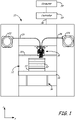
- FIGS. 1-3 illustrate system 10, which is an example extrusion-based additive manufacturing system for printing or otherwise building 3D parts, from the part material blends discussed herein, in a manner that controls the crystallization kinetics, as discussed below.
- Suitable extrusion-based additive manufacturing systems for system 10 include fused deposition modeling systems developed by Stratasys, Inc., Eden Prairie, MN under the trademark "FDM”.
- system 10 may include chamber 12, platen 14, platen gantry 16, print head 18, head gantry 20, and consumable assemblies 22 and 24.
- Chamber 12 is an example enclosed build environment that contains platen 14 for printing 3D parts and support structures, where chamber 12 may be may be optionally omitted and/or replaced with different types of build environments.
- a 3D part and support structure may be built in a build environment that is open to ambient conditions or may be enclosed with alternative structures (e.g., flexible curtains).
- the interior volume of chamber 12 may be heated with heater 12h to reduce the rate at which the part and support materials solidify after being extruded and deposited (e.g., to reduce distortions and curling).
- Heater 12h may be any suitable device or assembly for heating the interior volume of chamber 12, such as by radiant heating and/or by circulating heated air or other gas (e.g., inert gases).
- heater 12h may be replaced with other conditioning devices, such as a cooling unit to generate and circulate cooling air or other gas.
- the particular thermal conditions for the build environment may vary depending on the particular consumable materials used.
- the heating may be localized rather than in an entire chamber 12.
- the deposition region may be heated in a localized manner.
- Example techniques for locally-heating a deposition region include heating platen 14 and/or with directing heat air jets towards platen 14 and/or the 3D parts/support structures being printed).
- the heating in chamber 12 and/or the localized deposition region anneals the printed layers of the 3D parts (and support structures) to partially relieve the residual stresses, thereby reducing curling of the 3D parts.
- Platen 14 is a platform on which 3D parts and support structures are printed in a layer-by-layer manner.
- platen 14 may also include a flexible polymeric film or liner on which the 3D parts and support structures are printed.
- print head 18 is a dual-tip extrusion head configured to receive consumable filaments from consumable assemblies 22 and 24 (e.g., via guide tubes 26 and 28) for printing 3D part 30 and support structure 32 on platen 14.
- Consumable assembly 22 may contain a supply of the part material for printing 3D part 30 from the part material.
- Consumable assembly 24 may contain a supply of a support material for printing support structure 32 from the given support material.
- Platen 14 is supported by platen gantry 16, which is a gantry assembly configured to move platen 14 along (or substantially along) a vertical z-axis.
- print head 18 is supported by head gantry 20, which is a gantry assembly configured to move print head 18 in (or substantially in) a horizontal x-y plane above chamber 12.
- platen 14 may be configured to move in the horizontal x-y plane within chamber 12, and print head 18 may be configured to move along the z-axis.
- Other similar arrangements may also be used such that one or both of platen 14 and print head 18 are moveable relative to each other.
- Platen 14 and print head 18 may also be oriented along different axes. For example, platen 14 may be oriented vertically and print head 18 may print 3D part 30 and support structure 32 along the x-axis or the y-axis.
- System 10 also includes controller 34, which is one or more control circuits configured to monitor and operate the components of system 10.
- controller 34 may communicate over communication line 36 with chamber 12 (e.g., with a heating unit for chamber 12), print head 18, and various sensors, calibration devices, display devices, and/or user input devices.
- controller 34 may also communicate with one or more of platen 14, platen gantry 16, head gantry 20, and any other suitable component of system 10. While illustrated as a single signal line, communication line 36 may include one or more electrical, optical, and/or wireless signal lines, allowing controller 34 to communicate with various components of system 10. Furthermore, while illustrated outside of system 10, controller 34 and communication line 36 may be internal components to system 10.
- System 12 and/or controller 34 may also communicate with computer 38, which is one or more computer-based systems that communicates with system 12 and/or controller 34, and may be separate from system 12, or alternatively may be an internal component of system 12.
- Computer 38 includes computer-based hardware, such as data storage devices, processors, memory modules and the like for generating and storing tool path and related printing instructions. Computer 38 may transmit these instructions to system 10 (e.g., to controller 34) to perform printing operations. Controller 34 and computer 38 may collectively be referred to as a controller assembly for system 10.
- FIG. 2 illustrates a suitable device for print head 18, as described in Leavitt, U.S. Patent No. 7,625,200 .
- Additional examples of suitable devices for print head 18, and the connections between print head 18 and head gantry 20 include those disclosed in Crump et al., U.S. Patent No. 5,503,785 ; Swanson et al., U.S. Patent No. 6,004,124 ; LaBossiere, et al., U.S. Patent Nos. 7,384,255 and 7,604,470 ; Batchelder et al., U.S. Patent No. 7,896,209 ; and Comb et al., U.S. Patent No. 8,153,182 .
- print head 18 is an interchangeable, single-nozzle print head
- suitable devices for each print head 18, and the connections between print head 18 and head gantry 20 include those disclosed in Swanson et al., U.S. Patent Application Publication No. 2012/0164256 .
- print head 18 includes two drive mechanism 40 and 42, two liquefier assemblies 44 and 46, and two nozzles 48 and 50.
- the part material and the support material each preferably have a filament geometry for use with print head 18.
- the part material may be provided as filament 52.
- the part material of the present disclosure may be provided in powder or pellet form for use in an auger-pump print head, such as disclosed in Bosveld et al., U.S. Publication No. 2013/0333798 .
- controller 34 may direct wheels 54 of drive mechanism 40 to selectively draw successive segments filament 52 from consumable assembly 22 (via guide tube 26), and feed filament 52 to liquefier assembly 44.
- Liquefier assembly 44 may include liquefier tube 56, thermal block 58, heat shield 60, and tip shield 62, where liquefier tube 56 includes inlet end 64 for receiving the fed filament 52.
- Nozzle 48 and tip shield 62 are accordingly secured to outlet end 66 of liquefier tube 56, and liquefier tube 56 extends through thermal block 58 and heat shield 60.
- thermal block 58 heats liquefier tube 56 to define heating zone 68.
- the heating of liquefier tube 56 at heating zone 68 melts the part material of filament 52 in liquefier tube 56 to form melt 70.
- the upper region of liquefier tube 56 above heating zone 68, referred to as transition zone 72, is not directly heated by thermal block 58. This generates a thermal gradient or profile along the longitudinal length of liquefier tube 56.
- the molten portion of the part material forms meniscus 74 around the unmelted portion of filament 52.
- the downward movement of filament 52 functions as a viscosity pump to extrude the part material of melt 70 out of nozzle 48 as extruded roads to print 3D part 30 in a layer-by-layer manner.
- thermal block 58 heats liquefier tube 56 at heating zone 68
- cooling air may also be blown through a manifold 76 toward inlet end 64 of liquefier tube 56, as depicted by arrows 78.
- Heat shield 60 assists in directing the air flow toward inlet end 64.
- the cooling air reduces the temperature of liquefier tube 56 at inlet end 64, which prevents filament 52 from softening or melting at transition zone 72.
- controller 34 may servo or swap liquefier assemblies 44 and 46 between opposing active and stand-by states. For example, while liquefier assembly 46 is servoed to its active state for extruding the support material to print a layer of support structure 32, liquefier assembly 44 is switched to a stand-by state to prevent the part material from being extruded while liquefier assembly 46 is being used. After a given layer of the support material is completed, controller 34 then servoes liquefier assembly 46 to its stand-by state, and switches liquefier assembly 44 to its active state for extruding the part material to print a layer of 3D part 30. This servo process may be repeated for each printed layer until 3D part 30 and support structure 32 are completed.
- drive mechanism 42, liquefier assembly 46, and nozzle 50 may operate in the same manner as drive mechanism 40, liquefier assembly 44, and nozzle 48 for extruding the support material.
- drive mechanism 40 may draw successive segments of the support material filament from consumable assembly 24 (via guide tube 28), and feed the support material filament to liquefier assembly 46.
- Liquefier assembly 46 thermally melts the successive segments of the received support material filament such that it becomes a molten support material. The molten support material may then be extruded and deposited from nozzle 50 as a series of roads onto platen 14 for printing support structure 32 in a layer-by-layer manner in coordination with the printing of 3D part 30.
- the part material composition ally includes a blend of one or more semi-crystalline polymers and one or more secondary materials that retard crystallization of the semi-crystalline polymer(s).
- the secondary material(s) include one or more amorphous polymers that are at least partially miscible with the semi-crystalline polymer(s).
- the following discussion is made with reference to the secondary material(s) as amorphous polymer(s) with the understanding that the part material may alternatively include other non-amorphous polymer(s) to retard crystallization of the semi-crystalline polymer(s). Nonetheless, amorphous polymer(s) are preferred as they may also provide additional desired characteristics to the part material.
- the semi-crystalline polymer(s) and the amorphous polymer(s) are substantially miscible with each other.
- the substantially miscible blend may exhibit a co-continuous phase of the semi-crystalline polymer(s) and the amorphous polymer(s), or more preferably a single continuous phase of the semi-crystalline polymer(s) and the amorphous polymer(s). While not wishing to be bound by theory, it is believed that this miscibility allows the amorphous polymer(s) to physically impede the semi-crystalline polymer(s) from forming crystalline regions, which accordingly retards crystallization.
- the amorphous polymer(s) of the part material have substantially no measurable melting points (less than 5 calories/gram) using differential scanning calorimetry (DSC) pursuant to ASTM D3418-08.
- the semi-crystalline polymer(s) of the part material have measureable melting points (5 calories/gram or more) using DSC pursuant to ASTM D3418-08.
- the part material may also optionally include one or more additives dispersed in the blend.
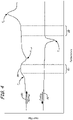
- FIG. 4 illustrates a DSC plot for an exemplary part material of the present disclosure having a substantially miscible blend of one or more semi-crystalline polymers and one or more amorphous polymers.
- the DSC pot in FIG. 4 shows the various thermal transitions that the part material may exhibit.
- the part material produces a heating profile 80 with a glass transition temperature ( T g ), a cold crystallization temperature ( T c,cold ), and a melting temperature ( T m ).
- T g glass transition temperature refers to the point along curve 80 where the part material undergoes a second-order transition to achieve an increase in its heat capacity.
- the semi-crystalline copolymer or blend may consist essentially of semi-crystalline polymers that exhibit substantial or complete miscibility. This may be the case for closely related polymers that are synthesized using (i) one or more base monomers, and (ii) a sizable fraction of one or more monomers that are structural or optical isomers of the base monomer(s) usually used in the synthesis. Other options include additional, unrelated monomers added in sufficient amounts to substantially alter the glass transition temperature, crystallization temperatures, re-crystallization temperatures, melting points, and/or enthalpies of fusion, as measured during heating or cooling at a specified, constant rate.
- Examples of some suitable techniques for these embodiments include controlling the level of d-lactide and 1-lactide incorporated into a final polylactic acid polymer to achieve a poly-DL-lactide.
- the DL polylactic acid copolymer has slower crystallization kinetics and may even exhibit characteristics of a completely amorphous polymer.
- PEKK polyetherketoneketone
- a third useful example includes the synthesis of polyesters, specifically those based on a poly(ethyleneterephthalate) polymer.
- some isophthalic moeities may be used in place of a terephthalic moeities to impart similar adjustments in crystallinity and crystallization behavior as discussed above for PEKK.
- one or more glycols may be exchanged with one or more ethylene glycols, propylene glycols, and/or butylene glycols, such as cyclohexanedimethanol, for example, to achieve similar effects.
- the cold crystallization temperature T c,cold typically occurs due to the increased mobility of the polymer molecules after exceeding the glass transition temperature T g , which allows a portion of the semi-crystalline polymer(s) to form crystalline regions. Because the crystallization is an exothermic process, it releases thermal energy based on a first-order transition, as illustrated by the inverted peak in heating profile 80.
- the melting temperature T m is the temperature at which the part material fully liquefies, also based on a first-order transition. Typically, the part material is quickly heated past its melting temperature T m in liquefier assembly 44 for extrusion. As such, during this point in the process, the glass transition temperature T g and the cold crystallization temperature T c,com are not overly relevant to the crystallization state of the extrudate, other than for potential melt flow and temperature control aspects in liquefier assembly 44.
- the DSC plot in FIG. 4 also includes a cooling profile 82, which illustrates hot crystallization temperature T c,hot , and describes the crystallization kinetics of the part material as it cools down from its melting temperature T m .
- the extruded part material may deposit as roads onto the previously-formed layer of 3D part 30, and begin cooling down.
- the part material begins to follow cooling profile 82 at a cooling rate that depends on the environment temperature that 3D part 30 is printed in (e.g. in chamber 12), as well as the particular composition of the part material and the size of 3D part 30.
- the layers of 3D part 30 are printed in chamber 12 (or at least in a locally-heated deposition region) that is maintained at a temperature between a solidification temperature and the cold crystallization temperature T c,cold of the part material. This can anneal the successively-printed printed layers, allowing them to cool down and solidify slowly, which can partially relieve the residual stresses.
- chamber 12 or the locally-heated deposition region is maintained at a temperature between a solidification temperature and the glass transition temperature T g of the part material.
- T g glass transition temperature
- chamber 12 or the locally-heated deposition region is maintained at a temperature within an annealing window 84 having a lower limit at about the glass transition temperature T g of the part material and an upper limit that is less than the cold crystallization temperature T c,cold of the part material.
- annealing window 84 preferably encompasses the plateau region 86 of DSC heating curve 80, which is above the increased slope for the glass transition temperature T g and below the decreased slope for the cold crystallization temperature T c,cold .
- chamber 12 may be omitted, and the part material may be printed at room temperature (e.g., 25°C).
- room temperature e.g. 25°C.
- the substantially-miscible blends for the part material modify the glass transition temperature T g of the part material from that of the amorphous polymer(s), typically flowing the Flory-Fox Equation.
- the substantially-miscible blends may also decrease the hot crystallization temperature T c,hot of the part material from that of the pure semi-crystalline polymer(s). This provides a unique advantage in that the cumulative amount of crystallization for the part material upon cooling can be reduced, which accordingly allows the printed layers of the part material to have low levels of crystallinity.
- the part material upon being extruded and deposited from nozzle 48, the part material preferably is quickly cooled down past its hot crystallization temperature T c,hot to its annealing temperature below the cold crystallization temperature 7 c,cold of the part material (e.g., within annealing window 84). This effectively supercools the part material down below its cold crystallization temperature T c,cold .
- the level of crystallinity can be controlled based on the particular annealing temperature used. For instance, if more amorphous properties are desired, the annealing temperature may be set to be set within about 5°C of the glass transition temperature T g of the part material. Alternatively, if more crystalline properties are desired, the annealing temperature may be set to be set within 5°C of the cold crystallization temperature T c,cold of the part material. Furthermore, any intermediate amorphous-crystalline variation may be achieved by maintaining the annealing temperature at a selected temperature within annealing window 84.
- the incorporation of the amorphous polymer(s) also assists in physically impeding the semi-crystalline polymer(s) from grouping together in ordered arrangements to form crystalline regions.
- the short residence time in the region between its hot crystallization temperature T c,hot and its cold crystallization temperature T c,cold combined with the crystallization impedance, preferably minimizes or otherwise reduces the formation of crystalline regions in the part material.
- a given pure semi-crystalline polymer i.e., non-blend
- T c,hot and its cold crystallization temperature T c,cold hot crystallization temperature
- T c,cold cold crystallization temperature
- the crystallization impedance of the part material blend may require more than a 10 to 20-fold increase in the time required to fully crystallize.
- the part material when the part material resides in this region between its hot crystallization temperature T c,hot and its cold crystallization temperature T c,cold for about one second, it may only form about 1-3% of its fully-achievable crystallinity, for example.
- the supercooled part material exhibits a translucent, substantially non-opaque appearance. This is an indication that crystallinity has been significantly retarded since crystalline regions typically modify the indices of refraction of the extruded layers to render them opaque.
- the minimized or reduced crystallization correspondingly reduces the discontinuous changes in volume of the semi-crystalline polymer(s), thereby reducing the residual stresses on the printed layers. Furthermore, holding the printed layers at the annealing temperature (e.g., within annealing window 84) also anneals the successively-printed printed layers, allowing them to cool down and solidify slowly, which can relieve the residual stresses typically associated with amorphous materials.
- the part material is preferably supercooled quickly from its extrusion temperatures down to an annealing temperature in annealing window 84, and then held within annealing window 84 for a suitable duration to relieve the residual stresses.
- the printed layers of the part material may be cooled down further (e.g., below its glass transition temperature T g and/or its solidification temperature).
- Another interesting property of the part materials of the present disclosure is that, despite the minimized or reduced crystallinity, the crystallization that does occur during the supercooling generates a sufficient amount of heat to induce extra or increased molecular reptation at the extrudate-part interface.
- the heat produced during the limited crystallization-exothermic reaction allows the polymer molecules at the extrudate-part interface to move and become highly entangled. It has been observed that, due to the heat of fusion of the extruded roads, the rate of temperature decay of the extruded part material can change, and cool down at a slower rate.
- 3D part 30 may have mechanical properties (e.g., strengths and ductilities) similar to those of semi-crystalline polymer(s).
- 3D part 30 may then be cooled down to room temperature and optionally undergo one or more post-printing processes. Alternatively, 3D part 30 may be reheated in a post-printing crystallization step. In this step, 3D part 30 may be heated up to about its cold crystallization temperature T c,cold for a sufficient duration to induce further crystallization of the semi-crystalline polymer(s). Examples of suitable annealing durations in the post-printing crystallization step range from about 30 minutes to 3 hours, and may vary depending on the dimensions of each 3D part 30 and the part material compositions.
- examples of suitable annealing temperatures in the post-printing crystallization step range from about the cold crystallization temperature T c,cold of the part material to within about 10°C above its cold crystallization temperature T c,cold , and more preferably to within about 5°C above its cold crystallization temperature T c,cold .
- the post-printing crystallization step can further increase the mechanical, thermal, and chemical resistance properties of 3D part 30 due to the increased formation of the crystalline regions. Additionally, this post-printing crystallization step is performed on 3D part 30 as a whole (i.e., congruent crystallization), rather than as the layers are individually printed. As such, any potential shrinkage on 3D part 30 from the formation of the crystalline regions occurs in a uniform manner similar to the effects in an injection molding process, rather than in a layer-by-layer manner that can otherwise result in curling effects.
- 3D part 30 is preferably de-coupled from platen 14 (e.g., from a build sheet of platen 14), allowing 3D part 30 to be further crystallized without being restricted by any non-shrinkable build sheet.
- a 3D part 30 having a translucent, substantially non-opaque appearance is an indication that crystallinity has been retarded during the printing operation.
- the transformation from the translucent, substantially non-opaque appearance to an opaque appearance is an indication that the part material of 3D part 30 has undergone significant crystallization in the post-printing crystallization step.
- the resulting 3D part 30 may then be cooled down to room temperature and optionally undergo one or more post-printing processes.
- the post-printing crystallization step may be performed in chamber 12 of system 10, or alternatively in a separate annealing oven.
- a separate annealing oven may be preferred in many situations, such as when support structure 32 needs to be removed prior to the post-printing annealing step and/or when system 10 needs to be used for subsequent printing operations.
- a printing farm of multiple systems 10 may operate in coordination with one or more separate annealing ovens to maximize the duty cycles of the systems 10.
- the above-discussed control of the crystallization kinetics of the part material requires the part material to have a blend of one or more semi-crystalline polymers and one or more secondary materials, preferably amorphous polymer(s), that retard crystallization of the semi-crystalline polymer(s) and that are at least partially miscible (or more preferably, substantially miscible) with the semi-crystalline polymer(s).
- amorphous polymer(s) that retard crystallization of the semi-crystalline polymer(s) and that are at least partially miscible (or more preferably, substantially miscible) with the semi-crystalline polymer(s).
- part material may include one or more copolymers having chain segments corresponding to the semi-crystalline polymer(s) and the secondary material(s), where the chain segments of the secondary material(s) retard the crystallization of the chain segments of the semi-crystalline polymeric material(s).
- the part material is a polyamide part material that compositionally includes a polyamide blend of one or more semi-crystalline polyamides, one or more amorphous polyamides, and optionally, one or more additives dispersed in the polyamide blend.
- the semi-crystalline polyamide(s) may include polyamide homopolymers and copolymers derived from monomers that include caprolactam, diamines in combination with monomers that include dicarboxylic acids, and mixtures thereof.
- the diamine monomers and the dicarboxylic acid monomers are each preferably aliphatic monomers, and more preferably are each acyclic aliphatic monomers.
- the diamine monomers and/or the dicarboxylic acid monomers may include aromatic or cycloaliphatic groups while maintaining crystalline domains.
- the semi-crystalline polyamide(s) may include cyclic groups in grafted pendant chains (e.g., maleated groups), as discussed below.
- Preferred polyamide homopolymers and copolymers for the semi-crystalline polyamide(s) may be represented by the following structural formulas: where R 1 , R 2 , and R 3 may each be a hydrocarbon chain having 3-12 carbon atoms.
- the hydrocarbon chains for R 1 , R 2 , and R 3 may be branched (e.g., having small alkyl groups, such as methyl groups) or unbranched, and which are preferably aliphatic, acyclic, saturated hydrocarbon chains.
- bracketed formula repeats for n units, where n is a whole number that may vary depending on the molecular weight of the given polymer.
- bracketed formulas may be the same between the repeating units (i.e., a homopolymer) or may be vary between the repeating units (i.e., copolymer).
- R 1 may be the same structure for each repeating unit to provide a homopolymer, or may be two or more different structures that repeat in an alternating copolymer manner, a random copolymer manner, a block copolymer manner, a graft copolymer manner (as discussed below), or combinations thereof.
- Preferred polyamides for the semi-crystalline polyamide(s) include nylon-type materials such as polycarpolactum (PA6), polyhexamethyleneaidpamide (PA6,6), polyhexamethylenenonamide (PA6,9), polyhexamethylenesebacamide (PA6,10), polyenantholactum (PA7), polyundecanolactum (PA11), polylaurolactam (PA12), and mixtures thereof. More preferably, the polyamides for the semi-crystalline polyamide(s) include PA6; PA6,6; and mixtures thereof. Examples of suitable semi-crystalline polyamide(s) having aromatic groups include semi-crystalline polyamides of aliphatic diamines and isophthalic acid and/or terephthalic acid (e.g., semi-crystalline polyphthalamides).
- the semi-crystalline polyamide(s) are graft semi-crystalline polyamide(s), each having a polyamide backbone and one or more impact modifiers grafted to the backbone.
- the impact modifiers may include polyolefin-chain monomers and/or elastomers having coupling groups configured to graft the monomers to the polyamide backbone.
- Suitable coupling groups for the impact modifiers include piperidine groups, acrylic/methacrylic acid groups, maleic anhydride groups, epoxy groups.
- Preferred coupling groups include maleic anhydride groups and epoxy groups, such as those respectively represented by the following structural formulas: where R 4 and R 5 may each be a hydrocarbon chain having 2-20 carbon atoms, and more preferably 2-10 carbon atoms; and where R 6 may be a hydrocarbon chain having 1-4 carbon atoms.
- the hydrocarbon chains of R 4 , R 5 , and R6 may each be branched or unbranched.
- preferred impact modifiers include maleated polyethylenes, maleated polypropylenes, and mixtures thereof.
- preferred impact modifiers include maleated ethylene propylene diene monomers (EPDM).
- suitable commercial impact modifiers include those available under the tradenames LOTADER from Arkema Inc., Philadelphia, PA; those under the tradename ELVALOY PTW, FUSABOND N Series, and NUCREL from E. I. du Pont de Nemours and Company, Wilmington, DE; and those under the tradename ROYALTURF from Chemtura Corporation, Philadelphia, PA.
- suitable graft semi-crystalline polyamides include those commercially available under the tradename ULTRAMID from BASF Corporation, Florham Park, NJ; and those under the tradename GRILAMID from EMS-Chemie, Inc., Sumter, SC (business unit of EMS-Grivory).
- the grafted impact modifiers may constitute from about 1% to about 20% by weight of the graft semi-crystalline polyamide(s). In some embodiments, the grafted impact modifiers constitute from about 5% to about 15% by weight of the graft semi-crystalline polyamide(s). In embodiments that incorporate the graft semi-crystalline polyamide(s), the graft semi-crystalline polyamide(s) may constitute from about 50% to 100% by weight of the semi-crystalline polyamide(s) in the part material, more preferably from about 80% to 100% by weight, and even more preferably from about 95% to 100% by weight. In some preferred embodiments, the semi-crystalline polyamide(s) of the PA material consist essentially of the graft semi-crystalline polyamide(s).
- the semi-crystalline polyamide(s) preferably have a molecular weight range that renders them suitable for extrusion from print head 18, which may be characterized by their melt flow indices.
- Preferred melt flow indices for the semi-crystalline polyamide(s) range from about 1 gram/10 minutes to about 40 grams/10 minutes, more preferably from about 3 grams/10 minutes to about 20 grams/10 minutes, and even more preferably from about 5 grams/10 minutes to about 10 grams/10 minutes where the melt flow index, as used herein, is measured pursuant to ASTM D1238-10 with a 2.16 kilogram weight at a temperature of 260°C.
- the PA material also compositionally includes one or more amorphous polyamides that are preferably miscible with the semi-crystalline polyamide(s).
- the amorphous polyamide(s) may include polyamide homopolymers and copolymers derived from monomers that include diamines in combination with monomers that include dicarboxylic acids, which are preferably cycloaliphatic and/or aromatic monomers.
- the diamine monomers and/or the dicarboxylic acid monomers may include aliphatic groups (e.g., acyclic aliphatic groups) while maintaining amorphous properties.
- Preferred polyamide homopolymers and copolymers for the amorphous polyamide(s) may be represented by the following structural formulas: where R 7 and R 10 may each be a hydrocarbon chain having 3-12 carbon atoms.
- the hydrocarbon chains for R 7 and R 10 may be branched (e.g., having small alkyl groups, such as methyl groups) or unbranched, and which are preferably aliphatic, acyclic, saturated hydrocarbon chains.
- R 8 , R 9 , R 11 , and R 12 may each be a hydrocarbon chain having 5-20 carbon atoms, which may be branched (e.g., having alkyl groups, such as methyl groups) or unbranched, and each of which includes one or more aromatic groups (e.g., benzene groups), one or more cycloaliphatic groups (e.g., cyclohexane groups), or combinations thereof.
- aromatic groups e.g., benzene groups
- cycloaliphatic groups e.g., cyclohexane groups
- Preferred polyamides for the amorphous polyamide(s) include nylon-type materials such as polyamides of hexamethylenediamine, isophthalic acid, terephthalic acid, and adipic acid (PA6i/6T); polyamides of PA12; 3,3-dimethyl-4,4-diaminodicyclohexylmethane, and isophthalic acid (PA12/MACMI); polyamides of PA12; 3,3-dimethyl-4,4-diaminodicyclohexylmethane, and terephthalic acid (PA12/MACMT); (PA12/MACMI/MACMT); PA6i; PA12/MACM36; PANDT/INDT; polyamides of trimethylhexamethylenediamine and terephthalic acid (PA6/3T); polyamides of cycloaliphaticdiamine and dodecanedioic acid; amorphous polyamides of aliphatic diamines and isophthalic acid
- the amorphous polyamide(s) may be graft amorphous polyamide(s), each having a polyamide backbone and one or more impact modifiers grafted to the backbone.
- Preferred impact modifiers for grafting to the amorphous polyamide(s) include those discussed above for the graft semi-crystalline polyamide(s), such as polyolefin-chain monomers and/or elastomers having coupling groups configured to graft the monomers to the polyamide backbone (e.g., piperidine groups, acrylic/methacrylic acid groups, maleic anhydride groups, and epoxy groups).
- Suitable concentrations of the grafted impact modifiers in the graft amorphous polyamide(s), and suitable concentrations of the graft amorphous polyamides relative to the entirety of amorphous polyamide(s) in the part material include those discussed above for the graft semi-crystalline polyamide(s).
- Preferred concentrations of the amorphous polyamide(s) in the polyamide blend range from about 30% to about 70% by weight, more preferably from about 40% to about 60% by weight, and even more preferably from about 45% to about 55% by weight, where the semi-crystalline polyamide(s) constitute the remainder of the polyamide blend. Accordingly, preferred ratios of the amorphous polyamide(s) to the semi-crystalline polyamide(s) range from about 3:7 to about 7:3, more preferably from about 4:6 to about 6:4, and even more preferably from about 4.5:5.5: to about 5.5:4.5.
- the part material includes a substantially miscible blend of one or more polyetherimides (PEI) and one or more semi-crystalline polyaryletherketones (PAEK), such as one or more polyetherketones (PEK), polyetheretherketones (PEEK), polyetherketoneketones (PEKK), polyetheretherketoneketones (PEEKK), polyetherketoneether-ketoneketones (PEKEKK), mixtures thereof, and the like, and more preferably one or more polyetheretherketones (PEEK).
- PEK polyetherimides
- PEEK polyetherketones
- PEKK polyetherketoneketones
- PEEKK polyetherketoneketones
- PEKEKK polyetherketoneether-ketoneketones
- Preferred concentrations of the polyaryletherketone(s) in this blend range from about 35% by weight to about 99% by weight, and more preferably from about 50% by weight to about 90% by weight, and even more preferably form about 60% by weight to about 80% by weight, where the polyetherimide(s) constitute the remainder of the blend.
- the part material includes a substantially miscible blend of one or more polyphenylsulfones (PPSU), polysulfones (PSU), and/or polyethersulfones (PES), with one or more semi-crystalline polyaryletherketones.
- Preferred concentrations of the polyphenylsulfone(s)/polysulfone(s)/polyethersulfone(s) in this blend range from about 1% by weight to about 65% by weight, and more preferably from about 20% by weight to about 50% by weight, where the polyaryletherketone(s) constitute the remainder of the blend.
- the part material includes a substantially miscible blend of one or more polycarbonates and one or more semi-crystalline polybutylene terephthalates (PBT) and/or one or more semi-crystalline polyethylene terephthalates (PET).
- PBT polybutylene terephthalates
- PET polyethylene terephthalates
- concentrations of the polycarbonate(s) in this blend range from about 30% by weight to about 90% by weight, and more preferably from about 50% by weight to about 70% by weight, where the polybutylene terephthalate(s)/polyethylene terephthalate(s) constitute the remainder of the blend.
- the part material includes a substantially miscible blend of one or more amorphous polyethylene terephthalates (e.g., glycol-modified polyethylene terephthalates) and one or more semi-crystalline polyethylene terephthalates.
- amorphous polyethylene terephthalates e.g., glycol-modified polyethylene terephthalates
- semi-crystalline polyethylene terephthalates e.g., polyethylene terephthalates
- concentrations of the amorphous polyethylene terephthalate(s) in this blend range from about 10% by weight to about 40% by weight, and more preferably from about 15% by weight to about 25% by weight, where the semi-crystalline polyethylene terephthalate(s) constitute the remainder of the blend.
- the part material includes a substantially miscible blend of one or more amorphous polyaryletherketones and one or more semi-crystalline polyaryletherketones, such as one or more amorphous polyetherketoneketones (PEKK) and one or more semi-crystalline polyetherketoneketones (PEKK).
- Preferred concentrations of the amorphous polyaryletherketones(s) in this blend range from about 30% by weight to about 90% by weight, and more preferably from about 50% by weight to about 70% by weight, where the semi-crystalline polyaryletherketones(s) constitute the remainder of the blend.
- the part material may also include additional additives, such as colorants, fillers, plasticizers, impact modifiers, and combinations thereof.
- additional additives such as colorants, fillers, plasticizers, impact modifiers, and combinations thereof.
- colorants preferred concentrations of the colorants in the part material range from about 0.1% to about 5% by weight.
- Suitable colorants include titanium dioxide, barium sulfate, carbon black, and iron oxide, and may also include organic dyes and pigments.
- preferred concentrations of the fillers in the part material range from about 1% to about 45% by weight for some fillers (e.g., glass and carbon fillers), and up to about 80% by weight for other fillers, such as metallic and ceramic fillers.
- suitable fillers include calcium carbonate, magnesium carbonate, glass spheres, graphite, carbon black, carbon fiber, glass fiber, talc, wollastonite, mica, alumina, silica, kaolin, silicon carbide, zirconium tungstate, soluble salts, metals, ceramics, and combinations thereof.
- the polymer blend preferably constitutes the remainder of the part material.
- the polymer blend may constitute from about 55% to 100% by weight of the part material, and more preferably from about 75% to 100% by weight.
- the polymer blend constitutes from about 90% to 100% by weight of the part material, more preferably from about 95% to 100% by weight.
- the part material consists essentially of the polymer blend, and optionally, one or more colorants and/or anti-oxidants.
- the polymer blend is also substantially homogenous, allowing each portion of the part material used in an additive manufacturing system to consistently exhibit the same thermal and physical properties.
- the flow rate of the molten part material (i.e., melt 70) from nozzle 48 is controlled by the rate at which filament 52 enters liquefier tube 56, and the melting rate of filament 52 within heating zone 68.
- System 10 may operate with preset instructions for extruding melt 70 at desired flow rates based on tool path geometries. These preset instructions are preferably based on the thermal properties of the part material, namely the melting rate and viscosity of the part material, as well as the crystallization kinetics of the part material.
- filament 52 is preferably manufactured from a part material having a substantially homogenous polymer blend of the semi-crystalline polymer(s) and the secondary material(s) (e.g., amorphous polymer(s)).
- the additive(s) are preferably dispersed in the polymer blend in a substantially uniform manner.
- the above-discussed method may also be utilized with electrophotography-based additive manufacturing systems and selective laser sintering systems.
- the part material may be provided in powder form for use in an electrophotography-based additive manufacturing system, such as those disclosed in Hanson et al., U.S. Publication Nos. 2013/0077996 and 2013/0077997 , and Comb et al., U.S. Publication Nos. 2013/0186549 and 2013/0186558 .
- the electrophotography-based additive manufacturing systems preferably operate with layer transfusion assemblies that transfuse each successively-developed layer based on interlayer polymer entanglement (i.e., reptation).
- layer transfusion assemblies that transfuse each successively-developed layer based on interlayer polymer entanglement (i.e., reptation).
- the above-discussed method for controlling the crystallization kinetics of the part material for the extrusion-based additive manufacturing systems may also be used in the same manner with the electrophotography-based additive manufacturing systems.
- selective laser sintering systems may print 3D parts from nylon materials in a manner in which a nylon material is held in a gelatinous, undercooled amorphous state between the melting temperature and the hot crystallization temperature of the nylon material.
- nylon materials typically have small temperature windows between their melting temperatures and the hot crystallization temperatures, rendering it difficult to hold the printed layers in this amorphous state after being melted with a laser beam.
- the substantially miscible blends for the part material of the present disclosure decrease the hot crystallization temperature T c,hot of the part material from that of the semi-crystalline polymer(s). Conversely, the melting temperature T m of the part material remains substantially unchanged.
- the substantially miscible blend for the part material widens the operating window, referred to as operating window 88 in FIG. 4 , in which the printed layers may be held in the gelatinous, undercooled amorphous state to prevent warping and distortions.
- the powder materials may be selectively melted with the laser beam and held within this operating window 88 until the printing operation is completed.
- the whole 3D part 30 may then be cooled down in a conventional manner.
- the part material may be provided in powder form for use in other powder-based additive manufacturing systems.
- this technique may also be utilized in extrusion-based and/or electrophotography-based additive manufacturing systems. This can accordingly produce 3D parts having high heat deflection temperatures, which can be beneficial for use with soluble support materials.
- Part materials of Examples 1-4 and Comparative Examples A and B were prepared as PEEK/PEI blends with varying weight ratios. Each part material was then analyzed using DSC to determine the glass transition temperature T g , cold crystallization temperature T c,cold , melting temperature T m , and hot crystallization temperature T c,hot . Table 1 lists the DSC results for the tested part materials with the PEEK/PEI ratios, where the temperatures were reported in degrees Celsius.
- the results in Table 1 show the relative changes in the glass transition temperature T g , cold crystallization temperature T c,cold , melting temperature T m , and hot crystallization temperature T c,hot for the different PEEK/PEI ratios.
- the glass transition temperature T g increases substantially with the increased concentration of PEI.
- the cold crystallization temperature T c,cold and the hot crystallization temperature T c,hot converged closer together with the increased concentration of PEI, but the melting temperature T m remained relatively the same (e.g., 4 degree drop between Examples 1 and 3, versus a 22 degree drop for the hot crystallization temperature Tc , hot ).
- the differences between the glass transition temperatures T g and the cold crystallization temperatures T c,cold for Examples 1-3 provide suitable annealing windows (e.g., annealing window 84) for printing 3D parts with extrusion-based and/or electrophotography-based additive manufacturing systems.
- suitable annealing windows e.g., annealing window 84
- melting temperatures T m and the hot crystallization temperature T c,hot for Examples 1-3 provide suitable operating windows (e.g., operating window 88) for printing 3D parts with selective laser sintering systems.
- the DSC testing also involved reheating the part materials after the cooling step to simulate a post-printing crystallization step.
- the part materials of Examples 2 and 3 each exhibited two different glass transition temperatures T g .
- the part material of Example 2 had a first glass transition temperature of 164°C and a second glass transition temperature of 209°C.
- the part material of Example 2 had a first glass transition temperature of 167°C and a second glass transition temperature of 210°C. This phenomenon is believed to be caused by the PEEK and PEI polymers separating upon crystallization, such that the PEI was not incorporated in the PEEK crystalline regions.
- Example 2 show that the part materials of Examples 1-3 exhibit high levels of exothermic energy upon crystallization.
- the part material of Example 4 appeared to generate very little crystallization. However, this is believed to be due to a kinetic phenomenon that would disappear with slower cooling.
- the part material of Example 4 exhibited a melting point (as shown above in Table 1) and turned opaque upon reheating (i.e., re-crystallization).
- Example 5 A part material of Example 5 having a PEEK/PEI weight ratio of 60/40 was compounded into cylindrical filaments having an average diameter of about 1.778 mm (0.07 inches) and wound onto spools of consumable assemblies.
- the consumable assembly was loaded to an extrusion-based additive manufacturing system commercially available from Stratasys, Inc., Eden Prairie, MN under the trademarks "FDM” and "FORTUS 400mc”.
- the filament was then fed from the consumable assembly to print head liquefier assembly of the system, melted, and extruded from print head nozzle to print 3D parts in a heated chamber maintained at 160°C (i.e., below its glass transition temperatures T g ).
- FIG. 5 illustrates pellets and the printed 3D parts from the part material of Example 5.
- the printed 3D part and associated pellets exhibited a golden, translucent appearance due to the low levels of crystallinity.
- a corresponding 3D part and portions of the pellets were also reheated to about 200°C (i.e., a post-printing crystallization process) for a sufficient duration to re-crystallize the PEEK in the part material.
- the annealed 3D part and pellets each exhibited an opaque appearance, which was more tan/whitish in color than the golden color of the non-re-crystallized part/pellets.
- Example 6 Part materials of Example 6 were prepared as polyamide blends, where the semi-crystalline polyamide was a graft PA12 polyamide commercially available under the tradename GRILAMID L16 from EMS-Chemie, Inc., Sumter, SC (business unit of EMS-Grivory), and the amorphous polyamide was a PA12 polyamide commercially available under the tradename GRILAMID TR90 from EMS-Chemie, Inc., Sumter, SC (business unit of EMS-Grivory).
- GRILAMID L16 from EMS-Chemie, Inc.
- SC business unit of EMS-Grivory
- the semi-crystalline polyamide concentration in the part material ranged from 27.2% - 28.2% by weight, and the amorphous polyamide concentration in the part material ranged from 65.2% - 66.2% by weight, for a blend ratio of about 70:30 of the amorphous polyamide to semi-crystalline polyamide.
- the part material also included an impact modifier having a concentration in the part material ranging from 4.5% - 5.5% by weight, and an anti-oxidant having a concentration in the part material ranging from 0.03% - 0.13% by weight.
- Example 6 Each part material of Example 6 was analyzed using DSC to provide an average glass transition temperature T g of 55°C, an average cold crystallization temperature T c,cold of 130°C, an average melting temperature T m of 178°C, and an average hot crystallization temperature T c,hot of 148°C. Each part material was also compounded into cylindrical filaments having an average diameter of about 1.778 mm (0.07 inches) and wound onto spools of consumable assemblies.
- the consumable assembly was loaded to an extrusion-based additive manufacturing system commercially available from Stratasys, Inc., Eden Prairie, MN under the trademarks "FDM” and "FORTUS 400mc”.
- the liquefier temperature was set to 355°C and the heated chamber temperature was set to 80°C, 100°C, or 120°C, depending on the 3D part geometry being printed.
- Each 3D part exhibited good dimensional stability and low levels of crystallinity.
- Example 7 A part materials of Example 7 was prepared as an impact-modified PET blend, where the semi-crystalline PET was a polyethylene terephthalate copolymer commercially available under the tradename "SKYPET BR" from SK Chemicals, South Korea, and the amorphous PET was a glycol-modified polyethylene terephthalate commercially available under the tradename "SKYGREEN S2008” from SK Chemicals, South Korea.
- the part material included 76% by weight of the semi-crystalline PET, 19% by weight of the amorphous PET, and 5% by weight of an impact modifier commercially available under the tradename "ELVALOY PTW” from E.I. du Pont de Nemours and Company, Wilmington, DE.
- Example 7 The part material of Example 7 was compounded into cylindrical filaments having an average diameter of about 1.778 mm (0.07 inches) and wound onto spools of consumable assemblies. For each run, the consumable assembly was loaded to an extrusion-based additive manufacturing system commercially available from Stratasys, Inc., Eden Prairie, MN under the trademarks "FDM” and "FORTUS 400mc".
- the filament was melted and extruded from a print head at a temperature of 320°C into a heated build chamber, where the temperature of the build chamber was held at 90°C, 100°C, 110°C, and 120°C for four different runs.
- the part material had a glass transition temperature of about 78°C. As such, these different temperatures tested how the different annealing windows affected the level of crystallinity in the resulting 3D part.
- each of the four 3D parts was slowly heated and the resulting modulus was measured, as illustrated in FIG. 6 .
- the part material annealed at 90°C maintained a mostly-amorphous mechanical behavior
- the part material annealed at 120°C maintained a mostly-semi-crystalline mechanical behavior.
- the part materials annealed at 100°C and 110°C fell between these two end points.
- the part material of Example 8 included 70% by weight of the PET blend of Example 7 and 30% by weight of a glass-based filler.
- the part material of Example 8 was also printed as discussed above for the part materials of Example 6, where the heated chamber was held at only 80°C to maintain a mostly-amorphous mechanical behavior.
- a portion of the 3D part samples were then reheated to about 135°C (i.e., a post-printing crystallization process) for a sufficient duration to re-crystallize the semi-crystalline PET in the part material.
- each 3D part sample was then slowly heated and the resulting modulus was measured, as illustrated in FIG. 8 , which also compares the results of the part material for Example 7 printed in the 120°C heated chamber. As shown in FIG. 8 , the post-printing crystallization process significantly increased the crystallinity of the part material compared to the initial samples.
Landscapes
- Engineering & Computer Science (AREA)
- Chemical & Material Sciences (AREA)
- Materials Engineering (AREA)
- Manufacturing & Machinery (AREA)
- Physics & Mathematics (AREA)
- Mechanical Engineering (AREA)
- Optics & Photonics (AREA)
- Thermal Sciences (AREA)
- General Physics & Mathematics (AREA)
- Crystallography & Structural Chemistry (AREA)
Claims (8)
- Procédé permettant d'imprimer une pièce tridimensionnelle avec un système de fabrication additive (10), le procédé comprenant :la fourniture d'un matériau de pièce comprenant dans sa composition un ou plusieurs polymères semicristallins et un ou plusieurs matériaux secondaires qui sont configurés pour retarder la cristallisation des un ou plusieurs polymères semicristallins, dans lequel les un ou plusieurs matériaux secondaires sont sensiblement miscibles avec les un ou plusieurs polymères semicristallins ;la fusion du matériau de pièce dans le système de fabrication additive (10) ;la formation d'au moins une partie d'une couche de la pièce tridimensionnelle à partir du matériau de pièce fondu dans un environnement de construction (12) ; etcaractérisé en ce que les un ou plusieurs polymères semicristallins sont polymérisés à partir d'un ou plusieurs monomères de base, et dans lequel les un ou plusieurs matériaux secondaires comprennent un ou plusieurs seconds polymères semicristallins polymérisés à partir d'un ou plusieurs monomères qui sont des isomères des un ou plusieurs monomères de base ;dans lequel le procédé comprend en outre l'étape consistant à maintenir l'environnement de construction (12) à une température de recuit qui est entre une température de transition vitreuse du matériau de pièce et une température de cristallisation par refroidissement du matériau de pièce.
- Procédé selon la revendication 1, dans lequel les un ou plusieurs polymères semicristallins et les un ou plusieurs seconds polymères semicristallins comprennent chacun un ou plusieurs polymères d'acide polylactique, un ou plusieurs polymères de polyéthercétonecétone, ou un ou plusieurs polyesters.
- Procédé permettant d'imprimer une pièce tridimensionnelle avec un système de fabrication additive (10), le procédé comprenant :la fourniture d'un matériau de pièce qui comprend dans sa composition un ou plusieurs polymères semicristallins et un ou plusieurs polymères amorphes qui sont sensiblement miscibles avec les un ou plusieurs polymères semicristallins ;la fusion du matériau de pièce dans le système de fabrication additive (10) ;caractérisé en ce que le procédé comprend en outre les étapes consistant à former des couches de la pièce tridimensionnelle à partir du matériau de pièce fondu en utilisant une technique de fabrication additive, dans lequel les couches sont formées dans une région (12) qui est maintenue à une température de recuit qui est de plus ou moins 10 °C d'une température de transition vitreuse du matériau de pièce ; etréchauffer la pièce tridimensionnelle imprimée à une ou plusieurs températures qui sont de plus ou moins 10 °C environ d'une température de cristallisation par refroidissement du matériau de pièce.
- Procédé selon la revendication 3, dans lequel la température de recristallisation est de plus ou moins 5 °C environ de la température de cristallisation par refroidissement du matériau de pièce.
- Procédé selon la revendication 3, dans lequel le réchauffage de la pièce tridimensionnelle imprimée aux une ou plusieurs températures est réalisé pendant au moins 30 minutes environ.
- Procédé selon la revendication 3, dans lequel l'étape de réchauffage est réalisée dans un four séparé par rapport au système de fabrication additive (10).
- Procédé selon la revendication 6, et comprenant en outre la séparation de la pièce tridimensionnelle d'une feuille de construction (14) utilisée pour recevoir les couches formées de la pièce tridimensionnelle.
- Procédé selon la revendication 3, dans lequel les un ou plusieurs polymères semicristallins comprennent un ou plusieurs polyamides semicristallins, et dans lequel les un ou plusieurs polymères amorphes comprennent un ou plusieurs polyamides amorphes.
Applications Claiming Priority (3)
| Application Number | Priority Date | Filing Date | Title |
|---|---|---|---|
| US201361909611P | 2013-11-27 | 2013-11-27 | |
| US14/532,465 US9527242B2 (en) | 2012-11-21 | 2014-11-04 | Method for printing three-dimensional parts wtih crystallization kinetics control |
| PCT/US2014/067093 WO2015081009A1 (fr) | 2013-11-27 | 2014-11-24 | Procédé d'impression de pièces tridimensionnelles avec contrôle cinétique de la cristallisation |
Publications (3)
| Publication Number | Publication Date |
|---|---|
| EP3074207A1 EP3074207A1 (fr) | 2016-10-05 |
| EP3074207B1 EP3074207B1 (fr) | 2019-04-10 |
| EP3074207B2 true EP3074207B2 (fr) | 2022-12-21 |
Family
ID=53181983
Family Applications (1)
| Application Number | Title | Priority Date | Filing Date |
|---|---|---|---|
| EP14820975.2A Active EP3074207B2 (fr) | 2013-11-27 | 2014-11-24 | Procédé d'impression de pièces tridimensionnelles avec contrôle cinétique de la cristallisation |
Country Status (9)
| Country | Link |
|---|---|
| US (3) | US9527242B2 (fr) |
| EP (1) | EP3074207B2 (fr) |
| JP (1) | JP6235717B2 (fr) |
| KR (1) | KR101792664B1 (fr) |
| CN (1) | CN105764675B (fr) |
| AU (1) | AU2014354930B2 (fr) |
| CA (1) | CA2930968C (fr) |
| HK (1) | HK1221689A1 (fr) |
| WO (1) | WO2015081009A1 (fr) |
Families Citing this family (88)
| Publication number | Priority date | Publication date | Assignee | Title |
|---|---|---|---|---|
| US9527242B2 (en) | 2012-11-21 | 2016-12-27 | Stratasys, Inc. | Method for printing three-dimensional parts wtih crystallization kinetics control |
| US20170198104A1 (en) * | 2014-03-12 | 2017-07-13 | Arevo, Inc. | Compositions for use in fused filament 3d fabrication and method for manufacturing same |
| US20150283759A1 (en) * | 2014-04-08 | 2015-10-08 | Xerox Corporation | Method of making three-dimensional objects using bio-renewable crystalline-amorphous materials |
| US20150283758A1 (en) * | 2014-04-08 | 2015-10-08 | Xerox Corporation | Method of making three-dimensional objects using crystalline and amorphous compounds |
| US9993951B2 (en) * | 2014-05-20 | 2018-06-12 | Crayola, Llc | Melting and molding device |
| JP6822632B2 (ja) * | 2015-03-11 | 2021-01-27 | ディーエスエム アイピー アセッツ ビー.ブイ.Dsm Ip Assets B.V. | 三次元物体を形成する装置及び方法 |
| US10144185B2 (en) * | 2015-04-01 | 2018-12-04 | The Boeing Company | Method and apparatus for high-temperature post-curing of UV-cured photopolymers |
| US9908978B2 (en) | 2015-04-08 | 2018-03-06 | Arevo Inc. | Method to manufacture polymer composite materials with nano-fillers for use in additive manufacturing to improve material properties |
| JP6628814B2 (ja) * | 2015-06-03 | 2020-01-15 | サビック グローバル テクノロジーズ ベスローテン フェンノートシャップ | ポリイミド前駆体の材料押出し付加製造 |
| US10336056B2 (en) * | 2015-08-31 | 2019-07-02 | Colorado School Of Mines | Hybrid additive manufacturing method |
| US10124530B2 (en) * | 2015-09-22 | 2018-11-13 | Xerox Corporation | Color shift pigments for three-dimensional printing |
| GB201516943D0 (en) | 2015-09-24 | 2015-11-11 | Victrex Mfg Ltd | Polymeric materials |
| US11117311B2 (en) * | 2015-10-05 | 2021-09-14 | Arevo, Inc. | Amorphous polyaryletherketone and blends thereof for use in additive manufacturing |
| EP3405329B1 (fr) | 2015-12-22 | 2019-12-04 | Signify Holding B.V. | Utilisation de polymère semi-cristallin de faible tg et post-cristallisation issues d'impression facile 3d |
| WO2017153586A1 (fr) * | 2016-03-11 | 2017-09-14 | Dsm Ip Assets B.V. | Impression de filament fondu |
| JP6800999B2 (ja) | 2016-04-01 | 2020-12-16 | アーケマ・インコーポレイテッド | 3dプリントフルオロポリマー構造体 |
| WO2017167691A1 (fr) | 2016-04-01 | 2017-10-05 | Solvay Specialty Polymers Usa, Llc | Procédé de fabrication d'un objet tridimensionnel |
| US11248071B2 (en) | 2016-04-01 | 2022-02-15 | Arkema Inc. | 3-D printed fluoropolymer structures |
| WO2017180314A1 (fr) | 2016-04-14 | 2017-10-19 | Desktop Metal, Inc. | Impression tridimensionnelle avec structures de support |
| DE102016209719A1 (de) * | 2016-06-02 | 2017-12-07 | Siemens Aktiengesellschaft | Materialien auf Kunststoffbasis zur Verarbeitung mittels generativer Fertigungsverfahren |
| EP3257661B1 (fr) * | 2016-06-17 | 2019-02-27 | UPM-Kymmene Corporation | Matériau composite pour la fabrication additive d'un produit composite tridimensionnel |
| JP6265314B1 (ja) * | 2016-07-01 | 2018-01-24 | 宇部興産株式会社 | 熱溶解積層型3次元プリンタ用材料及びそれを用いた熱溶解積層型3次元プリンタ用フィラメント |
| TW201821534A (zh) * | 2016-07-29 | 2018-06-16 | 巴斯夫歐洲公司 | 用於雷射燒結粉末之包含聚芳醚的聚醯胺摻合物 |
| EP3529018B1 (fr) | 2016-10-21 | 2021-02-24 | E. I. du Pont de Nemours and Company | Compositions de filaments et procédés et utilisation dans la fabrication de filaments fusionnés |
| DE102016120098A1 (de) * | 2016-10-21 | 2018-04-26 | Ensinger Gmbh | Verfahren und Vorrichtung zur Herstellung eines dreidimensionalen Gegenstands |
| CN108081589B (zh) * | 2016-11-21 | 2021-08-20 | 鸿富锦精密工业(深圳)有限公司 | 3d打印喷丝线的检测系统及方法 |
| US10000011B1 (en) | 2016-12-02 | 2018-06-19 | Markforged, Inc. | Supports for sintering additively manufactured parts |
| US10800108B2 (en) | 2016-12-02 | 2020-10-13 | Markforged, Inc. | Sinterable separation material in additive manufacturing |
| AU2017372858B2 (en) | 2016-12-06 | 2023-02-02 | Markforged, Inc. | Additive manufacturing with heat-flexed material feeding |
| GB201700346D0 (en) * | 2017-01-09 | 2017-02-22 | Additive Mfg Tech Ltd | Improvements to additive manufacturing |
| US20200291227A1 (en) * | 2017-03-06 | 2020-09-17 | Siemens Mobility GmbH | Material for Processing in Selective Laser Sintering Method |
| FR3066274A1 (fr) * | 2017-05-09 | 2018-11-16 | Commissariat A L'energie Atomique Et Aux Energies Alternatives | Procede de determination d'un retard de cristallisation d'un polymere thermoplastique, utilisation d'un tel polymere pour revetir ou encapsuler un composant electronique et procede associe |
| EP3638736A4 (fr) * | 2017-06-15 | 2021-03-10 | Arkema, Inc. | Production de parties semi-cristallines à partir de polymères pseudo-amorphes |
| JP6323823B1 (ja) * | 2017-07-14 | 2018-05-16 | 兵庫県 | 未加硫ゴム組成物を造形原料とする三次元造形用プリンタ |
| US11167486B2 (en) | 2017-08-29 | 2021-11-09 | Magzero Llc | Three dimensional printer system |
| CN111201283B (zh) * | 2017-09-15 | 2024-04-26 | 阿科玛股份有限公司 | Pekk挤出增材制造方法和产品 |
| WO2019053238A1 (fr) * | 2017-09-18 | 2019-03-21 | Solvay Specialty Polymers Usa, Llc | Procédé de fabrication additive pour fabriquer un objet tridimensionnel à l'aide d'un frittage laser sélectif |
| JP2020534178A (ja) * | 2017-09-18 | 2020-11-26 | ソルベイ スペシャルティ ポリマーズ ユーエスエー, エルエルシー | 選択的レーザー焼結を用いる三次元物体を製造するための付加製造方法 |
| JP2020534180A (ja) * | 2017-09-18 | 2020-11-26 | ソルベイ スペシャルティ ポリマーズ ユーエスエー, エルエルシー | 選択的レーザー焼結を用いる三次元物体を製造するための付加製造方法 |
| CN111163924B (zh) * | 2017-09-29 | 2023-05-23 | 阿科玛股份有限公司 | 相容的热塑性薄膜的材料挤出3-d打印 |
| US11613074B2 (en) | 2017-10-04 | 2023-03-28 | Basf Se | Sinter powder containing a mineral flame retardant for producing moulded bodies |
| JP7277103B2 (ja) * | 2017-10-27 | 2023-05-18 | キヤノン株式会社 | セラミックス造形物の製造方法 |
| WO2019088014A1 (fr) * | 2017-10-31 | 2019-05-09 | ユニチカ株式会社 | Composition de résine pour matériau de moulage d'imprimante 3d de moulage par dépôt de matière en fusion, et corps moulé en forme de filament de celle-ci |
| JP7005426B2 (ja) * | 2017-11-09 | 2022-01-21 | エス.ラボ株式会社 | 造形装置及び造形物の製造方法 |
| WO2019099031A1 (fr) | 2017-11-17 | 2019-05-23 | Hewlett-Packard Development Company, L.P. | Impression tridimensionnelle (3d) |
| JP2019155606A (ja) | 2018-03-07 | 2019-09-19 | 株式会社リコー | 造形装置、造形システムおよび方法 |
| JP7019465B2 (ja) * | 2018-03-12 | 2022-02-15 | 三菱重工業株式会社 | 三次元積層造形方法および三次元積層造形装置 |
| EP3550257A3 (fr) | 2018-03-16 | 2019-12-18 | Ricoh Company, Ltd. | Système de fabrication, système d'estimation de fabrication, appareil de traitement d'informations, appareil de fabrication, procédé de fabrication et programme |
| JP2019171770A (ja) | 2018-03-29 | 2019-10-10 | 株式会社リコー | 造形装置、制御装置および方法 |
| CN112105492A (zh) * | 2018-04-26 | 2020-12-18 | 三菱化学株式会社 | 聚酰胺系三维打印机用材料 |
| US10987857B2 (en) | 2018-05-14 | 2021-04-27 | Rolls-Royce Corporation | Additively manufactured polymeric components |
| CN108582760B (zh) * | 2018-05-17 | 2023-06-13 | 东莞职业技术学院 | 一种基于文创产品的纸基3d打印设备 |
| WO2019235104A1 (fr) * | 2018-06-06 | 2019-12-12 | 三菱ケミカル株式会社 | Matériau pour imprimante tridimensionnelle |
| FR3082774B1 (fr) * | 2018-06-25 | 2020-07-17 | Safran | Procede de fabrication d'une piece pour un moteur d'aeronef |
| EP3587470B1 (fr) | 2018-06-27 | 2023-12-06 | SHPP Global Technologies B.V. | Polyphénylsulfone semicristallin et procédé associé de fabrication et procédé de fabrication additive |
| JP7056411B2 (ja) | 2018-06-29 | 2022-04-19 | 株式会社リコー | 読取装置および造形装置 |
| US11313243B2 (en) | 2018-07-12 | 2022-04-26 | Rolls-Royce North American Technologies, Inc. | Non-continuous abradable coatings |
| US11654614B2 (en) | 2018-07-23 | 2023-05-23 | Stratasys, Inc. | Method of printing semi-crystalline materials utilizing extrusion based additive manufacturing system |
| US11426818B2 (en) | 2018-08-10 | 2022-08-30 | The Research Foundation for the State University | Additive manufacturing processes and additively manufactured products |
| US11203156B2 (en) | 2018-08-20 | 2021-12-21 | NEXA3D Inc. | Methods and systems for photo-curing photo-sensitive material for printing and other applications |
| CN113195636A (zh) | 2018-09-26 | 2021-07-30 | 高新特殊工程塑料全球技术有限公司 | 聚碳酸酯组合物及相关制品和增材制造方法 |
| KR102414375B1 (ko) * | 2018-10-04 | 2022-06-29 | 아르끄마 프랑스 | 3-d 프린팅된 반결정질 및 비정질 중합체 물품 |
| US20200114581A1 (en) * | 2018-10-16 | 2020-04-16 | Krzysztof Wilk | Methods for manufacturing spatial objects |
| IL282910B1 (en) | 2018-11-09 | 2024-04-01 | Nexa3D Inc | 3D printing system |
| EP3941714B1 (fr) | 2019-03-18 | 2023-03-08 | Nexa3D Inc. | Procédé et système de fabrication additive |
| US20220193982A1 (en) * | 2019-03-28 | 2022-06-23 | Mitsubishi Chemical Corporation | Filament for 3d modeling, roll, and cartridge for 3d printer |
| US10967573B2 (en) | 2019-04-02 | 2021-04-06 | NEXA3D Inc. | Tank assembly and components thereof for a 3D printing system |
| US20220168960A1 (en) * | 2019-04-10 | 2022-06-02 | Matthew Stefan Muller | Method of 3d printing shapes defined by surface equations |
| ES2960881T3 (es) * | 2019-05-22 | 2024-03-07 | Solvay Specialty Polymers Usa | Método de fabricación aditiva para la preparación de un objeto tridimensional |
| JP2022534769A (ja) * | 2019-05-31 | 2022-08-03 | エボルブ アディティブ ソリューションズ, インコーポレイテッド | 選択的堆積に基づいた付加製造装置及び半結晶質材料によって3d部品を印刷する方法 |
| GR20190100253A (el) * | 2019-06-07 | 2021-01-19 | Κωνσταντινος Ηλια Θεοδοσοπουλος | Μεθοδος κρυο-υαλωδους τρισδιαστατης εκτυπωσης υλικων |
| US20220169785A1 (en) * | 2019-07-08 | 2022-06-02 | Eastman Chemical Company | Build materials for additive manufacturing applications |
| EP4013601A1 (fr) * | 2019-08-14 | 2022-06-22 | Solvay Specialty Polymers USA, LLC. | Procédé de fabrication additive pour fabriquer un objet tridimensionnel à l'aide d'un frittage laser sélectif |
| EP3822004A1 (fr) | 2019-11-14 | 2021-05-19 | Rolls-Royce Corporation | Fabrication de filaments fusionnés de revêtements abrasibles |
| CN110978207B (zh) * | 2019-12-28 | 2021-01-15 | 佛山市鼎科科技发展有限公司 | 一种陶瓷3d打印材料快速固化装置 |
| CN111357787B (zh) * | 2020-04-01 | 2021-10-26 | 西京学院 | 一种蛋糕裱花3d打印系统 |
| CA3078975A1 (fr) * | 2020-04-21 | 2021-10-21 | Safran | Composition pour fabrication additive |
| EP3909748A1 (fr) | 2020-05-12 | 2021-11-17 | TIGER Coatings GmbH & Co. KG | Matériau thermodurcissant destiné à être utilisé dans une fabrication additive |
| JP2023553363A (ja) | 2020-11-30 | 2023-12-21 | ソルベイ スペシャルティ ポリマーズ ユーエスエー, エルエルシー | 三次元物体を製造するための付加製造方法 |
| US20240025109A1 (en) | 2020-12-02 | 2024-01-25 | Mitsui Chemicals, Inc. | Method of producing modeled object and modeled object |
| CN112721249B (zh) * | 2020-12-15 | 2022-09-20 | 河南速维电子科技有限公司 | 3d打印机peek材料智能退火系统 |
| US20220305698A1 (en) * | 2021-03-26 | 2022-09-29 | The Goodyear Tire & Rubber Company | Process for manufacturing a tread molding element configured to mold at least a portion of a tire tread |
| US11135771B1 (en) | 2021-04-09 | 2021-10-05 | Curiteva, Inc. | System and method of manufacturing a medical implant |
| CN113977937A (zh) * | 2021-09-24 | 2022-01-28 | 上海远铸智能技术有限公司 | 一种结晶聚合物工件的3d打印方法和装置 |
| US11708459B2 (en) | 2021-10-21 | 2023-07-25 | Inkbit, LLC | Vinyl sulfonyl agents for thiol-ene polymerization and related uses |
| WO2023149561A1 (fr) * | 2022-02-07 | 2023-08-10 | 三菱ケミカル株式会社 | Matériau pour modelage tridimensionnel, et corps moulé en résine l'utilisant |
| WO2023180534A1 (fr) | 2022-03-25 | 2023-09-28 | Solvay Specialty Polymers Usa, Llc | Filament contenant un polymère de polyamide (pa) et son utilisation pour la fabrication additive |
| EP4316781A1 (fr) | 2022-08-01 | 2024-02-07 | Arkema France | Procédé de fabrication d'un article par impression par extrusion additive de matériau à l'aide d'un modificateur de rhéologie |
Family Cites Families (122)
| Publication number | Priority date | Publication date | Assignee | Title |
|---|---|---|---|---|
| BE553136A (fr) | 1955-12-08 | |||
| US3509013A (en) | 1966-09-26 | 1970-04-28 | Hercules Inc | Composite polypropylene filament |
| US3925307A (en) | 1973-04-23 | 1975-12-09 | Raychem Corp | Antioxidants for polyarylether ketones |
| US4247508B1 (en) | 1979-12-03 | 1996-10-01 | Dtm Corp | Molding process |
| DE3000516A1 (de) | 1980-01-09 | 1981-07-16 | Roland Dipl.-Kfm. 7022 Leinfelden-Echterdingen Belz | Verbundfolie, insbesondere toilettensitzauflage, sowie verfahren und vorrichtung zu ihrer herstellung |
| DE3126979A1 (de) | 1980-01-09 | 1982-09-30 | Roland Dipl.-Kfm. 7022 Leinfelden-Echterdingen Belz | Verbundfolie |
| US4397986A (en) | 1982-03-03 | 1983-08-09 | Ethyl Corporation | Thermoplastic polyester blends |
| US4609714A (en) | 1983-09-29 | 1986-09-02 | Union Carbide Corporation | Blends of poly(aryl ketones) |
| DE3335954A1 (de) | 1983-10-04 | 1985-04-04 | Roland Dipl.-Kaufm. 7022 Leinfelden-Echterdingen Belz | Verfahren zur durchfuehrung von chemischen reaktionen, insbesondere zur herstellung von kunststoffen mit hilfe von extrudern und anlage hierzu |
| US4886856A (en) | 1986-08-21 | 1989-12-12 | The Dow Chemical Company | Functionalized elastomers blended with polar copolymers of styrene and acrylic acid methacrylic acid or maleic anhydride |
| US4944817A (en) | 1986-10-17 | 1990-07-31 | Board Of Regents, The University Of Texas System | Multiple material systems for selective beam sintering |
| US5076869A (en) | 1986-10-17 | 1991-12-31 | Board Of Regents, The University Of Texas System | Multiple material systems for selective beam sintering |
| WO1988002677A2 (fr) | 1986-10-17 | 1988-04-21 | Board Of Regents, The University Of Texas System | Procede et appareil de production de pieces par frittage selectif |
| US5155324A (en) | 1986-10-17 | 1992-10-13 | Deckard Carl R | Method for selective laser sintering with layerwise cross-scanning |
| US4863538A (en) | 1986-10-17 | 1989-09-05 | Board Of Regents, The University Of Texas System | Method and apparatus for producing parts by selective sintering |
| US5017753A (en) | 1986-10-17 | 1991-05-21 | Board Of Regents, The University Of Texas System | Method and apparatus for producing parts by selective sintering |
| US5296062A (en) | 1986-10-17 | 1994-03-22 | The Board Of Regents, The University Of Texas System | Multiple material systems for selective beam sintering |
| US5053090A (en) | 1989-09-05 | 1991-10-01 | Board Of Regents, The University Of Texas System | Selective laser sintering with assisted powder handling |
| US5121329A (en) | 1989-10-30 | 1992-06-09 | Stratasys, Inc. | Apparatus and method for creating three-dimensional objects |
| JP2597778B2 (ja) | 1991-01-03 | 1997-04-09 | ストラタシイス,インコーポレイテッド | 三次元対象物組み立てシステム及び組み立て方法 |
| US6175422B1 (en) | 1991-01-31 | 2001-01-16 | Texas Instruments Incorporated | Method and apparatus for the computer-controlled manufacture of three-dimensional objects from computer data |
| US5474719A (en) | 1991-02-14 | 1995-12-12 | E. I. Du Pont De Nemours And Company | Method for forming solid objects utilizing viscosity reducible compositions |
| JP3238424B2 (ja) * | 1991-06-05 | 2001-12-17 | ポリプラスチックス株式会社 | 透明ポリエステルフィルム、シート及びその製造法 |
| EP0636161B1 (fr) | 1992-04-14 | 1997-07-30 | AlliedSignal Inc. | Compositions thermoplastiques miscibles contenant des melanges de polyamide et de copolyamide amorphe |
| US5342919A (en) | 1992-11-23 | 1994-08-30 | Dtm Corporation | Sinterable semi-crystalline powder and near-fully dense article formed therewith |
| US5527877A (en) | 1992-11-23 | 1996-06-18 | Dtm Corporation | Sinterable semi-crystalline powder and near-fully dense article formed therewith |
| US5990268A (en) | 1992-11-23 | 1999-11-23 | Dtm Corporation | Sinterable semi-crystalline powder and near-fully dense article formed therewith |
| US5648450A (en) | 1992-11-23 | 1997-07-15 | Dtm Corporation | Sinterable semi-crystalline powder and near-fully dense article formed therein |
| US5503785A (en) | 1994-06-02 | 1996-04-02 | Stratasys, Inc. | Process of support removal for fused deposition modeling |
| FR2731432B1 (fr) * | 1995-03-10 | 1997-04-30 | Nyltech France | Composition a base de polyamide a stabilite lumiere elevee |
| US5653925A (en) | 1995-09-26 | 1997-08-05 | Stratasys, Inc. | Method for controlled porosity three-dimensional modeling |
| US6270335B2 (en) | 1995-09-27 | 2001-08-07 | 3D Systems, Inc. | Selective deposition modeling method and apparatus for forming three-dimensional objects and supports |
| JPH0985839A (ja) | 1995-09-27 | 1997-03-31 | Olympus Optical Co Ltd | 焼結構造体の製造方法 |
| US5764521A (en) | 1995-11-13 | 1998-06-09 | Stratasys Inc. | Method and apparatus for solid prototyping |
| EP1223185B1 (fr) * | 1995-12-29 | 2006-05-03 | Rhodia Engineering Plastics Srl | Polyamide et son procédé de fabrication |
| DE19644176A1 (de) | 1996-10-24 | 1998-04-30 | Belland Ag | Packung, enthaltend einen trockenen alkalischen Feststoff |
| US6070107A (en) | 1997-04-02 | 2000-05-30 | Stratasys, Inc. | Water soluble rapid prototyping support and mold material |
| US6228923B1 (en) | 1997-04-02 | 2001-05-08 | Stratasys, Inc. | Water soluble rapid prototyping support and mold material |
| US6067480A (en) | 1997-04-02 | 2000-05-23 | Stratasys, Inc. | Method and apparatus for in-situ formation of three-dimensional solid objects by extrusion of polymeric materials |
| US5866058A (en) | 1997-05-29 | 1999-02-02 | Stratasys Inc. | Method for rapid prototyping of solid models |
| US5965707A (en) | 1997-09-11 | 1999-10-12 | Beth Israel Deaconess Medical Center | Rin2, a novel inhibitor of Ras-mediated signaling |
| DE19747309B4 (de) | 1997-10-27 | 2007-11-15 | Degussa Gmbh | Verwendung eines Polyamids 12 für selektives Laser-Sintern |
| US6004124A (en) | 1998-01-26 | 1999-12-21 | Stratasys, Inc. | Thin-wall tube liquifier |
| US5939008A (en) | 1998-01-26 | 1999-08-17 | Stratasys, Inc. | Rapid prototyping apparatus |
| US6022207A (en) | 1998-01-26 | 2000-02-08 | Stratasys, Inc. | Rapid prototyping system with filament supply spool monitoring |
| US6129872A (en) | 1998-08-29 | 2000-10-10 | Jang; Justin | Process and apparatus for creating a colorful three-dimensional object |
| AU1269199A (en) | 1998-10-01 | 2000-04-26 | Stratasys, Inc. | Method for three-dimensional modeling |
| US7314591B2 (en) | 2001-05-11 | 2008-01-01 | Stratasys, Inc. | Method for three-dimensional modeling |
| US6645412B2 (en) | 1999-04-20 | 2003-11-11 | Stratasys, Inc. | Process of making a three-dimensional object |
| CN1320992C (zh) | 1999-04-20 | 2007-06-13 | 斯特拉塔西斯公司 | 可溶材料和三维模型的加工方法 |
| US7754807B2 (en) | 1999-04-20 | 2010-07-13 | Stratasys, Inc. | Soluble material and process for three-dimensional modeling |
| US6776602B2 (en) | 1999-04-20 | 2004-08-17 | Stratasys, Inc. | Filament cassette and loading system |
| US6165406A (en) | 1999-05-27 | 2000-12-26 | Nanotek Instruments, Inc. | 3-D color model making apparatus and process |
| US6722872B1 (en) | 1999-06-23 | 2004-04-20 | Stratasys, Inc. | High temperature modeling apparatus |
| US6572807B1 (en) | 2000-10-26 | 2003-06-03 | 3D Systems, Inc. | Method of improving surfaces in selective deposition modeling |
| DE10057455C2 (de) | 2000-11-20 | 2003-11-06 | Ems Chemie Ag | Polyamid-Formmassen mit verbesserten Eigenschaften |
| US20020111707A1 (en) * | 2000-12-20 | 2002-08-15 | Zhimin Li | Droplet deposition method for rapid formation of 3-D objects from non-cross-linking reactive polymers |
| US20020195739A1 (en) | 2001-03-29 | 2002-12-26 | Greene, Tweed Of Delaware, Inc. | Method for producing sealing and anti-extrusion components for use in downhole tools and components produced thereby |
| US6866807B2 (en) | 2001-09-21 | 2005-03-15 | Stratasys, Inc. | High-precision modeling filament |
| US6814907B1 (en) | 2001-12-18 | 2004-11-09 | Stratasys, Inc. | Liquifier pump control in an extrusion apparatus |
| CA2482848C (fr) | 2002-04-17 | 2010-09-21 | Stratasys, Inc. | Procede de lissage pour modelisation par depot en couches |
| AU2003226224A1 (en) | 2002-04-17 | 2003-11-03 | Stratasys, Inc. | Layered deposition bridge tooling |
| US6869559B2 (en) | 2003-05-05 | 2005-03-22 | Stratasys, Inc. | Material and method for three-dimensional modeling |
| FR2854764B1 (fr) | 2003-05-14 | 2006-06-23 | Speed France | Nouveau fil de coupe pour appareils tels que taille-bordures ou debroussailleuses |
| DE10348222A1 (de) | 2003-10-10 | 2005-05-04 | Belland Ag Biberist | Klebstoff und seine Verwendung |
| DE102004020453A1 (de) | 2004-04-27 | 2005-11-24 | Degussa Ag | Polymerpulver mit Polyamid, Verwendung in einem formgebenden Verfahren und Formkörper, hergestellt aus diesem Polymerpulver |
| US7833450B2 (en) | 2004-06-22 | 2010-11-16 | Arkema France | Use of a microcrystalline polyamide to obtain a particular surface finish |
| FR2873380B1 (fr) | 2004-07-20 | 2006-11-03 | Arkema Sa | Poudres de polyamides ignifuges et leur utilisation dans un procede d'agglomeration par fusion |
| DE102004047876A1 (de) | 2004-10-01 | 2006-04-06 | Degussa Ag | Pulver mit verbesserten Recyclingeigenschaften, Verfahren zu dessen Herstellung und Verwendung des Pulvers in einem Verfahren zur Herstellung dreidimensionaler Objekte |
| DE102004062761A1 (de) | 2004-12-21 | 2006-06-22 | Degussa Ag | Verwendung von Polyarylenetherketonpulver in einem dreidimensionalen pulverbasierenden werkzeuglosen Herstellverfahren, sowie daraus hergestellte Formteile |
| US7236166B2 (en) | 2005-01-18 | 2007-06-26 | Stratasys, Inc. | High-resolution rapid manufacturing |
| US7384255B2 (en) | 2005-07-01 | 2008-06-10 | Stratasys, Inc. | Rapid prototyping system with controlled material feedstock |
| DE102005054723A1 (de) * | 2005-11-17 | 2007-05-24 | Degussa Gmbh | Verwendung von Polyesterpulver in einem formgebenden Verfahren und Formkörper, hergestellt aus diesem Polyesterpulver |
| US7794647B1 (en) | 2006-03-23 | 2010-09-14 | Carl Deckard | Method of selective laser sintering with improved materials |
| US7604470B2 (en) | 2006-04-03 | 2009-10-20 | Stratasys, Inc. | Single-motor extrusion head having multiple extrusion lines |
| US7993560B2 (en) | 2006-04-20 | 2011-08-09 | Curwood, Inc. | Process for introducing an additive into a polymer melt |
| US8309656B2 (en) | 2006-07-26 | 2012-11-13 | Sabic Innovative Plastics Ip B.V. | Elastomer blends containing polycarbonates and copolyetheresters derived from polyethylene terephthalate, method of manufacture, and articles therefrom |
| US8247492B2 (en) * | 2006-11-09 | 2012-08-21 | Valspar Sourcing, Inc. | Polyester powder compositions, methods and articles |
| US7910041B1 (en) * | 2006-11-27 | 2011-03-22 | Stratasys, Inc. | Build materials containing nanofibers for use with extrusion-based layered depositions systems |
| US7891964B2 (en) | 2007-02-12 | 2011-02-22 | Stratasys, Inc. | Viscosity pump for extrusion-based deposition systems |
| US7625200B2 (en) | 2007-07-31 | 2009-12-01 | Stratasys, Inc. | Extrusion head for use in extrusion-based layered deposition modeling |
| RU2479020C2 (ru) | 2008-01-08 | 2013-04-10 | Стратасис, Инк. | Сменный картридж для системы послойного экструдерного осаждения |
| DE102008000755B4 (de) | 2008-03-19 | 2019-12-12 | Evonik Degussa Gmbh | Copolyamidpulver und dessen Herstellung, Verwendung von Copolyamidpulver in einem formgebenden Verfahren und Formkörper, hergestellt aus diesem Copolyamidpulver |
| US7896209B2 (en) | 2008-04-30 | 2011-03-01 | Stratasys, Inc. | Filament drive mechanism for use in extrusion-based digital manufacturing systems |
| US9895842B2 (en) | 2008-05-20 | 2018-02-20 | Eos Gmbh Electro Optical Systems | Selective sintering of structurally modified polymers |
| TW201002781A (en) | 2008-07-08 | 2010-01-16 | Ind Tech Res Inst | Materials having shape memory properties and method for fabricating the same |
| EP2314741B1 (fr) | 2008-08-12 | 2013-07-17 | Idemitsu Kosan Co., Ltd. | Procédé de fabrication d'une fibre élastique en polypropylène et fibre élastique en polypropylène |
| US8246888B2 (en) | 2008-10-17 | 2012-08-21 | Stratasys, Inc. | Support material for digital manufacturing systems |
| US8153182B2 (en) | 2008-10-21 | 2012-04-10 | Stratasys, Inc. | Adjustable head mount for digital manufacturing system |
| US7938351B2 (en) | 2008-10-22 | 2011-05-10 | Stratasys, Inc. | Filament guide mechanism for filament spool container |
| US7938356B2 (en) | 2008-10-22 | 2011-05-10 | Stratasys, Inc. | Filament spool |
| EP3378886A1 (fr) * | 2008-12-22 | 2018-09-26 | 3D Systems, Incorporated | Compositions, procédés et articles de poudre de polyester |
| US9073270B2 (en) | 2009-01-21 | 2015-07-07 | Vestas Wind Systems A/S | Method of manufacturing a wind turbine blade by embedding a layer of pre-cured fibre reinforced resin |
| US7960024B2 (en) | 2009-01-27 | 2011-06-14 | Milliken & Company | Multi-layered fiber |
| EP2290004B1 (fr) | 2009-07-31 | 2016-08-31 | Ems-Patent Ag | Matériau de moulage à base d'un mélange de polyamides |
| US8236227B2 (en) | 2009-09-30 | 2012-08-07 | Stratasys, Inc. | Method for building three-dimensional models in extrusion-based digital manufacturing systems using tracked filaments |
| US8221669B2 (en) | 2009-09-30 | 2012-07-17 | Stratasys, Inc. | Method for building three-dimensional models in extrusion-based digital manufacturing systems using ribbon filaments |
| US8439665B2 (en) | 2009-09-30 | 2013-05-14 | Stratasys, Inc. | Ribbon liquefier for use in extrusion-based digital manufacturing systems |
| WO2011063216A2 (fr) | 2009-11-19 | 2011-05-26 | Stratasys, Inc. | Matières consommables codées et ensembles capteurs destinés à être utilisés dans des systèmes de fabrication d'additifs |
| US20110161056A1 (en) * | 2009-12-31 | 2011-06-30 | Timothy Mueller | System and method of creating a 3-d replica of a body structure |
| US9592539B2 (en) | 2010-01-05 | 2017-03-14 | Stratasys, Inc. | Support cleaning system |
| US8920697B2 (en) | 2010-09-17 | 2014-12-30 | Stratasys, Inc. | Method for building three-dimensional objects in extrusion-based additive manufacturing systems using core-shell consumable filaments |
| US8801990B2 (en) | 2010-09-17 | 2014-08-12 | Stratasys, Inc. | Method for building three-dimensional models in extrusion-based additive manufacturing systems using core-shell semi-crystalline consumable filaments |
| US8647098B2 (en) | 2010-09-22 | 2014-02-11 | Stratasys, Inc. | Liquefier assembly for use in extrusion-based additive manufacturing systems |
| FR2969158B1 (fr) | 2010-12-15 | 2013-01-18 | Arkema France | Procede pour modifiants chocs et composition thermoplastique modifiee choc ayant une resistance hydrolytique amelioree |
| EP2655046B1 (fr) | 2010-12-22 | 2019-05-22 | Stratasys, Inc. | Ensemble avec tête d'impression destinée à être utilisé dans un système de modélisation par dépôt de fil en fusion |
| US20120165448A1 (en) | 2010-12-28 | 2012-06-28 | Cheil Industries Inc. | Polyamide Resin Composition |
| US20110256406A1 (en) | 2011-01-13 | 2011-10-20 | Sabic Innovative Plastics Ip B.V. | Laser Weldable Thermoplastic Polyester Composition |
| FR2976000B1 (fr) | 2011-05-31 | 2014-12-26 | Arkema France | Procede pour augmenter la recyclabilite d'un polyamide utilise en frittage |
| US8488994B2 (en) | 2011-09-23 | 2013-07-16 | Stratasys, Inc. | Electrophotography-based additive manufacturing system with transfer-medium service loops |
| US8879957B2 (en) | 2011-09-23 | 2014-11-04 | Stratasys, Inc. | Electrophotography-based additive manufacturing system with reciprocating operation |
| US8459280B2 (en) | 2011-09-23 | 2013-06-11 | Stratasys, Inc. | Support structure removal system |
| US20130186549A1 (en) | 2011-09-23 | 2013-07-25 | Stratasys, Inc. | Layer transfusion for additive manufacturing |
| US20130186558A1 (en) | 2011-09-23 | 2013-07-25 | Stratasys, Inc. | Layer transfusion with heat capacitor belt for additive manufacturing |
| US8955558B2 (en) | 2012-06-18 | 2015-02-17 | Stratasys, Inc. | Hopper valve for extrusion-based additive manufacturing systems, and methods of use thereof |
| GB201210851D0 (en) | 2012-06-19 | 2012-08-01 | Eads Uk Ltd | Extrusion-based additive manufacturing system |
| US10023739B2 (en) * | 2012-11-21 | 2018-07-17 | Stratasys, Inc. | Semi-crystalline build materials |
| US9527242B2 (en) | 2012-11-21 | 2016-12-27 | Stratasys, Inc. | Method for printing three-dimensional parts wtih crystallization kinetics control |
| US9925714B2 (en) | 2012-11-21 | 2018-03-27 | Stratasys, Inc. | Method for printing three-dimensional items wtih semi-crystalline build materials |
| US9592530B2 (en) * | 2012-11-21 | 2017-03-14 | Stratasys, Inc. | Additive manufacturing with polyamide consumable materials |
| US9744722B2 (en) | 2012-11-21 | 2017-08-29 | Stratasys, Inc. | Additive manufacturing with polyamide consumable materials |
| US10144828B2 (en) | 2012-11-21 | 2018-12-04 | Stratasys, Inc. | Semi-crystalline build materials |
-
2014
- 2014-11-04 US US14/532,465 patent/US9527242B2/en active Active
- 2014-11-24 WO PCT/US2014/067093 patent/WO2015081009A1/fr active Application Filing
- 2014-11-24 JP JP2016533708A patent/JP6235717B2/ja active Active
- 2014-11-24 EP EP14820975.2A patent/EP3074207B2/fr active Active
- 2014-11-24 AU AU2014354930A patent/AU2014354930B2/en active Active
- 2014-11-24 CN CN201480065109.1A patent/CN105764675B/zh active Active
- 2014-11-24 CA CA2930968A patent/CA2930968C/fr active Active
- 2014-11-24 KR KR1020167016999A patent/KR101792664B1/ko active IP Right Grant
-
2016
- 2016-08-18 HK HK16109915.5A patent/HK1221689A1/zh unknown
- 2016-09-08 US US15/259,524 patent/US10189210B2/en active Active
-
2018
- 2018-12-12 US US16/217,435 patent/US11148374B2/en active Active
Also Published As
| Publication number | Publication date |
|---|---|
| EP3074207A1 (fr) | 2016-10-05 |
| CN105764675A (zh) | 2016-07-13 |
| US20160375636A1 (en) | 2016-12-29 |
| CA2930968C (fr) | 2019-06-04 |
| US20190111615A1 (en) | 2019-04-18 |
| JP2017502852A (ja) | 2017-01-26 |
| CA2930968A1 (fr) | 2015-06-04 |
| CN105764675B (zh) | 2018-06-26 |
| US9527242B2 (en) | 2016-12-27 |
| AU2014354930B2 (en) | 2017-06-01 |
| HK1221689A1 (zh) | 2017-06-09 |
| KR20160091385A (ko) | 2016-08-02 |
| US20150145168A1 (en) | 2015-05-28 |
| EP3074207B1 (fr) | 2019-04-10 |
| JP6235717B2 (ja) | 2017-11-22 |
| WO2015081009A1 (fr) | 2015-06-04 |
| KR101792664B1 (ko) | 2017-11-02 |
| US10189210B2 (en) | 2019-01-29 |
| AU2014354930A1 (en) | 2016-06-09 |
| US11148374B2 (en) | 2021-10-19 |
Similar Documents
| Publication | Publication Date | Title |
|---|---|---|
| US11148374B2 (en) | Feedstock material for printing three-dimensional parts with crystallization kinetics control | |
| US10781311B2 (en) | Semi-crystalline build materials | |
| US10807302B2 (en) | Semi-crystalline build materials | |
| US9925714B2 (en) | Method for printing three-dimensional items wtih semi-crystalline build materials | |
| US20220016828A1 (en) | Method for printing three-dimensional parts with cyrstallization kinetics control | |
| WO2016191473A1 (fr) | Matériaux de construction semi-cristallins et procédés de fabrication d'une pièce en trois dimensions | |
| CA2891473C (fr) | Fabrication additive avec materiaux consommables en polyamide | |
| CN106029344A (zh) | 聚合材料 | |
| JP2020534185A (ja) | Pekk押出積層造形法及び製品 | |
| KR20220026592A (ko) | 폴리-아릴-에테르-케톤(들)을 포함하는 조성물을 위한 적층 제조 방법 | |
| EP4251676A1 (fr) | Procédé de fabrication additive pour la fabrication d'un objet tridimensionnel | |
| JP2022080968A (ja) | 結晶性樹脂フィラメントを用いた3次元造形物およびその造形方法 |
Legal Events
| Date | Code | Title | Description |
|---|---|---|---|
| PUAI | Public reference made under article 153(3) epc to a published international application that has entered the european phase |
Free format text: ORIGINAL CODE: 0009012 |
|
| 17P | Request for examination filed |
Effective date: 20160624 |
|
| AK | Designated contracting states |
Kind code of ref document: A1 Designated state(s): AL AT BE BG CH CY CZ DE DK EE ES FI FR GB GR HR HU IE IS IT LI LT LU LV MC MK MT NL NO PL PT RO RS SE SI SK SM TR |
|
| AX | Request for extension of the european patent |
Extension state: BA ME |
|
| DAX | Request for extension of the european patent (deleted) | ||
| REG | Reference to a national code |
Ref country code: DE Ref legal event code: R079 Ref document number: 602014044583 Country of ref document: DE Free format text: PREVIOUS MAIN CLASS: B29C0067000000 Ipc: B29C0064106000 |
|
| GRAP | Despatch of communication of intention to grant a patent |
Free format text: ORIGINAL CODE: EPIDOSNIGR1 |
|
| STAA | Information on the status of an ep patent application or granted ep patent |
Free format text: STATUS: GRANT OF PATENT IS INTENDED |
|
| INTG | Intention to grant announced |
Effective date: 20181108 |
|
| RIC1 | Information provided on ipc code assigned before grant |
Ipc: B29C 64/106 20161005AFI20181025BHEP Ipc: G03G 15/22 20060101ALI20181025BHEP |
|
| RIC1 | Information provided on ipc code assigned before grant |
Ipc: G03G 15/22 20060101ALI20181025BHEP Ipc: B29C 64/106 20170101AFI20181025BHEP |
|
| RIC1 | Information provided on ipc code assigned before grant |
Ipc: B29C 64/106 20170101AFI20181025BHEP Ipc: G03G 15/22 20060101ALI20181025BHEP |
|
| GRAS | Grant fee paid |
Free format text: ORIGINAL CODE: EPIDOSNIGR3 |
|
| GRAA | (expected) grant |
Free format text: ORIGINAL CODE: 0009210 |
|
| STAA | Information on the status of an ep patent application or granted ep patent |
Free format text: STATUS: THE PATENT HAS BEEN GRANTED |
|
| AK | Designated contracting states |
Kind code of ref document: B1 Designated state(s): AL AT BE BG CH CY CZ DE DK EE ES FI FR GB GR HR HU IE IS IT LI LT LU LV MC MK MT NL NO PL PT RO RS SE SI SK SM TR |
|
| REG | Reference to a national code |
Ref country code: GB Ref legal event code: FG4D |
|
| REG | Reference to a national code |
Ref country code: AT Ref legal event code: REF Ref document number: 1118071 Country of ref document: AT Kind code of ref document: T Effective date: 20190415 Ref country code: CH Ref legal event code: EP |
|
| REG | Reference to a national code |
Ref country code: IE Ref legal event code: FG4D |
|
| REG | Reference to a national code |
Ref country code: DE Ref legal event code: R096 Ref document number: 602014044583 Country of ref document: DE |
|
| REG | Reference to a national code |
Ref country code: NL Ref legal event code: MP Effective date: 20190410 |
|
| REG | Reference to a national code |
Ref country code: LT Ref legal event code: MG4D |
|
| REG | Reference to a national code |
Ref country code: AT Ref legal event code: MK05 Ref document number: 1118071 Country of ref document: AT Kind code of ref document: T Effective date: 20190410 |
|
| PG25 | Lapsed in a contracting state [announced via postgrant information from national office to epo] |
Ref country code: NL Free format text: LAPSE BECAUSE OF FAILURE TO SUBMIT A TRANSLATION OF THE DESCRIPTION OR TO PAY THE FEE WITHIN THE PRESCRIBED TIME-LIMIT Effective date: 20190410 |
|
| PG25 | Lapsed in a contracting state [announced via postgrant information from national office to epo] |
Ref country code: SE Free format text: LAPSE BECAUSE OF FAILURE TO SUBMIT A TRANSLATION OF THE DESCRIPTION OR TO PAY THE FEE WITHIN THE PRESCRIBED TIME-LIMIT Effective date: 20190410 Ref country code: AL Free format text: LAPSE BECAUSE OF FAILURE TO SUBMIT A TRANSLATION OF THE DESCRIPTION OR TO PAY THE FEE WITHIN THE PRESCRIBED TIME-LIMIT Effective date: 20190410 Ref country code: NO Free format text: LAPSE BECAUSE OF FAILURE TO SUBMIT A TRANSLATION OF THE DESCRIPTION OR TO PAY THE FEE WITHIN THE PRESCRIBED TIME-LIMIT Effective date: 20190710 Ref country code: HR Free format text: LAPSE BECAUSE OF FAILURE TO SUBMIT A TRANSLATION OF THE DESCRIPTION OR TO PAY THE FEE WITHIN THE PRESCRIBED TIME-LIMIT Effective date: 20190410 Ref country code: PT Free format text: LAPSE BECAUSE OF FAILURE TO SUBMIT A TRANSLATION OF THE DESCRIPTION OR TO PAY THE FEE WITHIN THE PRESCRIBED TIME-LIMIT Effective date: 20190910 Ref country code: ES Free format text: LAPSE BECAUSE OF FAILURE TO SUBMIT A TRANSLATION OF THE DESCRIPTION OR TO PAY THE FEE WITHIN THE PRESCRIBED TIME-LIMIT Effective date: 20190410 Ref country code: LT Free format text: LAPSE BECAUSE OF FAILURE TO SUBMIT A TRANSLATION OF THE DESCRIPTION OR TO PAY THE FEE WITHIN THE PRESCRIBED TIME-LIMIT Effective date: 20190410 Ref country code: FI Free format text: LAPSE BECAUSE OF FAILURE TO SUBMIT A TRANSLATION OF THE DESCRIPTION OR TO PAY THE FEE WITHIN THE PRESCRIBED TIME-LIMIT Effective date: 20190410 |
|
| PG25 | Lapsed in a contracting state [announced via postgrant information from national office to epo] |
Ref country code: BG Free format text: LAPSE BECAUSE OF FAILURE TO SUBMIT A TRANSLATION OF THE DESCRIPTION OR TO PAY THE FEE WITHIN THE PRESCRIBED TIME-LIMIT Effective date: 20190710 Ref country code: RS Free format text: LAPSE BECAUSE OF FAILURE TO SUBMIT A TRANSLATION OF THE DESCRIPTION OR TO PAY THE FEE WITHIN THE PRESCRIBED TIME-LIMIT Effective date: 20190410 Ref country code: GR Free format text: LAPSE BECAUSE OF FAILURE TO SUBMIT A TRANSLATION OF THE DESCRIPTION OR TO PAY THE FEE WITHIN THE PRESCRIBED TIME-LIMIT Effective date: 20190711 Ref country code: PL Free format text: LAPSE BECAUSE OF FAILURE TO SUBMIT A TRANSLATION OF THE DESCRIPTION OR TO PAY THE FEE WITHIN THE PRESCRIBED TIME-LIMIT Effective date: 20190410 Ref country code: LV Free format text: LAPSE BECAUSE OF FAILURE TO SUBMIT A TRANSLATION OF THE DESCRIPTION OR TO PAY THE FEE WITHIN THE PRESCRIBED TIME-LIMIT Effective date: 20190410 |
|
| PG25 | Lapsed in a contracting state [announced via postgrant information from national office to epo] |
Ref country code: IS Free format text: LAPSE BECAUSE OF FAILURE TO SUBMIT A TRANSLATION OF THE DESCRIPTION OR TO PAY THE FEE WITHIN THE PRESCRIBED TIME-LIMIT Effective date: 20190810 Ref country code: AT Free format text: LAPSE BECAUSE OF FAILURE TO SUBMIT A TRANSLATION OF THE DESCRIPTION OR TO PAY THE FEE WITHIN THE PRESCRIBED TIME-LIMIT Effective date: 20190410 |
|
| REG | Reference to a national code |
Ref country code: DE Ref legal event code: R026 Ref document number: 602014044583 Country of ref document: DE |
|
| PLBI | Opposition filed |
Free format text: ORIGINAL CODE: 0009260 |
|
| PLAX | Notice of opposition and request to file observation + time limit sent |
Free format text: ORIGINAL CODE: EPIDOSNOBS2 |
|
| PG25 | Lapsed in a contracting state [announced via postgrant information from national office to epo] |
Ref country code: DK Free format text: LAPSE BECAUSE OF FAILURE TO SUBMIT A TRANSLATION OF THE DESCRIPTION OR TO PAY THE FEE WITHIN THE PRESCRIBED TIME-LIMIT Effective date: 20190410 Ref country code: EE Free format text: LAPSE BECAUSE OF FAILURE TO SUBMIT A TRANSLATION OF THE DESCRIPTION OR TO PAY THE FEE WITHIN THE PRESCRIBED TIME-LIMIT Effective date: 20190410 Ref country code: SK Free format text: LAPSE BECAUSE OF FAILURE TO SUBMIT A TRANSLATION OF THE DESCRIPTION OR TO PAY THE FEE WITHIN THE PRESCRIBED TIME-LIMIT Effective date: 20190410 Ref country code: CZ Free format text: LAPSE BECAUSE OF FAILURE TO SUBMIT A TRANSLATION OF THE DESCRIPTION OR TO PAY THE FEE WITHIN THE PRESCRIBED TIME-LIMIT Effective date: 20190410 Ref country code: RO Free format text: LAPSE BECAUSE OF FAILURE TO SUBMIT A TRANSLATION OF THE DESCRIPTION OR TO PAY THE FEE WITHIN THE PRESCRIBED TIME-LIMIT Effective date: 20190410 |
|
| 26 | Opposition filed |
Opponent name: VIAL, LIONEL Effective date: 20200110 |
|
| PG25 | Lapsed in a contracting state [announced via postgrant information from national office to epo] |
Ref country code: SM Free format text: LAPSE BECAUSE OF FAILURE TO SUBMIT A TRANSLATION OF THE DESCRIPTION OR TO PAY THE FEE WITHIN THE PRESCRIBED TIME-LIMIT Effective date: 20190410 Ref country code: IT Free format text: LAPSE BECAUSE OF FAILURE TO SUBMIT A TRANSLATION OF THE DESCRIPTION OR TO PAY THE FEE WITHIN THE PRESCRIBED TIME-LIMIT Effective date: 20190410 |
|
| PG25 | Lapsed in a contracting state [announced via postgrant information from national office to epo] |
Ref country code: TR Free format text: LAPSE BECAUSE OF FAILURE TO SUBMIT A TRANSLATION OF THE DESCRIPTION OR TO PAY THE FEE WITHIN THE PRESCRIBED TIME-LIMIT Effective date: 20190410 |
|
| PG25 | Lapsed in a contracting state [announced via postgrant information from national office to epo] |
Ref country code: SI Free format text: LAPSE BECAUSE OF FAILURE TO SUBMIT A TRANSLATION OF THE DESCRIPTION OR TO PAY THE FEE WITHIN THE PRESCRIBED TIME-LIMIT Effective date: 20190410 |
|
| PLBB | Reply of patent proprietor to notice(s) of opposition received |
Free format text: ORIGINAL CODE: EPIDOSNOBS3 |
|
| REG | Reference to a national code |
Ref country code: CH Ref legal event code: PL |
|
| PG25 | Lapsed in a contracting state [announced via postgrant information from national office to epo] |
Ref country code: CH Free format text: LAPSE BECAUSE OF NON-PAYMENT OF DUE FEES Effective date: 20191130 Ref country code: LI Free format text: LAPSE BECAUSE OF NON-PAYMENT OF DUE FEES Effective date: 20191130 Ref country code: LU Free format text: LAPSE BECAUSE OF NON-PAYMENT OF DUE FEES Effective date: 20191124 Ref country code: MC Free format text: LAPSE BECAUSE OF FAILURE TO SUBMIT A TRANSLATION OF THE DESCRIPTION OR TO PAY THE FEE WITHIN THE PRESCRIBED TIME-LIMIT Effective date: 20190410 |
|
| REG | Reference to a national code |
Ref country code: BE Ref legal event code: MM Effective date: 20191130 |
|
| PG25 | Lapsed in a contracting state [announced via postgrant information from national office to epo] |
Ref country code: IE Free format text: LAPSE BECAUSE OF NON-PAYMENT OF DUE FEES Effective date: 20191124 |
|
| PG25 | Lapsed in a contracting state [announced via postgrant information from national office to epo] |
Ref country code: BE Free format text: LAPSE BECAUSE OF NON-PAYMENT OF DUE FEES Effective date: 20191130 |
|
| PG25 | Lapsed in a contracting state [announced via postgrant information from national office to epo] |
Ref country code: CY Free format text: LAPSE BECAUSE OF FAILURE TO SUBMIT A TRANSLATION OF THE DESCRIPTION OR TO PAY THE FEE WITHIN THE PRESCRIBED TIME-LIMIT Effective date: 20190410 |
|
| PG25 | Lapsed in a contracting state [announced via postgrant information from national office to epo] |
Ref country code: HU Free format text: LAPSE BECAUSE OF FAILURE TO SUBMIT A TRANSLATION OF THE DESCRIPTION OR TO PAY THE FEE WITHIN THE PRESCRIBED TIME-LIMIT; INVALID AB INITIO Effective date: 20141124 Ref country code: MT Free format text: LAPSE BECAUSE OF FAILURE TO SUBMIT A TRANSLATION OF THE DESCRIPTION OR TO PAY THE FEE WITHIN THE PRESCRIBED TIME-LIMIT Effective date: 20190410 |
|
| PLAB | Opposition data, opponent's data or that of the opponent's representative modified |
Free format text: ORIGINAL CODE: 0009299OPPO |
|
| R26 | Opposition filed (corrected) |
Opponent name: VIAL, LIONEL Effective date: 20200110 |
|
| APAH | Appeal reference modified |
Free format text: ORIGINAL CODE: EPIDOSCREFNO |
|
| APBM | Appeal reference recorded |
Free format text: ORIGINAL CODE: EPIDOSNREFNO |
|
| APBP | Date of receipt of notice of appeal recorded |
Free format text: ORIGINAL CODE: EPIDOSNNOA2O |
|
| APBU | Appeal procedure closed |
Free format text: ORIGINAL CODE: EPIDOSNNOA9O |
|
| PG25 | Lapsed in a contracting state [announced via postgrant information from national office to epo] |
Ref country code: MK Free format text: LAPSE BECAUSE OF FAILURE TO SUBMIT A TRANSLATION OF THE DESCRIPTION OR TO PAY THE FEE WITHIN THE PRESCRIBED TIME-LIMIT Effective date: 20190410 |
|
| PUAH | Patent maintained in amended form |
Free format text: ORIGINAL CODE: 0009272 |
|
| STAA | Information on the status of an ep patent application or granted ep patent |
Free format text: STATUS: PATENT MAINTAINED AS AMENDED |
|
| 27A | Patent maintained in amended form |
Effective date: 20221221 |
|
| AK | Designated contracting states |
Kind code of ref document: B2 Designated state(s): AL AT BE BG CH CY CZ DE DK EE ES FI FR GB GR HR HU IE IS IT LI LT LU LV MC MK MT NL NO PL PT RO RS SE SI SK SM TR |
|
| REG | Reference to a national code |
Ref country code: DE Ref legal event code: R102 Ref document number: 602014044583 Country of ref document: DE |
|
| PGFP | Annual fee paid to national office [announced via postgrant information from national office to epo] |
Ref country code: GB Payment date: 20231019 Year of fee payment: 10 |
|
| PGFP | Annual fee paid to national office [announced via postgrant information from national office to epo] |
Ref country code: FR Payment date: 20231019 Year of fee payment: 10 Ref country code: DE Payment date: 20231019 Year of fee payment: 10 |