EP3069971B1 - Moto - Google Patents
Moto Download PDFInfo
- Publication number
- EP3069971B1 EP3069971B1 EP13897448.0A EP13897448A EP3069971B1 EP 3069971 B1 EP3069971 B1 EP 3069971B1 EP 13897448 A EP13897448 A EP 13897448A EP 3069971 B1 EP3069971 B1 EP 3069971B1
- Authority
- EP
- European Patent Office
- Prior art keywords
- protruding section
- cowling
- motorcycle
- blade
- radiator
- Prior art date
- Legal status (The legal status is an assumption and is not a legal conclusion. Google has not performed a legal analysis and makes no representation as to the accuracy of the status listed.)
- Active
Links
- 239000002184 metal Substances 0.000 claims description 24
- 239000011347 resin Substances 0.000 claims description 8
- 229920005989 resin Polymers 0.000 claims description 8
- 230000007423 decrease Effects 0.000 claims description 2
- 230000003247 decreasing effect Effects 0.000 claims 1
- 230000000694 effects Effects 0.000 description 4
- 229920002430 Fibre-reinforced plastic Polymers 0.000 description 3
- 239000000498 cooling water Substances 0.000 description 3
- 239000011151 fibre-reinforced plastic Substances 0.000 description 3
- 230000005484 gravity Effects 0.000 description 3
- 239000002828 fuel tank Substances 0.000 description 2
- 239000000463 material Substances 0.000 description 2
- 101710157310 Tegument protein UL47 homolog Proteins 0.000 description 1
- 238000001816 cooling Methods 0.000 description 1
- 210000003127 knee Anatomy 0.000 description 1
- 210000002414 leg Anatomy 0.000 description 1
- 230000001681 protective effect Effects 0.000 description 1
- XLYOFNOQVPJJNP-UHFFFAOYSA-N water Substances O XLYOFNOQVPJJNP-UHFFFAOYSA-N 0.000 description 1
Images


Classifications
-
- B—PERFORMING OPERATIONS; TRANSPORTING
- B62—LAND VEHICLES FOR TRAVELLING OTHERWISE THAN ON RAILS
- B62J—CYCLE SADDLES OR SEATS; AUXILIARY DEVICES OR ACCESSORIES SPECIALLY ADAPTED TO CYCLES AND NOT OTHERWISE PROVIDED FOR, e.g. ARTICLE CARRIERS OR CYCLE PROTECTORS
- B62J17/00—Weather guards for riders; Fairings or stream-lining parts not otherwise provided for
-
- B—PERFORMING OPERATIONS; TRANSPORTING
- B60—VEHICLES IN GENERAL
- B60K—ARRANGEMENT OR MOUNTING OF PROPULSION UNITS OR OF TRANSMISSIONS IN VEHICLES; ARRANGEMENT OR MOUNTING OF PLURAL DIVERSE PRIME-MOVERS IN VEHICLES; AUXILIARY DRIVES FOR VEHICLES; INSTRUMENTATION OR DASHBOARDS FOR VEHICLES; ARRANGEMENTS IN CONNECTION WITH COOLING, AIR INTAKE, GAS EXHAUST OR FUEL SUPPLY OF PROPULSION UNITS IN VEHICLES
- B60K11/00—Arrangement in connection with cooling of propulsion units
- B60K11/08—Air inlets for cooling; Shutters or blinds therefor
-
- B—PERFORMING OPERATIONS; TRANSPORTING
- B62—LAND VEHICLES FOR TRAVELLING OTHERWISE THAN ON RAILS
- B62D—MOTOR VEHICLES; TRAILERS
- B62D35/00—Vehicle bodies characterised by streamlining
- B62D35/008—Side spoilers
-
- B—PERFORMING OPERATIONS; TRANSPORTING
- B62—LAND VEHICLES FOR TRAVELLING OTHERWISE THAN ON RAILS
- B62J—CYCLE SADDLES OR SEATS; AUXILIARY DEVICES OR ACCESSORIES SPECIALLY ADAPTED TO CYCLES AND NOT OTHERWISE PROVIDED FOR, e.g. ARTICLE CARRIERS OR CYCLE PROTECTORS
- B62J17/00—Weather guards for riders; Fairings or stream-lining parts not otherwise provided for
- B62J17/02—Weather guards for riders; Fairings or stream-lining parts not otherwise provided for shielding only the rider's front
-
- B—PERFORMING OPERATIONS; TRANSPORTING
- B62—LAND VEHICLES FOR TRAVELLING OTHERWISE THAN ON RAILS
- B62J—CYCLE SADDLES OR SEATS; AUXILIARY DEVICES OR ACCESSORIES SPECIALLY ADAPTED TO CYCLES AND NOT OTHERWISE PROVIDED FOR, e.g. ARTICLE CARRIERS OR CYCLE PROTECTORS
- B62J17/00—Weather guards for riders; Fairings or stream-lining parts not otherwise provided for
- B62J17/10—Ventilation or air guiding devices forming part of fairings
-
- B—PERFORMING OPERATIONS; TRANSPORTING
- B62—LAND VEHICLES FOR TRAVELLING OTHERWISE THAN ON RAILS
- B62J—CYCLE SADDLES OR SEATS; AUXILIARY DEVICES OR ACCESSORIES SPECIALLY ADAPTED TO CYCLES AND NOT OTHERWISE PROVIDED FOR, e.g. ARTICLE CARRIERS OR CYCLE PROTECTORS
- B62J41/00—Arrangements of radiators, coolant hoses or pipes on cycles
-
- Y—GENERAL TAGGING OF NEW TECHNOLOGICAL DEVELOPMENTS; GENERAL TAGGING OF CROSS-SECTIONAL TECHNOLOGIES SPANNING OVER SEVERAL SECTIONS OF THE IPC; TECHNICAL SUBJECTS COVERED BY FORMER USPC CROSS-REFERENCE ART COLLECTIONS [XRACs] AND DIGESTS
- Y02—TECHNOLOGIES OR APPLICATIONS FOR MITIGATION OR ADAPTATION AGAINST CLIMATE CHANGE
- Y02T—CLIMATE CHANGE MITIGATION TECHNOLOGIES RELATED TO TRANSPORTATION
- Y02T10/00—Road transport of goods or passengers
- Y02T10/80—Technologies aiming to reduce greenhouse gasses emissions common to all road transportation technologies
- Y02T10/82—Elements for improving aerodynamics
Definitions
- the present invention relates to a motorcycle including a cowling.
- a motorcycle includes a cowling of a streamline shape (see e.g., Patent Literature 1 to Patent Literature 3).
- Patent Literature 4 discloses a further exemplary motorcycle with winglets.
- the above conventional motorcycle is capable of reducing an air resistance by the cowling.
- the motorcycle is required to improve the grounding force of a front wheel on a road surface.
- a motorcycle designed for a road race drives at a high speed on a paved circuit or a public road.
- the grounding force of the front wheel on the road surface tends to be reduced.
- the present invention has been developed to solve the above stated problem, and an object of the present invention is to provide a motorcycle which can improve a grounding force on a road surface.
- a motorcycle according to claim 1 comprising: a vehicle body; a cowling mounted to a side surface of the vehicle body, and a protruding section which is mounted to the vehicle body such that the protruding section protrudes from the vehicle body to at least one of right and left, wherein the protruding section has a structure which causes air to flow from forward to rearward along an upper surface of the protruding section to generate a force for pushing the vehicle body downward, wherein the protruding section includes a guide wall which protrudes downward from an outer end portion of the protruding section in a vehicle width direction and is disposed outward in the vehicle with direction relative to the cowling, wherein a lower edge of the guide wall is curved inward in the vehicle width direction.
- this protruding section may include a blade and have a structure for allowing the air to flow from forward to rearward along the upper surface of the blade.
- the protruding section may have a blade cross-sectional shape in which the air flows along the upper surface and a lower surface of the protruding section, and air flow along the lower surface of the protruding section is higher in velocity than air flow along the upper surface of the protruding section.
- the force for pushing the vehicle body downward can be generated while suppressing a resistance during driving of the motorcycle.
- the blade cross-sectional shape may be such that its front edge is curved and its rear edge is sharp.
- the protruding section may be placed forward relative to a center of gravity of the vehicle body. In this configuration, the grounding force of the front wheel on the road surface can be improved. Thus, the grounding force of the front wheel on the road surface is not reduced during high-speed driving of the motorcycle.
- the motorcycle may further comprise a cowling mounted to a side surface of the vehicle body, and the protruding section may be located on the cowling.
- the air flow which is less disordered can be utilized in the protruding section.
- the cowling mounted to the side surface of the vehicle body can prevent the air flowing along the protruding section from flowing inward in the vehicle width direction.
- the protruding section may be provided on the cowling which serves as a shroud covering a radiator.
- a portion of the protruding section may be located in a rear portion of a region of the cowling which region swells outward in a vehicle width direction, from a front portion of the cowling toward a rear portion of the cowling. In this configuration, the air can be guided with a large quantity to the protruding section.
- the motorcycle may further comprise: a radiator placed rearward relative to a front wheel, the cowling may have an opening which is located forward relative to the radiator, cover the radiator from outward in a vehicle width direction, guide the air to the radiator, and have a discharge outlet through which the air which has flowed through the radiator is discharged, and the protruding section may be mounted to the cowling and placed forward relative to the discharge outlet.
- a radiator placed rearward relative to a front wheel
- the cowling may have an opening which is located forward relative to the radiator, cover the radiator from outward in a vehicle width direction, guide the air to the radiator, and have a discharge outlet through which the air which has flowed through the radiator is discharged
- the protruding section may be mounted to the cowling and placed forward relative to the discharge outlet.
- the air which flows through the outward region of the cowling and is less disordered can be utilized in the protruding section, rather than the air discharged from the discharge outlet, while reducing the number of components for fairing the air.
- a front end portion of the protruding section may have a shape in which its width increases as the protruding section extends forward, when viewed from above. In this configuration, the air can be guided with a large quantity to the protruding section.
- the front end portion of the blade as the protruding section may have a shape in which its width increases as the blade extends forward.
- the protruding section may include a guide wall protruding downward from an outer end portion of the protruding section in a vehicle width direction. In this configuration, the air can be guided with a large quantity.
- the motorcycle may further comprise a front guide member which is placed forward relative to a cowling provided with the protruding section to guide the air outward in a vehicle width direction, and the protruding section may be located between upper and lower ends of the front guide member in a vertical direction.
- the air can be guided to the protruding section along the front guide member.
- the front guide member may be a front fender, or a protective cover covering the lower portion of a front fork from below.
- the protruding section may be dividable into a front protruding section and a rear protruding section, and the front protruding section and the rear protruding section may be arranged at a front side and a rear side, respectively such that there is a gap between the front protruding section and the rear protruding section in a travelling direction of the motorcycle.
- the motorcycle can stably drive at a high speed while avoiding the effects of the protruding section on the rider's operation.
- the upper surface of the protruding section may be inclined upward as the upper surface extends rearward.
- the counteraction of a force generated when the air flows along the upper surface of the protruding section and is deflected generates a force for pushing the vehicle body downward.
- the upper surface of the protruding section forms an angle of attack with respect to the travelling direction of the motorcycle as the upper surface extends rearward, and the down force can be further increased by utilizing a push-down force caused by this angle of attack.
- the shape of the protruding section is not limited to a blade.
- the present invention has is configured as described above, and can achieve an advantage that it is possible to provide a motorcycle which can improve a grounding force on a road surface.
- each of right and left side cowling 21 is inclined outward in the vehicle width direction, from its front end portion to its rear end portion, and thereby divert air (ram air or travelling wind) flowing forward toward the rider's legs.
- the rear end portions of the side cowlings 21 are located in the vicinity of a radiator 17. That air which has flowed through the radiator 17 flows rearward and downward, without interference with the side cowlings 21.
- the side cowlings 21 serve to guide the air to the radiator 17.
- the front ends of the inner side surfaces of the side cowlings 21 in the vehicle width direction are located forward relative to the radiator 17.
- the upper portion of the space formed between the right and left cowlings 21 is closed by a head light 12, a front cowling 20, and others.
- An opening 19a is provided between the right and left side cowlings 21. Through the opening 19a, the air flowing from forward can be introduced into the vehicle body 1.
- the radiator 17 is disposed between the right and left side cowlings 21 and rearward relative to the front end portions of the side cowlings 21. In this structure, the air is introduced through the opening 19a provided between the right and left side cowlings 21 and guided rearward from the front ends of the side cowlings 21 to the radiator 17, without flowing outward in the vehicle width direction.
- the air is guided with a large quantity to the radiator 17 located in the space formed between the right and left side cowlings 21, during high-speed driving of the motorcycle 100, this air causes a force for raising a front wheel 2 to be generated in the motorcycle 100, which tends to reduce the grounding load of the front wheel 2.
- the front surface of the radiator 17 and the front surface of a cylinder of an engine 16 are inclined rearward as they extend downward. In this structure, the force for raising the front wheel 2 tends to be generated in the motorcycle 100.
- protruding sections 30 are mounted to the side surfaces of the vehicle body 1 to allow the down force to be generated by the air colliding with the upper surfaces of the protruding sections 30.
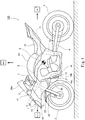
- Fig. 1 is a left side view of the motorcycle 100 according to the embodiment.
- the motorcycle 100 includes a vehicle body 1, the front wheel 2, a rear wheel 3, and the protruding sections 30 mounted to the the vehicle body 1 such that each of the protruding sections 30 protrudes from the vehicle body 1 to the right or to the left.
- the vehicle body 1 includes a vehicle body frame 4, a front cowling 20 covering the vehicle body frame 4 from forward, and the pair of right and left side cowlings 21 covering he front portion of the vehicle body frame 4 from laterally.
- the vehicle body frame 4 includes a head pipe 6, a pair of right and left main frames 8 extending rearward from the head pipe 6, a pair of right and left pivot frames 10 which extend continuously with the rear portions of the main frames 8, respectively, and to which the front end portions of a swing arm 9 are mounted such that the swing arm 9 is pivotable, and a pair of right and left seat rails 11 extending rearward from the pivot frames 10, respectively.
- the front cowling 20 is mounted to the front portion of the vehicle body frame 4 to cover the vehicle body 1 from forward.
- the right and left side cowlings 21 are placed behind and continuously with the front cowling 20.
- the side cowlings 21 are mounted to the front portion of the vehicle body frame 4 to cover the vehicle body 1 from laterally.
- the front cowling 20 and the side cowlings 21 have a streamline shape, and fair the air flowing along the vehicle body 1, to reduce an air resistance.
- a wind shield 20a is provided on the upper portion of the center of the front cowling 20.
- a head lamp 12 is attached to the front portion of the front cowling 20.
- a pair of right and left side mirrors 13 are attached to the side portion of the front cowling 20.
- the front wheel 2 is rotatably mounted to the lower end portions of front forks 5 extending substantially vertically.
- the front forks 5 are attached to a steering shaft (not shown) via an upper bracket (not shown) attached on upper end portions thereof.
- the front forks 5 are attached with a front fender 22 which covers the upper portion of the front wheel 2 from above.
- Fork guard sections 23 are placed forward relative to the front forks 5 to prevent entry of foreign matters into the front forks 5, respectively.
- the steering shaft (not shown) is rotatably supported by the head pipe 6.
- a bar-type steering handle 7 extending in the rightward and leftward direction is attached to the upper bracket.
- a fuel tank 14 is placed behind the steering handle 7 and fastened to the main frames 8.
- a riding seat 15 is mounted to the rear side of the fuel tank 14.
- the engine 16 is disposed between the front wheel 2 and the rear wheel 3 in a state in which the engine 16 is mounted to the main frames 8 and the pivot frames 10.
- the radiator 17 which is inclined forward is disposed behind the front wheel 2 and obliquely above the engine 16.
- the engine 16 has a cooling structure which causes cooling water to be circulated between the radiator 17 and a water jacket (not shown) so that heat is radiated from the cooling water in the radiator 17.
- the radiator 17 is covered with the side cowlings 21 which serves as shrouds.
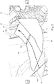
- Fig. 2 is a front view of the motorcycle of Fig. 1 .
- the side cowlings 21 are placed at the right and left sides of the front cowling 20, respectively, and a cowling 19 including the front cowling 20 and the side cowlings 21 entirely has an inverted-recess shape when viewed from forward.
- the cowling 19 has the opening 19a at a front side thereof, in a location that is forward relative to the radiator 17.
- the cowling 19 is configured to cover the front space of the radiator 17 from outward in the vehicle width direction and guide the air flowing from forward to the radiator 17. With the air flowing through the radiator 17, the radiator 17 cools the cooling water of the engine 16.
- the cowling 19 has a discharge outlet 19b at a rear side thereof, to discharge the air which has flowed through the radiator 17 (see Fig. 1 ).
- the motorcycle 100 includes the protruding sections 30 mounted to the vehicle body 1 such that they protrude from the vehicle body 1 to the right and to the left, respectively.
- the protruding sections 30 are disposed forward relative to a center of gravity A of the vehicle body 1.
- the protruding sections 30 are placed at the side cowlings 21 mounted to the side surfaces of the vehicle body 1, respectively.
- the protruding sections 30 protrude from the side cowlings 21, respectively, in a location that is forward relative to the engine 16. Therefore, the protruding sections 30 do not contact the knees of the rider straddling the vehicle body 1 and therefore do not affect the the rider's operation.
- the protruding sections 30 are mounted to the right and left side cowlings 21 such that they are laterally symmetric in the rightward and leftward direction.
- the right and left protruding sections 30 are equal in weight. Therefore, the protruding sections 30 do not affect the balance of the vehicle body 1 during driving of the motorcycle 100.
- the protruding sections 30 are positioned below the head lamp 12 attached to the front portion of the front cowling 20.
- the protruding sections 30 are positioned below the upper edge of the opening 19a of the cowling 19 (i.e., lower edge of the front cowling 20).
- the motorcycle 100 includes front guide members which are placed distant from the side cowlings 21, respectively, and forward relative to the protruding sections 30 to guide the air outward in the vehicle width direction.
- the front guide members used are fork guard sections 23 which are placed forward relative to the front forks 5, respectively to prevent entry of foreign matters into the front forks 5.
- the fork guard sections 23 are secured to the axle support member of the front wheel 2 together with the front fender 22.
- Each of the fork guard sections 23 has an inclined surface extending outward in the vehicle width direction, from its front end to its rear side and covering the front fork 5 from forward to guide the air flowing toward the front fork 5 outward in the vehicle width direction.
- the protruding sections 30 are placed between the upper and lower ends of the front fender 22 in a vertical direction.
- the front guide members may be the front fender 22 located at the upper portion of the front wheel 2.
- the protruding sections 30 When viewed from forward, the protruding sections 30 are located outward in the rightward and leftward direction, relative to the opening 19a located forward relative to the radiator 17 and between the upper and lower ends of the opening 19a in the vertical direction.
- the protruding sections 30 are mounted to the side cowlings 21, respectively, extending in a substantially vertical direction and in the forward and rearward direction, of the cowling 19.
- the front guide members preferably include portions which are placed inward in the vehicle width direction relative to the protruding sections 30 and are located as high as the protruding sections 30 when viewed from forward.
- Fig. 3 is a perspective view of the protruding section 30 at the left side of the motorcycle of Fig. 2 .
- the protruding section 30 has a blade shape (plate shape) having upper and lower surfaces.
- the protruding section 30 will described as a blade device 30.
- the blade device 30 includes a front blade 31 protruding laterally from the side cowling 21, a rear blade 32 protruding laterally from the side cowling 21 in a location that is behind the front blade 31, and a guide wall 33 protruding downward from the outer end portion of the front blade 31 in the vehicle width direction and the outer end portion of the rear blade 32 in the vehicle width direction.
- the blade device 30 is placed forward relative to the center of gravity A of the vehicle body. Therefore, the grounding force of the front wheel 2 on the road surface can be improved, and reduction of the grounding force of the front wheel 2 on the road surface can be prevented during high-speed driving of the motorcycle 100.
- the front blade 31, the rear blade 32, and the guide wall 33 are covered with resin, and have a smooth shape which allows the air to easily flow along them.
- the side cowling 21 has a recess 21c which is provided on the outer side surface thereof and recessed inward in the vehicle width direction. As will be described later with reference to Fig. 6 , the inner end portion of the front blade 31 in the vehicle width direction is inserted into the recess 21c.
- the engine 16 and surrounding components are placed rearward relative to the discharge outlet 19b of the cowling 19. Since the surfaces of the engine 16 and of the components are not aligned, the flow of discharged air is disordered. To avoid this, a most part of the blade device 30 is placed forward relative to the discharge outlet 19b of the cowling 19. The rear end portion of the rear blade 32 is located rearward relative to the discharge outlet 19b of the cowling 19. In other words, the rear end portion of the blade device 30 protrudes rearward farther than the cowling 19. In this structure, the air which flows through the outward region of the cowling 19 and is less disordered can be utilized to improve the grounding force on the road surface, rather than the air discharged from the discharge outlet 19b, while reducing the number of components for fairing the air flow.
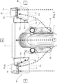
- Fig. 4 is a front view of the blade device 30 of Fig. 3 .
- the guide wall 33 protrudes downward from the outer end portion of the front blade 31 in the vehicle width direction and the outer end portion of the rear blade 32 in the vehicle width direction.
- the lower edge 33a of the guide wall 33 is curved inward in the vehicle width direction (toward the side cowling 21).
- the side cowling 21 and the guide wall 33 serve as a pair of blade end plates located at the right and left ends of the front blade 31 and of the rear blade 32, respectively.
- the outer side surface of the side cowling 21 and the inner side surface of the guide wall 33 are able to capture the air flowing along the lower surfaces of the blades 31, 32 (direction from an obverse side toward a reverse side of the sheet of Fig. 4 ) to prevent the air from escaping from the lower surfaces of the blades 31, 32. In this way, the down force can be efficiently produced.
- Fig. 5 is a cross-sectional view of the blade device 30 of the motorcycle of Fig. 4 , taken along line of V-V of Fig. 4 .
- each of the front blade 31 and the rear blade 32 has a cross-section of a substantially blade shape in which its front edge is curved and its rear edge is sharp as compared to the front edge.
- Each of the front blade 31 and the rear blade 32 has a cross-section in which the length of the lower surface in the forward and rearward direction is larger than the length of the upper surface in the forward and rearward direction.
- Each of the front blade 31 and the rear blade 32 is designed so that the air flows along the upper and lower surfaces (as indicated by dotted-line arrows of Fig.
- each of the front blade 31 and the rear blade 32 is designed so that the shape of a wing for generating a lift is reversed in the vertical direction. With this shape, the down force for pushing the vehicle body 1 downward can be produced by utilizing a pressure difference between the upper and lower sides of each of the blades 31, 32. Since the vehicle body 1 is pushed downward, the front wheel 2 is pushed on the road surface and the grounding force of the front wheel 2 on the road surface can be improved.
- the front blade 31 and the rear blade 32 are arranged at the front and at the rear, respectively such that a gap G is formed between them in the travelling direction of the motorcycle 100.
- a portion of the air which has flowed along the upper surface of the front blade 31 flows through the gap G and joins the air flowing along the lower surface of the rear blade 32.
- the front end portion of the rear blade 32 is located above the rear end portion of the front blade 31, and therefore the front end portion of the rear blade 32 overlaps with the rear end portion of the front blade 31, when viewed from a side. This allows a portion of the air which has flowed along the upper surface of the front blade 31 to be easily guided to the lower surface of the rear blade 32 through the gap G.
- the velocity of the air flowing along the lower surface of the rear blade 32 can be easily made higher than that of the air flowing along the upper surface of the rear blade 32.
- the gap G is not provided between the front and rear blades, it becomes possible to efficiently generate the down force while preventing an excess increase in the width or length of the blade.
- the width of the blades can be reduced, and thus the effects of the blades on the rider's operation can be avoided.
- the protruding length of the blade can be reduced, and the bank angle of the vehicle body 1 can be made sufficiently large.
- the upper surface of the blade device 30 is an inclined surface which is inclined upward as it extends rearward.
- the upper surface of the rear blade 32 is inclined upward as it extends rearward.
- the rear end of the rear blade 32 is located above the front end of the rear blade 32.
- the counteraction of a force generated when the air flows from forward to rearward along the upper surface of the rear blade 32 and is deflected, generates a force for pushing the upper surface of the rear blade 32 downward.
- the upper surface of the blade device 30 forms an angle of attack with respect to the travelling direction of the motorcycle 100 as it extends rearward, and the down force can be further increased by utilizing a push-down force caused by this angle of attack.
- the inclination angle of a virtual line connecting the front end of the front blade 31 to the rear end of the front blade 31, with respect to a horizontal line is smaller than the inclination angle of a virtual line connecting the front end of the rear blade 32 to the rear end of the rear blade 32, with respect to the horizontal line.
- the front blade 31 includes a core metal 31c which is made of metal and has a flat plate shape, a lower member 31a which is made of resin and covers the lower side of the core metal 31c, and an upper member 31b which is made of resin and covers the upper side of the core metal 31c.
- the core metal 31c, the lower member 31a, and the upper member 31b of the front blade 31 are fastened to each other by using screws S from below.
- the rear blade 32 includes a core metal 32a which is made of metal, and a blade body 32b which is made of resin and covers the core metal 32a.
- the core metal 32a constitutes a portion of the lower surface of the rear blade 32.
- the core metal 32a and the blade body 32b of the rear blade 32 are fastened to each other by using screws S from below.
- Fig. 6 is a plan view of the blade devices 30 of the motorcycle 100 of Fig. 4 .
- the pair of right and left side cowlings 21 are mounted to the end portions of the support member (not shown) extending in the vehicle width direction, respectively.
- the air (dotted-line arrows of Fig. 6 ) flowing from forward toward the vehicle body 1 of the motorcycle 100 is introduced into the opening 19a of the cowling 19, guided outward in the vehicle width direction along the right and left fork guard sections 23 covering the lower portions of the front forks 5, and faired by the outer side surfaces of the side cowlings 21.
- the blade devices 30 are mounted to the side cowlings 21, respectively, the air flow which is less disordered can be utilized in the blade devices 30.
- the side cowlings 21 can prevent the air flowing along the blade devices 30 from flowing inward in the vehicle width direction.
- each of the blade devices 30 is located in the rear portion of a region of the corresponding side cowling 21, which region swells outward in the vehicle width direction, from the front portion of the side cowling 21 toward the rear portion of the side cowling 21.
- the front blade 31 of the blade device 30 has a shape in which its width increases as it extends forward, when viewed from above. With the above configuration, the air can be guided with a large quantity to the blade device 30.
- the right and left front blades 31 are mounted to the side cowlings 21, respectively in such a manner that the inner ends in the vehicle width direction are inserted into the recesses 21c provided on the outer side surfaces of the side cowlings 21, respectively and extending in the forward and rearward direction.
- the inner end portions of the right and left blade devices 30 applied with the down force can be stably supported by the recesses 21c of the side cowlings 21, respectively.
- a plurality of stud bolts 31d are attached to the inner end portion of the core metal 31c of each of the front blades 31, in the vehicle width direction.
- the tip ends of these stud bolts 31d are inserted into holes of the recess 21c of the corresponding side cowling 21 and fastened by nuts, respectively, on the inner side of the side cowling 21.
- the blade device 30 is supported by the recess 21c of the side cowling 21 and fastened to the side cowling 21 by using the stud bolts 31d. Therefore, the blade device 30 is able to withstand a vertical force generated on the upper and lower surfaces of the blades.
- Each of the right and left rear blades 32 (dotted lines of Fig. 6 ) has a stud bolt 32c protruding inward in the vehicle width direction, of the core metal 32a of the rear blade 32.
- the stud bolt 32c penetrates the front end portion of the core metal 32a and is fastened to the core metal 32a.
- the stud bolt 32c is also inserted into the hole of the recess 21c of the side cowling 21 and fastened by the nut on the inner side of the side cowling 21.
- Fig. 7 is a bottom view of the blade device 30 of the motorcycle of Fig. 4 .
- the core metal 31c, the lower member 31a and the upper member 31b of the front blade 31 are fastened to each other in plural locations by using the screws S from below.
- the core metal 32a and the blade body 32b of the rear blade 32 are fastened to each other in plural locations by using the screws S from below.
- the lower edge 33a of the guide wall 33 is curved inward (toward the side cowling 21) as it extends rearward.
- the width of each of the blades 31, 32 decreases as it extends rearward, whereas the lower edge 33a of the guide wall 33 protrudes with a larger amount as it extends rearward.
- the air (see dotted-line arrows of Fig. 7 ) can be guided with a large quantity, while the air guided along the guide wall 33 is throttled. Because of Venturi effect, the velocity of the air flow along the lower surfaces of the blades 31, 32 can be increased. In this way, an effective down force can be produced.
- the protruding section 30 is located between the upper and lower ends of the radiator 17 in the vertical direction and overlaps with the radiator 17, when viewed from a side (see Fig. 1 ).
- the vehicle body 1 is designed to form a path where the air which has flowed through the protruding section 30 joins the air which has flowed through the radiator 17. This facilitates the air flow through the radiator 17 (see Fig. 6 ).
- the vehicle body 1 may be designed so that the direction of the air which has flowed through the protruding section 30 and is deflected conforms to or is close to the direction that is perpendicular to the radiator 17.
- the protruding section 30 is placed below the front end of the front cowling 20. This makes it possible to prevent a situation in which the air flow disordered by the front cowling 20 is guided to the protruding section 30. Thus, the air flow which is less disordered can be guided to the protruding section 30.
- the protruding section 30 is placed below the upper end portion of the front wheel 2 (see Fig. 1 ).
- the blade device (protruding section) 30 includes stiff members (e.g., the core metal 31c and the stud bolt 31d of the blade 31) which are formed of a highly stiff material such as metal. These stiff members are fastened to the cowling 19 (e.g., the side cowling 21) or the cowl support member (e.g., the vehicle body frame 4). Since the blade device (protruding section) 30 is directly coupled to the cowling 19 (e.g., the side cowling 21) or the cowl support member (e.g., vehicle body frame 4), a vibration of the blade device 30 can be prevented.
- stiff members e.g., the core metal 31c and the stud bolt 31d of the blade 31
- the stiff members of the blade device (protruding section) 30 are covered with lightweight members (e.g., the lower member 31a and the upper member 31b of the front blade 31, and the rear blade body 32b) which are formed of a material which is lower in stiffness and smaller in weight than the stiff members. This allows the blade device 30 to reduce its weight while ensuring required support stiffness. If molded members are used as the lightweight members, a smooth surface shape can be easily formed.
- the blade device 30 can receive the air flowing from forward to rearward along the cowling 19, and the down force can be suitably produced as compared to a case where the blade device (protruding section) 30 is apart from the cowling 19 in the vehicle width direction.
- each of the front blade 31 and the rear blade 32 has a cross-section in which the length of the lower surface in the forward and rearward direction is larger than the length of the upper surface in the forward and rearward direction, a great pressure difference is generated between the upper and lower surfaces of each of the blades 31, 32, and the down force can be effectively produced.
- the blade having the cross-section in which the upper and lower sides are reversed with respect to the wing for generating a lift when viewed from the side a stable down force can be effectively produced.
- the right and left blade devices (protruding sections) 30 are mounted to the outer side surfaces of the side cowlings 21, respectively, the air flowing stably along the outer surfaces of the side cowlings 21 can be utilized in the blade device 30. Thus, the down force can be effectively generated by the blades.
- the side cowlings 21 have the recesses on the outer side surfaces, respectively, and the right and left blade devices (protruding sections) 30 are mounted to the side cowlings 21, respectively in such a manner that the inner end portions of the right and left blade devices (protruding sections) 30 in the vehicle width direction are inserted into the recesses 21c, respectively. Therefore, the inner end portions of the right and left blade devices 30 applied with the down force can be stably supported by the recesses 21c of the side cowlings 21, respectively.
- the protruding sections 30 are provided at the right and left sides, respectively, the protruding section 30 may be provided at only one of the right and left sides. If the weight of a portion of the vehicle body 1 which is at one of the right and left sides in the vehicle width direction, except for the protruding section 30, is larger than that of a portion of the vehicle body 1 which is at the other side in the vehicle width direction, the weight of the protruding section 30 at the other side may be made larger than that of the protruding section 30 at one side, to keep the balance of the vehicle body 1 in the vehicle width direction.
- the down force may be produced by utilizing a pressure difference in the air flow between the upper and lower surfaces of the front blade 31 and of the rear blade 32. Or, the down force may be produced in such a manner that the air flow colliding with the front blade 31 and the rear blade 32 causes a force for pushing the front blade 31 and the rear blade 32 downward.
- the protruding sections 30 are mounted to the side cowlings 21 attached to the side surfaces of the vehicle body 1, the present invention is not limited to this.
- the protruding sections 30 may be mounted to the side surfaces of the vehicle body frame 4.
- the blade devices 30 are fastened to the side cowlings 21, respectively, the present invention is not limited to this.
- the blade devices 30 may be removably mounted to the side cowlings 21, respectively, as necessary. If the blade devices 30 are removably mounted to the cowling 19, convenience can be improved. Also, if the blade device (protruding section) 30 is damaged (broken), it can be repaired without a need to replace the cowling 19. Or, in a case where plural kinds of blade devices 30 are prepared, the blade devices 30 according to the rider's preference may be used. Or, in a case where the blade devices 30 are not mounted to the side cowlings 21, respectively, the recesses 21c of the side cowlings 21 may be closed by plate members which are similar in color to the side cowlings 21, respectively.
- the blades 31, 32 may entirely have an angle of attack, or only the rear portions of the blades 31, 32 may have an angle of attack.
- the locations of the blade devices 30 are not particularly limited so long as the blade devices 30 are mounted to the sides of the vehicle body 1.
- the blade devices 30 may be located rearward relative to the riding seat 15, or the opening 19a of the cowling 19.
- the front and rear blades 31, 32 are fastened with a predetermined angle with respect to the travelling direction of the motorcycle 100
- the front blade 31 or the rear blade 32 may be movable.
- the inclination angle of the blades with respect to the travelling direction of the motorcycle 100 may be changeable.
- the blades are configured such that the metal plates are covered with resin
- the blades may be entirely formed of FRP (fiber reinforced plastic).
- the metal plate and the resin of each of the blades may be integrated by using FRP.
- the present invention is effectively applicable to a motorcycle including a cowling of a streamline shape which fairs air flowing from forward and along a vehicle body.
Landscapes
- Engineering & Computer Science (AREA)
- Mechanical Engineering (AREA)
- Chemical & Material Sciences (AREA)
- Combustion & Propulsion (AREA)
- Transportation (AREA)
- Automatic Cycles, And Cycles In General (AREA)
- Body Structure For Vehicles (AREA)
Claims (14)
- Moto (100) comprenant :une carrosserie (1) ;un carénage (19) installé sur une surface latérale de la carrosserie (1) ; etune section saillante (30) qui est installée sur le carénage (19) de telle sorte que la section saillante fasse saillie à partir de la carrosserie (1) vers la droite et/ou la gauche,la section saillante (30) présentant ainsi une structure qui amène l'air à s'écouler de l'avant vers l'arrière le long d'une surface supérieure de la section saillante afin de générer une force servant à pousser la carrosserie (1) vers le bas, etla section saillante (30) comprenant une paroi de guidage (33) qui fait saillie vers le bas à partir d'une partie d'extrémité extérieure de la section saillante (30) dans une direction de largeur du véhicule et est disposée à l'extérieur, dans la direction de largeur du véhicule, par rapport au carénage (19),caractérisée en ce queun bord inférieur (33a) de la paroi de guidage (33) est incurvé vers l'intérieur dans la direction de largeur du véhicule.
- Moto (100) selon la revendication 1,
dans laquelle une partie de la section saillante (30) est située dans une partie arrière d'une région du carénage (19), ladite région étant bombée vers l'extérieur dans la direction de largeur du véhicule, depuis une partie avant du carénage en direction d'une partie arrière du carénage. - Moto (100) selon la revendication 1 ou 2, comprenant en outre :un radiateur (17) placé en arrière par rapport à une roue avant (2),dans laquelle le carénage (19a) comporte une ouverture qui est située en avant par rapport au radiateur (17), recouvre le radiateur (17) depuis l'extérieur dans la direction de largeur, guide l'air vers le radiateur (17), et comporte une sortie de rejet (19b) à travers laquelle l'air qui s'est écoulé à travers le radiateur (17) est rejeté, etdans laquelle la section saillante (30) est placée en avant par rapport à la sortie de rejet (19b), et située entre des extrémités supérieure et inférieure du radiateur (17) dans une direction verticale.
- Moto (100) selon l'une quelconque des revendications 1 à 3,
dans laquelle une partie d'extrémité avant de la section saillante (30) présente une forme dans laquelle sa largeur augmente à mesure que la section saillante s'étend vers l'avant, en regardant depuis le dessus. - Moto (100) selon l'une quelconque des revendications 1 à 4,
dans laquelle une partie d'extrémité inférieure de la paroi de guidage (33) est incurvée vers l'intérieur dans la direction de largeur du véhicule. - Moto (100) selon l'une quelconque des revendications 1 à 5, comprenant en outre :un élément de guidage avant (23) qui est placé en avant par rapport au carénage (19) pourvu de la section saillante (30) pour guider l'air vers l'extérieur dans la direction de largeur du véhicule,dans laquelle la section saillante (30) est située entre des extrémités supérieure et inférieure de l'élément de guidage avant (23) dans une direction verticale.
- Moto (100) selon l'une quelconque des revendications 1 à 6,
dans laquelle la section saillante (30) peut être divisée en une section saillante avant (31) et une section saillante arrière (32), et
dans laquelle la section saillante avant (31) et la section saillante arrière (32) sont respectivement disposées au niveau d'un côté avant et d'un côté arrière, de telle sorte qu'il y ait un espace (G) entre la section saillante avant et la section saillante arrière dans une direction d'avance de la moto. - Moto (100) selon l'une quelconque des revendications 1 à 7,
dans laquelle la surface supérieure de la section saillante (30) est inclinée vers le haut à mesure que la surface supérieure s'étend vers l'arrière. - Moto (100) selon l'une quelconque des revendications 1 à 8,
dans laquelle une partie de la section saillante (30) est située dans une région du carénage (19), ladite région étant bombée vers l'extérieur dans la direction de largeur du véhicule à mesure que le carénage (19) s'étend vers l'arrière, et
dans laquelle la partie de la section saillante (30) présente une largeur qui diminue à mesure que la partie s'étend vers l'arrière. - Moto selon la revendication 1 ou 2, comprenant :un radiateur (17) placé en arrière par rapport à une roue avant (2),dans laquelle le carénage (19) comporte une ouverture qui est située en avant par rapport au radiateur (17),recouvre l'espace avant du radiateur (17) depuis l'extérieur dans la direction de largeur du véhicule, et guide l'air vers le radiateur (17), etdans laquelle la section saillante (30) est située entre des extrémités supérieure et inférieure du radiateur (17) dans une direction verticale.
- Moto (100) selon la revendication 1,
dans laquelle la section saillante (30) comprend une lame avant (31) et une lame arrière (32), et
dans laquelle chacune des lames (31, 32) présente une largeur diminuant à mesure que chacune des lames (31, 32) s'étend vers l'arrière, et le bord inférieur (33a) de la paroi de guidage (33) fait saillie de manière croissante à mesure que le bord inférieur (33a) s'étend vers l'arrière. - Moto (100) selon la revendication 1,
dans laquelle le carénage (19) comprend un carénage latéral (21), et
dans laquelle la section saillante (30) est installée de manière amovible sur le carénage latéral (21). - Moto (100) selon la revendication 12,
dans laquelle la section saillante (30) comprend une lame avant (31), et
dans laquelle la lame avant (31) comprend un métal d'âme (31c) qui est composé de métal et présente une forme de plaque plane, un élément inférieur (31a) qui est composé de résine et recouvre un côté inférieur du métal d'âme (31c), et un élément supérieur (31b) qui est composé de résine et recouvre un côté supérieur du métal d'âme (31c). - Moto (100) selon la revendication 1,
dans laquelle la section saillante (30) est située en arrière par rapport à une ouverture (19a) du carénage (19).
Applications Claiming Priority (1)
| Application Number | Priority Date | Filing Date | Title |
|---|---|---|---|
| PCT/JP2013/006730 WO2015071934A1 (fr) | 2013-11-15 | 2013-11-15 | Moto |
Publications (3)
| Publication Number | Publication Date |
|---|---|
| EP3069971A1 EP3069971A1 (fr) | 2016-09-21 |
| EP3069971A4 EP3069971A4 (fr) | 2017-07-05 |
| EP3069971B1 true EP3069971B1 (fr) | 2018-10-17 |
Family
ID=53056905
Family Applications (1)
| Application Number | Title | Priority Date | Filing Date |
|---|---|---|---|
| EP13897448.0A Active EP3069971B1 (fr) | 2013-11-15 | 2013-11-15 | Moto |
Country Status (4)
| Country | Link |
|---|---|
| US (1) | US9573645B2 (fr) |
| EP (1) | EP3069971B1 (fr) |
| CN (1) | CN105377681A (fr) |
| WO (1) | WO2015071934A1 (fr) |
Families Citing this family (13)
| Publication number | Priority date | Publication date | Assignee | Title |
|---|---|---|---|---|
| EP3072791B1 (fr) * | 2013-11-15 | 2020-01-08 | Kawasaki Jukogyo Kabushiki Kaisha | Véhicule de type à enfourcher |
| DE102014222297A1 (de) * | 2014-10-31 | 2016-05-04 | Bayerische Motoren Werke Aktiengesellschaft | Einspuriges motorbetriebenes Kraftfahrzeug mit mittragender Verkleidung |
| JP6129884B2 (ja) * | 2015-01-23 | 2017-05-17 | 本田技研工業株式会社 | 鞍乗り型車両のサイドカバー構造 |
| JP6224664B2 (ja) * | 2015-09-08 | 2017-11-01 | 本田技研工業株式会社 | 鞍乗り型車両 |
| JP6555074B2 (ja) * | 2015-10-27 | 2019-08-07 | スズキ株式会社 | 電動二輪車用の電力変換装置の冷却構造 |
| JP6536351B2 (ja) * | 2015-10-27 | 2019-07-03 | スズキ株式会社 | 電動二輪車のスイングアーム |
| JP6679535B2 (ja) * | 2017-05-31 | 2020-04-15 | 本田技研工業株式会社 | 鞍乗り型車両 |
| JP6663949B2 (ja) | 2018-03-30 | 2020-03-13 | 本田技研工業株式会社 | 鞍乗型車両 |
| JP6663451B2 (ja) | 2018-04-26 | 2020-03-11 | 本田技研工業株式会社 | 鞍乗型車両 |
| IT201800010029A1 (it) * | 2018-11-05 | 2020-05-05 | Piaggio & C Spa | Dispositivo aerodinamico attivo per motoveicoli e relativo motoveicolo |
| IT201800010889A1 (it) | 2018-12-07 | 2020-06-07 | Piaggio & C Spa | Avantreno di motociclo con raffreddamento migliorato e relativo motociclo |
| JP6855514B2 (ja) * | 2019-01-18 | 2021-04-07 | 本田技研工業株式会社 | 鞍乗り型車両 |
| JP2022069340A (ja) * | 2020-10-23 | 2022-05-11 | カワサキモータース株式会社 | 鞍乗型車両 |
Family Cites Families (22)
| Publication number | Priority date | Publication date | Assignee | Title |
|---|---|---|---|---|
| IT1014079B (it) * | 1974-05-02 | 1977-04-20 | Morelli A | Dispositivo aerodinamico per migliorare le condizioni di marcia ad alta velocita dei motoveicoli |
| JPS6057481U (ja) * | 1983-09-02 | 1985-04-22 | 本田技研工業株式会社 | 車輌のスタビライザ |
| JPH0327028Y2 (fr) | 1986-05-02 | 1991-06-11 | ||
| US4887688A (en) * | 1987-08-06 | 1989-12-19 | Honda Giken Kogyo Kabushiki Kaisha | Motorcycle |
| JPH05170157A (ja) | 1991-12-24 | 1993-07-09 | Suzuki Motor Corp | 自動二輪車のスタビライザ装置 |
| JPH0657481U (ja) | 1993-01-08 | 1994-08-09 | 俊一 川又 | 小便処理装置 |
| JPH09240540A (ja) | 1996-03-06 | 1997-09-16 | Honda Motor Co Ltd | 自動二輪車における前輪接地圧増強装置 |
| JP3373153B2 (ja) | 1998-06-03 | 2003-02-04 | 川崎重工業株式会社 | 自動二輪車の抵抗抑制装置 |
| JP3889236B2 (ja) * | 2001-04-04 | 2007-03-07 | 本田技研工業株式会社 | 自動二輪車の排気系構造 |
| JP2005088641A (ja) | 2003-09-12 | 2005-04-07 | Kawasaki Heavy Ind Ltd | 自動二輪車の整流機構 |
| JP4531613B2 (ja) * | 2005-03-31 | 2010-08-25 | 本田技研工業株式会社 | 車輌のカウル構造 |
| JP4425821B2 (ja) * | 2005-03-31 | 2010-03-03 | 本田技研工業株式会社 | 収納ボックス構造 |
| JP4397877B2 (ja) * | 2005-10-31 | 2010-01-13 | 本田技研工業株式会社 | 車両のハザード保持機能付きウインカ装置 |
| US20070256882A1 (en) * | 2006-05-05 | 2007-11-08 | Bombardier Recreational Products Inc. | Three-Wheel Vehicle |
| TWI394679B (zh) * | 2007-02-06 | 2013-05-01 | Honda Motor Co Ltd | Windshield device |
| JP5020653B2 (ja) * | 2007-02-06 | 2012-09-05 | 本田技研工業株式会社 | 風防装置 |
| US8104936B2 (en) * | 2007-09-18 | 2012-01-31 | Yamaha Hatsudoki Kabushiki Kaisha | Straddle-type vehicle |
| JP5339600B2 (ja) | 2009-03-26 | 2013-11-13 | 本田技研工業株式会社 | 自動二輪車 |
| JP5486978B2 (ja) * | 2010-03-25 | 2014-05-07 | 本田技研工業株式会社 | 自動二輪車のカウル構造 |
| DE102011110183B3 (de) | 2011-08-09 | 2012-11-15 | Pilz Gmbh & Co. Kg | Modulare Steuerungsvorrichtung |
| JP5941810B2 (ja) * | 2012-09-28 | 2016-06-29 | 本田技研工業株式会社 | 鞍乗型車両のフロントカウル構造 |
| JP5894898B2 (ja) * | 2012-09-28 | 2016-03-30 | 本田技研工業株式会社 | 鞍乗型車両のフロントカウル構造 |
-
2013
- 2013-11-15 CN CN201380078403.1A patent/CN105377681A/zh active Pending
- 2013-11-15 WO PCT/JP2013/006730 patent/WO2015071934A1/fr active Application Filing
- 2013-11-15 US US14/769,521 patent/US9573645B2/en active Active
- 2013-11-15 EP EP13897448.0A patent/EP3069971B1/fr active Active
Non-Patent Citations (1)
| Title |
|---|
| None * |
Also Published As
| Publication number | Publication date |
|---|---|
| EP3069971A1 (fr) | 2016-09-21 |
| WO2015071934A1 (fr) | 2015-05-21 |
| EP3069971A4 (fr) | 2017-07-05 |
| US9573645B2 (en) | 2017-02-21 |
| CN105377681A (zh) | 2016-03-02 |
| US20160016623A1 (en) | 2016-01-21 |
Similar Documents
| Publication | Publication Date | Title |
|---|---|---|
| EP3069971B1 (fr) | Moto | |
| CN102133910B (zh) | 骑跨型车辆的罩结构 | |
| US7448461B2 (en) | Cowl structure of vehicle | |
| JP5129712B2 (ja) | 自動二輪車のラジエータ取付け構造 | |
| US20090008182A1 (en) | Radiator coil mounted on a motorcycle | |
| CN109424417B (zh) | 骑乘型车辆及散热器导风装置 | |
| US9834266B2 (en) | Body cover for straddle type vehicle, and straddle type vehicle including same | |
| JP6411178B2 (ja) | 自動二輪車 | |
| JP6254511B2 (ja) | 鞍乗り型車両のフロントフェンダー | |
| EP2628671A1 (fr) | Véhicule du type à selle | |
| EP2075179B1 (fr) | Motocyclette | |
| EP2161187A1 (fr) | Motocyclette | |
| US20160297492A1 (en) | Cowling structure of straddle-type vehicle and straddle-type vehicle | |
| EP2481657B1 (fr) | Véhicule à monture de selle | |
| JP5837777B2 (ja) | 鞍乗型車両 | |
| EP2460680A2 (fr) | Motocycle, véhicule et cache-radiateur | |
| EP3150480A1 (fr) | Véhicule à selle | |
| JP6467192B2 (ja) | 鞍乗型車両 | |
| JP6311441B2 (ja) | 自動二輪車のレクチファイア取付構造 | |
| EP3069980B1 (fr) | Structure d'agencement de radiateur pour des véhicules de type à selle | |
| JP5700676B2 (ja) | 鞍乗型車両の外装部品 | |
| US20100181131A1 (en) | Vehicle shroud | |
| EP3964435A1 (fr) | Volet de ventilation | |
| EP2712795B1 (fr) | Véhicule de type à enfourcher | |
| JP2009107553A (ja) | 鞍乗型車両 |
Legal Events
| Date | Code | Title | Description |
|---|---|---|---|
| PUAI | Public reference made under article 153(3) epc to a published international application that has entered the european phase |
Free format text: ORIGINAL CODE: 0009012 |
|
| 17P | Request for examination filed |
Effective date: 20151015 |
|
| AK | Designated contracting states |
Kind code of ref document: A1 Designated state(s): AL AT BE BG CH CY CZ DE DK EE ES FI FR GB GR HR HU IE IS IT LI LT LU LV MC MK MT NL NO PL PT RO RS SE SI SK SM TR |
|
| AX | Request for extension of the european patent |
Extension state: BA ME |
|
| DAX | Request for extension of the european patent (deleted) | ||
| A4 | Supplementary search report drawn up and despatched |
Effective date: 20170601 |
|
| RIC1 | Information provided on ipc code assigned before grant |
Ipc: B62J 99/00 20090101ALI20170526BHEP Ipc: B62J 17/00 20060101AFI20170526BHEP Ipc: B62J 23/00 20060101ALI20170526BHEP |
|
| GRAP | Despatch of communication of intention to grant a patent |
Free format text: ORIGINAL CODE: EPIDOSNIGR1 |
|
| INTG | Intention to grant announced |
Effective date: 20180430 |
|
| GRAS | Grant fee paid |
Free format text: ORIGINAL CODE: EPIDOSNIGR3 |
|
| GRAA | (expected) grant |
Free format text: ORIGINAL CODE: 0009210 |
|
| AK | Designated contracting states |
Kind code of ref document: B1 Designated state(s): AL AT BE BG CH CY CZ DE DK EE ES FI FR GB GR HR HU IE IS IT LI LT LU LV MC MK MT NL NO PL PT RO RS SE SI SK SM TR |
|
| REG | Reference to a national code |
Ref country code: GB Ref legal event code: FG4D |
|
| REG | Reference to a national code |
Ref country code: CH Ref legal event code: EP |
|
| REG | Reference to a national code |
Ref country code: IE Ref legal event code: FG4D |
|
| REG | Reference to a national code |
Ref country code: DE Ref legal event code: R096 Ref document number: 602013045411 Country of ref document: DE Ref country code: AT Ref legal event code: REF Ref document number: 1053663 Country of ref document: AT Kind code of ref document: T Effective date: 20181115 |
|
| REG | Reference to a national code |
Ref country code: NL Ref legal event code: MP Effective date: 20181017 |
|
| REG | Reference to a national code |
Ref country code: LT Ref legal event code: MG4D |
|
| REG | Reference to a national code |
Ref country code: AT Ref legal event code: MK05 Ref document number: 1053663 Country of ref document: AT Kind code of ref document: T Effective date: 20181017 |
|
| PG25 | Lapsed in a contracting state [announced via postgrant information from national office to epo] |
Ref country code: NL Free format text: LAPSE BECAUSE OF FAILURE TO SUBMIT A TRANSLATION OF THE DESCRIPTION OR TO PAY THE FEE WITHIN THE PRESCRIBED TIME-LIMIT Effective date: 20181017 |
|
| PG25 | Lapsed in a contracting state [announced via postgrant information from national office to epo] |
Ref country code: NO Free format text: LAPSE BECAUSE OF FAILURE TO SUBMIT A TRANSLATION OF THE DESCRIPTION OR TO PAY THE FEE WITHIN THE PRESCRIBED TIME-LIMIT Effective date: 20190117 Ref country code: BG Free format text: LAPSE BECAUSE OF FAILURE TO SUBMIT A TRANSLATION OF THE DESCRIPTION OR TO PAY THE FEE WITHIN THE PRESCRIBED TIME-LIMIT Effective date: 20190117 Ref country code: PL Free format text: LAPSE BECAUSE OF FAILURE TO SUBMIT A TRANSLATION OF THE DESCRIPTION OR TO PAY THE FEE WITHIN THE PRESCRIBED TIME-LIMIT Effective date: 20181017 Ref country code: HR Free format text: LAPSE BECAUSE OF FAILURE TO SUBMIT A TRANSLATION OF THE DESCRIPTION OR TO PAY THE FEE WITHIN THE PRESCRIBED TIME-LIMIT Effective date: 20181017 Ref country code: AT Free format text: LAPSE BECAUSE OF FAILURE TO SUBMIT A TRANSLATION OF THE DESCRIPTION OR TO PAY THE FEE WITHIN THE PRESCRIBED TIME-LIMIT Effective date: 20181017 Ref country code: LV Free format text: LAPSE BECAUSE OF FAILURE TO SUBMIT A TRANSLATION OF THE DESCRIPTION OR TO PAY THE FEE WITHIN THE PRESCRIBED TIME-LIMIT Effective date: 20181017 Ref country code: FI Free format text: LAPSE BECAUSE OF FAILURE TO SUBMIT A TRANSLATION OF THE DESCRIPTION OR TO PAY THE FEE WITHIN THE PRESCRIBED TIME-LIMIT Effective date: 20181017 Ref country code: IS Free format text: LAPSE BECAUSE OF FAILURE TO SUBMIT A TRANSLATION OF THE DESCRIPTION OR TO PAY THE FEE WITHIN THE PRESCRIBED TIME-LIMIT Effective date: 20190217 Ref country code: LT Free format text: LAPSE BECAUSE OF FAILURE TO SUBMIT A TRANSLATION OF THE DESCRIPTION OR TO PAY THE FEE WITHIN THE PRESCRIBED TIME-LIMIT Effective date: 20181017 Ref country code: ES Free format text: LAPSE BECAUSE OF FAILURE TO SUBMIT A TRANSLATION OF THE DESCRIPTION OR TO PAY THE FEE WITHIN THE PRESCRIBED TIME-LIMIT Effective date: 20181017 |
|
| PG25 | Lapsed in a contracting state [announced via postgrant information from national office to epo] |
Ref country code: GR Free format text: LAPSE BECAUSE OF FAILURE TO SUBMIT A TRANSLATION OF THE DESCRIPTION OR TO PAY THE FEE WITHIN THE PRESCRIBED TIME-LIMIT Effective date: 20190118 Ref country code: PT Free format text: LAPSE BECAUSE OF FAILURE TO SUBMIT A TRANSLATION OF THE DESCRIPTION OR TO PAY THE FEE WITHIN THE PRESCRIBED TIME-LIMIT Effective date: 20190217 Ref country code: SE Free format text: LAPSE BECAUSE OF FAILURE TO SUBMIT A TRANSLATION OF THE DESCRIPTION OR TO PAY THE FEE WITHIN THE PRESCRIBED TIME-LIMIT Effective date: 20181017 Ref country code: AL Free format text: LAPSE BECAUSE OF FAILURE TO SUBMIT A TRANSLATION OF THE DESCRIPTION OR TO PAY THE FEE WITHIN THE PRESCRIBED TIME-LIMIT Effective date: 20181017 Ref country code: RS Free format text: LAPSE BECAUSE OF FAILURE TO SUBMIT A TRANSLATION OF THE DESCRIPTION OR TO PAY THE FEE WITHIN THE PRESCRIBED TIME-LIMIT Effective date: 20181017 |
|
| REG | Reference to a national code |
Ref country code: CH Ref legal event code: PL |
|
| REG | Reference to a national code |
Ref country code: DE Ref legal event code: R097 Ref document number: 602013045411 Country of ref document: DE |
|
| PG25 | Lapsed in a contracting state [announced via postgrant information from national office to epo] |
Ref country code: CZ Free format text: LAPSE BECAUSE OF FAILURE TO SUBMIT A TRANSLATION OF THE DESCRIPTION OR TO PAY THE FEE WITHIN THE PRESCRIBED TIME-LIMIT Effective date: 20181017 Ref country code: LU Free format text: LAPSE BECAUSE OF NON-PAYMENT OF DUE FEES Effective date: 20181115 Ref country code: IT Free format text: LAPSE BECAUSE OF FAILURE TO SUBMIT A TRANSLATION OF THE DESCRIPTION OR TO PAY THE FEE WITHIN THE PRESCRIBED TIME-LIMIT Effective date: 20181017 Ref country code: DK Free format text: LAPSE BECAUSE OF FAILURE TO SUBMIT A TRANSLATION OF THE DESCRIPTION OR TO PAY THE FEE WITHIN THE PRESCRIBED TIME-LIMIT Effective date: 20181017 |
|
| REG | Reference to a national code |
Ref country code: BE Ref legal event code: MM Effective date: 20181130 |
|
| REG | Reference to a national code |
Ref country code: IE Ref legal event code: MM4A |
|
| PLBE | No opposition filed within time limit |
Free format text: ORIGINAL CODE: 0009261 |
|
| STAA | Information on the status of an ep patent application or granted ep patent |
Free format text: STATUS: NO OPPOSITION FILED WITHIN TIME LIMIT |
|
| PG25 | Lapsed in a contracting state [announced via postgrant information from national office to epo] |
Ref country code: MC Free format text: LAPSE BECAUSE OF FAILURE TO SUBMIT A TRANSLATION OF THE DESCRIPTION OR TO PAY THE FEE WITHIN THE PRESCRIBED TIME-LIMIT Effective date: 20181017 Ref country code: LI Free format text: LAPSE BECAUSE OF NON-PAYMENT OF DUE FEES Effective date: 20181130 Ref country code: CH Free format text: LAPSE BECAUSE OF NON-PAYMENT OF DUE FEES Effective date: 20181130 Ref country code: SM Free format text: LAPSE BECAUSE OF FAILURE TO SUBMIT A TRANSLATION OF THE DESCRIPTION OR TO PAY THE FEE WITHIN THE PRESCRIBED TIME-LIMIT Effective date: 20181017 Ref country code: EE Free format text: LAPSE BECAUSE OF FAILURE TO SUBMIT A TRANSLATION OF THE DESCRIPTION OR TO PAY THE FEE WITHIN THE PRESCRIBED TIME-LIMIT Effective date: 20181017 Ref country code: SK Free format text: LAPSE BECAUSE OF FAILURE TO SUBMIT A TRANSLATION OF THE DESCRIPTION OR TO PAY THE FEE WITHIN THE PRESCRIBED TIME-LIMIT Effective date: 20181017 Ref country code: RO Free format text: LAPSE BECAUSE OF FAILURE TO SUBMIT A TRANSLATION OF THE DESCRIPTION OR TO PAY THE FEE WITHIN THE PRESCRIBED TIME-LIMIT Effective date: 20181017 |
|
| 26N | No opposition filed |
Effective date: 20190718 |
|
| GBPC | Gb: european patent ceased through non-payment of renewal fee |
Effective date: 20190117 |
|
| PG25 | Lapsed in a contracting state [announced via postgrant information from national office to epo] |
Ref country code: IE Free format text: LAPSE BECAUSE OF NON-PAYMENT OF DUE FEES Effective date: 20181115 Ref country code: SI Free format text: LAPSE BECAUSE OF FAILURE TO SUBMIT A TRANSLATION OF THE DESCRIPTION OR TO PAY THE FEE WITHIN THE PRESCRIBED TIME-LIMIT Effective date: 20181017 |
|
| PG25 | Lapsed in a contracting state [announced via postgrant information from national office to epo] |
Ref country code: BE Free format text: LAPSE BECAUSE OF NON-PAYMENT OF DUE FEES Effective date: 20181130 |
|
| PG25 | Lapsed in a contracting state [announced via postgrant information from national office to epo] |
Ref country code: GB Free format text: LAPSE BECAUSE OF NON-PAYMENT OF DUE FEES Effective date: 20190117 |
|
| PG25 | Lapsed in a contracting state [announced via postgrant information from national office to epo] |
Ref country code: MT Free format text: LAPSE BECAUSE OF NON-PAYMENT OF DUE FEES Effective date: 20181115 |
|
| PG25 | Lapsed in a contracting state [announced via postgrant information from national office to epo] |
Ref country code: TR Free format text: LAPSE BECAUSE OF FAILURE TO SUBMIT A TRANSLATION OF THE DESCRIPTION OR TO PAY THE FEE WITHIN THE PRESCRIBED TIME-LIMIT Effective date: 20181017 |
|
| PG25 | Lapsed in a contracting state [announced via postgrant information from national office to epo] |
Ref country code: CY Free format text: LAPSE BECAUSE OF FAILURE TO SUBMIT A TRANSLATION OF THE DESCRIPTION OR TO PAY THE FEE WITHIN THE PRESCRIBED TIME-LIMIT Effective date: 20181017 Ref country code: HU Free format text: LAPSE BECAUSE OF FAILURE TO SUBMIT A TRANSLATION OF THE DESCRIPTION OR TO PAY THE FEE WITHIN THE PRESCRIBED TIME-LIMIT; INVALID AB INITIO Effective date: 20131115 Ref country code: MK Free format text: LAPSE BECAUSE OF NON-PAYMENT OF DUE FEES Effective date: 20181017 |
|
| PGFP | Annual fee paid to national office [announced via postgrant information from national office to epo] |
Ref country code: FR Payment date: 20201013 Year of fee payment: 8 |
|
| REG | Reference to a national code |
Ref country code: DE Ref legal event code: R081 Ref document number: 602013045411 Country of ref document: DE Owner name: KAWASAKI MOTORS, LTD., AKASHI-SHI, JP Free format text: FORMER OWNER: KAWASAKI JUKOGYO KABUSHIKI KAISHA, KOBE-SHI, HYOGO, JP |
|
| PG25 | Lapsed in a contracting state [announced via postgrant information from national office to epo] |
Ref country code: FR Free format text: LAPSE BECAUSE OF NON-PAYMENT OF DUE FEES Effective date: 20211130 |
|
| PGFP | Annual fee paid to national office [announced via postgrant information from national office to epo] |
Ref country code: DE Payment date: 20230929 Year of fee payment: 11 |