EP3068700B1 - Verfahren und anlage zur herstellung einer verpackung - Google Patents
Verfahren und anlage zur herstellung einer verpackung Download PDFInfo
- Publication number
- EP3068700B1 EP3068700B1 EP14798817.4A EP14798817A EP3068700B1 EP 3068700 B1 EP3068700 B1 EP 3068700B1 EP 14798817 A EP14798817 A EP 14798817A EP 3068700 B1 EP3068700 B1 EP 3068700B1
- Authority
- EP
- European Patent Office
- Prior art keywords
- rear wall
- station
- elastic element
- blank
- side walls
- Prior art date
- Legal status (The legal status is an assumption and is not a legal conclusion. Google has not performed a legal analysis and makes no representation as to the accuracy of the status listed.)
- Active
Links
- 238000000034 method Methods 0.000 title claims description 13
- 238000009434 installation Methods 0.000 title 1
- 238000004806 packaging method and process Methods 0.000 claims description 53
- 239000000463 material Substances 0.000 claims description 11
- 238000004519 manufacturing process Methods 0.000 claims description 7
- 238000011144 upstream manufacturing Methods 0.000 claims description 4
- 238000005452 bending Methods 0.000 description 15
- 230000002093 peripheral effect Effects 0.000 description 6
- 230000014759 maintenance of location Effects 0.000 description 4
- 239000002184 metal Substances 0.000 description 3
- 239000004816 latex Substances 0.000 description 2
- 229920000126 latex Polymers 0.000 description 2
- 238000004026 adhesive bonding Methods 0.000 description 1
- 238000009960 carding Methods 0.000 description 1
- 238000005520 cutting process Methods 0.000 description 1
- 238000001514 detection method Methods 0.000 description 1
- 239000013013 elastic material Substances 0.000 description 1
- 229920001971 elastomer Polymers 0.000 description 1
- 238000005429 filling process Methods 0.000 description 1
- 230000004048 modification Effects 0.000 description 1
- 238000012986 modification Methods 0.000 description 1
- 230000000452 restraining effect Effects 0.000 description 1
- 239000007787 solid Substances 0.000 description 1
- 238000003860 storage Methods 0.000 description 1
- 239000000758 substrate Substances 0.000 description 1
Images


Classifications
-
- B—PERFORMING OPERATIONS; TRANSPORTING
- B61—RAILWAYS
- B61D—BODY DETAILS OR KINDS OF RAILWAY VEHICLES
- B61D45/00—Means or devices for securing or supporting the cargo, including protection against shocks
- B61D45/007—Fixing containers
-
- B—PERFORMING OPERATIONS; TRANSPORTING
- B31—MAKING ARTICLES OF PAPER, CARDBOARD OR MATERIAL WORKED IN A MANNER ANALOGOUS TO PAPER; WORKING PAPER, CARDBOARD OR MATERIAL WORKED IN A MANNER ANALOGOUS TO PAPER
- B31B—MAKING CONTAINERS OF PAPER, CARDBOARD OR MATERIAL WORKED IN A MANNER ANALOGOUS TO PAPER
- B31B50/00—Making rigid or semi-rigid containers, e.g. boxes or cartons
- B31B50/26—Folding sheets, blanks or webs
- B31B50/44—Folding sheets, blanks or webs by plungers moving through folding dies
- B31B50/46—Folding sheets, blanks or webs by plungers moving through folding dies and interconnecting side walls
- B31B50/48—Folding sheets, blanks or webs by plungers moving through folding dies and interconnecting side walls by folding or tucking in locking flaps
-
- B—PERFORMING OPERATIONS; TRANSPORTING
- B61—RAILWAYS
- B61D—BODY DETAILS OR KINDS OF RAILWAY VEHICLES
- B61D9/00—Tipping wagons
- B61D9/04—Adaptations of rail vehicle elements to tipping wagons
- B61D9/08—Frames; Supporting or guiding means for the bodies
-
- B—PERFORMING OPERATIONS; TRANSPORTING
- B65—CONVEYING; PACKING; STORING; HANDLING THIN OR FILAMENTARY MATERIAL
- B65B—MACHINES, APPARATUS OR DEVICES FOR, OR METHODS OF, PACKAGING ARTICLES OR MATERIALS; UNPACKING
- B65B43/00—Forming, feeding, opening or setting-up containers or receptacles in association with packaging
- B65B43/08—Forming three-dimensional containers from sheet material
- B65B43/10—Forming three-dimensional containers from sheet material by folding the material
-
- B—PERFORMING OPERATIONS; TRANSPORTING
- B65—CONVEYING; PACKING; STORING; HANDLING THIN OR FILAMENTARY MATERIAL
- B65B—MACHINES, APPARATUS OR DEVICES FOR, OR METHODS OF, PACKAGING ARTICLES OR MATERIALS; UNPACKING
- B65B43/00—Forming, feeding, opening or setting-up containers or receptacles in association with packaging
- B65B43/26—Opening or distending bags; Opening, erecting, or setting-up boxes, cartons, or carton blanks
- B65B43/265—Opening, erecting or setting-up boxes, cartons or carton blanks
-
- B—PERFORMING OPERATIONS; TRANSPORTING
- B65—CONVEYING; PACKING; STORING; HANDLING THIN OR FILAMENTARY MATERIAL
- B65D—CONTAINERS FOR STORAGE OR TRANSPORT OF ARTICLES OR MATERIALS, e.g. BAGS, BARRELS, BOTTLES, BOXES, CANS, CARTONS, CRATES, DRUMS, JARS, TANKS, HOPPERS, FORWARDING CONTAINERS; ACCESSORIES, CLOSURES, OR FITTINGS THEREFOR; PACKAGING ELEMENTS; PACKAGES
- B65D5/00—Rigid or semi-rigid containers of polygonal cross-section, e.g. boxes, cartons or trays, formed by folding or erecting one or more blanks made of paper
- B65D5/20—Rigid or semi-rigid containers of polygonal cross-section, e.g. boxes, cartons or trays, formed by folding or erecting one or more blanks made of paper by folding-up portions connected to a central panel from all sides to form a container body, e.g. of tray-like form
- B65D5/22—Rigid or semi-rigid containers of polygonal cross-section, e.g. boxes, cartons or trays, formed by folding or erecting one or more blanks made of paper by folding-up portions connected to a central panel from all sides to form a container body, e.g. of tray-like form held erect by extensions of one or more sides being doubled-over to enclose extensions of adjacent sides
-
- B—PERFORMING OPERATIONS; TRANSPORTING
- B65—CONVEYING; PACKING; STORING; HANDLING THIN OR FILAMENTARY MATERIAL
- B65D—CONTAINERS FOR STORAGE OR TRANSPORT OF ARTICLES OR MATERIALS, e.g. BAGS, BARRELS, BOTTLES, BOXES, CANS, CARTONS, CRATES, DRUMS, JARS, TANKS, HOPPERS, FORWARDING CONTAINERS; ACCESSORIES, CLOSURES, OR FITTINGS THEREFOR; PACKAGING ELEMENTS; PACKAGES
- B65D5/00—Rigid or semi-rigid containers of polygonal cross-section, e.g. boxes, cartons or trays, formed by folding or erecting one or more blanks made of paper
- B65D5/42—Details of containers or of foldable or erectable container blanks
- B65D5/4279—Joints, seams, leakproof joints or corners, special connections between panels
- B65D5/4283—Connections formed by separate elements, e.g. clips, bands, straps
-
- B—PERFORMING OPERATIONS; TRANSPORTING
- B65—CONVEYING; PACKING; STORING; HANDLING THIN OR FILAMENTARY MATERIAL
- B65D—CONTAINERS FOR STORAGE OR TRANSPORT OF ARTICLES OR MATERIALS, e.g. BAGS, BARRELS, BOTTLES, BOXES, CANS, CARTONS, CRATES, DRUMS, JARS, TANKS, HOPPERS, FORWARDING CONTAINERS; ACCESSORIES, CLOSURES, OR FITTINGS THEREFOR; PACKAGING ELEMENTS; PACKAGES
- B65D5/00—Rigid or semi-rigid containers of polygonal cross-section, e.g. boxes, cartons or trays, formed by folding or erecting one or more blanks made of paper
- B65D5/42—Details of containers or of foldable or erectable container blanks
- B65D5/44—Integral, inserted or attached portions forming internal or external fittings
- B65D5/52—External stands or display elements for contents
-
- B—PERFORMING OPERATIONS; TRANSPORTING
- B65—CONVEYING; PACKING; STORING; HANDLING THIN OR FILAMENTARY MATERIAL
- B65D—CONTAINERS FOR STORAGE OR TRANSPORT OF ARTICLES OR MATERIALS, e.g. BAGS, BARRELS, BOTTLES, BOXES, CANS, CARTONS, CRATES, DRUMS, JARS, TANKS, HOPPERS, FORWARDING CONTAINERS; ACCESSORIES, CLOSURES, OR FITTINGS THEREFOR; PACKAGING ELEMENTS; PACKAGES
- B65D5/00—Rigid or semi-rigid containers of polygonal cross-section, e.g. boxes, cartons or trays, formed by folding or erecting one or more blanks made of paper
- B65D5/42—Details of containers or of foldable or erectable container blanks
- B65D5/72—Contents-dispensing means
- B65D5/724—Internal fittings facilitating the discharge of contents, e.g. guiding panels, movable bottoms or lifting strips
-
- B—PERFORMING OPERATIONS; TRANSPORTING
- B31—MAKING ARTICLES OF PAPER, CARDBOARD OR MATERIAL WORKED IN A MANNER ANALOGOUS TO PAPER; WORKING PAPER, CARDBOARD OR MATERIAL WORKED IN A MANNER ANALOGOUS TO PAPER
- B31B—MAKING CONTAINERS OF PAPER, CARDBOARD OR MATERIAL WORKED IN A MANNER ANALOGOUS TO PAPER
- B31B2100/00—Rigid or semi-rigid containers made by folding single-piece sheets, blanks or webs
- B31B2100/002—Rigid or semi-rigid containers made by folding single-piece sheets, blanks or webs characterised by the shape of the blank from which they are formed
- B31B2100/0024—Rigid or semi-rigid containers made by folding single-piece sheets, blanks or webs characterised by the shape of the blank from which they are formed having all side walls attached to the bottom
-
- B—PERFORMING OPERATIONS; TRANSPORTING
- B31—MAKING ARTICLES OF PAPER, CARDBOARD OR MATERIAL WORKED IN A MANNER ANALOGOUS TO PAPER; WORKING PAPER, CARDBOARD OR MATERIAL WORKED IN A MANNER ANALOGOUS TO PAPER
- B31B—MAKING CONTAINERS OF PAPER, CARDBOARD OR MATERIAL WORKED IN A MANNER ANALOGOUS TO PAPER
- B31B2110/00—Shape of rigid or semi-rigid containers
- B31B2110/30—Shape of rigid or semi-rigid containers having a polygonal cross section
- B31B2110/35—Shape of rigid or semi-rigid containers having a polygonal cross section rectangular, e.g. square
-
- B—PERFORMING OPERATIONS; TRANSPORTING
- B31—MAKING ARTICLES OF PAPER, CARDBOARD OR MATERIAL WORKED IN A MANNER ANALOGOUS TO PAPER; WORKING PAPER, CARDBOARD OR MATERIAL WORKED IN A MANNER ANALOGOUS TO PAPER
- B31B—MAKING CONTAINERS OF PAPER, CARDBOARD OR MATERIAL WORKED IN A MANNER ANALOGOUS TO PAPER
- B31B50/00—Making rigid or semi-rigid containers, e.g. boxes or cartons
- B31B50/26—Folding sheets, blanks or webs
- B31B50/52—Folding sheets, blanks or webs by reciprocating or oscillating members, e.g. fingers
-
- B—PERFORMING OPERATIONS; TRANSPORTING
- B31—MAKING ARTICLES OF PAPER, CARDBOARD OR MATERIAL WORKED IN A MANNER ANALOGOUS TO PAPER; WORKING PAPER, CARDBOARD OR MATERIAL WORKED IN A MANNER ANALOGOUS TO PAPER
- B31B—MAKING CONTAINERS OF PAPER, CARDBOARD OR MATERIAL WORKED IN A MANNER ANALOGOUS TO PAPER
- B31B50/00—Making rigid or semi-rigid containers, e.g. boxes or cartons
- B31B50/74—Auxiliary operations
- B31B50/76—Opening and distending flattened articles
- B31B50/78—Mechanically
-
- B—PERFORMING OPERATIONS; TRANSPORTING
- B31—MAKING ARTICLES OF PAPER, CARDBOARD OR MATERIAL WORKED IN A MANNER ANALOGOUS TO PAPER; WORKING PAPER, CARDBOARD OR MATERIAL WORKED IN A MANNER ANALOGOUS TO PAPER
- B31B—MAKING CONTAINERS OF PAPER, CARDBOARD OR MATERIAL WORKED IN A MANNER ANALOGOUS TO PAPER
- B31B50/00—Making rigid or semi-rigid containers, e.g. boxes or cartons
- B31B50/74—Auxiliary operations
- B31B50/81—Forming or attaching accessories, e.g. opening devices, closures or tear strings
- B31B50/811—Applying strips, strings, laces or ornamental edgings to formed boxes
Definitions
- the invention relates to a method and a system for producing a packaging from a blank made of a foldable material, such as corrugated cardboard, cardboard or cardboard.
- the blank may have a bottom and hinged thereto having two side walls, a rear wall and a front wall and possibly two on the front wall and two hinged on the rear wall connecting straps for connecting the side walls with the front wall and the rear wall.
- a blank is proposed a shelf tray made therefrom with an elastic withdrawal means.
- the blank has a rectangular bottom, at the four edges of each side walls, a rear wall and a front wall are hinged.
- On the rear wall two connecting straps are provided for connecting the rear wall to the side walls.
- connecting straps for connecting the side walls to the front wall are provided on the side walls.
- On the front wall two ends of an elastic member are attached so that the ends face each other and a loop of the elastic member lies inside the erected tray.
- additional tabs are provided, which can be unfolded on the front wall, that the ends of the elastic element between the tabs and the front wall are.
- the elastic element is fixed after erecting the tray from the blank on the front wall and then the tabs are unfolded on the front wall. Subsequently, the elastic element is tensioned and products are filled into the tray, so that the elastic element spans it from the rear wall and along the side walls and pulls toward the front wall. This is to an automatic feeding of products within the tray can be achieved.
- tensioning of the elastic strip prior to erection of the front wall and connection of the connecting flaps of the front wall to the side walls is effected by inserting a cassette into the package through the opening portion to be later closed by the front wall and thereby displacing the elastic strip.
- the front wall can be closed and the packaging filled.
- the cassette is then removed so that the elastic strip forces the products within the package towards the front wall.
- FR2646398 discloses a system for producing a package, in particular a tray, from a flat blank having a bottom and hinged thereto two side walls, a rear wall and a front wall and two at the front wall and two hinged to the rear wall connecting tabs for connecting the side walls with the Front wall and the rear wall, with a station for erecting and connecting the side walls, the rear wall and the front wall.
- Object of the present invention is to provide a method and a system with which a package can be made particularly efficient and reliable from a blank.
- such a method for producing a packaging comprises the following steps: providing a blank of a foldable material having a bottom and hinged thereto two side walls, a rear wall and a front wall, then attaching a relaxed, elastic element to the front wall hinged connecting straps, then erecting the side walls, the rear wall and the front wall from a flat transport state in a deployed unfolded state and connecting the side walls with the rear wall and the front wall and then tensioning the elastic element.
- the production of a package in this order has the advantage that the blank can be transported and stored in a flat transport state to save space.
- the elastic element may be applied variably either immediately after the blank has been manufactured or only shortly before the packaging is erected from the blank. In other words, the blank can be transported and stored with or without elastic element. Furthermore, this also makes it possible to equip an elastic element and thus a feed system for the packaging variably and individually. If the tensioning of the elastic element takes place only after the walls have been erected and joined, the packaging already has sufficient stability which helps prevent damage during tensioning by the elastic element.
- the elastic element is preferably tensioned such that it extends on the inside of the packaging at least approximately parallel to the side walls and the rear wall. This facilitates the filling of the erected packaging.
- the elastic element is locked after clamping in its tensioned state. This makes it possible to temporarily store the ready for filling prepared packaging and / or transport to a filling station.
- the locking of the elastic element can, for example, be effected by hinging to the rear wall at the edge of the retaining edge applied to the bottom, the elastic element being locked in its tensioned state by the latter between the rear wall and after tensioning of the elastic element set on the back wall folded retention tab.
- a locking tab is formed, which is articulated on one side to the ground.
- the retaining tab is locked in its unfolded on the rear wall position by the locking tab is pivoted out of the plane of the bottom.
- the risk of damage to the elastic element can be minimized by hinging on the retaining tab at opposite edges Krempelaschen that are unfolded before the tensioning of the elastic member, in particular before the erection of the package, on the retaining tab and connected thereto.
- this system has at least one first station for erecting and connecting the side walls, the rear wall and the front wall and a second station connected downstream of the first station for tensioning an elastic element attached to the blank with two ends.
- the elastic element attached to the package (or previously to the blank) will not be biased from an untensioned condition until all the walls of the package have been erected.
- the arrangement of the stations in succession causes the elastic element is tensioned only when the packaging is already fully erected and the walls of the package are connected together. This minimizes the risk of damage to the package due to the tensile force of the elastic member and during tensioning of the elastic member.
- the first station for erecting the walls may, for example, have a stamp, which is adapted in its contour to the ground.
- the stamp may also have, for example, suction elements, so that a blank can be fastened to the stamp.
- the stamp can then be guided with the blank through a suitably shaped die, thereby giving away the walls by about 90 ° relative to the bottom.
- the first station in which the walls are erected and connected together, may be preceded by another station for securing two ends of a relaxed, strip-like, elastic element on the flat blank.
- This further station upstream of the first station does not necessarily have to be close to the location of the first station. Rather, this preformed further station at the place of manufacture of the Blank be provided so that the blank is already brought to the first station with the elastic element attached thereto.
- the second station in which the elastic element is tensioned, preferably has at least two manipulators movable relative to the package erected in the first station. These are each preferably adapted to grasp the elastic element away from its ends attached to the blank and to move along a path having a directional component parallel to the side walls and a directional component parallel to the rear wall.
- each manipulator may have a metal sheet which is driven in a slide, for example, an S-shaped backdrop, guided.
- the term sheet is understood in the present case a flat, flat element, which may consist of metal or another rigid or flexible material.
- the detection of the elastic element by the manipulators includes not only an example.
- the movement of the elastic member in the two directional components may be a rectilinear motion, for example, from a central region of the front wall into the two corners between the rear wall and the side walls.
- the movement may be along a bent and / or curved path.
- the manipulators are set up in such a way that the elastic element is grasped at two areas situated eccentrically on the front wall and the corners are forced between the rear wall and the side walls.
- the point of application of the manipulators on the elastic element is preferably such that the elongation of the elastic element takes place uniformly, without requiring relative movement between the elastic element and the manipulators. This can be done by taking the distance between the manipulators at the beginning the clamping operation corresponds to the distance of the manipulators in the uniformly tensioned state.
- the second station has a first means for unfolding a blank restraining tab on the rear wall and the tensioned elastic member, and second means for pivoting a locking tab of the blank relative to the bottom and back wall.
- the first device and / or the second device may also be provided in a further station connected downstream of the second station.
- the second station may be followed by a filling station for filling the erected packaging with products. It is preferred if in the filling station further means for pivoting a locking tab of the blank is provided relative to the bottom, which releases the locking of the retaining tab with the locking tab again. In other words, immediately after the filling of the packaging, the elastic element is released so that it first pushes the products over the retaining tab towards the front wall and slips after removal of some products from the then in the direction of the front wall pivoting retaining tab and directly on the Interacts with products. It is particularly preferred if the pivoting of the locking tab for releasing the retaining tab is done by the products themselves. The further means for pivoting the locking tab can thus be the device that brings the products into the package.
- Both the method according to the invention and the system are based on the common idea that a relaxed elastic element is first attached to the blank.
- the example, band-shaped elastic element can be applied, for example, already during the production of the blank or subsequently applied to the blank in a further processing step preceding the filling.
- the blank can be equipped in this way particularly variable by applying the elastic element with a feed system.
- the elastic element When the elastic element is applied to the flat blank in the relaxed state, the blank and the elastic element can be transported and stored like a conventional blank without an elastic element.
- the fact that the elastic element is applied to the blank in its relaxed state, acting on the blank during transport and storage, ie before erecting the blank to a package no forces caused by the elastic element, resulting in an unwanted deformation or even damage to the blank.
- creeping of the elastic member or peeling off of the connection between the elastic member and the blank is largely precluded.
- the elastic element is a band of a reversibly stretchable material at least partially covering the front wall. Suitable materials include, but are not limited to, Rubber or latex.
- the band has two free ends which are each secured to one of the two connecting straps. In this case, the free ends of the band preferably point away from one another so that the elastic element can be laid on the connecting straps and the front wall as a straight strip.
- a removal opening may be formed in the front wall and / or in the bottom, which preferably covers the elastic element at least in regions.
- the removal opening can be completely or partially closed by a tearing tab.
- a retaining lug is articulated thereto on the rear wall on the edge facing away from the bottom.
- the width of the retaining tab delimited by free edges or grooves or bending lines is smaller than the width of the bottom in the area between the opposing side walls. In this way, it is possible to unfold the retaining tab on the rear wall, even if a tool holds the elastic element to the rear wall and possibly the side walls clamped fitting. If the width of the retention tab is only slightly smaller than the width of the bottom between the side walls, the elastic member is nearly parallel to the side walls, which is preferred when filling products.
- hinge tabs are hinged to the retaining tab on opposite edges. These can be unfolded before the tensioning of the elastic element on the retaining tab and optionally connected to this, so that the side walls facing edges of the retaining tab are smooth and rounded.
- the retaining tab can be kept particularly easy in its exciting the elastic element position when formed in the bottom of the blank by incisions or cut-a locking tab which is hinged on one side in the ground.
- This locking tab is preferably set back with its rear edge facing the free edge of the edge of the bottom to which the rear wall is hinged.
- this free edge of the locking tab is set back by at least one, in particular by at least two material thicknesses.
- detent means may be provided on the detent tab and / or on the detent tab. This can be done, for example, by locking projections on the locking tab and corresponding exceptions on the retaining tab.
- the invention also relates to a package, which is folded by the method according to the invention and / or on the system according to the invention from a blank of the type mentioned above from a flat transport state by machine to an erected condition of use.
- the elastic element is fastened between the connecting straps articulated on the front wall and the side walls.
- the elastic element extends in sections parallel to the sidewalls by folding the connecting tabs, to which the ends of the elastic element are fastened, onto the sidewalls. It is particularly preferred if the two free ends of the elastic element are glued between the connecting straps and the side walls clamped with the connecting straps and the side walls.
- the middle region of the elastic element which is not fixedly connected to connecting straps or the sidewalls, extends parallel to the front wall of the packaging in the unstressed state of the elastic element.
- this middle section of the element which is not firmly connected to the packaging, preferably extends parallel to the side walls on the inside of the packaging up to the rear wall and is fixed in parallel to this inside by the retaining tab and / or the locking tab.
- the packaging may additionally have a cover with which the region lying opposite the bottom is closed after the packaging has been filled.
- the cover may have a cover surface opposite the base and peripheral walls hinged thereto, which cover the side walls, the rear wall and / or the front wall at least in regions.
- In the top surface may additionally be provided by a weakened line tear tab.
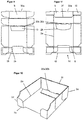
- a blank 1 is shown in its flat transport state.
- the blank 1 is provided with a plurality of creasing or bending lines 2a, 2b, 2c, 2d, 2e, 2f, 2g, through which a bottom 3, side walls 4, a front wall 5, a rear wall 6, connecting tabs 7 and 8, a retaining tab. 9 and carding pockets 10 are defined.
- the bottom 3 is rectangular in the illustrated embodiment in that the bottom 3 bounding crease lines or bends 2a, 2b, 2c perpendicular to each other.
- the substantially rectangular-shaped side walls 4 are pivotally articulated. The side walls 4 are therefore integrally connected to the bottom 3.
- the front wall 5 is articulated, whose lateral edges are also defined by creasing or bending lines 2 d, via which the connecting straps 7 are hinged to the front wall 5. Also, the front wall 5 with the connecting plates 7 is thus integrally connected to the bottom 3.
- the in Fig. 1 the substantially rectangular-shaped side walls 4 are pivotally articulated. The side walls 4 are therefore integrally connected to the bottom 3.
- the front wall 5 is articulated, whose lateral edges are also defined by creasing or bending lines 2 d, via which the connecting straps 7 are hinged to the front wall 5.
- the front wall 5 with the connecting plates 7 is thus integrally connected to the bottom 3.
- FIG. 1 upper side of the bottom 3 is hinged via a crease or bending line the rear wall.
- the lateral edges of the rear wall 6 are in turn defined by creasing or bending lines 2 e, via which the connecting straps 8 are hinged to the rear wall 6.
- FIG. 1 Upper side of the rear wall 6 is hinged on a double creasing or bending line 2 f, the retaining tab 9, which in turn is connected via lateral creasing or bending lines 2 g with the card shackles 10.
- the rear wall 6, the connecting straps 8, the retaining tab 9 and the card shackle 10 are also integrally connected to the bottom 3.
- the creasing or bending lines 2d, 2e which connect the connecting straps 7 and 8 to the front wall 5 and the rear wall 6 in the illustrated embodiment with respect to the creasing or bending lines 2a, which connect the bottom 3 with the side walls 4 by about one Material thickness in Fig. 1 arranged offset outwards. This causes when erecting the blank 1 to a packaging, the connection tabs 7 can be mounted on the outside of the side walls 4, without causing a tension of the packaging.
- a locking tab 11 is formed by a recess 12 is provided in the region of the creasing or bending line 2c, which connects the bottom 3 with the rear wall 6 and this substantially substantially extending incisions 13 in the Floor 3 are formed. Via a further creasing or bending line 2h the locking tab 11 is pivotally connected to the bottom 3.
- a removal opening 14 is provided in the front wall 5, which extends slightly beyond the bottom or the bottom wall 3 with the front wall connecting groove or bend line 2b in the region of the bottom 3.
- the removal opening 14 is provided centrally in the front wall 5, so that webs of the front wall 5 extend on both sides of the removal opening 14.
- the blank 1 according to the invention is provided with an elastic element 15, which in the illustrated embodiment is a strip or a band made of latex.
- the elastic band 15 has substantially the width of the front wall 5 including the connecting tabs 7, so that the elastic band 15 can be placed on the connecting tabs 7 and the front wall 5, wherein the free ends of the elastic band 5 approximately in the vicinity of the free lateral Edge of the connection tabs 7 come to rest.
- the elastic band 15 is adhesively bonded to the two connecting straps 7, so that a central region of the elastic band 15, which covers the front wall and the removal opening 14 in regions, rests loosely on the blank 1 only at the two ends.
- the erection of a package according to the invention from the blank after Fig. 1 explained in more detail.
- the side walls 4 and the front wall 5 and the rear wall 6 are pivoted relative to the bottom 3 by about 90 °.
- the connecting tabs 7 and 8 are also pivoted about 90 ° and fixed from the outside on the upright side walls 4. This can be done conveniently by gluing. Alternatively, this can be done, for example, by means of brackets.
- the lateral ends of the elastic band 15 are clamped between the connecting tab 7 and the outside of the side walls 4 and connected to both the respective connecting tab 7 and the respective side wall 4.
- the elastic band 15 thus extends partially along the erected side walls 4 and inwardly parallel to the front wall 5, but without being firmly connected thereto. This condition is in Fig. 2 shown.
- the elastic band 15 can now be tensioned. It proves to be an advantage that the packaging is already fully erected and the side walls are connected to the front wall 5 and the rear wall 6, so that the package has sufficient stability. As explained in more detail below, the elastic band is stretched so that it is as in Fig. 3 shown inside approximately parallel to the side walls and parallel to the rear wall 6 extends. In this state, the retaining tab 9 can be pivoted by 180 ° inwards, so that this clamps the elastic band 15 between itself and the rear wall 6. Previously, the card shackles 10 have been folded onto the retaining tab 9, so that the card shackles 10 abut the elastic band 15.
- the retaining tab 9 can be locked in this position against the tension of the elastic band 15 by the locking tab 11 is slightly deflected out of the plane of the bottom 3 upwards. This pushes the the rear wall 6 facing free edge of the locking tab 11 approximately at right angles to the in Fig. 4 lower side of the retaining tab 9 and thus prevents the retaining tab 9 by the restoring force of the elastic band 15 in Fig. 4 is pivoted forward or back up.
- the elastic band 15 first presses the products still remaining in the packaging in the direction of the front wall 5 via the retention tab 9. After some products have been removed from the packaging, the retaining tab 9 is pivoted by the restoring force of the elastic band 15 so far that it extends, for example, approximately parallel to the bottom 3. Already shortly before reaching this state, the elastic band 15 slips off the retaining tab 9 and exerts a pulling force in the direction of the front wall 5 directly on the products still remaining in the package. The elastic band 15 thus encloses the remaining products in the package laterally and from the back. This prevents that the products, for example, tabular products, fall over in the packaging and are thus less recognizable or removable by a consumer through the removal opening 14.
- Fig. 2 to 4 is the erected from the blank 1 packaging in the form of an open-topped tray (Scdazzling) shown.
- the tray can be closed after filling by a cover having a bottom surface 3 opposite top surface and hinged thereto peripheral walls.
- the peripheral walls can, for example, rest on the outside of the side walls 4 and the rear wall 6.
- Another peripheral wall can be inserted into the packaging, so that it rests against the inside of the front wall and thus closes the removal opening 14.
- this additional peripheral wall on the outside of the front wall.
- at least a portion of the top surface and / or the peripheral wall of the cover associated with the front wall is designed to be tearable or tearable, so that the packaging provided with the cover can be easily opened.
- FIGS Fig. 5 to 8 The process of tensioning the elastic band 15 and the locking of the elastic band 15 by means of the retaining tab 9 and the locking tab 11 will be described below with reference to FIGS Fig. 5 to 8 explained in more detail.
- a station is shown in which the as in Fig. 2 shown erected packaging introduced and in the state Fig. 4 is transferred.
- the station 20 initially has a receptacle for the packaging, which is formed by a bottom 21, side walls 22 and a rear wall 23.
- the recording is thus on the in Fig. 5 open on the right side so that the packaging can be inserted into the receptacle.
- four openings are provided in the bottom 21 through which suction members 24 can hold the bottom 3 of the package within the receptacle.
- a plate 25 is arranged, in which two slotted guides 26 are provided.
- the slide guides 26 are shown in the Embodiment designed as an approximately s-shaped opening or groove in which in each case a sheet 27 is slidably guided.
- the plates 27 are connected via a non-illustrated drive from the in Fig. 5 dashed shown right position in the left position shown by solid lines.
- the two bearings of the sheets 27 are also in Fig. 7 represented by two dashed or two solid circles in the different positions of the sheets.
- the slide guides 26 in the plate 25 are designed so that the sheets 27 can move through the removal opening 14 in the front wall 5 into the package inside.
- the elastic band 15 with the in Fig. 5 left edge of the respective plates 27 in Appendix.
- the plates 27 thus serve as manipulators that urge the elastic band in the corners of the side walls 4 with the rear wall 6 by the sheets 27 along the slide guide 26 in Fig. 5 to be moved to the left.
- the elastic band 15 is tensioned.
- the sheets 27 are preferably made comparatively thin, so that the sheets 27 in their in Fig. 5 Left position as close to the inside of the side walls 4 rest, without hindering the turning of the retaining tab 9.
- an angle 28 is provided in the station 20, whose width is as in Fig. 8 shown, which corresponds approximately to the retaining tab 9.
- the angle 28 is out of his in Fig. 5 shown position via a non-illustrated drive in a clockwise direction, so that the in Fig. 5 longer vertical leg of the angle 28 touches the retaining tab 9 and folds up on the rear wall 6.
- the angle 28 brings in operation, the retaining tab 9 from the in Fig. 3 shown position in the Fig. 4 shown position.
- a cylinder unit 29 is provided, the plunger through a further opening of the bottom 21 on the locking tab 11 of Packaging can act.
- the cylinder unit 29 is actuated and thereby pivots the locking tab 11 slightly out of its lying in the plane of the bottom 3 position into the interior of the package, so that the free edge of the locking tab 11 with the lower side of the retaining tab. 9 comes into contact.
- This prevents the retaining tab 9 is pivoted back by the force of the elastic band 15 when the angle 28 in his in Fig. 5 shown starting position returns and the sheets 27 back into the in Fig. 5 right position.
- the packaging is thus in a state after Fig. 4 in which the packaging can be filled.
- the elastic band 15 is stretched by the sheets 27 as described above, and the package must then be filled as long as the sheets 27 keep the elastic band 15 taut.
- the elastic band 15 acts directly on the products as soon as the sheets 27 are disengaged from the band 15.
- the station 20 may be preceded by a further station, not shown in the figures, in which the package is erected from the blank 1 and glued.
- This upstream station can, for example, as in the unpublished international patent application PCT / GB2013 / 051755 be designed described.
- the elastic band 15 can be applied to the blank 1 in a device 20 upstream of the station. This can be done, for example, by unrolling elastic strip material from a roll whose width corresponds approximately to the distance between the free lateral edges of the connecting straps 7 and applied to a substrate. This pad is preferably connected to a suction device, so that the unwound material is held on the pad. On this base, the unwound material can then be cut into strips of a height suitable for feeding the products in the package. This cut strip can then be fed to the blank 1 and glued to it at the connecting tabs 7.
- FIGS. 9 and 10 a second embodiment is shown, which is similar to the first embodiment of the basic structure ago.
- Upper side of the retaining tab 9 Upper side of the retaining tab 9, however, cutouts 30 a are provided.
- Corresponding cutouts 30b are also provided on the rear wall 6 facing free edge of the locking tab 6.
- Fig. 10 shows, in which the elastic band 15 has been omitted for clarity, these cutouts 30a, 30b cause a toothing, which prevents in the erected state of the locking tab 11, that this is urged by the force of the elastic band 15 from the retaining tab 9 arresting position can be.
- the locking tab 11 and the retaining tab 9 engage with each other to secure over the retaining tab 9, the elastic member 15.
- FIG. 11 A modification of this embodiment is in Fig. 11 shown.
- the creasing or bending line 2h via which the locking tab 11 is connected to the bottom 3, designed curved.
- This increases the restoring force.
- the cuts 13 are designed obliquely.
- the rear wall 6 is designed shortened compared to the other embodiments. Accordingly, the height of the card shackles 10 is smaller. Therefore, in order to avoid a sharp edge with the connecting tab 8, the double creasing or bending line 2f does not extend over the entire width of the rear wall 6 and extend starting from the ends of the double creasing line. or bending line 2f oblique incisions to the respective corners of the connecting tabs 8.
Landscapes
- Engineering & Computer Science (AREA)
- Mechanical Engineering (AREA)
- Transportation (AREA)
- Cartons (AREA)
- Making Paper Articles (AREA)
- Packages (AREA)
Priority Applications (1)
| Application Number | Priority Date | Filing Date | Title |
|---|---|---|---|
| PL14798817T PL3068700T3 (pl) | 2013-11-14 | 2014-11-12 | Sposób i instalacja do wytwarzania opakowania |
Applications Claiming Priority (2)
| Application Number | Priority Date | Filing Date | Title |
|---|---|---|---|
| DE102013112566.2A DE102013112566A1 (de) | 2013-11-14 | 2013-11-14 | Verfahren und Anlage zur Herstellung einer Verpackung |
| PCT/EP2014/074398 WO2015071327A1 (de) | 2013-11-14 | 2014-11-12 | Verfahren und anlage zur herstellung einer verpackung |
Publications (2)
| Publication Number | Publication Date |
|---|---|
| EP3068700A1 EP3068700A1 (de) | 2016-09-21 |
| EP3068700B1 true EP3068700B1 (de) | 2018-01-03 |
Family
ID=51900413
Family Applications (1)
| Application Number | Title | Priority Date | Filing Date |
|---|---|---|---|
| EP14798817.4A Active EP3068700B1 (de) | 2013-11-14 | 2014-11-12 | Verfahren und anlage zur herstellung einer verpackung |
Country Status (17)
| Country | Link |
|---|---|
| US (1) | US10486842B2 (ja) |
| EP (1) | EP3068700B1 (ja) |
| JP (1) | JP6577467B2 (ja) |
| CN (2) | CN111376523A (ja) |
| AU (3) | AU2014350254B2 (ja) |
| CA (1) | CA2928633C (ja) |
| DE (2) | DE202013012317U1 (ja) |
| DK (1) | DK3068700T3 (ja) |
| EA (1) | EA031778B1 (ja) |
| ES (1) | ES2662798T3 (ja) |
| HU (1) | HUE036298T2 (ja) |
| MX (1) | MX2016006246A (ja) |
| PL (1) | PL3068700T3 (ja) |
| PT (1) | PT3068700T (ja) |
| TR (1) | TR201802713T4 (ja) |
| UA (1) | UA117386C2 (ja) |
| WO (1) | WO2015071327A1 (ja) |
Families Citing this family (11)
| Publication number | Priority date | Publication date | Assignee | Title |
|---|---|---|---|---|
| GB2503677B (en) | 2012-07-03 | 2016-05-11 | Ds Smith Packaging Ltd | Product pusher |
| DE202013012317U1 (de) | 2013-11-14 | 2016-03-17 | Ds Smith Packaging Deutschland Stiftung & Co. Kg | Verpackung und Anlage zur Herstellung einer Verpackung |
| GB2530547A (en) * | 2014-09-25 | 2016-03-30 | Smurfit Kappa Uk Ltd | Shelf ready packaging |
| US10798922B1 (en) * | 2015-02-23 | 2020-10-13 | Jill Adele Woods | Bee installation funnel and associated assembly and method for using the same |
| US10987889B2 (en) | 2015-09-21 | 2021-04-27 | Westrock Shared Services, Llc | Methods and machine for forming a shipping container with an article retaining web |
| GB2545160B (en) * | 2015-11-05 | 2020-04-29 | Ds Smith Packaging Ltd | Packaging |
| WO2018085272A1 (en) | 2016-11-01 | 2018-05-11 | Kraft Foods R&D, Inc. | Integrated pulling system with back flap |
| US11400679B2 (en) | 2018-04-10 | 2022-08-02 | Westrock Shared Services, Llc | Machine and methods for attaching a tray blank to a cover blank |
| US10899101B2 (en) | 2018-04-10 | 2021-01-26 | Westrock Shared Services, Llc | Machine and methods for attaching retaining web to container blank |
| CN109823620B (zh) * | 2019-03-20 | 2023-12-15 | 深圳市联欣科技有限公司 | 自动折膜绕线扣膜设备 |
| CN109896086B (zh) * | 2019-03-20 | 2024-01-09 | 深圳市联欣科技有限公司 | 膜片扣膜结构 |
Family Cites Families (98)
| Publication number | Priority date | Publication date | Assignee | Title |
|---|---|---|---|---|
| US2735553A (en) * | 1956-02-21 | lehman | ||
| US1593532A (en) | 1925-04-02 | 1926-07-20 | Emil J Hansen | Toilet-paper-dispensing device |
| US1718572A (en) | 1927-07-30 | 1929-06-25 | Moses M Marcuse | Cigarette package |
| US1959614A (en) | 1933-10-20 | 1934-05-22 | Tissue Company | Napkin package |
| US2185605A (en) | 1938-04-25 | 1940-01-02 | John M Murphy | Package accessory |
| US2331035A (en) | 1940-01-22 | 1943-10-05 | Axel H Lundstrom | Package jack |
| US2634855A (en) | 1951-09-04 | 1953-04-14 | Mandel Jacob | Tissue dispensing device |
| US2774467A (en) | 1956-08-31 | 1956-12-18 | Michiel Joseph | Dispensing device for packaged merchandise |
| US2937742A (en) | 1958-04-07 | 1960-05-24 | Michiel Joseph | Dispensing device for merchandise |
| US3122236A (en) | 1962-11-05 | 1964-02-25 | Michiel Joseph | Dispensing device for merchandise |
| US3202316A (en) | 1963-09-24 | 1965-08-24 | Electro Nite Inc | Biased stack facial tissue dispenser |
| DE1293429C2 (de) | 1964-07-13 | 1973-05-03 | Buenger Bob Textil | Behaelter zum Aufnehmen eines Stapels von Wareneinheiten, wie Packungen von Kurzwarenartikeln, und zum Ausgeben der jeweils vordersten Einheit des Stapels |
| US3373922A (en) | 1965-07-16 | 1968-03-19 | Reynolds Metals Co | Container and blanks for making the same |
| DE1554649A1 (de) | 1966-11-24 | 1970-03-12 | Buenger Bob Textil | Verkaufs- und Lagerbehaelter fuer textile Kurzwaren |
| US3591049A (en) | 1969-11-06 | 1971-07-06 | Universal Oil Prod Co | Bottle storage and dispensing unit |
| US3647114A (en) | 1969-12-01 | 1972-03-07 | Keith T Bleuer | Tissue dispenser having resiliently biased follower |
| FR2215819A5 (ja) | 1973-01-26 | 1974-08-23 | Michel Marcel | |
| DE7510538U (de) | 1975-04-04 | 1975-08-21 | Parco Nahrungs Und Genussmitte | Schachtel mit Spendevorrichtung fuer einzelne Zigarettenpackungen |
| US4020946A (en) | 1975-09-29 | 1977-05-03 | Gardner Marshall J | Display and dispensing carton structure and blank therefor |
| DE3231787A1 (de) | 1982-08-26 | 1984-03-01 | BKW Handels- und Vertriebsgesellschaft, 6940 Weinheim | Transportable strahlgutschleuder |
| JPS5938224U (ja) * | 1982-08-31 | 1984-03-10 | 本州製紙株式会社 | 段ボ−ル製包装箱 |
| US4588093A (en) | 1982-12-20 | 1986-05-13 | Field Frank P | Merchandise display device |
| JPS59128272U (ja) * | 1983-02-17 | 1984-08-29 | レンゴ−株式会社 | 陳列ケ−ス |
| JPS59193180U (ja) | 1983-06-09 | 1984-12-21 | 清藤 三津郎 | テイツシユペ−パ−ボツクス |
| DE8328422U1 (de) | 1983-10-03 | 1984-01-19 | August Storck Kg, 4802 Halle | Regalsteller fuer waren |
| JPS6331865U (ja) | 1986-08-20 | 1988-03-01 | ||
| FR2628357B1 (fr) * | 1988-03-09 | 1994-10-28 | Neyret Guy | Dispositif plieur et machine de fabrication de barquettes utilisant un tel dispositif |
| US4844331A (en) | 1988-06-24 | 1989-07-04 | Boise Cascade Corporation | Self-locking corner structure |
| FR2646398B1 (fr) * | 1989-04-26 | 1992-07-31 | Bello Martino | Perfectionnements apportes a une machine autorisant la mise en forme de plateaux d'emballage pour le conditionnement et l'expedition de fruits et/ou legumes |
| US5161702A (en) | 1989-11-14 | 1992-11-10 | Thomas A. Schutz Company | Display device |
| FR2678247B1 (fr) | 1991-06-25 | 1994-10-28 | Kaysersberg Sa | Emballage formant distributeur pour produits plats et souples. |
| US5197631A (en) | 1991-12-06 | 1993-03-30 | Eiichi Mishima | Mechanism for automatically pushing up tissues |
| EP0573381B1 (en) * | 1992-06-03 | 2000-09-20 | Videcart, S.A. | Stackable cardboard tray |
| JPH06255685A (ja) * | 1993-06-25 | 1994-09-13 | Tokiwa Kogyo:Kk | 包装用容器 |
| US5393291A (en) | 1993-07-08 | 1995-02-28 | Marq Packaging Systems, Inc. | Mini case erector |
| JPH07291372A (ja) | 1994-04-22 | 1995-11-07 | Minoru Inagaki | ポケットテッシュ収納箱 |
| DE4443775C2 (de) | 1994-12-08 | 1997-12-11 | Eichler Projektierungs & Planu | Selbsttätige Verpackungseinheit in einem Ladenregal |
| JPH0948422A (ja) * | 1995-08-10 | 1997-02-18 | Nippon Shiki Kk | 包装用箱 |
| JPH09224789A (ja) | 1996-02-23 | 1997-09-02 | Sanko Hatsujo Kk | 物品押出装置 |
| JP3031835U (ja) * | 1996-05-30 | 1996-12-03 | 江戸川段ボール工業株式会社 | 商品陳列ケース |
| JPH107129A (ja) | 1996-06-19 | 1998-01-13 | Furou:Kk | 外 箱 |
| FR2762502B1 (fr) | 1997-04-29 | 1999-07-16 | Smurfit Socar Sa | Nouvelle barquette en un materiau semi-rigide, pour l'exposition en vente d'articles divers |
| US5988407A (en) | 1997-08-28 | 1999-11-23 | L&P Property Management Company | Merchandising shelf assembly |
| US6015051A (en) | 1997-08-28 | 2000-01-18 | L&P Property Management Company | Shelf assembly with pusher having memory characteristic and method of use |
| US6082558A (en) | 1997-08-28 | 2000-07-04 | L&P Property Management Company | Shelf assembly with pusher having memory characteristic and method of use |
| US5992683A (en) | 1998-08-31 | 1999-11-30 | Kimberly-Clark Worldwide, Inc. | Clip lift for sheet dispensing system |
| DE29908078U1 (de) | 1999-05-06 | 1999-10-07 | Thimm GmbH, 37154 Northeim | Wellpapp-Warenschieber mit umlegbarer Zug- und Schiebelasche |
| US6227386B1 (en) | 1999-05-14 | 2001-05-08 | James Garth Close | System and method for product display, arrangement and rotation |
| US6109458A (en) | 1999-05-27 | 2000-08-29 | Frontline, Inc. | Product advancement roll |
| JP2001017281A (ja) | 1999-07-08 | 2001-01-23 | Kawajun Kk | 商品陳列具 |
| US6193067B1 (en) | 1999-09-03 | 2001-02-27 | Mcmahan Timothy C. | Self-fronting merchandise display box |
| US6454107B1 (en) * | 2000-01-24 | 2002-09-24 | International Paper Company | Shipping and display container |
| FI108843B (fi) | 2000-03-09 | 2002-04-15 | Man Metalli Oy | Siirtojärjestely |
| SE516038C2 (sv) | 2000-03-20 | 2001-11-12 | Foldy Pac Trading Ab | Förbindningsanordning, låda och spännbygel |
| AT409366B (de) | 2000-06-20 | 2002-07-25 | Haas Beteiligungsgesellschaft | Magazin zur aufnahme und vereinzelten abgabe von tabletten |
| GB2378178B (en) | 2001-07-31 | 2005-03-30 | Sca Packaging Ltd | Packaging |
| US20050072747A1 (en) | 2002-05-10 | 2005-04-07 | Roslof James P. | Merchandising system |
| JP4096332B2 (ja) * | 2002-06-18 | 2008-06-04 | ヤマト包装技術研究所株式会社 | 缶・瓶類の運送用プロテクタ |
| US20040178157A1 (en) | 2003-03-15 | 2004-09-16 | Tse Hing Fai Gary | Display rack |
| DE10314232A1 (de) | 2003-03-27 | 2004-10-14 | Thimm Verpackung Gmbh & Co. Kg | Verpackung mit Schieber für die abverkaufsgerechte Präsentation von Packgütern im Handel |
| JP3097744U (ja) * | 2003-05-13 | 2004-02-05 | 坂本 功勝 | 商品前出し陳列具 |
| DE20316963U1 (de) | 2003-11-02 | 2005-03-17 | Thimm Verpackung Gmbh & Co Kg | Präsentationsverpackung mit Schieber |
| DE10352206B4 (de) | 2003-11-05 | 2010-12-16 | Thimm Verpackung Gmbh + Co. Kg | Warenverpackung |
| US20050161413A1 (en) | 2003-12-03 | 2005-07-28 | Close James G. | Method and apparatus for in-carton display and fronting of merchandise items |
| DE102004015701B3 (de) | 2004-03-29 | 2005-07-21 | Thimm Verpackung Gmbh & Co. Kg | Verpackung für die abverkaufsgerechte Präsentation von Waren und Einsatz für eine Verkaufsverpackung |
| DE102004015576B4 (de) | 2004-03-30 | 2006-08-17 | Gustav Stabernack Gmbh | Regaltray mit elastischem Rückzugmittel |
| US8997997B2 (en) | 2004-04-30 | 2015-04-07 | Close-In Solutions, LLC | Apparatus and method for product display alignment |
| US7284662B2 (en) | 2004-05-04 | 2007-10-23 | Graphic Packaging International, Inc. | Retail dispensing and display carton |
| US7481313B1 (en) * | 2005-09-26 | 2009-01-27 | The Hammer Corporation | Candy display system |
| US7497342B2 (en) | 2005-10-25 | 2009-03-03 | Rtc Industries, Inc. | Product management display system |
| US20070108083A1 (en) | 2005-11-15 | 2007-05-17 | Sonon James A | Tray with fronting member, associated displays and methods |
| DE102005056162A1 (de) | 2005-11-23 | 2007-07-12 | Mtc Trading Company Gmbh | Verpackungs- und Displaykarton |
| CN2882432Y (zh) | 2005-12-22 | 2007-03-28 | 苏南 | 一种弹性自动送烟包装置 |
| CN2855724Y (zh) * | 2005-12-31 | 2007-01-10 | 武建 | 一种制作翻盖烟盒用的能展示和发布信息的易撕开卡纸片 |
| US20130037562A1 (en) | 2006-01-13 | 2013-02-14 | James Garth Close | Spring driven method and apparatus for in-carton display and fronting of merchandise items |
| US7896172B1 (en) | 2006-01-31 | 2011-03-01 | Hester Thomas F | Compactable product pusher system and display |
| DE202006007162U1 (de) | 2006-05-03 | 2006-12-28 | Sca Verpackung + Display Vertriebsgesellschaft Mbh & Co. Kg | Warenvorschubsystem |
| CN100570643C (zh) | 2006-09-27 | 2009-12-16 | 广东省电子技术研究所 | 一种发卡机 |
| CN201026050Y (zh) | 2007-05-24 | 2008-02-27 | 王杰 | 一种敞开式药品柜 |
| US20090020548A1 (en) | 2007-07-18 | 2009-01-22 | Rapid Displays, Inc. | Pusher and merchandise display system |
| DE102007034862B4 (de) | 2007-07-24 | 2009-05-28 | Thimm Verpackung Gmbh & Co. Kg | Verfahren zur Herstellung einer Verpackung und Warenschieber zum Einsatz in einer Verpackung |
| DE202007011163U1 (de) | 2007-08-09 | 2008-02-14 | Sca Verpackung + Display Vertriebsgemeinschaft Mbh | Verpackung mit Warenvorschubsystem |
| DE102007042764A1 (de) | 2007-09-07 | 2009-03-12 | Heuchemer Verpackung Gmbh & Co. Kg | Verpackung |
| US7997427B2 (en) | 2008-08-25 | 2011-08-16 | Pepsico, Inc. | Merchandise display system |
| CA2742441A1 (en) * | 2008-10-31 | 2010-05-06 | Dimitri Tosevski | Assembly of a cardboard tray |
| FR2943319B1 (fr) * | 2009-03-20 | 2016-10-14 | Otor Sa | Plateau,ensemble de flans en carton,dispositif et procede pour former un tel plateau |
| IT1393009B1 (it) | 2009-03-26 | 2012-04-11 | Kartè Srl | Spintore elastico per espositori e supporti pubblicitari autoportanti. |
| FR2953385A1 (fr) | 2009-12-04 | 2011-06-10 | Julien Robert Pierre Sylvain | Module de soutenement en materiau semi-rigide et lit forme a partir de cet objet |
| DE102010053042A1 (de) | 2010-09-28 | 2012-03-29 | Torsten Brandt | Verkaufskarton mit einer Warenvorschubvorrichtung |
| CN201948530U (zh) | 2010-11-30 | 2011-08-31 | 李蛟 | 货架专用助推器 |
| US8646621B2 (en) | 2011-03-16 | 2014-02-11 | Meadwestvaco Corporation | Product biasing and dispensing system with security engagement |
| JP3171773U (ja) | 2011-09-03 | 2011-11-17 | 邦章 深山 | ティッシュボックスおよびその組み立てセット |
| GB2503677B (en) | 2012-07-03 | 2016-05-11 | Ds Smith Packaging Ltd | Product pusher |
| GB2508808B (en) | 2012-11-06 | 2015-09-02 | Kraft Foods Uk R & D Ltd | Pusher |
| US8758860B1 (en) | 2012-11-07 | 2014-06-24 | Bayer Materialscience Llc | Process for incorporating an ion-conducting polymer into a polymeric article to achieve anti-static behavior |
| DE202013012311U1 (de) | 2013-11-14 | 2016-03-02 | Ds Smith Packaging Deutschland Stiftung & Co. Kg | Zuschnitt und hieraus hergestellte Verpackung |
| DE202013012317U1 (de) | 2013-11-14 | 2016-03-17 | Ds Smith Packaging Deutschland Stiftung & Co. Kg | Verpackung und Anlage zur Herstellung einer Verpackung |
| GB2545160B (en) | 2015-11-05 | 2020-04-29 | Ds Smith Packaging Ltd | Packaging |
-
2013
- 2013-11-14 DE DE202013012317.6U patent/DE202013012317U1/de not_active Expired - Lifetime
- 2013-11-14 DE DE102013112566.2A patent/DE102013112566A1/de active Pending
-
2014
- 2014-11-12 PT PT147988174T patent/PT3068700T/pt unknown
- 2014-11-12 CN CN202010097258.3A patent/CN111376523A/zh active Pending
- 2014-11-12 DK DK14798817.4T patent/DK3068700T3/en active
- 2014-11-12 WO PCT/EP2014/074398 patent/WO2015071327A1/de active Application Filing
- 2014-11-12 EP EP14798817.4A patent/EP3068700B1/de active Active
- 2014-11-12 CA CA2928633A patent/CA2928633C/en active Active
- 2014-11-12 EA EA201600389A patent/EA031778B1/ru not_active IP Right Cessation
- 2014-11-12 HU HUE14798817A patent/HUE036298T2/hu unknown
- 2014-11-12 AU AU2014350254A patent/AU2014350254B2/en not_active Ceased
- 2014-11-12 CN CN201480062421.5A patent/CN106687380B/zh not_active Expired - Fee Related
- 2014-11-12 JP JP2016530951A patent/JP6577467B2/ja active Active
- 2014-11-12 MX MX2016006246A patent/MX2016006246A/es active IP Right Grant
- 2014-11-12 ES ES14798817.4T patent/ES2662798T3/es active Active
- 2014-11-12 TR TR2018/02713T patent/TR201802713T4/tr unknown
- 2014-11-12 US US15/033,633 patent/US10486842B2/en active Active
- 2014-11-12 PL PL14798817T patent/PL3068700T3/pl unknown
- 2014-12-11 UA UAA201606270A patent/UA117386C2/uk unknown
-
2018
- 2018-07-05 AU AU2018204905A patent/AU2018204905B2/en not_active Ceased
-
2020
- 2020-05-27 AU AU2020203486A patent/AU2020203486B2/en not_active Ceased
Also Published As
| Publication number | Publication date |
|---|---|
| JP2016540661A (ja) | 2016-12-28 |
| CN106687380B (zh) | 2020-03-13 |
| AU2018204905B2 (en) | 2020-02-27 |
| TR201802713T4 (tr) | 2018-03-21 |
| DE102013112566A1 (de) | 2015-05-21 |
| ES2662798T3 (es) | 2018-04-09 |
| CA2928633A1 (en) | 2015-05-21 |
| WO2015071327A1 (de) | 2015-05-21 |
| EA031778B1 (ru) | 2019-02-28 |
| EA201600389A1 (ru) | 2016-10-31 |
| CA2928633C (en) | 2018-09-04 |
| UA117386C2 (uk) | 2018-07-25 |
| AU2020203486B2 (en) | 2021-04-22 |
| CN106687380A (zh) | 2017-05-17 |
| MX2016006246A (es) | 2017-02-02 |
| CN111376523A (zh) | 2020-07-07 |
| US10486842B2 (en) | 2019-11-26 |
| DK3068700T3 (en) | 2018-03-26 |
| EP3068700A1 (de) | 2016-09-21 |
| HUE036298T2 (hu) | 2018-06-28 |
| DE202013012317U1 (de) | 2016-03-17 |
| PT3068700T (pt) | 2018-03-23 |
| AU2018204905A1 (en) | 2018-07-26 |
| AU2014350254A1 (en) | 2016-07-07 |
| AU2014350254B2 (en) | 2018-04-05 |
| PL3068700T3 (pl) | 2018-06-29 |
| AU2020203486A1 (en) | 2020-06-18 |
| US20160280407A1 (en) | 2016-09-29 |
| JP6577467B2 (ja) | 2019-09-18 |
Similar Documents
| Publication | Publication Date | Title |
|---|---|---|
| EP3068700B1 (de) | Verfahren und anlage zur herstellung einer verpackung | |
| EP3068699B1 (de) | Zuschnitt und hieraus hergestellte verpackung | |
| DE202013012351U1 (de) | Erzeugnisvordrücker | |
| EP2532513B1 (de) | Beutel für Tabak sowie Verfahren und Vorrichtung zum Herstellen | |
| DE60001400T2 (de) | Faltschachtel, zuschnitte, verfahren zur öffnung einer faltschachtel sowie verfahren und maschine zum herstellen von einer solchen faltschachtel | |
| EP2423116B1 (de) | Flügelfixierverpackung | |
| EP1066154A1 (de) | Beutelherstellverfahren | |
| EP0639503B1 (de) | Kartonierer | |
| EP1517836A1 (de) | Umreifungsvorrichtung | |
| DE102017123706A1 (de) | Verfahren und Verpackungsmaschine zur Herstellung von Multipacks | |
| EP4277850A1 (de) | Umreifungsvorrichtung und verfahren zur herstellung von umreifungsgebinden | |
| DE2612458C2 (de) | Verfahren zum Aufrichten und Verkleben von zunächst ebenen, mit Falzlinien und Klebeflächen versehenen Kartonzuschnitten und zum Verpacken von Behältern in den entstehenden Kartons | |
| EP0579147B1 (de) | Vorrichtung und Verfahren zum Öffnen von Falzbögen | |
| EP2636604A1 (de) | Verfahren zum Herstellen einer Banderole um ein Packgut und Banderoliermaschine hierzu | |
| DE112020003754T5 (de) | Systeme, Verfahren und Vorrichtungen zum Verbinden von Bogenmaterialien | |
| DE60109475T2 (de) | Schachtel sowie schachtelzuschnitt | |
| EP2248721A1 (de) | Vorrichtung und Verfahren zum Verpacken von Objekten | |
| DE102014100779A1 (de) | Verpackungsbehälter, insbesondere für abgewinkeltes Packgut | |
| EP2653393B1 (de) | Verfahren und Vorrichtung zum Umreifen eines Stapels von flächigen, flachen Produkten | |
| EP3020655A1 (de) | Verkaufsverpackung | |
| DE102015204414A1 (de) | Verkaufsverpackung | |
| DE20019140U1 (de) | Vorrichtung zum Verformen von flachliegenden Kartonzuschnitten und damit hergestellter Karton | |
| DE102021114446A1 (de) | Karton sowie Verfahren zum Halten mindestens eines Gegenstandes in einem Karton | |
| DE2139884C3 (de) | Vorrichtung zum Handhaben von aus Kartonzuschnitten herstellbaren Faltbehältern | |
| EP0812768A1 (de) | Vorrichtung zum Falten und Einbringen eines Beipackzettels |
Legal Events
| Date | Code | Title | Description |
|---|---|---|---|
| PUAI | Public reference made under article 153(3) epc to a published international application that has entered the european phase |
Free format text: ORIGINAL CODE: 0009012 |
|
| 17P | Request for examination filed |
Effective date: 20160414 |
|
| AK | Designated contracting states |
Kind code of ref document: A1 Designated state(s): AL AT BE BG CH CY CZ DE DK EE ES FI FR GB GR HR HU IE IS IT LI LT LU LV MC MK MT NL NO PL PT RO RS SE SI SK SM TR |
|
| AX | Request for extension of the european patent |
Extension state: BA ME |
|
| DAX | Request for extension of the european patent (deleted) | ||
| GRAP | Despatch of communication of intention to grant a patent |
Free format text: ORIGINAL CODE: EPIDOSNIGR1 |
|
| STAA | Information on the status of an ep patent application or granted ep patent |
Free format text: STATUS: GRANT OF PATENT IS INTENDED |
|
| INTG | Intention to grant announced |
Effective date: 20170726 |
|
| GRAS | Grant fee paid |
Free format text: ORIGINAL CODE: EPIDOSNIGR3 |
|
| GRAA | (expected) grant |
Free format text: ORIGINAL CODE: 0009210 |
|
| STAA | Information on the status of an ep patent application or granted ep patent |
Free format text: STATUS: THE PATENT HAS BEEN GRANTED |
|
| AK | Designated contracting states |
Kind code of ref document: B1 Designated state(s): AL AT BE BG CH CY CZ DE DK EE ES FI FR GB GR HR HU IE IS IT LI LT LU LV MC MK MT NL NO PL PT RO RS SE SI SK SM TR |
|
| REG | Reference to a national code |
Ref country code: GB Ref legal event code: FG4D Free format text: NOT ENGLISH |
|
| REG | Reference to a national code |
Ref country code: CH Ref legal event code: EP Ref country code: AT Ref legal event code: REF Ref document number: 960016 Country of ref document: AT Kind code of ref document: T Effective date: 20180115 |
|
| REG | Reference to a national code |
Ref country code: IE Ref legal event code: FG4D Free format text: LANGUAGE OF EP DOCUMENT: GERMAN |
|
| REG | Reference to a national code |
Ref country code: DE Ref legal event code: R096 Ref document number: 502014006843 Country of ref document: DE |
|
| REG | Reference to a national code |
Ref country code: CH Ref legal event code: NV Representative=s name: ISLER AND PEDRAZZINI AG, CH |
|
| REG | Reference to a national code |
Ref country code: PT Ref legal event code: SC4A Ref document number: 3068700 Country of ref document: PT Date of ref document: 20180323 Kind code of ref document: T Free format text: AVAILABILITY OF NATIONAL TRANSLATION Effective date: 20180316 |
|
| REG | Reference to a national code |
Ref country code: DK Ref legal event code: T3 Effective date: 20180321 |
|
| REG | Reference to a national code |
Ref country code: RO Ref legal event code: EPE |
|
| REG | Reference to a national code |
Ref country code: SE Ref legal event code: TRGR |
|
| REG | Reference to a national code |
Ref country code: NL Ref legal event code: FP |
|
| REG | Reference to a national code |
Ref country code: ES Ref legal event code: FG2A Ref document number: 2662798 Country of ref document: ES Kind code of ref document: T3 Effective date: 20180409 |
|
| REG | Reference to a national code |
Ref country code: LT Ref legal event code: MG4D |
|
| REG | Reference to a national code |
Ref country code: NO Ref legal event code: T2 Effective date: 20180103 |
|
| REG | Reference to a national code |
Ref country code: HU Ref legal event code: AG4A Ref document number: E036298 Country of ref document: HU |
|
| PG25 | Lapsed in a contracting state [announced via postgrant information from national office to epo] |
Ref country code: LT Free format text: LAPSE BECAUSE OF FAILURE TO SUBMIT A TRANSLATION OF THE DESCRIPTION OR TO PAY THE FEE WITHIN THE PRESCRIBED TIME-LIMIT Effective date: 20180103 Ref country code: CY Free format text: LAPSE BECAUSE OF FAILURE TO SUBMIT A TRANSLATION OF THE DESCRIPTION OR TO PAY THE FEE WITHIN THE PRESCRIBED TIME-LIMIT Effective date: 20180103 Ref country code: HR Free format text: LAPSE BECAUSE OF FAILURE TO SUBMIT A TRANSLATION OF THE DESCRIPTION OR TO PAY THE FEE WITHIN THE PRESCRIBED TIME-LIMIT Effective date: 20180103 |
|
| REG | Reference to a national code |
Ref country code: SK Ref legal event code: T3 Ref document number: E 27078 Country of ref document: SK |
|
| PG25 | Lapsed in a contracting state [announced via postgrant information from national office to epo] |
Ref country code: RS Free format text: LAPSE BECAUSE OF FAILURE TO SUBMIT A TRANSLATION OF THE DESCRIPTION OR TO PAY THE FEE WITHIN THE PRESCRIBED TIME-LIMIT Effective date: 20180103 Ref country code: IS Free format text: LAPSE BECAUSE OF FAILURE TO SUBMIT A TRANSLATION OF THE DESCRIPTION OR TO PAY THE FEE WITHIN THE PRESCRIBED TIME-LIMIT Effective date: 20180503 Ref country code: LV Free format text: LAPSE BECAUSE OF FAILURE TO SUBMIT A TRANSLATION OF THE DESCRIPTION OR TO PAY THE FEE WITHIN THE PRESCRIBED TIME-LIMIT Effective date: 20180103 |
|
| REG | Reference to a national code |
Ref country code: GR Ref legal event code: EP Ref document number: 20180400902 Country of ref document: GR Effective date: 20180829 |
|
| PG25 | Lapsed in a contracting state [announced via postgrant information from national office to epo] |
Ref country code: MT Free format text: LAPSE BECAUSE OF FAILURE TO SUBMIT A TRANSLATION OF THE DESCRIPTION OR TO PAY THE FEE WITHIN THE PRESCRIBED TIME-LIMIT Effective date: 20180103 |
|
| REG | Reference to a national code |
Ref country code: DE Ref legal event code: R097 Ref document number: 502014006843 Country of ref document: DE |
|
| PG25 | Lapsed in a contracting state [announced via postgrant information from national office to epo] |
Ref country code: EE Free format text: LAPSE BECAUSE OF FAILURE TO SUBMIT A TRANSLATION OF THE DESCRIPTION OR TO PAY THE FEE WITHIN THE PRESCRIBED TIME-LIMIT Effective date: 20180103 |
|
| PLBE | No opposition filed within time limit |
Free format text: ORIGINAL CODE: 0009261 |
|
| STAA | Information on the status of an ep patent application or granted ep patent |
Free format text: STATUS: NO OPPOSITION FILED WITHIN TIME LIMIT |
|
| PG25 | Lapsed in a contracting state [announced via postgrant information from national office to epo] |
Ref country code: SM Free format text: LAPSE BECAUSE OF FAILURE TO SUBMIT A TRANSLATION OF THE DESCRIPTION OR TO PAY THE FEE WITHIN THE PRESCRIBED TIME-LIMIT Effective date: 20180103 |
|
| 26N | No opposition filed |
Effective date: 20181005 |
|
| PG25 | Lapsed in a contracting state [announced via postgrant information from national office to epo] |
Ref country code: SI Free format text: LAPSE BECAUSE OF FAILURE TO SUBMIT A TRANSLATION OF THE DESCRIPTION OR TO PAY THE FEE WITHIN THE PRESCRIBED TIME-LIMIT Effective date: 20180103 |
|
| PG25 | Lapsed in a contracting state [announced via postgrant information from national office to epo] |
Ref country code: MC Free format text: LAPSE BECAUSE OF FAILURE TO SUBMIT A TRANSLATION OF THE DESCRIPTION OR TO PAY THE FEE WITHIN THE PRESCRIBED TIME-LIMIT Effective date: 20180103 |
|
| PG25 | Lapsed in a contracting state [announced via postgrant information from national office to epo] |
Ref country code: MK Free format text: LAPSE BECAUSE OF NON-PAYMENT OF DUE FEES Effective date: 20180103 |
|
| P01 | Opt-out of the competence of the unified patent court (upc) registered |
Effective date: 20230323 |
|
| PGFP | Annual fee paid to national office [announced via postgrant information from national office to epo] |
Ref country code: IT Payment date: 20230905 Year of fee payment: 10 Ref country code: CZ Payment date: 20230926 Year of fee payment: 10 Ref country code: BG Payment date: 20230926 Year of fee payment: 10 |
|
| PGFP | Annual fee paid to national office [announced via postgrant information from national office to epo] |
Ref country code: PL Payment date: 20230925 Year of fee payment: 10 |
|
| PGFP | Annual fee paid to national office [announced via postgrant information from national office to epo] |
Ref country code: NL Payment date: 20231124 Year of fee payment: 10 Ref country code: LU Payment date: 20231120 Year of fee payment: 10 |
|
| PGFP | Annual fee paid to national office [announced via postgrant information from national office to epo] |
Ref country code: SK Payment date: 20231107 Year of fee payment: 10 |
|
| PGFP | Annual fee paid to national office [announced via postgrant information from national office to epo] |
Ref country code: GB Payment date: 20231123 Year of fee payment: 10 Ref country code: GR Payment date: 20231121 Year of fee payment: 10 |
|
| PGFP | Annual fee paid to national office [announced via postgrant information from national office to epo] |
Ref country code: ES Payment date: 20231201 Year of fee payment: 10 |
|
| PGFP | Annual fee paid to national office [announced via postgrant information from national office to epo] |
Ref country code: TR Payment date: 20231113 Year of fee payment: 10 Ref country code: SE Payment date: 20231121 Year of fee payment: 10 Ref country code: RO Payment date: 20231024 Year of fee payment: 10 Ref country code: PT Payment date: 20231102 Year of fee payment: 10 Ref country code: NO Payment date: 20231121 Year of fee payment: 10 Ref country code: IE Payment date: 20231121 Year of fee payment: 10 Ref country code: HU Payment date: 20231122 Year of fee payment: 10 Ref country code: FI Payment date: 20231120 Year of fee payment: 10 Ref country code: DK Payment date: 20231124 Year of fee payment: 10 Ref country code: DE Payment date: 20231121 Year of fee payment: 10 Ref country code: CH Payment date: 20231201 Year of fee payment: 10 Ref country code: AT Payment date: 20231117 Year of fee payment: 10 |
|
| PGFP | Annual fee paid to national office [announced via postgrant information from national office to epo] |
Ref country code: BE Payment date: 20231120 Year of fee payment: 10 |
|
| PGFP | Annual fee paid to national office [announced via postgrant information from national office to epo] |
Ref country code: FR Payment date: 20240116 Year of fee payment: 10 |
|
| PGFP | Annual fee paid to national office [announced via postgrant information from national office to epo] |
Ref country code: AL Payment date: 20231003 Year of fee payment: 10 |