EP3064302B1 - Drahterosionsmaschine mit funktion zur korrektur des messwerts der drahtspannung - Google Patents
Drahterosionsmaschine mit funktion zur korrektur des messwerts der drahtspannung Download PDFInfo
- Publication number
- EP3064302B1 EP3064302B1 EP16158750.6A EP16158750A EP3064302B1 EP 3064302 B1 EP3064302 B1 EP 3064302B1 EP 16158750 A EP16158750 A EP 16158750A EP 3064302 B1 EP3064302 B1 EP 3064302B1
- Authority
- EP
- European Patent Office
- Prior art keywords
- tensile force
- detected
- detector
- wire electrode
- electric discharge
- Prior art date
- Legal status (The legal status is an assumption and is not a legal conclusion. Google has not performed a legal analysis and makes no representation as to the accuracy of the status listed.)
- Active
Links
- 238000003754 machining Methods 0.000 claims description 22
- 230000001939 inductive effect Effects 0.000 claims description 3
- 238000004804 winding Methods 0.000 description 15
- 238000000034 method Methods 0.000 description 13
- 238000010586 diagram Methods 0.000 description 10
- 238000001514 detection method Methods 0.000 description 7
- 238000007796 conventional method Methods 0.000 description 4
- 238000011084 recovery Methods 0.000 description 3
- 238000011144 upstream manufacturing Methods 0.000 description 3
Images


Classifications
-
- B—PERFORMING OPERATIONS; TRANSPORTING
- B23—MACHINE TOOLS; METAL-WORKING NOT OTHERWISE PROVIDED FOR
- B23H—WORKING OF METAL BY THE ACTION OF A HIGH CONCENTRATION OF ELECTRIC CURRENT ON A WORKPIECE USING AN ELECTRODE WHICH TAKES THE PLACE OF A TOOL; SUCH WORKING COMBINED WITH OTHER FORMS OF WORKING OF METAL
- B23H7/00—Processes or apparatus applicable to both electrical discharge machining and electrochemical machining
- B23H7/02—Wire-cutting
- B23H7/04—Apparatus for supplying current to working gap; Electric circuits specially adapted therefor
-
- B—PERFORMING OPERATIONS; TRANSPORTING
- B23—MACHINE TOOLS; METAL-WORKING NOT OTHERWISE PROVIDED FOR
- B23H—WORKING OF METAL BY THE ACTION OF A HIGH CONCENTRATION OF ELECTRIC CURRENT ON A WORKPIECE USING AN ELECTRODE WHICH TAKES THE PLACE OF A TOOL; SUCH WORKING COMBINED WITH OTHER FORMS OF WORKING OF METAL
- B23H11/00—Auxiliary apparatus or details, not otherwise provided for
-
- B—PERFORMING OPERATIONS; TRANSPORTING
- B23—MACHINE TOOLS; METAL-WORKING NOT OTHERWISE PROVIDED FOR
- B23H—WORKING OF METAL BY THE ACTION OF A HIGH CONCENTRATION OF ELECTRIC CURRENT ON A WORKPIECE USING AN ELECTRODE WHICH TAKES THE PLACE OF A TOOL; SUCH WORKING COMBINED WITH OTHER FORMS OF WORKING OF METAL
- B23H7/00—Processes or apparatus applicable to both electrical discharge machining and electrochemical machining
- B23H7/02—Wire-cutting
- B23H7/08—Wire electrodes
- B23H7/10—Supporting, winding or electrical connection of wire-electrode
- B23H7/104—Wire tension control
-
- B—PERFORMING OPERATIONS; TRANSPORTING
- B23—MACHINE TOOLS; METAL-WORKING NOT OTHERWISE PROVIDED FOR
- B23H—WORKING OF METAL BY THE ACTION OF A HIGH CONCENTRATION OF ELECTRIC CURRENT ON A WORKPIECE USING AN ELECTRODE WHICH TAKES THE PLACE OF A TOOL; SUCH WORKING COMBINED WITH OTHER FORMS OF WORKING OF METAL
- B23H7/00—Processes or apparatus applicable to both electrical discharge machining and electrochemical machining
- B23H7/26—Apparatus for moving or positioning electrode relatively to workpiece; Mounting of electrode
- B23H7/265—Mounting of one or more thin electrodes
Definitions
- the present invention relates to a wire electric discharge machine, and more particularly, to a wire electric discharge machine which detects a tensile force of a wire electrode and performs feedback control of the wire electrode.
- an appropriate tensile force is applied to a wire electrode and electric discharge is carried out.
- vibration of the wire electrode is suppressed and precise machining is obtained.
- the tensile force applied to the wire electrode is excessively strong, there is fear that the wire electrode is cut and the machining is interrupted. If the tensile force applied to the wire electrode is excessively weak on the other hand, vibration of the wire electrode cannot be suppressed, and the machining precision is deteriorated.
- a wire electrode is wound around a brake roller connected to an electromagnetic brake, or a wire electrode is pressed against a brake roller by a pinch roller, and voltage applied to the electromagnetic brake is controlled, thereby controlling the tensile force to be applied to the wire electrode, and there is also another method in which rollers for guiding a running state of a wire electrode are placed upstream and downstream of a wire electrode which runs such that the rollers sandwich an electric discharge region, and speed or a torque of a motor which drives the rollers are controlled, thereby controlling a tensile force of the wire electrode.
- Optimal tensile force applied to a wire electrode differs depending upon a wire diameter and a kind of the wire electrode and a kind of machining, and a range of magnitude of the tensile force to be set is wide. However, it is difficult to precisely set a minute or fine difference of the tensile force. Hence, there is used a method in which a tensile force of a wire electrode is measured using a tensile force detector, and the tensile force of the wire electrode is feedback controlled based on the measured tensile force.
- JP 4230157 B1 describes an invention that a brake roller placed upstream of a wire electrode which runs and a lower roller placed downstream of the wire electrode sandwich a machining region, a wire electrode is wound between the brake roller and the lower roller, a tensile force detector for detecting a tensile force of the wire electrode between the brake roller and the lower roller is provided, a speed command is output to a recovery motor which drives a recovery roller placed below the lower roller, thereby controlling the speed of the recovery motor and driving the same, a current command is produced for a brake motor which drives the brake roller based on a tensile force command signal, based on a tensile force detection signal detected by the tensile force detector, based on a speed command to the brake motor, and based on a speed detection signal from a speed detector of the brake motor, and the current command is output to the brake motor to control (torque control) the same, thereby controlling the tensile force of the wire electrode.
- JP 3416514 B1 describes an invention that a take-back motor which takes back a wire electrode is driven at predetermined speed, a speed command for a brake motor is produced based on a tensile force setting signal, a tensile force actually measured value detected by a tensile force detector, and a speed setting signal, and the speed of the brake motor is controlled by the produced speed command, thereby controlling the tensile force of the wire electrode.
- JP 2010-179377 A describes an invention that a tensile force detecting device for detecting a tensile force of a wire electrode which runs in a machining region is provided, and speed or torque of a brake motor which drives a brake roller placed upstream of a running state of the wire electrode, or speed or torque of a sending-out motor for driving a roller which sends out the wire electrode placed downstream of the running state of the wire electrode are controlled such that the tensile force detected by the tensile force detecting device becomes equal to a set tensile force, thereby controlling the tensile force of the wire electrode.
- a method of detecting a tensile force of a wire electrode by a tensile force detector and feedback controlling the tensile force of the wire electrode using the detected tensile force is generally employed.
- the tensile force detector can measure variation in the tensile force by fine resolution, a range where the tensile force can precisely be detected is small. Further, a detected value is varied depending upon a kind of the tensile force detector and depending upon temperature variation, and the tensile force cannot be measured precisely and as a result, there is a problem that a tensile force cannot precisely be controlled.
- thermometer There is a method of calibrating a tensile force detector using a thermometer, but since individual variability exists in the tensile force detectors, it is necessary to perform calibration for every tensile force detector, and there is a problem that the number of operation steps is increased.
- JP S63 256316 A discloses a wire electric discharge machine, wherein the tension of a wire electrode is controlled using a tension detector.
- a correcting value for correcting a measured wire tension is obtained by setting a specific wire tension using a tension setting means.
- a measured wire tension value is corrected using the previously-obtained correction value, and an electromagnetic brake is applied to a set of wire supply rollers according to the corrected wire tension value, in order to provide feedback control of the wire tension.
- a wire electric discharge machine includes: a tensile force generating unit for giving a tensile force to a wire electrode; and a tensile force detector for detecting a tensile force of the wire electrode, in which a detected tensile force detected by the tensile force detector is fed back to perform feedback control of the tensile force of the wire electrode such that the tensile force becomes equal to a set tensile force, wherein the wire electric discharge machine further includes a calibrating unit which carries out calibration for obtaining a detected deviation amount of the tensile force detector based on the set tensile force and a tensile force detected by the tensile force detector when the set tensile force is applied, the calibrating unit correcting output of the tensile force detector by the detected deviation amount which is obtained by the calibration, and the wire electric discharge machine carries out feedback control of the tensile force of the wire electrode based on a corrected detected tensile force which is obtained
- the detected deviation amount is obtained and stored as a function of the set tensile force, and when electric discharge machining is carried out, the calibrating unit obtains a detected deviation amount with respect to a value of the tensile force to be set by the function, and the detected tensile force detected by the tensile force detector is corrected with the detected deviation amount, as a corrected detected tensile force.
- sequence of points of a combination of a plurality of set tensile forces and a tensile force detected by the tensile force detector when the set tensile forces are applied may be stored, and when electric discharge machining is carried out, a detected deviation amount with respect to a tensile force which is set when machining is carried out may be obtained by the sequence of points of a combination of the stored set tensile force and the detected tensile force, and the detected tensile force detected by the tensile force detector is corrected with the detected deviation amount, as a corrected detected tensile force.
- the tensile force generating unit may be a motor which applies a driving force to the wire electrode.
- the calibration of the tensile force detector may be carried out when a sending operation of the wire electrode is stopped.
- the calibration of the tensile force detector may be carried out when the wire electrode is sent out.
- the calibration of the tensile force detector may be automatically carried out when temperature is changed by a given amount, or information inducing calibration of the tensile force detector is displayed.
- a deviation amount of a detected tensile force of a tensile force detector is obtained as a function of a set tensile force value, and a detected tensile force value is corrected. Therefore, it is possible to precisely detect a tensile force, and to feedback control a tensile force of a wire electrode and thus, it is possible to enhance the precision of the wire electric discharge machining and to prevent the wire electrode from being cut.
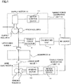
- FIG. 1 is a schematic diagram of an embodiment of the present invention.
- a wire electrode 8 is pulled out from a source bobbin (not shown), the wire electrode 8 passes through an upper wire guide 6 and a lower wire guide 7 while being pressed against a supply roller 4 by a pinch roller 5, and the wire electrode 8 is sandwiched between winding rollers 9 and 9 and is sent out.
- a workpiece W is electric discharge machined between the upper wire guide 6 and the lower wire guide 7.
- the supply roller 4 is driven by a supply motor 12, and the winding rollers 9 are driven by a winding motor 13.
- Driving states of the supply motor 12 and the winding motor 13 are controlled through motor control devices 11 and 14 based on commands from an NC device (numerical controller) 1, and a running state and a tensile force of the wire electrode are controlled.
- the supply roller 4, the pinch roller 5, the supply motor 12, the motor control device 11, the winding rollers 9 and 9, the winding motor 13 and the motor control device 14 configure a tensile force generating unit 10 which gives a tensile force to the wire electrode 8.
- a tensile force detector 2 for detecting a tensile force of the wire electrode 8 in a zone between the supply roller 4 and the winding rollers 9 including an electric discharge machining region.
- the tensile force detector 2 detects a tensile force of the wire electrode 8 and outputs the same to a calibrating unit 3.
- the calibrating unit 3 is a unit for calibrating the tensile force detector 2, and the calibrating unit 3 corrects a tensile force detected by the tensile force detector 2 and outputs the corrected detected tensile force to the NC device 1.
- the NC device 1 controls speed or torque of the supply motor 12 and the winding motor 13 as in the conventional technique based on a command tensile force and the corrected detected tensile force which is input, thereby performing the feedback control such that the tensile force of the wire electrode 8 matches with the command tensile force.
- the present invention is the same as the conventional technique in that a tensile force of a wire electrode is detected using a tensile force detector, and feedback control is performed such that the tensile force of the wire electrode 8 matches with the command tensile force, but the invention is characterized in that the calibrating unit 3 which corrects output of the tensile force detector 2 is added, and a deviation amount of the output of the tensile force detector 2 is corrected.
- the calibrating unit 3 is provided outside the NC device 1 in the embodiment shown in FIG. 1 , the calibrating unit 3 may be provided in the NC device 1 and a processor of the NC device 1 may carry out the operation and the processing as the calibrating unit 3.
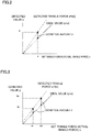
- FIGS. 2 to 5 are explanatory diagrams of first to fourth aspects of a calibrating operational principle carried out by the calibrating unit 3, and are explanatory diagrams of a method for obtaining a detected deviation amount between a detected tensile force and an ideal value (actual tensile force) as a function with respect to a set tensile force.
- a detected tensile force y which is output from the tensile force detector 2 is corrected with the detected deviation amount d obtained by a set (command) tensile force x, and the corrected detected tensile force is output. According to this, the detected deviation of the tensile force detector 2 is corrected and a precise tensile force can be detected.
- This first aspect is applied to a tensile force detector in which when the set tensile force (tensile force of wire electrode) x is 0, a detected tensile force y of the tensile force detector 2 is 0, and a detected tensile force y of the tensile force detector 2 is simply proportional to a set tensile force (expected value as actual tensile force, ideal value) x.
- this detected tensile force y is b.
- FIG. 3 is applied to a tensile force detector in which a detected tensile force y is simply proportional to a set tensile force (actual tensile force) x, but a detected tensile force y of the tensile force detector 2 is not 0 when a set tensile force x is 0.
- the set tensile forces x are set to a 1 and a 2 , these tensile forces are applied to the wire electrode 8, respectively, and detected tensile forces y which are output from the tensile force detector 2 are obtained as b 1 and b 2 .
- tensile forces y are detected by the tensile force detector 2 for a plurality of set tensile forces x, and a relational expression f(x) of an approximation straight line is obtained using approximate means such as a least-square method from sequence of points of the detection point (x, y).
- a relational expression f(x) in which these points are connected to one another through a smooth curved line may be obtained.
- a relational expression f(x) of a detected tensile force with respect to the set tensile force may be obtained by controlling speed or torque of the supply motor 12 and the winding motor 13, and by continuously detecting output y of the tensile force detector while continuously changing the tensile force x to be given to the wire electrode.
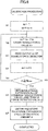
- FIG. 6 is a flowchart showing an algorithm of calibration processing of the tensile force detector carried out by a processor of the calibrating unit 3, or by the processor of the NC device 1 when the calibrating unit is configured in the NC device 1.
- an index n is set to "1"
- a set tensile force value x n which is obtained by adding a predetermined amount a to a last command tensile force value x n-1 is obtained
- the set tensile force value x n is output to the tensile force generating unit 10 (step S2).
- the tensile force generating unit 10 drives and controls the supply motor 12 and the winding motor 13 through the motor control devices 11 and 14 in the same manner as that of the conventional technique, and the wire electrode 8 is made to generate the commanded tensile force x n .
- the wire electrode when the wire electrode is made to generate a tensile force by controlling the speeds of the supply motor 12 and the winding motor 13, speed of the winding roller 9 to wind the wire electrode and speeds of the supply roller 4 and the pinch roller 5 to send out the wire electrode are differentiated from each other, and the wire electrode is made to generate the commanded tensile force x n based on this speed difference.
- the wire electrode When the wire electrode is made to generate a command tensile force by torques of the supply motor 12 and the winding motor 13, a tensile force is generated by controlling the torques of the supply motor 12 and the winding motor 13. In this case, the wire electrode may run or stop running.
- a detected tensile force value y n of output of the tensile force detector 2 is read (step S3), 1 is added to the index n (step S4), it is determined whether the value of the index n is equal to or greater than the number N max which is set for obtaining data (step S5), and if the value of the index n is not equal to or greater than the number N max , the procedure returns to step S2, processing in steps S2 to S5 is executed until the value of the index n reaches the set number N max and thereafter, the procedure is shifted to step S6.
- the number N max for obtained the data is set to "1”
- the relational expression f(x) of the set tensile force x shown in the first expression and the detected tensile force y is obtained by a command tensile force value x 1 (a in FIG. 2 ) and a tensile force detected value y1 (b in FIG. 2 ) which is detected at that time, and a function expression of the set tensile force x which is for obtaining a deviation amount d shown in the second expression is stored.
- the number N max for obtaining the data is set to "2"
- the relational expression f(x) of the set tensile force value x shown in the third expression and the tensile force detected value y is obtained by the commanded set tensile force value x 1 , x 2 (a 1 , a 2 in FIG. 2 ) and the tensile force detected value y 1 , y 2 (b 1 , b 2 in FIG. 2 ) detected at that time, and an expression for obtaining the deviation amount d shown in the expression 4 is stored.
- the relational expression f(x) of the set tensile force value x and the tensile force detected value y is obtained by an approximate method such as a least-square method from sequence of points ((x 1 , y 1 ), (x 2 , y 2 ), ... (x Nmax , y Nmax )) which is a combination of commanded set tensile force values x 1 , x 2 ... x Nmax and detected tensile force detected values y 1 , y 2 ... y Nmax .
- curve approximation is executed from sequence of points ((x 1 , y 1 ), (x 2 , y 2 ) ... (x Nmax , y Nmax )) which is a combination of the set tensile force value and the tensile force detected value, and the relational expression f(x) is obtained.
- FIG. 7 is a flowchart showing an algorithm of processing for obtaining a tensile force value obtained by calibrating and correcting the tensile force detector when the electric discharge machining is carried out.
- the processor of the calibrating unit 3 executes the processing shown in FIG. 7 every predetermined cycle, a tensile force of the wire electrode 8 detected by the tensile force detector 2 is corrected with a detected deviation amount d obtained by calibrating, and a corrected tensile force detected value is obtained.
- a detected tensile force y r which is output of the tensile force detector 2 is read (step T3), a detected tensile force Y r is obtained by subtracting a detected deviation amount (correction amount) d r from the detected tensile force y r (step T4), and the detection processing of a tensile force is completed.
- the NC device 1 drives and controls the tensile force generating unit 10 based on the corrected detected value Y r obtained as described above in the same manner as that of the conventional technique, and feedback control is executed such that a tensile force of the wire electrode 8 matches with the set tensile force value.
- the detected deviation amount (correction amount) d r with respect to the set tensile force value is changed unless this set value is not changed. Therefore, it is possible to employ such a configuration that the processing in steps T1 and T2 is carried out whenever the set value of the tensile force value is changed to obtain the detected deviation amount d r with respect to the set tensile force value, and only the processing in steps T3 and T4 is carried out when detecting a tensile force of the wire electrode.
- the calibration processing of the tensile force detector for obtaining the detected deviation amount d of the tensile force detector as the expression expressing as a function of the set tensile force is carried out based on the command tensile force which is set in the wire electrode and the detected tensile force which is output from the tensile force detector, the detected deviation amount with respect to the set tensile force which is set when the electric discharge machining is carried out is obtained by the function expression of the detected deviation amount, and the output of the tensile force detector is corrected. Therefore, it is possible to easily calibrate the tensile force detector.
- the calibration processing shown in FIG. 6 should be again executed, and a function expression for obtaining a new deviation amount should be obtained.
- the calibration processing may be carried out in a state where the sending operation of the wire electrode is stopped or in a state where the sending operation is not stopped.
- thermometer To facilitate the calibration processing associated with temperature change, it is possible to employ such a configuration that a thermometer is provided, temperature detected by the thermometer is stored in the NC device 1 or the calibrating unit 3 when the calibration processing is carried out, and when temperature is changed from the stored temperature more than a predetermined value, a signal inducing the calibration processing may be output (display on display screen for example). Furthermore, when temperature is changed from the stored temperature more than the predetermined value, the calibration processing shown in FIG. 6 may be executed automatically.
- the relational expression f(x) of the set tensile force x and the tensile force detection y is obtained
- detected tensile force y r is corrected.
Landscapes
- Engineering & Computer Science (AREA)
- Mechanical Engineering (AREA)
- Chemical & Material Sciences (AREA)
- Chemical Kinetics & Catalysis (AREA)
- Electrochemistry (AREA)
- Electrical Discharge Machining, Electrochemical Machining, And Combined Machining (AREA)
- Human Computer Interaction (AREA)
- Manufacturing & Machinery (AREA)
- Physics & Mathematics (AREA)
- General Physics & Mathematics (AREA)
- Automation & Control Theory (AREA)
Claims (6)
- Drahterosionsmaschine, umfassend:eine NC-Vorrichtung (1);eine Zugkrafterzeugungseinheit (10), um eine Zugkraft auf eine Drahtelektrode (8) auszuüben; undeinen Zugkraftdetektor (2) zum Erfassen einer Zugkraft der Drahtelektrode (8), wobei die erfasste Zugkraft, die durch den Zugkraftdetektor (2) erfasst wird, rückgekoppelt wird, um eine Rückkopplungssteuerung der Zugkraft der Drahtelektrode (8) auszuführen, so dass die Zugkraft gleich einer Sollzugkraft wird, dadurch gekennzeichnet, dassdie Drahterosionsmaschine weiter eine Kalibrierungseinheit (3) enthält, die eine Kalibrierung ausführt, um ein erfasstes Maß an Abweichung des Zugkraftdetektors (2) basierend auf der Sollzugkraft und einer Zugkraft, die durch den Zugkraftdetektor (2) erfasst wird, wenn die Sollzugkraft ausgeübt wird, zu erhalten, wobei die Kalibrierungseinheit (3) einen Ausgang des Zugkraftdetektors (2) um das erfasste Maß an Abweichung korrigiert, das durch die Kalibrierung erhalten wird, unddie Drahterosionsmaschine eine Funktion aufweist, einen erfassten Wert einer Zugkraft zu korrigieren, um eine Rückkopplungssteuerung der Zugkraft der Drahtelektrode (8) basierend auf einer korrigierten erfassten Zugkraft, die durch Korrigieren der erfassten Zugkraft des Zugkraftdetektors durch die Kalibrierungseinheit (3) erhalten wird, auszuführen,wobei beim Kalibrieren der Kalibrierungseinheit (3) das erfasste Maß an Abweichung erhalten und als Funktion der Sollzugkraft gespeichert wird, und wenn die Drahterosionsbearbeitung ausgeführt wird, die Kalibrierungseinheit (3) ein erfasstes Maß an Abweichung in Bezug auf einen Wert der Zugkraft erhält, die durch die Funktion einzustellen ist, und die erfasste Zugkraft, die durch den Zugkraftdetektor (2) erfasst wird, mit dem erfassten Maß an Abweichung als eine korrigierte erfasste Zugkraft korrigiert wird.
- Drahterosionsmaschine mit einer Funktion, einen erfassten Wert einer Zugkraft zu korrigieren, nach Anspruch 1, wobei beim Kalibrieren der Kalibrierungseinheit (3) eine Abfolge von Punkten einer Kombination mehrerer Sollzugkräfte und einer Zugkraft, die durch den Zugkraftdetektor (2) erfasst wird, wenn die Sollzugkräfte ausgeübt werden, gespeichert wird und wenn die Drahterosionsbearbeitung ausgeführt wird, ein erfasstes Maß an Abweichung in Bezug auf eine Zugkraft, die eingestellt wird, wenn eine Bearbeitung ausgeführt wird, durch die Abfolge von Punkten einer Kombination der gespeicherten Sollzugkraft und der erfassten Zugkraft erhalten wird, und die erfasste Zugkraft, die durch den Zugkraftdetektor (2) erfasst wird, mit dem erfassten Maß an Abweichung als eine korrigierte erfasste Zugkraft korrigiert wird.
- Drahterosionsmaschine mit einer Funktion, einen erfassten Wert einer Zugkraft zu korrigieren, nach einem der Ansprüche 1 oder 2, wobei die Zugkrafterzeugungseinheit (10) ein Motor (12) ist, der eine Antriebskraft auf die Drahtelektrode (8) ausübt.
- Drahterosionsmaschine mit einer Funktion, einen erfassten Wert einer Zugkraft zu korrigieren, nach einem der Ansprüche 1 bis 3, wobei die Kalibrierung des Zugkraftdetektors (2) ausgeführt wird, wenn ein Sendebetrieb der Drahtelektrode (8) gestoppt ist.
- Drahterosionsmaschine mit einer Funktion, einen erfassten Wert einer Zugkraft zu korrigieren, nach einem der Ansprüche 1 bis 3, wobei die Kalibrierung des Zugkraftdetektors (2) ausgeführt wird, wenn die Drahtelektrode (8) ausgesendet wird.
- Drahterosionsmaschine mit einer Funktion, einen erfassten Wert einer Zugkraft zu korrigieren, nach einem der Ansprüche 1 bis 5, wobei die Kalibrierung des Zugkraftdetektors (2) automatisch ausgeführt wird, wenn Temperatur um ein bestimmtes Maß geändert wird oder Informationen, die eine Kalibrierung des Zugkraftdetektors (2) veranlassen, angezeigt werden.
Applications Claiming Priority (1)
| Application Number | Priority Date | Filing Date | Title |
|---|---|---|---|
| JP2015044991A JP6133917B2 (ja) | 2015-03-06 | 2015-03-06 | 張力の検出値を補正する機能を有するワイヤ放電加工機 |
Publications (2)
| Publication Number | Publication Date |
|---|---|
| EP3064302A1 EP3064302A1 (de) | 2016-09-07 |
| EP3064302B1 true EP3064302B1 (de) | 2020-04-22 |
Family
ID=55456717
Family Applications (1)
| Application Number | Title | Priority Date | Filing Date |
|---|---|---|---|
| EP16158750.6A Active EP3064302B1 (de) | 2015-03-06 | 2016-03-04 | Drahterosionsmaschine mit funktion zur korrektur des messwerts der drahtspannung |
Country Status (5)
| Country | Link |
|---|---|
| US (1) | US10105776B2 (de) |
| EP (1) | EP3064302B1 (de) |
| JP (1) | JP6133917B2 (de) |
| KR (1) | KR101904598B1 (de) |
| CN (1) | CN105935821B (de) |
Families Citing this family (6)
| Publication number | Priority date | Publication date | Assignee | Title |
|---|---|---|---|---|
| JP6444959B2 (ja) * | 2016-11-01 | 2018-12-26 | ファナック株式会社 | ワイヤ放電加工機 |
| CN108367372B (zh) * | 2016-11-10 | 2021-01-26 | 西部电机株式会社 | 张力控制方法以及放电加工装置 |
| KR102025770B1 (ko) | 2019-03-15 | 2019-09-26 | 변영일 | 와이어 방전 가공기 및 이를 이용한 절삭 공구 제조 장치 |
| CN109967809B (zh) * | 2019-04-09 | 2020-12-11 | 南京航空航天大学 | 一种电火花线切割电极丝张力检测及lcd图像显示装置 |
| JP7451191B2 (ja) * | 2020-01-28 | 2024-03-18 | 住友重機械工業株式会社 | 制御装置およびロール・ツー・ロール搬送システム |
| CN114414142A (zh) * | 2022-01-25 | 2022-04-29 | 苏州汇川控制技术有限公司 | 张力传感器的校准方法、装置、校准设备以及介质 |
Family Cites Families (28)
| Publication number | Priority date | Publication date | Assignee | Title |
|---|---|---|---|---|
| CH620620A5 (de) * | 1978-05-29 | 1980-12-15 | Charmilles Sa Ateliers | |
| JPS59152021A (ja) * | 1983-02-15 | 1984-08-30 | Fanuc Ltd | ワイヤカツト放電加工装置 |
| JPS59152022A (ja) * | 1983-02-15 | 1984-08-30 | Fanuc Ltd | ワイヤ電極張力制御方式 |
| JPS60177824A (ja) * | 1984-02-21 | 1985-09-11 | Inoue Japax Res Inc | ワイヤ電極の判定装置 |
| JPS63127830A (ja) * | 1986-11-17 | 1988-05-31 | Hoden Seimitsu Kako Kenkyusho Ltd | ワイヤ放電加工装置 |
| JPS63256316A (ja) * | 1987-04-13 | 1988-10-24 | Mitsubishi Electric Corp | ワイヤ放電加工装置 |
| JPH01199726A (ja) * | 1988-02-03 | 1989-08-11 | Fanuc Ltd | ワイヤ張力,断線検出制御装置 |
| JP2692386B2 (ja) * | 1991-01-17 | 1997-12-17 | 三菱電機株式会社 | ワイヤ放電加工装置 |
| JPH05312657A (ja) * | 1992-05-08 | 1993-11-22 | I N R Kenkyusho:Kk | ワイヤ張力測定装置 |
| JPH07328849A (ja) * | 1994-06-13 | 1995-12-19 | Okuma Mach Works Ltd | ワイヤ電極の張力と送り速度の制御方法及びその装置 |
| JP3416514B2 (ja) | 1997-03-07 | 2003-06-16 | 株式会社ソディック | ワイヤ放電加工装置に於けるワイヤ電極の張力制御方法及びその装置 |
| WO1998039128A1 (fr) * | 1997-03-07 | 1998-09-11 | Sodick Co., Ltd. | Systeme et procede d'usinage par decharge pour le decoupage par fil-electrode |
| JP3883690B2 (ja) * | 1998-03-04 | 2007-02-21 | 株式会社ソディック | ワイヤ放電加工機のワイヤ電極張力制御装置及びその方法並びに張力制御回路のフィルタの決定及び調整設定方法 |
| JP3696431B2 (ja) * | 1999-04-08 | 2005-09-21 | 株式会社ミツトヨ | 一次元測定機 |
| JP2002340711A (ja) * | 2001-05-18 | 2002-11-27 | Mitsubishi Electric Corp | ワイヤ電極張力センサおよびワイヤ放電加工機 |
| JP2002346840A (ja) * | 2001-05-29 | 2002-12-04 | Hitachi Via Mechanics Ltd | ワイヤ放電加工装置 |
| JP4230157B2 (ja) | 2002-03-19 | 2009-02-25 | 三菱電機株式会社 | ワイヤ放電加工機のワイヤ張力制御装置 |
| JP4463534B2 (ja) * | 2003-12-02 | 2010-05-19 | 住友重機械工業株式会社 | 成形装置、成形品及び金型相対距離計測方法 |
| JP4168076B2 (ja) | 2007-03-08 | 2008-10-22 | ファナック株式会社 | ワイヤ電極張力制御機能を有するワイヤカット放電加工機 |
| JP2009180523A (ja) * | 2008-01-29 | 2009-08-13 | Toshiba Corp | 角度検出装置の角度補正曲線取得方法及び角度検出装置 |
| CN101670472B (zh) * | 2008-09-12 | 2011-06-08 | 财团法人工业技术研究院 | 线切割电化学放电加工进给控制方法与装置 |
| JP2010179377A (ja) | 2009-02-03 | 2010-08-19 | Fanuc Ltd | ワイヤ電極の残量検出機能を有するワイヤカット放電加工機 |
| WO2011067877A1 (ja) * | 2009-12-01 | 2011-06-09 | 株式会社フジキン | 圧力式流量制御装置 |
| JP5088975B2 (ja) * | 2010-10-19 | 2012-12-05 | 株式会社ソディック | ワイヤ放電加工装置 |
| JP2014028463A (ja) * | 2012-07-31 | 2014-02-13 | Ricoh Co Ltd | 画像形成装置、パターン位置検出方法、画像形成システム、印刷物の生産方法 |
| DE112012007076B4 (de) * | 2012-10-30 | 2023-09-07 | Mitsubishi Electric Corporation | Drahtfunkenerosion-Bearbeitungsvorrichtung, Bearbeitungssteuervorrichtung und SPEICHERMEDIUM MIT ZUGEHÖRIGEM BEARBEITUNGSSTEUERPROGRAMM |
| CN203254023U (zh) * | 2013-01-30 | 2013-10-30 | 南通伊阳精密机械有限公司 | 线切割机床张力可调装置 |
| JP2014200864A (ja) * | 2013-04-02 | 2014-10-27 | ファナック株式会社 | ワイヤ電極張力制御機能を有するワイヤ放電加工機 |
-
2015
- 2015-03-06 JP JP2015044991A patent/JP6133917B2/ja active Active
-
2016
- 2016-03-03 KR KR1020160025879A patent/KR101904598B1/ko active IP Right Grant
- 2016-03-04 EP EP16158750.6A patent/EP3064302B1/de active Active
- 2016-03-04 CN CN201610124944.9A patent/CN105935821B/zh active Active
- 2016-03-05 US US15/062,106 patent/US10105776B2/en active Active
Non-Patent Citations (1)
| Title |
|---|
| None * |
Also Published As
| Publication number | Publication date |
|---|---|
| KR20160108209A (ko) | 2016-09-19 |
| CN105935821A (zh) | 2016-09-14 |
| KR101904598B1 (ko) | 2018-10-04 |
| JP2016163923A (ja) | 2016-09-08 |
| US20160263690A1 (en) | 2016-09-15 |
| JP6133917B2 (ja) | 2017-05-24 |
| EP3064302A1 (de) | 2016-09-07 |
| US10105776B2 (en) | 2018-10-23 |
| CN105935821B (zh) | 2018-11-02 |
Similar Documents
| Publication | Publication Date | Title |
|---|---|---|
| EP3064302B1 (de) | Drahterosionsmaschine mit funktion zur korrektur des messwerts der drahtspannung | |
| US10259118B2 (en) | Robot system having function of simplifying teaching operation and improving operating performance by learning | |
| US9829877B2 (en) | Servo control apparatus having function of displaying adjustment state in online automatic adjustment to control system | |
| US10254741B2 (en) | Robot apparatus having learning function | |
| US9782898B2 (en) | Robot controller for avoiding problem regarding robot at the time of emergency stop | |
| JP5889497B1 (ja) | ローラ間搬送制御装置 | |
| US10029873B2 (en) | Apparatus for controlling conveyance between rollers | |
| KR101701646B1 (ko) | 압연 제어 장치, 압연 제어 방법 및 기록매체 | |
| US8836528B2 (en) | Data display device for machine tool for displaying information based on specified condition | |
| TWI549895B (zh) | 捲筒間搬送控制裝置 | |
| EP3025798B1 (de) | Walzsteuerungsvorrichtung und walzsteuerungsverfahren | |
| JP2008079441A (ja) | モータ制御装置およびモータ制御装置を含む制御機器 | |
| TW201221457A (en) | Method and arrangement in connection with winder drive | |
| JP2008174355A (ja) | 張力制御装置及び張力制御方法 | |
| US20190151971A1 (en) | Tension control method and electrical discharge machining apparatus | |
| JP2013216450A (ja) | 巻出ロールの制御装置及びその制御方法 | |
| EP2822176B1 (de) | Vektorsteuerungsvorrichtung eines induktionsmotors | |
| JPH061533A (ja) | 巻取・巻出機の張力制御装置 | |
| WO2018193649A1 (ja) | 電動機制御装置 | |
| WO2018158828A1 (ja) | シート材生産ラインの数学モデル算出装置および制御装置 | |
| JP6189695B2 (ja) | ワイヤ送給装置 | |
| JPH06261574A (ja) | サーボモータの制御装置 | |
| JP6292731B1 (ja) | 張力制御方法及び放電加工装置 | |
| JP2014204565A (ja) | 電動機駆動装置及び電動機駆動方法 | |
| JPH09323851A (ja) | 巻取装置 |
Legal Events
| Date | Code | Title | Description |
|---|---|---|---|
| PUAI | Public reference made under article 153(3) epc to a published international application that has entered the european phase |
Free format text: ORIGINAL CODE: 0009012 |
|
| AK | Designated contracting states |
Kind code of ref document: A1 Designated state(s): AL AT BE BG CH CY CZ DE DK EE ES FI FR GB GR HR HU IE IS IT LI LT LU LV MC MK MT NL NO PL PT RO RS SE SI SK SM TR |
|
| AX | Request for extension of the european patent |
Extension state: BA ME |
|
| STAA | Information on the status of an ep patent application or granted ep patent |
Free format text: STATUS: REQUEST FOR EXAMINATION WAS MADE |
|
| 17P | Request for examination filed |
Effective date: 20170306 |
|
| RBV | Designated contracting states (corrected) |
Designated state(s): AL AT BE BG CH CY CZ DE DK EE ES FI FR GB GR HR HU IE IS IT LI LT LU LV MC MK MT NL NO PL PT RO RS SE SI SK SM TR |
|
| GRAP | Despatch of communication of intention to grant a patent |
Free format text: ORIGINAL CODE: EPIDOSNIGR1 |
|
| STAA | Information on the status of an ep patent application or granted ep patent |
Free format text: STATUS: GRANT OF PATENT IS INTENDED |
|
| INTG | Intention to grant announced |
Effective date: 20200115 |
|
| GRAS | Grant fee paid |
Free format text: ORIGINAL CODE: EPIDOSNIGR3 |
|
| GRAA | (expected) grant |
Free format text: ORIGINAL CODE: 0009210 |
|
| STAA | Information on the status of an ep patent application or granted ep patent |
Free format text: STATUS: THE PATENT HAS BEEN GRANTED |
|
| AK | Designated contracting states |
Kind code of ref document: B1 Designated state(s): AL AT BE BG CH CY CZ DE DK EE ES FI FR GB GR HR HU IE IS IT LI LT LU LV MC MK MT NL NO PL PT RO RS SE SI SK SM TR |
|
| REG | Reference to a national code |
Ref country code: CH Ref legal event code: EP Ref country code: CH Ref legal event code: NV Representative=s name: DR. LUSUARDI AG, CH |
|
| REG | Reference to a national code |
Ref country code: IE Ref legal event code: FG4D |
|
| REG | Reference to a national code |
Ref country code: DE Ref legal event code: R096 Ref document number: 602016034352 Country of ref document: DE |
|
| REG | Reference to a national code |
Ref country code: AT Ref legal event code: REF Ref document number: 1259428 Country of ref document: AT Kind code of ref document: T Effective date: 20200515 |
|
| REG | Reference to a national code |
Ref country code: LT Ref legal event code: MG4D |
|
| REG | Reference to a national code |
Ref country code: NL Ref legal event code: MP Effective date: 20200422 |
|
| PG25 | Lapsed in a contracting state [announced via postgrant information from national office to epo] |
Ref country code: SE Free format text: LAPSE BECAUSE OF FAILURE TO SUBMIT A TRANSLATION OF THE DESCRIPTION OR TO PAY THE FEE WITHIN THE PRESCRIBED TIME-LIMIT Effective date: 20200422 Ref country code: LT Free format text: LAPSE BECAUSE OF FAILURE TO SUBMIT A TRANSLATION OF THE DESCRIPTION OR TO PAY THE FEE WITHIN THE PRESCRIBED TIME-LIMIT Effective date: 20200422 Ref country code: PT Free format text: LAPSE BECAUSE OF FAILURE TO SUBMIT A TRANSLATION OF THE DESCRIPTION OR TO PAY THE FEE WITHIN THE PRESCRIBED TIME-LIMIT Effective date: 20200824 Ref country code: NL Free format text: LAPSE BECAUSE OF FAILURE TO SUBMIT A TRANSLATION OF THE DESCRIPTION OR TO PAY THE FEE WITHIN THE PRESCRIBED TIME-LIMIT Effective date: 20200422 Ref country code: NO Free format text: LAPSE BECAUSE OF FAILURE TO SUBMIT A TRANSLATION OF THE DESCRIPTION OR TO PAY THE FEE WITHIN THE PRESCRIBED TIME-LIMIT Effective date: 20200722 Ref country code: GR Free format text: LAPSE BECAUSE OF FAILURE TO SUBMIT A TRANSLATION OF THE DESCRIPTION OR TO PAY THE FEE WITHIN THE PRESCRIBED TIME-LIMIT Effective date: 20200723 Ref country code: IS Free format text: LAPSE BECAUSE OF FAILURE TO SUBMIT A TRANSLATION OF THE DESCRIPTION OR TO PAY THE FEE WITHIN THE PRESCRIBED TIME-LIMIT Effective date: 20200822 Ref country code: FI Free format text: LAPSE BECAUSE OF FAILURE TO SUBMIT A TRANSLATION OF THE DESCRIPTION OR TO PAY THE FEE WITHIN THE PRESCRIBED TIME-LIMIT Effective date: 20200422 |
|
| REG | Reference to a national code |
Ref country code: AT Ref legal event code: MK05 Ref document number: 1259428 Country of ref document: AT Kind code of ref document: T Effective date: 20200422 |
|
| PG25 | Lapsed in a contracting state [announced via postgrant information from national office to epo] |
Ref country code: BG Free format text: LAPSE BECAUSE OF FAILURE TO SUBMIT A TRANSLATION OF THE DESCRIPTION OR TO PAY THE FEE WITHIN THE PRESCRIBED TIME-LIMIT Effective date: 20200722 Ref country code: HR Free format text: LAPSE BECAUSE OF FAILURE TO SUBMIT A TRANSLATION OF THE DESCRIPTION OR TO PAY THE FEE WITHIN THE PRESCRIBED TIME-LIMIT Effective date: 20200422 Ref country code: RS Free format text: LAPSE BECAUSE OF FAILURE TO SUBMIT A TRANSLATION OF THE DESCRIPTION OR TO PAY THE FEE WITHIN THE PRESCRIBED TIME-LIMIT Effective date: 20200422 Ref country code: LV Free format text: LAPSE BECAUSE OF FAILURE TO SUBMIT A TRANSLATION OF THE DESCRIPTION OR TO PAY THE FEE WITHIN THE PRESCRIBED TIME-LIMIT Effective date: 20200422 |
|
| PG25 | Lapsed in a contracting state [announced via postgrant information from national office to epo] |
Ref country code: AL Free format text: LAPSE BECAUSE OF FAILURE TO SUBMIT A TRANSLATION OF THE DESCRIPTION OR TO PAY THE FEE WITHIN THE PRESCRIBED TIME-LIMIT Effective date: 20200422 |
|
| REG | Reference to a national code |
Ref country code: DE Ref legal event code: R082 Ref document number: 602016034352 Country of ref document: DE Representative=s name: HL KEMPNER PATENTANWAELTE, SOLICITORS (ENGLAND, DE Ref country code: DE Ref legal event code: R082 Ref document number: 602016034352 Country of ref document: DE Representative=s name: HL KEMPNER PATENTANWALT, RECHTSANWALT, SOLICIT, DE |
|
| REG | Reference to a national code |
Ref country code: DE Ref legal event code: R097 Ref document number: 602016034352 Country of ref document: DE |
|
| PG25 | Lapsed in a contracting state [announced via postgrant information from national office to epo] |
Ref country code: RO Free format text: LAPSE BECAUSE OF FAILURE TO SUBMIT A TRANSLATION OF THE DESCRIPTION OR TO PAY THE FEE WITHIN THE PRESCRIBED TIME-LIMIT Effective date: 20200422 Ref country code: IT Free format text: LAPSE BECAUSE OF FAILURE TO SUBMIT A TRANSLATION OF THE DESCRIPTION OR TO PAY THE FEE WITHIN THE PRESCRIBED TIME-LIMIT Effective date: 20200422 Ref country code: CZ Free format text: LAPSE BECAUSE OF FAILURE TO SUBMIT A TRANSLATION OF THE DESCRIPTION OR TO PAY THE FEE WITHIN THE PRESCRIBED TIME-LIMIT Effective date: 20200422 Ref country code: ES Free format text: LAPSE BECAUSE OF FAILURE TO SUBMIT A TRANSLATION OF THE DESCRIPTION OR TO PAY THE FEE WITHIN THE PRESCRIBED TIME-LIMIT Effective date: 20200422 Ref country code: AT Free format text: LAPSE BECAUSE OF FAILURE TO SUBMIT A TRANSLATION OF THE DESCRIPTION OR TO PAY THE FEE WITHIN THE PRESCRIBED TIME-LIMIT Effective date: 20200422 Ref country code: EE Free format text: LAPSE BECAUSE OF FAILURE TO SUBMIT A TRANSLATION OF THE DESCRIPTION OR TO PAY THE FEE WITHIN THE PRESCRIBED TIME-LIMIT Effective date: 20200422 Ref country code: SM Free format text: LAPSE BECAUSE OF FAILURE TO SUBMIT A TRANSLATION OF THE DESCRIPTION OR TO PAY THE FEE WITHIN THE PRESCRIBED TIME-LIMIT Effective date: 20200422 Ref country code: DK Free format text: LAPSE BECAUSE OF FAILURE TO SUBMIT A TRANSLATION OF THE DESCRIPTION OR TO PAY THE FEE WITHIN THE PRESCRIBED TIME-LIMIT Effective date: 20200422 |
|
| PG25 | Lapsed in a contracting state [announced via postgrant information from national office to epo] |
Ref country code: SK Free format text: LAPSE BECAUSE OF FAILURE TO SUBMIT A TRANSLATION OF THE DESCRIPTION OR TO PAY THE FEE WITHIN THE PRESCRIBED TIME-LIMIT Effective date: 20200422 Ref country code: PL Free format text: LAPSE BECAUSE OF FAILURE TO SUBMIT A TRANSLATION OF THE DESCRIPTION OR TO PAY THE FEE WITHIN THE PRESCRIBED TIME-LIMIT Effective date: 20200422 |
|
| PLBE | No opposition filed within time limit |
Free format text: ORIGINAL CODE: 0009261 |
|
| STAA | Information on the status of an ep patent application or granted ep patent |
Free format text: STATUS: NO OPPOSITION FILED WITHIN TIME LIMIT |
|
| 26N | No opposition filed |
Effective date: 20210125 |
|
| PG25 | Lapsed in a contracting state [announced via postgrant information from national office to epo] |
Ref country code: SI Free format text: LAPSE BECAUSE OF FAILURE TO SUBMIT A TRANSLATION OF THE DESCRIPTION OR TO PAY THE FEE WITHIN THE PRESCRIBED TIME-LIMIT Effective date: 20200422 |
|
| PG25 | Lapsed in a contracting state [announced via postgrant information from national office to epo] |
Ref country code: MC Free format text: LAPSE BECAUSE OF FAILURE TO SUBMIT A TRANSLATION OF THE DESCRIPTION OR TO PAY THE FEE WITHIN THE PRESCRIBED TIME-LIMIT Effective date: 20200422 |
|
| GBPC | Gb: european patent ceased through non-payment of renewal fee |
Effective date: 20210304 |
|
| REG | Reference to a national code |
Ref country code: BE Ref legal event code: MM Effective date: 20210331 |
|
| PG25 | Lapsed in a contracting state [announced via postgrant information from national office to epo] |
Ref country code: LU Free format text: LAPSE BECAUSE OF NON-PAYMENT OF DUE FEES Effective date: 20210304 Ref country code: FR Free format text: LAPSE BECAUSE OF NON-PAYMENT OF DUE FEES Effective date: 20210331 Ref country code: IE Free format text: LAPSE BECAUSE OF NON-PAYMENT OF DUE FEES Effective date: 20210304 Ref country code: GB Free format text: LAPSE BECAUSE OF NON-PAYMENT OF DUE FEES Effective date: 20210304 |
|
| PG25 | Lapsed in a contracting state [announced via postgrant information from national office to epo] |
Ref country code: BE Free format text: LAPSE BECAUSE OF NON-PAYMENT OF DUE FEES Effective date: 20210331 |
|
| PG25 | Lapsed in a contracting state [announced via postgrant information from national office to epo] |
Ref country code: HU Free format text: LAPSE BECAUSE OF FAILURE TO SUBMIT A TRANSLATION OF THE DESCRIPTION OR TO PAY THE FEE WITHIN THE PRESCRIBED TIME-LIMIT; INVALID AB INITIO Effective date: 20160304 |
|
| PG25 | Lapsed in a contracting state [announced via postgrant information from national office to epo] |
Ref country code: CY Free format text: LAPSE BECAUSE OF FAILURE TO SUBMIT A TRANSLATION OF THE DESCRIPTION OR TO PAY THE FEE WITHIN THE PRESCRIBED TIME-LIMIT Effective date: 20200422 |
|
| PGFP | Annual fee paid to national office [announced via postgrant information from national office to epo] |
Ref country code: CH Payment date: 20230401 Year of fee payment: 8 |
|
| PG25 | Lapsed in a contracting state [announced via postgrant information from national office to epo] |
Ref country code: MK Free format text: LAPSE BECAUSE OF FAILURE TO SUBMIT A TRANSLATION OF THE DESCRIPTION OR TO PAY THE FEE WITHIN THE PRESCRIBED TIME-LIMIT Effective date: 20200422 |
|
| PGFP | Annual fee paid to national office [announced via postgrant information from national office to epo] |
Ref country code: DE Payment date: 20240130 Year of fee payment: 9 |