EP3050718B1 - Luftreifen und verfahren zu dessen herstellung - Google Patents
Luftreifen und verfahren zu dessen herstellung Download PDFInfo
- Publication number
- EP3050718B1 EP3050718B1 EP14855491.8A EP14855491A EP3050718B1 EP 3050718 B1 EP3050718 B1 EP 3050718B1 EP 14855491 A EP14855491 A EP 14855491A EP 3050718 B1 EP3050718 B1 EP 3050718B1
- Authority
- EP
- European Patent Office
- Prior art keywords
- ply
- band
- tire
- ply portion
- belt layer
- Prior art date
- Legal status (The legal status is an assumption and is not a legal conclusion. Google has not performed a legal analysis and makes no representation as to the accuracy of the status listed.)
- Active
Links
Images




Classifications
-
- B—PERFORMING OPERATIONS; TRANSPORTING
- B60—VEHICLES IN GENERAL
- B60C—VEHICLE TYRES; TYRE INFLATION; TYRE CHANGING; CONNECTING VALVES TO INFLATABLE ELASTIC BODIES IN GENERAL; DEVICES OR ARRANGEMENTS RELATED TO TYRES
- B60C9/00—Reinforcements or ply arrangement of pneumatic tyres
- B60C9/18—Structure or arrangement of belts or breakers, crown-reinforcing or cushioning layers
- B60C9/20—Structure or arrangement of belts or breakers, crown-reinforcing or cushioning layers built-up from rubberised plies each having all cords arranged substantially parallel
-
- B—PERFORMING OPERATIONS; TRANSPORTING
- B29—WORKING OF PLASTICS; WORKING OF SUBSTANCES IN A PLASTIC STATE IN GENERAL
- B29D—PRODUCING PARTICULAR ARTICLES FROM PLASTICS OR FROM SUBSTANCES IN A PLASTIC STATE
- B29D30/00—Producing pneumatic or solid tyres or parts thereof
- B29D30/06—Pneumatic tyres or parts thereof (e.g. produced by casting, moulding, compression moulding, injection moulding, centrifugal casting)
- B29D30/08—Building tyres
- B29D30/20—Building tyres by the flat-tyre method, i.e. building on cylindrical drums
- B29D30/30—Applying the layers; Guiding or stretching the layers during application
- B29D30/3028—Applying the layers; Guiding or stretching the layers during application by feeding a continuous band and winding it helically, i.e. the band is fed while being advanced along the drum axis, to form an annular element
-
- B—PERFORMING OPERATIONS; TRANSPORTING
- B29—WORKING OF PLASTICS; WORKING OF SUBSTANCES IN A PLASTIC STATE IN GENERAL
- B29D—PRODUCING PARTICULAR ARTICLES FROM PLASTICS OR FROM SUBSTANCES IN A PLASTIC STATE
- B29D30/00—Producing pneumatic or solid tyres or parts thereof
- B29D30/06—Pneumatic tyres or parts thereof (e.g. produced by casting, moulding, compression moulding, injection moulding, centrifugal casting)
- B29D30/70—Annular breakers
-
- B—PERFORMING OPERATIONS; TRANSPORTING
- B60—VEHICLES IN GENERAL
- B60C—VEHICLE TYRES; TYRE INFLATION; TYRE CHANGING; CONNECTING VALVES TO INFLATABLE ELASTIC BODIES IN GENERAL; DEVICES OR ARRANGEMENTS RELATED TO TYRES
- B60C15/00—Tyre beads, e.g. ply turn-up or overlap
- B60C15/04—Bead cores
-
- B—PERFORMING OPERATIONS; TRANSPORTING
- B60—VEHICLES IN GENERAL
- B60C—VEHICLE TYRES; TYRE INFLATION; TYRE CHANGING; CONNECTING VALVES TO INFLATABLE ELASTIC BODIES IN GENERAL; DEVICES OR ARRANGEMENTS RELATED TO TYRES
- B60C9/00—Reinforcements or ply arrangement of pneumatic tyres
- B60C9/02—Carcasses
-
- B—PERFORMING OPERATIONS; TRANSPORTING
- B60—VEHICLES IN GENERAL
- B60C—VEHICLE TYRES; TYRE INFLATION; TYRE CHANGING; CONNECTING VALVES TO INFLATABLE ELASTIC BODIES IN GENERAL; DEVICES OR ARRANGEMENTS RELATED TO TYRES
- B60C9/00—Reinforcements or ply arrangement of pneumatic tyres
- B60C9/18—Structure or arrangement of belts or breakers, crown-reinforcing or cushioning layers
- B60C9/1835—Rubber strips or cushions at the belt edges
-
- B—PERFORMING OPERATIONS; TRANSPORTING
- B60—VEHICLES IN GENERAL
- B60C—VEHICLE TYRES; TYRE INFLATION; TYRE CHANGING; CONNECTING VALVES TO INFLATABLE ELASTIC BODIES IN GENERAL; DEVICES OR ARRANGEMENTS RELATED TO TYRES
- B60C9/00—Reinforcements or ply arrangement of pneumatic tyres
- B60C9/18—Structure or arrangement of belts or breakers, crown-reinforcing or cushioning layers
- B60C9/20—Structure or arrangement of belts or breakers, crown-reinforcing or cushioning layers built-up from rubberised plies each having all cords arranged substantially parallel
- B60C9/2003—Structure or arrangement of belts or breakers, crown-reinforcing or cushioning layers built-up from rubberised plies each having all cords arranged substantially parallel characterised by the materials of the belt cords
- B60C9/2009—Structure or arrangement of belts or breakers, crown-reinforcing or cushioning layers built-up from rubberised plies each having all cords arranged substantially parallel characterised by the materials of the belt cords comprising plies of different materials
-
- B—PERFORMING OPERATIONS; TRANSPORTING
- B60—VEHICLES IN GENERAL
- B60C—VEHICLE TYRES; TYRE INFLATION; TYRE CHANGING; CONNECTING VALVES TO INFLATABLE ELASTIC BODIES IN GENERAL; DEVICES OR ARRANGEMENTS RELATED TO TYRES
- B60C9/00—Reinforcements or ply arrangement of pneumatic tyres
- B60C9/18—Structure or arrangement of belts or breakers, crown-reinforcing or cushioning layers
- B60C9/20—Structure or arrangement of belts or breakers, crown-reinforcing or cushioning layers built-up from rubberised plies each having all cords arranged substantially parallel
- B60C9/22—Structure or arrangement of belts or breakers, crown-reinforcing or cushioning layers built-up from rubberised plies each having all cords arranged substantially parallel the plies being arranged with all cords disposed along the circumference of the tyre
- B60C9/2204—Structure or arrangement of belts or breakers, crown-reinforcing or cushioning layers built-up from rubberised plies each having all cords arranged substantially parallel the plies being arranged with all cords disposed along the circumference of the tyre obtained by circumferentially narrow strip winding
-
- B—PERFORMING OPERATIONS; TRANSPORTING
- B29—WORKING OF PLASTICS; WORKING OF SUBSTANCES IN A PLASTIC STATE IN GENERAL
- B29D—PRODUCING PARTICULAR ARTICLES FROM PLASTICS OR FROM SUBSTANCES IN A PLASTIC STATE
- B29D30/00—Producing pneumatic or solid tyres or parts thereof
- B29D30/06—Pneumatic tyres or parts thereof (e.g. produced by casting, moulding, compression moulding, injection moulding, centrifugal casting)
- B29D30/08—Building tyres
- B29D30/20—Building tyres by the flat-tyre method, i.e. building on cylindrical drums
- B29D30/30—Applying the layers; Guiding or stretching the layers during application
- B29D2030/3064—Details, accessories and auxiliary operations not otherwise provided for
- B29D2030/3078—Details, accessories and auxiliary operations not otherwise provided for the layers being applied being substantially continuous, i.e. not being cut before the application step
-
- B—PERFORMING OPERATIONS; TRANSPORTING
- B60—VEHICLES IN GENERAL
- B60C—VEHICLE TYRES; TYRE INFLATION; TYRE CHANGING; CONNECTING VALVES TO INFLATABLE ELASTIC BODIES IN GENERAL; DEVICES OR ARRANGEMENTS RELATED TO TYRES
- B60C9/00—Reinforcements or ply arrangement of pneumatic tyres
- B60C9/18—Structure or arrangement of belts or breakers, crown-reinforcing or cushioning layers
- B60C9/1835—Rubber strips or cushions at the belt edges
- B60C2009/1842—Width or thickness of the strips or cushions
-
- B—PERFORMING OPERATIONS; TRANSPORTING
- B60—VEHICLES IN GENERAL
- B60C—VEHICLE TYRES; TYRE INFLATION; TYRE CHANGING; CONNECTING VALVES TO INFLATABLE ELASTIC BODIES IN GENERAL; DEVICES OR ARRANGEMENTS RELATED TO TYRES
- B60C9/00—Reinforcements or ply arrangement of pneumatic tyres
- B60C9/18—Structure or arrangement of belts or breakers, crown-reinforcing or cushioning layers
- B60C9/20—Structure or arrangement of belts or breakers, crown-reinforcing or cushioning layers built-up from rubberised plies each having all cords arranged substantially parallel
- B60C2009/2012—Structure or arrangement of belts or breakers, crown-reinforcing or cushioning layers built-up from rubberised plies each having all cords arranged substantially parallel with particular configuration of the belt cords in the respective belt layers
-
- B—PERFORMING OPERATIONS; TRANSPORTING
- B60—VEHICLES IN GENERAL
- B60C—VEHICLE TYRES; TYRE INFLATION; TYRE CHANGING; CONNECTING VALVES TO INFLATABLE ELASTIC BODIES IN GENERAL; DEVICES OR ARRANGEMENTS RELATED TO TYRES
- B60C9/00—Reinforcements or ply arrangement of pneumatic tyres
- B60C9/18—Structure or arrangement of belts or breakers, crown-reinforcing or cushioning layers
- B60C9/20—Structure or arrangement of belts or breakers, crown-reinforcing or cushioning layers built-up from rubberised plies each having all cords arranged substantially parallel
- B60C2009/2035—Structure or arrangement of belts or breakers, crown-reinforcing or cushioning layers built-up from rubberised plies each having all cords arranged substantially parallel built-up by narrow strips
-
- B—PERFORMING OPERATIONS; TRANSPORTING
- B60—VEHICLES IN GENERAL
- B60C—VEHICLE TYRES; TYRE INFLATION; TYRE CHANGING; CONNECTING VALVES TO INFLATABLE ELASTIC BODIES IN GENERAL; DEVICES OR ARRANGEMENTS RELATED TO TYRES
- B60C9/00—Reinforcements or ply arrangement of pneumatic tyres
- B60C9/18—Structure or arrangement of belts or breakers, crown-reinforcing or cushioning layers
- B60C9/20—Structure or arrangement of belts or breakers, crown-reinforcing or cushioning layers built-up from rubberised plies each having all cords arranged substantially parallel
- B60C2009/2061—Physical properties or dimensions of the belt coating rubber
- B60C2009/2067—Thickness
-
- B—PERFORMING OPERATIONS; TRANSPORTING
- B60—VEHICLES IN GENERAL
- B60C—VEHICLE TYRES; TYRE INFLATION; TYRE CHANGING; CONNECTING VALVES TO INFLATABLE ELASTIC BODIES IN GENERAL; DEVICES OR ARRANGEMENTS RELATED TO TYRES
- B60C9/00—Reinforcements or ply arrangement of pneumatic tyres
- B60C9/18—Structure or arrangement of belts or breakers, crown-reinforcing or cushioning layers
- B60C9/20—Structure or arrangement of belts or breakers, crown-reinforcing or cushioning layers built-up from rubberised plies each having all cords arranged substantially parallel
- B60C2009/2074—Physical properties or dimension of the belt cord
-
- B—PERFORMING OPERATIONS; TRANSPORTING
- B60—VEHICLES IN GENERAL
- B60C—VEHICLE TYRES; TYRE INFLATION; TYRE CHANGING; CONNECTING VALVES TO INFLATABLE ELASTIC BODIES IN GENERAL; DEVICES OR ARRANGEMENTS RELATED TO TYRES
- B60C9/00—Reinforcements or ply arrangement of pneumatic tyres
- B60C9/18—Structure or arrangement of belts or breakers, crown-reinforcing or cushioning layers
- B60C9/20—Structure or arrangement of belts or breakers, crown-reinforcing or cushioning layers built-up from rubberised plies each having all cords arranged substantially parallel
- B60C9/22—Structure or arrangement of belts or breakers, crown-reinforcing or cushioning layers built-up from rubberised plies each having all cords arranged substantially parallel the plies being arranged with all cords disposed along the circumference of the tyre
- B60C2009/2238—Physical properties or dimensions of the ply coating rubber
Definitions
- the present invention related to a pneumatic tire and a method for manufacturing the same, in which, by improving a jointless ply constituting a band layer, the binding force for the belt layer is increased, and the durability of the tire is improved.
- a band layer consisting of a jointless ply is formed on the outer side in the tire radial direction of a belt layer.
- the belt layer is tied up to suppress lifting of the belt layer or the like, and the durability of the tire is improved.
- the band layer employs a structure comprising a wide full band ply which covers an approximately entire width of the belt layer, and a pair of narrow edge band plies disposed on the radially outer side of the wide full band ply and on both sides in the tire axial direction.
- the full band ply and the edge band plies are separately formed by spirally winding respective band-like plies.
- cut ends of the band cords appear at both ends of the band layer.
- the binding force for the belt layer can not be fully improved for that reason.
- each end portion of a jointless ply is formed in a two-layer structure by decreasing the helical pitch of a band-like ply in each end portion of the jointless ply so that the band-like ply is partially overlapped. But, in this case too, it is difficult to fully increase the binding force because the cut ends of the band cords appear at both ends of the jointless ply.
- Patent Document 1 Japanese unexamined Patent Publication No. 2005-247070
- EP 0 319 588 discloses a prior art tire in accordance with the preamble of claim 1. Further prior art is disclosed in the documents EP 1 396 355 A1 , JP H01-109108 A and JP 2002-019415 A .
- the present invention was made in view of the circumstances described above, and its primary object is to provide a pneumatic tire and a method for manufacturing the same in which the belt layer is fully tied up, and the durability is improved.
- a first invention is a pneumatic tire having a carcass extending from a tread portion to a bead core of a bead portion through a sidewall portion, a belt layer disposed in the tread portion and radially outside the carcass, and a band layer disposed radially outside the belt layer, and characterized in that the band layer includes a jointless ply formed by spirally winding, on the radially outside of the belt layer, a long band-like ply of one or more band cords coated with topping rubber, the jointless ply includes a first ply portion in which the band-like ply is wound from a starting end which is positioned between the tire equator and one end in the tire axial direction of the belt layer, to a position on the one end in the tire axial direction of the belt layer, a second ply portion in which the band-like ply is wound from the position on the one end in the tire axial direction of the first ply portion, to a position on the other end in the
- the jointless ply includes circumferential direction parts in which the band-like ply is wound in parallel with the tire circumferential direction, and inclined parts continued from the circumferential direction parts and in which the band-like ply is inclined with respect to the tire circumferential direction.
- end positions of inclined parts of the first ply portion which end positions are on one side in the tire circumferential direction respectively coincide with end positions of inclined parts of the second ply portion which end positions are on the other side in the circumferential direction so that the inclined parts of the first ply portion and the inclined parts of the second ply portion are respectively continued in a V-shape in the tire circumferential direction
- end positions of the inclined parts of the second ply part which end positions are on one side in the tire circumferential direction coincide with end positions of inclined parts of the third ply portion which end positions are on the other side in the tire circumferential direction so that the inclined parts of the second ply portion and the inclined parts of the third ply portion are continued in a V-shape in the tire
- an axially outer edge of the band layer coincides with an axially outer edge of the belt layer.
- the axial widths of the first ply portion and the third ply portion are 10 to 60 mm.
- the band-like ply has a width of 3.0 to 15.0 mm, and a thickness of 0.6 to 1.5 mm, and an elongation of the band cord at a load of 66N is 0.7% to 22.0%.
- a second invention is a method for manufacturing the pneumatic tire according to any one of claims 1 to 6, which includes a band layer forming step in which the band-like ply is spirally wound on the radially outside of the belt layer, the band layer forming step includes a first step of forming the first ply portion, a second step of forming the second ply portion after the first step, and a third step of forming the third ply portion after the second step, and the forming is made by the use of the band-like ply which is continuous from the starting end of the first ply portion to the terminal end of the third ply portion.
- the pneumatic tire according to the present invention has a band layer comprising a jointless ply formed by spirally winding, on the radially outside of the belt layer, a long band-like ply of one or more band cords coated with topping rubber.
- the jointless ply includes the first ply portion in which the band-like ply is wound from the starting end which is positioned between the tire equator and one end in the tire axial direction of the belt layer, to the position on the one end in the tire axial direction of the belt layer, the second ply portion in which the band-like ply is wound from the position on the one end in the tire axial direction of the first ply portion, to the position on the other end in the tire axial direction of the belt layer, and the third ply portion in which the band-like ply is wound toward the tire equator from the position on the other end in the tire axial direction of the second ply portion, to the terminal end which is between the other end in the tire axial direction of
- the band-like ply is continuous from the starting end of the first ply portion to the terminal end of the third ply portion without interruption. Therefore, at both ends of the jointless ply, the band cords are continued without interruption, and thereby, the binding force of the belt layer is further increased, and the durability of the pneumatic tire is further improved.
- Figure 1 is a tire meridian cross-sectional view of a right half of a pneumatic tire (hereinafter, simply referred to as "tire") including the tire axis under a regular state showing an embodiment of the present invention.
- the regular state is a no-load state of the tire mounted on a normal rim and applied by a normal inner pressure.
- the dimensions of the respective parts of the tire means values measured under the regular state.
- the "normal rim” is a rim specified for the tire by a standard included in a standardization system on which the tire is based, for example, the "normal wheel rim” in JATMA, "Design Rim” in TRA, and “Measuring Rim” in ETRTO.
- the "normal inner pressure” is air pressure specified for the tire by a standard included in a standardization system on which the tire is based, for example, the “maximum air pressure” in JATMA, maximum value listed in the "TIRE LOAD LIMITS AT VARIOUS COLD INFLATION PRESSURES" table in TRA, and "INFLATION PRESSURE” in ETRTO.
- the rim and air pressure recommended by the manufacturer are employed as the normal rim and the normal inner pressure.
- Figure 1 there is shown a slick type racing tire for running at circuit.
- the tire of the present invention is not limited to the racing tires, and is employed as a passenger car tire or a heavy duty tire for truck and bus for example.
- the tire in this embodiment has a carcass 6 extending from a tread portion 2 to a bead core 5 in a bead portion 4 through a sidewall portion 3, a belt layer 7 disposed radially outside the carcass 6 and in the tread portion 2, and a band layer 8 disposed radially outside the belt layer 7.
- the carcass 6 is composed of at least one carcass ply.
- the carcass 6 in this embodiment is formed from two superimposed radially inside and outside carcass plies 6A, 6B.
- Each carcass ply 6A, 6B has a main portion 6a spanning between a pair of the bead cores 5 and 5 in a toroidal shape, and a folded portion 6b continued from each side of the main portion 6a and folded back around the bead core 5 from the inside to the outside in the tire axial direction.
- Each carcass ply 6A, 6B is a cord ply in which carcass cords are coated with topping rubber.
- the carcass cords are arranged at an angle of, for example, 70 to 90 degrees with respect to the tire equator C.
- an organic fiber cord selected from, for example, aramid, polyethylene naphthalate (PEN), nylon, rayon and the like is preferably used.
- the belt layer 7 is composed of at least one belt ply of belt cords arranged and inclined at an angle of, for example, 16 to 90 degrees with respect to the tire equator C.
- the belt layer 7 in this embodiment is formed from two superimposed radially inside and outside belt plies 7A, 7B.
- the belt cords of the belt plies 7A, 7B are superimposed in directions intersecting with each other.
- belt cords for example, steel cords, aramid cords or the like are preferably used.
- Such belt layer 7 tightly hoops the carcass 6 and increases the rigidity of the tread portion 2, thereby improving the durability.
- Both of the belt plies 7A, 7B in this embodiment extend to near the sidewall portions 3 on both sides.
- the inside belt ply 7A is formed to be wider in comparison with the outside belt ply 7B.
- the axial widths wa, wb of the respective belt plies 7A, 7B are not to be limited particularly, but preferably about 250 to 400 mm.
- the difference Wa-Wb of the axial width Wa of the inside belt ply 7A and the axial width wb of the outside belt ply 7B is preferably is not more than 10 mm.
- the belt layer 7 may have a so-called fold structure (not shown) in which both sides in the tire axial direction of the inside belt ply 7A are folded back toward the tire equator C, and the folded-back portions are superimposed on the radially outside of the outside belt ply 7B.
- the band layer 8 is formed from a band-like ply 13 in which band cords 9 (shown in Figure 2 ) are arranged at an angle of not more than 5 degrees with respect to the tire circumferential direction.
- the band ply 13 in this embodiment is composed of a full band ply 14 covering the entire width of the belt layer 7, and a pair of edge band plies 15, 15 disposed in both sides in the tire axial direction of the full band ply 14.
- band cords 9 for example, organic fiber cords such as Kevlar, nylon, rayon and PEN are preferably used.
- the elongation of the band cord 9 at a load of 66N is 0.7% to 22.0%.
- the band layer 8 provides a large binding force for the both sides in the tire axial direction of the belt layer 7 in particular, and suppresses the lifting of the belt layer 7 and the like to improve the durability.
- the axially outer edge 8e of the band layer 8 coincides with the axially outer edge 7e of the belt layer 7.
- the outer edge 8e of the band layer 8 coinciding with the outer edge 7e of the belt layer 7 means that the outer edge 8e of the band layer 8 completely coincides with the outer edge 7e of the belt layer 7, and that the axially distance La between the outer edge 8e of the band layer 8 and the outer edge 7e of the belt layer 7 is 1.5 mm or less.
- both of the axially outer edges 14e, 14e of the full band ply 14 and the axially outer edges 15e of the edge band plies 15 coincide with the outer edges 7e of the inside belt ply 7A.
- Figure 3 there is shown a figure in which the band layer 8 is developed into a plane taking the tire circumferential direction as the vertical axis and the tire axial direction (the widthwise direction of the belt layer) as the horizontal axis.
- FIG 4 A-A cross section of Figure 3 is shown including the carcass ply 6A and the belt plies 7A, 7B.
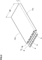
- the band layer 8 is made up of a jointless ply 12 formed by spirally winding a long band-like ply 11 (shown in Figure 2 ) on the outside of the belt layer 7.
- the band-like ply 11 has a narrow width ribbon-like shape having a substantially rectangular cross section in which one or more of the band cords 9 arranged parallel at substantially equal intervals are coated with topping rubber 10.
- the width W1 of the band-like ply 11 is, for example, 3.0 to 15.0 mm.
- the width W1 is less than 3.0 mm, the number of the windings of the band-like ply 11 required to form the jointless ply 12 becomes increased, and the productivity is likely to decrease. On the contrary, if more than 15.0 mm, there is a tendency that wrinkles are likely to occur during the winding operation. To ensure the durability of the tire and the workability of the winding in good balance, it is preferred that the thickness t of the band-like ply 11 is 0.6 to 1.5 mm.
- the number of the band cords 9 included in one band-like ply 11 is 3 to 14.
- the jointless ply 12 is made up of a first ply portion 16, a second ply portion 17 wider than the first ply portion 16, and a third ply portion 18 narrower than the second ply portion 17.
- the first ply portion 16 is formed by continuously winding the band-like ply 11 from a starting end 11a positioned between the tire equator C and one axial end 7i of the belt layer 7 to a position on the one axial end 7i of the belt layer 7.
- the second ply portion 17 is formed by continuously winding the band-like ply 11 from a position on one axial end 16i of the first ply portion 16 to the other axial end 7t of the belt layer 7.
- the third ply portion 18 is formed by continuously winding the band-like ply 11 from a position on the other axial end 17t of the second ply portion 17, toward the tire equator C, to a terminal end 11b between the other axial end 17t of the second ply portion 17 and the tire equator C.
- one edge band ply 15A is formed by a part 17A of the second ply portion 17 lapping over the first ply portion 16 in the tire radial direction.
- the other edge band ply 15B is formed by the third ply portion 18.
- the full band ply 14 is formed by the first ply portion 16 and a part 17B of the second ply portion 17 other than the part 17A (the part 17B disposed on the other axial end side of the first ply portion 16).
- the band-like ply 11 is continuous from the starting end 11a of the first ply portion 16 to the terminal end 11b of the third ply portion 18 without interruption.
- the band cords 9 are continued without interruption. For this reason, the binding force of the belt layer 7 is further increased, and the durability of the tire is further improved.
- the side edge 11e of the band-like ply 11 contacts with the axially adjacent side edge 11e of the band-like ply 11. Thereby, the band layer 8 gives a uniform restraining force to the belt layer 7, and further improves the durability.
- the widths WC in the tire axial direction of the first ply portion 16 and the third ply portion 18 are preferably 10 to 60 mm.
- the lifting of the belt layer 7 can be effectively prevented, while suppressing an increase in the tire weight.
- the jointless ply 12 comprises circumferential-direction parts 20 in which the band-like ply 11 is wound parallel to the tire circumferential direction, and inclined parts 21 continued from the circumferential-direction parts 20 and inclined with respect to the tire circumferential direction.
- Such inclined parts 21 cause the circumferential-direction parts 20 shift in the tire axial direction corresponding to a spiral pitch at each time the band-like ply 11 goes round.
- the inclined part 21 in this embodiment cause the circumferential-direction parts 20 shift in the tire axial direction corresponding to a spiral pitch which is equal to the width W1 of the band-like ply 11.
- first ply portion 16, the second ply portion 17 and third ply portion 18 are each provided with the circumferential-direction parts 20 and the inclined parts 21.
- the inclined parts 21 of the first ply portion 16 lap over the parallel parts 20 of the second ply portion 17 in the tire radial direction.
- the inclined parts 21 of the second ply portion 17 lap over the parallel parts 20 of the first ply portion 16 and the parallel parts 20 of the third ply portion 18 in the tire radial direction.
- the inclined part 21 of the first ply portion 16 and the inclined part 21 of the second ply portion 17 which is disposed radially outside the first ply portion 16 are arranged in a V-shape continuous in the tire circumferential direction.
- the end position Pa of the inclined part 21 of the first ply portion 16 which end position is on one side in the tire circumferential direction coincides with the end position Pb of the inclined part 21 of the second ply portion 17 which end position is on the other side in the circumferential direction.
- the inclined part 21 of the second ply portion 17 and the inclined part 21 of the third ply portion 18 which is disposed radially outside the second ply portion 17 are arranged in a V-shape continuous in the tire circumferential direction although not shown.
- the end position Pa of the inclined part 21 of the second ply part 17 which end position is on one side in the tire circumferential direction coincides with the end position Pb of the inclined part 21 of the third ply section 18 which end position is on the other side in the tire circumferential direction
- the band layer 8 having a more evened thickness can be formed, and it is possible to generate a uniform restraining force.
- the starting end 11a of the band-like ply 11 is formed as an oblique side E parallel with the inclined part 21, and the oblique side E is brought into contact with the side edge 11e of the inclined part 21 of the first ply portion 16 on the most tire equator C side as shown in Figure 3
- the starting end 11b of the band-like ply 11 is formed as an oblique side E parallel with the inclined part 21, and the oblique side E is brought into contact with the side edge 11e of the inclined part 21 of the third ply part 18 on the most tire equator C side.
- the angle ⁇ of the inclined part 21 with respect to the tire circumferential direction is preferably 0.1 to 2.0 degrees. If the angle ⁇ of the inclined part 21 is less than 0.1 degrees, the circumferential length of the circumferential-direction part 20 becomes increased, and there is a possibility that the restraining force to the belt layer 7 is decreased. If the angle ⁇ of the inclined part 21 is more than 2.0 degrees, the bent angle of the band cords 9 becomes increased, and there is a possibility that corrugation and the like occurs in the band-like ply 11, and the band layer 8 can not be accurately formed.
- a manufacturing apparatus T is used in this manufacturing method.
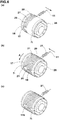
- the manufacturing apparatus T in this embodiment comprises a base 25, a drum 26 rotatably supported by the base 25, and an applicator 27 capable of supplying the band-like ply 11 to the drum 26.
- drum As the drum, a substantially cylindrical one is shown for convenience sake. But, it may be a core having a substantially same shape as the inner surface of the tire.
- the base 25 comprises a power transmission device and the like (not shown) for rotating the drum 26 through a rotary shaft 26c.
- the applicator 27 is composed of a conveyor, for example, and supplies the band-like ply 11 in the circumferential direction onto the outer peripheral surface 26a of the drum 26.
- a rubber extruder for continuously extruding the band-like ply 11 is provided (not shown).
- the band-like ply 11 is continuously supplied from the applicator 27.
- the applicator 27 is supported by, for example, a three-dimensional moving apparatus (not shown) capable of reciprocating in the axial direction and in the radial direction of the drum 26 relatively to the drum 26.
- the band layer forming step for forming the band layer 8 in this embodiment is as follows.
- the carcass 6 and belt layer 7 may be manufactured by using the manufacturing apparatus T in this embodiment.
- the starting end 11a of the band-like ply 11 guided by the applicator 27 is stuck at a position on the outer peripheral surface 26a and between the tire equator C and the one axial end 7i of the belt layer 7.
- the inclined part 21 of the first ply portion 16 is formed by moving the applicator 27 toward the one axial end 7i of the belt layer 7 (arrow direction).
- the circumferential length of the inclined part 21 of the band-like ply 11 can be adjusted by adjusting the moving speed of the applicator 27 in the tire axial direction or the rotational speed of the drum 26.
- the second step for forming the second ply portion 17 is performed.
- the applicator 27 is moved toward the other end 7t in the tire axial direction of the belt layer 7 (arrow direction).
- the fixing and the moving of the applicator 27 are repeated while rotating the drum 26 so as to form the circumferential-direction parts 20 and the inclined parts 21 of the second ply portion 17 alternately.
- the applicator 27 is moved toward one end 7i in the tire axial direction of the belt layer 7 (arrow direction).
- the fixing and the moving of the applicator 27 are repeated while rotating the drum 26 so as to form the circumferential-direction parts 20 and the inclined parts 21.
- the terminal end 11b of the band-like ply 11 which guided by the applicator 27 is stuck at a position between the tire equator C and the other end 7t side in the tire axial direction of the belt layer 7.
- the band-like ply 11 which is continuous from the starting end 11a of the first ply portion 16 to the terminal end 11b of the third ply portion 18 is used, and the band layer 8 is formed.
- the drum 26 is continuously rotated from the first step to the third step so as to give tension to the band-like ply 11 supplied from the applicator 27.
- each test tire was run under the following conditions, and the running time until damage occurred in the vicinity of the shoulder of the tread portion, and the surface temperature when the damage occurred, were measured.
- the first ply portion, the second ply portion, and the third ply portion are formed by using separate band-like plies.
Landscapes
- Engineering & Computer Science (AREA)
- Mechanical Engineering (AREA)
- Tires In General (AREA)
- Tyre Moulding (AREA)
Claims (5)
- Luftreifen mit einer Karkasse (6), die sich von einem Laufflächenabschnitt (2) zu einem Wulstkern (5) eines Wulstabschnitts (4) durch einen Seitenwandabschnitt (3) erstreckt, einer Gürtelschicht (7), die in dem Laufflächenabschnitt (2) und radial außerhalb der Karkasse (6) angeordnet ist, und einer Bandschicht (8), die radial außerhalb der Gürtelschicht (7) angeordnet ist, und wobei
die Bandschicht (8) eine nahtlose Lage (12) aufweist, die durch spiralförmiges Wickeln einer langen bandartigen Lage (11) aus einem oder mehreren Bandkorden (9), die mit Gummierungskautschuk (10) beschichtet sind, auf die radiale Außenseite der Gürtelschicht (7) gebildet ist,
wobei die nahtlose Lage (12) umfasst
einen ersten Lagenabschnitt (16), in dem die bandartige Lage (11) von einem Anfangsende (11a), das zwischen dem Reifenäquator (C) und einem Ende (7i) in der Reifenaxialrichtung der Gürtelschicht (7) positioniert ist, zu einer Position an dem einen Ende (7i) in der Reifenaxialrichtung der Gürtelschicht (7) gewickelt ist,
einen zweiten Lagenabschnitt (17), in dem die bandartige Lage (11) von der Position des ersten Lagenabschnitts (16) an dem einen Ende (7i) in der Reifenaxialrichtung zu einer Position der Gürtelschicht (7) an dem anderen Ende in der Reifenaxialrichtung gewickelt ist, und
einen dritten Lagenabschnitt (18), in dem die bandartige Lage (11) von der Position des zweiten Lagenabschnitts (17) am anderen Ende (7t) in der Reifenaxialrichtung von dem Reifenäquator bis zu einem Abschlussende (11b) gewickelt ist, das sich zwischen dem anderen Ende (7t) in der Reifenaxialrichtung der zweiten Lage (17) und dem Reifenäquator befindet, und
wobei die bandartige Lage (11) ohne Unterbrechung vom Anfangsende (11a) des ersten Lagenabschnitts (16) bis zum Abschlussende (11b) des dritten Lagenabschnitts (18) fortgesetzt ist,
dadurch gekennzeichnet, dass
die nahtlose Lage (12) Umfangsrichtungsteile (20), in denen die bandartige Lage (11) parallel zur Reifenumfangsrichtung ist, und geneigte Teile (21) umfasst, die sich von den Umfangsrichtungsteilen (20) fortsetzen und in denen die bandartige Lage (11) in Bezug auf die Reifenumfangsrichtung geneigt ist, und
wobei in dem ersten Lagenabschnitt (16) und dem zweiten Lagenabschnitt (17), die radial außerhalb des ersten Lagenabschnitts (16) angeordnet sind, Endpositionen (Pa) von geneigten Teilen (21) des ersten Lagenabschnitts (16), welche Endpositionen auf einer Seite in der Reifenumfangsrichtung liegen, jeweils mit Endpositionen (Pb) von geneigten Teilen (21) des zweiten Lagenabschnitts (17) zusammenfallen, welche Endpositionen auf der anderen Seite in der Umfangsrichtung liegen, so dass die geneigten Teile (21) des ersten Lagenabschnitts (16) und die geneigten Teile (21) des zweiten Lagenabschnitts (17) jeweils in einer V-Form in der Reifenumfangsrichtung fortgesetzt sind, und
wobei in dem zweiten Lagenabschnitt (17) und dem dritten Lagenabschnitt (18), die radial außerhalb des zweiten Lagenabschnitts (17) angeordnet sind, Endpositionen (Pa) der geneigten Teile (21) des zweiten Lagenabschnitts (17), welche Endpositionen auf der einen Seite in der Reifenumfangsrichtung liegen, jeweils mit Endpositionen (Pb) von geneigten Teilen (21) des dritten Lagenabschnitts (18) zusammenfallen, welche Endpositionen auf der anderen Seite in der Reifenumfangsrichtung liegen, so dass die geneigten Teile (21) des zweiten Lagenabschnitts (17) und die geneigten Teile (21) des dritten Lagenabschnitts (18) jeweils in einer V-Form in der Reifenumfangsrichtung fortgesetzt sind, und
wobei die bandartige Lage (11) eine Breite von 3,0 bis 15,0 mm und eine Dicke von 0,6 bis 1,5 mm aufweist und die Dehnung des Bandkords (9) bei einer Belastung von 66N 0,7 % bis 22,0 % beträgt. - Luftreifen nach Anspruch 1, wobei die Seitenkanten (11e) der bandartigen Lage (11), die in der Reifenaxialrichtung benachbart sind, miteinander in Kontakt stehen.
- Luftreifen nach einem der Ansprüche 1-2, wobei eine axial äußere Kante (8e) der Bandschicht (8) mit einer axial äußeren Kante (7e) der Gürtelschicht (7) zusammenfällt.
- Luftreifen nach einem der Ansprüche 1-3, wobei die axialen Breiten des ersten Lagenabschnitts (16) und des dritten Lagenabschnitts (18) 10 bis 60 mm betragen.
- Verfahren zur Herstellung des Luftreifens nach einem der Ansprüche 1 bis 4, welches umfasst
einen Formungsschritt einer Bandschicht (8), bei dem die bandartige Lage (11) spiralförmig auf die radiale Außenseite der Gürtelschicht (7) gewickelt wird,
wobei der Formungsschritt der Bandschicht (8) einen ersten Schritt des Formens des ersten Lagenabschnitts (16), einen zweiten Schritt des Formens des zweiten Lagenabschnitts (17) nach dem ersten Schritt und einen dritten Schritt des Formens des dritten Lagenabschnitts (18) nach dem zweiten Schritt umfasst, und
das Formen durch die Verwendung der bandförmigen Lage (11) erfolgt, die vom Anfangsende (11a) des ersten Lagenabschnitts (16) bis zum Abschlussende (11b) des dritten Lagenabschnitts (18) durchgehend ist.
Applications Claiming Priority (2)
| Application Number | Priority Date | Filing Date | Title |
|---|---|---|---|
| JP2013221417A JP5957430B2 (ja) | 2013-10-24 | 2013-10-24 | 空気入りタイヤ及びその製造方法 |
| PCT/JP2014/074554 WO2015060044A1 (ja) | 2013-10-24 | 2014-09-17 | 空気入りタイヤ及びその製造方法 |
Publications (3)
| Publication Number | Publication Date |
|---|---|
| EP3050718A1 EP3050718A1 (de) | 2016-08-03 |
| EP3050718A4 EP3050718A4 (de) | 2017-06-21 |
| EP3050718B1 true EP3050718B1 (de) | 2020-12-02 |
Family
ID=52992648
Family Applications (1)
| Application Number | Title | Priority Date | Filing Date |
|---|---|---|---|
| EP14855491.8A Active EP3050718B1 (de) | 2013-10-24 | 2014-09-17 | Luftreifen und verfahren zu dessen herstellung |
Country Status (4)
| Country | Link |
|---|---|
| US (1) | US10252574B2 (de) |
| EP (1) | EP3050718B1 (de) |
| JP (1) | JP5957430B2 (de) |
| WO (1) | WO2015060044A1 (de) |
Families Citing this family (4)
| Publication number | Priority date | Publication date | Assignee | Title |
|---|---|---|---|---|
| JP6648820B2 (ja) * | 2016-04-08 | 2020-02-14 | 横浜ゴム株式会社 | 空気入りタイヤ |
| FR3057810A1 (fr) * | 2016-10-21 | 2018-04-27 | Compagnie Generale Des Etablissements Michelin | Pneumatique a couches de travail comprenant une architecture optimisee |
| US20230041776A1 (en) * | 2020-02-27 | 2023-02-09 | The Yokohama Rubber Co., Ltd. | Pneumatic tire |
| DE102024209703A1 (de) * | 2024-10-02 | 2026-04-02 | Continental Reifen Deutschland Gmbh | Fahrzeugluftreifen |
Citations (1)
| Publication number | Priority date | Publication date | Assignee | Title |
|---|---|---|---|---|
| EP2476544A1 (de) * | 2011-01-14 | 2012-07-18 | Bridgestone Corporation | Luftreifen und Verfahren zum Bilden einer Umfangsgurtschicht dafür |
Family Cites Families (14)
| Publication number | Priority date | Publication date | Assignee | Title |
|---|---|---|---|---|
| DE3855332T2 (de) * | 1987-06-18 | 1996-10-02 | Sumitomo Rubber Ind | Gürtelreifen und Verfahren zur Herstellung |
| JPH01109108A (ja) * | 1987-10-21 | 1989-04-26 | Bridgestone Corp | 高性能空気入りラジアルタイヤ |
| AU600178B2 (en) * | 1987-10-21 | 1990-08-02 | Bridgestone Corporation | Low-section pneumatic radial tire |
| US4989658A (en) * | 1989-06-09 | 1991-02-05 | The Goodyear Tire & Rubber Company | Belt overlay structure for pneumatic tires comprising a single ribbon wrapped about the belt structure |
| US5178703A (en) * | 1990-10-24 | 1993-01-12 | Sumitomo Rubber Industries, Ltd. | Breaker with wound band |
| JP3723303B2 (ja) * | 1996-12-12 | 2005-12-07 | 横浜ゴム株式会社 | トランスポンダ付きタイヤ |
| JP4486226B2 (ja) * | 2000-07-06 | 2010-06-23 | 住友ゴム工業株式会社 | 空気入りタイヤ |
| JP4441082B2 (ja) * | 2000-08-04 | 2010-03-31 | 株式会社ブリヂストン | 空気入りラジアルタイヤ |
| EP1396355B1 (de) * | 2001-06-13 | 2009-03-18 | Sumitomo Rubber Industries, Ltd. | Radialluftreifen |
| JP4759922B2 (ja) | 2004-03-02 | 2011-08-31 | 横浜ゴム株式会社 | 空気入りラジアルタイヤ |
| JP2006069130A (ja) * | 2004-09-03 | 2006-03-16 | Toyo Tire & Rubber Co Ltd | タイヤ及びタイヤ成型方法 |
| JP2011088490A (ja) * | 2009-10-20 | 2011-05-06 | Sumitomo Rubber Ind Ltd | 空気入りタイヤ |
| JP5406706B2 (ja) * | 2009-12-29 | 2014-02-05 | 住友ゴム工業株式会社 | 空気入りタイヤ |
| US9370970B2 (en) * | 2013-11-20 | 2016-06-21 | E I Du Pont De Nemours And Company | Tire containing noise reducing fibrous layers |
-
2013
- 2013-10-24 JP JP2013221417A patent/JP5957430B2/ja active Active
-
2014
- 2014-09-17 EP EP14855491.8A patent/EP3050718B1/de active Active
- 2014-09-17 US US15/029,040 patent/US10252574B2/en active Active
- 2014-09-17 WO PCT/JP2014/074554 patent/WO2015060044A1/ja not_active Ceased
Patent Citations (1)
| Publication number | Priority date | Publication date | Assignee | Title |
|---|---|---|---|---|
| EP2476544A1 (de) * | 2011-01-14 | 2012-07-18 | Bridgestone Corporation | Luftreifen und Verfahren zum Bilden einer Umfangsgurtschicht dafür |
Also Published As
| Publication number | Publication date |
|---|---|
| EP3050718A1 (de) | 2016-08-03 |
| US10252574B2 (en) | 2019-04-09 |
| WO2015060044A1 (ja) | 2015-04-30 |
| EP3050718A4 (de) | 2017-06-21 |
| JP2015081073A (ja) | 2015-04-27 |
| JP5957430B2 (ja) | 2016-07-27 |
| US20160236515A1 (en) | 2016-08-18 |
Similar Documents
| Publication | Publication Date | Title |
|---|---|---|
| EP3127717B1 (de) | Luftreifen | |
| US10173384B2 (en) | Pneumatic tire manufacturing method | |
| EP3296126B1 (de) | Luftreifen | |
| EP3960497B1 (de) | Reifen | |
| JP2011136669A (ja) | 空気入りタイヤ及びその製造方法 | |
| US10252574B2 (en) | Pneumatic tire having a jointless band ply and method for manufacturing same | |
| US9440406B2 (en) | Pneumatic tire and method of forming circumferential belt layer of the same | |
| EP2974891B1 (de) | Luftreifen | |
| JP7135752B2 (ja) | 空気入りタイヤ | |
| JP4537517B2 (ja) | 空気入りラジアルタイヤの製造方法 | |
| JP2002019415A (ja) | 空気入りタイヤ | |
| US11772425B2 (en) | Pneumatic tire | |
| EP3521059B1 (de) | Motorradreifen | |
| JP2013107518A (ja) | 空気入りタイヤ | |
| JP2017001432A (ja) | 空気入りタイヤ | |
| JP5217347B2 (ja) | 空気入りタイヤ | |
| EP4427944B1 (de) | Reifen und herstellungsverfahren für reifen | |
| JP7642998B2 (ja) | タイヤ、タイヤの製造方法及びタイヤの設計方法 | |
| JP7425283B2 (ja) | 空気入りタイヤ | |
| EP3533623B1 (de) | Reifen | |
| JP3735445B2 (ja) | 空気入りラジアルタイヤ | |
| US20230041776A1 (en) | Pneumatic tire | |
| JP2008030660A (ja) | 空気入りタイヤ及びその製造方法 | |
| JP2020131800A (ja) | 空気入りタイヤ | |
| JP2009051136A (ja) | 空気入りタイヤの製造方法 |
Legal Events
| Date | Code | Title | Description |
|---|---|---|---|
| PUAI | Public reference made under article 153(3) epc to a published international application that has entered the european phase |
Free format text: ORIGINAL CODE: 0009012 |
|
| 17P | Request for examination filed |
Effective date: 20160429 |
|
| AK | Designated contracting states |
Kind code of ref document: A1 Designated state(s): AL AT BE BG CH CY CZ DE DK EE ES FI FR GB GR HR HU IE IS IT LI LT LU LV MC MK MT NL NO PL PT RO RS SE SI SK SM TR |
|
| AX | Request for extension of the european patent |
Extension state: BA ME |
|
| DAX | Request for extension of the european patent (deleted) | ||
| A4 | Supplementary search report drawn up and despatched |
Effective date: 20170519 |
|
| RIC1 | Information provided on ipc code assigned before grant |
Ipc: B29D 30/20 20060101ALI20170515BHEP Ipc: B60C 9/22 20060101AFI20170515BHEP Ipc: B60C 9/18 20060101ALN20170515BHEP |
|
| STAA | Information on the status of an ep patent application or granted ep patent |
Free format text: STATUS: EXAMINATION IS IN PROGRESS |
|
| 17Q | First examination report despatched |
Effective date: 20181108 |
|
| GRAP | Despatch of communication of intention to grant a patent |
Free format text: ORIGINAL CODE: EPIDOSNIGR1 |
|
| STAA | Information on the status of an ep patent application or granted ep patent |
Free format text: STATUS: GRANT OF PATENT IS INTENDED |
|
| RIC1 | Information provided on ipc code assigned before grant |
Ipc: B29D 30/30 20060101ALI20200716BHEP Ipc: B29D 30/70 20060101ALI20200716BHEP Ipc: B60C 9/18 20060101ALN20200716BHEP Ipc: B60C 9/22 20060101AFI20200716BHEP Ipc: B60C 9/20 20060101ALN20200716BHEP |
|
| INTG | Intention to grant announced |
Effective date: 20200805 |
|
| GRAS | Grant fee paid |
Free format text: ORIGINAL CODE: EPIDOSNIGR3 |
|
| GRAA | (expected) grant |
Free format text: ORIGINAL CODE: 0009210 |
|
| STAA | Information on the status of an ep patent application or granted ep patent |
Free format text: STATUS: THE PATENT HAS BEEN GRANTED |
|
| AK | Designated contracting states |
Kind code of ref document: B1 Designated state(s): AL AT BE BG CH CY CZ DE DK EE ES FI FR GB GR HR HU IE IS IT LI LT LU LV MC MK MT NL NO PL PT RO RS SE SI SK SM TR |
|
| REG | Reference to a national code |
Ref country code: GB Ref legal event code: FG4D |
|
| REG | Reference to a national code |
Ref country code: AT Ref legal event code: REF Ref document number: 1340501 Country of ref document: AT Kind code of ref document: T Effective date: 20201215 Ref country code: CH Ref legal event code: EP |
|
| REG | Reference to a national code |
Ref country code: IE Ref legal event code: FG4D |
|
| REG | Reference to a national code |
Ref country code: DE Ref legal event code: R096 Ref document number: 602014073038 Country of ref document: DE |
|
| PG25 | Lapsed in a contracting state [announced via postgrant information from national office to epo] |
Ref country code: GR Free format text: LAPSE BECAUSE OF FAILURE TO SUBMIT A TRANSLATION OF THE DESCRIPTION OR TO PAY THE FEE WITHIN THE PRESCRIBED TIME-LIMIT Effective date: 20210303 Ref country code: FI Free format text: LAPSE BECAUSE OF FAILURE TO SUBMIT A TRANSLATION OF THE DESCRIPTION OR TO PAY THE FEE WITHIN THE PRESCRIBED TIME-LIMIT Effective date: 20201202 Ref country code: RS Free format text: LAPSE BECAUSE OF FAILURE TO SUBMIT A TRANSLATION OF THE DESCRIPTION OR TO PAY THE FEE WITHIN THE PRESCRIBED TIME-LIMIT Effective date: 20201202 Ref country code: NO Free format text: LAPSE BECAUSE OF FAILURE TO SUBMIT A TRANSLATION OF THE DESCRIPTION OR TO PAY THE FEE WITHIN THE PRESCRIBED TIME-LIMIT Effective date: 20210302 |
|
| REG | Reference to a national code |
Ref country code: NL Ref legal event code: MP Effective date: 20201202 |
|
| REG | Reference to a national code |
Ref country code: AT Ref legal event code: MK05 Ref document number: 1340501 Country of ref document: AT Kind code of ref document: T Effective date: 20201202 |
|
| PG25 | Lapsed in a contracting state [announced via postgrant information from national office to epo] |
Ref country code: BG Free format text: LAPSE BECAUSE OF FAILURE TO SUBMIT A TRANSLATION OF THE DESCRIPTION OR TO PAY THE FEE WITHIN THE PRESCRIBED TIME-LIMIT Effective date: 20210302 Ref country code: SE Free format text: LAPSE BECAUSE OF FAILURE TO SUBMIT A TRANSLATION OF THE DESCRIPTION OR TO PAY THE FEE WITHIN THE PRESCRIBED TIME-LIMIT Effective date: 20201202 Ref country code: LV Free format text: LAPSE BECAUSE OF FAILURE TO SUBMIT A TRANSLATION OF THE DESCRIPTION OR TO PAY THE FEE WITHIN THE PRESCRIBED TIME-LIMIT Effective date: 20201202 Ref country code: PL Free format text: LAPSE BECAUSE OF FAILURE TO SUBMIT A TRANSLATION OF THE DESCRIPTION OR TO PAY THE FEE WITHIN THE PRESCRIBED TIME-LIMIT Effective date: 20201202 |
|
| PG25 | Lapsed in a contracting state [announced via postgrant information from national office to epo] |
Ref country code: HR Free format text: LAPSE BECAUSE OF FAILURE TO SUBMIT A TRANSLATION OF THE DESCRIPTION OR TO PAY THE FEE WITHIN THE PRESCRIBED TIME-LIMIT Effective date: 20201202 Ref country code: NL Free format text: LAPSE BECAUSE OF FAILURE TO SUBMIT A TRANSLATION OF THE DESCRIPTION OR TO PAY THE FEE WITHIN THE PRESCRIBED TIME-LIMIT Effective date: 20201202 |
|
| REG | Reference to a national code |
Ref country code: LT Ref legal event code: MG9D |
|
| PG25 | Lapsed in a contracting state [announced via postgrant information from national office to epo] |
Ref country code: LT Free format text: LAPSE BECAUSE OF FAILURE TO SUBMIT A TRANSLATION OF THE DESCRIPTION OR TO PAY THE FEE WITHIN THE PRESCRIBED TIME-LIMIT Effective date: 20201202 Ref country code: PT Free format text: LAPSE BECAUSE OF FAILURE TO SUBMIT A TRANSLATION OF THE DESCRIPTION OR TO PAY THE FEE WITHIN THE PRESCRIBED TIME-LIMIT Effective date: 20210405 Ref country code: RO Free format text: LAPSE BECAUSE OF FAILURE TO SUBMIT A TRANSLATION OF THE DESCRIPTION OR TO PAY THE FEE WITHIN THE PRESCRIBED TIME-LIMIT Effective date: 20201202 Ref country code: SK Free format text: LAPSE BECAUSE OF FAILURE TO SUBMIT A TRANSLATION OF THE DESCRIPTION OR TO PAY THE FEE WITHIN THE PRESCRIBED TIME-LIMIT Effective date: 20201202 Ref country code: SM Free format text: LAPSE BECAUSE OF FAILURE TO SUBMIT A TRANSLATION OF THE DESCRIPTION OR TO PAY THE FEE WITHIN THE PRESCRIBED TIME-LIMIT Effective date: 20201202 Ref country code: EE Free format text: LAPSE BECAUSE OF FAILURE TO SUBMIT A TRANSLATION OF THE DESCRIPTION OR TO PAY THE FEE WITHIN THE PRESCRIBED TIME-LIMIT Effective date: 20201202 Ref country code: CZ Free format text: LAPSE BECAUSE OF FAILURE TO SUBMIT A TRANSLATION OF THE DESCRIPTION OR TO PAY THE FEE WITHIN THE PRESCRIBED TIME-LIMIT Effective date: 20201202 |
|
| PG25 | Lapsed in a contracting state [announced via postgrant information from national office to epo] |
Ref country code: AT Free format text: LAPSE BECAUSE OF FAILURE TO SUBMIT A TRANSLATION OF THE DESCRIPTION OR TO PAY THE FEE WITHIN THE PRESCRIBED TIME-LIMIT Effective date: 20201202 |
|
| REG | Reference to a national code |
Ref country code: DE Ref legal event code: R097 Ref document number: 602014073038 Country of ref document: DE |
|
| PG25 | Lapsed in a contracting state [announced via postgrant information from national office to epo] |
Ref country code: IS Free format text: LAPSE BECAUSE OF FAILURE TO SUBMIT A TRANSLATION OF THE DESCRIPTION OR TO PAY THE FEE WITHIN THE PRESCRIBED TIME-LIMIT Effective date: 20210402 |
|
| PLBE | No opposition filed within time limit |
Free format text: ORIGINAL CODE: 0009261 |
|
| STAA | Information on the status of an ep patent application or granted ep patent |
Free format text: STATUS: NO OPPOSITION FILED WITHIN TIME LIMIT |
|
| PG25 | Lapsed in a contracting state [announced via postgrant information from national office to epo] |
Ref country code: AL Free format text: LAPSE BECAUSE OF FAILURE TO SUBMIT A TRANSLATION OF THE DESCRIPTION OR TO PAY THE FEE WITHIN THE PRESCRIBED TIME-LIMIT Effective date: 20201202 Ref country code: IT Free format text: LAPSE BECAUSE OF FAILURE TO SUBMIT A TRANSLATION OF THE DESCRIPTION OR TO PAY THE FEE WITHIN THE PRESCRIBED TIME-LIMIT Effective date: 20201202 |
|
| 26N | No opposition filed |
Effective date: 20210903 |
|
| PG25 | Lapsed in a contracting state [announced via postgrant information from national office to epo] |
Ref country code: ES Free format text: LAPSE BECAUSE OF FAILURE TO SUBMIT A TRANSLATION OF THE DESCRIPTION OR TO PAY THE FEE WITHIN THE PRESCRIBED TIME-LIMIT Effective date: 20201202 Ref country code: DK Free format text: LAPSE BECAUSE OF FAILURE TO SUBMIT A TRANSLATION OF THE DESCRIPTION OR TO PAY THE FEE WITHIN THE PRESCRIBED TIME-LIMIT Effective date: 20201202 Ref country code: SI Free format text: LAPSE BECAUSE OF FAILURE TO SUBMIT A TRANSLATION OF THE DESCRIPTION OR TO PAY THE FEE WITHIN THE PRESCRIBED TIME-LIMIT Effective date: 20201202 |
|
| REG | Reference to a national code |
Ref country code: CH Ref legal event code: PL |
|
| REG | Reference to a national code |
Ref country code: BE Ref legal event code: MM Effective date: 20210930 |
|
| GBPC | Gb: european patent ceased through non-payment of renewal fee |
Effective date: 20210917 |
|
| PG25 | Lapsed in a contracting state [announced via postgrant information from national office to epo] |
Ref country code: IS Free format text: LAPSE BECAUSE OF FAILURE TO SUBMIT A TRANSLATION OF THE DESCRIPTION OR TO PAY THE FEE WITHIN THE PRESCRIBED TIME-LIMIT Effective date: 20210402 Ref country code: MC Free format text: LAPSE BECAUSE OF FAILURE TO SUBMIT A TRANSLATION OF THE DESCRIPTION OR TO PAY THE FEE WITHIN THE PRESCRIBED TIME-LIMIT Effective date: 20201202 |
|
| PG25 | Lapsed in a contracting state [announced via postgrant information from national office to epo] |
Ref country code: LU Free format text: LAPSE BECAUSE OF NON-PAYMENT OF DUE FEES Effective date: 20210917 Ref country code: IE Free format text: LAPSE BECAUSE OF NON-PAYMENT OF DUE FEES Effective date: 20210917 Ref country code: GB Free format text: LAPSE BECAUSE OF NON-PAYMENT OF DUE FEES Effective date: 20210917 Ref country code: BE Free format text: LAPSE BECAUSE OF NON-PAYMENT OF DUE FEES Effective date: 20210930 |
|
| PG25 | Lapsed in a contracting state [announced via postgrant information from national office to epo] |
Ref country code: LI Free format text: LAPSE BECAUSE OF NON-PAYMENT OF DUE FEES Effective date: 20210930 Ref country code: CH Free format text: LAPSE BECAUSE OF NON-PAYMENT OF DUE FEES Effective date: 20210930 |
|
| PG25 | Lapsed in a contracting state [announced via postgrant information from national office to epo] |
Ref country code: HU Free format text: LAPSE BECAUSE OF FAILURE TO SUBMIT A TRANSLATION OF THE DESCRIPTION OR TO PAY THE FEE WITHIN THE PRESCRIBED TIME-LIMIT; INVALID AB INITIO Effective date: 20140917 |
|
| PG25 | Lapsed in a contracting state [announced via postgrant information from national office to epo] |
Ref country code: CY Free format text: LAPSE BECAUSE OF FAILURE TO SUBMIT A TRANSLATION OF THE DESCRIPTION OR TO PAY THE FEE WITHIN THE PRESCRIBED TIME-LIMIT Effective date: 20201202 |
|
| PG25 | Lapsed in a contracting state [announced via postgrant information from national office to epo] |
Ref country code: MK Free format text: LAPSE BECAUSE OF FAILURE TO SUBMIT A TRANSLATION OF THE DESCRIPTION OR TO PAY THE FEE WITHIN THE PRESCRIBED TIME-LIMIT Effective date: 20201202 |
|
| PG25 | Lapsed in a contracting state [announced via postgrant information from national office to epo] |
Ref country code: MT Free format text: LAPSE BECAUSE OF FAILURE TO SUBMIT A TRANSLATION OF THE DESCRIPTION OR TO PAY THE FEE WITHIN THE PRESCRIBED TIME-LIMIT Effective date: 20201202 |
|
| PGFP | Annual fee paid to national office [announced via postgrant information from national office to epo] |
Ref country code: DE Payment date: 20250730 Year of fee payment: 12 |
|
| PGFP | Annual fee paid to national office [announced via postgrant information from national office to epo] |
Ref country code: FR Payment date: 20250808 Year of fee payment: 12 |
|
| PG25 | Lapsed in a contracting state [announced via postgrant information from national office to epo] |
Ref country code: TR Free format text: LAPSE BECAUSE OF FAILURE TO SUBMIT A TRANSLATION OF THE DESCRIPTION OR TO PAY THE FEE WITHIN THE PRESCRIBED TIME-LIMIT Effective date: 20201202 |