EP3042789B1 - Bandage pneumatique - Google Patents
Bandage pneumatique Download PDFInfo
- Publication number
- EP3042789B1 EP3042789B1 EP14850473.1A EP14850473A EP3042789B1 EP 3042789 B1 EP3042789 B1 EP 3042789B1 EP 14850473 A EP14850473 A EP 14850473A EP 3042789 B1 EP3042789 B1 EP 3042789B1
- Authority
- EP
- European Patent Office
- Prior art keywords
- center
- grooves
- groove
- shoulder
- lateral grooves
- Prior art date
- Legal status (The legal status is an assumption and is not a legal conclusion. Google has not performed a legal analysis and makes no representation as to the accuracy of the status listed.)
- Active
Links
- 239000011295 pitch Substances 0.000 description 24
- XLYOFNOQVPJJNP-UHFFFAOYSA-N water Substances O XLYOFNOQVPJJNP-UHFFFAOYSA-N 0.000 description 16
- 230000003247 decreasing effect Effects 0.000 description 8
- 239000011324 bead Substances 0.000 description 7
- 230000001154 acute effect Effects 0.000 description 5
- 230000004323 axial length Effects 0.000 description 5
- 230000007423 decrease Effects 0.000 description 3
- 239000010426 asphalt Substances 0.000 description 2
- 230000000052 comparative effect Effects 0.000 description 2
- 230000000694 effects Effects 0.000 description 2
- 238000010998 test method Methods 0.000 description 2
- 229910000831 Steel Inorganic materials 0.000 description 1
- 230000012447 hatching Effects 0.000 description 1
- 239000010959 steel Substances 0.000 description 1
- 230000002195 synergetic effect Effects 0.000 description 1
Images


Classifications
-
- B—PERFORMING OPERATIONS; TRANSPORTING
- B60—VEHICLES IN GENERAL
- B60C—VEHICLE TYRES; TYRE INFLATION; TYRE CHANGING; CONNECTING VALVES TO INFLATABLE ELASTIC BODIES IN GENERAL; DEVICES OR ARRANGEMENTS RELATED TO TYRES
- B60C11/00—Tyre tread bands; Tread patterns; Anti-skid inserts
- B60C11/03—Tread patterns
- B60C11/0327—Tread patterns characterised by special properties of the tread pattern
- B60C11/033—Tread patterns characterised by special properties of the tread pattern by the void or net-to-gross ratios of the patterns
-
- B—PERFORMING OPERATIONS; TRANSPORTING
- B60—VEHICLES IN GENERAL
- B60C—VEHICLE TYRES; TYRE INFLATION; TYRE CHANGING; CONNECTING VALVES TO INFLATABLE ELASTIC BODIES IN GENERAL; DEVICES OR ARRANGEMENTS RELATED TO TYRES
- B60C11/00—Tyre tread bands; Tread patterns; Anti-skid inserts
- B60C11/03—Tread patterns
- B60C11/0306—Patterns comprising block rows or discontinuous ribs
-
- B—PERFORMING OPERATIONS; TRANSPORTING
- B60—VEHICLES IN GENERAL
- B60C—VEHICLE TYRES; TYRE INFLATION; TYRE CHANGING; CONNECTING VALVES TO INFLATABLE ELASTIC BODIES IN GENERAL; DEVICES OR ARRANGEMENTS RELATED TO TYRES
- B60C11/00—Tyre tread bands; Tread patterns; Anti-skid inserts
- B60C11/03—Tread patterns
- B60C11/0302—Tread patterns directional pattern, i.e. with main rolling direction
-
- B—PERFORMING OPERATIONS; TRANSPORTING
- B60—VEHICLES IN GENERAL
- B60C—VEHICLE TYRES; TYRE INFLATION; TYRE CHANGING; CONNECTING VALVES TO INFLATABLE ELASTIC BODIES IN GENERAL; DEVICES OR ARRANGEMENTS RELATED TO TYRES
- B60C11/00—Tyre tread bands; Tread patterns; Anti-skid inserts
- B60C11/03—Tread patterns
- B60C11/0306—Patterns comprising block rows or discontinuous ribs
- B60C11/0309—Patterns comprising block rows or discontinuous ribs further characterised by the groove cross-section
-
- B—PERFORMING OPERATIONS; TRANSPORTING
- B60—VEHICLES IN GENERAL
- B60C—VEHICLE TYRES; TYRE INFLATION; TYRE CHANGING; CONNECTING VALVES TO INFLATABLE ELASTIC BODIES IN GENERAL; DEVICES OR ARRANGEMENTS RELATED TO TYRES
- B60C11/00—Tyre tread bands; Tread patterns; Anti-skid inserts
- B60C11/03—Tread patterns
- B60C11/13—Tread patterns characterised by the groove cross-section, e.g. for buttressing or preventing stone-trapping
- B60C11/1369—Tie bars for linking block elements and bridging the groove
-
- B—PERFORMING OPERATIONS; TRANSPORTING
- B60—VEHICLES IN GENERAL
- B60C—VEHICLE TYRES; TYRE INFLATION; TYRE CHANGING; CONNECTING VALVES TO INFLATABLE ELASTIC BODIES IN GENERAL; DEVICES OR ARRANGEMENTS RELATED TO TYRES
- B60C11/00—Tyre tread bands; Tread patterns; Anti-skid inserts
- B60C11/03—Tread patterns
- B60C11/0327—Tread patterns characterised by special properties of the tread pattern
- B60C2011/0334—Stiffness
-
- B—PERFORMING OPERATIONS; TRANSPORTING
- B60—VEHICLES IN GENERAL
- B60C—VEHICLE TYRES; TYRE INFLATION; TYRE CHANGING; CONNECTING VALVES TO INFLATABLE ELASTIC BODIES IN GENERAL; DEVICES OR ARRANGEMENTS RELATED TO TYRES
- B60C11/00—Tyre tread bands; Tread patterns; Anti-skid inserts
- B60C11/03—Tread patterns
- B60C2011/0337—Tread patterns characterised by particular design features of the pattern
- B60C2011/0339—Grooves
- B60C2011/0341—Circumferential grooves
- B60C2011/0346—Circumferential grooves with zigzag shape
-
- B—PERFORMING OPERATIONS; TRANSPORTING
- B60—VEHICLES IN GENERAL
- B60C—VEHICLE TYRES; TYRE INFLATION; TYRE CHANGING; CONNECTING VALVES TO INFLATABLE ELASTIC BODIES IN GENERAL; DEVICES OR ARRANGEMENTS RELATED TO TYRES
- B60C11/00—Tyre tread bands; Tread patterns; Anti-skid inserts
- B60C11/03—Tread patterns
- B60C2011/0337—Tread patterns characterised by particular design features of the pattern
- B60C2011/0339—Grooves
- B60C2011/0341—Circumferential grooves
- B60C2011/0353—Circumferential grooves characterised by width
-
- B—PERFORMING OPERATIONS; TRANSPORTING
- B60—VEHICLES IN GENERAL
- B60C—VEHICLE TYRES; TYRE INFLATION; TYRE CHANGING; CONNECTING VALVES TO INFLATABLE ELASTIC BODIES IN GENERAL; DEVICES OR ARRANGEMENTS RELATED TO TYRES
- B60C11/00—Tyre tread bands; Tread patterns; Anti-skid inserts
- B60C11/03—Tread patterns
- B60C2011/0337—Tread patterns characterised by particular design features of the pattern
- B60C2011/0339—Grooves
- B60C2011/0358—Lateral grooves, i.e. having an angle of 45 to 90 degees to the equatorial plane
- B60C2011/036—Narrow grooves, i.e. having a width of less than 3 mm
-
- B—PERFORMING OPERATIONS; TRANSPORTING
- B60—VEHICLES IN GENERAL
- B60C—VEHICLE TYRES; TYRE INFLATION; TYRE CHANGING; CONNECTING VALVES TO INFLATABLE ELASTIC BODIES IN GENERAL; DEVICES OR ARRANGEMENTS RELATED TO TYRES
- B60C11/00—Tyre tread bands; Tread patterns; Anti-skid inserts
- B60C11/03—Tread patterns
- B60C2011/0337—Tread patterns characterised by particular design features of the pattern
- B60C2011/0339—Grooves
- B60C2011/0358—Lateral grooves, i.e. having an angle of 45 to 90 degees to the equatorial plane
- B60C2011/0365—Lateral grooves, i.e. having an angle of 45 to 90 degees to the equatorial plane characterised by width
-
- B—PERFORMING OPERATIONS; TRANSPORTING
- B60—VEHICLES IN GENERAL
- B60C—VEHICLE TYRES; TYRE INFLATION; TYRE CHANGING; CONNECTING VALVES TO INFLATABLE ELASTIC BODIES IN GENERAL; DEVICES OR ARRANGEMENTS RELATED TO TYRES
- B60C11/00—Tyre tread bands; Tread patterns; Anti-skid inserts
- B60C11/03—Tread patterns
- B60C2011/0337—Tread patterns characterised by particular design features of the pattern
- B60C2011/0339—Grooves
- B60C2011/0358—Lateral grooves, i.e. having an angle of 45 to 90 degees to the equatorial plane
- B60C2011/0372—Lateral grooves, i.e. having an angle of 45 to 90 degees to the equatorial plane with particular inclination angles
-
- B—PERFORMING OPERATIONS; TRANSPORTING
- B60—VEHICLES IN GENERAL
- B60C—VEHICLE TYRES; TYRE INFLATION; TYRE CHANGING; CONNECTING VALVES TO INFLATABLE ELASTIC BODIES IN GENERAL; DEVICES OR ARRANGEMENTS RELATED TO TYRES
- B60C2200/00—Tyres specially adapted for particular applications
- B60C2200/06—Tyres specially adapted for particular applications for heavy duty vehicles
Definitions
- the present invention relates to a pneumatic tire improved in wet performance and wear resistance in good balance.
- a pneumatic tire which is provided with a tread portion with a plurality of blocks defined by a plurality of main grooves extending in the tire circumferential direction, and a plurality of lateral grooves extending in the tire axial direction.
- Patent Document 1 and Patent Document 2 there have been disclosed pneumatic tires provided with center blocks divided by center main grooves, middle main grooves and center lateral grooves; middle blocks divided by the middle main grooves, the shoulder main grooves and middle lateral grooves; and shoulder blocks divided by the shoulder main grooves, tread edges and shoulder lateral grooves.
- the heavy duty tires described in Patent Documents 1 and 2 have tread patterns for which a rotational direction is not specified, wherein the axial length of a prior-contacting-side edge of one of a pair of center blocks arranged in the tire axial direction is shorter than the axial length of a prior-contacting-side edge of the other. Consequently, in the vicinity of the prior-contacting-side edge of one of the blocks, the block rigidity becomes insufficient, and local slippage occurs when contacting with the ground, therefore, uneven wear is likely to occur.
- the angle formed between the middle main groove and the center lateral groove becomes an acute angle, therefore, water in the center lateral grooves is hard to be discharged to the middle main groove, and there is a possibility that the wet performance cannot be fully improved.
- US 2007/151643 A1 discloses a pneumatic tire in accordance with the preamble of claim 1.
- EP 1 026 012 A2 discloses a pneumatic tire whose tread portion is provided with two rows of central blocks, two rows of middle blocks and two rows of shoulder blocks formed by respective circumferentially and laterally extending grooves.
- the lateral grooves that form the rows of shoulder blocks have a cross section that varies along the length of the groove, in which one groove wall has a constant angle of inclination while the angle of the opposite groove wall varies.
- JP H09-226326 discloses a pneumatic tire whose tread portion is provided with circumferentially extending main grooves and lateral grooves that extend from the tire equator towards a respective tread edge.
- the width of the lateral groove gradually decreases towards the tread edge in such a way that the width of the groove is substantially constant in the tire axial direction when a designated load is applied to the tire.
- EP 2 730 434 A1 is part of the prior art under Article 54(3) EPC and shows related technology.
- DE 10 2011 051 387 A1 and DE 90 16 455 U1 each show a pneumatic tire whose tread portion is provided with a pair of center block rows, a pair of middle block rows and a pair of shoulder block rows defined by corresponding circumferential main grooves and a plurality of lateral grooves connecting the various main grooves.
- the present invention was made in view of the circumstances as above, and a primary object is to provide a pneumatic tire improved in the wet performance and wear resistance in good balance.
- Claim 1 provides a pneumatic tire according to the present invention.
- the ratio WC / WA of the groove width WC of the first and second portions of the shoulder lateral grooves and the groove width WA of the first and second portions of the center lateral grooves is 1.6 to 2.0.
- the groove width WA of the first and second portions of the center lateral grooves, the groove width WB of the first and second portions of the middle lateral grooves, and the groove width WC of the first and second portions of the shoulder lateral grooves are not less than 4 mm.
- a ratio Lc / Lm of a land ratio Lc of center regions which are each defined between tire-circumferential-direction lines passing through both ends in the tire axial direction of the center blocks of each center block row and a land ratio Lm of middle areas which are each defined between tire-circumferential-direction lines passing through both ends in the tire axial direction of the middle blocks of each middle block row is 1.05 to 1.25.
- the angle with respect to the tire axial direction of the center lateral grooves is 10 degrees to 30 degrees.
- the tread portion is provided with a directional pattern for which a rotational direction is specified.
- the center lateral grooves each have a tie bar raising from the groove bottom and connecting between the adjacent center blocks.
- the groove width WA of the center lateral grooves is equal to the groove width WB of the middle lateral grooves, and the ratio WC / WA of the groove width WC of the shoulder lateral grooves and the groove width WA of the center lateral grooves is 1.3 to 2.3.
- the allocation of the groove width WA of the center lateral grooves, the groove width WB of the middle lateral grooves, and the groove width WC of the shoulder lateral grooves becomes proper, and it is possible to achieve both of the wet performance and wear resistance. More specifically, because the groove width WC is larger than the groove width WA and the groove width WB, water in the tread surface is quickly discharged to the outside of the tread edge through the shoulder lateral grooves. Thereby, it is possible to improve the wet performance, while securing sufficient wear resistance by a high land ratio.
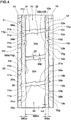
- Figure 1 is a tire meridian cross sectional view including the tire rotational axis, of a pneumatic tire 1 as first embodiment of the present invention under the normal state.
- the normal state is an unloaded state of the tire which is mounted on a normal rim RM and inflated to a normal internal pressure.
- dimensions of various portions of the tire are values measured in the normal state unless otherwise noted.
- the "normal rim” is a rim specified for the tire by a standard included in a standardization system on which the tire is based, for example, "Standard rim” in JATMA, "Design Rim” in TRA, “Measuring Rim” in ETRTO.
- the "normal internal pressure” is an air pressure specified for the tire by a standard included in a standardization system on which the tire is based, for example, "Maximum air pressure” in JATMA, the maximum value listed in the "TIRE LOAD LIMITS AT VARIOUS COLD INFLATION PRESSURES" table in TRA, and "INFLATION PRESSURE” in ETRTO.
- the pneumatic tire 1 comprises a toroidal carcass 6 extending from a tread portion 2 to a bead core 5 of a bead portion 4 through a sidewall portion 3, and a belt layer 7 disposed radially outside of the carcass 6 and in the tread portion 2, and the like.
- the pneumatic tire 1 is a tubeless tire to be mounted on a 15 degree tapered rim RM.
- the carcass 6 is composed of a carcass ply 6A of carcass cords arranged at an angle of for example 80 to 90 degrees with respect to the tire equator C.
- the carcass ply 6A is successively provided with a ply turnup portion 6b folded back around the bead core 5 from the axially inside to the outside.
- a triangular bead apex rubber 8 extending radially outwardly from the bead core 5.
- the belt layer 7 is disposed radially outside the carcass 6 and within the tread portion 2.
- the belt layer 7 is composed of a plurality of belt plies using steel belt cords.
- the belt layer 7 in this embodiment comprises four plies which are an innermost belt ply 7A of belt cords arranged at an angle of about 60 +/- 10 degrees with respect to the tire equator C for example, and belt plies 7B, 7C and 7D of belt cords arranged at small angles of about 15 degrees to about 35 degrees with respect to the tire equator C which are arranged outside the innermost belt ply in sequence.
- the belt layer 7 increases the belt rigidity and firmly reinforces almost entire width of the tread portion 2 by being provided with at least one position at which the belt cords intersect with each other between the plies.
- the bead core 5 has a laterally-long flat hexagonal cross sectional shape, and its radially inner surface is inclined at an angle of 12 degrees to 18 degrees with respect to the tire axial direction, and thereby the engage force with the rim RM is increased over a wide range.
- Figure 2 is a developed view of the tread portion 2 of the pneumatic tire 1 in this embodiment.
- the tread portion 2 has a directional pattern for which a rotational direction R of the tire is specified.
- the rotational direction R is indicated in the sidewall portion 3 by characters or the like for example.
- a center main groove 10 extending continuously in the tire circumferential direction on the tire equator C
- a pair of middle main grooves 11 disposed on both sides of the tire equator C and extending zigzag and continuously in the tire circumferential direction
- a pair of shoulder main grooves 12 extending zigzag and continuously in the tire circumferential direction on the axially inside of the tread edges Te and on the axially outside of the middle main grooves 11.
- the tread edge Te means the axially outermost ground contacting edge when the tire under the normal state is contacted with a plane by loading a normal load at a camber angle of 0 degree.
- the "normal load” is a load specified for the tire by a standard included in a standardization system on which the tire is based, "Maximum load capacity" in JATMA, the maximum value described in "TIRE LOAD LIMITS AT VARIOUS COLD INFLATION PRESSURES" table in TRA, "Load capacity" in ETRTO.
- the center main groove 10 extends straight in the tire circumferential direction. By the center main groove 10 disposed on the tire equator C, the drainage in the tread portion 2 is increased, and the wet performance is improved.
- the groove width W1 of the center main groove 10 is preferably not less than 0.8%, more preferably not less than 1.2%, but preferably not more than 2.4, more preferably not more than 2.0 of the tread width TW.
- the groove width W1 of the center main groove 10 is less than 0.8% of the tread width TW, then the groove volume becomes insufficient in the vicinity of the tire equator C where the ground pressure is high, and there is a possibility that the drainage can not be fully improved. Meanwhile, if the groove width W1 of the center main groove 10 exceeds 2.4% of the tread width TW, then since the actual ground contact area of the center land portion 13 where the ground contact pressure is high is decreased, the load applied per unit area becomes increased, and there is a possibility that the wear resistance is decreased.
- the middle main groove 11 has long segments 11a inclined with respect to the tire circumferential direction, and short segments 11b inclined to the opposite direction to the long segments 11a and being smaller in the circumferential length than the long segment 11a.
- the short segments 11b are inclined to the axially outside toward the later-contacting-side from the prior-contacting-side in the rotational direction.
- the long segments 11a and the short segments 11b are alternately arranged in the tire circumferential direction to constitute the zigzag middle main groove 11.
- the angle ⁇ 1 with respect to the tire circumferential direction of the long segment 11a of the middle main groove 11 is preferably 2 to 10 degrees for example. If the angle ⁇ 1 is less than 2 degrees, there is a possibility that the rigidity in the tire axial direction of the tread portion 2 decreases. If the angle ⁇ 1 is more than 10 degrees, there is a possibility that the drainage performance of the tire can not be fully improved.
- the shoulder main groove 12 has long segments 12a inclined with respect to the tire circumferential direction, and short segments 12b inclined to the opposite direction to the long segments 12a and being smaller in the circumferential length than the long segment 12a.
- the short segments 12b are inclined to the same direction as the short segments 11b of the middle main groove 11.
- the long segments 12a and the short segments 12b are arranged alternately in the tire circumferential direction to constitute the zigzag shoulder main groove 12.
- the angle ⁇ 2 with respect to the tire circumferential direction of the long segments 12a of the shoulder main groove 12 is, for example, the same as the angle ⁇ 1.
- the zigzag pitches of the middle main groove 11 are equal to the zigzag pitches of the shoulder main groove 12.
- the zigzag of the middle main grooves 11 and the zigzag of the shoulder main groove 12 are arranged so that the phases are shifted in the tire circumferential direction.
- the middle main grooves 11 and the shoulder main grooves 12 noise generated from the middle main grooves 11 and the shoulder main groove 12 is dispersed, and the noise performance is improved.
- the groove width W3 of the shoulder main grooves 12 is larger than the groove width W1 of the center main grooves 10, and the groove width W2 of the middle main grooves 11 is larger than the groove width W3 of the shoulder main grooves 12.
- the groove depths of the center main groove 10, the middle main grooves 11 and the shoulder main grooves 12 are 15 to 25 mm.
- the tread portion 2 is divided into a plurality of regions.
- the tread portion 2 has a pair of center land portions 13 between the center main groove 10 and the middle main grooves 11, a pair of middle land portions 14 between the middle main grooves 11 and the shoulder main groove 12, and a pair of shoulder land portions 15 located axially outside of the shoulder main grooves 12.
- the center land portion 13 and the middle land portion 14 are disposed on both sides of the middle main groove 11, the center land portion 13 and the middle land portion 14 are disposed.
- the middle land portion 14 and the shoulder land portion 15 are disposed.
- FIG. 3 there is shown an enlarged view of the center land portion 13.
- the center land portion 13 is provided with a plurality of center lateral grooves 21. In order to obtain sufficient drainage, it is preferred that at least fifty center lateral grooves 21 are disposed.
- the center lateral groove 21 extends in the axial direction of the tire, and connects between the center main groove 10 and the middle main groove 11 on both sides of the center land portion 13.
- the center land portion 13 is a block row in which a plurality of center blocks 22 are arranged. Since the center lateral grooves 21 are inclined with respect to the tire axial direction, the treads 22s of the center blocks 22 in this embodiment have a substantially parallelogram shape.
- the middle main groove 11 has a groove edge 11d on the center land portion 13 side and a groove edge 11e on the middle land portion 14 side.
- vertices 11f of the groove edge 11d on the most groove center line 11c side are positioned on the center land portion 13 side of vertices 11g of the groove edge 11e on the most groove center line 11c side.
- the axial distance WEm between the vertices 11f of the groove edge 11d on the most groove center line 11c side, and the vertices 11g of the groove edge 11e on the most groove center line 11c side is 0.07 to 0.13 times the maximum width WDC in the tire axial direction of the center block 22. If the axial distance WEm between the vertices 11f and 11g is less than 0.07 times the maximum axial width WDc of the center block 22, there is a possibility that the drainage is not fully improved. If the axial distance WEm between the vertices 11f and 11g is more than 0.13 times the maximum axial width WDc of the center block 22, there is a possibility that the wear resistance of the center land portion 13 is reduced.
- the middle main groove 11 has axially inner zigzag vertices 11p and axially outer zigzag vertices 11r which are positioned on the groove center line 11c.
- the center lateral grooves 21 intersect with the middle main grooves 11 at the zigzag vertices 11r of the middle main grooves 11. Thereby, water flow in the middle main grooves 11 and the center lateral groove 21 is smoothened.
- “the center lateral grooves 21 intersect with the middle main grooves 11 at the zigzag vertices 11r of the middle main grooves 11” means that the zigzag vertex 11r of the groove center line 11c of the middle main groove 11 exists within a region 11s shown in Figure 3 by hatching in which the middle main groove 11 and the center lateral groove 21 intersect (the same applies to the intersection of the middle main grooves 11 and the middle lateral grooves 31, the intersection of the shoulder main grooves 12 and the middle lateral grooves 31, and the intersection of the shoulder main grooves 12 and the shoulder lateral grooves 41).
- the center lateral groove 21 is a zigzag groove having a first portion 21a extending obliquely with respect to the tire axial direction, a second portion 21b shifted in the tire circumferential direction from the first portion 21a and extending parallel with the first portion 21a, and a third portion 21c connecting between the first portion 21a and the second portion 21b. It is preferable that the depth of the center lateral grooves 21 is, for example, not more than the depth of the middle main grooves 11.
- the pitches of the center lateral grooves 21 are two times the zigzag pitches of the middle main grooves 11.
- the zigzag pitches of the middle main grooves 11 is 1/2 times the pitches of the center lateral grooves 21. Therefore, the center block 22 is provided in a central portion in the tire circumferential direction of its tread 22s with a zigzag block vertex 22a facing the middle main groove 11 and projecting outwardly in the tire axial direction.
- chamfers 24a and 24b are formed at block vertices at which the center main groove 10 and the center lateral grooves 21 intersect, and chamfers 25a and 25b are formed at block vertices at which the middle main grooves 11 and the center lateral grooves 21 intersect.
- Such chamfers 24a, 24b, 25a and 25b alleviate stress concentration on the block vertices, and suppress damage such as chipping.
- rounded corners may be formed.
- Figure 4 shows an enlarged view of the middle land portion 14.
- the middle land portion 14 is provided with a plurality of middle lateral grooves 31. In order to obtain sufficient drainage, it is preferred that at least fifty middle lateral grooves 31 are provided.
- the middle lateral groove 31 extends in the tire axial direction, and one end is connected to the middle main groove 11 and the other end is connected to the shoulder main groove 12.
- the middle land portion 14 is a block row in which a plurality of middle blocks 32 are arranged.
- the center blocks 22 and the middle blocks 32 positioned on both sides of the middle main groove 11 are arranged so as to shift in the tire circumferential direction by a half pitch. Since the middle lateral grooves 31 are inclined with respect to the tire axial direction, the treads 32s of the middle blocks 32 in this embodiment have a substantially parallelogram shape.
- the shoulder main groove 12 has a groove edge 12d on the middle land portion 14 side and a groove edge 12e on the shoulder land portion 15 side.
- the vertices 12f of the groove edge 12d on the most groove center line 12c side are positioned on the middle land portion 14 side of the vertices 12g of the groove edge 12e on the most groove center line 12c side.
- the axial distance WEm between the vertices 11f of the groove edge 11d on the most groove center line 11c side, and the vertices 11g of the groove edge 11e on the most groove center line 11c side is 0.07 to 0.13 times the maximum axial width WDm of the middle blocks 32. If the axial distance WEm between the vertices 11f and the vertices 11g is less than 0.07 times the maximum axial width WDm of the middle blocks 32, there is a possibility that the drainage is not fully improved.
- the axial distance WEm between the vertices 11f and the vertices 11g is more than 0.13 times the maximum axial width WDm of the middle blocks 32, there is a possibility that the wear resistance of the middle land portion 14 is deteriorated.
- the axial distance WEs between the vertices 12f of the groove edge 12d on the most groove center line 12c side, and the vertices 12g of the groove edge 12e on the most groove center line 12c side is 0.07 to 0.13 times the maximum axial width WDm of the middle blocks 32. If the axial distance WEs between the vertices 12f and the vertices 12g is less than 0.07 times the maximum axial width WDm of the middle blocks 32, there is a possibility that the drainage performance is not fully improved.
- the axial distance WEs between the vertices 12f and the vertices 12g is more than 0.13 times the maximum axial width WDm of the middle blocks 32, there is a possibility that the wear resistance of the middle land portion 14 is deteriorated.
- the shoulder main groove 12 has axially inner zigzag vertices 12p and axially outer zigzag vertices 12r which are on the groove center line 12c as shown in Figure 4 .
- the middle main grooves 11 intersect the middle axial groove 31 at the zigzag vertices 11p of the middle main groove 11. As a result, water flow in the middle main groove 11 and the middle lateral grooves 31 is smoothened.
- the middle lateral grooves 31 intersect the shoulder main groove 12 at the zigzag vertices 12p of the shoulder main groove 12. Thereby, water flow in the shoulder main groove 12 and the middle lateral grooves 31 is smoothened.
- the middle lateral groove 31 is a zigzag-shaped groove having a first portion 31a which extends obliquely with respect to the tire axial direction, a second portion 31b which extends parallel with the first portion 31a and which is shifted in the tire circumferential direction from the first portion 31a, and a third portion 31c which connects between the first portion 31a and the second portion 31b.
- the depth of the middle lateral grooves 31 is preferably not more than the depths of the middle main groove 11 and the shoulder main groove 12.
- the pitches of the middle lateral grooves 31 are equal to the center lateral grooves 21 and two times the zigzag pitches of the middle main groove 11 and the shoulder main groove 12.
- the zigzag pitches of the middle main groove 11 and the shoulder main groove 12 are 1/2 times the pitches of the middle lateral grooves 31. Therefore, a center portion in the tire circumferential direction of the tread 32s of the middle block 32 is provided with zigzag block vertices 32a projecting axially inwardly and facing the middle main groove 11, and zigzag block vertices 32b projecting axially outwardly and facing the shoulder main groove 12.
- the block vertices, at which the middle lateral grooves 31 intersect the middle main groove 11, are provided with chamfers 34a and 34b.
- the block vertices, at which the middle lateral grooves 31 intersect the shoulder main groove 12, are provided with chamfers 35a and 35b.
- Such chamfers 34a, 34b, 35a and 35b alleviate stress concentration on the block vertices, and suppress damage such as chipping.
- rounded corners may be formed.
- FIG. 5 an enlarged view of the shoulder land portion 15 is shown.
- the shoulder land portion 15 is provided with a plurality of the shoulder lateral grooves 41.
- the shoulder lateral groove 41 extends in the tire axial direction, and one end and the other end are respectively connected to the shoulder main groove 12 and the tread edge Te.
- the shoulder land portion 15 is a block row in which a plurality of shoulder blocks 42 are arranged.
- the middle blocks 32 and the shoulder blocks 42 positioned on both sides of the shoulder main groove 12 are shifted in the tire circumferential direction by a half pitch as shown in Figure 2 .
- the axial distance WEs between the vertices 12f of the groove edge 12d on the most groove center line 12c side, and the vertices 12g of the groove edge 12e on the most groove center line 12c side is 0.07 to 0.13 times the maximum axial width WDs of the shoulder blocks 42. If the axial distance WEs between the vertices 12f and the vertices 12g is less than 0.07 times the maximum axial width WDs of the shoulder blocks 42, there is a possibility that the drainage performance is not fully improved.
- the shoulder lateral grooves 41 intersect the shoulder main groove 12 at the zigzag vertices 12r of the shoulder main groove 12. Thereby, the flow of water in the shoulder lateral groove 41 and the shoulder main grooves 12 is smoothened.
- the shoulder lateral groove 41 is a zigzag-shaped groove having a first portion 41a which extends obliquely with respect to the tire axial direction, a second portion 41b which extends parallel with the first portion 41a and which is shifted in the tire circumferential direction from the first portion 41a, and a third portion 41c which connect between the first part 41a and the second portion 41b.
- the depth of the shoulder lateral grooves 41 is preferably not more than the depths of the middle main groove 11 and the shoulder main groove 12.
- the pitches of the shoulder lateral grooves 41 are equal to the middle lateral grooves 31 and two times the zigzag pitches of the shoulder main groove 12.
- the zigzag pitches of the shoulder main groove 12 is 1/2 times the pitches of the shoulder lateral grooves 41. Therefore, a central portion in the tire circumferential direction of the tread 42s of the shoulder block 42 is provided with a zigzag block vertex 42a projecting axially inwardly and facing the shoulder main groove 12.
- the block vertices at which the shoulder lateral grooves 41 intersect the shoulder main groove 12 are provided with chamfers 44a and 44b.
- Such chamfers 44a and 44b alleviate stress concentration on the block vertices, and suppress damage such as chipping.
- rounded corners may be formed.
- the groove width WB of the middle lateral grooves 31 and the groove width WA of the center lateral grooves 21 shown in Figures 2 to 5 are the same. Further, the ratio WC / WA of the groove width WC of the shoulder lateral grooves 41 and the groove width WA of the center lateral grooves 21 is 1.3 or more, preferably 1.6 or more, and 2.3 or less, preferably 2.0 or less.
- the groove width WA, the groove width WB, and the groove width WC are properly allocated, and it becomes possible to achieve both of the wet performance and the wear resistance.
- the groove width WC is larger than the groove width WA and the groove width WB, water in the tread surface is quickly discharged toward the outside of the tread edge Te through the shoulder lateral grooves 41. Thereby, the wet performance can be improved, while securing the sufficient wear resistance by the larger land ratio.
- the ratio WC / WA of the groove width WA of the shoulder lateral grooves 41 and the groove width WC of the center lateral grooves 21 is less than 1.3, there is a possibility that the water in the tread surface becomes difficult to be rapidly discharged toward the outside of the tread edge Te through the shoulder lateral grooves 41.
- the ratio WC / WA of the groove width WA of the shoulder lateral grooves 41 and the groove width WC of the center lateral grooves 21 is more than 2.3, there is a possibility that the rubber volume of the shoulder blocks 42 becomes insufficient, and uneven wear so called shoulder drop wear is caused.
- the groove width WA of the center lateral grooves 21, the groove width WB of the middle lateral grooves 31, and the groove width WC of the shoulder lateral grooves 41 are at least 4 mm. If the groove width WA, the groove width WB and groove width WC is less than 4 mm, the drainage in the tread portion 2 is decreased, and there is a possibility that the wet performance can not be improved.
- a ratio Lc / Lm of a land ratio Lc of a center region 22A and a land ratio Lm of a middle region 32A is preferably 1.05 or more, more preferably 1.10 or more, and preferably 1.25 or less, more preferably 1.20 or less.
- the center region 22A is a region between tire-circumferential-direction lines 22c, 22c extending through both axial ends 22e, 22e of the center blocks 22.
- the middle region 32A is a region between tire-circumferential-direction lines 32c, 32c extending through both axial ends 32e, 32e of the middle land portion 14.
- the ratio Lc / Lm of the land ratio Lc of the center region 22A and the land ratio Lm of the middle region 32A is smaller than 1.05 times, then as the actual ground contact area of the center land portion 13 where the ground contact pressure is high is decreased, the load applied to a unit area is increased, and there is a possibility that the wear resistance is decreased.
- the ratio Lc / Lm of the land ratio Lc of the center region 22A and the land ratio Lm of the middle region 32A is more than 1.25 times, then the groove volume of in the center land portion 13 where the ground contact pressure is high becomes insufficient, and there is a possibility that the drainage is deteriorated.
- the land ratio Lc of the center region 22A is 75 to 85. If the land ratio Lc of the center region 22A is less than 75, as the actual ground contact area of the center land portion 13 where the ground contact pressure is high becomes small, there is a possibility that wear resistance is deteriorated as described above. On the other hand, if the land ratio Lc of the center region 22A exceeds 85, the center land portion 13 lacks the groove volume, and there is a possibility that the drainage performance is deteriorated.
- the land ratio Lm of the middle area 32A is 65 to 75. If the land ratio Lm of the middle region 32A is less than 65, as the actual ground contact area of the middle land portion 14 becomes small, there is a possibility that the middle land portion 14 wears unevenly. On the other hand, if the land ratio Lm of the middle region 32A is more than 75, the groove volume in the middle land portion 14 becomes insufficient, and there is a possibility that the drainage performance is deteriorated.
- the angle ⁇ 1 of the center lateral groove 21 is an angle with respect to the tire axial direction of the groove edge of the center lateral groove 21 at the vertex 26 of the center block 22.
- the angle ⁇ 2 of the middle lateral groove 31 is an angle with respect to the tire axial direction of the groove edge of the middle axial groove 31 at the vertex 36 of the middle block 32.
- the angle ⁇ 3 of the shoulder lateral groove is an angle with respect to the tire axial direction of the groove edge of the shoulder lateral groove 41 at the vertex 46 of the shoulder block 42. If the corner of each block is chamfered or rounded, the vertex is an intersection of an extension of the groove edge of each main groove and an extension of the groove edge of each lateral groove.
- FIG 6 a developed view of the tread portion 2 of the pneumatic tire in this embodiment is shown.
- the center lateral grooves 21, 21 on both sides of the center main groove 10 are shifted in the tire circumferential direction by a half pitch for example.
- pitch noises generated from the center lateral grooves 21, 21 are prevented from being superimposed, and thereby the noise performance is improved.
- the distribution of the ground contact pressure in the center land portion 13 adjacent in the tire axial direction is dispersed, and uneven wear of the center land portion 13 is suppressed.
- the center lateral grooves 21 and the middle lateral grooves 31 on both sides of the middle main groove 11 are shifted in the tire circumferential direction by a half pitch for example.
- the center blocks 22 and the middle blocks 32 disposed on both sides of the middle main groove 11 are shifted in the tire circumferential direction by a half pitch.
- pitch noises generated from the center lateral grooves 21 and the middle lateral grooves 31 are prevented from being superimposed, and thereby the noise performance is improved.
- the distribution of the ground contact pressure in the adjacent center land portion 13 and middle land portion 14 is dispersed, and uneven wear of the center land portion 13 and middle land portion 14 is suppressed.
- the center lateral grooves 21 are connected to the middle main groove 11 in the short segments 11b. Thereby, a difference occurs between the axial lengths of the opposite edges of the center lateral groove 21. More specifically, the axial length WS of the prior-contacting-side edge 22s of the center block 22 becomes larger than the axial length WE of the later-contacting-side edge 22E. Therefore, in the vicinity of the prior-contacting-side edge 22S, the rigidity of the center block 22 is increased, and uneven wear such as so-called heel-and-toe wear is suppressed. Such function and effect are particularly effective in the center land portion 13 where the ground pressure is high.
- the center lateral grooves 21 secure sufficient groove volume when the center blocks 22 contact with the ground. Moreover, as the center lateral grooves 21 and the middle main grooves 11 are inclined to the same direction, water in the center lateral grooves 21 are smoothly discharged to the middle main groove 11. By the synergistic effect of these, the drainage in the tread portion 2 is increased, and the wet performance of the pneumatic tire is improved.
- the center lateral grooves 21 in this embodiment are provided with a tie bar 23 connecting between the center blocks 22 adjacent to each other in the tire circumferential direction.
- FIG 8 A-A line cross-sectional view of the center land portion 13 in Fig. 7 , that is, the cross-sectional view of the center land portion 13 including the tie bar 23 is shown.
- the tie bar 23 is formed by a raised groove bottom of the center lateral groove 21.
- the tie bar 23 controls movements in the tire circumferential direction of the center blocks 22 when contacting with the ground, in particular, when stepping in or kicking out, and thereby suppresses uneven wear such as heel and toe wear.
- the height HT of the tie bar 23 is preferably 1/3 to 1/2 times the groove depth DA of the center lateral groove 21. If the height HT of the tie bar 23 is less than 1/3 times the groove depth DA, the movements in the tire circumferential direction of the center block 22 when contacting with the ground increase, and there is a possibility that the center blocks 22 wear unevenly. On the other hand, if the height HT of the tie bar 23 is more than 1/2 of the groove depth DA, there is a possibility that the drainage of the center lateral groove 21 is reduced.
- the axial width WT of the tie bar 23 is preferably 1/3 to 1/2 times the axial width WE of the later-contacting-side edge 22E of the center block 22. If the width WT of the tie bar 23 is less than 1/3 times the width WE of the later-contacting-side edge 22E, the movements in the tire circumferential direction of the center blocks 22 when contacting with the ground are increased, and there is a possibility that uneven wear occurs in the center blocks 22. On the other hand, if the width WT of the tie bar 23 is more than 1/2 times the width WE of the later-contacting-side edge 22E, there is a possibility that the drainage of the center lateral groove 21 is deteriorated.
- the center block 22 is provided with a plurality of center lateral shallow grooves 27.
- One end and the other end of the center lateral shallow groove 27 are connected to the center main groove 10 and the short segment 11b of the middle main groove 11, respectively.
- the center lateral shallow groove 27 is a zigzag-shaped groove having a first portion 27a which extends obliquely with respect to the tire axial direction, a second portion 27b which shifts in the tire circumferential direction from the first portion 27a and which extends parallel with the first portion 27a, and a third portion 27c which connects between the first portion 27a and the second portion 27b.
- the depth of the center lateral shallow grooves 27 is smaller than the depth of the center lateral grooves 21.
- the width of the center lateral shallow grooves 27 is smaller than the width of the center lateral grooves 21.
- FIG 9 there is shown an enlarged view of the middle land portion 14.
- the middle lateral groove 31 is inclined to the later-contacting-side in the rotational direction R.
- the middle lateral grooves 31 are inclined to the same direction as the short segments 11b of the middle main grooves 11.
- the middle lateral grooves 31 are connected to the middle main groove 11 in the short segments 11b. Thereby, water in the middle main groove 11 is smoothly discharged to the middle lateral grooves 31.
- the middle lateral grooves 31 are inclined to the same direction as the short segments 12b of the shoulder main groove 12.
- the middle lateral grooves 31 are connected to the shoulder main groove 12 in the short segments 12b. Therefore, water in the middle lateral grooves 31 are smoothly discharged to the shoulder main groove 12. Therefore, the drainage is increased from the center land portion 13 to the middle land portion 14 of the tread portion 2, and the wet performance of the pneumatic tire is improved.
- the middle block 32 is provided with a plurality of middle lateral shallow grooves 37.
- One end and the other end of the middle lateral shallow groove 37 are respectively connected to the short segment 11b of the middle main groove 11 and the short segment 12b of the shoulder main groove 12.
- the middle lateral shallow groove 37 is a zigzag-shaped groove having a first portion 37a which extends obliquely with respect to the tire axial direction, a second portion 37b which extends parallel with the first portion 37a and which is shifted in the tire circumferential direction from the first portion 37a, and a third portion 37c which connects between the first portion 37a and the second portion 37b.
- the depth of the middle lateral shallow groove 37 is smaller than the depth of the middle lateral groove 31.
- the width of the middle lateral shallow groove 37 is smaller than the width of the middle lateral grooves 31.
- FIG 10 there is shown an enlarged view of the shoulder land portion 15.
- the middle lateral grooves 31 and the shoulder lateral grooves 41 on both sides of the shoulder main groove 12 are shifted in the tire circumferential direction by a half pitch.
- the middle blocks 32 and the shoulder blocks 42 disposed on both sides of the shoulder main groove 12 are shifted in the tire circumferential direction by a half pitch.
- the middle lateral grooves 31 and shoulder lateral grooves 41 pitch sounds generated from the middle lateral grooves 31 and the shoulder lateral grooves 41 is prevented from being superimposed, and thereby the noise performance is improved.
- the distribution of the ground contact pressure in the adjacent middle land portion 14 and the adjacent shoulder land portion 15 is dispersed, and uneven wear of the middle land portion 14 and the shoulder land portion 15 is suppressed.
- the shoulder block 42 is provided with a plurality of shoulder lateral shallow grooves 47.
- One end the other end of the shoulder lateral shallow groove 47 are respectively connected to the short segment 12b of the shoulder main groove 12 and the tread edge Te.
- the shoulder lateral shallow groove 47 is a zigzag-shaped groove having a first portion 47a which extends obliquely with respect to the tire axial direction, a second portions 47b which extends parallel with the first portion 47a and which shifts in the tire circumferential direction from the first portion 47a, and a third portion 47c which connects between the first portion 47a and the second portion 47b.
- the depth of the shoulder lateral shallow groove 47 is smaller than the depth of the shoulder lateral grooves 41.
- the width of the shoulder lateral shallow groove 47 is smaller than the width of the shoulder lateral grooves 41.
- the angle ⁇ 1 with respect to the tire circumferential direction of the center lateral groove 21 is, for example, smaller than the angle ⁇ 2 with respect to the tire circumferential direction of the middle lateral groove 31, and the angle ⁇ 2 is, for example, smaller than the angle ⁇ 3 with respect to the tire circumferential direction of the shoulder lateral groove 41.
- the angle ⁇ 1 is preferably 60 degrees or more, and preferably 80 degrees or less, more preferably 75 degrees or less. If the angle ⁇ 1 is less than 60 degrees, the block vertex 26 of the center block 22 becomes an excessively acute angle, which may become a starting point of uneven wear. On the other hand, if the angle ⁇ 1 is more than 80 degrees, there is a possibility that the drainage performance of the center land portion 13 is deteriorated.
- the angle ⁇ 3 is preferably 80 degrees or more, more preferably 85 degrees or more, and preferably 90 degrees or less. If the angle ⁇ 3 is less than 80 degrees, the block vertex 46 of the shoulder block 42 becomes an excessively acute angle, which may become a starting point of uneven wear. On the other hand, if the angle ⁇ 3 is more than 90 degrees, the inclination of the shoulder lateral groove 41 with respect to the tire axial direction is reversed, and there is a possibility that the drainage performance in the shoulder land portion 15 is deteriorated.
- the groove width WA of the center lateral groove 21 is, for example, not more than the groove width WB of the middle lateral grooves 31, and the groove width WB of the middle lateral groove 31 is, for example, less than the groove width WC of the shoulder lateral groove 41.
- the ratio WC / WA of the groove width WC of the shoulder lateral groove 41 and the groove width WA of the center lateral groove 21 is preferably 1.50 or more, more preferably 1.60 or more, and preferably 2.50 or less, more preferably 2.00 or less. If the ratio WC / WA is less than 1.50, there is a possibility that the drainage from the shoulder main groove 12 to the tread edge Te becomes insufficient. On the other hand, if the ratio WC / WA is more than 2.50, the land ratio of the shoulder land portion 15 is decreased, and the wear resistance may be deteriorated.
- the ratio WC / WB of the groove width WC of the shoulder lateral groove 41 and the groove width WB of the middle lateral groove 31 is preferably 1.50 or more, more preferably 1.60 or more, and preferably 2.50 or less, more preferably 2.00 or less. If the ratio WC / WB is less than 1.50, there is a possibility that the drainage from the shoulder main groove 12 to the tread edge Te becomes insufficient similarly to the above. On the other hand, if the ratio WC / WB is more than 2.50, the land ratio of the shoulder land portion 15 is reduced similarly to the above, and there is a possibility that the wear resistance and uneven wear resistance are deteriorated.
- the ratio WA / LA of the circumferential length LA of the center block 22 and the groove width WA of the center lateral groove 21 shown in Figure 6 is 0.08 to 0.10. If the ratio WA / LA is less than 0.08, the groove width WA of the center lateral groove 21 becomes insufficient, and there is a possibility that the drainage from the vicinity of the tire equator C to the middle main groove 11 becomes insufficient. On the other hand, if the ratio WA / LA is more than 0.10, the land ratio of the center land portion 13 is decreased, and there is a possibility that the wear resistance and uneven wear resistance are deteriorated.
- the ratio WB / LB of the groove width WB of the middle lateral groove 31 shown in Figure 6 and the circumferential length LB of the middle block 32 is 0.10 to 0.20. If the ratio WB / LB is less than 0.10, the groove width WB of the middle lateral groove 31 becomes insufficient, and there is a possibility that the drainage from the vicinity of the middle main grooves 11 to the shoulder main groove 12 becomes insufficient. On the other hand, if the ratio WB / LB is more than 0.20, the land ratio of the middle land portion 14 is reduced, and there is a possibility that the wear resistance and uneven wear resistance are deteriorated.
- the ratio WC / LC of the circumferential length LC of the shoulder block 42 and the groove width WC of the shoulder lateral groove 41 shown in Figure 6 is 0.20 to 0.30. If the ratio WC / LC is less than 0.20, the groove width WC of the shoulder lateral groove 41 becomes insufficient, and there is a possibility that the drainage from the vicinity of the shoulder main groove 12 to the tread edge Te becomes insufficient. On the other hand, if the ratio WC / LC is more than 0.30, the land ratio of the shoulder land portion 15 is reduced, and there is a possibility that the wear resistance and uneven wear resistance are deteriorated.
- Pneumatic tires of size 11.00R20 having the basic structure shown in Figure 1 were experimentally manufactured based on the specifications shown in Table 1, and tested for wet braking performance and wear resistance.
- Each test tire under the conditions of a 20 x 8.00 rim and internal pressure of 780 kPa was attached to all wheels of a truck (2-D vehicle) whose maximum load was 8 tons.
- the vehicle was brought into a wet asphalt road surface having a water film of a thickness of 0.5 mm to 2.0 mm, and during running at a speed of 65 km/h, brake was applied and the distance required to decrease the speed from 60 km/h to 20 km/h was measured.
- the results are indicated by an index based on the value of Example 1 as being 100, wherein the larger the number, the better the wet performance.
- Example 1 After running for 50000 km with the vehicle. the groove depths of each tire was measured. The results are indicated by an index based on the value of Example 1 as being 100, wherein the larger the number, the better the wear resistance.
- Pneumatic tires of size 11.00R20 having the basic structure shown in Figure 6 were experimentally manufactured based on the specifications shown in Table 2, and tested for the wet performance and uneven wear resistance.
- Each test tire under the conditions of a 20 x 8.00 rim and internal pressure of 780 kPa was attached to all wheels of a truck (2-D vehicle) whose maximum load was 10 tons.
- the vehicle was brought into a wet asphalt road surface having a water film of a thickness of 5 mm, and the time required to travel 10 meters was measured from the moment the clutch was connected, while keeping the shift gears at second gear and the engine speed at 1500 rpm, and it was indexed.
- the result is a reciprocal of each traveling time and indicated by an index based on the value of Working Example 1 being 100. The larger the number, the better the drainage performance.
- Each test tire under the conditions of a 20 x 8.00 rim and internal pressure of 780 kPa was attached to one of the rear wheels of a truck (2-D vehicle) whose maximum load was 10 tons.
- Working Example 1 tire was attached, and then it was run until the wear of either tire reached 50%.
- each tire was checked for each block row in the center land portions, middle land portions and shoulder land portions, whether uneven wear was caused or not. The results are indicated by an index based on working Example 1 being 100, the larger the number, the better the uneven wear resistance.
Landscapes
- Engineering & Computer Science (AREA)
- Mechanical Engineering (AREA)
- Tires In General (AREA)
Claims (13)
- Bandage pneumatique (1) pourvu d'une portion formant bande de roulement (2) avec
une rainure principale centrale (10) s'étendant de façon continue dans la direction circonférentielle du pneumatique,
une paire de rainures principales médianes (11) s'étendant de façon continue dans la direction de la circonférence du pneumatique sur les deux côtés de la rainure principale centrale (10),
une paire de rainures principales d'épaulement (12) s'étendant en continu dans la direction circonférentielle du pneumatique entre les rainures principales centrales (11) et les bords de la bande de roulement (Te),
une pluralité de rainures latérales centrales (21) reliant la rainure principale centrale (10) et les rainures principales médianes (11),
une pluralité de rainures latérales médianes (31) reliant les rainures principales médianes (11) et les rainures principales d'épaulement (12), et
une pluralité de rainures latérales d'épaulement (41) reliant les rainures principales d'épaulement (12) et les bords de la bande de roulement (Te), de manière à avoir
une paire de rangées de bloc centraux, de blocs centraux (22) qui sont divisés par la rainure principale centrale (10), les rainures principales médianes (11) et les rainures latérales centrales (21), et agencés à intervalles dans la direction circonférentielle du pneumatique,
une paire de rangées de blocs médians, de blocs médians (32) qui sont divisés par les rainures principales médianes (11), les rainures principales d'épaulement (12) et les rainures latérales médianes (31), et agencés à intervalles dans la direction circonférentielle du pneumatique, et
une paire de rangées de blocs d'épaulement, de blocs d'épaulement (42) qui sont divisés par les rainures principales d'épaulement (12), les bords de la bande de roulement (Te) et les rainures latérales d'épaulement (41), et agencés à intervalles dans la direction circonférentielle du pneumatique,
caractérisé en ce que
chaque rainure latérale centrale (21) est une rainure en forme de zigzag ayant une première portion (21a) s'étendant en oblique par rapport à la direction axiale du pneumatique, une deuxième portion (21b) décalée dans la direction circonférentielle du pneumatique depuis la première portion (21a) et s'étendant parallèlement à la première portion (21a), et une troisième portion (21c) reliant la première portion (21a) et la deuxième portion (21b),
chaque rainure latérale médiane (31) est une rainure en forme de zigzag ayant une première portion (31a) qui s'étend en oblique par rapport à la direction axiale du pneumatique, une deuxième portion (31b) qui s'étend parallèlement à la première portion (31a) et qui est décalée dans la direction circonférentielle du pneumatique depuis la première portion (31a), et une troisième portion (31c) qui relie la première portion (31a) et la deuxième portion (31b), et
chaque rainure latérale d'épaulement (41) est une rainure en forme de zigzag ayant une première portion (41a) qui s'étend en oblique par rapport à la direction axiale du pneumatique, une deuxième portion (41b) qui s'étend parallèlement à la première portion (41a) et qui est décalée dans la direction circonférentielle du pneumatique depuis la première portion (41a), et une troisième portion (41c) qui relie la première portion (41a) et la deuxième portion (41b),
dans lequel la largeur de rainure WA de la première et de la deuxième portion (21a, 21b) des rainures latérales centrales (21) est égale à la largeur de rainure WB de la première et de la deuxième portion (31a, 31b) des rainures latérales médianes (31),
le rapport WC / WA de la largeur de rainure WC de la première et de la deuxième portion (41a, 41c) des rainures latérales d'épaulement (41) sur la largeur de rainure WA de la première et de la deuxième portion (21a, 21b) des rainures latérales centrales (21) est de 1,3 à 2,3, et
les rainures latérales centrales (21) ont chacune une barrette de liaison (23) qui se dresse depuis le fond de la rainure et qui relie les blocs centraux (22) adjacents. - Pneumatique (1) selon la revendication 1, dans lequel
le rapport WC / WA de la largeur de rainure WC de la première et de la deuxième portion (41a, 41c) des rainures latérales d'épaulement (41) sur la largeur de rainure WA de la première et de la deuxième portion (21a, 21b) des rainures latérales centrales (21) est de 1,6 à 2,0. - Pneumatique (1) selon la revendication 1 ou 2, dans lequel
la largeur de rainure WA de la première et de la deuxième portion (21a, 21b) des rainures latérales centrales (21),
la largeur de rainure WB de la première et de la deuxième portion (31a, 31b) des rainures latérales médianes (31), et
la largeur de rainure WC de la première et de la deuxième portion (41a, 41c) des rainures latérales d'épaulement (41)
ne sont pas inférieures à 4 mm. - Bandage pneumatique (1) selon l'une quelconque des revendications 1 à 3, dans lequel
un rapport Lc / Lm
d'un rapport de relief Lc de régions centrales (22A) qui sont chacune définies entre des lignes de direction circonférentielle du pneumatique (22c) passant à travers les deux extrémités (22e) dans la direction axiale du pneumatique des blocs centraux (22) de chaque rangée de blocs centraux,
sur un rapport de relief Lm des zones médianes (32A) qui sont chacune définies entre les lignes de direction circonférentielle du pneumatique (32c) passant à travers les deux extrémités (32e) dans la direction axiale du pneumatique des blocs médians (32) de chaque rangée de blocs médians est de 1,05 à 1,25. - Bandage pneumatique (1) selon l'une quelconque des revendications 1 à 4, dans lequel
l'angle par rapport à la direction axiale du pneumatique des rainures latérales centrales (21) est de 10 degrés à 30 degrés. - Bandage pneumatique (1) selon l'une quelconque des revendications 1 à 5, dans lequel
une largeur de rainure (W3) des rainures principales d'épaulement (12) est supérieure à une largeur de rainure (W1) de la rainure principale centrale (10), et
une largeur de rainure (W2) des rainures principales médianes (11) est supérieure à la largeur de rainure (W3) des rainures principales d'épaulement (12). - Bandage pneumatique (1) selon l'une quelconque des revendications 1 à 6, dans lequel
les rainures principales médianes (11) et les rainures principales d'épaulement (12) sont formées en zigzag,
les rainures principales médianes (11) sont recoupées par les rainures latérales centrales (21) et les rainures latérales médianes (31) au niveau de sommets en zigzag (12p, 12r) des rainures principales médianes (11), et
les rainures principales d'épaulement (12) sont recoupées par les rainures latérales médianes (31) et les rainures latérales d'épaulement (41) au niveau de sommets en zigzag (12p, 12r) des rainures principales d'épaulement (12). - Bandage pneumatique (1) selon l'une quelconque des revendications 1 à 7, dans lequel
la portion formant bande de roulement (2) est pourvue d'un motif directionnel pour lequel un sens de rotation (R) est spécifié. - Bandage pneumatique (1) selon la revendication 8, dans lequel
les rainures latérales centrales (21) sont inclinées vers un côté de contact ultérieur dans le sens de rotation (R), depuis l'extrémité intérieure dans la direction axiale du pneumatique vers l'extrémité extérieure,
les rainures principales médianes (11) sont en forme de zigzag, de telle sorte que des segments courts (11b) et des segments longs (11a) sont agencés en alternance,
les segments courts (11b) étant inclinés dans la même direction que les rainures latérales centrales (21), et les segments longs (11a) étant plus longs dans la longueur circonférentielle que les segments courts (11b) et étant inclinés dans la direction opposée aux segments courts (11b), et
les rainures latérales centrales (21) étant reliées aux segments courts (11b) des rainures principales médianes (11) . - Bandage pneumatique (1) selon la revendication 9, dans lequel
les rainures latérales médianes (31) sont inclinées dans la même direction que les rainures latérales centrales (21),
les rainures principales d'épaulement (12) comportent chacune des segments courts (12b) inclinés dans la même direction que les rainures latérales médianes (31), et des segments longs (12a) qui sont plus longs sur la longueur de la circonférence que les segments courts (12b) et inclinés dans la direction opposée à celle des segments courts (12b), et
les rainures latérales médianes (31) sont reliées aux segments courts (12b) des rainures principales d'épaulement (12). - Bandage pneumatique (1) selon l'une quelconque des revendications 9 ou 10, dans lequel
les rainures latérales centrales (21) sur les deux côtés de la rainure principale centrale (10) sont agencées de manière à se décaler dans la direction circonférentielle du pneumatique,
les rainures latérales centrales (21) et les rainures latérales médianes (31) sur les deux côtés de chacune des rainures principales médianes (11) sont agencées de manière à se décaler dans la direction circonférentielle du pneumatique, et
les rainures latérales médianes (31) et les rainures latérales d'épaulement (41) sur les deux côtés de chacune des rainures principales d'épaulement (12) sont agencées de manière à se décaler dans la direction circonférentielle du pneumatique. - Bandage pneumatique (1) selon l'une quelconque des revendications 9 à 11, dans lequel
un angle (γ1) par rapport à la direction circonférentielle du pneumatique des rainures latérales centrales (21) est inférieur à un angle (γ2) par rapport à la direction circonférentielle du pneumatique des rainures latérales médianes (31), et
l'angle (γ2) par rapport à la direction circonférentielle du pneumatique des rainures latérales médianes (31) est inférieur à un angle (γ3) par rapport à la direction circonférentielle du pneumatique des rainures latérales d'épaulement (41) . - Bandage pneumatique (1) selon la revendication 12, dans lequel
l'angle (γ1) par rapport à la direction circonférentielle du pneumatique des rainures latérales centrales (21) est de 60 degrés à 80 degrés, et
l'angle (γ3) par rapport à la direction circonférentielle du pneumatique des rainures latérales d'épaulement (41) est de 80 degrés à 90 degrés.
Applications Claiming Priority (3)
| Application Number | Priority Date | Filing Date | Title |
|---|---|---|---|
| JP2013209463A JP6043265B2 (ja) | 2013-10-04 | 2013-10-04 | 空気入りタイヤ |
| JP2013259426A JP6356961B2 (ja) | 2013-12-16 | 2013-12-16 | 重荷重用タイヤ |
| PCT/JP2014/075280 WO2015050022A1 (fr) | 2013-10-04 | 2014-09-24 | Bandage pneumatique |
Publications (3)
| Publication Number | Publication Date |
|---|---|
| EP3042789A1 EP3042789A1 (fr) | 2016-07-13 |
| EP3042789A4 EP3042789A4 (fr) | 2017-05-31 |
| EP3042789B1 true EP3042789B1 (fr) | 2020-11-04 |
Family
ID=52778613
Family Applications (1)
| Application Number | Title | Priority Date | Filing Date |
|---|---|---|---|
| EP14850473.1A Active EP3042789B1 (fr) | 2013-10-04 | 2014-09-24 | Bandage pneumatique |
Country Status (4)
| Country | Link |
|---|---|
| US (1) | US10195908B2 (fr) |
| EP (1) | EP3042789B1 (fr) |
| CN (1) | CN105555549B (fr) |
| WO (1) | WO2015050022A1 (fr) |
Families Citing this family (12)
| Publication number | Priority date | Publication date | Assignee | Title |
|---|---|---|---|---|
| JP6243233B2 (ja) * | 2014-01-17 | 2017-12-06 | 株式会社ブリヂストン | タイヤ |
| JP6405284B2 (ja) * | 2015-04-17 | 2018-10-17 | 住友ゴム工業株式会社 | 空気入りタイヤ |
| JP6560925B2 (ja) * | 2015-07-29 | 2019-08-14 | Toyo Tire株式会社 | 空気入りタイヤ |
| JP6623764B2 (ja) * | 2016-01-06 | 2019-12-25 | 住友ゴム工業株式会社 | 空気入りタイヤ |
| IT201600074580A1 (it) | 2016-07-18 | 2018-01-18 | Pirelli | Pneumatico per ruote di veicoli pesanti |
| JP6766561B2 (ja) * | 2016-09-29 | 2020-10-14 | 住友ゴム工業株式会社 | タイヤ |
| EP3323637B1 (fr) * | 2016-11-22 | 2019-09-04 | Sumitomo Rubber Industries, Ltd. | Pneumatique |
| JP6332481B1 (ja) * | 2017-01-11 | 2018-05-30 | 横浜ゴム株式会社 | 空気入りタイヤ |
| JP6384568B1 (ja) * | 2017-05-16 | 2018-09-05 | 横浜ゴム株式会社 | 空気入りタイヤ |
| JP7178813B2 (ja) | 2018-07-04 | 2022-11-28 | 株式会社ブリヂストン | タイヤ |
| JP7183848B2 (ja) * | 2019-02-13 | 2022-12-06 | 住友ゴム工業株式会社 | タイヤ |
| CN111559206B (zh) | 2019-02-13 | 2023-05-26 | 住友橡胶工业株式会社 | 轮胎 |
Citations (3)
| Publication number | Priority date | Publication date | Assignee | Title |
|---|---|---|---|---|
| DE9016455U1 (de) * | 1990-12-04 | 1991-07-25 | Uniroyal Englebert Reifen GmbH, 5100 Aachen | Fahrzeugluftreifen |
| DE102011051387A1 (de) * | 2011-06-28 | 2013-01-03 | Continental Reifen Deutschland Gmbh | Fahrzeugluftreifen |
| EP2730434A1 (fr) * | 2012-11-09 | 2014-05-14 | Sumitomo Rubber Industries, Ltd. | Pneu |
Family Cites Families (15)
| Publication number | Priority date | Publication date | Assignee | Title |
|---|---|---|---|---|
| JP3970953B2 (ja) * | 1996-02-23 | 2007-09-05 | 株式会社ブリヂストン | 空気入りタイヤ |
| GB9902449D0 (en) * | 1999-02-05 | 1999-03-24 | Sumitomo Rubber Ind | Tread for a pneumatic tyre |
| JP4532626B2 (ja) * | 1999-07-12 | 2010-08-25 | 株式会社ブリヂストン | 重荷重用空気入りタイヤ |
| JP2001121922A (ja) * | 1999-10-25 | 2001-05-08 | Bridgestone Corp | 空気入りタイヤ |
| JP4015573B2 (ja) * | 2003-02-28 | 2007-11-28 | 住友ゴム工業株式会社 | 空気入りタイヤ |
| WO2004103737A1 (fr) * | 2003-05-21 | 2004-12-02 | Bridgestone Corporation | Pneumatique et procede de conception du dessin de la bande de roulement dudit pneumatique |
| JP4312141B2 (ja) * | 2004-10-13 | 2009-08-12 | 住友ゴム工業株式会社 | 重荷重用ラジアルタイヤ |
| JP4422622B2 (ja) * | 2005-01-11 | 2010-02-24 | 住友ゴム工業株式会社 | 重荷重用タイヤ |
| JP4486592B2 (ja) * | 2005-12-29 | 2010-06-23 | 住友ゴム工業株式会社 | 重荷重用タイヤ |
| JP5060573B2 (ja) * | 2010-03-15 | 2012-10-31 | 住友ゴム工業株式会社 | 空気入りタイヤ |
| JP5227355B2 (ja) * | 2010-03-19 | 2013-07-03 | 住友ゴム工業株式会社 | 重荷重用タイヤ |
| JP5123981B2 (ja) * | 2010-04-27 | 2013-01-23 | 住友ゴム工業株式会社 | 重荷重用タイヤ |
| JP5261465B2 (ja) | 2010-11-29 | 2013-08-14 | 住友ゴム工業株式会社 | レーシングカート用タイヤ |
| US9186937B2 (en) * | 2011-01-19 | 2015-11-17 | Bridgestone Corporation | Pneumatic tire |
| JP5739862B2 (ja) | 2012-12-26 | 2015-06-24 | 住友ゴム工業株式会社 | 重荷重用空気入りタイヤ |
-
2014
- 2014-09-24 US US15/021,347 patent/US10195908B2/en active Active
- 2014-09-24 CN CN201480051747.8A patent/CN105555549B/zh active Active
- 2014-09-24 EP EP14850473.1A patent/EP3042789B1/fr active Active
- 2014-09-24 WO PCT/JP2014/075280 patent/WO2015050022A1/fr active Application Filing
Patent Citations (3)
| Publication number | Priority date | Publication date | Assignee | Title |
|---|---|---|---|---|
| DE9016455U1 (de) * | 1990-12-04 | 1991-07-25 | Uniroyal Englebert Reifen GmbH, 5100 Aachen | Fahrzeugluftreifen |
| DE102011051387A1 (de) * | 2011-06-28 | 2013-01-03 | Continental Reifen Deutschland Gmbh | Fahrzeugluftreifen |
| EP2730434A1 (fr) * | 2012-11-09 | 2014-05-14 | Sumitomo Rubber Industries, Ltd. | Pneu |
Also Published As
| Publication number | Publication date |
|---|---|
| EP3042789A4 (fr) | 2017-05-31 |
| CN105555549A (zh) | 2016-05-04 |
| US10195908B2 (en) | 2019-02-05 |
| US20160221397A1 (en) | 2016-08-04 |
| EP3042789A1 (fr) | 2016-07-13 |
| CN105555549B (zh) | 2017-10-31 |
| WO2015050022A1 (fr) | 2015-04-09 |
Similar Documents
| Publication | Publication Date | Title |
|---|---|---|
| EP3042789B1 (fr) | Bandage pneumatique | |
| EP3023268B1 (fr) | Pneu pour poids lourd | |
| EP3069900B1 (fr) | Pneumatique à usage intensif | |
| EP3015286B1 (fr) | Pneumatique | |
| EP3025874B1 (fr) | Pneumatique | |
| US9643457B2 (en) | Pneumatic tire | |
| US10792957B2 (en) | Pneumatic tire | |
| AU2011200437B2 (en) | Heavy duty tyre | |
| EP2818333B1 (fr) | Pneumatique | |
| EP3381716B1 (fr) | Pneu pour fonctionnement intensif | |
| EP3705314A1 (fr) | Pneumatique | |
| EP3213932A1 (fr) | Pneumatique | |
| AU2014285252A1 (en) | Pneumatic tire | |
| JP5109823B2 (ja) | 空気入りタイヤ | |
| JP6154687B2 (ja) | 空気入りタイヤ | |
| EP4265441A1 (fr) | Pneumatique | |
| JP3990599B2 (ja) | 空気入りタイヤ | |
| EP4265442A1 (fr) | Pneu | |
| EP4209361A1 (fr) | Pneumatique | |
| JP7347008B2 (ja) | タイヤ | |
| US20200376894A1 (en) | Tire | |
| JP6043265B2 (ja) | 空気入りタイヤ |
Legal Events
| Date | Code | Title | Description |
|---|---|---|---|
| PUAI | Public reference made under article 153(3) epc to a published international application that has entered the european phase |
Free format text: ORIGINAL CODE: 0009012 |
|
| 17P | Request for examination filed |
Effective date: 20160407 |
|
| AK | Designated contracting states |
Kind code of ref document: A1 Designated state(s): AL AT BE BG CH CY CZ DE DK EE ES FI FR GB GR HR HU IE IS IT LI LT LU LV MC MK MT NL NO PL PT RO RS SE SI SK SM TR |
|
| AX | Request for extension of the european patent |
Extension state: BA ME |
|
| DAX | Request for extension of the european patent (deleted) | ||
| A4 | Supplementary search report drawn up and despatched |
Effective date: 20170503 |
|
| RIC1 | Information provided on ipc code assigned before grant |
Ipc: B60C 11/03 20060101AFI20170425BHEP |
|
| STAA | Information on the status of an ep patent application or granted ep patent |
Free format text: STATUS: EXAMINATION IS IN PROGRESS |
|
| 17Q | First examination report despatched |
Effective date: 20190418 |
|
| GRAP | Despatch of communication of intention to grant a patent |
Free format text: ORIGINAL CODE: EPIDOSNIGR1 |
|
| STAA | Information on the status of an ep patent application or granted ep patent |
Free format text: STATUS: GRANT OF PATENT IS INTENDED |
|
| INTG | Intention to grant announced |
Effective date: 20200708 |
|
| RIN1 | Information on inventor provided before grant (corrected) |
Inventor name: MATSUDA KAE Inventor name: MAEHARA ATSUSHI |
|
| GRAS | Grant fee paid |
Free format text: ORIGINAL CODE: EPIDOSNIGR3 |
|
| GRAA | (expected) grant |
Free format text: ORIGINAL CODE: 0009210 |
|
| STAA | Information on the status of an ep patent application or granted ep patent |
Free format text: STATUS: THE PATENT HAS BEEN GRANTED |
|
| AK | Designated contracting states |
Kind code of ref document: B1 Designated state(s): AL AT BE BG CH CY CZ DE DK EE ES FI FR GB GR HR HU IE IS IT LI LT LU LV MC MK MT NL NO PL PT RO RS SE SI SK SM TR |
|
| REG | Reference to a national code |
Ref country code: GB Ref legal event code: FG4D |
|
| REG | Reference to a national code |
Ref country code: CH Ref legal event code: EP |
|
| REG | Reference to a national code |
Ref country code: AT Ref legal event code: REF Ref document number: 1330354 Country of ref document: AT Kind code of ref document: T Effective date: 20201115 |
|
| REG | Reference to a national code |
Ref country code: IE Ref legal event code: FG4D |
|
| REG | Reference to a national code |
Ref country code: DE Ref legal event code: R096 Ref document number: 602014072111 Country of ref document: DE |
|
| REG | Reference to a national code |
Ref country code: NL Ref legal event code: MP Effective date: 20201104 |
|
| REG | Reference to a national code |
Ref country code: AT Ref legal event code: MK05 Ref document number: 1330354 Country of ref document: AT Kind code of ref document: T Effective date: 20201104 |
|
| PG25 | Lapsed in a contracting state [announced via postgrant information from national office to epo] |
Ref country code: FI Free format text: LAPSE BECAUSE OF FAILURE TO SUBMIT A TRANSLATION OF THE DESCRIPTION OR TO PAY THE FEE WITHIN THE PRESCRIBED TIME-LIMIT Effective date: 20201104 Ref country code: RS Free format text: LAPSE BECAUSE OF FAILURE TO SUBMIT A TRANSLATION OF THE DESCRIPTION OR TO PAY THE FEE WITHIN THE PRESCRIBED TIME-LIMIT Effective date: 20201104 Ref country code: NO Free format text: LAPSE BECAUSE OF FAILURE TO SUBMIT A TRANSLATION OF THE DESCRIPTION OR TO PAY THE FEE WITHIN THE PRESCRIBED TIME-LIMIT Effective date: 20210204 Ref country code: PT Free format text: LAPSE BECAUSE OF FAILURE TO SUBMIT A TRANSLATION OF THE DESCRIPTION OR TO PAY THE FEE WITHIN THE PRESCRIBED TIME-LIMIT Effective date: 20210304 Ref country code: GR Free format text: LAPSE BECAUSE OF FAILURE TO SUBMIT A TRANSLATION OF THE DESCRIPTION OR TO PAY THE FEE WITHIN THE PRESCRIBED TIME-LIMIT Effective date: 20210205 |
|
| PG25 | Lapsed in a contracting state [announced via postgrant information from national office to epo] |
Ref country code: IS Free format text: LAPSE BECAUSE OF FAILURE TO SUBMIT A TRANSLATION OF THE DESCRIPTION OR TO PAY THE FEE WITHIN THE PRESCRIBED TIME-LIMIT Effective date: 20210304 Ref country code: LV Free format text: LAPSE BECAUSE OF FAILURE TO SUBMIT A TRANSLATION OF THE DESCRIPTION OR TO PAY THE FEE WITHIN THE PRESCRIBED TIME-LIMIT Effective date: 20201104 Ref country code: SE Free format text: LAPSE BECAUSE OF FAILURE TO SUBMIT A TRANSLATION OF THE DESCRIPTION OR TO PAY THE FEE WITHIN THE PRESCRIBED TIME-LIMIT Effective date: 20201104 Ref country code: PL Free format text: LAPSE BECAUSE OF FAILURE TO SUBMIT A TRANSLATION OF THE DESCRIPTION OR TO PAY THE FEE WITHIN THE PRESCRIBED TIME-LIMIT Effective date: 20201104 Ref country code: BG Free format text: LAPSE BECAUSE OF FAILURE TO SUBMIT A TRANSLATION OF THE DESCRIPTION OR TO PAY THE FEE WITHIN THE PRESCRIBED TIME-LIMIT Effective date: 20210204 Ref country code: AT Free format text: LAPSE BECAUSE OF FAILURE TO SUBMIT A TRANSLATION OF THE DESCRIPTION OR TO PAY THE FEE WITHIN THE PRESCRIBED TIME-LIMIT Effective date: 20201104 Ref country code: ES Free format text: LAPSE BECAUSE OF FAILURE TO SUBMIT A TRANSLATION OF THE DESCRIPTION OR TO PAY THE FEE WITHIN THE PRESCRIBED TIME-LIMIT Effective date: 20201104 |
|
| REG | Reference to a national code |
Ref country code: LT Ref legal event code: MG9D |
|
| PG25 | Lapsed in a contracting state [announced via postgrant information from national office to epo] |
Ref country code: HR Free format text: LAPSE BECAUSE OF FAILURE TO SUBMIT A TRANSLATION OF THE DESCRIPTION OR TO PAY THE FEE WITHIN THE PRESCRIBED TIME-LIMIT Effective date: 20201104 |
|
| PG25 | Lapsed in a contracting state [announced via postgrant information from national office to epo] |
Ref country code: LT Free format text: LAPSE BECAUSE OF FAILURE TO SUBMIT A TRANSLATION OF THE DESCRIPTION OR TO PAY THE FEE WITHIN THE PRESCRIBED TIME-LIMIT Effective date: 20201104 Ref country code: SK Free format text: LAPSE BECAUSE OF FAILURE TO SUBMIT A TRANSLATION OF THE DESCRIPTION OR TO PAY THE FEE WITHIN THE PRESCRIBED TIME-LIMIT Effective date: 20201104 Ref country code: RO Free format text: LAPSE BECAUSE OF FAILURE TO SUBMIT A TRANSLATION OF THE DESCRIPTION OR TO PAY THE FEE WITHIN THE PRESCRIBED TIME-LIMIT Effective date: 20201104 Ref country code: SM Free format text: LAPSE BECAUSE OF FAILURE TO SUBMIT A TRANSLATION OF THE DESCRIPTION OR TO PAY THE FEE WITHIN THE PRESCRIBED TIME-LIMIT Effective date: 20201104 Ref country code: EE Free format text: LAPSE BECAUSE OF FAILURE TO SUBMIT A TRANSLATION OF THE DESCRIPTION OR TO PAY THE FEE WITHIN THE PRESCRIBED TIME-LIMIT Effective date: 20201104 Ref country code: CZ Free format text: LAPSE BECAUSE OF FAILURE TO SUBMIT A TRANSLATION OF THE DESCRIPTION OR TO PAY THE FEE WITHIN THE PRESCRIBED TIME-LIMIT Effective date: 20201104 |
|
| REG | Reference to a national code |
Ref country code: DE Ref legal event code: R097 Ref document number: 602014072111 Country of ref document: DE |
|
| PG25 | Lapsed in a contracting state [announced via postgrant information from national office to epo] |
Ref country code: DK Free format text: LAPSE BECAUSE OF FAILURE TO SUBMIT A TRANSLATION OF THE DESCRIPTION OR TO PAY THE FEE WITHIN THE PRESCRIBED TIME-LIMIT Effective date: 20201104 |
|
| PLBE | No opposition filed within time limit |
Free format text: ORIGINAL CODE: 0009261 |
|
| STAA | Information on the status of an ep patent application or granted ep patent |
Free format text: STATUS: NO OPPOSITION FILED WITHIN TIME LIMIT |
|
| 26N | No opposition filed |
Effective date: 20210805 |
|
| PG25 | Lapsed in a contracting state [announced via postgrant information from national office to epo] |
Ref country code: IT Free format text: LAPSE BECAUSE OF FAILURE TO SUBMIT A TRANSLATION OF THE DESCRIPTION OR TO PAY THE FEE WITHIN THE PRESCRIBED TIME-LIMIT Effective date: 20201104 Ref country code: NL Free format text: LAPSE BECAUSE OF FAILURE TO SUBMIT A TRANSLATION OF THE DESCRIPTION OR TO PAY THE FEE WITHIN THE PRESCRIBED TIME-LIMIT Effective date: 20201104 Ref country code: AL Free format text: LAPSE BECAUSE OF FAILURE TO SUBMIT A TRANSLATION OF THE DESCRIPTION OR TO PAY THE FEE WITHIN THE PRESCRIBED TIME-LIMIT Effective date: 20201104 |
|
| PG25 | Lapsed in a contracting state [announced via postgrant information from national office to epo] |
Ref country code: SI Free format text: LAPSE BECAUSE OF FAILURE TO SUBMIT A TRANSLATION OF THE DESCRIPTION OR TO PAY THE FEE WITHIN THE PRESCRIBED TIME-LIMIT Effective date: 20201104 |
|
| REG | Reference to a national code |
Ref country code: CH Ref legal event code: PL |
|
| REG | Reference to a national code |
Ref country code: BE Ref legal event code: MM Effective date: 20210930 |
|
| GBPC | Gb: european patent ceased through non-payment of renewal fee |
Effective date: 20210924 |
|
| PG25 | Lapsed in a contracting state [announced via postgrant information from national office to epo] |
Ref country code: IS Free format text: LAPSE BECAUSE OF FAILURE TO SUBMIT A TRANSLATION OF THE DESCRIPTION OR TO PAY THE FEE WITHIN THE PRESCRIBED TIME-LIMIT Effective date: 20210304 Ref country code: MC Free format text: LAPSE BECAUSE OF FAILURE TO SUBMIT A TRANSLATION OF THE DESCRIPTION OR TO PAY THE FEE WITHIN THE PRESCRIBED TIME-LIMIT Effective date: 20201104 |
|
| PG25 | Lapsed in a contracting state [announced via postgrant information from national office to epo] |
Ref country code: LU Free format text: LAPSE BECAUSE OF NON-PAYMENT OF DUE FEES Effective date: 20210924 Ref country code: IE Free format text: LAPSE BECAUSE OF NON-PAYMENT OF DUE FEES Effective date: 20210924 Ref country code: GB Free format text: LAPSE BECAUSE OF NON-PAYMENT OF DUE FEES Effective date: 20210924 Ref country code: BE Free format text: LAPSE BECAUSE OF NON-PAYMENT OF DUE FEES Effective date: 20210930 |
|
| PG25 | Lapsed in a contracting state [announced via postgrant information from national office to epo] |
Ref country code: LI Free format text: LAPSE BECAUSE OF NON-PAYMENT OF DUE FEES Effective date: 20210930 Ref country code: CH Free format text: LAPSE BECAUSE OF NON-PAYMENT OF DUE FEES Effective date: 20210930 |
|
| PG25 | Lapsed in a contracting state [announced via postgrant information from national office to epo] |
Ref country code: HU Free format text: LAPSE BECAUSE OF FAILURE TO SUBMIT A TRANSLATION OF THE DESCRIPTION OR TO PAY THE FEE WITHIN THE PRESCRIBED TIME-LIMIT; INVALID AB INITIO Effective date: 20140924 |
|
| P01 | Opt-out of the competence of the unified patent court (upc) registered |
Effective date: 20230510 |
|
| PG25 | Lapsed in a contracting state [announced via postgrant information from national office to epo] |
Ref country code: CY Free format text: LAPSE BECAUSE OF FAILURE TO SUBMIT A TRANSLATION OF THE DESCRIPTION OR TO PAY THE FEE WITHIN THE PRESCRIBED TIME-LIMIT Effective date: 20201104 |
|
| PGFP | Annual fee paid to national office [announced via postgrant information from national office to epo] |
Ref country code: FR Payment date: 20230808 Year of fee payment: 10 Ref country code: DE Payment date: 20230802 Year of fee payment: 10 |
|
| PG25 | Lapsed in a contracting state [announced via postgrant information from national office to epo] |
Ref country code: MK Free format text: LAPSE BECAUSE OF FAILURE TO SUBMIT A TRANSLATION OF THE DESCRIPTION OR TO PAY THE FEE WITHIN THE PRESCRIBED TIME-LIMIT Effective date: 20201104 |