EP3040147B1 - Cutting tool and spline processing method - Google Patents
Cutting tool and spline processing method Download PDFInfo
- Publication number
- EP3040147B1 EP3040147B1 EP14840075.7A EP14840075A EP3040147B1 EP 3040147 B1 EP3040147 B1 EP 3040147B1 EP 14840075 A EP14840075 A EP 14840075A EP 3040147 B1 EP3040147 B1 EP 3040147B1
- Authority
- EP
- European Patent Office
- Prior art keywords
- cutting tool
- male
- spline
- axial direction
- shaft member
- Prior art date
- Legal status (The legal status is an assumption and is not a legal conclusion. Google has not performed a legal analysis and makes no representation as to the accuracy of the status listed.)
- Active
Links
Images


Classifications
-
- B—PERFORMING OPERATIONS; TRANSPORTING
- B23—MACHINE TOOLS; METAL-WORKING NOT OTHERWISE PROVIDED FOR
- B23D—PLANING; SLOTTING; SHEARING; BROACHING; SAWING; FILING; SCRAPING; LIKE OPERATIONS FOR WORKING METAL BY REMOVING MATERIAL, NOT OTHERWISE PROVIDED FOR
- B23D79/00—Methods, machines, or devices not covered elsewhere, for working metal by removal of material
- B23D79/12—Machines or devices for peeling bars or tubes making use of cutting bits arranged around the workpiece, otherwise than by turning
-
- B—PERFORMING OPERATIONS; TRANSPORTING
- B23—MACHINE TOOLS; METAL-WORKING NOT OTHERWISE PROVIDED FOR
- B23D—PLANING; SLOTTING; SHEARING; BROACHING; SAWING; FILING; SCRAPING; LIKE OPERATIONS FOR WORKING METAL BY REMOVING MATERIAL, NOT OTHERWISE PROVIDED FOR
- B23D1/00—Planing or slotting machines cutting by relative movement of the tool and workpiece in a horizontal straight line only
- B23D1/08—Planing or slotting machines cutting by relative movement of the tool and workpiece in a horizontal straight line only by movement of the tool
-
- B—PERFORMING OPERATIONS; TRANSPORTING
- B23—MACHINE TOOLS; METAL-WORKING NOT OTHERWISE PROVIDED FOR
- B23D—PLANING; SLOTTING; SHEARING; BROACHING; SAWING; FILING; SCRAPING; LIKE OPERATIONS FOR WORKING METAL BY REMOVING MATERIAL, NOT OTHERWISE PROVIDED FOR
- B23D1/00—Planing or slotting machines cutting by relative movement of the tool and workpiece in a horizontal straight line only
- B23D1/18—Planing or slotting machines cutting by relative movement of the tool and workpiece in a horizontal straight line only cutting on both the forward and the return stroke
-
- B—PERFORMING OPERATIONS; TRANSPORTING
- B23—MACHINE TOOLS; METAL-WORKING NOT OTHERWISE PROVIDED FOR
- B23D—PLANING; SLOTTING; SHEARING; BROACHING; SAWING; FILING; SCRAPING; LIKE OPERATIONS FOR WORKING METAL BY REMOVING MATERIAL, NOT OTHERWISE PROVIDED FOR
- B23D1/00—Planing or slotting machines cutting by relative movement of the tool and workpiece in a horizontal straight line only
- B23D1/20—Planing or slotting machines cutting by relative movement of the tool and workpiece in a horizontal straight line only with tool-supports or work-supports specially mounted or guided for working in different directions or at different angles; Special purpose machines
- B23D1/26—Planing or slotting machines cutting by relative movement of the tool and workpiece in a horizontal straight line only with tool-supports or work-supports specially mounted or guided for working in different directions or at different angles; Special purpose machines for planing edges or ridges or cutting grooves
-
- B—PERFORMING OPERATIONS; TRANSPORTING
- B23—MACHINE TOOLS; METAL-WORKING NOT OTHERWISE PROVIDED FOR
- B23D—PLANING; SLOTTING; SHEARING; BROACHING; SAWING; FILING; SCRAPING; LIKE OPERATIONS FOR WORKING METAL BY REMOVING MATERIAL, NOT OTHERWISE PROVIDED FOR
- B23D13/00—Tools or tool holders specially designed for planing or slotting machines
- B23D13/005—Tools or tool holders adapted to operate in both the forward and return stroke
-
- B—PERFORMING OPERATIONS; TRANSPORTING
- B23—MACHINE TOOLS; METAL-WORKING NOT OTHERWISE PROVIDED FOR
- B23F—MAKING GEARS OR TOOTHED RACKS
- B23F1/00—Making gear teeth by tools of which the profile matches the profile of the required surface
- B23F1/04—Making gear teeth by tools of which the profile matches the profile of the required surface by planing or slotting
-
- B—PERFORMING OPERATIONS; TRANSPORTING
- B23—MACHINE TOOLS; METAL-WORKING NOT OTHERWISE PROVIDED FOR
- B23F—MAKING GEARS OR TOOTHED RACKS
- B23F21/00—Tools specially adapted for use in machines for manufacturing gear teeth
- B23F21/04—Planing or slotting tools
- B23F21/06—Planing or slotting tools having a profile which matches a gear tooth profile
Definitions
- the present invention relates to a cutting tool for processing splines in a spline shaft, and a spline processing method in which the cutting tool is used.
- a steering shaft of a steering apparatus of an automobile is requested to have performances of absorbing axial displacement which is caused during travelling, and not transmitting the displacement and vibrations to a steering wheel. Moreover, such a steering shaft is requested to exert a function of axially moving and adjusting the position of the steering wheel so that the driver can attain a position optimum for driving the automobile. In both the cases, the steering shaft is requested to reduce a rattling sound, a rattling feeling of the steering wheel, and the sliding resistance exerted in an axial sliding operation.
- a steering shaft is configured by non-rotatably and slidably fitting a male spline shaft on which male splines are formed, and a female spline shaft on which female splines are formed, with each other.
- a male spline shaft conventionally, axial male spline tooth roots are circumferentially placed on the outer circumference of a columnar shaft member, a resin layer having excellent slidability is molded thereon, and male splines are formed.
- the resin layer is molded while the thickness is made thicker, and then a predetermined thickness is attained by a cutting process or the like (see JP-A-2002-263951 , for example).
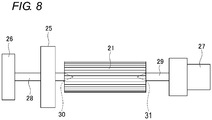
- a center pin 28 disposed on a front pressing jig 26, and a center pin 29 disposed on a back pressing jig 27 are firstly fitted into centering tapered holes 30, 31 which are disposed at the shaft centers of the end surfaces of a male spline shaft 21, and the male spline shaft 21 is clamped between the front pressing jig 26 and the back pressing jig 27, thereby supporting the male spline shaft 21.
- a cutting tool 25 includes blade portions which are formed in a female spline shape on the inner circumference.
- the blade portions are disposed on one end side in the axial direction, and directed toward the one end side.
- the male spline shaft 21 is forwardly moved together with the pressing jigs 26, 27 with respect to the cutting tool 25, and the resin layer which is formed on the male spline shaft 21 in a thicker manner is scratched off by the cutting tool 25, and finished so as to have a predetermined thickness. After the forward movement, the cutting tool 25 is pulled out from the male spline shaft 21.
- the document RU 2 385 786 C1 discloses a method for slotting and a ram for its realization.
- An aspect of the present invention is proposed in view of the above-described circumstances, and an object thereof is to provide a cutting tool in which, even when a male spline shaft has a portion which is provided in one end of the male spline shaft and which is larger in diameter than male splines, the male splines can be processed by forward and rearward moving the cutting tool, and a spline processing method in which the cutting tool is used. Further, another object is to provide a cutting tool which can accurately process male splines for a male spline shaft which does not have a portion which is provided in one end of the male spline shaft and which is larger in diameter than male splines, and a spline processing method in which the cutting tool is used.
- a first aspect of the invention provides a cylindrical cutting tool according to claim 1 for processing splines formed on an outer circumference of a shaft member extending in an axial direction.
- the cutting tool according to the first aspect of the invention includes blade portions which are formed in a spline shape on an inner circumference, wherein the blade portions include: a first blade portion which is formed in a terminal end portion in a first direction along the axial direction and which is directed substantially toward the first direction; and a second blade portion which is formed in a terminal end portion in a second direction along the axial direction and opposite to the first direction and which is directed substantially toward the second direction.
- the first blade portion is formed on the one end side of the cutting tool in the axial direction, and is directed toward the axial direction along which the splines are processed, and the second blade portion is formed on the other end side in the axial direction, and is directed toward the opposite axial direction along which the splines are processed. Therefore, the splines can be processed by forward and rearward movements. In a portion which, in the process in the forward movement, is sprung back and not cut in a predetermined manner, consequently, splines can be accurately finished in the process of the rearward movement.
- a second aspect of the invention provides a spline processing according to claim 2.
- This method includes placing the terminal end portion of the cutting tool according to the first aspect in the first direction so as to be coaxial with the shaft member and on a side of a starting end portion of the shaft member in the first direction; moving the cutting tool forwardly from the starting end portion in the first direction along the axial direction of the shaft member toward a terminal end portion, thereby performing a spline process on the shaft member by the first blade portion; and moving the cutting tool rearwardly from a side of a starting end portion in the second direction along the axial direction of the shaft member toward a terminal end portion, thereby performing the spline process on the shaft member by the second blade portion.
- splines can be processed, in a state where the shaft member and the cutting tool according to the first aspect are coaxially set, by forwardly and rearwardly moving the cutting tool in a first cutting step of forwardly moving the cutting tool from the one end side in the axial direction toward the other end, and performing a spline process by the first blade portions, and a second cutting step of rearwardly moving from the other end side in the axial direction toward the one end, and performing a spline process by second blade portions. Therefore, splines can be accurately processed.
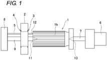
- Fig. 1 is a side view showing a spline process in an embodiment of the invention
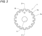
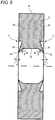
- Figs. 2 and 3 are front and side sectional views showing a male spline shaft 1 which is used in the spline process.
- the male spline shaft 1 will be described with reference to Figs. 2 and 3 .
- the male spline shaft 1 is a columnar shaft member which is made of a metal.
- a plurality of axial male spline tooth roots 1a are circumferentially placed on the outer circumference of the shaft member, and a resin layer 1b is molded thereon to form male splines.
- the surfaces of the male splines are formed by the resin layer 1b made of a nylon-based resin or the like.
- the thickness of the resin layer 1b is formed so as to be larger (for example, about 500 ⁇ m) than the required thickness (for example, about 100 to 200 ⁇ m).
- a centering tapered hole 11 is formed at the shaft center thereof, and a positioning tapered hole (positioning portion) 12 is formed radially outwardly from the shaft center.
- the spline processing apparatus includes: a front pressing jig 8 which is placed on one axial side of the male spline shaft 1, a back pressing jig 6 which is placed on the other axial side of the male spline shaft 1, and a cutting tool 2 which is to be moved in the axial direction of the male spline shaft 1 to perform the process.
- the front pressing jig 8 includes a center pin 9 and positioning pin 5 which have a tapered tip end portion
- the back pressing jig 6 includes a center pin 7 which has a tapered tip end portion.
- the center pin 9 is fitted into the centering tapered hole 11, and the center pin 7 is fitted into a centering tapered hole 13. According to this, the male spline shaft 1 and the cutting tool 2 are placed coaxially with each other.
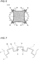
- the positioning tapered hole (positioning portion) 12 is fitted to the positioning pin 5, and the circumferential position of the spline shaft 1 with respect to the cutting tool 2 is determined so that, as shown in Fig. 7 , the teeth of the male splines are positioned in grooves 2b of the cutting tool 2 which will be described in detail later.
- Fig. 4 is a front view showing the cutting tool 2
- Fig. 5 is a sectional view of the cutting tool 2 taken along line A-A of Fig. 4
- Fig. 6 is a sectional view of the cutting tool 2 taken along line B-B of Fig. 4 .
- the cutting tool 2 is formed from a metal material which is suitable for cutting, such as alloy tool steel or high-speed tool steel, into a disk-like shape, and the inner circumference is formed into a spline-like shape.
- a metal material which is suitable for cutting such as alloy tool steel or high-speed tool steel
- projections 2a which have a trapezoidal sectional shape, and which are projected in the inner radial side are formed on the inner circumference, and a groove 2b having a trapezoidal sectional shape is formed between each pair of projections 2a.
- the projections 2a and the grooves 2b are disposed at regular intervals in the circumferential direction, and extend in the axial direction.
- the cutting tool 2 includes first blade portions 3 and second blade portions 4 in the both ends, i.e., the both ends of the projections 2a and the grooves 2b.
- the first blade portions 3 are formed on one axial end side of the projections 2a and the grooves 2b (in terminal end portions in a first direction along the shaft portion), while being directed toward approximately the one end (in approximately the first direction), and the second blade portions 4 are formed on the other end side of the projections 2a and the grooves 2b (in terminal end portions in a second direction opposite to the first direction), while being directed toward approximately the other end (in approximately the second direction).
- each of the first blade portions 3 is configured by: a biting portion 3a which is to bite the resin layer 1b; a finishing portion 3b which is to allow shavings of the resin layer 1b to escape; and a relief portion 3c which prevents contact with the resin layer 1b from occurring.
- the biting portion 3a is formed in a corner portion on the one end side of the projection 2a and the groove 2b, and has an acute angle.
- the finishing portion 3b is formed on the end surface of the one end side of the projection 2a and the groove 2b, and has surfaces which are inclined from the biting portion 3a by an inclination angle ⁇ in the outer radial direction or the circumferential direction.
- the inner radial side of the projection 2a, and that of the groove 2b have a surface which is inclined by the inclination angle ⁇ in the outer radial direction.
- the portion of the projection 2a on the side of the groove 2b has a surface which is inclined by the inclination angle ⁇ in the circumferential direction.
- the relief portion 3c is formed on the side surfaces of the projection 2a and the groove 2b, and has a surface which is inclined from the biting portion 3a by an inclination angle ⁇ in the axial direction.
- Each of the second blade portions 4 is configured by: a biting portion 4a which is to bite the resin layer 1b; a finishing portion 4b which is to allow shavings of the resin layer 1b to escape; and a relief portion 4c which prevents contact with the resin layer 1b from occurring.
- the biting portion 4a is formed in a corner portion on the other end side of the projection 2a and the groove 2b, and has an acute angle.
- the finishing portion 4b is formed on the end surface of the other end side of the projection 2a and the groove 2b, and has surfaces which are inclined from the biting portion 4a by the inclination angle ⁇ in the outer radial direction or the circumferential direction.
- the inner radial side of the projection 2a, and that of the groove 2b have a surface which is inclined by the inclination angle ⁇ in the outer radial direction.
- the portion of the projection 2a on the side of the groove 2b has a surface which is inclined by an inclination angle ⁇ in the circumferential direction.
- the relief portion 4c is formed on the side surfaces of the projection 2a and the groove 2b, and has a surface which is inclined from the biting portion 4a by the inclination angle ⁇ in the axial direction.
- the male spline shaft 1 is placed between the front pressing jig 8 and the back pressing jig 6, the center pin 9 of the front pressing jig 8 is fitted into the centering tapered hole 11, the center pin 7 of the back pressing jig 6 is fitted into the centering tapered hole 13, and the male spline shaft 1 and the cutting tool 2 are placed coaxially with each other.
- the positioning pin 5 is fitted into the positioning tapered hole (positioning portion) 12, and the circumferential position of the male spline shaft 1 with respect to the cutting tool 2 is determined so that the spline tooth roots 1a of the male spline shaft 1 are located in the grooves 2b of the cutting tool 2.
- the male spline shaft 1 is moved together with the front pressing jig 8 and the back pressing jig 6 toward the cutting tool 2 in the axial direction, and the male spline shaft 1 is passed into the cutting tool 2.
- An amount which, in the forward movement of the first cutting step, is sprung back and not cut is removed in the forward movement, and therefore the male splines can be accurately finished. Even when, in the male spline shaft 1, there is a portion that is larger in diameter than the male splines, the resin layer 1b is prevented from being scratched in the rearward movement, and the male splines can be processed.
- first blade portions 3 and the second blade portions 4 have the same shape and dimensions. In another embodiment, the first blade portions 3 and the second blade portions 4 may have different shapes and dimensions. For example, the portions may be different from each other in degree of the inclination angle ⁇ in the circumferential direction, and the inclination angle ⁇ in the axial direction. When the angles are well adjusted, the male splines may be more accurately finished.
Landscapes
- Engineering & Computer Science (AREA)
- Mechanical Engineering (AREA)
- Physics & Mathematics (AREA)
- Optics & Photonics (AREA)
- Milling Processes (AREA)
- Perforating, Stamping-Out Or Severing By Means Other Than Cutting (AREA)
Applications Claiming Priority (2)
| Application Number | Priority Date | Filing Date | Title |
|---|---|---|---|
| JP2013178863A JP6264784B2 (ja) | 2013-08-30 | 2013-08-30 | 切削工具 |
| PCT/JP2014/072882 WO2015030229A1 (ja) | 2013-08-30 | 2014-09-01 | 切削工具およびスプライン加工方法 |
Publications (3)
| Publication Number | Publication Date |
|---|---|
| EP3040147A1 EP3040147A1 (en) | 2016-07-06 |
| EP3040147A4 EP3040147A4 (en) | 2017-04-05 |
| EP3040147B1 true EP3040147B1 (en) | 2021-06-16 |
Family
ID=52586773
Family Applications (1)
| Application Number | Title | Priority Date | Filing Date |
|---|---|---|---|
| EP14840075.7A Active EP3040147B1 (en) | 2013-08-30 | 2014-09-01 | Cutting tool and spline processing method |
Country Status (5)
| Country | Link |
|---|---|
| US (1) | US9751140B2 (enExample) |
| EP (1) | EP3040147B1 (enExample) |
| JP (1) | JP6264784B2 (enExample) |
| CN (1) | CN105492151B (enExample) |
| WO (1) | WO2015030229A1 (enExample) |
Families Citing this family (6)
| Publication number | Priority date | Publication date | Assignee | Title |
|---|---|---|---|---|
| JP2018024062A (ja) * | 2016-08-10 | 2018-02-15 | 株式会社ジェイテクト | 歯切り工具および歯車加工方法 |
| US10618125B2 (en) * | 2016-07-01 | 2020-04-14 | Jtekt Corporation | Gear cutting tool, gear machining device, and gear machining method |
| CN107671344A (zh) * | 2017-08-09 | 2018-02-09 | 武汉船用机械有限责任公司 | 一种盲孔非标内花键的加工方法 |
| KR102266415B1 (ko) * | 2020-08-06 | 2021-06-17 | (주)서진엔지니어링 | 솔더펌핑유닛 및 이를 포함하는 솔더공급장치 |
| CN112620762B (zh) * | 2020-12-18 | 2024-12-13 | 贵州华烽电器有限公司 | 一种壳体键槽切削加工装置 |
| CN114749714A (zh) * | 2022-03-15 | 2022-07-15 | 绍兴前进齿轮箱有限公司 | 一种矩形内花键的加工方法 |
Family Cites Families (19)
| Publication number | Priority date | Publication date | Assignee | Title |
|---|---|---|---|---|
| US627099A (en) * | 1899-06-20 | Fourth to thomas sterling | ||
| US141006A (en) * | 1873-07-22 | Improvement in metal-planing machines | ||
| US1327881A (en) * | 1918-11-08 | 1920-01-13 | Carl H Roth | Tool or cutter head |
| US1466355A (en) * | 1920-07-31 | 1923-08-28 | Joseph D Dusenbury | Double cutting tool for planers |
| US2181810A (en) * | 1939-01-21 | 1939-11-28 | Owens Illinois Glass Co | Glass block trimmer |
| US2466197A (en) * | 1943-10-12 | 1949-04-05 | Berthiez Charles William | Toolholder |
| US3552014A (en) * | 1969-12-18 | 1971-01-05 | Henry Persson | Edge deburring tool |
| FR2580203B1 (fr) * | 1985-04-12 | 1987-08-28 | Usinor | Machine d'ebavurage de brames |
| DE3536949A1 (de) * | 1985-10-17 | 1987-04-23 | Mannesmann Ag | Verfahren und vorrichtung zum schnellanstellen der schneidstaehle einer bandkantenbearbeitungsmaschine |
| JPH0270341A (ja) * | 1988-08-31 | 1990-03-09 | Sumitomo Metal Ind Ltd | 鋼管製駆動軸の製造方法 |
| SU1764874A1 (ru) | 1990-03-29 | 1992-09-30 | Пермский машиностроительный завод им.В.И.Ленина | Способ нарезани наружных шлицев |
| JP2516702B2 (ja) | 1990-09-21 | 1996-07-24 | オーエスジー株式会社 | 溝加工用バイト |
| US5445050A (en) * | 1993-12-30 | 1995-08-29 | Owens; Michael R. | Hand-held ice skate blade sharpener tool |
| US6067880A (en) * | 1996-12-03 | 2000-05-30 | Arrigoni; John P. | Deburring device |
| JP3851101B2 (ja) * | 2001-03-08 | 2006-11-29 | 株式会社ジェイテクト | スプライン加工方法 |
| US20060130309A1 (en) | 2004-12-22 | 2006-06-22 | Torque-Traction Technologies, Inc. | Method of manufacturing a splined member having a coating of a material applied thereto |
| RU2385786C1 (ru) * | 2008-09-17 | 2010-04-10 | Юрий Михайлович Ермаков | Способ долбления и долбяк для его осуществления |
| JP2011110680A (ja) * | 2009-11-30 | 2011-06-09 | Nsk Ltd | スプライン加工方法及びスプラインシャフト |
| JP5836648B2 (ja) * | 2011-06-03 | 2015-12-24 | 株式会社Tjmデザイン | やすり |
-
2013
- 2013-08-30 JP JP2013178863A patent/JP6264784B2/ja not_active Expired - Fee Related
-
2014
- 2014-09-01 US US14/912,782 patent/US9751140B2/en not_active Expired - Fee Related
- 2014-09-01 CN CN201480047621.3A patent/CN105492151B/zh not_active Expired - Fee Related
- 2014-09-01 WO PCT/JP2014/072882 patent/WO2015030229A1/ja not_active Ceased
- 2014-09-01 EP EP14840075.7A patent/EP3040147B1/en active Active
Non-Patent Citations (1)
| Title |
|---|
| None * |
Also Published As
| Publication number | Publication date |
|---|---|
| EP3040147A4 (en) | 2017-04-05 |
| JP6264784B2 (ja) | 2018-01-24 |
| US20160193675A1 (en) | 2016-07-07 |
| US9751140B2 (en) | 2017-09-05 |
| CN105492151A (zh) | 2016-04-13 |
| JP2015047647A (ja) | 2015-03-16 |
| CN105492151B (zh) | 2018-03-09 |
| WO2015030229A1 (ja) | 2015-03-05 |
| EP3040147A1 (en) | 2016-07-06 |
Similar Documents
| Publication | Publication Date | Title |
|---|---|---|
| EP3040147B1 (en) | Cutting tool and spline processing method | |
| US7698924B2 (en) | Member having a chamfered through hole and manufacturing method of the same | |
| TWI577464B (zh) | 金屬端部剖面外周之加工方法、藉由該加工方法所獲得之金屬零件與其他構件之接合方法 | |
| JP5741138B2 (ja) | フランジ一体型波付管の製造方法、フランジ一体型波付管、および前記製造方法に用いられる波付管用の切断装置 | |
| US20040035000A1 (en) | Inner spline member and manufacturing method thereof | |
| CN101652202B (zh) | 花键构件的制造装置及制造方法 | |
| JP5958203B2 (ja) | ステアリング装置の製造方法 | |
| JP5768969B2 (ja) | 突起型前案内部を有するブローチ工具 | |
| WO2009125786A1 (ja) | 剪断加工方法 | |
| WO2007092775A2 (en) | Self-centering broach | |
| JP2000120649A (ja) | Frp製筒体と金属部品との接合方法及び軸部品 | |
| JP4862794B2 (ja) | スプライン部材の製造方法 | |
| JP4465483B2 (ja) | 金属製のパイプ部材に対する溝の加工装置 | |
| JP6699435B2 (ja) | 円筒状部材の製造方法 | |
| CN108472761B (zh) | 圆筒状构件的制造方法 | |
| JP2004092902A (ja) | 湿式バンドブレーキ用ブレーキドラムおよびその製造方法 | |
| JP5958204B2 (ja) | ステアリング装置の製造方法 | |
| JP5954062B2 (ja) | ステアリング装置及びその製造方法 | |
| JPS5828435A (ja) | 中空素材の製造方法 | |
| JP6702130B2 (ja) | 円筒状部材の製造方法 | |
| JP4173828B2 (ja) | 金属製薄板ドラムの切断装置 | |
| KR101898826B1 (ko) | 지그를 이용한 자동차 허브베어링 가공장치 | |
| KR20190028853A (ko) | 샤프트 조인트 제조방법 | |
| WO2017022147A1 (ja) | ブレーキディスクの製造方法 | |
| JP4673730B2 (ja) | ボス部材及びボス部材の製造方法 |
Legal Events
| Date | Code | Title | Description |
|---|---|---|---|
| PUAI | Public reference made under article 153(3) epc to a published international application that has entered the european phase |
Free format text: ORIGINAL CODE: 0009012 |
|
| 17P | Request for examination filed |
Effective date: 20160218 |
|
| AK | Designated contracting states |
Kind code of ref document: A1 Designated state(s): AL AT BE BG CH CY CZ DE DK EE ES FI FR GB GR HR HU IE IS IT LI LT LU LV MC MK MT NL NO PL PT RO RS SE SI SK SM TR |
|
| AX | Request for extension of the european patent |
Extension state: BA ME |
|
| DAX | Request for extension of the european patent (deleted) | ||
| A4 | Supplementary search report drawn up and despatched |
Effective date: 20170303 |
|
| RIC1 | Information provided on ipc code assigned before grant |
Ipc: B23D 1/18 20060101ALI20170224BHEP Ipc: B23F 21/06 20060101ALI20170224BHEP Ipc: B23F 1/04 20060101ALI20170224BHEP Ipc: B23D 13/00 20060101ALI20170224BHEP Ipc: B23D 79/12 20060101ALI20170224BHEP Ipc: B23D 1/08 20060101AFI20170224BHEP Ipc: B23D 1/26 20060101ALI20170224BHEP |
|
| REG | Reference to a national code |
Ref country code: DE Ref legal event code: R079 Ref document number: 602014078189 Country of ref document: DE Free format text: PREVIOUS MAIN CLASS: B23D0001260000 Ipc: B23D0001080000 |
|
| RIC1 | Information provided on ipc code assigned before grant |
Ipc: B23F 1/04 20060101ALI20201119BHEP Ipc: B23D 1/08 20060101AFI20201119BHEP Ipc: B23F 21/06 20060101ALI20201119BHEP Ipc: B23D 1/26 20060101ALI20201119BHEP Ipc: B23D 13/00 20060101ALI20201119BHEP Ipc: B23D 79/12 20060101ALI20201119BHEP Ipc: B23D 1/18 20060101ALI20201119BHEP |
|
| GRAP | Despatch of communication of intention to grant a patent |
Free format text: ORIGINAL CODE: EPIDOSNIGR1 |
|
| STAA | Information on the status of an ep patent application or granted ep patent |
Free format text: STATUS: GRANT OF PATENT IS INTENDED |
|
| INTG | Intention to grant announced |
Effective date: 20210112 |
|
| GRAS | Grant fee paid |
Free format text: ORIGINAL CODE: EPIDOSNIGR3 |
|
| GRAA | (expected) grant |
Free format text: ORIGINAL CODE: 0009210 |
|
| STAA | Information on the status of an ep patent application or granted ep patent |
Free format text: STATUS: THE PATENT HAS BEEN GRANTED |
|
| AK | Designated contracting states |
Kind code of ref document: B1 Designated state(s): AL AT BE BG CH CY CZ DE DK EE ES FI FR GB GR HR HU IE IS IT LI LT LU LV MC MK MT NL NO PL PT RO RS SE SI SK SM TR |
|
| RAP3 | Party data changed (applicant data changed or rights of an application transferred) |
Owner name: JTEKT CORPORATION |
|
| REG | Reference to a national code |
Ref country code: GB Ref legal event code: FG4D |
|
| RIN1 | Information on inventor provided before grant (corrected) |
Inventor name: IMAI, RYOUSUKE Inventor name: KANEUCHI, EIJI Inventor name: YAMADA, YOSHIMASA Inventor name: NABESHIMA, KOICHI |
|
| REG | Reference to a national code |
Ref country code: CH Ref legal event code: EP |
|
| REG | Reference to a national code |
Ref country code: DE Ref legal event code: R096 Ref document number: 602014078189 Country of ref document: DE Ref country code: AT Ref legal event code: REF Ref document number: 1401910 Country of ref document: AT Kind code of ref document: T Effective date: 20210715 |
|
| REG | Reference to a national code |
Ref country code: IE Ref legal event code: FG4D |
|
| REG | Reference to a national code |
Ref country code: LT Ref legal event code: MG9D |
|
| PG25 | Lapsed in a contracting state [announced via postgrant information from national office to epo] |
Ref country code: LT Free format text: LAPSE BECAUSE OF FAILURE TO SUBMIT A TRANSLATION OF THE DESCRIPTION OR TO PAY THE FEE WITHIN THE PRESCRIBED TIME-LIMIT Effective date: 20210616 Ref country code: FI Free format text: LAPSE BECAUSE OF FAILURE TO SUBMIT A TRANSLATION OF THE DESCRIPTION OR TO PAY THE FEE WITHIN THE PRESCRIBED TIME-LIMIT Effective date: 20210616 Ref country code: BG Free format text: LAPSE BECAUSE OF FAILURE TO SUBMIT A TRANSLATION OF THE DESCRIPTION OR TO PAY THE FEE WITHIN THE PRESCRIBED TIME-LIMIT Effective date: 20210916 Ref country code: HR Free format text: LAPSE BECAUSE OF FAILURE TO SUBMIT A TRANSLATION OF THE DESCRIPTION OR TO PAY THE FEE WITHIN THE PRESCRIBED TIME-LIMIT Effective date: 20210616 |
|
| REG | Reference to a national code |
Ref country code: AT Ref legal event code: MK05 Ref document number: 1401910 Country of ref document: AT Kind code of ref document: T Effective date: 20210616 |
|
| REG | Reference to a national code |
Ref country code: NL Ref legal event code: MP Effective date: 20210616 |
|
| PG25 | Lapsed in a contracting state [announced via postgrant information from national office to epo] |
Ref country code: NO Free format text: LAPSE BECAUSE OF FAILURE TO SUBMIT A TRANSLATION OF THE DESCRIPTION OR TO PAY THE FEE WITHIN THE PRESCRIBED TIME-LIMIT Effective date: 20210916 Ref country code: RS Free format text: LAPSE BECAUSE OF FAILURE TO SUBMIT A TRANSLATION OF THE DESCRIPTION OR TO PAY THE FEE WITHIN THE PRESCRIBED TIME-LIMIT Effective date: 20210616 Ref country code: SE Free format text: LAPSE BECAUSE OF FAILURE TO SUBMIT A TRANSLATION OF THE DESCRIPTION OR TO PAY THE FEE WITHIN THE PRESCRIBED TIME-LIMIT Effective date: 20210616 Ref country code: GR Free format text: LAPSE BECAUSE OF FAILURE TO SUBMIT A TRANSLATION OF THE DESCRIPTION OR TO PAY THE FEE WITHIN THE PRESCRIBED TIME-LIMIT Effective date: 20210917 Ref country code: LV Free format text: LAPSE BECAUSE OF FAILURE TO SUBMIT A TRANSLATION OF THE DESCRIPTION OR TO PAY THE FEE WITHIN THE PRESCRIBED TIME-LIMIT Effective date: 20210616 |
|
| PG25 | Lapsed in a contracting state [announced via postgrant information from national office to epo] |
Ref country code: EE Free format text: LAPSE BECAUSE OF FAILURE TO SUBMIT A TRANSLATION OF THE DESCRIPTION OR TO PAY THE FEE WITHIN THE PRESCRIBED TIME-LIMIT Effective date: 20210616 Ref country code: CZ Free format text: LAPSE BECAUSE OF FAILURE TO SUBMIT A TRANSLATION OF THE DESCRIPTION OR TO PAY THE FEE WITHIN THE PRESCRIBED TIME-LIMIT Effective date: 20210616 Ref country code: SM Free format text: LAPSE BECAUSE OF FAILURE TO SUBMIT A TRANSLATION OF THE DESCRIPTION OR TO PAY THE FEE WITHIN THE PRESCRIBED TIME-LIMIT Effective date: 20210616 Ref country code: SK Free format text: LAPSE BECAUSE OF FAILURE TO SUBMIT A TRANSLATION OF THE DESCRIPTION OR TO PAY THE FEE WITHIN THE PRESCRIBED TIME-LIMIT Effective date: 20210616 Ref country code: ES Free format text: LAPSE BECAUSE OF FAILURE TO SUBMIT A TRANSLATION OF THE DESCRIPTION OR TO PAY THE FEE WITHIN THE PRESCRIBED TIME-LIMIT Effective date: 20210616 Ref country code: RO Free format text: LAPSE BECAUSE OF FAILURE TO SUBMIT A TRANSLATION OF THE DESCRIPTION OR TO PAY THE FEE WITHIN THE PRESCRIBED TIME-LIMIT Effective date: 20210616 Ref country code: NL Free format text: LAPSE BECAUSE OF FAILURE TO SUBMIT A TRANSLATION OF THE DESCRIPTION OR TO PAY THE FEE WITHIN THE PRESCRIBED TIME-LIMIT Effective date: 20210616 Ref country code: PT Free format text: LAPSE BECAUSE OF FAILURE TO SUBMIT A TRANSLATION OF THE DESCRIPTION OR TO PAY THE FEE WITHIN THE PRESCRIBED TIME-LIMIT Effective date: 20211018 Ref country code: AT Free format text: LAPSE BECAUSE OF FAILURE TO SUBMIT A TRANSLATION OF THE DESCRIPTION OR TO PAY THE FEE WITHIN THE PRESCRIBED TIME-LIMIT Effective date: 20210616 |
|
| PG25 | Lapsed in a contracting state [announced via postgrant information from national office to epo] |
Ref country code: PL Free format text: LAPSE BECAUSE OF FAILURE TO SUBMIT A TRANSLATION OF THE DESCRIPTION OR TO PAY THE FEE WITHIN THE PRESCRIBED TIME-LIMIT Effective date: 20210616 |
|
| REG | Reference to a national code |
Ref country code: DE Ref legal event code: R097 Ref document number: 602014078189 Country of ref document: DE |
|
| RAP4 | Party data changed (patent owner data changed or rights of a patent transferred) |
Owner name: JTEKT CORPORATION |
|
| PLBE | No opposition filed within time limit |
Free format text: ORIGINAL CODE: 0009261 |
|
| STAA | Information on the status of an ep patent application or granted ep patent |
Free format text: STATUS: NO OPPOSITION FILED WITHIN TIME LIMIT |
|
| PG25 | Lapsed in a contracting state [announced via postgrant information from national office to epo] |
Ref country code: DK Free format text: LAPSE BECAUSE OF FAILURE TO SUBMIT A TRANSLATION OF THE DESCRIPTION OR TO PAY THE FEE WITHIN THE PRESCRIBED TIME-LIMIT Effective date: 20210616 |
|
| REG | Reference to a national code |
Ref country code: CH Ref legal event code: PL |
|
| REG | Reference to a national code |
Ref country code: BE Ref legal event code: MM Effective date: 20210930 |
|
| 26N | No opposition filed |
Effective date: 20220317 |
|
| GBPC | Gb: european patent ceased through non-payment of renewal fee |
Effective date: 20210916 |
|
| PG25 | Lapsed in a contracting state [announced via postgrant information from national office to epo] |
Ref country code: MC Free format text: LAPSE BECAUSE OF FAILURE TO SUBMIT A TRANSLATION OF THE DESCRIPTION OR TO PAY THE FEE WITHIN THE PRESCRIBED TIME-LIMIT Effective date: 20210616 Ref country code: AL Free format text: LAPSE BECAUSE OF FAILURE TO SUBMIT A TRANSLATION OF THE DESCRIPTION OR TO PAY THE FEE WITHIN THE PRESCRIBED TIME-LIMIT Effective date: 20210616 |
|
| PG25 | Lapsed in a contracting state [announced via postgrant information from national office to epo] |
Ref country code: LU Free format text: LAPSE BECAUSE OF NON-PAYMENT OF DUE FEES Effective date: 20210901 Ref country code: IT Free format text: LAPSE BECAUSE OF FAILURE TO SUBMIT A TRANSLATION OF THE DESCRIPTION OR TO PAY THE FEE WITHIN THE PRESCRIBED TIME-LIMIT Effective date: 20210616 Ref country code: IE Free format text: LAPSE BECAUSE OF NON-PAYMENT OF DUE FEES Effective date: 20210901 Ref country code: GB Free format text: LAPSE BECAUSE OF NON-PAYMENT OF DUE FEES Effective date: 20210916 Ref country code: BE Free format text: LAPSE BECAUSE OF NON-PAYMENT OF DUE FEES Effective date: 20210930 |
|
| PG25 | Lapsed in a contracting state [announced via postgrant information from national office to epo] |
Ref country code: LI Free format text: LAPSE BECAUSE OF NON-PAYMENT OF DUE FEES Effective date: 20210930 Ref country code: CH Free format text: LAPSE BECAUSE OF NON-PAYMENT OF DUE FEES Effective date: 20210930 |
|
| PG25 | Lapsed in a contracting state [announced via postgrant information from national office to epo] |
Ref country code: HU Free format text: LAPSE BECAUSE OF FAILURE TO SUBMIT A TRANSLATION OF THE DESCRIPTION OR TO PAY THE FEE WITHIN THE PRESCRIBED TIME-LIMIT; INVALID AB INITIO Effective date: 20140901 |
|
| PG25 | Lapsed in a contracting state [announced via postgrant information from national office to epo] |
Ref country code: CY Free format text: LAPSE BECAUSE OF FAILURE TO SUBMIT A TRANSLATION OF THE DESCRIPTION OR TO PAY THE FEE WITHIN THE PRESCRIBED TIME-LIMIT Effective date: 20210616 |
|
| PGFP | Annual fee paid to national office [announced via postgrant information from national office to epo] |
Ref country code: FR Payment date: 20230808 Year of fee payment: 10 Ref country code: DE Payment date: 20230802 Year of fee payment: 10 |
|
| PG25 | Lapsed in a contracting state [announced via postgrant information from national office to epo] |
Ref country code: MK Free format text: LAPSE BECAUSE OF FAILURE TO SUBMIT A TRANSLATION OF THE DESCRIPTION OR TO PAY THE FEE WITHIN THE PRESCRIBED TIME-LIMIT Effective date: 20210616 |
|
| PG25 | Lapsed in a contracting state [announced via postgrant information from national office to epo] |
Ref country code: TR Free format text: LAPSE BECAUSE OF FAILURE TO SUBMIT A TRANSLATION OF THE DESCRIPTION OR TO PAY THE FEE WITHIN THE PRESCRIBED TIME-LIMIT Effective date: 20210616 |
|
| PG25 | Lapsed in a contracting state [announced via postgrant information from national office to epo] |
Ref country code: MT Free format text: LAPSE BECAUSE OF FAILURE TO SUBMIT A TRANSLATION OF THE DESCRIPTION OR TO PAY THE FEE WITHIN THE PRESCRIBED TIME-LIMIT Effective date: 20210616 |
|
| REG | Reference to a national code |
Ref country code: DE Ref legal event code: R119 Ref document number: 602014078189 Country of ref document: DE |
|
| PG25 | Lapsed in a contracting state [announced via postgrant information from national office to epo] |
Ref country code: DE Free format text: LAPSE BECAUSE OF NON-PAYMENT OF DUE FEES Effective date: 20250401 |
|
| PG25 | Lapsed in a contracting state [announced via postgrant information from national office to epo] |
Ref country code: FR Free format text: LAPSE BECAUSE OF NON-PAYMENT OF DUE FEES Effective date: 20240930 |