WO2015030229A1 - 切削工具およびスプライン加工方法 - Google Patents
切削工具およびスプライン加工方法 Download PDFInfo
- Publication number
- WO2015030229A1 WO2015030229A1 PCT/JP2014/072882 JP2014072882W WO2015030229A1 WO 2015030229 A1 WO2015030229 A1 WO 2015030229A1 JP 2014072882 W JP2014072882 W JP 2014072882W WO 2015030229 A1 WO2015030229 A1 WO 2015030229A1
- Authority
- WO
- WIPO (PCT)
- Prior art keywords
- cutting tool
- spline
- male spline
- end side
- shaft
- Prior art date
- Legal status (The legal status is an assumption and is not a legal conclusion. Google has not performed a legal analysis and makes no representation as to the accuracy of the status listed.)
- Ceased
Links
Images


Classifications
-
- B—PERFORMING OPERATIONS; TRANSPORTING
- B23—MACHINE TOOLS; METAL-WORKING NOT OTHERWISE PROVIDED FOR
- B23D—PLANING; SLOTTING; SHEARING; BROACHING; SAWING; FILING; SCRAPING; LIKE OPERATIONS FOR WORKING METAL BY REMOVING MATERIAL, NOT OTHERWISE PROVIDED FOR
- B23D79/00—Methods, machines, or devices not covered elsewhere, for working metal by removal of material
- B23D79/12—Machines or devices for peeling bars or tubes making use of cutting bits arranged around the workpiece, otherwise than by turning
-
- B—PERFORMING OPERATIONS; TRANSPORTING
- B23—MACHINE TOOLS; METAL-WORKING NOT OTHERWISE PROVIDED FOR
- B23D—PLANING; SLOTTING; SHEARING; BROACHING; SAWING; FILING; SCRAPING; LIKE OPERATIONS FOR WORKING METAL BY REMOVING MATERIAL, NOT OTHERWISE PROVIDED FOR
- B23D1/00—Planing or slotting machines cutting by relative movement of the tool and workpiece in a horizontal straight line only
- B23D1/08—Planing or slotting machines cutting by relative movement of the tool and workpiece in a horizontal straight line only by movement of the tool
-
- B—PERFORMING OPERATIONS; TRANSPORTING
- B23—MACHINE TOOLS; METAL-WORKING NOT OTHERWISE PROVIDED FOR
- B23D—PLANING; SLOTTING; SHEARING; BROACHING; SAWING; FILING; SCRAPING; LIKE OPERATIONS FOR WORKING METAL BY REMOVING MATERIAL, NOT OTHERWISE PROVIDED FOR
- B23D1/00—Planing or slotting machines cutting by relative movement of the tool and workpiece in a horizontal straight line only
- B23D1/18—Planing or slotting machines cutting by relative movement of the tool and workpiece in a horizontal straight line only cutting on both the forward and the return stroke
-
- B—PERFORMING OPERATIONS; TRANSPORTING
- B23—MACHINE TOOLS; METAL-WORKING NOT OTHERWISE PROVIDED FOR
- B23D—PLANING; SLOTTING; SHEARING; BROACHING; SAWING; FILING; SCRAPING; LIKE OPERATIONS FOR WORKING METAL BY REMOVING MATERIAL, NOT OTHERWISE PROVIDED FOR
- B23D1/00—Planing or slotting machines cutting by relative movement of the tool and workpiece in a horizontal straight line only
- B23D1/20—Planing or slotting machines cutting by relative movement of the tool and workpiece in a horizontal straight line only with tool-supports or work-supports specially mounted or guided for working in different directions or at different angles; Special purpose machines
- B23D1/26—Planing or slotting machines cutting by relative movement of the tool and workpiece in a horizontal straight line only with tool-supports or work-supports specially mounted or guided for working in different directions or at different angles; Special purpose machines for planing edges or ridges or cutting grooves
-
- B—PERFORMING OPERATIONS; TRANSPORTING
- B23—MACHINE TOOLS; METAL-WORKING NOT OTHERWISE PROVIDED FOR
- B23D—PLANING; SLOTTING; SHEARING; BROACHING; SAWING; FILING; SCRAPING; LIKE OPERATIONS FOR WORKING METAL BY REMOVING MATERIAL, NOT OTHERWISE PROVIDED FOR
- B23D13/00—Tools or tool holders specially designed for planing or slotting machines
- B23D13/005—Tools or tool holders adapted to operate in both the forward and return stroke
-
- B—PERFORMING OPERATIONS; TRANSPORTING
- B23—MACHINE TOOLS; METAL-WORKING NOT OTHERWISE PROVIDED FOR
- B23F—MAKING GEARS OR TOOTHED RACKS
- B23F1/00—Making gear teeth by tools of which the profile matches the profile of the required surface
- B23F1/04—Making gear teeth by tools of which the profile matches the profile of the required surface by planing or slotting
-
- B—PERFORMING OPERATIONS; TRANSPORTING
- B23—MACHINE TOOLS; METAL-WORKING NOT OTHERWISE PROVIDED FOR
- B23F—MAKING GEARS OR TOOTHED RACKS
- B23F21/00—Tools specially adapted for use in machines for manufacturing gear teeth
- B23F21/04—Planing or slotting tools
- B23F21/06—Planing or slotting tools having a profile which matches a gear tooth profile
Definitions
- An aspect of the present invention relates to a cutting tool for processing a spline on a spline shaft and a spline processing method using the cutting tool.
- the steering shaft of an automobile steering system is required to absorb the axial displacement that occurs when the vehicle travels and to transmit the displacement and vibration on the steering wheel. Further, in order to obtain an optimum position for the driver to drive the automobile, a function of moving the position of the steering wheel in the axial direction and adjusting the position is required. In any of these cases, the steering shaft is required to reduce rattling noise, to reduce the rattling on the steering wheel, and to reduce the sliding resistance during the axial sliding operation. .
- the steering shaft is configured such that a male spline shaft on which a male spline is formed and a female spline shaft on which a female spline is formed are non-rotatably and slidably fitted.
- a male spline shaft has a male spline formed by arranging a male spline root in the axial direction on the outer periphery of a cylindrical shaft member in the circumferential direction, and molding a resin layer with excellent slidability thereon. ing.
- the resin layer is formed with a large thickness and then finished to a predetermined thickness by cutting or the like.
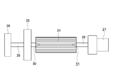
- center pins provided on the front-side holding jig 26 are inserted into center positioning taper holes 30 and 31 provided at the axial centers of both end faces of the male spline shaft 21.
- the male spline shaft 21 is supported by fitting the center pin 29 provided on the front side 28 and the back side holding jig 27 and sandwiching the male spline shaft 21 by the front side holding jig 26 and the back side holding jig 27. To do.
- the cutting tool 25 includes a blade portion formed in a female spline shape on the inner periphery, and the blade portion is provided on one end side in the axial direction and is directed to one end side.
- the male spline shaft 21 is moved forward together with the holding jigs 26 and 27 with respect to the cutting tool 25, and the resin layer formed thick on the male spline shaft 21 is scraped off by the cutting tool 25 and has a predetermined film thickness. Finished. After the forward movement, the cutting tool 25 is extracted from the male spline shaft 21.
- some male spline shafts have a part having a workpiece maximum diameter larger than that of the male spline at one end, and those having a shape cannot cut the cutting tool after the forward movement. Therefore, it is necessary to pass the cutting tool again through the portion processed by the backward movement and remove the cutting tool. Since the cutting tool has a blade portion only on one side in the processing direction, the amount of the resin layer that could not be cut as defined by the spring back in the forward processing is peeled off. Therefore, it cannot be applied to a male spline shaft in which a portion having a diameter larger than that of the male spline is present at one end.
- the aspect of the present invention has been proposed in view of the above circumstances, and even if the male spline shaft has a larger diameter than the male spline at one end, the cutting tool is reciprocated to process the male spline. It is an object of the present invention to provide a cutting tool that can be used and a spline processing method using the cutting tool. Furthermore, it aims at providing the spline processing method using the cutting tool which can process a male spline accurately with respect to the male spline shaft which does not have a part larger in diameter than a male spline at one end, and the cutting tool. .
- 1st aspect of this invention is a cylindrical cutting tool which processes the spline formed in the axial direction on the outer periphery of the shaft member, Comprising:
- the said blade part is equipped with the blade part formed in the inner periphery at the spline shape, Is a first blade portion formed substantially in the first direction at a terminal end portion in the first direction along the axial direction, and a second opposite to the first direction along the axial direction.
- the gist of the present invention is a cutting tool including a second blade portion formed substantially in the second direction at the end portion of the direction.
- the first blade portion is formed on the cutting tool for processing the spline on the one axial end side of the cutting tool in the axial direction for processing the spline, and the other axial end side is formed. Since the second blade portion is formed in the opposite axial direction for processing the spline, the spline can be processed by reciprocating motion. Therefore, it is possible to finish the spline with high accuracy by reciprocating the portion that could not be cut as it was spring-backed during the forward operation.
- the end portion in the first direction of the cutting tool according to the first aspect is arranged coaxially with the shaft member and on the start end side in the first direction of the shaft member.
- the cutting tool is moved forward from the start end side in the first direction in the axial direction of the shaft member toward the end end side, and the shaft member is splined by the first blade portion, and the cutting tool
- the main point is a spline processing method in which the shaft member is moved backward from the start end side in the second direction of the shaft member toward the end end side, and the shaft member is splined by the second blade portion.
- the shaft member in a state where the shaft member and the cutting tool according to the first aspect are set coaxially, the shaft member is moved forward from one end side to the other end side in the axial direction, and the first The cutting tool is formed by a first cutting step in which spline processing is performed with the blade portion and a second cutting step in which spline processing is performed with the second blade portion being moved backward from the other end side in the axial direction to the one end side. Since it can be reciprocated and splined, it can be splined with high accuracy.
- the resin layer does not peel off, so that the male spline can be processed with respect to the male spline shaft having a larger diameter at one end than the male spline.
- a cutting tool that can be used and a spline processing method that uses the cutting tool can be provided. Furthermore, it is possible to provide a cutting tool capable of machining a male spline with high accuracy and a spline machining method using the cutting tool for a male spline shaft that does not have a portion having a diameter larger than that of the male spline at one end.
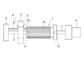
- FIG. 1 is a side view showing a spline cutting process according to an embodiment of the present invention.
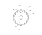
- FIG. 2 is a front sectional view showing a male spline shaft to be splined according to an embodiment of the present invention.
- FIG. 3 is a ZZ cross-sectional view of FIG. 2 according to one embodiment of the present invention.
- FIG. 4 is a front view of a cutting tool according to an embodiment of the present invention.
- 5 is a cross-sectional view taken along line AA of FIG. 4 according to an embodiment of the present invention.
- 6 is a cross-sectional view taken along the line BB of FIG. 4 according to an embodiment of the present invention.
- FIG. 7 is an explanatory view showing the positional relationship between the teeth of the male spline shaft and the blade of the cutting tool according to one embodiment of the present invention.
- FIG. 8 is a side view showing cutting of the background art.
- FIG. 1 is a side view for illustrating spline processing according to an embodiment of the present invention
- FIGS. 2 and 3 are a front view and a side sectional view showing a male spline shaft 1 used in the spline processing.
- the male spline shaft 1 will be described with reference to FIGS.
- the male spline shaft 1 is a metal columnar shaft member.
- a plurality of axial spline teeth 1a are arranged in the circumferential direction on the outer periphery of the shaft member, and a resin layer 1b is molded thereon, A male spline is formed.
- the male spline surface is formed of a resin layer 1b made of nylon resin or the like, and here, the resin layer 1b is formed thicker (for example, about 500 ⁇ m) than the required film thickness (for example, about 100 to 200 ⁇ m). .
- a center positioning taper hole 11 is formed at the center of the shaft, and a positioning taper hole (positioning portion) 12 is formed radially outward from the center of the shaft.
- the spline processing apparatus includes a front side pressing jig 8 disposed on one side in the axial direction of the male spline shaft 1, a back side pressing jig 6 disposed on the other side in the axial direction of the male spline shaft 1, and a male And a cutting tool 2 that moves and processes in the axial direction of the spline shaft 1.
- the front-side pressing jig 8 includes a center pin 9 and a positioning pin 5 having a tapered tip portion
- the back-side pressing jig 6 includes a center pin 7 having a tapered tip portion.
- the center pin 9 is fitted into the center positioning taper hole 11, and the center pin 7 is fitted into the center positioning taper hole 13.
- the male spline shaft 1 and the cutting tool 2 are arranged coaxially.
- the positioning taper hole (positioning portion) 12 is fitted to the positioning pin 5 and is attached to the cutting tool 2 so that the teeth of the male spline are positioned in the groove portion 2b of the cutting tool 2 described in detail later as shown in FIG.
- the circumferential position of the spline shaft 1 is determined.
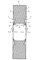
- FIG. 4 is a front view showing the cutting tool 2.
- 5 is a cross-sectional view of the cutting tool 2 taken along line AA in FIG. 4
- FIG. 6 is a cross-sectional view of the cutting tool 2 taken along line BB in FIG.
- the cutting tool 2 is formed in a disc shape from a metal material such as alloy tool steel or high-speed tool steel suitable for cutting, and is formed in a spline shape on the inner periphery.
- a protrusion 2a having a trapezoidal cross section is formed on the inner periphery so as to protrude toward the inner diameter side, and a groove 2b having a trapezoidal cross section is formed between the pair of protrusions 2a.
- the protrusion 2a and the groove 2b are provided at equal intervals in the circumferential direction and extend in the axial direction.
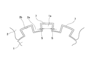
- the cutting tool 2 includes a first blade portion 3 and a second blade portion 4 at both ends, that is, both ends of the protruding portion 2a and the groove portion 2b.
- the first blade portion 3 is formed toward one end side (substantially in the first direction) on one end side in the axial direction of the protruding portion 2a and the groove portion 2b (end portion in the first direction along the shaft portion),
- the 2nd blade part 4 is formed toward the other end side (substantially 2nd direction) by the other end side (terminal part of the 2nd direction opposite to a 1st direction) of the protrusion part 2a and the groove part 2b. Yes.
- the first blade portion 3 has a biting portion 3 a that bites into the resin layer 1 b, a finish portion 3 b that escapes shavings of the resin layer 1 b, and a clearance that avoids contact with the resin layer 1 b. It is comprised with the part 3c.
- the biting portion 3a is formed at a corner portion on one end side of the protruding portion 2a and the groove portion 2b and has an acute angle.
- the finishing portion 3b is formed on the end surface on one end side of the protruding portion 2a and the groove portion 2b, and has a surface that is inclined from the biting portion 3a with an inclination angle ⁇ in the outer diameter direction or the circumferential direction.
- the inner diameter side of the protruding portion 2a and the inner diameter side of the groove portion 2b have surfaces inclined at an inclination angle ⁇ in the outer diameter direction.
- the groove 2b side of the projecting portion 2a has a surface inclined at an inclination angle ⁇ in the circumferential direction.
- the relief portion 3c is formed on the side surfaces of the protruding portion 2a and the groove portion 2b, and has a surface that is inclined in the axial direction from the biting portion 3a with an inclination angle ⁇ .
- the second blade portion 4 is composed of a biting portion 4a that bites into the resin layer 1b, a finishing portion 4b that allows the shavings of the resin layer 1b to escape, and a clearance portion 4c that avoids contact with the resin layer 1b.
- the biting portion 4a is formed at a corner portion on the other end side of the protruding portion 2a and the groove portion 2b and has an acute angle.
- the finishing part 4b is formed on the end face on the other end side of the protruding part 2a and the groove part 2b, and has a surface inclined from the biting part 4a in the outer diameter direction or the circumferential direction with an inclination angle ⁇ .
- the inner diameter side of the protruding portion 2a and the inner diameter side of the groove portion 2b have surfaces that are inclined at an inclination angle ⁇ in the outer diameter direction.
- the groove 2b side of the projecting portion 2a has a surface that is inclined at an inclination angle ⁇ in the circumferential direction.
- the relief portion 4c is formed on the side surfaces of the protruding portion 2a and the groove portion 2b, and has a surface inclined in the axial direction from the biting portion 4a as an inclination angle ⁇ .
- the male spline shaft 1 is disposed between the front-side pressing jig 8 and the rear-side pressing jig 6, and the center pin 9 of the front-side pressing jig 8 is fitted into the center positioning taper hole 11, so that the rear-side pressing jig is
- the center pin 7 of 6 is fitted into the center positioning taper hole 13, and the male spline shaft 1 and the cutting tool 2 are arranged coaxially.
- the positioning pin 5 is fitted into the positioning taper hole (positioning portion) 12, and the circumferential direction of the male spline shaft 1 relative to the cutting tool 2 is such that the spline root 1 a of the male spline shaft 1 is positioned in the groove 2 b of the cutting tool 2. Determine the position.
- the male spline shaft 1 is moved to the cutting tool 2 side in the axial direction together with the front-side pressing jig 8 and the rear-side pressing jig 6, and the male spline shaft 1 is passed through the cutting tool 2.
- the biting portion 3a of the first blade portion 3 is bitten on the resin layer 1b of the male spline shaft 1, and the cutting direction starting end side along the axial direction of the male spline shaft 1 is directed toward the cutting direction end side ( Part of the resin layer 1b is removed and the male spline is processed in the first cutting step in which it moves forward (from the start end side to the end end side in the first direction).
- the biting portion 4a of the second blade portion 4 is bitten on the resin layer 1b of the male spline shaft 1, and is directed from the cutting direction end side toward the cutting direction start end side (from the start end side in the second direction).
- Part of the resin layer 1b is removed and the male spline is finished in the second cutting step to be moved backward (toward the end portion side). Since the amount that could not be processed by springback in the forward movement of the first cutting process is removed by forward movement, the male spline can be finished with high accuracy. Even when the male spline shaft 1 has a portion having a diameter larger than that of the male spline, the resin layer 1b is not peeled back and the male spline can be processed.
- the male spline shaft 1 is removed from the front side holding jig 8 and the rear side holding jig 6 to complete the spline processing.
- first blade portion 3 and the second blade portion 4 have the same shape and the same dimensions. In other embodiments, the first blade portion 3 and the second blade portion 4 may have different shapes and different dimensions. For example, the inclination angle ⁇ in the circumferential direction and the inclination angle ⁇ in the axial direction may be different. If you adjust well, you can finish more accurately.
- SYMBOLS 1 Male spline shaft, 1a ... Spline tooth root, 1b ... Resin layer, 2 ... Cutting tool, 3 ... 1st blade part, 4 ... 2nd blade part, 5 ... Positioning pin, 6 ... Back side holding jig , 8 ... Front side holding jig, 7, 9 ... Center pin, 12 ... Taper hole for positioning, 11, 13 ... Taper hole for center positioning
Landscapes
- Engineering & Computer Science (AREA)
- Mechanical Engineering (AREA)
- Physics & Mathematics (AREA)
- Optics & Photonics (AREA)
- Milling Processes (AREA)
- Perforating, Stamping-Out Or Severing By Means Other Than Cutting (AREA)
Priority Applications (3)
| Application Number | Priority Date | Filing Date | Title |
|---|---|---|---|
| US14/912,782 US9751140B2 (en) | 2013-08-30 | 2014-09-01 | Cutting tool and spline processing method |
| CN201480047621.3A CN105492151B (zh) | 2013-08-30 | 2014-09-01 | 切削工具及花键加工方法 |
| EP14840075.7A EP3040147B1 (en) | 2013-08-30 | 2014-09-01 | Cutting tool and spline processing method |
Applications Claiming Priority (2)
| Application Number | Priority Date | Filing Date | Title |
|---|---|---|---|
| JP2013178863A JP6264784B2 (ja) | 2013-08-30 | 2013-08-30 | 切削工具 |
| JP2013-178863 | 2013-08-30 |
Publications (1)
| Publication Number | Publication Date |
|---|---|
| WO2015030229A1 true WO2015030229A1 (ja) | 2015-03-05 |
Family
ID=52586773
Family Applications (1)
| Application Number | Title | Priority Date | Filing Date |
|---|---|---|---|
| PCT/JP2014/072882 Ceased WO2015030229A1 (ja) | 2013-08-30 | 2014-09-01 | 切削工具およびスプライン加工方法 |
Country Status (5)
| Country | Link |
|---|---|
| US (1) | US9751140B2 (enExample) |
| EP (1) | EP3040147B1 (enExample) |
| JP (1) | JP6264784B2 (enExample) |
| CN (1) | CN105492151B (enExample) |
| WO (1) | WO2015030229A1 (enExample) |
Cited By (1)
| Publication number | Priority date | Publication date | Assignee | Title |
|---|---|---|---|---|
| CN114749714A (zh) * | 2022-03-15 | 2022-07-15 | 绍兴前进齿轮箱有限公司 | 一种矩形内花键的加工方法 |
Families Citing this family (5)
| Publication number | Priority date | Publication date | Assignee | Title |
|---|---|---|---|---|
| JP2018024062A (ja) * | 2016-08-10 | 2018-02-15 | 株式会社ジェイテクト | 歯切り工具および歯車加工方法 |
| US10618125B2 (en) * | 2016-07-01 | 2020-04-14 | Jtekt Corporation | Gear cutting tool, gear machining device, and gear machining method |
| CN107671344A (zh) * | 2017-08-09 | 2018-02-09 | 武汉船用机械有限责任公司 | 一种盲孔非标内花键的加工方法 |
| KR102266415B1 (ko) * | 2020-08-06 | 2021-06-17 | (주)서진엔지니어링 | 솔더펌핑유닛 및 이를 포함하는 솔더공급장치 |
| CN112620762B (zh) * | 2020-12-18 | 2024-12-13 | 贵州华烽电器有限公司 | 一种壳体键槽切削加工装置 |
Citations (4)
| Publication number | Priority date | Publication date | Assignee | Title |
|---|---|---|---|---|
| JPH0270341A (ja) * | 1988-08-31 | 1990-03-09 | Sumitomo Metal Ind Ltd | 鋼管製駆動軸の製造方法 |
| JP2002263951A (ja) | 2001-03-08 | 2002-09-17 | Koyo Seiko Co Ltd | スプライン加工方法 |
| JP2011110680A (ja) * | 2009-11-30 | 2011-06-09 | Nsk Ltd | スプライン加工方法及びスプラインシャフト |
| JP2012250322A (ja) * | 2011-06-03 | 2012-12-20 | Tjm Design Corp | やすり |
Family Cites Families (15)
| Publication number | Priority date | Publication date | Assignee | Title |
|---|---|---|---|---|
| US627099A (en) * | 1899-06-20 | Fourth to thomas sterling | ||
| US141006A (en) * | 1873-07-22 | Improvement in metal-planing machines | ||
| US1327881A (en) * | 1918-11-08 | 1920-01-13 | Carl H Roth | Tool or cutter head |
| US1466355A (en) * | 1920-07-31 | 1923-08-28 | Joseph D Dusenbury | Double cutting tool for planers |
| US2181810A (en) * | 1939-01-21 | 1939-11-28 | Owens Illinois Glass Co | Glass block trimmer |
| US2466197A (en) * | 1943-10-12 | 1949-04-05 | Berthiez Charles William | Toolholder |
| US3552014A (en) * | 1969-12-18 | 1971-01-05 | Henry Persson | Edge deburring tool |
| FR2580203B1 (fr) * | 1985-04-12 | 1987-08-28 | Usinor | Machine d'ebavurage de brames |
| DE3536949A1 (de) * | 1985-10-17 | 1987-04-23 | Mannesmann Ag | Verfahren und vorrichtung zum schnellanstellen der schneidstaehle einer bandkantenbearbeitungsmaschine |
| SU1764874A1 (ru) | 1990-03-29 | 1992-09-30 | Пермский машиностроительный завод им.В.И.Ленина | Способ нарезани наружных шлицев |
| JP2516702B2 (ja) | 1990-09-21 | 1996-07-24 | オーエスジー株式会社 | 溝加工用バイト |
| US5445050A (en) * | 1993-12-30 | 1995-08-29 | Owens; Michael R. | Hand-held ice skate blade sharpener tool |
| US6067880A (en) * | 1996-12-03 | 2000-05-30 | Arrigoni; John P. | Deburring device |
| US20060130309A1 (en) * | 2004-12-22 | 2006-06-22 | Torque-Traction Technologies, Inc. | Method of manufacturing a splined member having a coating of a material applied thereto |
| RU2385786C1 (ru) * | 2008-09-17 | 2010-04-10 | Юрий Михайлович Ермаков | Способ долбления и долбяк для его осуществления |
-
2013
- 2013-08-30 JP JP2013178863A patent/JP6264784B2/ja not_active Expired - Fee Related
-
2014
- 2014-09-01 CN CN201480047621.3A patent/CN105492151B/zh not_active Expired - Fee Related
- 2014-09-01 US US14/912,782 patent/US9751140B2/en not_active Expired - Fee Related
- 2014-09-01 WO PCT/JP2014/072882 patent/WO2015030229A1/ja not_active Ceased
- 2014-09-01 EP EP14840075.7A patent/EP3040147B1/en active Active
Patent Citations (4)
| Publication number | Priority date | Publication date | Assignee | Title |
|---|---|---|---|---|
| JPH0270341A (ja) * | 1988-08-31 | 1990-03-09 | Sumitomo Metal Ind Ltd | 鋼管製駆動軸の製造方法 |
| JP2002263951A (ja) | 2001-03-08 | 2002-09-17 | Koyo Seiko Co Ltd | スプライン加工方法 |
| JP2011110680A (ja) * | 2009-11-30 | 2011-06-09 | Nsk Ltd | スプライン加工方法及びスプラインシャフト |
| JP2012250322A (ja) * | 2011-06-03 | 2012-12-20 | Tjm Design Corp | やすり |
Cited By (1)
| Publication number | Priority date | Publication date | Assignee | Title |
|---|---|---|---|---|
| CN114749714A (zh) * | 2022-03-15 | 2022-07-15 | 绍兴前进齿轮箱有限公司 | 一种矩形内花键的加工方法 |
Also Published As
| Publication number | Publication date |
|---|---|
| JP6264784B2 (ja) | 2018-01-24 |
| CN105492151A (zh) | 2016-04-13 |
| EP3040147B1 (en) | 2021-06-16 |
| CN105492151B (zh) | 2018-03-09 |
| US20160193675A1 (en) | 2016-07-07 |
| EP3040147A4 (en) | 2017-04-05 |
| EP3040147A1 (en) | 2016-07-06 |
| JP2015047647A (ja) | 2015-03-16 |
| US9751140B2 (en) | 2017-09-05 |
Similar Documents
| Publication | Publication Date | Title |
|---|---|---|
| WO2015030229A1 (ja) | 切削工具およびスプライン加工方法 | |
| KR102253535B1 (ko) | 스탬핑된 부품을 제조하기 위한 방법 | |
| US10562138B2 (en) | Method for manufacturing rack bar | |
| CN103189263A (zh) | 转向柱及其制造方法 | |
| KR20060116099A (ko) | 자동차용 유니버셜 조인트 및 그 제조방법 | |
| JP5360624B2 (ja) | 粉末冶金で製造される変速機用滑りスリーブの内歯の製造方法 | |
| US10883533B2 (en) | Method of manufacturing spline telescopic shaft | |
| JP2006308090A (ja) | 等速ジョイントのボールハブを製造するための方法 | |
| JP6409101B2 (ja) | 加工工具、特に、ロール工具、および、円筒形の摺動面を加工する方法 | |
| JP2008200684A (ja) | 軸部材のスプライン形成方法 | |
| JP5857770B2 (ja) | ウォームホイールの製造方法及びウォームホイールの製造装置 | |
| JP5768969B2 (ja) | 突起型前案内部を有するブローチ工具 | |
| KR200458880Y1 (ko) | 6속 자동 변속기의 일방향 클러치 이너레이스용 피니셔 단계 하부 스플라인 몸체 단조물 | |
| JP5544655B2 (ja) | 打抜き加工方法、プレス成形品の製造方法、打抜き加工用金型およびプレス成形品 | |
| JP4133767B2 (ja) | ローリングツール | |
| JP5708552B2 (ja) | 無段変速機のバリエータ部品製造方法及びこの方法で使用するハードブローチ工具 | |
| KR20190028853A (ko) | 샤프트 조인트 제조방법 | |
| JP2009220261A (ja) | 内歯歯車加工用ヘリカルブローチ及びブローチ加工方法 | |
| CN113015586A (zh) | 用于在工件上制造滚珠滚道的方法和具有由此制造的滚珠滚道的滚珠丝杠螺母 | |
| CN110073122B (zh) | 用于制造盘片载体的方法 | |
| CN111097975A (zh) | 用于制造正齿轮制齿的工件的方法以及正齿轮制齿的工件 | |
| JP4650632B2 (ja) | 歯車構造及びピニオンギヤ | |
| JP2010043668A (ja) | 等速自在継手およびその製造方法 | |
| JP2009192058A (ja) | ウォームホイールおよびその製造方法 | |
| JP4638302B2 (ja) | 冷間鍛造傘歯車 |
Legal Events
| Date | Code | Title | Description |
|---|---|---|---|
| WWE | Wipo information: entry into national phase |
Ref document number: 201480047621.3 Country of ref document: CN |
|
| 121 | Ep: the epo has been informed by wipo that ep was designated in this application |
Ref document number: 14840075 Country of ref document: EP Kind code of ref document: A1 |
|
| REEP | Request for entry into the european phase |
Ref document number: 2014840075 Country of ref document: EP |
|
| WWE | Wipo information: entry into national phase |
Ref document number: 14912782 Country of ref document: US Ref document number: 2014840075 Country of ref document: EP |
|
| NENP | Non-entry into the national phase |
Ref country code: DE |