EP3022772B1 - Enhanced gate dielectric for a field effect device with a trenched gate - Google Patents
Enhanced gate dielectric for a field effect device with a trenched gate Download PDFInfo
- Publication number
- EP3022772B1 EP3022772B1 EP14830427.2A EP14830427A EP3022772B1 EP 3022772 B1 EP3022772 B1 EP 3022772B1 EP 14830427 A EP14830427 A EP 14830427A EP 3022772 B1 EP3022772 B1 EP 3022772B1
- Authority
- EP
- European Patent Office
- Prior art keywords
- trench
- dielectric layer
- thickness
- side walls
- gate
- Prior art date
- Legal status (The legal status is an assumption and is not a legal conclusion. Google has not performed a legal analysis and makes no representation as to the accuracy of the status listed.)
- Active
Links
Images


Classifications
-
- H—ELECTRICITY
- H10—SEMICONDUCTOR DEVICES; ELECTRIC SOLID-STATE DEVICES NOT OTHERWISE PROVIDED FOR
- H10D—INORGANIC ELECTRIC SEMICONDUCTOR DEVICES
- H10D64/00—Electrodes of devices having potential barriers
- H10D64/20—Electrodes characterised by their shapes, relative sizes or dispositions
- H10D64/27—Electrodes not carrying the current to be rectified, amplified, oscillated or switched, e.g. gates
- H10D64/311—Gate electrodes for field-effect devices
- H10D64/411—Gate electrodes for field-effect devices for FETs
- H10D64/511—Gate electrodes for field-effect devices for FETs for IGFETs
- H10D64/514—Gate electrodes for field-effect devices for FETs for IGFETs characterised by the insulating layers
- H10D64/516—Gate electrodes for field-effect devices for FETs for IGFETs characterised by the insulating layers the thicknesses being non-uniform
-
- H—ELECTRICITY
- H01—ELECTRIC ELEMENTS
- H01L—SEMICONDUCTOR DEVICES NOT COVERED BY CLASS H10
- H01L21/00—Processes or apparatus adapted for the manufacture or treatment of semiconductor or solid state devices or of parts thereof
- H01L21/02—Manufacture or treatment of semiconductor devices or of parts thereof
- H01L21/04—Manufacture or treatment of semiconductor devices or of parts thereof the devices having potential barriers, e.g. a PN junction, depletion layer or carrier concentration layer
- H01L21/0445—Manufacture or treatment of semiconductor devices or of parts thereof the devices having potential barriers, e.g. a PN junction, depletion layer or carrier concentration layer the devices having semiconductor bodies comprising crystalline silicon carbide
- H01L21/045—Manufacture or treatment of semiconductor devices or of parts thereof the devices having potential barriers, e.g. a PN junction, depletion layer or carrier concentration layer the devices having semiconductor bodies comprising crystalline silicon carbide passivating silicon carbide surfaces
-
- H—ELECTRICITY
- H01—ELECTRIC ELEMENTS
- H01L—SEMICONDUCTOR DEVICES NOT COVERED BY CLASS H10
- H01L21/00—Processes or apparatus adapted for the manufacture or treatment of semiconductor or solid state devices or of parts thereof
- H01L21/02—Manufacture or treatment of semiconductor devices or of parts thereof
- H01L21/04—Manufacture or treatment of semiconductor devices or of parts thereof the devices having potential barriers, e.g. a PN junction, depletion layer or carrier concentration layer
- H01L21/0445—Manufacture or treatment of semiconductor devices or of parts thereof the devices having potential barriers, e.g. a PN junction, depletion layer or carrier concentration layer the devices having semiconductor bodies comprising crystalline silicon carbide
- H01L21/048—Making electrodes
- H01L21/049—Conductor-insulator-semiconductor electrodes, e.g. MIS contacts
-
- H—ELECTRICITY
- H10—SEMICONDUCTOR DEVICES; ELECTRIC SOLID-STATE DEVICES NOT OTHERWISE PROVIDED FOR
- H10D—INORGANIC ELECTRIC SEMICONDUCTOR DEVICES
- H10D12/00—Bipolar devices controlled by the field effect, e.g. insulated-gate bipolar transistors [IGBT]
- H10D12/01—Manufacture or treatment
- H10D12/031—Manufacture or treatment of IGBTs
- H10D12/032—Manufacture or treatment of IGBTs of vertical IGBTs
- H10D12/038—Manufacture or treatment of IGBTs of vertical IGBTs having a recessed gate, e.g. trench-gate IGBTs
-
- H—ELECTRICITY
- H10—SEMICONDUCTOR DEVICES; ELECTRIC SOLID-STATE DEVICES NOT OTHERWISE PROVIDED FOR
- H10D—INORGANIC ELECTRIC SEMICONDUCTOR DEVICES
- H10D30/00—Field-effect transistors [FET]
- H10D30/01—Manufacture or treatment
- H10D30/021—Manufacture or treatment of FETs having insulated gates [IGFET]
- H10D30/028—Manufacture or treatment of FETs having insulated gates [IGFET] of double-diffused metal oxide semiconductor [DMOS] FETs
- H10D30/0291—Manufacture or treatment of FETs having insulated gates [IGFET] of double-diffused metal oxide semiconductor [DMOS] FETs of vertical DMOS [VDMOS] FETs
- H10D30/0297—Manufacture or treatment of FETs having insulated gates [IGFET] of double-diffused metal oxide semiconductor [DMOS] FETs of vertical DMOS [VDMOS] FETs using recessing of the gate electrodes, e.g. to form trench gate electrodes
-
- H—ELECTRICITY
- H10—SEMICONDUCTOR DEVICES; ELECTRIC SOLID-STATE DEVICES NOT OTHERWISE PROVIDED FOR
- H10D—INORGANIC ELECTRIC SEMICONDUCTOR DEVICES
- H10D30/00—Field-effect transistors [FET]
- H10D30/60—Insulated-gate field-effect transistors [IGFET]
- H10D30/64—Double-diffused metal-oxide semiconductor [DMOS] FETs
- H10D30/66—Vertical DMOS [VDMOS] FETs
- H10D30/668—Vertical DMOS [VDMOS] FETs having trench gate electrodes, e.g. UMOS transistors
-
- H—ELECTRICITY
- H10—SEMICONDUCTOR DEVICES; ELECTRIC SOLID-STATE DEVICES NOT OTHERWISE PROVIDED FOR
- H10D—INORGANIC ELECTRIC SEMICONDUCTOR DEVICES
- H10D62/00—Semiconductor bodies, or regions thereof, of devices having potential barriers
- H10D62/80—Semiconductor bodies, or regions thereof, of devices having potential barriers characterised by the materials
- H10D62/83—Semiconductor bodies, or regions thereof, of devices having potential barriers characterised by the materials being Group IV materials, e.g. B-doped Si or undoped Ge
- H10D62/832—Semiconductor bodies, or regions thereof, of devices having potential barriers characterised by the materials being Group IV materials, e.g. B-doped Si or undoped Ge being Group IV materials comprising two or more elements, e.g. SiGe
- H10D62/8325—Silicon carbide
-
- H—ELECTRICITY
- H10—SEMICONDUCTOR DEVICES; ELECTRIC SOLID-STATE DEVICES NOT OTHERWISE PROVIDED FOR
- H10D—INORGANIC ELECTRIC SEMICONDUCTOR DEVICES
- H10D64/00—Electrodes of devices having potential barriers
- H10D64/60—Electrodes characterised by their materials
- H10D64/66—Electrodes having a conductor capacitively coupled to a semiconductor by an insulator, e.g. MIS electrodes
- H10D64/68—Electrodes having a conductor capacitively coupled to a semiconductor by an insulator, e.g. MIS electrodes characterised by the insulator, e.g. by the gate insulator
- H10D64/681—Electrodes having a conductor capacitively coupled to a semiconductor by an insulator, e.g. MIS electrodes characterised by the insulator, e.g. by the gate insulator having a compositional variation, e.g. multilayered
- H10D64/685—Electrodes having a conductor capacitively coupled to a semiconductor by an insulator, e.g. MIS electrodes characterised by the insulator, e.g. by the gate insulator having a compositional variation, e.g. multilayered being perpendicular to the channel plane
-
- H—ELECTRICITY
- H10—SEMICONDUCTOR DEVICES; ELECTRIC SOLID-STATE DEVICES NOT OTHERWISE PROVIDED FOR
- H10D—INORGANIC ELECTRIC SEMICONDUCTOR DEVICES
- H10D64/00—Electrodes of devices having potential barriers
- H10D64/60—Electrodes characterised by their materials
- H10D64/66—Electrodes having a conductor capacitively coupled to a semiconductor by an insulator, e.g. MIS electrodes
- H10D64/68—Electrodes having a conductor capacitively coupled to a semiconductor by an insulator, e.g. MIS electrodes characterised by the insulator, e.g. by the gate insulator
- H10D64/693—Electrodes having a conductor capacitively coupled to a semiconductor by an insulator, e.g. MIS electrodes characterised by the insulator, e.g. by the gate insulator the insulator comprising nitrogen, e.g. nitrides, oxynitrides or nitrogen-doped materials
Definitions
- the present disclosure relates to a method for manufacturing enhanced gate dielectrics for field effect devices.
- Semiconductor devices are subjected to powerful electrical forces and electromagnetic fields at the molecular level. Further, these devices may be subjected to high temperatures during fabrication and operation. These forces, fields, and temperatures can damage the molecular structure of the various layers and regions within the device, as well as the interface between these various layers or regions. Such damage leads to device failures as well as degraded performance over time.
- field effect devices employing a metallized gate that is separated from the body of the device by adielectric layer, the dielectric layer and the interface between the dielectric layer and the body are particularly vulnerable.
- US 2012/0248462 discloses an IGBT including a groove in a silicon carbide semiconductor layer, a body region of a first conductivity type provided in the silicon carbide semiconductor layer, and an insulating film covering at least a sidewall surface of the groove, the sidewall surface of the groove being a surface having an off angle of 50° or more and 65° or less with respect to a ⁇ 0001 ⁇ plane.
- the sidewall surface of the groove includes a surface of the body region, the insulating film being in contact with at least the surface of the body region at the sidewall surface of the groove, and a first conductivity type impurity concentration in the body region being 5x10 16 cm -3 or more.
- Document US 2011/017998 A1 discloses a trench gate vertical power device.
- a gate insulating film is integrally formed in the trench and has a bottom portion and a side portion. The thickness of the bottom portion is greater than the thickness of the side portion.
- the gate insulating film is formed through a thermal oxidation of SiC semiconductor material.
- Vertical power devices are also known from the documents US 2013/146969 A1 , US 2007/057262 A1 , EP 1 981 076 A1 , US 2012/286291 A1 and JP 2008 311406 A .
- the present disclosure relates to a method of forming a silicon carbide (SiC) field effect device that has a gate assembly formed in a trench.
- the gate assembly includes a gate dielectric that is a dielectric layer, which is deposited along the inside surface of the trench, and a gate dielectric formed over the gate dielectric.
- the trench extends into the body of the device from a top surface, has a bottom, and has side walls that extend from the top surface of the body to the bottom of the trench.
- the thickness of the dielectric layer on the bottom of the trench is greater than the thickness of the dielectric layer on the side walls of the trench.
- the thickness of the dielectric layer on the bottom surface may exceed that of the side walls by 25%, 50%, 100% or more.
- the side walls may be substantially orthogonal to the top surface or may form an angle of less than 90° with the top surface, such that the trench is generally V-shaped.
- a nitrogen passivation is provided at the interface between the dielectric layer and the trench due to the dielectric layer being annealed with nitric oxide (NO).
- the nitrogen passivation provides an excellent interface between the dielectric layer and the trench.
- the dielectric layer may be silicon dioxide (SiO 2 ), aluminum oxide (AlO 2 ), magnesium oxide (MgO), or the like.
- the dielectric layer may be formed from multiple layers of dielectric oxides, nitrides, or both as well as mixed alloys of similar dielectrics.
- An exemplary process for forming the field effect device includes providing a field effect device precursor that includes a body and forming the trench into the top surface of the body using an etching or mechanical cutting process.
- the dielectric layer for the gate dielectric is deposited, as opposed to thermally grown, using an evaporative process.
- the dielectric layer may be annealed in an oxidant, such as oxygen (O 2 ), nitrous oxide (N 2 O), water, or the like. This annealing step is optional, but may be used to improve the insulating properties of the gate dielectric.
- the dielectric layer is then annealed in nitric oxide (NO) to increase the density of the dielectric layer, enhance the interface between the dielectric layer and the trench, or both. Annealing with nitric oxide (NO) allows nitrogen (N) to build up at the interface between the dielectric layer and the trench, and thus, provide the nitrogen passivation at the interface.
- NO nitric oxide
- the present invention is defined by the independent claim 1.
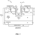
- the field effect device is a silicon carbide (SiC) metal oxide field effect transistor (MOSFET) that has a body 12, which includes a substrate 14, a drift region 16 over the substrate 14, and a channel region 18 over the drift region 16.
- a trench 20 extends into the body 12 from a top surface of the body 12. As illustrated, the trench 20 may extend through the channel region 18 and into the drift region 16 to a depth d T . As such, the trench 20 divides the channel region 18. Source regions 22 are effectively formed in the channel regions 18 on either side of the trench 20.
- the substrate 14 may be an N-doped, single crystal, SiC substrate 14.
- the substrate 14 may have various crystalline polytypes, such as 2H, 4H, 6H, 3C and the like.
- the substrate 14 may also be formed from other material systems, such as gallium nitride (GaN), gallium arsenide (GaAs), silicon (Si), germanium (Ge), SiGe, and the like.
- the substrate may be heavily doped with an N-type dopant at concentrations of between about 1x10 17 cm -3 and 1x10 19 cm -3 and have a thickness of between about 100 microns and 600 microns; however, the doping concentrations and thicknesses of the substrate 14 and the other layers may vary based on the desired parameters of the field effect device 10.
- a SiC drift region 16 may be grown over the substrate 14 and doped in situ, wherein the drift region 16 is lightly doped as it is grown with an N-type doping material.
- one or more buffer layers may be formed on the substrate 14 prior to forming the drift region 16.
- the buffer layer(s) may be used as a nucleation layer and be relatively heavily doped with an N-type doping material.
- the drift region 16 may be relatively uniformly doped throughout or may employ graded doping throughout all or a portion thereof.
- the doping concentration may be between about 1x10 14 cm -3 and 1x10 16 cm -3 in one example useful for understanding the present invention. With graded doping, the doping concentration is highest at the bottom of the drift region 16 near the substrate 14 and lowest at the top of the drift region 16. The doping concentration generally decreases in a stepwise or continuous fashion from a point at or near the bottom to a point at or near the top of the drift region 16.
- the lower portion of the drift region16 may be doped at a concentration of about 1x10 14 cm -3 and the upper portion of the drift region 16 may be doped at a concentration of about 1x10 16 cm -3 .
- the drift region 16 may be between four and ten microns thick depending on the desired parameters of the field effect device 10.
- a SiC channel region 18 may be grown over the drift region 16 and doped in situ, wherein the channel region 18 is heavily doped as it is grown with a P-type doping material at concentrations between about 1x10 17 cm -3 and 5x10 18 cm -3 .
- the channel region 18 at its thickest point may be between about 1 microns and 5 microns.
- the source regions 22 Prior to the trench 20 being formed, the source regions 22 are effectively created as a single source well in the channel region 18 and heavily doped with an N-type doping material.
- the trench 20 is etched from the top surface of the body 12 through the central portion of the source well and the channel region 18 and into the drift region 16. As a result, a channel region 18 and a source region 22 are provided on each side of the trench 20. Both side walls of the trench 20 are formed from portions of the source region 22, the channel regions 18, and the drift region 16. The bottom of the trench 20 resides in the drift region 16 and extends between the lower ends of the side walls of the trench 20.
- the side walls of the trench 20 are substantially orthogonal to the top surface of the body 12, and the bottom of the trench 20 is substantially parallel to the top surface of the body 12.
- the corners between the bottom and the side walls of the trench 20 are rounded to reduce electric field concentrations, which would be higher with sharper corners.
- the gate assembly for the field effect device 10 is formed in the trench 20 and includes a uniquely formed dielectric layer 24 and a gate contact 26.
- the dielectric layer 24 is formed substantially continuously along the side walls and bottom of the trench 20.
- the gate contact 26 is formed on the dielectric layer 24.
- the dielectric layer 24 may be an oxide, such as silicon dioxide (SiO 2 ), aluminum oxide (AlO 2 ), magnesium oxide (MgO).
- the dielectric layer 24 may be formed from multiple layers of dielectric oxides, nitrides, or both as well as mixed alloys of similar dielectrics.
- the dielectric layer 24 is an oxide.
- the gate contact 26 is generally relatively thick and formed from a highly doped semiconductor such as Si or Ge, or a metal, such as aluminum (Al), gold (Au), Silver (Ag), and the like.
- the bottom thickness T B of the dielectric layer 24 on the bottom of the trench 20 is greater than the side thickness T S of the dielectric layer 24 on the side walls of the trench 20.
- the thickness of the dielectric layer 24 on the bottom surface may exceed that of the side walls by 25% or more, 50% or more, or even 100% or more.
- the bottom of the trench 20 is approximately 100%, or two times, greater than the side thickness T S of the dielectric layer 24 on the side walls of the trench 20.
- the dielectric layer is grown using a thermal growth process.
- the thermal growth process where the trench is etched into the Si-face (0001) SiC, the growth rate of the oxide on the bottom (Si-face (0001)) of the trench is around three times slower than that on the side walls, which may reside in the a-face ⁇ 11-20 ⁇ and m-face ⁇ 10-10 ⁇ family of planes.
- the thickness of the dielectric layer on the side walls is much thicker than the dielectric layer on the bottom of the trench.
- the thicker dielectric layer on the side walls leads to higher electric fields along the portion of the dielectric layer that is formed on the bottom of the trench than along the portions of the dielectric layer that are formed on the side walls of the trench.
- the higher electric fields along the portion of the dielectric layer along the bottom of the trench leads to device failure, and thus, reduces the long-term reliability of the field effect device.
- an example useful for understanding the present invention provides for the bottom thickness T B of the dielectric layer 24 on the bottom of the trench 20 to be greater than the side thickness Ts of the dielectric layer 24 on the side walls of the trench 20.
- the bottom thickness T B of the dielectric layer 24 on the bottom of the trench 20 is substantially greater than the side thickness Ts of the dielectric layer 24 on the side walls of the trench 20.
- the MOSFET example useful for understanding the present invention of the field effect device 10 includes source contacts 28 on the respective source regions 22 and one or more drain contacts 30 on the bottom surface of the substrate 14.
- the source and drain contacts 28, 30 may be formed from aluminum (Al), gold (Au), Silver (Ag), and the like.
- the width of the trench 20 and the thicknesses of the dielectric layer 24 and the metal for the gate contact 26 on the side walls is such that the gate contact 26 is U-shaped.
- an open trench is formed by the gate contact 26.
- Other materials may fill the open trench during subsequent processing steps.
- Figure 2 shows the metal for the gate contact 26 completely, or at least substantially, fills any trench left over after the dielectric layer 24 has been deposited on the bottom and side walls of the trench 20.
- Figure 2 illustrates the bottom thickness T B of the dielectric layer 24 on the bottom of the trench 20 is approximately equal to the side thickness T S of the dielectric layer 24 on the side walls of the trench 20.
- the side walls of the trench 20 form an angle ⁇ of less than 90° with the top surface, such that the trench is generally V-shaped. As such, the side walls of the trench 20 do not need to be orthogonal to the top surface of the body 12.
- the bottom thickness T B of the dielectric layer 24 on the bottom of the trench 20 is approximately 100%, or two times, greater than the side thickness T S of the dielectric layer 24 on the side walls of the trench 20.
- the bottom thickness T B of the dielectric layer 24 on the bottom of the trench 20 may be between 80 and 100 nanometers (nm) while the side thickness T S of the dielectric layer 24 on the side walls of the trench 20 may be between 40 and 50 nm.
- the bottom thickness T B may range between 20 and 200 nm or more, and the side thickness T S may range between 10 and 50 nm, 5 and 100 nm, and 25 and 75 nm, depending on the desired performance parameters.
- an exemplary process is provided for forming the dielectric layer 24 such that the bottom thickness T B of the dielectric layer 24 on the bottom of the trench 20 is greater than the side thickness T S of the dielectric layer 24 on the side walls of the trench 20.
- the process is performed on a field effect device precursor that includes the body 12 without the trench 20 being etched.
- the trench 20 is formed into the top surface of the body 12 wherein the top surface corresponds to the Si-face (0001) SiC (step 100).
- the trench 20 may be formed using standard etching processes, or perhaps a mechanical cutting process.
- the trench 20 will pass through the source regions 22 and the channel regions 18 into the drift region 16.
- the dielectric layer is deposited using a deposition process until the bottom thickness T B of the dielectric layer 24 on the bottom of the trench 20 and the side thickness T S of the dielectric layer 24 on the side walls of the trench 20 reach desired levels (step 102).
- the bottom thickness T B of the dielectric layer 24 on the bottom of the trench 20 and the side thickness T S of the dielectric layer 24 on the side walls of the trench 20 are more readily controlled.
- a deposition process allows the dielectric layer 24 to form such that the bottom thickness T B of the dielectric layer 24 on the bottom of the trench 20 is greater than the side thickness T S of the dielectric layer 24 on the side walls of the trench 20.
- the dielectric layer 24 may be silicon dioxide (SiO 2 ), aluminum oxide (AlO 2 ), magnesium oxide (MgO); according to an example useful for understanding the present invention, it may be formed from multiple layers of dielectric oxides or nitrides, from mixed alloys of similar dielectrics, or the like.
- a silicon dioxide (SiO 2 ) dielectric layer 24 is an effective match with SiC-based applications.
- the dielectric layer 24 may be annealed in an oxidant, such as oxygen (O 2 ), nitrous oxide (N 2 O), water, or the like (step 104).
- the annealing may take place at a relatively high temperature, such as between 1100 and 1300 Celsius (C) and last for 0.1 to 10 hours. This annealing step is optional in this exemplary process, but may be used to improve the insulating properties of the dielectric layer 24.
- the dielectric layer 24 is annealed in nitric oxide (NO) (step 106).
- This step of annealing in nitric oxide (NO) has been found to increase the density of the dielectric layer 24 and enhance the molecular interface between the dielectric layer 24 and the trench 20.
- Annealing with nitric oxide (NO) allows nitrogen (N) to build up at the interface between the dielectric layer 24 and the trench 20, and thus, provides nitrogen passivation PN (see Figures 1-3 , 5 , and 6 ) at the interface.
- the annealing may take place at a relatively high temperature, such as between 1100 and 1300 Celsius (C) and last for 0.5 to 5 hours.
- the gate contact 26 may be formed over the annealed dielectric layer 24 (step 108).
- the gate contact 26 may be formed in conjunction with forming the source contacts 28.
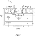
- the field effect device 10' is a SiC insulated gate bipolar transistor (IGBT), which has a body 32 that is configured similarly to the MOSFET described above.
- the gate assembly is formed in the same manner as that described above.
- the body 32 of the IGBT includes a substrate 34, a drift region 36 over the substrate 34, and a channel region 38 over the drift region 36.
- a trench 40 extends into the body 32 from a top surface of the body 32. As described above, the trench 40 may extend through the channel region 38 and into the drift region 36 to a depth d T . As such, the trench 40 divides the channel region 38. Emitter regions 42 are effectively formed in the channel regions 38 on either side of the trench 40.
- the substrate 34 may be a P-doped, single crystal, SiC substrate 34.
- the substrate 34 may be heavily doped with a P-type dopant at concentrations of between about 1x10 16 cm -3 and 1x10 19 cm -3 and have a thickness of between about 2 microns and 500 microns; however, the doping concentrations and thicknesses of the substrate 34 and the other layers may vary based on the desired parameters of the IGBT variant of the field effect device 10'.
- a SiC drift region 36 may be grown over the substrate 34 and doped in situ, wherein the drift region 36 is lightly doped as it is grown with an N-type doping material.
- one or more buffer layers may be formed on the substrate 34 prior to forming the drift region 36.
- the buffer layer(s) may be used as a nucleation layer and be relatively heavily doped with an N-type doping material.
- the drift region 36 may be relatively uniformly doped throughout or may employ graded doping throughout all or a portion thereof.
- the doping concentration may be between about 1x10 14 cm -3 and 1x10 16 cm -3 .
- graded doping the doping concentration is highest at the bottom of the drift region 36 near the substrate 34 and lowest at the top of the drift region 36.
- the doping concentration generally decreases in a stepwise or continuous fashion from a point at or near the bottom to a point at or near the top of the drift region 36.
- a SiC channel region 38 may be grown over the drift region 36 and doped in situ, wherein the channel region 38 is heavily doped as it is grown with a P-type doping material at concentrations between about 1x10 17 cm -3 and 5x10 18 cm -3 .
- the emitter regions 42 Prior to a trench 40 being formed, the emitter regions 42 are effectively created as a single emitter well in the channel region 38 and heavily doped with an N-type doping material.
- the trench 40 is etched from the top surface of the body 32 through the central portion of the emitter well and the channel region 38 and into the drift region 36. As a result, a channel region 38 and an emitter region 42 are provided on each side of the trench 40. Both side walls of the trench 40 are formed from portions of the emitter region 42, the channel regions 38, and the drift region 36.
- One or more collector contacts 50 are provided on the bottom surface of the substrate 34.
- the bottom of the trench 40 resides in the drift region 36 and extends between the lower ends of the side walls of the trench 40.
- the side walls of the trench 40 are substantially orthogonal to the top surface of the body 32, and the bottom of the trench 40 is substantially parallel to the top surface of the body 32.
- the corners between the bottom and the side walls of the trench 40 are rounded to reduce electric field concentrations, which would be higher with sharper corners.
- the gate assembly for the IGBT is formed in the trench 40 and includes a uniquely formed dielectric layer 44 and a gate contact 46.
- the dielectric layer 44 is formed substantially continuously along the side walls and bottom of the trench 40.
- the gate contact 46 is formed on the dielectric layer 44.
- the bottom thickness T B of the dielectric layer 44 on the bottom of the trench 40 is greater than the side thickness T S of the dielectric layer 24 on the side walls of the trench 40.
- Figure 6 shows the metal for the gate contact 46 completely, or at least substantially, fills any trench left over after the dielectric layer 44 has been deposited on the bottom and side walls of the trench 40.
- Figure 6 illustrates the bottom thickness T B of the dielectric layer 44 on the bottom of the trench 40 is approximately equal to the side thickness T S of the dielectric layer 44 on the side walls of the trench 40.
- the trench 40 may be created such that the side walls of the trench 40 form an angle ⁇ of less than 90° with the top surface, such that the trench is generally V-shaped.
Landscapes
- Engineering & Computer Science (AREA)
- Chemical & Material Sciences (AREA)
- Crystallography & Structural Chemistry (AREA)
- Physics & Mathematics (AREA)
- Condensed Matter Physics & Semiconductors (AREA)
- General Physics & Mathematics (AREA)
- Manufacturing & Machinery (AREA)
- Computer Hardware Design (AREA)
- Microelectronics & Electronic Packaging (AREA)
- Power Engineering (AREA)
- Electrodes Of Semiconductors (AREA)
- Insulated Gate Type Field-Effect Transistor (AREA)
Priority Applications (1)
| Application Number | Priority Date | Filing Date | Title |
|---|---|---|---|
| EP20213192.6A EP3826073A1 (en) | 2013-07-17 | 2014-07-14 | Enhanced gate dielectric for a field effect device with a trenched gate |
Applications Claiming Priority (2)
| Application Number | Priority Date | Filing Date | Title |
|---|---|---|---|
| US13/944,473 US9570570B2 (en) | 2013-07-17 | 2013-07-17 | Enhanced gate dielectric for a field effect device with a trenched gate |
| PCT/US2014/046505 WO2015050615A2 (en) | 2013-07-17 | 2014-07-14 | Enhanced gate dielectric for a field effect device with a trenched gate |
Related Child Applications (2)
| Application Number | Title | Priority Date | Filing Date |
|---|---|---|---|
| EP20213192.6A Division EP3826073A1 (en) | 2013-07-17 | 2014-07-14 | Enhanced gate dielectric for a field effect device with a trenched gate |
| EP20213192.6A Division-Into EP3826073A1 (en) | 2013-07-17 | 2014-07-14 | Enhanced gate dielectric for a field effect device with a trenched gate |
Publications (2)
| Publication Number | Publication Date |
|---|---|
| EP3022772A2 EP3022772A2 (en) | 2016-05-25 |
| EP3022772B1 true EP3022772B1 (en) | 2021-02-17 |
Family
ID=52342857
Family Applications (2)
| Application Number | Title | Priority Date | Filing Date |
|---|---|---|---|
| EP14830427.2A Active EP3022772B1 (en) | 2013-07-17 | 2014-07-14 | Enhanced gate dielectric for a field effect device with a trenched gate |
| EP20213192.6A Pending EP3826073A1 (en) | 2013-07-17 | 2014-07-14 | Enhanced gate dielectric for a field effect device with a trenched gate |
Family Applications After (1)
| Application Number | Title | Priority Date | Filing Date |
|---|---|---|---|
| EP20213192.6A Pending EP3826073A1 (en) | 2013-07-17 | 2014-07-14 | Enhanced gate dielectric for a field effect device with a trenched gate |
Country Status (4)
| Country | Link |
|---|---|
| US (1) | US9570570B2 (enExample) |
| EP (2) | EP3022772B1 (enExample) |
| JP (1) | JP2016528729A (enExample) |
| WO (1) | WO2015050615A2 (enExample) |
Families Citing this family (7)
| Publication number | Priority date | Publication date | Assignee | Title |
|---|---|---|---|---|
| JP2016164906A (ja) * | 2015-03-06 | 2016-09-08 | 豊田合成株式会社 | 半導体装置およびその製造方法ならびに電力変換装置 |
| US9991379B1 (en) | 2016-11-17 | 2018-06-05 | Sanken Electric Co., Ltd. | Semiconductor device with a gate insulating film formed on an inner wall of a trench, and method of manufacturing the same |
| DE102016015475B3 (de) * | 2016-12-28 | 2018-01-11 | 3-5 Power Electronics GmbH | IGBT Halbleiterstruktur |
| US11355630B2 (en) | 2020-09-11 | 2022-06-07 | Wolfspeed, Inc. | Trench bottom shielding methods and approaches for trenched semiconductor device structures |
| US11640990B2 (en) | 2020-10-27 | 2023-05-02 | Wolfspeed, Inc. | Power semiconductor devices including a trenched gate and methods of forming such devices |
| JP7697286B2 (ja) * | 2021-06-21 | 2025-06-24 | 富士電機株式会社 | 炭化珪素半導体装置および炭化珪素半導体装置の製造方法 |
| JP7697313B2 (ja) * | 2021-08-17 | 2025-06-24 | 富士電機株式会社 | 炭化珪素半導体装置および炭化珪素半導体装置の製造方法 |
Citations (2)
| Publication number | Priority date | Publication date | Assignee | Title |
|---|---|---|---|---|
| JP2008311406A (ja) * | 2007-06-14 | 2008-12-25 | Toyota Motor Corp | 溝ゲート型SiC半導体装置の製造方法 |
| US20110017998A1 (en) * | 2009-07-21 | 2011-01-27 | Rohm Co., Ltd. | Semiconductor device |
Family Cites Families (20)
| Publication number | Priority date | Publication date | Assignee | Title |
|---|---|---|---|---|
| JP3123061B2 (ja) * | 1990-06-13 | 2001-01-09 | ソニー株式会社 | バイアスecr―cvd法による埋め込み平坦化方法 |
| US5382541A (en) * | 1992-08-26 | 1995-01-17 | Harris Corporation | Method for forming recessed oxide isolation containing deep and shallow trenches |
| US6573534B1 (en) * | 1995-09-06 | 2003-06-03 | Denso Corporation | Silicon carbide semiconductor device |
| JP3419163B2 (ja) * | 1995-09-06 | 2003-06-23 | 株式会社デンソー | 炭化珪素半導体装置の製造方法 |
| JP5116910B2 (ja) * | 1999-02-23 | 2013-01-09 | パナソニック株式会社 | 絶縁ゲート型半導体素子の製造方法 |
| US6291298B1 (en) * | 1999-05-25 | 2001-09-18 | Advanced Analogic Technologies, Inc. | Process of manufacturing Trench gate semiconductor device having gate oxide layer with multiple thicknesses |
| US6696726B1 (en) * | 2000-08-16 | 2004-02-24 | Fairchild Semiconductor Corporation | Vertical MOSFET with ultra-low resistance and low gate charge |
| US7074643B2 (en) | 2003-04-24 | 2006-07-11 | Cree, Inc. | Silicon carbide power devices with self-aligned source and well regions and methods of fabricating same |
| GB0312512D0 (en) * | 2003-05-31 | 2003-07-09 | Koninkl Philips Electronics Nv | Termination structures for semiconductor devices and the manufacture thereof |
| JP5017823B2 (ja) * | 2005-09-12 | 2012-09-05 | 富士電機株式会社 | 半導体素子の製造方法 |
| WO2007086196A1 (ja) | 2006-01-30 | 2007-08-02 | Sumitomo Electric Industries, Ltd. | 炭化珪素半導体装置の製造方法 |
| JP2008011406A (ja) | 2006-06-30 | 2008-01-17 | Toshiba Corp | 受信装置および送信装置 |
| US20090142899A1 (en) * | 2007-12-04 | 2009-06-04 | Jensen Jacob M | Interfacial layer for hafnium-based high-k/metal gate transistors |
| DE112010001476B4 (de) * | 2009-03-11 | 2017-11-30 | Mitsubishi Electric Corporation | Verfahren zur Herstellung eines Siliciumcarbidhalbleiterbauteils |
| CN102804349B (zh) | 2010-03-12 | 2015-07-29 | 住友电气工业株式会社 | 碳化硅半导体器件及其制造方法 |
| JP2012209422A (ja) * | 2011-03-30 | 2012-10-25 | Sumitomo Electric Ind Ltd | Igbt |
| JP6037499B2 (ja) * | 2011-06-08 | 2016-12-07 | ローム株式会社 | 半導体装置およびその製造方法 |
| JP5751113B2 (ja) * | 2011-09-28 | 2015-07-22 | 住友電気工業株式会社 | 炭化珪素半導体装置の製造方法 |
| JP5834801B2 (ja) | 2011-11-16 | 2015-12-24 | 住友電気工業株式会社 | 半導体装置の製造方法および半導体装置 |
| JP5763514B2 (ja) * | 2011-12-13 | 2015-08-12 | トヨタ自動車株式会社 | スイッチング素子の製造方法 |
-
2013
- 2013-07-17 US US13/944,473 patent/US9570570B2/en active Active
-
2014
- 2014-07-14 EP EP14830427.2A patent/EP3022772B1/en active Active
- 2014-07-14 JP JP2016527010A patent/JP2016528729A/ja active Pending
- 2014-07-14 EP EP20213192.6A patent/EP3826073A1/en active Pending
- 2014-07-14 WO PCT/US2014/046505 patent/WO2015050615A2/en not_active Ceased
Patent Citations (2)
| Publication number | Priority date | Publication date | Assignee | Title |
|---|---|---|---|---|
| JP2008311406A (ja) * | 2007-06-14 | 2008-12-25 | Toyota Motor Corp | 溝ゲート型SiC半導体装置の製造方法 |
| US20110017998A1 (en) * | 2009-07-21 | 2011-01-27 | Rohm Co., Ltd. | Semiconductor device |
Also Published As
| Publication number | Publication date |
|---|---|
| EP3022772A2 (en) | 2016-05-25 |
| JP2016528729A (ja) | 2016-09-15 |
| EP3826073A1 (en) | 2021-05-26 |
| WO2015050615A2 (en) | 2015-04-09 |
| WO2015050615A3 (en) | 2015-05-28 |
| US9570570B2 (en) | 2017-02-14 |
| US20150021623A1 (en) | 2015-01-22 |
Similar Documents
| Publication | Publication Date | Title |
|---|---|---|
| EP3022772B1 (en) | Enhanced gate dielectric for a field effect device with a trenched gate | |
| US9318619B2 (en) | Vertical gallium nitride JFET with gate and source electrodes on regrown gate | |
| US10256294B2 (en) | Vertical gallium nitride power field-effect transistor with a field plate structure | |
| JP5671779B2 (ja) | エピタキシャルウエハの製造方法および半導体装置の製造方法 | |
| US8841741B2 (en) | High breakdown voltage semiconductor rectifier | |
| US9502544B2 (en) | Method and system for planar regrowth in GaN electronic devices | |
| JP2014146666A (ja) | 半導体装置 | |
| US9269781B2 (en) | Semiconductor device and method for manufacturing the same | |
| US10707306B2 (en) | Semiconductor device and method of manufacturing the same | |
| CN110828456B (zh) | 用于在功率器件中减小衬底掺杂剂向外扩散的氧插入的Si层 | |
| US20170077285A1 (en) | Semiconductor device | |
| CN109148573A (zh) | 半导体装置 | |
| US8866148B2 (en) | Vertical GaN power device with breakdown voltage control | |
| JP3664158B2 (ja) | 炭化珪素半導体装置およびその製造方法 | |
| JP4049095B2 (ja) | 半導体装置及びその製造方法 | |
| JP5145694B2 (ja) | SiC半導体縦型MOSFETの製造方法。 | |
| US20190333998A1 (en) | Silicon carbide epitaxial wafer and silicon carbide semiconductor device | |
| JP2020080369A (ja) | 半導体装置とその製造方法 | |
| CN118016700A (zh) | 碳化硅槽栅复合介质mosfet功率器件的制造方法 | |
| KR102829615B1 (ko) | 쇼트키 배리어 다이오드 및 이의 제조 방법 | |
| JP2006245243A (ja) | 半導体装置およびその製造方法 | |
| JP5997746B2 (ja) | 半導体装置 | |
| JP2007088186A (ja) | 半導体装置及びその製造方法 | |
| JP2009070935A (ja) | 窒化物半導体装置 | |
| JP2006128492A (ja) | エピタキシャル基板、および半導体素子 |
Legal Events
| Date | Code | Title | Description |
|---|---|---|---|
| PUAI | Public reference made under article 153(3) epc to a published international application that has entered the european phase |
Free format text: ORIGINAL CODE: 0009012 |
|
| 17P | Request for examination filed |
Effective date: 20160114 |
|
| AK | Designated contracting states |
Kind code of ref document: A2 Designated state(s): AL AT BE BG CH CY CZ DE DK EE ES FI FR GB GR HR HU IE IS IT LI LT LU LV MC MK MT NL NO PL PT RO RS SE SI SK SM TR |
|
| AX | Request for extension of the european patent |
Extension state: BA ME |
|
| DAX | Request for extension of the european patent (deleted) | ||
| STAA | Information on the status of an ep patent application or granted ep patent |
Free format text: STATUS: EXAMINATION IS IN PROGRESS |
|
| 17Q | First examination report despatched |
Effective date: 20181015 |
|
| GRAP | Despatch of communication of intention to grant a patent |
Free format text: ORIGINAL CODE: EPIDOSNIGR1 |
|
| STAA | Information on the status of an ep patent application or granted ep patent |
Free format text: STATUS: GRANT OF PATENT IS INTENDED |
|
| RIC1 | Information provided on ipc code assigned before grant |
Ipc: H01L 29/78 20060101AFI20200908BHEP Ipc: H01L 21/336 20060101ALI20200908BHEP Ipc: H01L 21/12 20060101ALI20200908BHEP Ipc: H01L 29/423 20060101ALI20200908BHEP Ipc: H01L 29/16 20060101ALN20200908BHEP |
|
| INTG | Intention to grant announced |
Effective date: 20200924 |
|
| GRAS | Grant fee paid |
Free format text: ORIGINAL CODE: EPIDOSNIGR3 |
|
| GRAA | (expected) grant |
Free format text: ORIGINAL CODE: 0009210 |
|
| STAA | Information on the status of an ep patent application or granted ep patent |
Free format text: STATUS: THE PATENT HAS BEEN GRANTED |
|
| AK | Designated contracting states |
Kind code of ref document: B1 Designated state(s): AL AT BE BG CH CY CZ DE DK EE ES FI FR GB GR HR HU IE IS IT LI LT LU LV MC MK MT NL NO PL PT RO RS SE SI SK SM TR |
|
| REG | Reference to a national code |
Ref country code: GB Ref legal event code: FG4D |
|
| REG | Reference to a national code |
Ref country code: CH Ref legal event code: EP |
|
| REG | Reference to a national code |
Ref country code: DE Ref legal event code: R096 Ref document number: 602014074934 Country of ref document: DE |
|
| REG | Reference to a national code |
Ref country code: AT Ref legal event code: REF Ref document number: 1362610 Country of ref document: AT Kind code of ref document: T Effective date: 20210315 |
|
| REG | Reference to a national code |
Ref country code: IE Ref legal event code: FG4D |
|
| REG | Reference to a national code |
Ref country code: LT Ref legal event code: MG9D |
|
| REG | Reference to a national code |
Ref country code: NL Ref legal event code: MP Effective date: 20210217 |
|
| PG25 | Lapsed in a contracting state [announced via postgrant information from national office to epo] |
Ref country code: PT Free format text: LAPSE BECAUSE OF FAILURE TO SUBMIT A TRANSLATION OF THE DESCRIPTION OR TO PAY THE FEE WITHIN THE PRESCRIBED TIME-LIMIT Effective date: 20210617 Ref country code: LT Free format text: LAPSE BECAUSE OF FAILURE TO SUBMIT A TRANSLATION OF THE DESCRIPTION OR TO PAY THE FEE WITHIN THE PRESCRIBED TIME-LIMIT Effective date: 20210217 Ref country code: FI Free format text: LAPSE BECAUSE OF FAILURE TO SUBMIT A TRANSLATION OF THE DESCRIPTION OR TO PAY THE FEE WITHIN THE PRESCRIBED TIME-LIMIT Effective date: 20210217 Ref country code: GR Free format text: LAPSE BECAUSE OF FAILURE TO SUBMIT A TRANSLATION OF THE DESCRIPTION OR TO PAY THE FEE WITHIN THE PRESCRIBED TIME-LIMIT Effective date: 20210518 Ref country code: HR Free format text: LAPSE BECAUSE OF FAILURE TO SUBMIT A TRANSLATION OF THE DESCRIPTION OR TO PAY THE FEE WITHIN THE PRESCRIBED TIME-LIMIT Effective date: 20210217 Ref country code: BG Free format text: LAPSE BECAUSE OF FAILURE TO SUBMIT A TRANSLATION OF THE DESCRIPTION OR TO PAY THE FEE WITHIN THE PRESCRIBED TIME-LIMIT Effective date: 20210517 Ref country code: NO Free format text: LAPSE BECAUSE OF FAILURE TO SUBMIT A TRANSLATION OF THE DESCRIPTION OR TO PAY THE FEE WITHIN THE PRESCRIBED TIME-LIMIT Effective date: 20210517 |
|
| PG25 | Lapsed in a contracting state [announced via postgrant information from national office to epo] |
Ref country code: SE Free format text: LAPSE BECAUSE OF FAILURE TO SUBMIT A TRANSLATION OF THE DESCRIPTION OR TO PAY THE FEE WITHIN THE PRESCRIBED TIME-LIMIT Effective date: 20210217 Ref country code: LV Free format text: LAPSE BECAUSE OF FAILURE TO SUBMIT A TRANSLATION OF THE DESCRIPTION OR TO PAY THE FEE WITHIN THE PRESCRIBED TIME-LIMIT Effective date: 20210217 Ref country code: PL Free format text: LAPSE BECAUSE OF FAILURE TO SUBMIT A TRANSLATION OF THE DESCRIPTION OR TO PAY THE FEE WITHIN THE PRESCRIBED TIME-LIMIT Effective date: 20210217 Ref country code: RS Free format text: LAPSE BECAUSE OF FAILURE TO SUBMIT A TRANSLATION OF THE DESCRIPTION OR TO PAY THE FEE WITHIN THE PRESCRIBED TIME-LIMIT Effective date: 20210217 Ref country code: NL Free format text: LAPSE BECAUSE OF FAILURE TO SUBMIT A TRANSLATION OF THE DESCRIPTION OR TO PAY THE FEE WITHIN THE PRESCRIBED TIME-LIMIT Effective date: 20210217 |
|
| PG25 | Lapsed in a contracting state [announced via postgrant information from national office to epo] |
Ref country code: IS Free format text: LAPSE BECAUSE OF FAILURE TO SUBMIT A TRANSLATION OF THE DESCRIPTION OR TO PAY THE FEE WITHIN THE PRESCRIBED TIME-LIMIT Effective date: 20210617 |
|
| PG25 | Lapsed in a contracting state [announced via postgrant information from national office to epo] |
Ref country code: SM Free format text: LAPSE BECAUSE OF FAILURE TO SUBMIT A TRANSLATION OF THE DESCRIPTION OR TO PAY THE FEE WITHIN THE PRESCRIBED TIME-LIMIT Effective date: 20210217 Ref country code: CZ Free format text: LAPSE BECAUSE OF FAILURE TO SUBMIT A TRANSLATION OF THE DESCRIPTION OR TO PAY THE FEE WITHIN THE PRESCRIBED TIME-LIMIT Effective date: 20210217 Ref country code: EE Free format text: LAPSE BECAUSE OF FAILURE TO SUBMIT A TRANSLATION OF THE DESCRIPTION OR TO PAY THE FEE WITHIN THE PRESCRIBED TIME-LIMIT Effective date: 20210217 |
|
| REG | Reference to a national code |
Ref country code: AT Ref legal event code: UEP Ref document number: 1362610 Country of ref document: AT Kind code of ref document: T Effective date: 20210217 |
|
| REG | Reference to a national code |
Ref country code: DE Ref legal event code: R097 Ref document number: 602014074934 Country of ref document: DE |
|
| PG25 | Lapsed in a contracting state [announced via postgrant information from national office to epo] |
Ref country code: RO Free format text: LAPSE BECAUSE OF FAILURE TO SUBMIT A TRANSLATION OF THE DESCRIPTION OR TO PAY THE FEE WITHIN THE PRESCRIBED TIME-LIMIT Effective date: 20210217 Ref country code: SK Free format text: LAPSE BECAUSE OF FAILURE TO SUBMIT A TRANSLATION OF THE DESCRIPTION OR TO PAY THE FEE WITHIN THE PRESCRIBED TIME-LIMIT Effective date: 20210217 Ref country code: DK Free format text: LAPSE BECAUSE OF FAILURE TO SUBMIT A TRANSLATION OF THE DESCRIPTION OR TO PAY THE FEE WITHIN THE PRESCRIBED TIME-LIMIT Effective date: 20210217 Ref country code: ES Free format text: LAPSE BECAUSE OF FAILURE TO SUBMIT A TRANSLATION OF THE DESCRIPTION OR TO PAY THE FEE WITHIN THE PRESCRIBED TIME-LIMIT Effective date: 20210217 |
|
| PLBE | No opposition filed within time limit |
Free format text: ORIGINAL CODE: 0009261 |
|
| STAA | Information on the status of an ep patent application or granted ep patent |
Free format text: STATUS: NO OPPOSITION FILED WITHIN TIME LIMIT |
|
| 26N | No opposition filed |
Effective date: 20211118 |
|
| PG25 | Lapsed in a contracting state [announced via postgrant information from national office to epo] |
Ref country code: AL Free format text: LAPSE BECAUSE OF FAILURE TO SUBMIT A TRANSLATION OF THE DESCRIPTION OR TO PAY THE FEE WITHIN THE PRESCRIBED TIME-LIMIT Effective date: 20210217 |
|
| PG25 | Lapsed in a contracting state [announced via postgrant information from national office to epo] |
Ref country code: SI Free format text: LAPSE BECAUSE OF FAILURE TO SUBMIT A TRANSLATION OF THE DESCRIPTION OR TO PAY THE FEE WITHIN THE PRESCRIBED TIME-LIMIT Effective date: 20210217 |
|
| REG | Reference to a national code |
Ref country code: CH Ref legal event code: PL |
|
| GBPC | Gb: european patent ceased through non-payment of renewal fee |
Effective date: 20210714 |
|
| PG25 | Lapsed in a contracting state [announced via postgrant information from national office to epo] |
Ref country code: MC Free format text: LAPSE BECAUSE OF FAILURE TO SUBMIT A TRANSLATION OF THE DESCRIPTION OR TO PAY THE FEE WITHIN THE PRESCRIBED TIME-LIMIT Effective date: 20210217 |
|
| REG | Reference to a national code |
Ref country code: BE Ref legal event code: MM Effective date: 20210731 |
|
| PG25 | Lapsed in a contracting state [announced via postgrant information from national office to epo] |
Ref country code: LI Free format text: LAPSE BECAUSE OF NON-PAYMENT OF DUE FEES Effective date: 20210731 Ref country code: GB Free format text: LAPSE BECAUSE OF NON-PAYMENT OF DUE FEES Effective date: 20210714 Ref country code: CH Free format text: LAPSE BECAUSE OF NON-PAYMENT OF DUE FEES Effective date: 20210731 |
|
| PG25 | Lapsed in a contracting state [announced via postgrant information from national office to epo] |
Ref country code: IS Free format text: LAPSE BECAUSE OF FAILURE TO SUBMIT A TRANSLATION OF THE DESCRIPTION OR TO PAY THE FEE WITHIN THE PRESCRIBED TIME-LIMIT Effective date: 20210617 Ref country code: LU Free format text: LAPSE BECAUSE OF NON-PAYMENT OF DUE FEES Effective date: 20210714 Ref country code: FR Free format text: LAPSE BECAUSE OF NON-PAYMENT OF DUE FEES Effective date: 20210731 |
|
| PG25 | Lapsed in a contracting state [announced via postgrant information from national office to epo] |
Ref country code: IE Free format text: LAPSE BECAUSE OF NON-PAYMENT OF DUE FEES Effective date: 20210714 Ref country code: BE Free format text: LAPSE BECAUSE OF NON-PAYMENT OF DUE FEES Effective date: 20210731 |
|
| PG25 | Lapsed in a contracting state [announced via postgrant information from national office to epo] |
Ref country code: HU Free format text: LAPSE BECAUSE OF FAILURE TO SUBMIT A TRANSLATION OF THE DESCRIPTION OR TO PAY THE FEE WITHIN THE PRESCRIBED TIME-LIMIT; INVALID AB INITIO Effective date: 20140714 |
|
| PG25 | Lapsed in a contracting state [announced via postgrant information from national office to epo] |
Ref country code: CY Free format text: LAPSE BECAUSE OF FAILURE TO SUBMIT A TRANSLATION OF THE DESCRIPTION OR TO PAY THE FEE WITHIN THE PRESCRIBED TIME-LIMIT Effective date: 20210217 |
|
| PG25 | Lapsed in a contracting state [announced via postgrant information from national office to epo] |
Ref country code: MK Free format text: LAPSE BECAUSE OF FAILURE TO SUBMIT A TRANSLATION OF THE DESCRIPTION OR TO PAY THE FEE WITHIN THE PRESCRIBED TIME-LIMIT Effective date: 20210217 |
|
| PG25 | Lapsed in a contracting state [announced via postgrant information from national office to epo] |
Ref country code: TR Free format text: LAPSE BECAUSE OF FAILURE TO SUBMIT A TRANSLATION OF THE DESCRIPTION OR TO PAY THE FEE WITHIN THE PRESCRIBED TIME-LIMIT Effective date: 20210217 |
|
| PG25 | Lapsed in a contracting state [announced via postgrant information from national office to epo] |
Ref country code: MT Free format text: LAPSE BECAUSE OF FAILURE TO SUBMIT A TRANSLATION OF THE DESCRIPTION OR TO PAY THE FEE WITHIN THE PRESCRIBED TIME-LIMIT Effective date: 20210217 |
|
| REG | Reference to a national code |
Ref country code: DE Ref legal event code: R079 Ref document number: 602014074934 Country of ref document: DE Free format text: PREVIOUS MAIN CLASS: H01L0029780000 Ipc: H10D0030600000 |
|
| PGFP | Annual fee paid to national office [announced via postgrant information from national office to epo] |
Ref country code: DE Payment date: 20250729 Year of fee payment: 12 |
|
| PGFP | Annual fee paid to national office [announced via postgrant information from national office to epo] |
Ref country code: IT Payment date: 20250721 Year of fee payment: 12 |
|
| PGFP | Annual fee paid to national office [announced via postgrant information from national office to epo] |
Ref country code: AT Payment date: 20250620 Year of fee payment: 12 |