EP3021175B1 - Split-seconds device with epicycloidal train for a timepiece - Google Patents
Split-seconds device with epicycloidal train for a timepiece Download PDFInfo
- Publication number
- EP3021175B1 EP3021175B1 EP15187312.2A EP15187312A EP3021175B1 EP 3021175 B1 EP3021175 B1 EP 3021175B1 EP 15187312 A EP15187312 A EP 15187312A EP 3021175 B1 EP3021175 B1 EP 3021175B1
- Authority
- EP
- European Patent Office
- Prior art keywords
- wheel
- split
- chronograph
- hand
- seconds
- Prior art date
- Legal status (The legal status is an assumption and is not a legal conclusion. Google has not performed a legal analysis and makes no representation as to the accuracy of the status listed.)
- Active
Links
- 230000007246 mechanism Effects 0.000 claims description 38
- 238000005259 measurement Methods 0.000 claims description 4
- 230000006870 function Effects 0.000 description 10
- 230000000903 blocking effect Effects 0.000 description 3
- 230000009931 harmful effect Effects 0.000 description 3
- 230000010354 integration Effects 0.000 description 3
- 230000001360 synchronised effect Effects 0.000 description 2
- 241001080024 Telles Species 0.000 description 1
- 238000010719 annulation reaction Methods 0.000 description 1
- 230000001419 dependent effect Effects 0.000 description 1
- 230000001627 detrimental effect Effects 0.000 description 1
- 230000000694 effects Effects 0.000 description 1
- 239000012212 insulator Substances 0.000 description 1
- 238000004519 manufacturing process Methods 0.000 description 1
- 238000012986 modification Methods 0.000 description 1
- 230000004048 modification Effects 0.000 description 1
- 230000000750 progressive effect Effects 0.000 description 1
Images


Classifications
-
- G—PHYSICS
- G04—HOROLOGY
- G04B—MECHANICALLY-DRIVEN CLOCKS OR WATCHES; MECHANICAL PARTS OF CLOCKS OR WATCHES IN GENERAL; TIME PIECES USING THE POSITION OF THE SUN, MOON OR STARS
- G04B19/00—Indicating the time by visual means
- G04B19/04—Hands; Discs with a single mark or the like
-
- G—PHYSICS
- G04—HOROLOGY
- G04F—TIME-INTERVAL MEASURING
- G04F7/00—Apparatus for measuring unknown time intervals by non-electric means
- G04F7/04—Apparatus for measuring unknown time intervals by non-electric means using a mechanical oscillator
- G04F7/08—Watches or clocks with stop devices, e.g. chronograph
- G04F7/0866—Special arrangements
- G04F7/0871—Special arrangements with multiple chronograph functions, i.e. to count multiple running times
-
- G—PHYSICS
- G04—HOROLOGY
- G04B—MECHANICALLY-DRIVEN CLOCKS OR WATCHES; MECHANICAL PARTS OF CLOCKS OR WATCHES IN GENERAL; TIME PIECES USING THE POSITION OF THE SUN, MOON OR STARS
- G04B13/00—Gearwork
- G04B13/007—Gearwork with differential work
- G04B13/008—Differentials
-
- G—PHYSICS
- G04—HOROLOGY
- G04B—MECHANICALLY-DRIVEN CLOCKS OR WATCHES; MECHANICAL PARTS OF CLOCKS OR WATCHES IN GENERAL; TIME PIECES USING THE POSITION OF THE SUN, MOON OR STARS
- G04B13/00—Gearwork
- G04B13/02—Wheels; Pinions; Spindles; Pivots
-
- G—PHYSICS
- G04—HOROLOGY
- G04F—TIME-INTERVAL MEASURING
- G04F3/00—Apparatus which can be set and started to measure-off predetermined or adjustably-fixed time intervals with driving mechanisms, e.g. dosimeters with clockwork
- G04F3/02—Apparatus which can be set and started to measure-off predetermined or adjustably-fixed time intervals with driving mechanisms, e.g. dosimeters with clockwork with mechanical driving mechanisms
- G04F3/025—Apparatus which can be set and started to measure-off predetermined or adjustably-fixed time intervals with driving mechanisms, e.g. dosimeters with clockwork with mechanical driving mechanisms mechanically actuated
-
- G—PHYSICS
- G04—HOROLOGY
- G04F—TIME-INTERVAL MEASURING
- G04F7/00—Apparatus for measuring unknown time intervals by non-electric means
- G04F7/04—Apparatus for measuring unknown time intervals by non-electric means using a mechanical oscillator
- G04F7/08—Watches or clocks with stop devices, e.g. chronograph
- G04F7/0842—Watches or clocks with stop devices, e.g. chronograph with start-stop control mechanisms
-
- G—PHYSICS
- G04—HOROLOGY
- G04F—TIME-INTERVAL MEASURING
- G04F7/00—Apparatus for measuring unknown time intervals by non-electric means
- G04F7/04—Apparatus for measuring unknown time intervals by non-electric means using a mechanical oscillator
- G04F7/08—Watches or clocks with stop devices, e.g. chronograph
- G04F7/0866—Special arrangements
- G04F7/0876—Split-time function, e.g. rattrappante
Definitions
- the subject of the present invention is a split-seconds device for a timepiece, in particular for a chronograph watch, the device comprising a split-seconds pinion carrying a split-second needle and mounted in a freely rotatable manner about an axis of rotation of said cut-off piece. watchmaking.
- a split-seconds device for a timepiece, in particular for a chronograph watch, the device comprising a split-seconds pinion carrying a split-second needle and mounted in a freely rotatable manner about an axis of rotation of said cut-off piece. watchmaking.
- Such a device can be found for example in the document EP 2 239 638 A2 .
- the invention relates to timepieces having a mechanical movement, including mechanical wristwatches.
- This type of timepiece is sometimes equipped with a so-called split-second function.
- one or more needles of the watch have a split second hand in the normal running state of the watch to a corresponding needle.
- the user can, by actuating a split-second pusher, stop the split-second needle, while the corresponding needle continues to rotate, then, by again actuating said split-second pusher, return the split-second needle in superposition with the corresponding needle.
- This function is normally deployed on chronograph watches by equipping at least one or all chronograph hands with a split-second hand, thus allowing, for example, the measurement of intermediate times without stopping the timing of the main timed time.
- this kind of catch-up mechanism requires to equip very thin axes, such as the axes bearing the chronograph hands, hearts on which repeatedly hit the corresponding hammers when the split-second needle should be re-synchronized with the corresponding needle. In the long run, this increases the risk of damage to the mechanism. Moreover, such a catch-up mechanism considerably increases the complexity of the timepiece while adding, for example in the case of an application to a chronograph watch, only as an additional function the measurement of the intermediate times without interrupting the main timing .
- the purpose of the present invention is therefore to overcome, at least partially, the disadvantages of known devices and to make a split-seconds device for timepieces which has a simple and robust structure, in addition to guarantee a cost of reasonable production, as well as reliable operation, and which limits the harmful effects of such a mechanism on the accuracy of operation of the corresponding timepiece.
- the device should optionally be able to enrich the functions offered by such a split mechanism, particularly in the case of its integration into a chronograph watch.
- the present invention proposes a catch-up device of the abovementioned type which is distinguished by the features set forth in claim 1.
- the device according to the present invention comprises a differential comprising an input mobile capable of being kinematically linked. to a power source of the timepiece, a first output mobile kinematically connected to the input mobile by at least one satellite and meshing with the second gear, a second output mobile kinematically linked to said input mobile by said at least one satellite, and a control lever for blocking either the first output mobile or the second output mobile, so that the one between the first output mobile and the second output mobile which is released by the control lever is capable of being driven by said input mobile when the latter is kinematically linked to the source of en ergie of the timepiece, thus making it possible to block respectively release said catch-up needle.
- the device allows to drive or block a split-second needle, for example a chronograph of a mechanical watch, using a planetary system placed between the energy source of the coin d watchmaking and the pinion of the rattrapante needle.
- a differential makes it possible to reduce simultaneously and in a relatively simple manner the difference in the operating accuracy of conventional override mechanisms between their operating state and their off state, limiting the harmful effects of the presence of a split-second needle on the running accuracy of the timepiece equipped with this device.
- the device also comprises a deviation wheel carrying a deviation needle and an intermediate wheel, respectively a boundary wheel carrying a core, the intermediate wheel meshing with said deviation wheel and being kinematically connected to the second mobile Release.
- a deviation wheel carrying a deviation needle and an intermediate wheel respectively a boundary wheel carrying a core
- the intermediate wheel meshing with said deviation wheel and being kinematically connected to the second mobile Release.
- the input mobile of the differential is formed by a sun gear integral with a sun gear
- the first output mobile is formed by a planet carrier carrying at least one satellite meshing with said sun gear
- the second output mobile is formed by an external toothing of a ring meshing via an internal toothing with said at least one satellite.
- the invention also relates to a chronograph mechanism comprising such an epicyclic gear retractor device.
- a chronograph mechanism comprising such an epicyclic gear retractor device.
- the latter is suitable for use in several horological applications, so that it can be used in chronograph watches but also in other types of timepieces.
- the present invention relates to a retraction device with an epicyclic gear train intended to be integrated in a timepiece, preferably in a wristwatch having a mechanical movement, and more particularly in a chronograph watch.
- a timepiece preferably in a wristwatch having a mechanical movement
- chronograph watch a chronograph watch
- an epicyclic gear retractor device can be integrated into modules of such a timepiece, such as a chronograph mechanism or other mechanisms that are likely to be equipped with a device. epicyclic gear retractor according to the present invention.
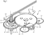
- FIG. 1 illustrate schematically and by way of example a preferred embodiment of such a device in the context of its integration into a chronograph mechanism, respectively in a chronograph watch.
- this retracting device 10 conventionally comprises a split-second pinion 2.1 which carries a split-second needle 2.2 and which is mounted so freely rotatable about an axis of rotation 1 of said timepiece.
- the device is integrated in a chronograph watch, the chronograph mechanism parts being indicated only symbolically by the chronograph wheel 8.1 carrying a chronograph hand 8.2.
- the split-second gear 2.1 and the split-second hand 2.2 are mounted freely rotatably around the axis of rotation 1 of the chronograph wheel 8.1, respectively of the chronograph hand 8.2.
- the chronograph drive train and the other parts of the chronograph mechanism, such as its control, are not illustrated, these parts of the chronograph mechanism being known to those skilled in the art and not requiring a detailed description here.
- the person skilled in the art also knows how the chronograph wheel 8.1 can be connected, following a first actuation of a start-stop chronograph pusher not shown in the figures, to the finishing gear of the timepiece in order to driving the chronograph hand 8.2, then stop it after a second actuation of the chronograph start-stop pusher by disengaging the chronograph wheel of said wheel of the timepiece. Operation of a reset pushbutton then resets the chronograph hand.
- an epicyclic gear split device 10 differs from the devices of the prior art in that it comprises, in general terms, a differential 3 comprising a mobile device.
- input 3.1 capable of being kinematically linked to a power source of the timepiece, a first output mobile 3.2 kinematically connected to the input mobile device 3.1 by at least one satellite 3.4 and meshing with the second-time gear 2.1, and a second output mobile 3.3 kinematically linked to said mobile input 3.1 by said at least one satellite 3.4.
- the device further comprises a control lever 4 making it possible to block either the first output mobile device 3.2 or the second output mobile device 3.3, so that the one between the first output mobile device 3.2 and the second output mobile device 3.3 which is released by the control lever 4 is likely to be driven by said input mobile 3.1 when the latter is kinematically linked to the energy source of the timepiece, thus allowing to block respectively release said split-second needle 2.2.
- the control lever 4 is prestressed by a holding spring not shown in the figures in a first position in which the lever 4 blocks the second output mobile 3.3, so that the split-second hand 2.2 is normally in the released state. .
- the user of the timepiece incorporating a retractor device 10 can return the lever 4 to a second position. in which the lever 4 blocks the first output mobile 3.2, so that the split needle 2.2 is blocked.
- the split-second pusher again, the lever 4 releases the first output mobile 3.2 and returns to its first position in which the lever 4 blocks the second output mobile 3.3.
- the device also comprises a clearance wheel 7.1 kinematically connected to the second output mobile device 3.3 and carrying a shift needle 7.2, as well as an intermediate wheel 6.1 kinematically connected to the second output mobile device 3.3, the intermediate wheel 6.1 meshing with said a gap wheel 7.1.
- a boundary wheel 9.1 is arranged on the periphery of the second output mobile 3.3 so as to mesh with the latter and carries a core 9.2.
- said core could be mounted on the intermediate wheel 6.1 or the clearance wheel 7.1.
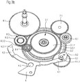
- the figures 1 , 2a , 2b , and 3b show a preferred embodiment of an epicyclic gear retracting device according to the present invention in which the input mobile 3.1 of the differential 3 is formed by a sun gear 3.1.1 integral with a sun gear 3.1.2.
- the first output mobile 3.2 is in this preferred embodiment formed by a planet carrier 3.2 mounted freely rotatable about the axis of the differential 3 and carrying at least one satellite 3.4 meshing with said solar gear 3.1.2.
- On the planet carrier board 3.2 are preferably arranged three satellites 3.4 whose axes have an angular distance equal to each other.
- the second mobile output 3.3 is formed by an external toothing 3.3.1 of a ring gear 3.3 mounted freely rotatably about the axis of the differential 3 and meshing via an internal toothing 3.3.2 with said least one satellite 3.4.
- the external toothing 3.3.1 of said ring gear 3.3 forming the second mobile output 3.3 meshes in this case with said intermediate wheel 6.1 which in turn meshes with the clearance wheel 7.1, thereby achieving particularly simple kinematic connection between the 7.1 deviation wheel and the second exit mobile 3.3.
- the axis of rotation 1 of the chronograph wheel 8.1 and the axis of the differential are mounted on the frame of the timepiece.
- the lever 4 is articulated around a tilting axis 4.3, and said retaining spring exerts a pre-stressing force on a first free end 4.1 of the lever 4 so as to maintain the lever 4 in a first position in which its first end 4.1 blocks the second output mobile 3.3.
- the first end 4.1 and a second free end 4.2 of the lever 4 are each equipped with a support zone 4.1.1, 4.2.1 adapted to cooperate with said core 9.2, respectively with the planet carrier 3.2, and allow press either, via said support zone 4.1.1, on the core 9.2 mounted on the adjacent wheel 9.1 or, via said support zone 4.2.1, on the external toothing of the carrier.
- satellites 3.2 are each equipped with a support zone 4.1.1, 4.2.1 adapted to cooperate with said core 9.2, respectively with the planet carrier 3.2, and allow press either, via said support zone 4.1.1, on the core 9.2 mounted on the adjacent wheel 9.1 or, via said support zone 4.2.1, on the external toothing of the carrier.
- the differential of the retrofit device 10 can be arranged differently without this having a substantial influence on the structure or operation of the device.
- the input mobile 3.1 could act as an output mobile
- the function of the output mobiles 3.2, 3.3 could of course be reversed, by connecting the first output mobile 3.2 via the intermediate wheel 6.1 to the clearance wheel 7.1 and the second output mobile 3.3 to the split wheel 2.1.
- control lever 4 could be replaced by another equivalent control means adapted to cooperate in a similar manner with the split-second pusher.
- the preferred embodiment makes it possible to avoid placing the core 6.2 on a thin axis such as that of the split-second needle.
- the kinematic connection between the chronograph wheel 8.1 and the input mobile 3.1 of the differential 3 is, in the preferred embodiment illustrated in the figures, carried out via a first intermediate gear 8.3 having a first 8.3.1 gear meshing with the chronograph wheel 8.1 and a second gear 8.3.2 meshing with a second intermediate gear 8.4, the latter meshing with the mobile input 3.1. If this solution makes it possible to choose in a particularly easy way the gear ratio between the chronograph wheel 8.1 and the mobile input 3.1, it is nevertheless also possible that the chronograph wheel 8.1 meshes directly with the input mobile 3.
- an epicyclic gear retractor device is preferably equipped with a clearance canceling means arranged between the chronograph wheel and the split wheel, as illustrated in FIG. figure 4 by a schematic top view.
- This game cancellation means comprises a disk-shaped support 5.1 integral with the chronograph wheel 8.1, and therefore of the chronograph hand 8.2, and carrying a jumper 5.2 of substantially circular shape whose angular position about an axis. 5.2.3 can be adjusted.
- the jumper 5.2 forms almost a complete circle, pins 5.3 being placed in the angular sector not occupied by said jumper.
- a first free end 5.2.1 of the jumper 5.2 forms a short arm equipped with a rounded projection 5.2.1.1, while a second free end 5.2.2 of the jumper 5.2 forms a long arm forming an extended arc.
- the clearance canceling means 5 further comprises an eccentric 5.4 of substantially elliptical shape and integral with the split wheel 2.1, and therefore of the split-second needle 2.2.
- the eccentric 5.4 comprises, at the end of its major axis farthest from the center of rotation of the eccentric 5.4, a rounded notch 5.4.1 adapted to cooperate with the rounded projection 5.2.1.1 formed on the first free end 5.2 .1 of the jumper 5.2.
- the rounded projection 5.2.1.1 formed on the first free end 5.2.1 of the jumper 5.2 is in said rounded notch 5.4.1 of the eccentric 5.4, so that the clearance between the needles 2.2, 8.2 is reduced to a minimum.
- the split-second hand 2.2 is stopped, while the chronograph hand 8.2 continues to rotate, so in general during a relative rotation between the needles 2.2, 8.2, the rounded projection 5.2.1.1 formed on the first free end 5.2.1 of the jumper 5.2 comes out of the rounded notch 5.4.1 of the eccentric 5.4.
- the pins 5.3 limit the movement of the free ends 5.2.1, 5.2.2 of the jumper 5.2 to avoid contact with the eccentric 5.4.
- eccentric 5.4 it is possible to replace the eccentric 5.4 by a disc having two teeth cooperating with a jumper of substantially circular shape equipped with a single tooth, and to provide, on the area of said disc not occupied by the two teeth, a radius chosen so as to avoid any friction between the disc and the single tooth of the jumper.
- the adjacent wheel 9.1 and the ring gear 3.3 whose external toothing 3.3.1 meshes with the neighboring wheel 9.1, are locked against rotation, so that the planet carrier 3.2 and the split wheel gear 2.1 meshing with the planet carrier 3.2 and carrying the split-second hand 2.2 are released.
- the chronograph wheel 8.1 when the chronograph wheel 8.1 is engaged with the finishing gear of the timepiece and is therefore in kinematic connection with the energy source of the timepiece, it rotates, by the intermediate first and second intermediate gears 8.3, 8.4, the sun wheel 3.1.1.
- the solar gear 3.1.2 integral with the sun gear 3.1.1 meshes with the satellites 3.4 and thus causes rotation of the planet carrier 3.2, since the ring gear 3.3 is blocked and forces the satellites 3.4 to move along its axis.
- the ring gear 3.3 rotates the boundary wheel 9.1 carrying the core 9.2 and the intermediate wheel 6.1 and thus causes a rotation of the clearance wheel 7.1. Since the numbers of teeth on the intermediate wheel 6.1 and the clearance wheel 7.1 and therefore their gear ratios are also appropriately selected, the shift needle 7.2 mounted on the clearance wheel Synchronous rotation with the chronograph hand 8.2 which is driven directly by the chronograph wheel 8.1. Thus, the offset needle 7.2 makes it possible to display the time difference between the chronograph hand 8.2 and the split-second hand 2.2 when the latter is stopped.
- the control lever 4 When the user of the timepiece actuates the split-back push-button again, the control lever 4 returns to its first position in which the bearing zone 4.1.1 of the first free end 4.1 of this lever 4 bears on the core 9.2, by releasing the planet carrier 3.2, respectively by blocking the ring 3.3.
- the progressive support of the lever 4 on the core 9.2 secured to the adjacent wheel 9.1 causes the core 9.2 to return to its rest position in which said bearing zone 4.1.1 of the first free end 4.1 of the lever 4 is opposite the flat portion of the core 9.2 and which defines the position in which the chronograph hand 8.2 and the split needle 2.2 are superimposed.
- the adjacent wheel 9.1 then rotates an angular distance which corresponds to the difference between the chronograph hand 8.2 and the split-second hand 2.2.
- This causes the ring gear 3.3 which in turn rotates the planet carrier 3.2, since the sun gear 3.1.2 is secured in its angular position by the sun gear 3.1.1 meshing with the chronograph wheel 8.1.
- the planet carrier 3.2 rotates the split-pinion gear 2.1, so that the split-second hand "catches up" with the chronograph hand 8.2 and is again superimposed with the chronograph hand 8.2.
- the intermediate wheel 6.1 linked to the adjacent wheel 9.1 via the external toothing 3.3.1 of the crown 3.3, rotates the clearance wheel 7.1, so that the difference needle 7.2 returns to its rest position, indicating a zero gap between the split second hand and the chronograph hand 8.2.
- the core 9.2 being substantially symmetrical, the catch can take place in both directions of rotation, but is always automatically in the direction of rotation where the split needle 2.2 runs the shortest path.
- FIGS. 5a to 5f represent, by way of example and by diagrammatic top views, different stages of the display as produced during the operation of a timepiece equipped with a chronograph mechanism as well as a split-second device.
- epicyclic gear train 10 according to the present invention.
- the chronograph is at a standstill, the split-second hand 2.2 being superimposed on the chronograph hand 8.2.
- the shift needle 7.2 obviously displays a gap between the split-second hand 2.2 and the chronograph hand 8.2 equal to zero.
- the present invention also relates to a chronograph mechanism, intended to be integrated in a chronograph watch, comprising a chronograph wheel 8.1 carrying a chronograph hand 8.2, said chronograph wheel 8.1 being drivable from a drive wheel of a chronograph a finishing gear of the movement of the chronograph watch, and a control means for starting and stopping the measurement of a timed time.
- a chronograph mechanism should comprise at least one epicyclic gear retractor device 10 as described above, each retractor needle 2.2 being mounted freely rotatable about the axis of rotation 1 of the corresponding 8.2 chronograph hand.
- the chronograph mechanism may be equipped with several epicyclic gear retracting devices 10, each controlling a single retractor needle, or a single epicyclic retracting device 10 which controls all the retracting needles by providing a kinematic connection with adequate gear ratio between the corresponding splitters.
- the present invention also relates to a timepiece, in particular a mechanical wristwatch, which comprises at least one epicyclic gear retractor device or a chronograph mechanism as described above.
- a timepiece in particular a mechanical wristwatch, which comprises at least one epicyclic gear retractor device or a chronograph mechanism as described above.
- it may be not only a timepiece equipped with a chronograph, but also another type of piece horological watch, for example a mechanical wristwatch simply comprising an hour hand, a minute hand, and / or a seconds hand.
- the timepiece may comprise at least one epicyclic gear retractor device 10 according to the present invention, each retractor needle 2.2 being mounted freely rotatable about the axis of rotation 1 of one of the needles. hours, minutes, and / or seconds of said timepiece.
- This may for example make it possible to mark, by pressing a first time on the split-seconds pusher, the exact time of the beginning of an event during the day by means of the split-second hand, the duration of the the event being simultaneously displayed by the shift needle 7.2. At the end of the event, it is sufficient, by pressing a second time on the split-seconds pusher, to return the split-second hand 2.2 in its superimposed position with the corresponding needle in order to return to a normal display mode. of time.
- an epicycloidal retracting device makes it possible to drive or block a catch-up needle, for example a chronograph of a mechanical watch, using a planetary system placed between the energy source of the timepiece and the pinion of the split-second hand.
- the differential makes it possible to carry out simultaneously and in a relatively simple manner a function similar to that of the insulator of conventional override mechanisms, limiting the detrimental effects of the presence of a split-second needle on the running accuracy of the timepiece. equipped with this device.
- the device also comprises a deviation wheel carrying a deviating needle and a boundary wheel carrying a core and / or an intermediate wheel
- the device also makes it possible, on the one hand, to have the necessary hammers supported in this device.
- a further function of the split-back mechanism is to display the time difference between the split-second hand and the corresponding hand, for example the chronograph hand, when the split-second hand is stopped.
- it has a robust structure and a safe and reliable operation.
- this retraction device with epicyclic gear can advantageously be integrated in chronograph watches or simply in watches equipped with a normal time display.
- the device can be integrated into any kind of timepiece, preferably in mechanical wristwatches, but it is also possible to use it in electronic watches.
Description
La présente invention a pour objet un dispositif de rattrapante pour pièce d'horlogerie, notamment pour montre chronographe, le dispositif comportant un pignon de rattrapante portant une aiguille de rattrapante et monté de façon librement rotative autour d'un axe de rotation de ladite pièce d'horlogerie. Un tel dispositif se trouve par exemple dans le document
En général, l'invention concerne des pièces d'horlogerie ayant un mouvement mécanique, notamment des montres bracelet mécaniques. Ce genre de pièces d'horlogerie est parfois équipé d'une fonction dite de rattrapante. Dans ce cas, une ou plusieurs aiguilles de la montre disposent d'une aiguille de rattrapante superposée en état de marche normale de la montre à une aiguille correspondante. L'utilisateur peut, en actionnant un poussoir de rattrapante, arrêter l'aiguille de rattrapante, tandis que l'aiguille correspondante continue à tourner, puis, en actionnant de nouveau ledit poussoir de rattrapante, faire revenir l'aiguille de rattrapante en superposition avec l'aiguille correspondante. Cette fonction est normalement déployée sur des montres chronographes en équipant au moins une, voire toutes les aiguilles de chronographe avec une aiguille de rattrapante, permettant ainsi par exemple la mesure de temps intermédiaires sans arrêter le chronométrage du temps principal chronométré.In general, the invention relates to timepieces having a mechanical movement, including mechanical wristwatches. This type of timepiece is sometimes equipped with a so-called split-second function. In this case, one or more needles of the watch have a split second hand in the normal running state of the watch to a corresponding needle. The user can, by actuating a split-second pusher, stop the split-second needle, while the corresponding needle continues to rotate, then, by again actuating said split-second pusher, return the split-second needle in superposition with the corresponding needle. This function is normally deployed on chronograph watches by equipping at least one or all chronograph hands with a split-second hand, thus allowing, for example, the measurement of intermediate times without stopping the timing of the main timed time.
Dans ce contexte, de nombreux mécanismes permettant de réaliser cette fonction sont connus. La plupart de ces mécanismes fonctionne sur la base d'une pince de rattrapante qui peut être commandée par une roue à colonne et permet de bloquer ou de libérer le pignon de rattrapante portant l'aiguille de rattrapante. Cela entraîne pourtant plusieurs inconvénients, en outre du fait que la précision de marche, voire de chronométrie de la pièce d'horlogerie correspondante peut varier en fonction de l'état de marche de l'aiguille de rattrapante. En effet, l'énergie requise de la part de la source d'énergie de la pièce d'horlogerie pour l'entraînement des aiguilles varie en fonction de l'état de ladite pince de rattrapante, étant donné qu'une pince de rattrapante fermée afin d'arrêter l'aiguille de rattrapante provoque un frottement entre le levier de rattrapante et le coeur de rattrapante, qui permettent dans les mécanismes de rattrapante conventionnels de faire revenir l'aiguille de rattrapante en superposition avec l'aiguille correspondante. Pour pallier à ce problème, il est connu, dans des modèles de montres très haut de gamme, de prévoir un mécanisme d'isolateur permettant de soulever le levier de rattrapante lorsque la pince rattrapante est fermée afin d'isoler ledit levier du coeur de rattrapante, ce qui est pourtant une solution compliquée et couteuse. De plus, ce genre de mécanisme de rattrapante nécessite d'équiper des axes très fins, comme les axes portant les aiguilles de chronographe, des coeurs sur lesquels tapent de manière répétée des marteaux correspondants lorsque l'aiguille de rattrapante devrait être re-synchronisée avec l'aiguille correspondante. À long terme, ceci augmente le risque d'endommagement du mécanisme. Par ailleurs, un tel mécanisme de rattrapante augmente considérablement la complexité de la pièce d'horlogerie tout en ajoutant, par exemple dans le cas d'une application à une montre chronographe, uniquement comme fonction supplémentaire la mesure des temps intermédiaires sans interrompre le chronométrage principal.In this context, many mechanisms for performing this function are known. Most of these mechanisms operate on the basis of a tweezers clamp that can be controlled by a column wheel and allows to block or release the split-second pinion carrying the split-second needle. However, this entails a number of disadvantages, in addition to the fact that the accuracy of operation, or chronometry of the corresponding timepiece may vary depending on the state of operation of the split-second hand. Indeed, the energy required from the energy source of the timepiece for the drive of the needles varies according to the state of said split-second gripper, since a split-second gripper closed in order to stop the catch-up needle causes a friction between the catch-up lever and the catch-up heart, which allow in the conventional catch-up mechanisms to return the catch-up needle in superposition with the corresponding needle. To alleviate this problem, it is known, in very high-end watch models, to provide an isolator mechanism for lifting the catch-up lever when the catch-up clamp is closed in order to isolate said lever from the jumper heart. which is a complicated and expensive solution. In addition, this kind of catch-up mechanism requires to equip very thin axes, such as the axes bearing the chronograph hands, hearts on which repeatedly hit the corresponding hammers when the split-second needle should be re-synchronized with the corresponding needle. In the long run, this increases the risk of damage to the mechanism. Moreover, such a catch-up mechanism considerably increases the complexity of the timepiece while adding, for example in the case of an application to a chronograph watch, only as an additional function the measurement of the intermediate times without interrupting the main timing .
Il est donc à constater que, malgré le fait que plusieurs solutions de l'art antérieur existent pour réaliser un mécanisme de rattrapante, ces solutions ne sont pas complètement satisfaisantes, notamment en ce qui concerne les effets néfastes d'un tel mécanisme sur la précision de marche de la pièce d'horlogerie en équipée, la complexité qui en découle si on veut remédier à ce problème, ainsi qu'au niveau de l'apport supplémentaire qu'un tel mécanisme offre.It is therefore to be noted that, despite the fact that several solutions of the prior art exist to achieve a catch-up mechanism, these solutions are not completely satisfactory, especially as regards the harmful effects of such a mechanism on accuracy. of the timepiece in equipped, the complexity that results from it if we want to remedy this problem, as well as the level of additional contribution that such a mechanism offers.
Le but de la présente invention est donc de remédier, au moins partiellement, aux inconvénients des dispositifs connus et de réaliser un dispositif de rattrapante pour pièces d'horlogerie qui dispose d'une structure simple et robuste, en outre afin de garantir un coût de production raisonnable, ainsi que d'un fonctionnement fiable, et qui limite les effets néfastes d'un tel mécanisme sur la précision de marche de la pièce d'horlogerie correspondante. Par ailleurs, le dispositif devrait optionnellement se prêter à enrichir les fonctions offertes par un tel mécanisme de rattrapante, notamment dans le cas de son intégration dans une montre chronographe.The purpose of the present invention is therefore to overcome, at least partially, the disadvantages of known devices and to make a split-seconds device for timepieces which has a simple and robust structure, in addition to guarantee a cost of reasonable production, as well as reliable operation, and which limits the harmful effects of such a mechanism on the accuracy of operation of the corresponding timepiece. Moreover, the device should optionally be able to enrich the functions offered by such a split mechanism, particularly in the case of its integration into a chronograph watch.
A cet effet, la présente invention propose un dispositif de rattrapante du type susmentionné qui se distingue par les caractéristiques énoncées à la revendication 1. En particulier, le dispositif selon la présente invention comprend un différentiel comportant un mobile d'entrée apte à être lié cinématiquement à une source d'énergie de la pièce d'horlogerie, un premier mobile de sortie lié cinématiquement au mobile d'entrée par au moins un satellite et engrenant avec le pignon de rattrapante, un deuxième mobile de sortie lié cinématiquement audit mobile d'entrée par ledit au moins un satellite, et un levier de commande permettant de bloquer soit le premier mobile de sortie soit le deuxième mobile de sortie, de sorte à ce que celui entre le premier mobile de sortie et le deuxième mobile de sortie qui est libéré par le levier de commande est susceptible d'être entraîné par ledit mobile d'entrée lorsque ce dernier est lié cinématiquement à la source d'énergie de la pièce d'horlogerie, permettant ainsi de bloquer, respectivement de libérer ladite aiguille de rattrapante.For this purpose, the present invention proposes a catch-up device of the abovementioned type which is distinguished by the features set forth in claim 1. In particular, the device according to the present invention comprises a differential comprising an input mobile capable of being kinematically linked. to a power source of the timepiece, a first output mobile kinematically connected to the input mobile by at least one satellite and meshing with the second gear, a second output mobile kinematically linked to said input mobile by said at least one satellite, and a control lever for blocking either the first output mobile or the second output mobile, so that the one between the first output mobile and the second output mobile which is released by the control lever is capable of being driven by said input mobile when the latter is kinematically linked to the source of en ergie of the timepiece, thus making it possible to block respectively release said catch-up needle.
Par ces mesures, le dispositif permet d'entrainer ou de bloquer une aiguille de rattrapante, par exemple d'un chronographe d'une montre mécanique, à l'aide d'un système planétaire placé entre la source d'énergie de la pièce d'horlogerie et le pignon de l'aiguille de rattrapante. L'utilisation d'un différentiel permet de réduire simultanément et de manière relativement simple la différence de la précision de marche des mécanismes de rattrapante conventionnels entre leur état de marche et leur état d'arrêt, limitant les effets néfastes de la présence d'une aiguille de rattrapante sur la précision de marche de la pièce d'horlogerie équipée de ce dispositif.By these measures, the device allows to drive or block a split-second needle, for example a chronograph of a mechanical watch, using a planetary system placed between the energy source of the coin d watchmaking and the pinion of the rattrapante needle. The use of a differential makes it possible to reduce simultaneously and in a relatively simple manner the difference in the operating accuracy of conventional override mechanisms between their operating state and their off state, limiting the harmful effects of the presence of a split-second needle on the running accuracy of the timepiece equipped with this device.
De préférence, le dispositif comprend également une roue d'écart portant une aiguille d'écart ainsi qu'une roue intermédiaire, respectivement une roue limitrophe portant un coeur, la roue intermédiaire engrenant avec ladite roue d'écart et étant liée cinématiquement au deuxième mobile de sortie. Cela permet, d'une part, de faire appuyer les marteaux nécessaires dans ce genre de mécanisme à d'autres axes que les axes fins portant les aiguilles, ainsi que, d'autre part, d'intégrer dans un mécanisme de rattrapante une fonction supplémentaire, à savoir l'affichage de l'écart de temps entre l'aiguille de rattrapante et l'aiguille correspondante, par exemple l'aiguille de chronographe, lorsque l'aiguille de rattrapante est arrêtée.Preferably, the device also comprises a deviation wheel carrying a deviation needle and an intermediate wheel, respectively a boundary wheel carrying a core, the intermediate wheel meshing with said deviation wheel and being kinematically connected to the second mobile Release. This makes it possible, on the one hand, to have the hammers required in this type of mechanism supported on axes other than the fine axes carrying the needles, and, on the other hand, to integrate in a split-second mechanism a function additional, namely displaying the time difference between the split-second needle and the corresponding needle, for example the chronograph hand, when the split-second needle is stopped.
Dans une forme d'exécution préférée du dispositif selon la présente invention, le mobile d'entrée du différentiel est formé par une roue solaire solidaire d'un pignon solaire, le premier mobile de sortie est formé par un porte-satellites portant au moins un satellite engrenant avec ledit pignon solaire, et le deuxième mobile de sortie est formé par une denture extérieure d'une couronne engrenant par l'intermédiaire d'une denture intérieure avec ledit au moins un satellite.In a preferred embodiment of the device according to the present invention, the input mobile of the differential is formed by a sun gear integral with a sun gear, the first output mobile is formed by a planet carrier carrying at least one satellite meshing with said sun gear, and the second output mobile is formed by an external toothing of a ring meshing via an internal toothing with said at least one satellite.
Par ailleurs, l'invention concerne également un mécanisme de chronographe comportant un tel dispositif de rattrapante à train épicycloïdale. En général, ce dernier est adapté pour être utilisé dans plusieurs applications horlogères, de sorte à ce qu'il peut être utilisé dans des montres chronographes mais également dans d'autres types de pièces d'horlogerie.Furthermore, the invention also relates to a chronograph mechanism comprising such an epicyclic gear retractor device. In general, the latter is suitable for use in several horological applications, so that it can be used in chronograph watches but also in other types of timepieces.
D'autres caractéristiques, ainsi que les avantages correspondants, ressortiront des revendications dépendantes, ainsi que de la description exposant ci-après l'invention plus en détail.Other features, as well as the corresponding advantages, will emerge from the dependent claims, as well as from the description which sets forth the invention in more detail.
Les dessins annexés représentent schématiquement et à titre d'exemple une forme d'exécution de l'invention.
- La
figure 1 montre une vue en perspective schématique de dessus d'un dispositif de rattrapante à train épicycloïdale selon la présente invention, lorsque le dispositif est intégré, à titre d'exemple, dans une montre chronographe, les parties du mécanisme de chronographe n'étant indiqué qu'à titre d'exemple. - La
figure 2a montre une vue en perspective de dessus, sans le porte-satellites, du différentiel utilisé dans le dispositif de rattrapante à train épicycloïdale de lafigure 1 ; lafigure 2b représente une coupe longitudinale schématisée à travers ce dispositif. - La
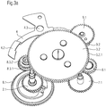
figure 3a montre une vue en perspective schématique de dessus d'un dispositif de rattrapante à train épicycloïdale selon la présente invention, lorsque le dispositif se trouve dans une première position de fonctionnement dans laquelle l'aiguille de rattrapante est libérée, lafigure 3b représente une vue en perspective schématique de dessous du dispositif se trouvant dans la première position de fonctionnement selon lafigure 3a , permettant d'apercevoir la coopération entre le levier de commande et le coeur sur la roue limitrophe, et lafigure 3c est une vue en perspective schématique de dessus du dispositif de rattrapante à train épicycloïdale de lafigure 3a , lorsque le dispositif se trouve dans une deuxième position de fonctionnement dans laquelle l'aiguille de rattrapante est bloquée. - La
figure 4 montre, par une vue de dessus schématique, un moyen d'annulation de jeu disposé entre la roue de chronographe et la roue de rattrapante d'un dispositif de rattrapante à train épicycloïdale selon la présente invention. - Les
figures 5a à 5f montrent, par des vues de dessus schématiques, différentes étapes de l'affichage telles que produites lors du fonctionnement d'une pièce d'horlogerie équipée d'un mécanisme de chronographe ainsi que d'un dispositif de rattrapante à train épicycloïdale selon la présente invention.
- The
figure 1 shows a diagrammatic perspective view from above of an epicyclic gear retractor device according to the present invention, when the device is integrated, for example, in a chronograph watch, the parts of the chronograph mechanism being indicated only 'for exemple. - The
figure 2a shows a perspective view from above, without the planet carrier, of the differential used in the epicyclic gear retractor device of thefigure 1 ; thefigure 2b represents a longitudinal section diagrammatically through this device. - The
figure 3a shows a diagrammatic perspective view from above of an epicyclic train retractor device according to the present invention, when the device is in a first operating position in which the split-second needle is released, thefigure 3b represents a perspective view schematic from below the device in the first operating position according to thefigure 3a , allowing to see the cooperation between the control lever and the heart on the boundary wheel, and thefigure 3c is a schematic perspective view from above of the epicyclic gear splitter device of thefigure 3a when the device is in a second operating position in which the split-second needle is locked. - The
figure 4 shows, in a schematic top view, a game cancellation means disposed between the chronograph wheel and the split wheel of an epicyclic gear retractor device according to the present invention. - The
Figures 5a to 5f show, by diagrammatic top views, different stages of the display as produced during the operation of a timepiece equipped with a chronograph mechanism as well as an epicyclic train retractor device according to the present invention .
L'invention sera maintenant décrite en détail en référence aux dessins annexés illustrant à titre d'exemple une forme d'exécution de l'invention.The invention will now be described in detail with reference to the accompanying drawings illustrating by way of example an embodiment of the invention.
La présente invention se rapporte à un dispositif de rattrapante à train épicycloïdale destiné à être intégré dans une pièce d'horlogerie, de préférence dans une montre bracelet ayant un mouvement mécanique, et plus particulièrement dans une montre chronographe. Pour des raisons de simplification du langage utilisé, on parlera par la suite indifféremment de « pièce d'horlogerie » et de « montre », sans pour autant vouloir limiter la portée des explications correspondantes qui s'étendent dans tous les cas à tout type de pièces d'horlogerie, ayant soit une source d'énergie mécanique soit électrique. De plus, un tel dispositif de rattrapante à train épicycloïdale peut être intégré dans des modules d'une telle pièce d'horlogerie, tel qu'un mécanisme de chronographe ou d'autres mécanismes qui sont susceptibles d'être équipés d'un dispositif de rattrapante à train épicycloïdale selon la présente invention. Si le dispositif de rattrapante à train épicycloïdale selon la présente invention sera par la suite décrit, à titre d'exemple, dans le contexte d'un mécanisme de chronographe, cela ne limite pas la portée de protection pour cette invention, car une intégration à d'autres types de pièces d'horlogerie est faisable par analogie. Du fait qu'un mécanisme de chronographe, voire d'autres mécanismes similaires qui sont adaptés à être combinés avec le dispositif de rattrapante à train épicycloïdale selon l'invention, sont en soi connus à l'homme du métier, la description suivante se limitera principalement et dans la mesure possible à la structure et au fonctionnement dudit dispositif de rattrapante à train épicycloïdale.The present invention relates to a retraction device with an epicyclic gear train intended to be integrated in a timepiece, preferably in a wristwatch having a mechanical movement, and more particularly in a chronograph watch. For reasons of simplification of the language used, we will speak indifferently later of "timepiece" and "watch", without wanting to limit the scope of the corresponding explanations which extend in all cases to any type of timepieces, having either a source of mechanical or electrical energy. In addition, such an epicyclic gear retractor device can be integrated into modules of such a timepiece, such as a chronograph mechanism or other mechanisms that are likely to be equipped with a device. epicyclic gear retractor according to the present invention. If the epicyclic retracting device according to the present invention will subsequently be described, by way of example, in the context of a chronograph mechanism, this does not limit the scope of protection for this invention, since an integration with other types of timepieces are feasible by analogy. Since a chronograph mechanism, or even other similar mechanisms which are adapted to be combined with the epicyclic retracting device according to the invention, are in themselves known to those skilled in the art, the following description will be limited to mainly and as far as possible to the structure and operation of said epicyclic gear splitter device.
Afin de commenter d'abord la structure et les composants d'un dispositif de rattrapante à train épicycloïdale selon la présente invention, on se réfère aux
Tel que cela ressort de la
Comme illustré également aux
De préférence, le dispositif comprend également une roue d'écart 7.1 liée cinématiquement au deuxième mobile de sortie 3.3 et portant une aiguille d'écart 7.2, ainsi qu'une roue intermédiaire 6.1 liée cinématiquement au deuxième mobile de sortie 3.3, la roue intermédiaire 6.1 engrenant avec ladite une roue d'écart 7.1. De préférence, une roue limitrophe 9.1 est agencée sur la périphérie du deuxième mobile de sortie 3.3 de sorte à engrener avec ce dernier et porte un coeur 9.2. Alternativement, ledit coeur pourrait être monté sur la roue intermédiaire 6.1 ou sur la roue d'écart 7.1. En effet, l'utilisation d'une roue intermédiaire 6.1 ou d'un rouage similaire, respectivement d'une roue limitrophe 9.1 permet de placer la roue d'écart 7.1, respectivement le coeur 9.2 à un endroit souhaité, respectivement sur un axe indépendant qui peut être renforcé, mais l'utilisation de ces pièces optionnelles n'est pas nécessaire.Preferably, the device also comprises a clearance wheel 7.1 kinematically connected to the second output mobile device 3.3 and carrying a shift needle 7.2, as well as an intermediate wheel 6.1 kinematically connected to the second output mobile device 3.3, the intermediate wheel 6.1 meshing with said a gap wheel 7.1. Preferably, a boundary wheel 9.1 is arranged on the periphery of the second output mobile 3.3 so as to mesh with the latter and carries a core 9.2. Alternatively, said core could be mounted on the intermediate wheel 6.1 or the clearance wheel 7.1. Indeed, the use of an intermediate wheel 6.1 or a similar wheel, respectively of a neighboring wheel 9.1 makes it possible to place the clearance wheel 7.1, respectively the core 9.2 at a desired location, respectively on an independent axis which can be reinforced, but the use of these optional parts is not necessary.
Les
Il est évident à l'homme du métier que le différentiel du dispositif de rattrapante 10 selon la présente invention peut être agencé différemment sans que cela aurait une influence substantielle à la structure ou au fonctionnement du dispositif. En outre, il est possible d'échanger non seulement la structure du mobile d'entrée 3.1 et des mobiles de sortie 3.2, 3.3, étant donné que de nombreux types de différentiel sont connus à l'homme du métier, mais également la fonction de ces mobiles. Par exemple, le mobile d'entrée 3.1 pourrait agir en tant que mobile de sortie, et la fonction des mobiles de sortie 3.2, 3.3 pourrait bien évidemment être inversée, en connectant le premier mobile de sortie 3.2 par l'intermédiaire de la roue intermédiaire 6.1 à la roue d'écart 7.1 et le deuxième mobile de sortie 3.3 au pignon de rattrapante 2.1. De même, le levier de commande 4 pourrait être remplacé par un autre moyen de commande équivalent apte à coopérer de manière similaire avec le poussoir de rattrapante. En variante, il est aussi possible d'agencer le coeur 9.2 sur la roue d'écart 7.1 ou sur le pignon de rattrapante 2.1, mais ces constellations sont moins préférées car le levier 4 agit comme un marteaux agissant de manière répétitive sur le coeur 6.2. La forme d'exécution préférée permet d'éviter de placer le coeur 6.2 sur un axe fin comme celui de l'aiguille de rattrapante.It is obvious to those skilled in the art that the differential of the
D'autres modifications sont possibles au niveau des rouages réalisant les différents liaisons cinématiques mentionnées ci-dessus. En outre, la liaison cinématique entre la roue de chronographe 8.1 et le mobile d'entrée 3.1 du différentiel 3 est, dans la forme d'exécution préférée illustrée aux figures, réalisée par l'intermédiaire d'un premier pignon intermédiaire 8.3 ayant une première denture 8.3.1 engrenant avec la roue de chronographe 8.1 et une deuxième denture 8.3.2 engrenant avec une deuxième pignon intermédiaire 8.4, ce dernier engrenant avec le mobile d'entrée 3.1. Si cette solution permet de choisir de manière particulièrement facile le rapport d'engrenage entre la roue de chronographe 8.1 et le mobile d'entrée 3.1, il est pourtant également possible que la roue de chronographe 8.1 engrène directement avec le mobile d'entrée 3. De façon analogique, il est possible de prévoir un rouage intermédiaire qu lieu que le porte-satellites 3.2 engrène directement avec le pignon de rattrapante 2.1, et d'utiliser par exemple ce rouage intermédiaire pour placer le coeur 9.2, en fonction de l'utilisation de parties du différentiel 3 en tant qu'entrée, respectivement sortie.Other modifications are possible in the gear trains performing the different kinematic links mentioned above. In addition, the kinematic connection between the chronograph wheel 8.1 and the input mobile 3.1 of the differential 3 is, in the preferred embodiment illustrated in the figures, carried out via a first intermediate gear 8.3 having a first 8.3.1 gear meshing with the chronograph wheel 8.1 and a second gear 8.3.2 meshing with a second intermediate gear 8.4, the latter meshing with the mobile input 3.1. If this solution makes it possible to choose in a particularly easy way the gear ratio between the chronograph wheel 8.1 and the mobile input 3.1, it is nevertheless also possible that the chronograph wheel 8.1 meshes directly with the
Par ailleurs, un dispositif de rattrapante à train épicycloïdale selon la présente invention est, de préférence, équipé d'un moyen d'annulation de jeu 5 disposé entre la roue de chronographe et la roue de rattrapante, tel qu'illustré à la
Les explications précédentes concernant la structure et les composants d'un dispositif de rattrapante à train épicycloïdale 10 selon la présente invention ainsi que son application dans un mécanisme de chronographe permettent de comprendre facilement son fonctionnement, notamment à l'aide des séries de
Lorsque l'utilisateur de la pièce d'horlogerie actionne le poussoir de rattrapante, ce dernier pousse le levier de commande 4 dans sa deuxième position dans laquelle il bloque le premier mobile de sortie 3.2. Dans cette position, illustrée à la
Lorsque l'utilisateur de la pièce d'horlogerie actionne de nouveau le poussoir de rattrapante, le levier de commande 4 revient dans sa première position dans laquelle la zone d'appui 4.1.1 de la première extrémité libre 4.1 de ce levier 4 appui sur le coeur 9.2, en libérant le porte-satellites 3.2, respectivement en bloquant la couronne 3.3. Avant que le blocage de la couronne 3.3 soit actif, l'appui progressif du levier 4 sur le coeur 9.2 solidaire de la roue limitrophe 9.1 fait revenir le coeur 9.2 dans sa position de repos dans laquelle ladite zone d'appui 4.1.1 de la première extrémité libre 4.1 du levier 4 est en face de la partie plate du coeur 9.2 et qui définit la position dans laquelle l'aiguille de chronographe 8.2 et l'aiguille de rattrapante 2.2 sont superposées. La roue limitrophe 9.1 effectue alors une rotation d'une distance angulaire qui correspond à l'écart entre l'aiguille de chronographe 8.2 et l'aiguille de rattrapante 2.2. Cela entraîne la couronne 3.3 qui fait tourner à son tour le porte-satellites 3.2, étant donné que le pignon solaire 3.1.2 est sécurisé dans sa position angulaire par la roue solaire 3.1.1 engrenant avec la roue de chronographe 8.1. Le porte-satellites 3.2 fait tourner le pignon de rattrapante 2.1, de sorte à ce que l'aiguille de rattrapante 2.2 « rattrape » l'aiguille de chronographe 8.2 et se trouve de nouveau en superposition avec l'aiguille de chronographe 8.2. Simultanément, la roue intermédiaire 6.1, liée à la roue limitrophe 9.1 par l'intermédiaire de la denture extérieure 3.3.1 de la couronne 3.3, fait tourner la roue d'écart 7.1, de sorte à ce que l'aiguille d'écart 7.2 retourne dans sa position de repos, indiquant un écart zéro entre l'aiguille de rattrapante 2.2 et l'aiguille de chronographe 8.2. Le coeur 9.2 étant sensiblement symétrique, le rattrape peut avoir lieu dans les deux sens de rotation, mais s'effectue toujours automatiquement dans le sens de rotation où l'aiguille de rattrapante 2.2 parcourt le chemin le plus court. Une fois que le coeur 9.2 ainsi que l'aiguille de rattrapante 2.2 et l'aiguille d'écart 7.2 sont dans leurs positions de repos respectives, le dispositif de rattrapante 10 est prêt pour un nouvel actionnement.When the user of the timepiece actuates the split-back push-button again, the
Les
La présente invention concerne également un mécanisme de chronographe, destiné à être intégré dans une montre chronographe, comprenant une roue de chronographe 8.1 portant une aiguille de chronographe 8.2, ladite roue de chronographe 8.1 pouvant être entraînée à partir d'une roue d'entraînement d'un rouage de finissage du mouvement de la montre chronographe, et un moyen de commande permettant de démarrer et d'arrêter la mesure d'un temps chronométré. Un tel mécanisme de chronographe selon la présente invention devrait comprendre au moins un dispositif de rattrapante à train épicycloïdale 10 tel que décrit ci-dessus, chaque aiguille de rattrapante 2.2 étant montée de façon librement rotative autour de l'axe de rotation 1 de l'aiguille de chronographe 8.2 correspondante. En effet, il est possible d'équiper, par exemple, qu'une aiguille de secondes de chronographe d'une aiguille de rattrapante, mais il est aussi possible d'en équiper toutes les aiguilles du chronographe si ce dernier comporte également une aiguille de minutes de chronographe et une aiguille d'heures de chronographe. À ce fin, le mécanisme de chronographe peut être équipé de plusieurs dispositifs de rattrapante à train épicycloïdale 10, chacun commandant une seule aiguille de rattrapante, ou d'un seul dispositif de rattrapante à train épicycloïdale 10 qui commande toutes les aiguilles de rattrapante en prévoyant une liaison cinématique à rapport d'engrenage adéquat entre les pignons de rattrapante correspondants.The present invention also relates to a chronograph mechanism, intended to be integrated in a chronograph watch, comprising a chronograph wheel 8.1 carrying a chronograph hand 8.2, said chronograph wheel 8.1 being drivable from a drive wheel of a chronograph a finishing gear of the movement of the chronograph watch, and a control means for starting and stopping the measurement of a timed time. Such a chronograph mechanism according to the present invention should comprise at least one epicyclic
Enfin, la présente invention concerne également une pièce d'horlogerie, notamment une montre bracelet mécanique, qui comprend au moins un dispositif de rattrapante à train épicycloïdale 10 ou un mécanisme de chronographe tel que décrit ci-dessus. En particulier, il peut s'agir non seulement d'une pièce d'horlogerie équipée d'un chronographe, mais également d'un autre type de pièce d'horlogerie, par exemple d'une montre bracelet mécanique comprenant simplement une aiguille d'heures, une aiguille de minutes, et/ou une aiguille de secondes. Dans ce cas, la pièce d'horlogerie peut comprendre au moins un dispositif de rattrapante à train épicycloïdale 10 selon la présente invention, chaque aiguille de rattrapante 2.2 étant montée de façon librement rotative autour de l'axe de rotation 1 d'une des aiguilles d'heures, de minutes, et/ou de secondes de ladite pièce d'horlogerie. Cela peut par exemple permettre de marquer, en appuyant une première fois sur le poussoir de rattrapante, l'heure exacte du début d'un évènement au cours de la journée par l'intermédiaire de l'aiguille de rattrapante 2.2, la durée de l'évènement étant simultanément affichée par l'aiguille d'écart 7.2. À la fin de l'évènement, il suffit, en appuyant une deuxième fois sur le poussoir de rattrapante, de faire revenir l'aiguille de rattrapante 2.2 dans sa position superposée avec l'aiguille correspondante afin de revenir à un mode normal d'affichage de temps.Finally, the present invention also relates to a timepiece, in particular a mechanical wristwatch, which comprises at least one epicyclic gear retractor device or a chronograph mechanism as described above. In particular, it may be not only a timepiece equipped with a chronograph, but also another type of piece horological watch, for example a mechanical wristwatch simply comprising an hour hand, a minute hand, and / or a seconds hand. In this case, the timepiece may comprise at least one epicyclic
Vu l'agencement et le fonctionnement du dispositif décrit ci-dessus, on comprend qu'un dispositif de rattrapante à train épicycloïdale selon la présente invention permet d'entrainer ou de bloquer une aiguille de rattrapante, par exemple d'un chronographe d'une montre mécanique, à l'aide d'un système planétaire placé entre la source d'énergie de la pièce d'horlogerie et le pignon de l'aiguille de rattrapante. Le différentiel permet de réaliser simultanément et de manière relativement simple une fonction similaire à celle de l'isolateur des mécanismes de rattrapante conventionnels, limitant les effets néfastes de la présence d'une aiguille de rattrapante sur la précision de marche de la pièce d'horlogerie équipée de ce dispositif. Lorsque le dispositif comprend également une roue d'écart portant une aiguille d'écart ainsi qu'une roue limitrophe portant un coeur et/ou une roue intermédiaire, le dispositif permet aussi, d'une part, de faire appuyer les marteaux nécessaires dans ce genre de mécanisme à d'autres axes que les axes fins portant les aiguilles, ainsi que, d'autre part, d'intégrer dans un mécanisme de rattrapante une fonction supplémentaire, à savoir l'affichage de l'écart de temps entre l'aiguille de rattrapante et l'aiguille correspondante, par exemple l'aiguille de chronographe, lorsque l'aiguille de rattrapante est arrêtée. En même temps, il est doté d'une structure robuste et d'un fonctionnement sûr et fiable. Ces avantages sont obtenus tout en garantissant que le dispositif de rattrapante à train épicycloïdale selon la présente invention peut être utilisé pour plusieurs applications et dispose donc d'une certaine flexibilité. En particulier, ce dispositif de rattrapante à train épicycloïdale peut avantageusement être intégré dans des montres chronographes ou simplement dans des montres dotées que d'un affichage de temps normal. En général, le dispositif peut être intégré dans toute sorte de pièces d'horlogerie, de préférence dans des montres bracelet mécaniques, mais il est aussi possible de l'utiliser dans des montres électroniques.In view of the arrangement and operation of the device described above, it will be understood that an epicycloidal retracting device according to the present invention makes it possible to drive or block a catch-up needle, for example a chronograph of a mechanical watch, using a planetary system placed between the energy source of the timepiece and the pinion of the split-second hand. The differential makes it possible to carry out simultaneously and in a relatively simple manner a function similar to that of the insulator of conventional override mechanisms, limiting the detrimental effects of the presence of a split-second needle on the running accuracy of the timepiece. equipped with this device. When the device also comprises a deviation wheel carrying a deviating needle and a boundary wheel carrying a core and / or an intermediate wheel, the device also makes it possible, on the one hand, to have the necessary hammers supported in this device. kind of mechanism to other axes than the fine axes carrying the needles, as well as, on the other hand, to integrate into a A further function of the split-back mechanism is to display the time difference between the split-second hand and the corresponding hand, for example the chronograph hand, when the split-second hand is stopped. At the same time, it has a robust structure and a safe and reliable operation. These advantages are achieved while ensuring that the epicycloidal retracting device according to the present invention can be used for several applications and therefore has some flexibility. In particular, this retraction device with epicyclic gear can advantageously be integrated in chronograph watches or simply in watches equipped with a normal time display. In general, the device can be integrated into any kind of timepiece, preferably in mechanical wristwatches, but it is also possible to use it in electronic watches.
Claims (12)
- A split-seconds device (10) for a timepiece, in particular for a chronograph watch, the device having a split-seconds pinion (2.1) which carries a fly-back hand (2.2) and is mounted such as to rotate freely about a rotation arbor (1) of said timepiece, characterised in that the device comprises a differential (3) having an entry wheel (3.1) adapted to be kinematically connected to a power source of the timepiece, a first exit wheel (3.2) kinematically connected to the entry wheel (3.1) by at least one planetary wheel (3.4) and meshing with the split-seconds pinion (2.1), a second exit wheel (3.3) kinematically connected to said entry wheel (3.1) by said at least one planetary wheel (3.4), and a control lever (4) allowing to block either the first exit wheel (3.2) or the second exit wheel (3.3), such that whichever of the first exit wheel (3.2) and the second exit wheel (3.3) is released by the control lever (4) is adapted to be driven by said entry wheel (3.1) when the latter is kinematically connected to the power source of the timepiece, thus allowing to block or respectively release said fly-back hand (2.2).
- The split-seconds device according to the preceding claim, characterised in that the control lever (4) allowing to block either the first exit wheel (3.2) or the second exit wheel (3.3) is prestressed by a retaining spring in a first position in which the lever (4) blocks the second exit wheel (3.3), such that the fly-back hand (2.2) is released, the lever (4) being adapted to be brought by the user of the timepiece into a second position in which the lever (4) blocks the first exit wheel (3.2), such that the fly-back hand (2.2) is blocked.
- The split-seconds device according to one of the preceding claims, characterised in that the device comprises a difference wheel (7.1) kinematically connected to the second exit wheel (3.3) and carrying a difference hand (7.2).
- The split-seconds device according to the preceding claim, characterised in that the device comprises an intermediate wheel (6.1) kinematically connected to the second exit wheel (3.3) and meshing with said difference wheel (7.1).
- The split-seconds device according to the preceding claim, characterised in that the device comprises an adjacent wheel (9.1) kinematically connected to the second exit wheel (3.3) and carrying a heart (9.2) adapted to cooperate with said lever (4).
- The split-seconds device according to one of the preceding claims, characterised in that the entry wheel (3.1) of the differential (3) is formed by a sun wheel (3.1.1) secured to a sun pinion (3.1.2), the first exit wheel (3.2) being formed by a planet carrier (3.2) mounted such as to rotate freely about the arbor of the differential (3) and carrying at least one planetary wheel (3.4) meshing with said sun pinion (3.1.2), the second exit wheel (3.3) being formed by an outer toothing (3.3.1) of a crown (3.3) mounted such as to rotate freely about the arbor of the differential (3) and meshing by means of an inner toothing (3.3.2) with said at least one planetary wheel (3.4).
- The split-seconds device according to one of the preceding claims 3 to 6, characterised in that the outer toothing (3.3.1) of said crown (3.3) forming the second exit wheel (3.3) meshes with said intermediate wheel (6.1) which meshes in turn with the difference wheel (7.1), thus realizing the kinematic connection between the difference wheel (7.1) and the second exit wheel (3.3).
- The split-seconds device according to the preceding claim, characterised in that the control lever (4), in the first position thereof in which the lever (4) is prestressed by a retaining spring and blocks the second exit wheel (3.3), rests on the heart (9.2) secured to the adjacent wheel (9.1) such that the crown (3.3) is blocked and the split-seconds hand (2.2) is released, and, in the second position thereof in which the lever (4) blocks the first exit wheel (3.2), rests on the outer toothing of the planet carrier (3.2) such that the planet carrier (3.2) and the fly-back hand (2.2) are blocked, simultaneously releasing said difference hand (7.2).
- The split-seconds device according to one of the preceding claims, characterised in that it comprises a play-cancelling means (5) having a support (5.1) in the form of a disc secured to the chronograph wheel (8.1) and carrying a jumper (5.2) of substantially circular shape, as well as an eccentric (5.4) of substantially elliptical shape and secured to the split-seconds wheel (2.1), a first free end (5.2.1) of the jumper (5.2) forming a short arm equipped with a rounded addendum (5.2.1.1) and a second free end (5.2.2) of the jumper (5.2) forming a long arm forming an extended arc of a circle cooperating with pins (5.3) mounted on said support (5.1), the eccentric (5.4) comprising, at the end of its major axis distanced farthest from the centre of rotation of the eccentric (5.4), a rounded notch (5.4.1) adapted to cooperate with the rounded addendum (5.2.1.1) formed on the first free end (5.2.1) of the jumper (5.2).
- A chronograph mechanism, intended to be integrated in a chronograph watch, comprising a chronograph wheel (8.1) carrying a chronograph hand (8.2), said chronograph wheel (8.1) being adapted to be driven by a driving wheel of a geartrain of the movement of the chronograph watch, and a control means allowing to start and stop the measurement of a timed period, characterised in that it comprises at least one split-seconds device with epicycloidal train (10) according to one of the preceding claims, each fly-back hand (2.2) being mounted such as to rotate freely about the rotation arbor (1) of said chronograph hand (8.2).
- A timepiece, in particular a mechanical wristwatch, characterised in that it comprises at least one split-seconds device with epicycloidal train (10) according to one of the preceding claims 1 to 9 and/or a chronograph mechanism according to the preceding claim 10.
- A timepiece, in particular a mechanical wristwatch, comprising an hours hand, a minutes hand, and/or a seconds hand, characterised in that it comprises at least one split-seconds device with epicycloidal train (10) according to one of the preceding claims 1 to 9, each fly-back hand (2.2) being mounted such as to rotate freely about the rotation arbor (1) of an hours, minutes and/or seconds hand of said timepiece.
Applications Claiming Priority (1)
| Application Number | Priority Date | Filing Date | Title |
|---|---|---|---|
| CH01760/14A CH710362A1 (en) | 2014-11-13 | 2014-11-13 | Device to split planetary gear for a timepiece. |
Publications (2)
| Publication Number | Publication Date |
|---|---|
| EP3021175A1 EP3021175A1 (en) | 2016-05-18 |
| EP3021175B1 true EP3021175B1 (en) | 2017-02-08 |
Family
ID=54238357
Family Applications (1)
| Application Number | Title | Priority Date | Filing Date |
|---|---|---|---|
| EP15187312.2A Active EP3021175B1 (en) | 2014-11-13 | 2015-09-29 | Split-seconds device with epicycloidal train for a timepiece |
Country Status (7)
| Country | Link |
|---|---|
| US (1) | US9477206B2 (en) |
| EP (1) | EP3021175B1 (en) |
| JP (1) | JP6603553B2 (en) |
| CN (1) | CN105607456B (en) |
| CH (1) | CH710362A1 (en) |
| ES (1) | ES2621572T3 (en) |
| HK (1) | HK1218446A1 (en) |
Families Citing this family (9)
| Publication number | Priority date | Publication date | Assignee | Title |
|---|---|---|---|---|
| USD814946S1 (en) * | 2016-10-18 | 2018-04-10 | Audemars Piguet (Marketing) Sa | Watch |
| EP3495895B1 (en) * | 2017-12-11 | 2022-02-23 | Omega SA | Mechanism for sound display of a timepiece, in particular chronograph repetition |
| EP3547045B1 (en) * | 2018-03-26 | 2022-05-04 | Montres Breguet S.A. | Timepiece transmission mechanism having reduced clutching effort |
| US11733652B2 (en) * | 2018-04-30 | 2023-08-22 | Rolex Sa | Horological display system |
| EP3605243A1 (en) * | 2018-07-31 | 2020-02-05 | Montres Breguet S.A. | Variable geometry timepiece display mechanism with elastic needle |
| EP3667435B1 (en) * | 2018-12-10 | 2022-06-01 | Montres Breguet S.A. | System for adjusting the position of a first toothed moving part relative to a support on which the first toothed moving part is pivotably mounted, and timepiece comprising such a system |
| EP3944026A1 (en) * | 2020-07-21 | 2022-01-26 | Rolex Sa | Timepiece mechanism with counting chain |
| CH718037A2 (en) * | 2020-11-05 | 2022-05-13 | Timeforge Sarl | Digital display mechanism for split-seconds chronograph and chronograph comprising such a mechanism. |
| KR20240025903A (en) * | 2022-08-19 | 2024-02-27 | 심웅대 | second hand |
Family Cites Families (44)
| Publication number | Priority date | Publication date | Assignee | Title |
|---|---|---|---|---|
| CH3914A (en) | 1891-07-10 | 1892-02-15 | Piguet William Alfred | Rattrapante with insulator |
| CH6180A (en) | 1893-01-07 | 1893-08-15 | Droz Paul Louis | Double-acting mechanism for simple chronograph watches, split-seconds chronograph watches, counter chronograph watches, etc. |
| CH7411A (en) | 1893-10-10 | 1894-05-31 | Reymond Rod & Aeschlimann | Chronograph movement with rattrapante mechanism under the dial |
| CH10027A (en) | 1895-04-03 | 1895-09-30 | Meylan Ami Auguste | Split-seconds isolator stop for chronograph watches |
| CH11853A (en) | 1896-01-07 | 1896-08-31 | Lugrin Henry Alfred | Perfected instrument for controlling the speed of men and horses during races, trotting or walking events, etc. |
| CH27052A (en) | 1902-11-13 | 1903-12-15 | Ancienne Manufacture D Horloge | Double chronograph |
| CH165556A (en) | 1930-09-11 | 1933-11-30 | Vial Jules | Device for measuring time differences. |
| GB388258A (en) * | 1931-05-13 | 1933-02-23 | Marcel Vuilleumier | Improvements relating to horological movements |
| CH216001A (en) | 1939-08-22 | 1941-07-31 | Sonceboz Sa | Chronograph timepiece. |
| CH260791A (en) | 1947-02-04 | 1949-03-31 | Dubey Georges | Split-seconds chronograph. |
| CH278478A (en) | 1948-06-14 | 1951-10-15 | Dubey Georges | Split-seconds chronograph. |
| FR1164020A (en) | 1956-12-27 | 1958-10-06 | Epicyclic train with large reduction ratio and its application to watchmaking manufacturing | |
| JP2646946B2 (en) * | 1992-12-02 | 1997-08-27 | セイコーエプソン株式会社 | clock |
| FR2772153B1 (en) | 1997-12-08 | 2000-02-18 | Formes Technologie Innovation | NEEDLE DISPLAY WATCH WITH MOBILE MINUTES DIAL |
| US6434086B1 (en) * | 1998-07-03 | 2002-08-13 | Citizen Watch Co., Ltd. | Analog electronic timepiece |
| CH693155A5 (en) * | 1998-11-04 | 2003-03-14 | Andreas Strehler | Timepiece display mechanism has single display organ switched between alternate display modes |
| DE69940727D1 (en) | 1999-08-04 | 2009-05-28 | Piguet Frederic Sa | Device for displaying the power reserve of a watch |
| ATE418752T1 (en) * | 2001-03-21 | 2009-01-15 | Chronoswiss Uhren Gmbh | CLOCKWORK |
| DE60226132T2 (en) | 2002-06-13 | 2009-05-28 | Vaucher Manufacture Fleurier S.A. | Chronograph mechanism |
| CN2593237Y (en) * | 2002-12-21 | 2003-12-17 | 杭州手表有限公司 | Flyback dual second-hand indicating mechanism |
| DE602004016282D1 (en) * | 2004-04-01 | 2008-10-16 | Richemont Int Sa | Movement with several barrels |
| DE102004017345B3 (en) | 2004-04-06 | 2005-09-01 | Lange Uhren Gmbh | Stopwatch with mechanism for starting and stopping second hand and minute hand for timing events has heart-shaped cam on minute wheel for synchronization of minute indicator with minute hand |
| JP4846781B2 (en) * | 2005-03-23 | 2011-12-28 | ベエヌベ コンセプ エセア | Watch movement |
| CN2833660Y (en) * | 2005-04-29 | 2006-11-01 | 上海新港表业有限公司 | Multi-second-hand bouncing return mechanism |
| EP1777598B1 (en) | 2005-10-21 | 2012-02-15 | Rolex Sa | Timepiece with a mechanism to measure adjustable predetermined times |
| EP1818738A3 (en) | 2006-02-14 | 2011-05-11 | Franck Müller Watchland SA | Four hundred year perpetual calendar |
| DE102006008700B3 (en) | 2006-02-24 | 2007-08-30 | Heitzer, Heinz-Dieter, Dr. | Adjusting device for adjusting pointer position with mechanical clocks, has inhibition mechanism coupled with motion work, and planet gear holder is implemented as separate housing part and is pivot mounted on clockwork housing |
| EP1921524A1 (en) * | 2006-11-07 | 2008-05-14 | Manufacture Roger Dubuis S.A. | Mit einem Chronographenmechanismus ausgerüstete mechanische Uhr |
| DE602007006151D1 (en) | 2007-02-14 | 2010-06-10 | Maurice Lacroix Sa | Mechanism for switchable transmission |
| JP5210557B2 (en) * | 2007-07-12 | 2013-06-12 | シチズン時計株式会社 | clock |
| CH706021B1 (en) | 2007-11-21 | 2013-07-31 | Frank Mueller Watchland S A | watch movement type and chronograph timepiece provided with such a movement. |
| ES2401928T3 (en) | 2008-04-23 | 2013-04-25 | Société Anonyme de la Manufacture d'Horlogerie Audemars Piguet & Cie | Clutch device |
| CH698906B1 (en) | 2008-05-21 | 2014-12-31 | Christophe Claret S A | chronograph mechanism. |
| CH705769B1 (en) | 2008-06-05 | 2013-05-31 | Manuf La Joux Perret Sa | wristwatch chronograph movement comprising two split-system. |
| CH700302A2 (en) * | 2009-01-21 | 2010-07-30 | Montblanc Simplo Gmbh | Chronograph. |
| CH700512A2 (en) * | 2009-03-13 | 2010-09-15 | Richemont Int Sa | Chronograph with adjustable countdown display. |
| CH702808B1 (en) | 2010-03-05 | 2015-03-13 | Manuf La Joux Perret Sa | Chronograph. |
| CH702992A1 (en) | 2010-04-23 | 2011-10-31 | Francois-Regis Richard | Chronograph mechanism for clockwork movement utilized to drive i.e. needle, to display chronometered time, has counter associated with display member and arranged in such way that mobile part exhibits relative movement with counter |
| CH703008A1 (en) | 2010-04-23 | 2011-10-31 | Francois-Regis Richard | Mechanism chronographe, clock and movement timepiece including such mechanism. |
| EP2410388B1 (en) | 2010-07-21 | 2018-04-18 | Blancpain S.A. | Time piece with double display |
| CH704120B1 (en) | 2010-11-18 | 2015-11-13 | Temps S A Fab Du | differential chronograph to measure and indicate two distinct time and the difference of these two times. |
| EP2515186B1 (en) | 2011-04-20 | 2014-06-11 | Cartier Création Studio S.A. | Räderwerk für Uhr |
| CN103064276B (en) * | 2011-10-21 | 2013-11-13 | 天王电子(深圳)有限公司 | Double-eccentric mechanical watch |
| JP6564561B2 (en) * | 2013-05-31 | 2019-08-21 | ロレックス・ソシエテ・アノニムRolex Sa | Clock mechanism for storing and displaying time information |
-
2014
- 2014-11-13 CH CH01760/14A patent/CH710362A1/en not_active Application Discontinuation
-
2015
- 2015-09-29 ES ES15187312.2T patent/ES2621572T3/en active Active
- 2015-09-29 EP EP15187312.2A patent/EP3021175B1/en active Active
- 2015-11-05 US US14/934,003 patent/US9477206B2/en active Active
- 2015-11-12 CN CN201510767764.8A patent/CN105607456B/en active Active
- 2015-11-12 JP JP2015222162A patent/JP6603553B2/en active Active
-
2016
- 2016-06-06 HK HK16106448.7A patent/HK1218446A1/en unknown
Also Published As
| Publication number | Publication date |
|---|---|
| JP2016109680A (en) | 2016-06-20 |
| ES2621572T3 (en) | 2017-07-04 |
| JP6603553B2 (en) | 2019-11-06 |
| EP3021175A1 (en) | 2016-05-18 |
| HK1218446A1 (en) | 2017-02-17 |
| CN105607456B (en) | 2019-07-26 |
| CH710362A1 (en) | 2016-05-13 |
| US9477206B2 (en) | 2016-10-25 |
| US20160139567A1 (en) | 2016-05-19 |
| CN105607456A (en) | 2016-05-25 |
Similar Documents
| Publication | Publication Date | Title |
|---|---|---|
| EP3021175B1 (en) | Split-seconds device with epicycloidal train for a timepiece | |
| EP2548084B1 (en) | Movement for a timepiece with equalizing winding mechanism | |
| EP2073076B1 (en) | Alarm clock control mechanism | |
| EP3584643B1 (en) | Instantaneous command device for date display of timepieces | |
| EP0008832A2 (en) | Clockwork with hands comprising a differential-gear mechanism | |
| EP3382468B1 (en) | Movement with extension of running reserve | |
| CH710118A2 (en) | Corps gear, adjusting mechanism of a time difference, clock movement, and timepiece. | |
| WO2016155814A1 (en) | Mechanism for rewinding and/or correcting at least one clock function and device for selecting a clock function | |
| CH697433B1 (en) | Time piece i.e. chronograph watch, has rotative unit comprising lower stage for controlling movement of hammer, and upper stage cooperating with portion of whip for controlling displacement of whip during setting-up and stopping of motor | |
| EP3368950B1 (en) | Chronograph with countdown timer | |
| EP2281222B1 (en) | Display device | |
| EP2802945A1 (en) | Clockwork movement indicating mechanism that acts in response to a request for information | |
| EP2112564A1 (en) | Clutch device | |
| CH708001B1 (en) | Perpetual calendar calendar mechanism and display of the vintage. | |
| EP3701336B1 (en) | Correction device for a timepiece | |
| CH702846B1 (en) | Device for controlling and adjusting a watch movement. | |
| EP3252543A1 (en) | Display device for timepiece movement | |
| EP4254079A1 (en) | Mechanism for displaying the phases of the moon for a timepiece | |
| CH713658B1 (en) | Watch movement comprising two regulating members. | |
| EP2309348B1 (en) | Alarm device for timepieces | |
| EP3985448A1 (en) | System for driving and holding the position of a mobile for displaying a time or time-derived information | |
| EP1343057A2 (en) | Mechanical timepiece | |
| CH719557A2 (en) | Timepiece moon phase display mechanism. | |
| CH712032B1 (en) | Control mechanism for a watch movement. | |
| CH712597A1 (en) | Mechanism for watch movement with two regulating bodies. |
Legal Events
| Date | Code | Title | Description |
|---|---|---|---|
| PUAI | Public reference made under article 153(3) epc to a published international application that has entered the european phase |
Free format text: ORIGINAL CODE: 0009012 |
|
| AK | Designated contracting states |
Kind code of ref document: A1 Designated state(s): AL AT BE BG CH CY CZ DE DK EE ES FI FR GB GR HR HU IE IS IT LI LT LU LV MC MK MT NL NO PL PT RO RS SE SI SK SM TR |
|
| AX | Request for extension of the european patent |
Extension state: BA ME |
|
| 17P | Request for examination filed |
Effective date: 20160623 |
|
| RBV | Designated contracting states (corrected) |
Designated state(s): AL AT BE BG CH CY CZ DE DK EE ES FI FR GB GR HR HU IE IS IT LI LT LU LV MC MK MT NL NO PL PT RO RS SE SI SK SM TR |
|
| GRAP | Despatch of communication of intention to grant a patent |
Free format text: ORIGINAL CODE: EPIDOSNIGR1 |
|
| INTG | Intention to grant announced |
Effective date: 20161007 |
|
| GRAS | Grant fee paid |
Free format text: ORIGINAL CODE: EPIDOSNIGR3 |
|
| GRAA | (expected) grant |
Free format text: ORIGINAL CODE: 0009210 |
|
| AK | Designated contracting states |
Kind code of ref document: B1 Designated state(s): AL AT BE BG CH CY CZ DE DK EE ES FI FR GB GR HR HU IE IS IT LI LT LU LV MC MK MT NL NO PL PT RO RS SE SI SK SM TR |
|
| REG | Reference to a national code |
Ref country code: GB Ref legal event code: FG4D Free format text: NOT ENGLISH |
|
| REG | Reference to a national code |
Ref country code: CH Ref legal event code: EP Ref country code: AT Ref legal event code: REF Ref document number: 867137 Country of ref document: AT Kind code of ref document: T Effective date: 20170215 |
|
| REG | Reference to a national code |
Ref country code: CH Ref legal event code: NV Representative=s name: PER MENS INTELLECTUAL PROPERTY CONSULTING SARL, CH |
|
| REG | Reference to a national code |
Ref country code: IE Ref legal event code: FG4D Free format text: LANGUAGE OF EP DOCUMENT: FRENCH |
|
| REG | Reference to a national code |
Ref country code: DE Ref legal event code: R096 Ref document number: 602015001471 Country of ref document: DE |
|
| REG | Reference to a national code |
Ref country code: LT Ref legal event code: MG4D |
|
| REG | Reference to a national code |
Ref country code: NL Ref legal event code: MP Effective date: 20170208 |
|
| REG | Reference to a national code |
Ref country code: ES Ref legal event code: FG2A Ref document number: 2621572 Country of ref document: ES Kind code of ref document: T3 Effective date: 20170704 |
|
| REG | Reference to a national code |
Ref country code: AT Ref legal event code: MK05 Ref document number: 867137 Country of ref document: AT Kind code of ref document: T Effective date: 20170208 |
|
| PG25 | Lapsed in a contracting state [announced via postgrant information from national office to epo] |
Ref country code: LT Free format text: LAPSE BECAUSE OF FAILURE TO SUBMIT A TRANSLATION OF THE DESCRIPTION OR TO PAY THE FEE WITHIN THE PRESCRIBED TIME-LIMIT Effective date: 20170208 Ref country code: GR Free format text: LAPSE BECAUSE OF FAILURE TO SUBMIT A TRANSLATION OF THE DESCRIPTION OR TO PAY THE FEE WITHIN THE PRESCRIBED TIME-LIMIT Effective date: 20170509 Ref country code: NO Free format text: LAPSE BECAUSE OF FAILURE TO SUBMIT A TRANSLATION OF THE DESCRIPTION OR TO PAY THE FEE WITHIN THE PRESCRIBED TIME-LIMIT Effective date: 20170508 Ref country code: HR Free format text: LAPSE BECAUSE OF FAILURE TO SUBMIT A TRANSLATION OF THE DESCRIPTION OR TO PAY THE FEE WITHIN THE PRESCRIBED TIME-LIMIT Effective date: 20170208 Ref country code: FI Free format text: LAPSE BECAUSE OF FAILURE TO SUBMIT A TRANSLATION OF THE DESCRIPTION OR TO PAY THE FEE WITHIN THE PRESCRIBED TIME-LIMIT Effective date: 20170208 |
|
| PG25 | Lapsed in a contracting state [announced via postgrant information from national office to epo] |
Ref country code: SE Free format text: LAPSE BECAUSE OF FAILURE TO SUBMIT A TRANSLATION OF THE DESCRIPTION OR TO PAY THE FEE WITHIN THE PRESCRIBED TIME-LIMIT Effective date: 20170208 Ref country code: BG Free format text: LAPSE BECAUSE OF FAILURE TO SUBMIT A TRANSLATION OF THE DESCRIPTION OR TO PAY THE FEE WITHIN THE PRESCRIBED TIME-LIMIT Effective date: 20170508 Ref country code: AT Free format text: LAPSE BECAUSE OF FAILURE TO SUBMIT A TRANSLATION OF THE DESCRIPTION OR TO PAY THE FEE WITHIN THE PRESCRIBED TIME-LIMIT Effective date: 20170208 Ref country code: RS Free format text: LAPSE BECAUSE OF FAILURE TO SUBMIT A TRANSLATION OF THE DESCRIPTION OR TO PAY THE FEE WITHIN THE PRESCRIBED TIME-LIMIT Effective date: 20170208 Ref country code: PT Free format text: LAPSE BECAUSE OF FAILURE TO SUBMIT A TRANSLATION OF THE DESCRIPTION OR TO PAY THE FEE WITHIN THE PRESCRIBED TIME-LIMIT Effective date: 20170608 Ref country code: NL Free format text: LAPSE BECAUSE OF NON-PAYMENT OF DUE FEES Effective date: 20170208 Ref country code: LV Free format text: LAPSE BECAUSE OF FAILURE TO SUBMIT A TRANSLATION OF THE DESCRIPTION OR TO PAY THE FEE WITHIN THE PRESCRIBED TIME-LIMIT Effective date: 20170208 |
|
| REG | Reference to a national code |
Ref country code: FR Ref legal event code: PLFP Year of fee payment: 3 |
|
| PG25 | Lapsed in a contracting state [announced via postgrant information from national office to epo] |
Ref country code: RO Free format text: LAPSE BECAUSE OF FAILURE TO SUBMIT A TRANSLATION OF THE DESCRIPTION OR TO PAY THE FEE WITHIN THE PRESCRIBED TIME-LIMIT Effective date: 20170208 Ref country code: CZ Free format text: LAPSE BECAUSE OF FAILURE TO SUBMIT A TRANSLATION OF THE DESCRIPTION OR TO PAY THE FEE WITHIN THE PRESCRIBED TIME-LIMIT Effective date: 20170208 Ref country code: EE Free format text: LAPSE BECAUSE OF FAILURE TO SUBMIT A TRANSLATION OF THE DESCRIPTION OR TO PAY THE FEE WITHIN THE PRESCRIBED TIME-LIMIT Effective date: 20170208 Ref country code: SK Free format text: LAPSE BECAUSE OF FAILURE TO SUBMIT A TRANSLATION OF THE DESCRIPTION OR TO PAY THE FEE WITHIN THE PRESCRIBED TIME-LIMIT Effective date: 20170208 |
|
| REG | Reference to a national code |
Ref country code: DE Ref legal event code: R097 Ref document number: 602015001471 Country of ref document: DE |
|
| PG25 | Lapsed in a contracting state [announced via postgrant information from national office to epo] |
Ref country code: PL Free format text: LAPSE BECAUSE OF FAILURE TO SUBMIT A TRANSLATION OF THE DESCRIPTION OR TO PAY THE FEE WITHIN THE PRESCRIBED TIME-LIMIT Effective date: 20170208 Ref country code: DK Free format text: LAPSE BECAUSE OF FAILURE TO SUBMIT A TRANSLATION OF THE DESCRIPTION OR TO PAY THE FEE WITHIN THE PRESCRIBED TIME-LIMIT Effective date: 20170208 Ref country code: SM Free format text: LAPSE BECAUSE OF FAILURE TO SUBMIT A TRANSLATION OF THE DESCRIPTION OR TO PAY THE FEE WITHIN THE PRESCRIBED TIME-LIMIT Effective date: 20170208 |
|
| PLBE | No opposition filed within time limit |
Free format text: ORIGINAL CODE: 0009261 |
|
| STAA | Information on the status of an ep patent application or granted ep patent |
Free format text: STATUS: NO OPPOSITION FILED WITHIN TIME LIMIT |
|
| 26N | No opposition filed |
Effective date: 20171109 |
|
| PG25 | Lapsed in a contracting state [announced via postgrant information from national office to epo] |
Ref country code: SI Free format text: LAPSE BECAUSE OF FAILURE TO SUBMIT A TRANSLATION OF THE DESCRIPTION OR TO PAY THE FEE WITHIN THE PRESCRIBED TIME-LIMIT Effective date: 20170208 |
|
| PG25 | Lapsed in a contracting state [announced via postgrant information from national office to epo] |
Ref country code: MC Free format text: LAPSE BECAUSE OF FAILURE TO SUBMIT A TRANSLATION OF THE DESCRIPTION OR TO PAY THE FEE WITHIN THE PRESCRIBED TIME-LIMIT Effective date: 20170208 |
|
| REG | Reference to a national code |
Ref country code: IE Ref legal event code: MM4A |
|
| REG | Reference to a national code |
Ref country code: BE Ref legal event code: MM Effective date: 20170930 |
|
| PG25 | Lapsed in a contracting state [announced via postgrant information from national office to epo] |
Ref country code: LU Free format text: LAPSE BECAUSE OF NON-PAYMENT OF DUE FEES Effective date: 20170929 |
|
| PG25 | Lapsed in a contracting state [announced via postgrant information from national office to epo] |
Ref country code: IE Free format text: LAPSE BECAUSE OF NON-PAYMENT OF DUE FEES Effective date: 20170929 |
|
| PG25 | Lapsed in a contracting state [announced via postgrant information from national office to epo] |
Ref country code: BE Free format text: LAPSE BECAUSE OF NON-PAYMENT OF DUE FEES Effective date: 20170930 |
|
| REG | Reference to a national code |
Ref country code: FR Ref legal event code: PLFP Year of fee payment: 4 |
|
| PG25 | Lapsed in a contracting state [announced via postgrant information from national office to epo] |
Ref country code: MT Free format text: LAPSE BECAUSE OF FAILURE TO SUBMIT A TRANSLATION OF THE DESCRIPTION OR TO PAY THE FEE WITHIN THE PRESCRIBED TIME-LIMIT Effective date: 20170208 |
|
| PG25 | Lapsed in a contracting state [announced via postgrant information from national office to epo] |
Ref country code: HU Free format text: LAPSE BECAUSE OF FAILURE TO SUBMIT A TRANSLATION OF THE DESCRIPTION OR TO PAY THE FEE WITHIN THE PRESCRIBED TIME-LIMIT; INVALID AB INITIO Effective date: 20150929 |
|
| PG25 | Lapsed in a contracting state [announced via postgrant information from national office to epo] |
Ref country code: CY Free format text: LAPSE BECAUSE OF FAILURE TO SUBMIT A TRANSLATION OF THE DESCRIPTION OR TO PAY THE FEE WITHIN THE PRESCRIBED TIME-LIMIT Effective date: 20170208 |
|
| PG25 | Lapsed in a contracting state [announced via postgrant information from national office to epo] |
Ref country code: MK Free format text: LAPSE BECAUSE OF FAILURE TO SUBMIT A TRANSLATION OF THE DESCRIPTION OR TO PAY THE FEE WITHIN THE PRESCRIBED TIME-LIMIT Effective date: 20170208 |
|
| REG | Reference to a national code |
Ref country code: DE Ref legal event code: R081 Ref document number: 602015001471 Country of ref document: DE Owner name: MANUFACTURE D'HORLOGERIE AUDEMARS PIGUET SA, CH Free format text: FORMER OWNER: SOCIETE ANONYME DE LA MANUFACTURE D'HORLOGERIE AUDEMARS PIGUET & CIE, LE BRASSUS, CH |
|
| REG | Reference to a national code |
Ref country code: DE Ref legal event code: R082 Ref document number: 602015001471 Country of ref document: DE Representative=s name: 2S-IP SCHRAMM SCHNEIDER BERTAGNOLL PATENT- UND, DE |
|
| REG | Reference to a national code |
Ref country code: ES Ref legal event code: PC2A Owner name: MANUFACTURE D'HORLOGERIE AUDEMARS PIGUET SA Effective date: 20200325 |
|
| PG25 | Lapsed in a contracting state [announced via postgrant information from national office to epo] |
Ref country code: TR Free format text: LAPSE BECAUSE OF FAILURE TO SUBMIT A TRANSLATION OF THE DESCRIPTION OR TO PAY THE FEE WITHIN THE PRESCRIBED TIME-LIMIT Effective date: 20170208 |
|
| PG25 | Lapsed in a contracting state [announced via postgrant information from national office to epo] |
Ref country code: AL Free format text: LAPSE BECAUSE OF FAILURE TO SUBMIT A TRANSLATION OF THE DESCRIPTION OR TO PAY THE FEE WITHIN THE PRESCRIBED TIME-LIMIT Effective date: 20170208 Ref country code: IS Free format text: LAPSE BECAUSE OF FAILURE TO SUBMIT A TRANSLATION OF THE DESCRIPTION OR TO PAY THE FEE WITHIN THE PRESCRIBED TIME-LIMIT Effective date: 20170608 |
|
| P01 | Opt-out of the competence of the unified patent court (upc) registered |
Effective date: 20230414 |
|
| PGFP | Annual fee paid to national office [announced via postgrant information from national office to epo] |
Ref country code: GB Payment date: 20230921 Year of fee payment: 9 |
|
| PGFP | Annual fee paid to national office [announced via postgrant information from national office to epo] |
Ref country code: FR Payment date: 20230919 Year of fee payment: 9 Ref country code: DE Payment date: 20230919 Year of fee payment: 9 |
|
| PGFP | Annual fee paid to national office [announced via postgrant information from national office to epo] |
Ref country code: ES Payment date: 20231019 Year of fee payment: 9 |
|
| PGFP | Annual fee paid to national office [announced via postgrant information from national office to epo] |
Ref country code: IT Payment date: 20230929 Year of fee payment: 9 Ref country code: CH Payment date: 20231001 Year of fee payment: 9 |