EP2410388B1 - Time piece with double display - Google Patents
Time piece with double display Download PDFInfo
- Publication number
- EP2410388B1 EP2410388B1 EP10170331.2A EP10170331A EP2410388B1 EP 2410388 B1 EP2410388 B1 EP 2410388B1 EP 10170331 A EP10170331 A EP 10170331A EP 2410388 B1 EP2410388 B1 EP 2410388B1
- Authority
- EP
- European Patent Office
- Prior art keywords
- heart
- wheel
- display
- pinion
- cannon
- Prior art date
- Legal status (The legal status is an assumption and is not a legal conclusion. Google has not performed a legal analysis and makes no representation as to the accuracy of the status listed.)
- Active
Links
Images


Classifications
-
- G—PHYSICS
- G04—HOROLOGY
- G04B—MECHANICALLY-DRIVEN CLOCKS OR WATCHES; MECHANICAL PARTS OF CLOCKS OR WATCHES IN GENERAL; TIME PIECES USING THE POSITION OF THE SUN, MOON OR STARS
- G04B19/00—Indicating the time by visual means
- G04B19/22—Arrangements for indicating different local apparent times; Universal time pieces
- G04B19/23—Arrangements for indicating different local apparent times; Universal time pieces by means of additional hands or additional pairs of hands
- G04B19/235—Arrangements for indicating different local apparent times; Universal time pieces by means of additional hands or additional pairs of hands mechanisms for correcting the additional hand or hands
-
- G—PHYSICS
- G04—HOROLOGY
- G04F—TIME-INTERVAL MEASURING
- G04F7/00—Apparatus for measuring unknown time intervals by non-electric means
- G04F7/04—Apparatus for measuring unknown time intervals by non-electric means using a mechanical oscillator
- G04F7/08—Watches or clocks with stop devices, e.g. chronograph
- G04F7/0823—Watches or clocks with stop devices, e.g. chronograph with couplings between the chronograph mechanism and the base movement
- G04F7/0828—Watches or clocks with stop devices, e.g. chronograph with couplings between the chronograph mechanism and the base movement acting in the plane of the movement
-
- G—PHYSICS
- G04—HOROLOGY
- G04F—TIME-INTERVAL MEASURING
- G04F7/00—Apparatus for measuring unknown time intervals by non-electric means
- G04F7/04—Apparatus for measuring unknown time intervals by non-electric means using a mechanical oscillator
- G04F7/08—Watches or clocks with stop devices, e.g. chronograph
- G04F7/0823—Watches or clocks with stop devices, e.g. chronograph with couplings between the chronograph mechanism and the base movement
- G04F7/0833—Watches or clocks with stop devices, e.g. chronograph with couplings between the chronograph mechanism and the base movement acting perpendicular to the plane of the movement
-
- G—PHYSICS
- G04—HOROLOGY
- G04F—TIME-INTERVAL MEASURING
- G04F7/00—Apparatus for measuring unknown time intervals by non-electric means
- G04F7/04—Apparatus for measuring unknown time intervals by non-electric means using a mechanical oscillator
- G04F7/08—Watches or clocks with stop devices, e.g. chronograph
- G04F7/0866—Special arrangements
- G04F7/0871—Special arrangements with multiple chronograph functions, i.e. to count multiple running times
-
- G—PHYSICS
- G04—HOROLOGY
- G04F—TIME-INTERVAL MEASURING
- G04F7/00—Apparatus for measuring unknown time intervals by non-electric means
- G04F7/04—Apparatus for measuring unknown time intervals by non-electric means using a mechanical oscillator
- G04F7/08—Watches or clocks with stop devices, e.g. chronograph
- G04F7/0866—Special arrangements
- G04F7/0876—Split-time function, e.g. rattrappante
-
- G—PHYSICS
- G04—HOROLOGY
- G04F—TIME-INTERVAL MEASURING
- G04F7/00—Apparatus for measuring unknown time intervals by non-electric means
- G04F7/04—Apparatus for measuring unknown time intervals by non-electric means using a mechanical oscillator
- G04F7/08—Watches or clocks with stop devices, e.g. chronograph
- G04F7/0866—Special arrangements
- G04F7/0885—Modular constructions involving interchangeability with one or more chronograph modules on a single base movement
Definitions
- the invention also relates to an additional mechanism arranged to be attached to a timepiece comprising a single movement, a first display and a crown for at least the adjustment, via a timer, of setting the time of said first display in a setting position, characterized in that it comprises, assembled on an additional plate, such additional display mechanism on request.
- the invention also relates to a multiple display module comprising at least one such additional display mechanism on demand and / or at least one such additional mechanism, and at least one other display functionally connected to said additional display mechanism on request or additional mechanism.
- the invention also relates to a timepiece comprising a single movement, a first display and a crown for at least setting, by means of a timer, of setting the time of said first display in a position of adjustment, characterized in that it comprises at least one such additional display mechanism on request and / or at least one such additional mechanism, or at least one such multiple display module.
- the invention relates to the field of timepieces with multiple displays. It relates more particularly to timepieces having a chronograph function.
- a patent CH 693 155 in the name of Strehler Andreas describes a display mechanism of several different sizes, using a clutch and a differential gear. This device requires a certain thickness due to the existence of a satellite differential whose axis is perpendicular to the plate.
- a patent EP 1,959,317 in the name of Maurice Lacroix SA offers a display device on demand, to display multiple data using a minimum number of needles.
- a switchable transmission mechanism comprises a transmission pinion driven by a first mobile to represent a first information to be displayed.
- An element with a first catch-up core is mounted idly on this transmission pinion, and is driven, as the case may be, by the first mobile, or by a second mobile to represent a second piece of information to be displayed.
- a second split core is fixed on the transmission pinion, which supports a transmission wheel mounted idle. This transmission wheel carries a first / second hammer preloaded by a first / second biasing spring against the first / second core.
- a switching wheel rotatable on the periphery of the transmission wheel, carries a first / second cam acting on the first / second hammer, so as to alternately remove the contact between the first / second hammer and the first / second core, so that to switch the position of the transmission wheel according to the first / second information to be displayed.
- An intermediate control wheel idle about the transmission pinion, is engaged with the switching wheel, and is attached to a control wheel that controls a control mechanism of the transmission mechanism.
- the element comprising the first split core is a clutch disc mounted loosely on the transmission pinion by means of a friction clutch, and driven by the first mobile.
- the first heart represents the timed time
- the second heart mounted on the transmission pinion represents the current time.
- the clutch disk carries a resetting heart by cooperation with a reset hammer. This clutch disc can be locked against rotation by a chronograph control mechanism with pliers to clamp or release each disc.
- the element comprising the first split core is a wheel mounted idle on the transmission pinion, and driven by the second mobile.
- the first core represents the second indication to be displayed corresponding to the second mobile
- the second core mounted on the transmission pinion represents the first information to be displayed corresponding to the first mobile.
- This mechanism applied to a chronograph, comprises a first start-stop button, a second reset button, and a third switch to switch the state of the transmission mechanism.
- Such a mechanism remains complex, and especially bulky, is difficult to adapt to an existing movement because requires significant changes, especially at the crown for the third pusher. Its adaptation as an additional mechanism is difficult, and its size in the thickness of the movement is important.
- the document GB 2,266,791 in the name of GEORGE DANIELS describes an additional chronograph display mechanism comprising an on / off pushbutton and a reset pushbutton, the reset being carried out by the cooperation of a hammer with a floor-heart which is engaged or disengaged by the on-off pusher.
- the invention proposes to create a watch mechanism, dual display, incorporating a chronograph mechanism, comprising a dual time zone function, and a return flight function, hereinafter called “fly-back", for the reset of a current timing and instant restart of a new timing, by pressing and immediately release a reset pushbutton.
- the invention also proposes to allow the setting time setting at any time, both on the main display and on the additional display, the chronograph is in operation or not.
- the invention relates to an additional display mechanism on demand, constituting a secondary display of at least a first physical quantity, for a measurement movement and / or generation of at least one physical quantity comprising a first display of at least one physical quantity according to claim 1.
- the invention also relates to an additional mechanism arranged to be attached to a timepiece comprising a single movement, a first display and a crown for at least the adjustment, via a timer, of setting the time of said first display in a setting position, according to claim 17.
- the invention also relates to a multiple display module comprising at least one such additional display mechanism on demand and / or at least one such additional mechanism, and at least one other display functionally connected to said additional display mechanism on request or additional mechanism.
- the invention also relates to a timepiece comprising a single movement, a first display and a crown for at least setting, by means of a timer, of setting the time of said first display in a position of adjustment, characterized in that it comprises at least one such additional display mechanism on request and / or at least one such additional mechanism, or at least one such multiple display module.
- the invention does not include a brake, and uses a limited number of components.
- the invention relates to the field of timepieces with multiple displays. It relates more particularly to timepieces having a chronograph function.
- the invention is designed for its adaptation to an existing clockwork movement, board or additional module. It can just as easily be part of a movement.
- the invention seeks to provide a great ease of use, with a versatility of a secondary display, with a reduced number of components, and a small overall thickness.
- the invention relates to an on-demand additional display mechanism 100 constituting at least one secondary display 2 of at least a first physical quantity, for a measuring movement 6 and / or generation of at least one physical quantity.
- This movement 6 comprises a first display 1 of at least one physical quantity.
- the invention relates in particular to a dual display mechanism 100 for a timepiece 1000 with a movement 6, in particular a single movement 6, the first display 1, also called main display, being the display in normal time mode and continuous, the secondary display 2 being an additional display.
- the additional secondary display 2 may consist of a time display, a time zone display, a timer or timer or timer, a chronograph, or the like. The user has the choice of its application.
- the secondary display 2 can be modified at any time, and can be decoupled at will from the first display 1, and is adjustable independently of the first display 1.
- the secondary display 2 is linked to a chronograph function.
- this chronograph is coupled with a time setting Continuous by a crown 3.
- the secondary display 2 can be manipulated during the chronograph operation.
- the setting time on the first display 1 and / or and the secondary display 2 is performed, at the user's choice, independently or simultaneously, by selecting a different position of traction of the crown 3.
- the timepiece 1000 or the mechanism 100, or the additional mechanism, comprises a first pushbutton 4 of on-off function for switching on or off the secondary display 2, which is functional when the ring 3 is pushed.
- this start-stop concerns the three hands, hours, minutes and seconds of the secondary display 2.
- This first pushbutton 4 can be activated at any time.
- a second pusher 5 is used for a "flyback" function, hereinafter called “fly-back", of resetting or resetting of the secondary display 2, at the level of all the displays that this secondary display comprises. 2, in particular, as described below, its hour, minute and second hands. If this operation is performed with the chronograph running, the three hands start again as soon as you release the second button 5. If this operation is performed with the chronograph stopped, the three hands remain at zero.
- This second pusher 5 can be activated at any time, and is functional whatever the position of the crown 3.
- the ring 3 has several traction positions.
- T1 will be called the crown position pushed to the bottom, T2 the intermediate position used for the corrections of the secondary display 2, and T3 the crown position fully pulled out for the simultaneous setting of the first display 1 and the secondary display 2.
- the additional display is corrected in T2, thus the secondary display 2.
- a first intermediate traction position T2 makes it possible to set the secondary display 2 at the hour and minute level, in both directions, without modifying the first display 1.
- the second of the secondary display 2 remains, during this manipulation, where it was stopped by pulling the crown 3, if the chronograph is stopped; otherwise, this second continues to rotate. It is the same in the T3 position of traction of the 3 crown, unless the movement is equipped with a brake system said stop seconds, which is not the case of the device presented in the present description, such a brake system said stop seconds not having any particular advantage in this case, but rather unnecessary complexity and clutter.
- a complete pulling position T3 allows the simultaneous correction of the first display 1 and the secondary display 2, at the hours and minutes, simultaneously and in both directions.
- An important advantage of the invention is to allow the use of an existing movement 6.
- the dual display mechanism 100 consumes very little energy, corresponding only to the friction induced by the additional mobile compared to the base movement.
- the setting of the displays, in particular of the secondary display 2, must be able to be done in both directions, in particular for the timer function.
- the embodiment of the invention is described here without limitation on the basis of an existing movement 6.
- the present description relates to the example of adaptation on a movement "ETA 2892".
- the adaptation is preferably done by placing an additional stage 7, preferably supported by an additional support plate 8.
- the second clutch / clutch control means comprise a spindle mobile 20 pivotally movable and which comprises, coaxial and arranged to cooperate with each other. the other by a friction link, a friction wheel 21 meshing directly with said movement 6 on the one hand, and a spindle wheel 25 on the other hand.
- This spindle wheel 25 is arranged to drive, in the clutch position of the spindle mobile 20, directly or indirectly, at least the floor-heart of second physical magnitude 70, and / or the ground-heart of third physical magnitude 80.
- the base movement 6 comprises a time-setting ring 9, which meshes with the sliding pinion of this movement 6, is extended towards the upper stage 7, on the other side of a timer bridge 8A, by an extension pinion 11 of time setting.
- this extension gear 11 cooperates or not with an intermediate mobile 62, which will be presented later.
- the movement 6 comprises an hour wheel 12, adjustable by a timer 13, preferably off-center, which meshes, through an intermediate gear 14, with a minute wheel 15 which turns in one hour.
- the hour wheel 12 is held on the plate of the movement 6 by a plate 12A.
- This minute wheel 15 meshes with a reduction stage, in the form of a reducing intermediate 16 comprising two stages 17 and 18, visible on the figure 6 .
- the upper stage 17 cooperates with the lower part of a spindle mobile 20 visible on the figure 8 , in particular at the level of the toothing 29 of a friction wheel 21 in a particular embodiment of this spindle mobile 20.
- the lower stage 18 meshes with the minute wheel 15.
- this friction wheel 21 is supported, by a friction mechanism in the form of clamp 22 and / or a friction surface, on the lower axis 26 of the spindle mobile 20 and / or on a surface 24 of the spindle wheel 25 in the middle position of the spindle mobile 20.
- the friction mobile constituted by the friction wheel 21 and the spindle wheel 25 has the function of allowing the decoupling of the spindle wheel 25 from the spindle 25.
- the spindle mobile 20 is a stepped mobile 20A axis, as visible on the figure 8 .
- its lower part constituted by a friction wheel 21 is supported, by its friction mechanism in the form of clamp 22 and / or a friction surface, on the lower axis 26 of this spindle mobile 20 and / or on a lower surface 24 which comprises a spindle wheel 25 in the middle position of the spindle wheel 20, which is coaxial with the friction wheel 21.
- the friction is at the clamp 22 on the spindle.
- the spindle wheel 20 comprises, on the side opposite to the friction wheel 21 with respect to the spindle wheel 25, a bearing surface 27 near its upper end 28.
- the function of the friction wheel is to enable the spindle wheel 25 to be disconnected from the friction wheel 21, it is an additional road surface that can be decoupled to manipulate only the secondary display 2.
- the friction is controlled by an intermediate return 62 which meshes with the spindle wheel 25, and which is itself controlled or not by the time setting extension pinion 11, as visible on the figure 21 .
- the second pivot 30 of the base movement 6 is coaxial with the minute wheel 15, as visible on the figure 6 it is at the center of the movement 6 in the present embodiment.
- this pivot 30, of axis 30A is located inside a slot 31 of a stop rocker 32, also called, in the case of the application of the invention to a chronograph, toggle of chronograph control.
- This chronograph control flip-flop 32 is pivotable about a flip-flop axis 33, and is biased towards the center of the movement 6, ie towards the second pivot 30, by a flip-flop spring 34, in the direction of arrow F.
- the figure 9 shows, coaxial along its axis 30A to the second pivot 30 of the base movement 6, a second chronograph pivot 35, intended to carry the chronograph second hand of the second display 2, which is combined with the heart 42 of a floor- second heart 36, this heart 42 being intended for resetting it.
- this pavement-heart of second 36 comprises, under this second chronograph pivot 35, a rod 37 arranged to slide in a bore 38, which comprises a guide bridge 39 of the axis of the chronograph, which guarantees a perfect maintenance axial.
- This guide bridge 39 is preferably screwed onto the plate 8 which supports the mechanism 100.
- the first clutch / disengagement means consist of the combination, on the one hand of a conical bore 41, respectively a cone, that comprises, along its axis of pivoting, the first-sized road-core 36, and secondly a cone 49, respectively a conical bore, that includes the movement 6, or which is connected thereto.
- this road-heart of second 36 comprises, according to its pivot axis, a conical bore 41, which is arranged to cooperate with a conical bearing 49 that includes the second pivot 30 of the movement 6.
- a conical bearing 49 that includes the second pivot 30 of the movement 6.
- the second core-belt 36 is deployed in the form of a flange whose peripheral contour constitutes a cam 42 in the form of a traditional watch core, arranged to cooperate with a hammer for restoring it to an original position.
- This flange comprises at its lower part, that is to say on the side of the conical bore 41, a bearing surface constituted by a bulge or a radiated ramp 43, which is arranged to cooperate with a surface of complementary support such as a chamfer 44 that includes the edge of the slot 31 of the flip-flop 32, for, during a pivoting movement plane of the flip-flop 32, to move an upper surface 45 that the flange of the core 36 on the one hand, a lower surface 46 that includes the guide bridge 39 on the other hand, as visible on the Figures 11 and 12 .
- the second core-course 36 further comprises, at its upper part on the side of its rod 37, a housing 47 which is arranged to receive a first end of a return spring 48, whose other end is supported on the lower surface 46 of the guide bridge 39.
- the first pusher 4 on-off pivots about its axis 4A, a spring, not shown in the figures, tends to push it outwards.
- the start-stop button 4 comprises or directly drives a tooth 4A, which actuates control means of first clutch / disengagement means, constituted by an upper gear 51, that comprises a column wheel 50 or a similar mechanism and which is integral with a coaxial lower gear 52.
- the upper toothed wheel 51 for example constituting a column wheel 50 or the like, with an even number of teeth, is held by a jumper 53.
- its tooth 4A tends, during its movement back to the outside under the action of the spring, to turn in the direction of the arrow of the figure 13 .
- the figure 14 shows, on the opposite side to that shown on the figure 14 , the second lower gear 52, coaxial and integral with the upper gear 51, belonging to the same column wheel 50 and whose number of teeth is half that of the upper gear 51, and including two consecutive teeth 52A and 52B immobilize in position, at a given moment, a first player 54 which is pivotally mounted about a player shaft 55.
- This lower wheel 52 is arranged to cooperate with a first bearing surface of a portable player 54 in pivoting about an axis 55.
- This player 54 comprises a second bearing surface 57 which cooperates with a edge 58 of the stop rocker 32.
- This stop rocker 32 is pivotable about an axis 33 and comprises a recess 31 provided with a chamfer 44 arranged to cooperate with a ramp 43 that includes the floor-heart of second 36 to raise or lower the latter.
- the lower gear 52 also pivots, and, in a first movement corresponding to an action of the user on the first pusher 4, pushes, by the top of the tooth 52 A, a first bearing surface 56 that includes the player 54.
- the lower toothed wheel 52 also occupies a new angular position where two teeth 52A and 52C block the first surface 56, in a position where the first player 54 is spaced apart from the second pivot axis 30A, and where the chronograph control lever 32 is disengaged from the core 36, which is thus disengaged from the second pivot 30 of the movement 6.
- the spring 48 tends to permanently push the core 36 of the pivot 30, which ensures instant decoupling.
- the second bearing surface 57 of the first player 54 comes to bear on a song 58 of the rocker 32 to control the pivoting thereof.
- the first player 54 reciprocates during each action on the first pusher 4.
- the edge 58 includes a recess 58A, or a notch, or vee, or the like, to maintain the second surface support 57 of the player 54 in a stable position.
- This first player 54 still cooperates, as visible on the figure 14 , with a pin 59 that includes a flip-flop 60, whose role will be explained later.
- the first pusher 4 and the second pusher 5 are independent, and the function of one can intervene at any time by taking precedence over the other.
- the figure 9 shows an oblong hole 61 at the plate 8.
- This oblong hole 61 is intended to receive an axis 66 that carries a chronograph flip-flop 65.
- This chronograph flip-flop 65 is shown in FIG. figure 15 , and is pivotally movable about the axis 20A of the spindle mobile 20, above a wafer 63 which axially immobilizes this spindle mobile 20.
- This chronograph flip-flop 65 preferably evolves in a countersink 67 of the plate 8.
- a return spring in particular in U, not shown in the figures, maintains this axis 66 in this oblong hole 61.
- the stop rocker 32 is biased towards the player 54 by a flip-flop spring 34, and comprises a flip-flop 86 which is arranged to drive an axis 66.
- This axis 66 supports an intermediate mobile 90 minute free pivoting about the axis 66, for its meshing with the floor-heart of minute 76, when the first clutch control means / clutch are in clutch position.
- the notch 86 In order to enable the triggering of the pivoting of the chronograph scale 65 in the oblong hole 61, the notch 86, visible on the Figures 22 to 25 , is intermediate between the pivot axis 33 of the rocker 32 and the control light 31 of the second heart 36. This notch 86, also optionally milling chronograph control, bears on the axis 66 of the player 63.
- the rocker spring 34 is stronger than the spring 64 of the return of the chronograph rocker 65, and the notch 86 pushes the axis 66.
- the notch 86 also pushes a wheel a chronograph minute driving wheel 68, and a chronograph hourly driving wheel 76, both mounted coaxial with each other on the axis 66, in the meshing position with respectively a ground-heart of minute 70 and a 80 hour-hour tread-core, which are both coaxial with the pivot axis 30A of dry wave 30.
- the latch 32 When the following action on the first pusher 4 removes the first player 54 from the axis 30A of the second pivot, the latch 32 is disengaged from the core 36, and remains locked in this position by the first player 54, the lower gear 32 and the jumper 53.
- the return spring 64 then moves the axis 66 of the axis 30A of the second pivot, and disengages the wheels 68 and 76, respectively, of the cores 70 and 80.
- the ring gear 3 is arranged to occupy, on the action of the user, a position T3 for adjusting the secondary display 2, in which the spindle wheel 25 cooperates, via an intermediate timer wheel 62, with the timer 13.
- the time setting wheel 11 In a position taken from the ring gear 3, the time setting wheel 11 is driven, and by an intermediate wheel 62, the friction wheel 21.
- the sliding gear of the movement manipulates, through 9, the timer wheel of the movement, and, therefore, the first display 1 main.
- the sliding pinion of the movement manipulates this intermediate gear 62, and thus the spindle wheel 25.
- the first-magnitude physical-core-course 36, and at least one second-magnitude physical-heart-70, or / and a third-physical-size-80-ground-core are mounted. coaxial with a movement directly connected to the movement 6 or that includes this movement 6.
- the second-magnitude physical-gravity pavement-heart 70 is a minute-heart-road
- the physical-third-gravity pavement-heart 80 is a pavement-hour heart.
- the guide bridge 39 which has a shaft portion 38A enclosing the bore 38 which guides the rod 37 of the second chronograph pivot 35, is covered by a floor-core 70 of the minutes.
- This floor-heart minute 70 comprises in the lower part a core 71 arranged to cooperate with a hammer for its return to an original position, in peripheral part a toothing 72, and in the upper part a shaft 73 having a bore 74, which bore 74 pivots on the shaft portion 38A of the guide bridge 39.
- This pavement-heart of minutes 70 is, as visible on figures 10 and 11 , itself capped coaxially by a floor-heart 80 hours, arranged in a similar manner, which comprises in the lower part a heart 81 arranged to cooperate with a hammer for its return to an original position, in the peripheral part a toothing 82 and in the upper part a shaft 83 having a bore 84, in which bore 84 pivots the shaft 73 of the floor-heart 70 minutes.
- the mechanism 100 advantageously comprises friction means, not shown in the figs, such as foil or the like.
- the second pusher 5 controls, when it is depressed, the movement of a flyback flip-flop 60, to bear on the cores 42, 72, 82, to return them to an original position.
- the figure 16 shows that the second pusher 5 pivotally drives the flip-flop 60 around its pivot axis 60A.
- This flip-flop 60 has, at its end opposite its pivot, hammers 60 X, 60Y, 60Z, which are arranged to be inserted between the flanges of the hearts in the manner of a comb, and to impose, in a single movement, indexing identical to all the peripheral cams of these different cores, so as to execute a simultaneous reset on the hour, minute and second hands of the secondary display 2, which are mounted, respectively, on the pavement-heart of second 36 and on the roadways-heart 70 and 80.
- the flyback flip-flop 60 further comprises the pin 59 which comes into interaction with the first player 54, as visible on the figure 14 , at a surface 59A that includes this first player 54.
- the flyback flip-flop 60 is pivoted, and this push-piece 59 pushes the first player 54 to constrain it to pivot, and the stop of the chronograph s is then triggered. he was on the move. Conversely, if one actuates the first pusher 4 to start the chronograph, it pushes the pin 59, and therefore the flip-flop 60: each manipulation tends to cancel the other.
- the axis 66 is disposed at an end opposite to the pivot of the chronograph rocker 65, which pivot is coaxial with the axis 20A of pivoting of the spindle mobile 20.
- This axis 66 is movable in the oblong hole 61, depending on the position angular of the chronograph scale 65, and it carries a chronograph minute drive gear 68 which, depending on the position of the player, meshes or not with the toothing 72 of the floor-heart of minute 70.
- This toothed wheel 68 is free, driven by the spindle mobile 20, and performs one turn per hour. It has the same number of teeth as the denture 72 of the 70 minute ground-heart, so it also performs, when it is driven, one turn per hour.
- the axle 66 carries, pivotably mounted, an intermediate movable assembly of minute 90, comprising, superimposed on one another and integral in pivoting between them, the chronograph minute drive gear 68, a second wheel 68A, and a third wheel 68B.
- the second wheel 68A meshes with a chronograph minute drive wheel 69 which drives it, disposed at the bearing surface 27 of the spindle wheel 25, and which is coaxial with an intermediate mobile of the hours 91, which is mounted coaxial with the axis 20A of the spindle mobile 20.
- This chronograph minute drive wheel 69 is pivotally integral with the spindle wheel 25, for example by means of a flat, a key or the like.
- the intermediate mobile hours 91 is free to pivot about the axis 20A, and comprises, superimposed above this chronograph minute drive wheel 69, a second wheel 69A and a pinion 75, which are integral pivotally l one of the other.
- the second wheel 69A is driven by the third wheel 68B of the intermediate mobile minute.
- the pinion 75 meshes in turn with an intermediate hour wheel 76 mounted free to pivot on the axis 66, which has the same number of teeth as the toothing 82 of the floor-heart hours 80.
- the gear ratio between the pinion 75 and the wheel 76 thus determines the slewing speed of the hour of 80 hours, including typically a turn in twelve hours.
- the intermediate chronograph hour freewheel 76 like the chronograph minute drive wheel 68, according to the angular position of the chronograph rocker 65, meshes with or not with the toothing 82 of the hour-heart belt 80.
- friction wheel 21 which rotates continuously at a rate of one revolution per hour, which ensures the drive by transmitting the torque from the base movement 6. As it is friction, while turning it can be decoupled or not from the spindle wheel 25 of the spindle mobile 20. In short, this friction wheel 21 ensures, when the friction is done, the entire drive of the secondary display 2.
- the second reset pusher 5 causes a flyback flip-flop 60, to bear on the second floor-pavement 36 and on the floor-heart of minute 72 to bring them back to an original position.
- a fly-back spring 77 is arranged to cooperate or not, at a notch 79 that includes the spring 77, with a pin 78 that includes the flip-flop 60.
- the spring 77 tends to exert on the rocker of fly-back 60, through the pin 78, a force in the direction of the arrow F 'of the figure 17 , tending to move it away from the second floor-heart 36 and the 72-minute road-hearth.
- Another return spring 85 tends to recall the second pusher 5 to the outside.
- the second push-button 5 When the second push-button 5 is pressed, it is necessary to overcome the resistant force of the fly-back spring 77, which makes it possible to pass from the position represented in FIG. figure 19 at the position represented in figure 20 .
- the player 54 In the running position of the chronograph, the player 54 is at rest at the bottom of the column wheel 50 and on the pin 59 of the flip-flop 60. In the case where the user would be able to simultaneously trigger the two pushers 4 and 5, pressing the two pushers 4 and 5 causes the same reaction to rotate the player 54 and stop the chronograph function.
- the support of the second push-button 5 only removes the hearts to zero, because its stroke is limited so that the pin 59 can not do more than reach the player 54 and not the pushing further than the column wheel 50 did. If at the same time intervenes a support on the first pusher 4, it will only have the effect of causing, after the release of the second pusher 5, the setting in function of the chronograph. So, even if the user managed to simultaneously trigger the two pushers 4 and 5, which is more than difficult, it would break nothing because the two functions can perfectly coexist.
- FIGS. 26 to 36 illustrate a second embodiment, even more advantageous than the first embodiment because it has fewer components, and which is described below. Many common elements keep the same designation and the same numbering, and will not be re-explained, except in case of special cooperation with the mechanism of the second mode.
- This second mode aims, in addition to a simplification of the mechanism, to ensure complete separation of the functions of the two pushers: first push button 4 on / off and second push 5 reset.
- this second embodiment implements a chronograph control lever 132, which is particular, and arranged to lift, and easily disconnect the gear effortlessly.
- the second clutch / disengagement control means comprise an inter-spindle mechanism 93 carried by a control lever 132 that comprises the control means of the first clutch / disengagement means.
- This inter-spindle mechanism 93 is a clutch mechanism, and comprises a lower wheel 98 meshing directly with the movement 6 on the one hand, and an upper wheel 96 on the other hand.
- This upper wheel 96 is arranged to drive, in the clutching position of the inter-spindle mechanism 93, directly or indirectly, at least the floor-heart of second physical magnitude 70, and / or the ground-heart of third physical magnitude 80.
- the mechanism consisting of the first pusher 4, the column wheel 50, and the jumper 53 is retained. But, as visible on the figure 26 , the column wheel 50 interacts, in this second mode, with a first player 154, of modified form relative to the player 54 of the first mode.
- the first player 154 of the second embodiment comprises, at its periphery, a chamfered edge 254. This chamfered edge 254 acts with a new chronograph control lever 132, which is simplified relative to the stop rocker 32 of the first mode.
- This chronograph control lever 132 comprises a sloping edge 232, which is arranged to face the chamfered edge 254 of the first player 154.
- the pivoting movement of the first player 154 then causes, not only a pivot about the axis 30A of the pivot of second, but also a translational movement of the control lever of the chronograph 132 parallel to this axis 30A of the second pivot, upwardly or downwardly in the direction of pivoting of the first player 154.
- the Figures 27 and 28 show the control lever of the chronograph 132, pivoting about the axis 30A of the second pivot of the movement.
- the second chronograph pivot 35, the second resetting core 36, and the spring 48 are arranged in the same manner as in the first mode, coaxial about this axis 30A.
- the chronograph control lever 132 carries the inter-spindle mechanism 93.
- This inter-spindle mechanism 93 is a clutch mechanism, in particular a conical clutch mechanism in the preferred example shown in the figures, and comprises, as shown in FIG. visible on figures 31 and 32, on the one hand, on either side of the flip-flop 132, an upper flange 94 and a lower wheel 98 secured to each other by means of a hub 97, and on the other hand, between the flip-flop 132 and the upper flange 94, an upper wheel 96 axially movable relative to the hub 97.
- This hub 97 has a slope 97A, which is arranged to cooperate with a complementary slope 96A that includes the upper wheel 96, in a clutch position shown in FIG. figure 31 , in which the upper wheel 96 is pressed against the hub 97 under the action of a spring 95, and then becomes synchronous with the lower wheel 98, in engagement with the movement 6.
- This clutch position is represented on the Figures 27 and 28 .
- the display is transmitted to the chronograph display or the time zone display.
- FIG. 32 illustrates the disengaged position of this inter-spindle mechanism 93.
- Figures 29 and 30 represent the inter-spindle mechanism 93 in this disengaged position, which results from the engagement of the first player 154 under the chronograph control lever 132, and the lifting of the latter by the first player 154.
- the upper wheel 96 rises to the upper flange 94, and is disengaged from the lower wheel 98. In this position, it is therefore more driven by the lower wheel 98, but the upper wheel 96 is blocked, therefore, in case of shock, the chronograph display does not move, and it is not necessary to install a brake.
- the spindle mobile no longer has a friction wheel, since the clutch function is filled by the inter-spindle mechanism 93.
- the mechanism 100 uses this inter-spindle mechanism 93, and more particularly the friction of its spring 95: the spring 95 pushes the upper wheel 96 to the flange 94, the friction against the flange generates sufficient friction to immobilize the road-heart, while being small enough to be overcome by any manipulation of the crown 3.
- the figure 34 presents the mechanism 100, in intermediate assembly position under a bridge 39 of the chronograph axis.
- the figure 35 represents, in replacement of the second player 65 of the first mode, a chronograph rocker 165, which is pivotally mounted about the pivot axis 20A of the spindle mobile 120.
- This chronograph flip-flop 165 comprises, at a first end, an arm spring 265, supported on a stop 108 that includes the additional plate 8. It carries, between its pivot axis and the spring arm 265, the stack of wheels, similar to those of the first mode shown in FIG.
- FIG 21 which cooperate on the one hand with the spindle mobile, and on the other hand with the chronograph display, and in particular the chronograph minute drive wheel 68 arranged to cooperate with the teeth 72 of the floor-heart of minute 70 , and the wheel Intermediate time chronograph 76 arranged to cooperate with the toothing 82 of the pavement-hour heart 80 of the secondary display 2.
- the chronograph rocker 165 further comprises, at a second end opposite the first, a bearing face 365 arranged to cooperate in abutment with a pin 208, which carries the fly-back 60 and visible on the figure 36 , to control its pivoting when the pivoting of the flyback lever 60 is controlled by the second push-button 5.
- the chronograph minute drive wheel 68 is disengaged from the toothing 72 of the floor-heart of a minute 70, and the chronograph hour intermediate wheel 76 of the toothing 82 of the hour-heart-belt 82, before performing the resetting of the hearts 42, 72, 82, heart-roads 36, 70, 80 by the hammers 60X, 60Y, 60Z, flyback 60.
- the release of the second pusher 5 has the effect of removing these hammers from the hearts and give them their freedom to pivot, and the recall of the rocker fly-back 60 by its spring 77 brings into engagement the wheels driven by the spindle mobile 120, and the hearts of the second display 2.
- the figure 36 represents the mechanism 100 of the second embodiment with the complete fly-back mechanism.
- the flyback flip-flop 60 is similar to that of the first mode, it includes a notch 160 to allow pivoting mobility of the chronograph rocker 165.
- the first display 1 is remote, and the secondary display 2 is in the center of the timepiece 1000.
- This configuration makes it possible to use, with respect to an existing movement, an additional mechanism very thin, for example less than or equal to 1.8 mm, or easily integrate the mechanism 100 according to the invention on an existing movement 6.
- the reverse configuration is also possible, but less interesting in terms of size, as is a configuration with the two eccentric displays 1 and 2.
- the mechanism 100 according to the invention does not comprise a braking device of the secondary display 2.
- the invention also relates to an additional mechanism arranged to be attached to a timepiece 1000, which comprises a single movement 6, a first display 1 and a crown 3 for at least adjustment, via a timer 13 , setting the time of the first display 1 in a setting position.
- This additional mechanism comprises, assembled on an additional plate 8, an additional display mechanism on request 100 according to one of the embodiments described above.
- the invention relates to an additional on-demand display mechanism 100 which is an additional mechanism for a single-movement timepiece having a dual display, the first display 1 being the normal display of the time and continuously, the secondary display 2 being an additional display, in particular that of a chronograph mechanism.
- the invention also relates to a multiple display module comprising at least one additional on-demand display mechanism 100, or / and at least one such additional mechanism, and still at least one other display functionally connected to this additional display mechanism on request 100 or this additional mechanism.
- the invention more generally relates to a multiple display module comprising at least one such additional on-demand display mechanism 100, and at least one other display functionally connected to this mechanism 100.
- the invention also relates to a timepiece 1000 comprising at least one such additional display mechanism upon request 100 and / or at least one such additional mechanism.
- the invention relates in particular to a timepiece 1000 with a single movement 6 and having a dual display, the first display 1 being the normal display of the time and continuously, the secondary display 2 being an additional display , in particular that of a chronograph mechanism.
- the invention proposes two embodiments to solve the problem of producing a dual display with separate management of each of the displays, at any time.
- clutch-disengagement means are interposed between on the one hand the existing movement of the timepiece, to which is connected a first display that can be set by a crown in a certain time. position, and secondly a second display that can be set independently of the first by a crown in another position.
- clutch-disengaging means are constituted in the first mode by a friction wheel, and in the second mode by a conical clutch.
- the mechanism 100 according to the invention does not include a brake, unlike the usual mechanisms of chronographs, in particular provided with the fly-back function, which presents a great advantage in terms of complexity, number of components, footprint, and available energy.
Description
L'invention concerne un mécanisme d'affichage additionnel sur demande, constituant un affichage secondaire d'au moins une première grandeur physique, pour un mouvement de mesure ou/et de génération d'au moins une grandeur physique comportant un premier affichage d'au moins une grandeur physique, ledit mécanisme comportant :
- un premier poussoir marche-arrêt agencé pour actionner des moyens de commande de premiers moyens d'embrayage/débrayage agencés pour autoriser ou interdire l'embrayage d'au moins un indicateur d'affichage dudit affichage secondaire avec ledit mouvement;
- un deuxième poussoir agencé pour actionner des moyens de commande de remise à zéro dudit affichage secondaire.
- a first on-off pusher arranged to actuate control means of first clutch / disengagement means arranged to allow or prohibit the clutch of at least one display indicator of said secondary display with said movement;
- a second pusher arranged to actuate reset control means of said secondary display.
L'invention concerne encore un mécanisme additionnel agencé pour être rapporté sur une pièce d'horlogerie comportant un mouvement unique, un premier affichage et une couronne pour au moins le réglage, par l'intermédiaire d'une minuterie, de la mise à l'heure dudit premier affichage dans une position de réglage, caractérisé en ce qu'il comporte, assemblé sur une plaque additionnelle, un tel mécanisme d'affichage additionnel sur demande.The invention also relates to an additional mechanism arranged to be attached to a timepiece comprising a single movement, a first display and a crown for at least the adjustment, via a timer, of setting the time of said first display in a setting position, characterized in that it comprises, assembled on an additional plate, such additional display mechanism on request.
L'invention concerne encore un module d'affichage multiple comportant au moins un tel mécanisme d'affichage additionnel sur demande ou/et au moins un tel mécanisme additionnel, et au moins un autre affichage fonctionnellement relié audit mécanisme d'affichage additionnel sur demande ou audit mécanisme additionnel.The invention also relates to a multiple display module comprising at least one such additional display mechanism on demand and / or at least one such additional mechanism, and at least one other display functionally connected to said additional display mechanism on request or additional mechanism.
L'invention concerne encore une pièce d'horlogerie comportant un mouvement unique, un premier affichage et une couronne pour au moins le réglage, par l'intermédiaire d'une minuterie, de la mise à l'heure dudit premier affichage dans une position de réglage, caractérisée en ce qu'elle comporte au moins un tel mécanisme d'affichage additionnel sur demande ou/et au moins un tel mécanisme additionnel, ou au moins un tel module d'affichage multiple.The invention also relates to a timepiece comprising a single movement, a first display and a crown for at least setting, by means of a timer, of setting the time of said first display in a position of adjustment, characterized in that it comprises at least one such additional display mechanism on request and / or at least one such additional mechanism, or at least one such multiple display module.
L'invention concerne le domaine des pièces d'horlogerie comportant des affichages multiples. Elle concerne plus particulièrement les pièces d'horlogerie comportant une fonction de chronographe.The invention relates to the field of timepieces with multiple displays. It relates more particularly to timepieces having a chronograph function.
Les mécanismes d'affichage à la demande sont peu courants, et toujours relativement complexes.On-demand display mechanisms are uncommon, and still relatively complex.
Un brevet
Un brevet
Une roue de commutation, rotative sur la périphérie de la roue de transmission, porte une première/deuxième came agissant sur le premier/deuxième marteau, de façon à enlever alternativement le contact entre le premier/deuxième marteau et le premier/deuxième coeur, afin de commuter la position de la roue de transmission selon la première/deuxième information à afficher. Une roue de commande intermédiaire, folle autour du pignon de transmission, est en prise avec la roue de commutation, et est fixée à une roue de commande que contrôle un mécanisme de commande du mécanisme de transmission.A switching wheel, rotatable on the periphery of the transmission wheel, carries a first / second cam acting on the first / second hammer, so as to alternately remove the contact between the first / second hammer and the first / second core, so that to switch the position of the transmission wheel according to the first / second information to be displayed. An intermediate control wheel, idle about the transmission pinion, is engaged with the switching wheel, and is attached to a control wheel that controls a control mechanism of the transmission mechanism.
Dans un premier mode, l'élément comportant le premier coeur de rattrapante est un disque d'embrayage monté fou sur le pignon de transmission à l'aide d'un embrayage à friction, et entraîné par le premier mobile. Ainsi, le premier coeur représente le temps chronométré, et le deuxième coeur monté sur le pignon de transmission représente le temps courant. Le disque d'embrayage porte un coeur de remise à zéro par coopération avec un marteau de remise à zéro. Ce disque d'embrayage peut être bloqué contre toute rotation par un mécanisme de commande de chronographe avec une pince pour serrer ou libérer chaque disque.In a first mode, the element comprising the first split core is a clutch disc mounted loosely on the transmission pinion by means of a friction clutch, and driven by the first mobile. Thus, the first heart represents the timed time, and the second heart mounted on the transmission pinion represents the current time. The clutch disk carries a resetting heart by cooperation with a reset hammer. This clutch disc can be locked against rotation by a chronograph control mechanism with pliers to clamp or release each disc.
Dans un deuxième mode, l'élément comportant le premier coeur de rattrapante est une roue montée folle sur le pignon de transmission, et entraînée par le second mobile. Ainsi, le premier coeur représente la seconde indication à afficher correspondant au second mobile, et le deuxième coeur monté sur le pignon de transmission représente la première information à afficher correspondant au premier mobile.In a second mode, the element comprising the first split core is a wheel mounted idle on the transmission pinion, and driven by the second mobile. Thus, the first core represents the second indication to be displayed corresponding to the second mobile, and the second core mounted on the transmission pinion represents the first information to be displayed corresponding to the first mobile.
Ce mécanisme, appliqué à un chronographe, comporte un premier poussoir de marche-arrêt, un deuxième poussoir de remise à zéro, et un troisième poussoir de commutation pour commuter l'état du mécanisme de transmission. Un tel mécanisme reste complexe, et surtout volumineux, est difficile à adapter à un mouvement existant, car nécessite des modifications conséquentes, notamment au niveau de la couronne pour le troisième poussoir. Son adaptation en tant que mécanisme additionnel est difficile, et son encombrement dans l'épaisseur du mouvement est important.This mechanism, applied to a chronograph, comprises a first start-stop button, a second reset button, and a third switch to switch the state of the transmission mechanism. Such a mechanism remains complex, and especially bulky, is difficult to adapt to an existing movement because requires significant changes, especially at the crown for the third pusher. Its adaptation as an additional mechanism is difficult, and its size in the thickness of the movement is important.
Le document
La demande de brevet
Ces mécanismes performants sont toutefois assez complexes, et leur réalisation et leur réglage sont délicats.These powerful mechanisms are however quite complex, and their realization and their adjustment are delicate.
L'invention se propose de créer un mécanisme de pièce horlogerie, à double affichage, incorporant un mécanisme de chronographe, comportant une fonction de double fuseau, et une fonction de retour en vol, dite ci-après « fly-back », pour la remise à zéro d'un chronométrage en cours et la relance instantanée d'un nouveau chronométrage, par pression et relâchement immédiat d'un poussoir de remise à zéro.The invention proposes to create a watch mechanism, dual display, incorporating a chronograph mechanism, comprising a dual time zone function, and a return flight function, hereinafter called "fly-back", for the reset of a current timing and instant restart of a new timing, by pressing and immediately release a reset pushbutton.
L'invention se propose encore d'autoriser le réglage de mise à l'heure à tout instant, aussi bien sur l'affichage principal que sur l'affichage additionnel, que le chronographe soit en fonctionnement ou non.The invention also proposes to allow the setting time setting at any time, both on the main display and on the additional display, the chronograph is in operation or not.
A cet effet, l'invention concerne un mécanisme d'affichage additionnel sur demande, constituant un affichage secondaire d'au moins une première grandeur physique, pour un mouvement de mesure ou/et de génération d'au moins une grandeur physique comportant un premier affichage d'au moins une grandeur physique, selon la revendication 1.To this end, the invention relates to an additional display mechanism on demand, constituting a secondary display of at least a first physical quantity, for a measurement movement and / or generation of at least one physical quantity comprising a first display of at least one physical quantity according to
L'invention concerne encore un mécanisme additionnel agencé pour être rapporté sur une pièce d'horlogerie comportant un mouvement unique, un premier affichage et une couronne pour au moins le réglage, par l'intermédiaire d'une minuterie, de la mise à l'heure dudit premier affichage dans une position de réglage, selon la revendication 17.The invention also relates to an additional mechanism arranged to be attached to a timepiece comprising a single movement, a first display and a crown for at least the adjustment, via a timer, of setting the time of said first display in a setting position, according to
L'invention concerne encore un module d'affichage multiple comportant au moins un tel mécanisme d'affichage additionnel sur demande ou/et au moins un tel mécanisme additionnel, et au moins un autre affichage fonctionnellement relié audit mécanisme d'affichage additionnel sur demande ou audit mécanisme additionnel.The invention also relates to a multiple display module comprising at least one such additional display mechanism on demand and / or at least one such additional mechanism, and at least one other display functionally connected to said additional display mechanism on request or additional mechanism.
L'invention concerne encore une pièce d'horlogerie comportant un mouvement unique, un premier affichage et une couronne pour au moins le réglage, par l'intermédiaire d'une minuterie, de la mise à l'heure dudit premier affichage dans une position de réglage, caractérisée en ce qu'elle comporte au moins un tel mécanisme d'affichage additionnel sur demande ou/et au moins un tel mécanisme additionnel, ou au moins un tel module d'affichage multiple.The invention also relates to a timepiece comprising a single movement, a first display and a crown for at least setting, by means of a timer, of setting the time of said first display in a position of adjustment, characterized in that it comprises at least one such additional display mechanism on request and / or at least one such additional mechanism, or at least one such multiple display module.
L'invention ne comporte pas de frein, et fait appel à un nombre limité de composants.The invention does not include a brake, and uses a limited number of components.
D'autres caractéristiques et avantages de l'invention apparaîtront à la lecture de la description détaillée qui va suivre, en référence aux dessins annexés où :
- les
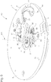
figures 1 à 5 représentent, de façon schématisée et en vue de face, des pièces d'horlogerie incorporant un double affichage selon l'invention ; - les
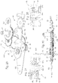
figures 6 à 25 illustrent un premier mode de réalisation : - les
figures 6 ,7 , et13 à 18 représentent, de façon schématisée et en perspective, des vues partielles d'un mécanisme selon l'invention, en suivant la séquence de son assemblage, lesfigures 6 à 15 et18 illustrant plus particulièrement une première commande d'embrayage/débrayage dite aussi marche/arrêt, et lesfigures 16 et17 illustrant une commande de remise à zéro de type retour volant dit fly-back ;
- la
figure 8 représente, de façon schématisée et en perspective, un mobile de fuseau comportant une roue à friction, qu'incorpore le mécanisme selon ce premier mode de réalisation ; - la
figure 10 représente, de façon schématisée, partielle, et en coupe selon un plan passant par l'axe du pivot de seconde du mouvement de base auquel se rapporte le mécanisme selon l'invention, qui est représenté dans une position débrayée de l'affichage secondaire qu'il comporte ; - la
figure 11 représente le mécanisme de lafigure 10 dans une position embrayée de cet affichage secondaire ; - la
figure 12 représente, de façon schématisée, partielle, et en coupe selon un plan passant par l'axe du pivot de seconde, un détail de la coopération entre une bascule de commande chronographe et un coeur de seconde que comporte l'invention, dans la position de lafigure 10 ; - les
figures 19 et 20 représentent, de façon schématisée, partielle et en vue en plan, le mécanisme desfigures 6 à 18 dans, respectivement, une position désarmée et une position armée du fly-back ; - la
figure 21 représente, de façon schématisée, partielle, la chaîne cinématique du mécanisme desfigures 6 à 20 , selon une section en ligne brisée passant par les axes de pivotement des différents mobiles qui y sont représentés ; - les figures 22 et 23 représentent, de façon schématisée et partielle, en plan, en vue respectivement de dessus et de dessous, le mécanisme selon l'invention, dans une position où la couronne du mouvement est enfoncée et où aucune mise à l'heure n'est possible, et où la commande d'embrayage/débrayage est en position embrayée ;
- les figures 24 et 25 représentent, de façon schématisée et partielle, en plan, en vue respectivement de dessus et de dessous, le mécanisme selon l'invention, dans une position où la couronne du mouvement est tirée dans une position où la mise à l'heure de l'affichage secondaire est possible, et où la commande d'embrayage/débrayage est en position débrayée ;
- les
figures 26 à 36 illustrent un deuxième mode de réalisation : - la
figure 26 représente, de façon schématisée et en coupe selon un plan passant par l'axe du pivot de seconde du mouvement de base auquel se rapporte le mécanisme selon l'invention, et par l'axe d'une roue à colonnes que comporte ce mécanisme, un détail de la chaîne cinématique de manoeuvre d'une bascule de commande de chronographe selon ce deuxième mode de réalisation ; - les
figures 27 et 28 représentent, de façon schématisée et en perspective, le mécanisme de lafigure 26 , dans une position d'embrayage d'un mécanisme d'embrayage dit inter-fuseau représenté schématiquement et en coupe sur lafigure 31 ; - les
figures 29 et 30 représentent, de façon schématisée et en perspective, le mécanisme de lafigure 26 , dans une position de débrayage de ce mécanisme inter-fuseau représenté schématiquement et en coupe sur la figure 32 ; - la
figure 33 représente, de façon schématisée et en perspective, le mécanisme desfigures 26 à 32 , avec le mécanisme inter-fuseau engrenant avec un mobile de fuseau que comporte le mécanisme ; - les
figures 33A et33B représentent, en vue de côté, respectivement les positions embrayée et débrayée du mécanisme inter-fuseau ; - la
figure 33C représente, de façon schématisée et similaire à lafigure 21 , la chaîne cinématique du deuxième mode de réalisation ; - la
figure 34 représente, de façon schématisée et en perspective, une vue d'ensemble du même mécanisme, en position d'assemblage intermédiaire sous un pont de l'axe du chronographe ; - la
figure 35 représente, de façon schématisée et en perspective, une vue d'ensemble du même mécanisme, en position d'assemblage intermédiaire avec les chaussées coeurs de minute et d'heure du chronographe, et une bascule de chronographe que comporte un mécanisme de fly-back selon l'invention ; - la
figure 36 représente, de façon schématisée et en perspective, le mécanisme de lafigure 35 , en position d'assemblage avec le mécanisme de fly-back complet.
- the
Figures 1 to 5 represent, schematically and in front view, timepieces incorporating a dual display according to the invention; - the
Figures 6 to 25 illustrate a first embodiment: - the
figures 6 ,7 , and13 to 18 represent schematically and in perspective, partial views of a mechanism according to the invention, by following the sequence of its assembly, theFigures 6 to 15 and18 illustrating more particularly a first clutch / disengagement command also called on / off, and thefigures 16 and17 illustrating a flyback return type command flyback;
- the
figure 8 represents schematically and in perspective, a spindle wheel having a friction wheel, which incorporates the mechanism according to this first embodiment; - the
figure 10 represents, schematically, partially, and in section along a plane passing through the axis of the second pivot of the base movement to which the mechanism according to the invention relates, which is shown in a disengaged position of the secondary display qu 'it comprises ; - the
figure 11 represents the mechanism of thefigure 10 in an engaged position of this secondary display; - the
figure 12 represents, schematically, partially, and in section along a plane passing through the axis of the second pivot, a detail of the cooperation between a chronograph control rocker and a heart of second that includes the invention, in the position of thefigure 10 ; - the
Figures 19 and 20 represent, schematically, partially and in plan view, the mechanism ofFigures 6 to 18 in, respectively, a disarmed position and an armed fly-back position; - the
figure 21 represents, in a schematic, partial way, the kinematic chain of the mechanism ofFigures 6 to 20 , according to a broken line section passing through the pivot axes of the various mobiles represented therein; - FIGS. 22 and 23 are schematically and partially in plan, in a view respectively from above and from below, the mechanism according to the invention, in a position where the crown of the movement is depressed and where no time setting is not possible, and where the clutch / clutch control is in the engaged position;
- FIGS. 24 and 25 show, schematically and partially, in plan, in a view respectively from above and from below, the mechanism according to the invention, in a position where the crown of the movement is pulled into a position where the setting time of the secondary display is possible, and where the clutch / disengage control is in the disengaged position;
- the
Figures 26 to 36 illustrate a second embodiment: - the
figure 26 represents, schematically and in section along a plane passing through the axis of the second pivot of the base movement to which the mechanism according to the invention relates, and by the axis of a column wheel that includes this mechanism, a detail of the kinematic operating chain of a chronograph control lever according to this second embodiment; - the
Figures 27 and 28 represent, schematically and in perspective, the mechanism of thefigure 26 , in a clutch position of an inter-spindle clutch mechanism shown schematically and in section on thefigure 31 ; - the
Figures 29 and 30 represent, schematically and in perspective, the mechanism of thefigure 26 , in a declutching position of this inter-spindle mechanism shown schematically and in section in FIG. 32; - the
figure 33 represents, schematically and in perspective, the mechanism ofFigures 26 to 32 , with the inter-spindle mechanism meshing with a spindle mobile that includes the mechanism; - the
Figures 33A and33B represent, in side view, respectively the engaged and disengaged positions of the inter-spindle mechanism; - the
figure 33C represents, schematically and similar to thefigure 21 the kinematic chain of the second embodiment; - the
figure 34 represents, schematically and in perspective, an overview of the same mechanism, in intermediate assembly position under a bridge of the axis of the chronograph; - the
figure 35 represents, schematically and in perspective, an overview of the same mechanism, in an intermediate assembly position with the chronograph hour and minute heart tracks, and a chronograph scale that includes a fly-back mechanism according to the invention; - the
figure 36 represents, schematically and in perspective, the mechanism of thefigure 35 , in assembly position with the complete fly-back mechanism.
L'invention concerne le domaine des pièces d'horlogerie comportant des affichages multiples. Elle concerne plus particulièrement les pièces d'horlogerie comportant une fonction de chronographe.The invention relates to the field of timepieces with multiple displays. It relates more particularly to timepieces having a chronograph function.
L'invention est conçue pour son adaptation à un mouvement d'horlogerie existant, sur planche ou par module additionnel. Elle peut tout aussi bien être intégrée à un mouvement.The invention is designed for its adaptation to an existing clockwork movement, board or additional module. It can just as easily be part of a movement.
L'invention s'attache à procurer une grande facilité d'utilisation, avec une polyvalence d'un affichage secondaire, avec un nombre de composants réduit, et un faible encombrement en épaisseur.The invention seeks to provide a great ease of use, with a versatility of a secondary display, with a reduced number of components, and a small overall thickness.
L'invention concerne un mécanisme 100 d'affichage additionnel sur demande, constituant au moins un affichage secondaire 2 d'au moins une première grandeur physique, pour un mouvement 6 de mesure ou/et de génération d'au moins une grandeur physique. Ce mouvement 6 comporte un premier affichage 1 d'au moins une grandeur physique.The invention relates to an on-demand
Le mécanisme 100 d'affichage additionnel sur demande comporte :
- un
premier poussoir 4 marche-arrêt agencé pour actionner des moyens de commande de premiers moyens d'embrayage/débrayage agencés pour autoriser ou interdire l'embrayage d'au moins un indicateur d'affichage de cet affichagesecondaire 2 avec le mouvement 6. Cepremier poussoir 4 peut consister en un poussoir que comporte le mouvement 6. un deuxième poussoir 5 agencé pour actionner des moyens de commande de remise à zéro de cet affichagesecondaire 2.Ce deuxième poussoir 5 peut consister en un poussoir que comporte le mouvement 6.
- a first push-
button 4 on-off arranged to actuate means for controlling first clutch / disengagement means arranged to allow or prohibit the clutch of at least one display indicator of thissecondary display 2 with themovement 6. Thisfirst pusher 4 may consist of a pusher that comprises themovement 6. - a
second pusher 5 arranged to actuate reset control means of thissecondary display 2. Thissecond pusher 5 may consist of a pusher that comprises themovement 6.
Selon l'invention :
cet affichage secondaire 2 comporte, pour l'entraînement d'un indicateur d'affichage de la première grandeur physique, une chaussée-coeur de premièregrandeur physique 36 sans denture, mobile en pivotement autour d'un axe de pivotement. Cette chaussée-coeur 36 comporte un coeur périphérique 42 agencé pour coopérer avec un marteau que comporte le mécanisme 100 pour la remise ducoeur 42 dans une position d'origine.- les premiers moyens de commande d'embrayage/débrayage commandent l'embrayage, respectivement le débrayage, de cette chaussée-coeur de première
grandeur physique 36 parrapport au mouvement 6 ; - le deuxième poussoir 5 commande la remise à zéro de cet affichage
secondaire 2 par, d'une part une commande de débrayage de ces premiers moyens de commande d'embrayage-débrayage, et d'autre part par une commande d'indexation en position d'origine ducoeur 42 de la chaussée-coeur de premièregrandeur physique 36.
- this
secondary display 2 comprises, for driving a display indicator of the first physical quantity, a ground-core of firstphysical magnitude 36 without teeth, movable pivotally about a pivot axis. This ground-core 36 comprises aperipheral core 42 arranged to cooperate with a hammer that includes themechanism 100 for the delivery of theheart 42 in an original position. - the first clutch / disengagement control means controls the clutch, respectively the disengagement, of this road-heart of first
physical magnitude 36 with respect to themovement 6; - the
second pusher 5 controls the reset of thissecondary display 2 by, on the one hand a disengagement command of these first clutch-disengagement control means, and on the other hand by an indexing control in position d origin of theheart 42 of the road-heart of firstphysical size 36.
De préférence, le mécanisme 100 constitue un affichage additionnel de plusieurs grandeurs physiques, et :
cet affichage secondaire 2 comporte, pour l'entraînement d'indicateurs d'affichage de la première grandeur physique, et d'indicateurs d'affichage d'au moins d'une deuxième grandeur physique ou/et d'une troisième grandeur physique, respectivement cette chaussée-coeur de premièregrandeur physique 36, et au moins une chaussée-coeur de deuxièmegrandeur physique 70, ou/et une chaussée-coeur de troisièmegrandeur physique 80 qui sont mobiles en pivotement indépendamment l'une de l'autre, et qui comportent respectivement des coeurs périphériques 42, 72, 82. Ces derniers sont agencés pour coopérer chacun avec un marteau que comporte le mécanisme 100 pour la remise du coeur concerné dans une position d'origine.- le
premier poussoir 4 marche-arrêt commande des deuxièmes moyens de commande d'embrayage/débrayage, qui sont agencés pour autoriser ou interdire l'embrayage avec le mouvement 6, d'au moins la chaussée-coeur de deuxièmegrandeur physique 70 ou/et la chaussée-coeur de troisièmegrandeur physique 80; - le deuxième poussoir 5 commande la remise à zéro de l'affichage
secondaire 2 par, d'une part une commande de débrayage de ces deuxièmes moyens de commande d'embrayage-débrayage, et d'autre part une commande d'indexation en position d'origine deces coeurs
- this
secondary display 2 comprises, for driving display indicators of the first physical quantity, and display indicators of at least a second physical quantity or / and a third physical quantity, respectively this physical first-magnitude ground-core 36, and at least one second physical-size ground-core 70, or / and a third-physical-size ground-core 80 which are pivotally movable independently of each other, and which respectively compriseperipheral cores mechanism 100 for the delivery of the heart concerned in an original position. - the
first pushbutton 4 on-off controls the second clutch / clutch control means, which are arranged to allow or prohibit the clutch with themovement 6, at least the floor-heart of secondphysical magnitude 70 and / or the ground-heart of thirdphysical size 80; - the
second pusher 5 controls the reset of thesecondary display 2 by, on the one hand, a disengagement command of these second clutch-disengagement control means, and on the other hand an indexing control in position d origin of thesehearts
Dans une réalisation préférée, qui sera décrite ci-après plus en détail, l'invention concerne notamment un mécanisme 100 de double affichage pour pièce d'horlogerie 1000 avec un mouvement 6, notamment un seul mouvement 6, le premier affichage 1, dit aussi affichage principal, étant l'affichage en mode normal de l'heure et en continu, l'affichage secondaire 2 étant un affichage additionnel.In a preferred embodiment, which will be described hereinafter in more detail, the invention relates in particular to a
L'affichage secondaire 2 additionnel peut consister en un affichage de l'heure, un affichage de fuseau horaire, un timer ou programmateur ou minuteur, un chronographe, ou autre. L'utilisateur a le choix de son application.The additional
L'affichage secondaire 2 est modifiable à tout instant, et peut être découplé à volonté du premier affichage 1, et est réglable indépendamment du premier affichage 1.The
Dans une application particulière et préférée de l'invention, l'affichage secondaire 2 est lié à une fonction de chronographe. Dans une application particulière de l'invention, ce chronographe est couplé avec une mise à l'heure continue par une couronne 3. Selon une caractéristique propre à l'invention, l'affichage secondaire 2 est manipulable pendant la marche du chronographe.In a particular and preferred application of the invention, the
De façon préférée, la mise à l'heure sur le premier affichage 1 ou/et et l'affichage secondaire 2 est réalisée, au choix de l'utilisateur, de façon indépendante ou simultanée, par sélection d'une position différente de traction de la couronne 3.Preferably, the setting time on the
La pièce d'horlogerie 1000, ou le mécanisme 100, ou le mécanisme additionnel, comporte un premier poussoir 4 de fonction marche-arrêt pour la mise en marche, ou l'arrêt, de l'affichage secondaire 2, fonctionnel quand la couronne 3 est poussée. Dans le cas de la fonction chronographe, cette marche-arrêt concerne les trois aiguilles, heures, minutes et secondes de l'affichage secondaire 2. Ce premier poussoir 4 peut être activé à tout moment.The
Un deuxième poussoir 5 est utilisé pour une fonction « retour en vol », dite ci-après « fly-back », de réinitialisation ou remise à zéro de l'affichage secondaire 2, au niveau de la totalité des afficheurs que comporte cet affichage secondaire 2, en particulier, tel que décrit ci-après, de ses aiguilles d'heures, minutes et secondes. Si cette manipulation est effectuée avec le chronographe en marche, les trois aiguilles repartent dès qu'on lâche le deuxième poussoir 5. Si cette manipulation est effectuée avec le chronographe à l'arrêt, les trois aiguilles restent à zéro. Ce deuxième poussoir 5 peut être activé à tout moment, et est fonctionnel quelque soit la position de la couronne 3.A
A tout moment on peut effectuer des manipulations de la couronne 3, mais elles n'interrompent pas l'affichage secondaire 2.At any time it is possible to manipulate the
La couronne 3 comporte plusieurs positions de traction. On appellera T1 la position de couronne poussée au fond, T2 la position intermédiaire servant aux corrections de l'affichage secondaire 2, et T3 la position de couronne entièrement tirée dehors pour la mise à l'heure simultanée du premier affichage 1 et de l'affichage secondaire 2. Dans le présent cas, on corrige en T2 l'affichage additionnel, donc l'affichage secondaire 2.The
Une première position T2 de traction intermédiaire permet la mise à l'heure de l'affichage secondaire 2, au niveau des heures et minutes, dans les deux sens, sans pour autant modifier le premier affichage 1. La seconde de l'affichage secondaire 2 reste, pendant cette manipulation, là où on l'a arrêtée en tirant la couronne 3, si le chronographe est arrêté ; dans le cas contraire cette seconde continue de tourner. Il en est de même dans la position T3 de traction de la couronne 3, sauf si le mouvement est muni d'un système de frein dit stop secondes, ce qui n'est pas le cas du dispositif présenté dans la présente description, un tel système de frein dit stop secondes ne présentant pas d'avantage particulier dans le cas d'espèce, mais plutôt une complexité et un encombrement inutiles.A first intermediate traction position T2 makes it possible to set the
Une position de traction complète T3 permet la correction simultanée du premier affichage 1 et de l'affichage secondaire 2, au niveau des heures et minutes, simultanément et dans les deux sens.A complete pulling position T3 allows the simultaneous correction of the
Un important avantage de l'invention est de permettre l'utilisation d'un mouvement 6 existant.An important advantage of the invention is to allow the use of an existing
En effet, le mécanisme de double affichage 100 ne consomme que très peu d'énergie, correspondant uniquement aux frottements induits par les mobiles supplémentaires par rapport au mouvement de base.Indeed, the
Différentes options peuvent être combinées, tel que visible sur les
Il est aussi possible de positionner un dispositif de correction de date sous corne, pour prévenir toute fausse manipulation.It is also possible to position a date correction device under horn, to prevent mishandling.
Le réglage des affichages, notamment de l'affichage secondaire 2, doit pouvoir se faire dans les deux sens, en particulier pour la fonction timer.The setting of the displays, in particular of the
La réalisation de l'invention est décrite ici de façon non limitative sur la base d'un mouvement 6 existant. La présente description concerne l'exemple de l'adaptation sur un mouvement « ETA 2892 ». L'adaptation se fait de préférence par la mise en place d'un étage supplémentaire 7, de préférence supporté par une plaque support additionnelle 8.The embodiment of the invention is described here without limitation on the basis of an existing
Les
Selon l'invention, dans ce premier mode, les deuxièmes moyens de commande d'embrayage/débrayage comportent un mobile de fuseau 20 mobile en pivotement et qui comporte, coaxiales et agencées pour coopérer l'une avec l'autre par une liaison à friction, une roue à friction 21 engrenant directement avec ledit mouvement 6 d'une part, et une roue de fuseau 25 d'autre part. Cette roue de fuseau 25 est agencée pour entraîner, en position d'embrayage du mobile de fuseau 20, directement ou indirectement, au moins la chaussée-coeur de deuxième grandeur physique 70, ou/et la chaussée-coeur de troisième grandeur physique 80.According to the invention, in this first mode, the second clutch / clutch control means comprise a spindle mobile 20 pivotally movable and which comprises, coaxial and arranged to cooperate with each other. the other by a friction link, a
Tel que visible sur la
Le mouvement 6 comporte une roue des heures 12, réglable par une minuterie 13, de préférence décentrée, qui engrène, au travers d'un rouage intermédiaire 14, avec une roue de minute 15 qui fait un tour en une heure. La roue des heures 12 est maintenue sur la platine du mouvement 6 par une plaquette 12A.The
Cette roue de minute 15 engrène avec un étage de réduction, sous la forme d'un intermédiaire réducteur 16 comportant deux étages 17 et 18, visible sur la
Selon l'invention, cette roue à friction 21 prend appui, par un mécanisme de friction sous forme de pince 22 et/ou d'une surface de friction, sur l'axe inférieur 26 du mobile de fuseau 20 et/ou sur une surface inférieure 24 que comporte la roue de fuseau 25 en position médiane du mobile de fuseau 20. Le mobile de friction constitué par la roue de friction 21 et la roue de fuseau 25 a pour fonction de permettre le découplage de la roue de fuseau 25 de la roue de friction 21, de façon à constituer une chaussée additionnelle que l'on peut découpler pour manipuler seulement l'affichage secondaire 2, la friction étant commandée par un renvoi intermédiaire 62 qui engrène avec la roue de fuseau 25, et qui est lui-même commandé ou non par un pignon d'extension de mise à l'heure 11 prolongeant un pignon de mise à l'heure 9 que comporte le mouvement 6.According to the invention, this
Le mobile de fuseau 20 est un mobile étagé d'axe 20A, tel que visible sur la
Le mobile de friction a pour fonction de permettre le découplage de la roue de fuseau 25 de la roue de friction 21, c'est une chaussée additionnelle que l'on peut découpler pour manipuler seulement l'affichage secondaire 2. La friction est commandée par un renvoi intermédiaire 62 qui engrène avec la roue de fuseau 25, et qui est lui-même commandé ou non par le pignon d'extension de mise à l'heure 11, tel que visible sur la
Le pivot de seconde 30 du mouvement de base 6 est coaxial à la roue de minute 15, tel que visible sur la
La
Selon l'invention, les premiers moyens d'embrayage/débrayage sont constitués par la combinaison, d'une part d'un alésage conique 41, respectivement un cône, que comporte, selon son axe de pivotement, la chaussée-coeur de première grandeur physique 36, et d'autre part d'un cône 49, respectivement un alésage conique, que comporte le mouvement 6, ou qui est raccordé à ce dernier. Cette disposition s'applique aussi bien au présent premier mode qu'au deuxième mode de réalisation présenté plus loin, ou à d'autres modes encore de réalisation.According to the invention, the first clutch / disengagement means consist of the combination, on the one hand of a
Plus particulièrement dans cette application où la chaussée-coeur de première grandeur physique 36 est une chaussée-coeur de seconde, du côté inférieur, cette chaussée-coeur de seconde 36 comporte, selon son axe de pivotement, un alésage conique 41, qui est agencé pour coopérer avec une portée conique 49 que comporte le pivot de seconde 30 du mouvement 6. L'homme du métier saura comment réaliser la configuration inverse en permutant cône et alésage conique.More particularly in this application where the road-core of first
Entre la tige 37 et l'alésage conique 41, la chaussée-coeur de seconde 36 se déploie sous forme d'un flasque dont le contour périphérique constitue une came 42 sous la forme d'un coeur d'horlogerie traditionnel, agencé pour coopérer avec un marteau pour sa remise dans une position d'origine. Ce flasque comporte à sa partie inférieure, c'est-à-dire du côté de l'alésage conique 41, une surface d'appui constituée par un renflement ou encore une rampe rayonnée 43, qui est agencée pour coopérer avec une surface d'appui complémentaire telle qu'un chanfrein 44 que comporte le bord de la lumière 31 de la bascule 32, pour, lors d'un mouvement de pivotement plan de cette bascule 32, rapprocher ou éloigner une surface supérieure 45 que comporte le flasque du coeur 36 d'une part, d'une surface inférieure 46 que comporte le pont de guidage 39 d'autre part, tel que visible sur les
La chaussée-coeur de seconde 36 comporte encore, à sa partie supérieure du côté de sa tige 37, un logement 47 qui est agencé pour recevoir une première extrémité d'un ressort de rappel 48, dont l'autre extrémité est en appui sur la surface inférieure 46 du pont de guidage 39.The second core-
Quand le chronographe est à l'arrêt, la surface inférieure 46 du pont de guidage 39 et la surface supérieure 45 du coeur 36 sont en contact, tandis que l'alésage conique 41 est distant du cône 49 du pivot de seconde 30 du mouvement 6, d'un écart E.When the chronograph is stopped, the
Quand le chronographe est en marche, le ressort 48 inséré entre le pont de guidage 39 et le coeur 36 plaque ces surfaces coniques 41 et 49 en contact l'une contre l'autre, réalisant un couplage complet, tandis que la surface supérieure 45 du flasque de la chaussée-coeur de seconde 36 est éloignée de la surface inférieure 46 du pont de guidage 39.When the chronograph is running, the
Pour amener la bascule 32 dans une position poussée, où le chanfrein 44 de sa lumière 31 pousse la rampe 42 du coeur 36, tel que visible sur la
Tel que visible sur les
La
Lors de l'action suivante de l'utilisateur sur le premier poussoir 4, il immobilise la roue dentée supérieure 51 dans une nouvelle position angulaire, la roue dentée inférieure 52 occupe aussi une nouvelle position angulaire où deux dents 52A et 52C bloquent la première surface d'appui 56, dans une position où le premier baladeur 54 est écarté de l'axe de pivot de seconde 30A, et où la bascule 32 de commande du chronographe est dégagée du coeur 36, qui est ainsi débrayé du pivot de seconde 30 du mouvement 6. Le ressort 48 tend à repousser en permanence le coeur 36 du pivot 30, ce qui assure un découplage instantané. La deuxième surface d'appui 57 du premier baladeur 54 vient quant à elle en appui sur un chant 58 de la bascule 32 pour commander le pivotement de cette dernière.During the next action of the user on the
En somme, le premier baladeur 54 effectue un mouvement alternatif lors de chaque action sur le premier poussoir 4. Dans une variante particulière, le chant 58 comporte un creux 58A, ou un cran, ou un vé, ou similaire, pour maintenir la deuxième surface d'appui 57 du baladeur 54 dans une position stable.In sum, the
Ce premier baladeur 54 coopère encore, tel que visible sur la
De façon avantageuse et propre à l'invention, le premier poussoir 4 et le deuxième poussoir 5 sont indépendants, et la fonction de l'un peut intervenir à tout moment en prenant la priorité sur l'autre.Advantageously and according to the invention, the
La
De façon propre à l'invention, la bascule d'arrêt 32 est rappelée vers le baladeur 54 par un ressort de bascule 34, et comporte un cran de bascule 86 qui est agencé pour entraîner un axe 66. Cet axe 66 supporte un mobile intermédiaire de minute 90 libre en pivotement autour de l'axe 66, pour son engrènement avec la chaussée-coeur de minute 76, quand les premiers moyens de commande d'embrayage/débrayage sont en position d'embrayage.In a manner peculiar to the invention, the
Afin de permettre le déclenchement du pivotement de la bascule de chronographe 65 dans le trou oblong 61, le cran 86, visible sur les
Quand l'action suivante sur le premier poussoir 4 éloigne le premier baladeur 54 de l'axe 30A du pivot de seconde, la bascule 32 est dégagée du coeur 36, et reste bloquée dans cette position par le premier baladeur 54, la roue dentée inférieure 32 et le sautoir 53. Le ressort de rappel 64 éloigne alors l'axe 66 de l'axe 30A du pivot de seconde, et dégrène les roues 68 et 76 respectivement des chaussées-coeur 70 et 80.When the following action on the
La couronne 3 est agencée pour occuper, sur action de l'utilisateur, une position T3 de réglage de l'affichage secondaire 2, dans laquelle la roue de fuseau 25 coopère, au travers d'un mobile intermédiaire de minuterie 62, avec la minuterie 13.The
Dans une position tirée de la couronne 3, on entraîne le renvoi de mise à l'heure 11, et, par un mobile intermédiaire 62, la roue à friction 21. Dans cette position T3, le pignon coulant du mouvement manipule, par le biais du renvoi inférieur 9, la roue de minuterie du mouvement, et, par conséquent, le premier affichage 1 principal. En même temps, par le biais du renvoi supérieur 11, le pignon coulant du mouvement manipule ce pignon intermédiaire 62, et donc la roue de fuseau 25.In a position taken from the
Dans une réalisation préférée, tel que visible sur les figures, la chaussée-coeur de première grandeur physique 36, et au moins une chaussée-coeur de deuxième grandeur physique 70, ou/et une chaussée-coeur de troisième grandeur physique 80, sont montées coaxiales à une prise de mouvement directement raccordée au mouvement 6 ou que comporte ce mouvement 6.In a preferred embodiment, as shown in the figures, the first-magnitude physical-core-
Dans la réalisation ici décrite en détail, la chaussée-coeur de deuxième grandeur physique 70 est une chaussée-coeur de minute, et la chaussée-coeur de troisième grandeur physique 80 est une chaussée-coeur d'heure.In the embodiment here described in detail, the second-magnitude physical-gravity pavement-
Ces dispositions s'appliquent aussi bien au présent premier mode qu'au deuxième mode de réalisation présenté plus loin, ou à d'autres modes encore de réalisationThese provisions apply as well to the present first mode as to the second embodiment presented below, or to other modes of embodiment.
Tel que visible sur les
Cette chaussée-coeur des minutes 70 est, tel que visible sur les
On comprend que, si la chaussée-coeur de seconde 36 n'a pas besoin de denture pour son entraînement, qui est réalisé par l'emmanchement conique sur le pivot de seconde 30 du mouvement 6, en revanche les chaussées-coeur 70 et 80 nécessitent ces dentures 72 et 82 pour leur entraînement en pivotement.It is understood that, if the second core-
Pour le maintien en position des chaussées-coeur 36, 70 et 80, lors de l'arrêt de l'affichage secondaire central 2, par nouvelle pression du premier poussoir 4, le mécanisme 100 comporte avantageusement des moyens de friction, non représentés sur les figues, tels que clinquant ou similaire.For maintaining the position of the sheaves-
De façon préférée, le deuxième poussoir 5 commande, quand il est enfoncé, le mouvement d'une bascule de fly-back 60, pour prendre appui sur les coeurs 42, 72, 82, pour les ramener dans une position d'origine. La
La bascule de fly-back 60 comporte encore le pion 59 qui vient en interaction avec le premier baladeur 54, tel que visible sur la
Si on actionne le deuxième poussoir 5, on fait pivoter la bascule de fly-back 60, et on tend à pousser, par ce pion 59, le premier baladeur 54 pour le contraindre à pivoter, et on déclenche alors l'arrêt du chronographe s'il était en marche. A l'inverse, si on actionne le premier poussoir 4 pour mettre en marche le chronographe, on repousse le pion 59, et donc la bascule de fly-back 60 : chaque manipulation tend à annuler l'autre.If the
L'axe 66 est disposé à une extrémité opposée au pivot de la bascule de chronographe 65, lequel pivot est coaxial avec l'axe 20A de pivotement du mobile de fuseau 20. Cet axe 66 est mobile dans le trou oblong 61, selon la position angulaire de la bascule de chronographe 65, et il porte une roue dentée d'entraînement de minute chronographe 68 qui, selon la position du baladeur, engrène ou non avec la denture 72 de la chaussée-coeur de minute 70. Cette roue dentée 68 est libre, entraînée par le mobile de fuseau 20, et effectue un tour par heure. Elle a le même nombre de dents que la denture 72 de la chaussée-coeur de minute 70, cette dernière effectue donc aussi, quand elle est entraînée, un tour par heure.The
Quand la position éloignée du deuxième baladeur empêche tout transfert de couple vers les chaussées-coeurs de minute 70 et d'heure 80, les aiguilles de minute et d'heure respectivement liées à ces dernières chaussées ne sont pas entraînées, car rien ne les touche : le pivotement du coeur 36 de seconde se fait par simple guidage dans l'alésage 74 de la chaussée-coeur de minute 70, sans aucun effet d'entraînement, et il en est a fortiori de même pour la chaussée-coeur 80 d'heure. Si en revanche la seconde marche, les autres aiguilles marchent aussi, car elles sont toutes les trois sous l'emprise de la bascule de commande du chronographe 32.When the distant position of the second player prevents any transfer of torque to the heart-roads of
Tel que visible sur la
C'est la roue à friction 21, qui tourne en permanence à raison de un tour par heure, qui permet d'assurer l'entraînement en transmettant le couple issu du mouvement 6 de base. Comme elle est à friction, tout en tournant elle peut être découplée ou non de la roue de fuseau 25 du mobile de fuseau 20. En somme, cette roue à friction 21 assure, quand la friction se fait, la totalité de l'entraînement de l'affichage secondaire 2.It is the
De préférence, le deuxième poussoir 5 de remise à zéro entraîne une bascule de fly-back 60, pour prendre appui sur la chaussée-coeur de seconde 36 et sur la chaussée-coeur de minute 72 pour les ramener dans une position d'origine. Un ressort de fly-back 77 est agencé pour coopérer ou non, au niveau d'un cran 79 que comporte le ressort 77, avec un pion 78 que comporte la bascule de fly-back 60. Le ressort 77 tend à exercer sur la bascule de fly-back 60, par l'intermédiaire du pion 78, un effort dans le sens de la flèche F' de la
Un autre ressort de rappel 85 tend à rappeler le deuxième poussoir 5 vers l'extérieur. Quand on appuie sur le deuxième poussoir 5, on doit vaincre l'effort résistant du ressort de fly-back 77, ce qui permet de passer de la position représentée en
En position de marche du chronographe, le baladeur 54 est au repos au fond de la roue à colonne 50 et sur le pion 59 de la bascule de fly-back 60. Dans le cas où l'utilisateur arriverait à déclencher simultanément les deux poussoirs 4 et 5, l'appui sur les deux poussoirs 4 et 5 provoque la même réaction de faire pivoter le baladeur 54 et arrêter la fonction chronographe.In the running position of the chronograph, the
Par contre, si le chronographe est arrêté, l'appui du deuxième poussoir 5 ne fait que remettre les coeurs à zéro, car sa course est limitée en sorte que le pion 59 ne puisse pas faire plus que rejoindre le baladeur 54 et ne pas le pousser plus loin que la roue à colonne 50 ne l'a fait. Si en même temps intervient un appui sur le premier poussoir 4, il n'aura de conséquence que de provoquer, après le relâchement du deuxième poussoir 5, la mise en fonction du chronographe. Donc, même si l'utilisateur parvenait à déclencher simultanément les deux poussoirs 4 et 5, ce qui est plus que difficile, il ne casserait rien car les deux fonctions peuvent parfaitement coexister.On the other hand, if the chronograph is stopped, the support of the second push-
Pour résumer le fonctionnement du mécanisme 100 dans ce premier mode de réalisation, on trouvera ci-après les conséquences sur l'affichage des différentes actions sur la couronne 3 et sur le premier poussoir 4 et sur le deuxième poussoir 5 :
T1 couronne 3 enfoncée, premier poussoir 4 M/A (marche/arrêt) en position marche, absence d'action sur deuxième poussoir 5: chronographe activé ;T1 couronne 3 enfoncée, premier poussoir 4 M/A en position marche,poussoir 5 actionné et relâché : remise à zéro affichagesecondaire 2 et re-départ immédiat du chronographe. Le fly-back a une fonction instantanée, il ne peut pas rester enfoncé, il revient immédiatement à sa position extérieure ;T1 couronne 3 enfoncée, premier poussoir 4 M/A en position marche,poussoir 5 maintenu enfoncé : remise à zéro affichagesecondaire 2 et.affichage secondaire 2 stoppé.T1 couronne 3 enfoncée, premier poussoir 4 M/A en position arrêt, absence d'action sur deuxième poussoir 5 :affichage secondaire 2 relâché, les trois aiguilles restent dans la position dans laquelle ont été découplées par lepremier poussoir 4 ;T1 couronne 3 enfoncée, premier poussoir 4 M/A en position arrêt, deuxième poussoir 5 actionné et relâché: remise à zéro affichagesecondaire 2. Le fly-back relâché, les trois aiguilles de l'affichagesecondaire 2 se remettent à zéro et elles y restent ;T1 couronne 3 enfoncée, premier poussoir 4 M/A en position arrêt,poussoir 5 maintenu enfoncé: remise à zéro affichagesecondaire 2 et.affichage secondaire 2 stoppé.- en position T1 aucune mise à l'heure n'est possible, ni sur le
premier affichage 1, ni sur le deuxième affichage 2. - T2 première traction intermédiaire, premier poussoir 4 M/A en position marche, absence d'action sur deuxième poussoir 5 : découplage des affichages 1
et 2, ce découplage n'est pas donné par la couronne, mais provient de l'action du poussoir.L'affichage secondaire 2 continue de fonctionner et il n'y a pas de possibilité de le manipuler.L'affichage principal 1 n'est pas affecté ; - T2 première traction intermédiaire, premier poussoir 4 M/A en position marche, deuxième poussoir 5 actionné puis relâché: découplage des affichages 1
et 2, ce découplage n'est pas donné par la couronne, mais provient de l'action du poussoir.L'affichage secondaire 2 continue de fonctionner et on peut le manipuler.L'affichage principal 1 n'est pas affecté; - T2 première traction intermédiaire, premier poussoir 4 M/A en position marche, deuxième poussoir 5 maintenu enfoncé: l'affichage
secondaire 2 est stoppé et il n'y a plus possibilité de le manipuler.L'affichage principal 1 n'est pas affecté ; - T2 première traction intermédiaire, premier poussoir 4 M/A en position arrêt, absence d'action sur deuxième poussoir 5: découplage des affichages 1
et 2. On peut le manipuler l'affichagesecondaire 2 pour la mise à l'heure.L'affichage principal 1 n'est pas affecté; - T2 première traction intermédiaire, premier poussoir 4 M/A en position arrêt, deuxième poussoir 5 actionné puis relâché: découplage des affichages 1
et 2. Remise à zéro de l'affichagesecondaire 2.L'affichage secondaire 2 cesse de fonctionner. On ne peut pas le manipuler pour la mise à l'heure.L'affichage principal 1 n'est pas affecté; - T2 première traction intermédiaire, premier poussoir 4 M/A en position arrêt, deuxième poussoir 5 maintenu enfoncé découplage des affichages 1
et 2. Remise à zéro de l'affichagesecondaire 2.L'affichage secondaire 2 est stoppé. On ne peut pas le manipuler pour la mise à l'heure.L'affichage principal 1 n'est pas affecté; - T3 traction complète, premier poussoir 4 M/A en position marche, absence d'action sur deuxième poussoir 5:
affichages 1et 2 couplés. Possibilité de manipulation des deux affichages 1et 2 en même temps; - T3 traction complète, premier poussoir 4 M/A en position marche, deuxième poussoir 5 actionné et relâché: remise à zéro de l'affichage
secondaire 2. Possibilité de manipulation des deux affichages 1et 2 en même temps;- T3 traction complète, premier poussoir 4 M/A en position marche, deuxième poussoir 5 maintenu enfoncé:
affichages 1et 2 couplés. Remise à zéro de l'affichagesecondaire 2.L'affichage secondaire 2 cesse de fonctionner. Possibilité de manipulation de l'affichageprincipal excentré 1 seul; - T3 traction complète, premier poussoir 4 M/A en position arrêt, absence d'action sur deuxième poussoir 5:
affichages 1et 2 couplés. Possibilité de manipulation des deux affichages 1et 2 en même temps ; - T3 traction complète, premier poussoir 4 M/A en position arrêt, deuxième poussoir 5 actionné et relâché: remise à zéro de l'affichage
secondaire 2. Possibilité de manipulation des deux affichages 1et 2 en même temps; - T3 traction complète, premier poussoir 4 M/A en position arrêt, deuxième poussoir 5 maintenu enfoncé:
affichages 1et 2 séparés. Remise à zéro de l'affichagesecondaire 2. Possibilité de manipulation de l'affichageprincipal excentré 1 seul.
- T3 traction complète, premier poussoir 4 M/A en position marche, deuxième poussoir 5 maintenu enfoncé:
-
T1 crown 3 depressed, first push 4 M / A (on / off) in on position, no action on second pushbutton 5: chronograph activated; -
T1 crown 3 pressed, first pushbutton 4 M / A in the on position,pushbutton 5 actuated and released: resetsecondary display 2 and immediate restart of the chronograph. The flyback has an instant function, it can not remain depressed, it immediately returns to its external position; -
T1 crown 3 pressed, first push button 4 M / A in the on position,push button 5 held down: resetsecondary display 2 and.secondary display 2 stopped. -
T1 crown 3 pressed, first pusher 4 M / A in the off position, no action on second pusher 5:secondary display 2 released, the three hands remain in the position in which were decoupled by thefirst pusher 4; -
T1 crown 3 pressed, first pushbutton 4 M / A in the off position,second pushbutton 5 pressed and released: resetsecondary display 2. The flyback released, the three hands of thesecondary display 2 are reset to zero and stay there; -
T1 crown 3 pressed, first pushbutton 4 M / A in the off position,pushbutton 5 held down: resetsecondary display 2 and.secondary display 2 stopped. - in position T1 no time setting is possible, neither on the
first display 1 nor on thesecond display 2. - T2 first intermediate traction, first pusher 4 M / A in the on position, no action on second pusher 5: decoupling of
displays secondary display 2 continues to operate and there is no possibility to manipulate it.Main display 1 is not affected; - T2 first intermediate traction, first push 4 M / A in the ON position,
second pushbutton 5 actuated and released: decoupling displays 1 and 2, this decoupling is not given by the crown, but comes from the action of the push.Secondary display 2 continues operate and can be manipulated.Main display 1 is not affected; - T2 first intermediate traction, first push 4 M / A in the ON position,
second push button 5 held down: thesecondary display 2 is stopped and there is no longer any possibility of handling it.Main display 1 is not affected; - T2 first intermediate traction, first pusher 4 M / A in the off position, no action on second pusher 5: decoupling of the
displays secondary display 2 for setting the time.Main display 1 is not affected; - T2 first intermediate traction, first pushbutton 4 M / A in the off position,
second pushbutton 5 actuated and then released: decoupling of thedisplays secondary display 2. Thesecondary display 2 stops working. We can not manipulate it for setting the time.Main display 1 is not affected; - T2 first intermediate traction, first pushbutton 4 M / A in the off position,
second pushbutton 5 held down uncoupling of thedisplays secondary display 2. Thesecondary display 2 is stopped. We can not manipulate it for setting the time.Main display 1 is not affected; - T3 complete traction, first push 4 M / A in on position, no action on second pushbutton 5:
displays displays - T3 complete traction, first push button 4 M / A in the on position,
second push button 5 pressed and released: reset of thesecondary display 2. Possibility of handling bothdisplays - T3 complete traction, first push button 4 M / A in on position,
second push button 5 held down:displays secondary display 2. Thesecondary display 2 stops working. Possibility of manipulation of the eccentricmain display 1 only; - T3 complete traction, first push 4 M / A in the off position, no action on second pushbutton 5:
displays displays - T3 complete traction, first pushbutton 4 M / A in the off position,
second pushbutton 5 pressed and released: reset of thesecondary display 2. Possibility of handling bothdisplays - T3 complete pull, first push 4 M / A in off position,
second push 5 held down:displays secondary display 2. Possibility of manipulation of the maineccentric display 1 only.
- T3 complete traction, first push button 4 M / A in on position,
Les
Ce deuxième mode a pour objet, outre une simplification du mécanisme, d'assurer la séparation complète des fonctions des deux poussoirs: premier poussoir 4 de marche/arrêt et deuxième poussoir 5 de remise à zéro.This second mode aims, in addition to a simplification of the mechanism, to ensure complete separation of the functions of the two pushers:
Il s'agit, ainsi, de rendre la commande de fly-back possible à tout moment. Pour ce faire, il est nécessaire de déconnecter l'engrenage de chronographe des roues centrales. A cet effet, ce deuxième mode de réalisation met en oeuvre une bascule de commande du chronographe 132, qui est particulière, et agencée pour se soulever, et déconnecter facilement l'engrenage sans effort.This is to make the fly-back order possible at any time. To do this, it is necessary to disconnect the chronograph gear from the center wheels. For this purpose, this second embodiment implements a
A cet effet, selon l'invention, les deuxièmes moyens de commande d'embrayage/débrayage comportent un mécanisme inter-fuseau 93 porté par une bascule de commande 132 que comportent les moyens de commande de premiers moyens d'embrayage/débrayage. Ce mécanisme inter-fuseau 93 est un mécanisme d'embrayage, et comporte une roue inférieure 98 engrenant directement avec le mouvement 6 d'une part, et une roue supérieure 96 d'autre part. Cette roue supérieure 96 est agencée pour entraîner, en position d'embrayage du mécanisme inter-fuseau 93, directement ou indirectement, au moins la chaussée-coeur de deuxième grandeur physique 70, ou/et la chaussée-coeur de troisième grandeur physique 80.For this purpose, according to the invention, the second clutch / disengagement control means comprise an
Le mécanisme constitué du premier poussoir 4, de la roue à colonnes 50, et du sautoir 53 est conservé. Mais, tel que visible sur la
Cette bascule de commande du chronographe 132 comporte un chant penté 232, qui est agencé pour faire face au chant chanfreiné 254 du premier baladeur 154. Le mouvement de pivotement du premier baladeur 154 entraîne alors, non seulement un pivotement autour de l'axe 30A du pivot de seconde, mais aussi un mouvement de translation de la bascule de commande du chronographe 132 parallèlement à cet axe 30A du pivot de seconde, de façon ascendante ou descendante selon le sens de pivotement du premier baladeur 154.This
Les
La bascule de commande du chronographe 132 est porteuse du mécanisme inter-fuseau 93. Ce mécanisme inter-fuseau 93 est un mécanisme d'embrayage, en particulier d'embrayage conique dans l'exemple préféré représenté sur les figures, et comporte, tel que visible sur les
Ce moyeu 97 comporte une pente 97A, qui est agencée pour coopérer avec une pente complémentaire 96A que comporte la roue supérieure 96, dans une position d'embrayage représentée à la
Cette position d'embrayage est représentée sur les
La figure 32 illustre la position débrayée de ce mécanisme inter-fuseau 93. Les
On peut voir sur la
Dans ce deuxième mode de réalisation, le mobile de fuseau ne comporte plus de roue à friction, puisque la fonction d'embrayage est remplie par le mécanisme inter-fuseau 93.In this second embodiment, the spindle mobile no longer has a friction wheel, since the clutch function is filled by the
Pour le maintien en position des chaussées-coeur 36, 70 et 80, lors de l'arrêt de l'affichage secondaire central 2, par nouvelle pression du premier poussoir 4, le mécanisme 100 utilise ce mécanisme d'inter-fuseau 93, et plus particulièrement la friction de son ressort 95: le ressort 95 pousse la roue supérieure 96 vers le flasque 94, le frottement contre le flasque génère une friction suffisante pour immobiliser les chaussées-coeur, tout en étant suffisamment réduit pour être vaincu par toute manipulation de la couronne 3.In order to maintain the position of the
La
La
La bascule de chronographe 165 comporte encore, à une deuxième extrémité opposée à la première, une face d'appui 365 agencée pour coopérer en butée avec une goupille 208, que porte la bascule de fly-back 60 et visible sur la
La
Pour résumer le fonctionnement du mécanisme 100 dans ce deuxième mode de réalisation, on trouvera ci-après les conséquences sur l'affichage des différentes actions sur la couronne 3 et sur le premier poussoir 4 et sur le deuxième poussoir 5:
T1 couronne 3 enfoncée, premier poussoir 4 M/A (marche/arrêt) en position marche, absence d'action sur deuxième poussoir 5 : chronographe activé ;T1 couronne 3 enfoncée, premier poussoir 4 M/A en position marche,poussoir 5 actionné puis relâché: remise à zéro affichagesecondaire 2 et re-départ immédiat du chronographe. Le fly-back a une fonction instantanée, il ne peut pas rester enfoncé, il revient immédiatement à sa position extérieure;T1 couronne 3 enfoncée, premier poussoir 4 M/A en position marche,poussoir 5 maintenu enfoncé: remise à zéro affichagesecondaire 2 et arrêt affichagesecondaire 2;T1 couronne 3 enfoncée, premier poussoir 4 M/A en position arrêt, absence d'action sur deuxième poussoir 5:affichage secondaire 2 relâché, les trois aiguilles restent dans la position dans laquelle ont été découplées par lepremier poussoir 4 ;T1 couronne 3 enfoncée, premier poussoir 4 M/A en position arrêt, deuxième poussoir 5 actionné puis relâché: remise à zéro affichagesecondaire 2. Le fly-back relâché, les trois aiguilles de l'affichagesecondaire 2 se remettent à zéro et elles y restent;T1 couronne 3 enfoncée, premier poussoir 4 M/A en position arrêt,poussoir 5 maintenu enfoncé: remise à zéro affichagesecondaire 2 et.affichage secondaire 2 stoppé ;- en position T1 aucune mise à l'heure n'est possible, ni sur le
premier affichage 1, ni sur le deuxième affichage 2. - T2 première traction intermédiaire, premier poussoir 4 M/A en position marche, absence d'action sur deuxième poussoir 5: découplage des affichages 1
et 2 ; ce découplage n'est pas donné par la couronne, mais provient de l'action du poussoir.L'affichage secondaire 2 continue de fonctionner et il y a possibilité de le manipuler.L'affichage principal 1 n'est pas affecté ; - T2 première traction intermédiaire, premier poussoir 4 M/A en position marche, deuxième poussoir 5 actionné puis relâché: découplage des affichages 1
et 2. Remise à zéro affichagesecondaire 2. Le fly-back est relâché.L'affichage secondaire 2 continue de fonctionner et il y a possibilité de le manipuler.L'affichage principal 1 n'est pas affecté; - T2 première traction intermédiaire, premier poussoir 4 M/A en position marche, deuxième poussoir 5 maintenu enfoncé: découplage des affichages 1
et 2. Remise à zéro affichagesecondaire 2.L'affichage secondaire 2 est stoppé et on ne peut pas le manipuler.L'affichage principal 1 n'est pas affecté; - T2 première traction intermédiaire, premier poussoir 4 M/A en position arrêt, absence d'action sur deuxième poussoir 5 : découplage des affichages 1
et 2.L'affichage secondaire 2 à l'arrêt mais il y a possibilité de le manipuler dans les deux sens.L'affichage principal 1 n'est pas affecté ; - T2 première traction intermédiaire, premier poussoir 4 M/A en position arrêt, deuxième poussoir actionné puis relâché : découplage des affichages 1
et 2. Remise à zéro affichagesecondaire 2.L'affichage secondaire 2 est stoppé mais il y a possibilité de le manipuler dans les deux sens.L'affichage principal 1 n'est pas affecté ;
- T2 première traction intermédiaire, premier poussoir 4 M/A en position arrêt, deuxième poussoir 5 maintenu enfoncé : découplage des affichages 1
et 2. Le fly-back est relâché.L'affichage secondaire 2 cesse de fonctionner mais il y a possibilité de le manipuler dans les deux sens.L'affichage principal 1 n'est pas affecté ; - T3 traction complète, premier poussoir 4 M/A en position marche, absence d'action sur deuxième poussoir 5 :
affichages 1et 2 couplés. Possibilité de manipulation des deux affichages 1et 2 en même temps; - T3 traction complète, premier poussoir 4 M/A en position marche, deuxième poussoir 5 actionné puis relâché :
affichages 1et 2 couplés. Remise à zéro affichagesecondaire 2.L'affichage secondaire 2 continue de fonctionner. Le fly-back est relâché. Possibilité de manipulation des deux affichages 1et 2 en même temps ; - T3 traction complète, premier poussoir 4 M/A en position marche, deuxième poussoir 5 maintenu enfoncé :
affichages 1et 2 couplés. Remise à zéro affichagesecondaire 2.L'affichage secondaire 2 est stoppé. Possibilité de manipulation de l'affichage 1 seul ; - T3 traction complète, premier poussoir 4 M/A en position arrêt, absence d'action sur deuxième poussoir 5 :
affichages 1et 2 couplés. Possibilité de manipulation des deux affichages 1et 2 en même temps ; - T3 traction complète, premier poussoir 4 M/A en position arrêt, deuxième poussoir 5 actionné puis relâché :
affichages 1et 2 couplés. Remise à zéro affichagesecondaire 2. Le fly-back est relâché. Possibilité de manipulation des deux affichages 1et 2 en même temps,- T3 traction complète, premier poussoir 4 M/A en position arrêt, deuxième poussoir 5 maintenu enfoncé :
affichages 1et 2 séparés. Remise à zéro affichagesecondaire 2.L'affichage secondaire 2 est stoppé. Possibilité de manipulation de l'affichage 1 seul.
- T3 traction complète, premier poussoir 4 M/A en position arrêt, deuxième poussoir 5 maintenu enfoncé :
L'opérateur peut aussi, si le chronographe est à l'arrêt, effectuer une correction sur le premier affichage seul.
On voit que ce deuxième mode offre encore davantage de possibilités à l'utilisateur que le premier mode, qui offre déjà beaucoup de fonctionnalités nouvelles.To summarize the operation of the
-
T1 crown 3 depressed, first push 4 M / A (on / off) in on position, no action on second pushbutton 5: chronograph activated; -
T1 crown 3 pressed, first pushbutton 4 M / A in the on position,pushbutton 5 actuated then released: resetsecondary display 2 and immediate restart of the chronograph. The flyback has an instant function, it can not remain depressed, it immediately returns to its external position; -
T1 crown 3 pressed, first pushbutton 4 M / A in on position,pushbutton 5 held down: resetsecondary display 2 andsecondary display stop 2;-
T1 crown 3 pressed, first pusher 4 M / A in the off position, no action on second pusher 5:secondary display 2 released, the three hands remain in the position in which were decoupled by thefirst pusher 4; -
T1 crown 3 pressed, first pushbutton 4 M / A in the off position,second pushbutton 5 actuated and then released: resetsecondary display 2. The flyback released, the three hands of thesecondary display 2 are reset to zero and stay there; -
T1 crown 3 pressed, first pushbutton 4 M / A in the off position,pushbutton 5 held down: resetsecondary display 2 and.secondary display 2 stopped; - in position T1 no time setting is possible, neither on the
first display 1 nor on thesecond display 2. - T2 first intermediate traction, first pusher 4 M / A in the on position, no action on second pusher 5: decoupling of the
displays secondary display 2 continues to work and there is possibility of handling it.Main display 1 is not affected; - T2 first intermediate traction, first pushbutton 4 M / A in the on position,
second pushbutton 5 actuated and then released: decoupling of thedisplays secondary display 2. The flyback is released. Thesecondary display 2 continues to work and there is possibility of handling it.Main display 1 is not affected; - T2 first intermediate traction, first push 4 M / A in the on position,
second push button 5 held down: decoupling of thedisplays secondary display 2. Thesecondary display 2 is stopped and can not be manipulated.Main display 1 is not affected; - T2 first intermediate traction, first pusher 4 M / A in the off position, no action on second pusher 5: decoupling of the
displays secondary display 2 stopped but there is possibility of handling it in the both directions.Main display 1 is not affected; - T2 first intermediate traction, first pushbutton 4 M / A in the off position, second pushbutton actuated and then released: decoupling of the
displays secondary display 2. Thesecondary display 2 is stopped but There is possibility to manipulate it in both directions.Main display 1 is not affected;
-
- T2 first intermediate traction, first pusher 4 M / A in off position,
second pusher 5 held down: decoupling ofdisplays secondary display 2 stops working but there is possibility to manipulate it in both directions.Main display 1 is not affected; - T3 complete traction, first push 4 M / A in on position, no action on second pushbutton 5:
displays displays - T3 complete traction, first push 4 M / A in the on position,
second pushbutton 5 actuated and released:displays secondary display 2.Secondary display 2 continues to operate. The flyback is released. Possibility of handling bothdisplays - T3 complete traction, first push button 4 M / A in on position,
second push button 5 held down:displays secondary display 2. Thesecondary display 2 is stopped. Possibility of handling thedisplay 1 alone; - T3 complete traction, first push 4 M / A in the off position, no action on second pushbutton 5:
displays displays - T3 complete traction, first push 4 M / A in the off position,
second pushbutton 5 actuated and released:displays secondary display 2. The flyback is released. Possibility of handling bothdisplays - T3 complete pull, first push 4 M / A in off position,
second push 5 held down:displays secondary display 2. Thesecondary display 2 is stopped. Possibility of handling thedisplay 1 only.
- T3 complete pull, first push 4 M / A in off position,
The operator can also, if the chronograph is stopped, make a correction on the first display only.
We see that this second mode offers even more possibilities to the user than the first mode, which already offers many new features.
Dans une réalisation particulière de l'invention, le premier affichage 1 est déporté, et l'affichage secondaire 2 est au centre de la pièce d'horlogerie 1000. Cette configuration permet d'utiliser, par rapport à un mouvement existant, un mécanisme additionnel de très faible épaisseur, par exemple inférieure ou égale à 1,8 mm, ou d'intégrer facilement le mécanisme 100 selon l'invention sur un mouvement 6 existant. La configuration inverse est également possible, mais moins intéressante en termes d'encombrement, tout comme l'est une configuration avec les deux affichages 1 et 2 excentrés.In a particular embodiment of the invention, the
De façon avantageuse, le mécanisme 100 selon l'invention ne comporte pas de dispositif de freinage de l'affichage secondaire 2.Advantageously, the
L'invention concerne encore un mécanisme additionnel agencé pour être rapporté sur une pièce d'horlogerie 1000, laquelle comporte un mouvement 6 unique, un premier affichage 1 et une couronne 3 pour au moins le réglage, par l'intermédiaire d'une minuterie 13, de la mise à l'heure du premier affichage 1 dans une position de réglage. Ce mécanisme additionnel comporte, assemblé sur une plaque additionnelle 8, un mécanisme d'affichage additionnel sur demande 100 selon l'une des versions de réalisation précédemment décrites.The invention also relates to an additional mechanism arranged to be attached to a
L'invention concerne en particulier un mécanisme d'affichage additionnel sur demande 100qui est un mécanisme additionnel pour pièce d'horlogerie à un seul mouvement et comportant un double affichage, le premier affichage 1 étant l'affichage en mode normal de l'heure et en continu, l'affichage secondaire 2 étant un affichage additionnel, en particulier celui d'un mécanisme de chronographe.In particular, the invention relates to an additional on-
L'invention concerne encore un module d'affichage multiple comportant au moins un mécanisme d'affichage additionnel sur demande 100, ou/et au moins untel mécanisme additionnel, et encore au moins un autre affichage fonctionnellement relié à ce mécanisme d'affichage additionnel sur demande 100 ou à ce mécanisme additionnel.The invention also relates to a multiple display module comprising at least one additional on-
L'invention concerne plus généralement un module d'affichage multiple comportant au moins un tel mécanisme d'affichage additionnel sur demande 100, et au moins un autre affichage fonctionnellement relié à ce mécanisme 100.The invention more generally relates to a multiple display module comprising at least one such additional on-
L'invention concerne encore une pièce d'horlogerie 1000 comportant au moins un tel mécanisme d'affichage additionnel sur demande 100 ou/et au moins un tel mécanisme additionnel.The invention also relates to a
L'invention concerne notamment une pièce d'horlogerie 1000 à un seul mouvement 6 et comportant un double affichage, le premier affichage 1 étant l'affichage en mode normal de l'heure et en continu, l'affichage secondaire 2 étant un affichage additionnel, en particulier celui d'un mécanisme de chronographe.The invention relates in particular to a
En somme, l'invention propose deux modes de réalisation pour résoudre le problème de la réalisation d'un double affichage avec gestion séparée de chacun des affichages, à tout instant. Dans chacun de ces deux modes des moyens d'embrayage-débrayage sont interposés entre d'une part le mouvement existant de la pièce d'horlogerie, auquel est relié un premier affichage qui peut être mis à l'heure par une couronne dans une certaine position, et d'autre part un deuxième affichage qui peut être mis à l'heure indépendamment du premier par une couronne dans une autre position.In sum, the invention proposes two embodiments to solve the problem of producing a dual display with separate management of each of the displays, at any time. In each of these two modes clutch-disengagement means are interposed between on the one hand the existing movement of the timepiece, to which is connected a first display that can be set by a crown in a certain time. position, and secondly a second display that can be set independently of the first by a crown in another position.
Ces moyens d'embrayage-débrayage sont constitués dans le premier mode par une roue à friction, et dans le deuxième mode par un embrayage conique.These clutch-disengaging means are constituted in the first mode by a friction wheel, and in the second mode by a conical clutch.
Dans chacun de ces deux modes, le mécanisme 100 selon l'invention ne comporte pas de frein, contrairement aux mécanismes usuels de chronographes, notamment munis de la fonction fly-back, ce qui présente un grand avantage en termes de complexité, de nombre de composants, d'encombrement, et d'énergie disponible.In each of these two modes, the
Claims (19)
- Mechanism (100) for the additional on demand display, forming at least one secondary display (2) of at least a first physical quantity, for a movement (6) for measuring and/or generating at least one physical quantity including a first display (1) of at least one physical quantity, wherein said mechanism (100) includes:- a first start-stop push-button (4), arranged for activating control means of first coupling/uncoupling means arranged for allowing or preventing the coupling of at least one display indicator of said secondary display (2) to said movement (6);- a second push-button (5), arranged for activating means controlling the zero reset of said secondary display (2);- and, for driving a display indicator of said first physical quantity, said secondary display (2) including a first physical quantity cannon-pinion heart (36) which has no toothing and is free to pivot about a pivot axis, and which includes a peripheral heart-piece (42) arranged for cooperating with a hammer comprised in said mechanism (100) for returning said heart-piece (42) to the original position thereof;- said first coupling/uncoupling control means controlling the coupling or uncoupling respectively of said first physical quantity cannon-pinion heart (36) relative to said movement (6);- said second push-button (5) being arranged to control the zero reset of said secondary display (2), by controlling the uncoupling of said first coupling/uncoupling control means, and by indexing said heart-piece (42) of said first physical quantity cannon-pinion heart (36) to the original position thereof, and said mechanism (100) forming an additional display of several physical quantities, and:- and said secondary display (2) including, for driving the display indicators of said first physical quantity and at least one second physical quantity and/or a third physical quantity, respectively said first physical quantity cannon-pinion heart (36), and at least one second physical quantity cannon-pinion heart (70), and/or a third physical quantity cannon-pinion heart (80) which are free to pivot independently of each other, and which respectively include peripheral heart-pieces (42; 72; 82) each arranged to cooperate with a hammer comprised in said mechanism (100) in order to return said heart-piece to the original position thereof;- said first start-stop push-button (4) being arranged to control second coupling/uncoupling control means, arranged for allowing or preventing the coupling of at least said second physical quantity cannon-pinion heart (70) and/or said third physical quantity cannon-pinion heart (80) to said movement (6);- said second push-button (5) being arranged to control the zero reset of said secondary display (2), by an uncoupling command of said second coupling/uncoupling control means, and indexing said heart-pieces (42; 72; 82) to the original position thereof, and said second coupling/uncoupling control means comprising:- either a pivoting time zone wheel set (20) and which includes, coaxial and able to cooperate with each other via a friction coupling, on the one hand a friction wheel (21) meshing directly with said movement (6), and on the other hand a time zone wheel (25), said time zone wheel set (25) is arranged, in the coupling position of said meshing position of said time zone wheel (20), directly or indirectly drives at least said second physical quantity cannon-pinion heart (70), and/or said third physical quantity cannon-pinion heart (80);- or an inter-time zone mechanism (93), carried by a control lever (132) comprised in said control means of the first coupling/uncoupling means, said inter-time zone mechanism (93) being a coupling mechanism and including a bottom wheel (98) directly meshing with said movement (6) on the one hand, and a top wheel (96) on the other hand, which, when said inter-time zone mechanism (93) is in the coupling position, is arranged for directly or indirectly driving at least said second physical quantity cannon-pinion heart (70), and/or said third physical quantity cannon-pinion heart (80).
- Mechanism (100) according to claim 1, characterized in that said first coupling/uncoupling means is formed by a combination of a conical bore (41), respectively a cone, comprised said first physical quantity cannon-pinion (36) along the pivot axis thereof, and a cone (49), respectively a conical bore, comprised in said movement (6), or connected thereto.
- Mechanism (100) according to any of the preceding claims, characterized in that said first physical quantity cannon-pinion heart (36), and at least a second physical quantity cannon-pinion heart (70) and/or a third physical quantity cannon-pinion heart (80) are mounted coaxial to an axis (30A) of a drive output directly connected to said movement (6) or comprised therein.
- Mechanism (100) according to any of the preceding claims, characterized in that said secondary display (2) includes, for driving the display indicators of at least a second physical quantity and/or a third physical quantity, at least said second physical quantity cannon-pinion heart (70), and/or said third physical quantity cannon-pinion heart (80) which pivot independently of each other, and which respectively include peripheral heart-pieces (42; 72; 82) each arranged to cooperate with a hammer comprised in said mechanism (100) in order to return said heart-piece to an original position, and in that said second push-button (5), when pushed in, controls the movement of a fly-back lever (60), to rest on said heart-pieces (42; 72; 82) and return said heart-pieces to the original position thereof.
- Mechanism (100) according to any of the preceding claims, characterized in that it is a dual display mechanism (100) for a timepiece (1000), which includes a first continuous display (1) in normal time mode, and a movement (6) and a crown (3) for adjusting, via a motion work (13), at least the hand-setting of said first display (1), and in that said first physical quantity cannon-pinion heart (36) is a seconds cannon-pinion heart.
- Mechanism (100) according to claim 5, characterized in that said second physical quantity cannon-pinion heart (70) is a minute cannon-pinion heart, and said third physical quantity cannon-pinion heart (80) is an hour cannon-pinion heart.
- Mechanism (100) according to claim 5, characterized in that said second coupling/uncoupling control means includes a time zone wheel set (20), and in that said crown (3) is arranged to occupy, upon action by the user, a position (T3) for setting said secondary display (2), in which said time zone wheel (25) cooperates, via an intermediate motion work wheel set (62), with said motion work (13).
- Mechanism (100) according to claim 5, characterized in that said first, start-stop push-button (4) includes or directly drives a tooth (4A), which activates control means of first coupling/uncoupling means, formed by a toothed top wheel (51), comprised in a column wheel (50), and which is secured to a coaxial toothed bottom wheel (52), which is arranged for cooperating with a first support surface of a sliding lever (54) that pivots about an arbour (55), said sliding lever (54) including a second support surface (57) which cooperates with an edge (58) of a stop lever (32), said stop lever (32) pivoting about an arbour (33) and including a recess (31) provided with a chamfer (44), arranged for cooperating with a ramp (43) comprised in said seconds cannon-pinion heart (36) for raising or lowering said heart (36).
- Mechanism (100) according to claims 6 and 8, characterized in that said stop lever (32) is returned towards said sliding lever (54) by a lever spring (34), and includes a lever notch (86) which is arranged for driving an arbour (66), which carries said intermediate minute wheel set (90) for the meshing thereof with said minute cannon-pinion heart (76), when said first coupling/uncoupling control means is in the coupling position, said intermediate minute wheel (90) being free to pivot about said arbour (66).
- Mechanism (100) according to claim 5, characterized in that said second coupling/uncoupling control means includes a time zone wheel set (20) and in that said friction wheel (21) rests, via a friction mechanism in the form of a clamp (22) and/or a friction surface, on the bottom arbour (26) of said time zone wheel set (20) and/or on a bottom surface (24) comprised in said time zone wheel (25) in the median position of said time zone wheel set (20), the free friction constituted by said friction wheel (21) and said time zone wheel (25) having for function to uncouple said time zone wheel (25) from said friction wheel (21) so as to form an additional cannon-pinion which can be uncoupled to operate said secondary display (2) alone, the friction being controlled by an intermediate wheel (62) which meshes with said time zone wheel (25) and which, in turn, is or is not operated by a set-hands extension pinion (11) extending a set-hands pinion (9), arranged for cooperating with said movement (6), or comprised in said movement (6).
- Mechanism (100) according to claims 4 and 6, characterized in that said second, zero reset push-button (5) drives a fly-back lever (60), to rest on said seconds cannon-pinion heart (36) and on said minute cannon-pinion heart (72) to return said hearts to the original position thereof, a fly-back spring (77) being arranged to cooperate or not cooperate, via a notch (79) comprised in said spring (77) with a pion (78) comprised in said fly-back lever (60), said spring (77) tending to exert on said fly-back lever (60), by the intermediary of said pion (78), a force that tends to move said lever away from said seconds cannon-pinion heart (36) and said minute cannon-pinion heart (72).
- Mechanism (100) according to claims 3 and 5, characterized in that said second coupling/uncoupling control means includes an inter-time zone mechanism (93) and in that said first, start-stop push-button (4) includes or directly drives a tooth (4A), which activates control means of first coupling/uncoupling means, formed by a toothed top wheel (51), comprised in a column wheel (50), and which is secured to a coaxial toothed bottom wheel (52), which is arranged for cooperating with a first support surface of a sliding lever (154), including, at the periphery thereof, a chamfered edge (254) arranged for cooperating with a control lever (132) which includes a sloping edge (232), which is arranged for cooperating with said chamfered edge (254) of said first sliding lever (154), the pivoting motion of which causes a movement of translation of said control lever (132), parallel to said axis (30A), upwards or downwards depending upon the direction of pivoting of said first sliding lever (154), for raising or lowering said seconds cannon-pinion heart (36).
- Mechanism (100) according to claims 3 and 5, characterized in that said second coupling/uncoupling control means includes an inter-time zone mechanism (93) and in that said inter-time zone mechanism (93) includes, on either side of said control lever (132), a top flange (94) and said bottom wheel (98) secured to each other via a hub (97) and also, between said control lever (132) and said top flange (94), said top wheel (96) which is axially mobile relative to said hub (97) while always remaining in mesh with a wheel (121) of a time zone wheel set (120) comprised in said mechanism (100), the coupling or uncoupling of said inter-time zone wheel set (93) occurring on a shoulder (97A) comprised in said hub (97) and which is arranged for cooperating with a complementary slope (96A) comprised in said top wheel (96) in a coupling position in which said top wheel (96) is pressed onto said hub (97), via the action of a spring (95) for synchronisation thereof with said bottom wheel (98), the uncoupling position, resulting from the engagement of said first sliding lever (154) underneath said control lever (132), and the lifting of said lever by the first sliding lever (154), raising said top wheel (96) towards said top flange (94) and uncoupling said top wheel from said bottom wheel (98).
- Mechanism (100) according to claims 3, 5 and 6, characterized in that said second coupling/uncoupling control means includes an inter-time zone mechanism (93) and it includes a chronograph lever (165) pivotably mounted about the pivot axis (20A) of a time zone wheel set (120), and which includes, at a first end, a spring arm (265) fixed to the structure of said mechanism (100), and which carries, between the pivot axis and said spring arm (265), a stack of wheels, which cooperate both with said time zone wheel set (120) and with the secondary display (2), and in particular a chronograph minute drive wheel (68) arranged for cooperating with a toothing (72) of said minute cannon-pinion heart (70), and an intermediate chronograph hour wheel (76) arranged for cooperating with a toothing (82) of said hour cannon-pinion heart (80) of said secondary display (2).
- Mechanism (100) according to claim 14, characterized in that said chronograph lever (165) includes, at a second end opposite to the first end, a support face (365) arranged for cooperating in a stop arrangement with a pin (208), carried by a fly-back lever (60) for controlling the pivoting thereof when said fly-back lever (60) is made to pivot by said second push-button (5), for uncoupling said chronograph minute drive wheel (68) from said toothing (72) of said minute cannon-pinion heart (70), and said intermediate chronograph hour wheel (76) from said toothing (82) of said hour cannon-pinion heart (82), prior to resetting said heart-pieces (42; 72; 82) to zero of said cannon-pinion hearts (36; 70; 80) by hammers (60X, 60Y, 60Z) comprised in said fly-back lever (60), the release of said second push-button (5) moving said hammers away from said heart-pieces and leaving the said heart-pieces free to pivot, and the return of said fly-back lever (60) by a return spring (77) bringing the wheels driven by said time zone wheel set (120) back into mesh with the heart-pieces of said second display (2).
- Mechanism (100) according to any of the preceding claims, characterized in that said first display (1) is shifted, and said secondary display (2) is at the centre of a timepiece (1000) and in that said mechanism (100) forms, with respect to an existing movement (6), an additional mechanism with a thickness of less than or equal to 1.8 mm.
- Additional mechanism arranged to be added to a timepiece (1000) including a single movement (6), a first display (1) and a crown (3) for adjusting, via a motion work (13), at least the hand-setting of said first display (1) in a setting position, characterized in that it includes, assembled on an additional plate (8), an additional, on demand display mechanism (100) according to any of the preceding claims.
- Multiple display module including at least one additional, on demand display mechanism (100) according to claims 1 to 16 and/or at least one additional mechanism according to claim 17, and at least one other display operationally connected to said additional, on demand display mechanism (100) or to said additional mechanism.
- Timepiece (1000) having a single movement (6), a first display (1) and a crown (3) for adjusting, via a motion work (13), at least the hand-setting of said first display (1) in a setting position, characterized in that it includes at least one said additional, on demand display mechanism (100) according to claims 1 to 16 and/or at least one said additional mechanism according to claim 17, or at least one multiple display module according to claim 18.
Priority Applications (8)
| Application Number | Priority Date | Filing Date | Title |
|---|---|---|---|
| EP10170331.2A EP2410388B1 (en) | 2010-07-21 | 2010-07-21 | Time piece with double display |
| RU2013107582/28A RU2559345C2 (en) | 2010-07-21 | 2011-06-30 | Clock having double display |
| PCT/EP2011/061038 WO2012010392A2 (en) | 2010-07-21 | 2011-06-30 | Dual display timepiece |
| JP2011157563A JP5818549B2 (en) | 2010-07-21 | 2011-07-19 | Dual display clock |
| KR1020110071377A KR101375452B1 (en) | 2010-07-21 | 2011-07-19 | Dual display timepiece |
| US13/186,968 US8848488B2 (en) | 2010-07-21 | 2011-07-20 | Dual display timepiece |
| CN2011102049004A CN102346426B (en) | 2010-07-21 | 2011-07-21 | Time piece with double display |
| HK12107747.7A HK1167021A1 (en) | 2010-07-21 | 2012-08-07 | Dual display timepiece |
Applications Claiming Priority (1)
| Application Number | Priority Date | Filing Date | Title |
|---|---|---|---|
| EP10170331.2A EP2410388B1 (en) | 2010-07-21 | 2010-07-21 | Time piece with double display |
Publications (2)
| Publication Number | Publication Date |
|---|---|
| EP2410388A1 EP2410388A1 (en) | 2012-01-25 |
| EP2410388B1 true EP2410388B1 (en) | 2018-04-18 |
Family
ID=43431818
Family Applications (1)
| Application Number | Title | Priority Date | Filing Date |
|---|---|---|---|
| EP10170331.2A Active EP2410388B1 (en) | 2010-07-21 | 2010-07-21 | Time piece with double display |
Country Status (8)
| Country | Link |
|---|---|
| US (1) | US8848488B2 (en) |
| EP (1) | EP2410388B1 (en) |
| JP (1) | JP5818549B2 (en) |
| KR (1) | KR101375452B1 (en) |
| CN (1) | CN102346426B (en) |
| HK (1) | HK1167021A1 (en) |
| RU (1) | RU2559345C2 (en) |
| WO (1) | WO2012010392A2 (en) |
Families Citing this family (23)
| Publication number | Priority date | Publication date | Assignee | Title |
|---|---|---|---|---|
| CH703008A1 (en) * | 2010-04-23 | 2011-10-31 | Francois-Regis Richard | Mechanism chronographe, clock and movement timepiece including such mechanism. |
| EP2410388B1 (en) * | 2010-07-21 | 2018-04-18 | Blancpain S.A. | Time piece with double display |
| EP2410389B1 (en) | 2010-07-21 | 2013-10-30 | Blancpain S.A. | Bi-directional date correction mechanism for a date mechanism. Date mechanism. Time piece. |
| JP6166724B2 (en) * | 2011-09-01 | 2017-07-19 | ロレックス・ソシエテ・アノニムRolex Sa | Clock that can display two time zones |
| CN103235496A (en) * | 2013-04-16 | 2013-08-07 | 武汉晨龙电子有限公司 | Multifunctional movement layout structure of temporary timing second hand |
| JP6567806B2 (en) * | 2013-05-31 | 2019-08-28 | ロレックス・ソシエテ・アノニムRolex Sa | Clock mechanism for storing and displaying time information |
| JP6564561B2 (en) | 2013-05-31 | 2019-08-21 | ロレックス・ソシエテ・アノニムRolex Sa | Clock mechanism for storing and displaying time information |
| CN104656409B (en) * | 2013-11-19 | 2017-04-19 | 天津海鸥表业集团有限公司 | Pointer fly-back type hour indicating mechanism with safety structure |
| JP5777787B1 (en) * | 2014-09-29 | 2015-09-09 | 孝義 山下 | Clock interlock device |
| CH710362A1 (en) | 2014-11-13 | 2016-05-13 | Société Anonyme De La Mft D'horlogerie Audemars Piguet & Cie | Device to split planetary gear for a timepiece. |
| EP3026506B1 (en) * | 2014-11-26 | 2019-01-16 | The Swatch Group Management Services AG | Timer with speed selector |
| EP3327516B1 (en) * | 2016-10-27 | 2019-11-27 | Blancpain SA | Mechanism for displaying a temporal or seasonal period |
| EP3324249A1 (en) * | 2016-11-17 | 2018-05-23 | Nogerah SA | Clutch system for chronograph |
| US20180235243A1 (en) * | 2017-02-21 | 2018-08-23 | Jon Smallegan | Pie preparation apparatus and method of use |
| EP3407143A1 (en) * | 2017-05-24 | 2018-11-28 | Rolex Sa | Mechanical linking device |
| EP3714336B1 (en) * | 2017-11-21 | 2023-08-30 | Patek Philippe SA Genève | Support of a mobile holding a display disc |
| EP3547045B1 (en) * | 2018-03-26 | 2022-05-04 | Montres Breguet S.A. | Timepiece transmission mechanism having reduced clutching effort |
| KR102110034B1 (en) * | 2018-05-21 | 2020-05-12 | 이세현 | Module-Type Wristwatch |
| EP3637197B1 (en) * | 2018-10-12 | 2021-05-19 | Blancpain SA | Adjusting device for a timepiece retrograde display |
| EP3786725A1 (en) * | 2019-08-26 | 2021-03-03 | Blancpain SA | Disengagement of two gear trains |
| EP3839657A1 (en) | 2019-12-16 | 2021-06-23 | Montres Breguet S.A. | On-demand timepiece display mechanism |
| EP3839658A1 (en) | 2019-12-20 | 2021-06-23 | Blancpain SA | Display changing mechanism |
| EP4109182A1 (en) * | 2021-06-23 | 2022-12-28 | ETA SA Manufacture Horlogère Suisse | Module for displaying additional time zone |
Family Cites Families (20)
| Publication number | Priority date | Publication date | Assignee | Title |
|---|---|---|---|---|
| US906212A (en) * | 1905-11-15 | 1908-12-08 | Sigismund Fischer | Stop-watch. |
| CH183262A (en) * | 1935-06-12 | 1936-03-31 | Longines Francillon & Co S A F | Chronograph watch mechanism. |
| CH884371A4 (en) * | 1971-06-17 | 1974-12-31 | ||
| CH5773A4 (en) * | 1973-01-04 | 1974-11-29 | ||
| CH682034B5 (en) * | 1991-10-14 | 1994-01-14 | Eta S.A. Fabriques D'ebauches | Timepiece including a chronograph module adapted on a motor module. |
| GB2266791A (en) * | 1992-05-08 | 1993-11-10 | George Daniels | Improvements relaating to chronographs |
| CH693155A5 (en) | 1998-11-04 | 2003-03-14 | Andreas Strehler | Timepiece display mechanism has single display organ switched between alternate display modes |
| CN1173238C (en) * | 1999-09-15 | 2004-10-27 | 埃伯哈德股份有限公司 | Watch movement with hand display |
| EP1136894B1 (en) * | 2000-03-20 | 2006-10-11 | DTH Dubois Technique Horlogère SA | Device for return to zero in a chronograph timepiece |
| JP2002107472A (en) * | 2001-08-17 | 2002-04-10 | Seiko Instruments Inc | Chronograph clock having operation lever regulating member |
| EP1408383B1 (en) * | 2002-10-07 | 2006-01-25 | Vaucher Manufacture Fleurier SA | Chronograph movement |
| JP4296019B2 (en) * | 2003-03-27 | 2009-07-15 | セイコーインスツル株式会社 | Chronograph watch with nulling structure |
| DE05405596T1 (en) * | 2005-10-21 | 2007-10-11 | Rolex Sa | Clock with a mechanism for measuring adjustable predetermined time periods |
| US7597471B2 (en) | 2005-11-24 | 2009-10-06 | Vaucher Manufacture Fleurier S.A. | Time piece chronograph clockwork movement |
| EP1959317B1 (en) | 2007-02-14 | 2010-04-28 | Maurice Lacroix SA | Switching transmission mechanism |
| JP5034645B2 (en) * | 2007-04-20 | 2012-09-26 | セイコーエプソン株式会社 | Start / stop lever, chronograph watch with start / stop lever |
| EP2015145B1 (en) * | 2007-06-11 | 2013-05-01 | Chopard Manufacture SA | Vertical clutch device for a timepiece |
| CH706021B1 (en) * | 2007-11-21 | 2013-07-31 | Frank Mueller Watchland S A | watch movement type and chronograph timepiece provided with such a movement. |
| EP2136271B1 (en) * | 2008-06-17 | 2010-12-22 | Montres Breguet S.A. | Display device for displaying one of two different indications using the same indicating element of a timepiece |
| EP2410388B1 (en) * | 2010-07-21 | 2018-04-18 | Blancpain S.A. | Time piece with double display |
-
2010
- 2010-07-21 EP EP10170331.2A patent/EP2410388B1/en active Active
-
2011
- 2011-06-30 WO PCT/EP2011/061038 patent/WO2012010392A2/en active Application Filing
- 2011-06-30 RU RU2013107582/28A patent/RU2559345C2/en not_active IP Right Cessation
- 2011-07-19 KR KR1020110071377A patent/KR101375452B1/en active IP Right Grant
- 2011-07-19 JP JP2011157563A patent/JP5818549B2/en not_active Expired - Fee Related
- 2011-07-20 US US13/186,968 patent/US8848488B2/en not_active Expired - Fee Related
- 2011-07-21 CN CN2011102049004A patent/CN102346426B/en not_active Expired - Fee Related
-
2012
- 2012-08-07 HK HK12107747.7A patent/HK1167021A1/en not_active IP Right Cessation
Non-Patent Citations (1)
| Title |
|---|
| None * |
Also Published As
| Publication number | Publication date |
|---|---|
| JP2012027023A (en) | 2012-02-09 |
| CN102346426A (en) | 2012-02-08 |
| JP5818549B2 (en) | 2015-11-18 |
| WO2012010392A3 (en) | 2012-04-26 |
| RU2559345C2 (en) | 2015-08-10 |
| KR20120011793A (en) | 2012-02-08 |
| US8848488B2 (en) | 2014-09-30 |
| US20120020192A1 (en) | 2012-01-26 |
| CN102346426B (en) | 2013-08-14 |
| WO2012010392A2 (en) | 2012-01-26 |
| KR101375452B1 (en) | 2014-03-17 |
| WO2012010392A4 (en) | 2012-07-26 |
| RU2013107582A (en) | 2014-08-27 |
| HK1167021A1 (en) | 2012-11-16 |
| EP2410388A1 (en) | 2012-01-25 |
Similar Documents
| Publication | Publication Date | Title |
|---|---|---|
| EP2410388B1 (en) | Time piece with double display | |
| EP2453322B1 (en) | Fast time quantity indicator corrector for a timepiece | |
| EP0537617B1 (en) | Timepiece provided with an unit fitted on a motor unit | |
| EP3001258B1 (en) | Ringing mechanism with differentiated ringtones | |
| EP2136271B1 (en) | Display device for displaying one of two different indications using the same indicating element of a timepiece | |
| EP3021175B1 (en) | Split-seconds device with epicycloidal train for a timepiece | |
| EP2541346B1 (en) | Device for resetting a component indicating a time-related magnitude to a predetermined position | |
| EP1936448A2 (en) | Device for on-demand display for a timepiece | |
| CH703470A2 (en) | On-demand additional display mechanism for e.g. hour, measurement and/or generation movement in timepiece, has pusher controlling resetting of display by disengaging control and by indexing control of original position of peripheral core | |
| CH703361A2 (en) | Movement clock having chronograph functions and account-a-down. | |
| EP3108306B1 (en) | Striking mechanism for a clock piece | |
| EP3264200B1 (en) | Timepiece comprising a switching device of a clockwork mechanism | |
| EP2444861A1 (en) | Function selector | |
| EP3108307B1 (en) | Striking mechanism for a clock piece | |
| EP2281222B1 (en) | Display device | |
| EP3368950B1 (en) | Chronograph with countdown timer | |
| CH709758A2 (en) | chronograph mechanism with a multifunction control element, in particular for a back-in-flight ( "flyback"). | |
| EP4060428B1 (en) | Driving mechanism for timepiece movement, in particular a chronograph mechanism comprising such a driving mechanism | |
| EP3575886A1 (en) | Timepiece with striking mechanism and safety trigger | |
| CH712642A2 (en) | Timepiece comprising a switching device of a clock mechanism. | |
| WO2022214913A1 (en) | Timepiece with repeater and alarm functions | |
| CH702157A2 (en) | Timepiece i.e. watch, has kinematic chain including clutch part that is constantly maintained in engaged position, and mobile part i.e. chronograph wheel, driven continuously except when control unit is actuated | |
| CH702341B1 (en) | Timepiece. |
Legal Events
| Date | Code | Title | Description |
|---|---|---|---|
| AK | Designated contracting states |
Kind code of ref document: A1 Designated state(s): AL AT BE BG CH CY CZ DE DK EE ES FI FR GB GR HR HU IE IS IT LI LT LU LV MC MK MT NL NO PL PT RO SE SI SK SM TR |
|
| AX | Request for extension of the european patent |
Extension state: BA ME RS |
|
| PUAI | Public reference made under article 153(3) epc to a published international application that has entered the european phase |
Free format text: ORIGINAL CODE: 0009012 |
|
| 17P | Request for examination filed |
Effective date: 20120725 |
|
| 17Q | First examination report despatched |
Effective date: 20170502 |
|
| GRAP | Despatch of communication of intention to grant a patent |
Free format text: ORIGINAL CODE: EPIDOSNIGR1 |
|
| INTG | Intention to grant announced |
Effective date: 20180116 |
|
| GRAS | Grant fee paid |
Free format text: ORIGINAL CODE: EPIDOSNIGR3 |
|
| GRAA | (expected) grant |
Free format text: ORIGINAL CODE: 0009210 |
|
| AK | Designated contracting states |
Kind code of ref document: B1 Designated state(s): AL AT BE BG CH CY CZ DE DK EE ES FI FR GB GR HR HU IE IS IT LI LT LU LV MC MK MT NL NO PL PT RO SE SI SK SM TR |
|
| REG | Reference to a national code |
Ref country code: GB Ref legal event code: FG4D Free format text: NOT ENGLISH |
|
| REG | Reference to a national code |
Ref country code: CH Ref legal event code: EP Ref country code: CH Ref legal event code: NV Representative=s name: ICB INGENIEURS CONSEILS EN BREVETS SA, CH |
|
| REG | Reference to a national code |
Ref country code: AT Ref legal event code: REF Ref document number: 991127 Country of ref document: AT Kind code of ref document: T Effective date: 20180515 |
|
| REG | Reference to a national code |
Ref country code: IE Ref legal event code: FG4D Free format text: LANGUAGE OF EP DOCUMENT: FRENCH |
|
| REG | Reference to a national code |
Ref country code: DE Ref legal event code: R096 Ref document number: 602010049969 Country of ref document: DE |
|
| REG | Reference to a national code |
Ref country code: FR Ref legal event code: PLFP Year of fee payment: 9 |
|
| REG | Reference to a national code |
Ref country code: NL Ref legal event code: MP Effective date: 20180418 |
|
| REG | Reference to a national code |
Ref country code: LT Ref legal event code: MG4D |
|
| PG25 | Lapsed in a contracting state [announced via postgrant information from national office to epo] |
Ref country code: NL Free format text: LAPSE BECAUSE OF FAILURE TO SUBMIT A TRANSLATION OF THE DESCRIPTION OR TO PAY THE FEE WITHIN THE PRESCRIBED TIME-LIMIT Effective date: 20180418 |
|
| PG25 | Lapsed in a contracting state [announced via postgrant information from national office to epo] |
Ref country code: BG Free format text: LAPSE BECAUSE OF FAILURE TO SUBMIT A TRANSLATION OF THE DESCRIPTION OR TO PAY THE FEE WITHIN THE PRESCRIBED TIME-LIMIT Effective date: 20180718 Ref country code: FI Free format text: LAPSE BECAUSE OF FAILURE TO SUBMIT A TRANSLATION OF THE DESCRIPTION OR TO PAY THE FEE WITHIN THE PRESCRIBED TIME-LIMIT Effective date: 20180418 Ref country code: LT Free format text: LAPSE BECAUSE OF FAILURE TO SUBMIT A TRANSLATION OF THE DESCRIPTION OR TO PAY THE FEE WITHIN THE PRESCRIBED TIME-LIMIT Effective date: 20180418 Ref country code: ES Free format text: LAPSE BECAUSE OF FAILURE TO SUBMIT A TRANSLATION OF THE DESCRIPTION OR TO PAY THE FEE WITHIN THE PRESCRIBED TIME-LIMIT Effective date: 20180418 Ref country code: PL Free format text: LAPSE BECAUSE OF FAILURE TO SUBMIT A TRANSLATION OF THE DESCRIPTION OR TO PAY THE FEE WITHIN THE PRESCRIBED TIME-LIMIT Effective date: 20180418 Ref country code: NO Free format text: LAPSE BECAUSE OF FAILURE TO SUBMIT A TRANSLATION OF THE DESCRIPTION OR TO PAY THE FEE WITHIN THE PRESCRIBED TIME-LIMIT Effective date: 20180718 Ref country code: SE Free format text: LAPSE BECAUSE OF FAILURE TO SUBMIT A TRANSLATION OF THE DESCRIPTION OR TO PAY THE FEE WITHIN THE PRESCRIBED TIME-LIMIT Effective date: 20180418 Ref country code: AL Free format text: LAPSE BECAUSE OF FAILURE TO SUBMIT A TRANSLATION OF THE DESCRIPTION OR TO PAY THE FEE WITHIN THE PRESCRIBED TIME-LIMIT Effective date: 20180418 |
|
| PG25 | Lapsed in a contracting state [announced via postgrant information from national office to epo] |
Ref country code: LV Free format text: LAPSE BECAUSE OF FAILURE TO SUBMIT A TRANSLATION OF THE DESCRIPTION OR TO PAY THE FEE WITHIN THE PRESCRIBED TIME-LIMIT Effective date: 20180418 Ref country code: HR Free format text: LAPSE BECAUSE OF FAILURE TO SUBMIT A TRANSLATION OF THE DESCRIPTION OR TO PAY THE FEE WITHIN THE PRESCRIBED TIME-LIMIT Effective date: 20180418 Ref country code: GR Free format text: LAPSE BECAUSE OF FAILURE TO SUBMIT A TRANSLATION OF THE DESCRIPTION OR TO PAY THE FEE WITHIN THE PRESCRIBED TIME-LIMIT Effective date: 20180719 |
|
| REG | Reference to a national code |
Ref country code: AT Ref legal event code: MK05 Ref document number: 991127 Country of ref document: AT Kind code of ref document: T Effective date: 20180418 |
|
| PG25 | Lapsed in a contracting state [announced via postgrant information from national office to epo] |
Ref country code: PT Free format text: LAPSE BECAUSE OF FAILURE TO SUBMIT A TRANSLATION OF THE DESCRIPTION OR TO PAY THE FEE WITHIN THE PRESCRIBED TIME-LIMIT Effective date: 20180820 |
|
| REG | Reference to a national code |
Ref country code: DE Ref legal event code: R097 Ref document number: 602010049969 Country of ref document: DE |
|
| PG25 | Lapsed in a contracting state [announced via postgrant information from national office to epo] |
Ref country code: SK Free format text: LAPSE BECAUSE OF FAILURE TO SUBMIT A TRANSLATION OF THE DESCRIPTION OR TO PAY THE FEE WITHIN THE PRESCRIBED TIME-LIMIT Effective date: 20180418 Ref country code: CZ Free format text: LAPSE BECAUSE OF FAILURE TO SUBMIT A TRANSLATION OF THE DESCRIPTION OR TO PAY THE FEE WITHIN THE PRESCRIBED TIME-LIMIT Effective date: 20180418 Ref country code: RO Free format text: LAPSE BECAUSE OF FAILURE TO SUBMIT A TRANSLATION OF THE DESCRIPTION OR TO PAY THE FEE WITHIN THE PRESCRIBED TIME-LIMIT Effective date: 20180418 Ref country code: DK Free format text: LAPSE BECAUSE OF FAILURE TO SUBMIT A TRANSLATION OF THE DESCRIPTION OR TO PAY THE FEE WITHIN THE PRESCRIBED TIME-LIMIT Effective date: 20180418 Ref country code: AT Free format text: LAPSE BECAUSE OF FAILURE TO SUBMIT A TRANSLATION OF THE DESCRIPTION OR TO PAY THE FEE WITHIN THE PRESCRIBED TIME-LIMIT Effective date: 20180418 Ref country code: EE Free format text: LAPSE BECAUSE OF FAILURE TO SUBMIT A TRANSLATION OF THE DESCRIPTION OR TO PAY THE FEE WITHIN THE PRESCRIBED TIME-LIMIT Effective date: 20180418 |
|
| PLBE | No opposition filed within time limit |
Free format text: ORIGINAL CODE: 0009261 |
|
| STAA | Information on the status of an ep patent application or granted ep patent |
Free format text: STATUS: NO OPPOSITION FILED WITHIN TIME LIMIT |
|
| PG25 | Lapsed in a contracting state [announced via postgrant information from national office to epo] |
Ref country code: SM Free format text: LAPSE BECAUSE OF FAILURE TO SUBMIT A TRANSLATION OF THE DESCRIPTION OR TO PAY THE FEE WITHIN THE PRESCRIBED TIME-LIMIT Effective date: 20180418 Ref country code: IT Free format text: LAPSE BECAUSE OF FAILURE TO SUBMIT A TRANSLATION OF THE DESCRIPTION OR TO PAY THE FEE WITHIN THE PRESCRIBED TIME-LIMIT Effective date: 20180418 |
|
| 26N | No opposition filed |
Effective date: 20190121 |
|
| PG25 | Lapsed in a contracting state [announced via postgrant information from national office to epo] |
Ref country code: MC Free format text: LAPSE BECAUSE OF FAILURE TO SUBMIT A TRANSLATION OF THE DESCRIPTION OR TO PAY THE FEE WITHIN THE PRESCRIBED TIME-LIMIT Effective date: 20180418 Ref country code: LU Free format text: LAPSE BECAUSE OF NON-PAYMENT OF DUE FEES Effective date: 20180721 |
|
| REG | Reference to a national code |
Ref country code: BE Ref legal event code: MM Effective date: 20180731 |
|
| REG | Reference to a national code |
Ref country code: IE Ref legal event code: MM4A |
|
| PG25 | Lapsed in a contracting state [announced via postgrant information from national office to epo] |
Ref country code: IE Free format text: LAPSE BECAUSE OF NON-PAYMENT OF DUE FEES Effective date: 20180721 |
|
| PG25 | Lapsed in a contracting state [announced via postgrant information from national office to epo] |
Ref country code: SI Free format text: LAPSE BECAUSE OF FAILURE TO SUBMIT A TRANSLATION OF THE DESCRIPTION OR TO PAY THE FEE WITHIN THE PRESCRIBED TIME-LIMIT Effective date: 20180418 Ref country code: BE Free format text: LAPSE BECAUSE OF NON-PAYMENT OF DUE FEES Effective date: 20180731 |
|
| PGFP | Annual fee paid to national office [announced via postgrant information from national office to epo] |
Ref country code: FR Payment date: 20190621 Year of fee payment: 10 |
|
| PGFP | Annual fee paid to national office [announced via postgrant information from national office to epo] |
Ref country code: GB Payment date: 20190624 Year of fee payment: 10 Ref country code: DE Payment date: 20190620 Year of fee payment: 10 |
|
| PG25 | Lapsed in a contracting state [announced via postgrant information from national office to epo] |
Ref country code: MT Free format text: LAPSE BECAUSE OF FAILURE TO SUBMIT A TRANSLATION OF THE DESCRIPTION OR TO PAY THE FEE WITHIN THE PRESCRIBED TIME-LIMIT Effective date: 20180418 |
|
| PG25 | Lapsed in a contracting state [announced via postgrant information from national office to epo] |
Ref country code: TR Free format text: LAPSE BECAUSE OF FAILURE TO SUBMIT A TRANSLATION OF THE DESCRIPTION OR TO PAY THE FEE WITHIN THE PRESCRIBED TIME-LIMIT Effective date: 20180418 |
|
| PG25 | Lapsed in a contracting state [announced via postgrant information from national office to epo] |
Ref country code: HU Free format text: LAPSE BECAUSE OF FAILURE TO SUBMIT A TRANSLATION OF THE DESCRIPTION OR TO PAY THE FEE WITHIN THE PRESCRIBED TIME-LIMIT; INVALID AB INITIO Effective date: 20100721 |
|
| PG25 | Lapsed in a contracting state [announced via postgrant information from national office to epo] |
Ref country code: MK Free format text: LAPSE BECAUSE OF NON-PAYMENT OF DUE FEES Effective date: 20180418 Ref country code: CY Free format text: LAPSE BECAUSE OF FAILURE TO SUBMIT A TRANSLATION OF THE DESCRIPTION OR TO PAY THE FEE WITHIN THE PRESCRIBED TIME-LIMIT Effective date: 20180418 |
|
| PG25 | Lapsed in a contracting state [announced via postgrant information from national office to epo] |
Ref country code: IS Free format text: LAPSE BECAUSE OF FAILURE TO SUBMIT A TRANSLATION OF THE DESCRIPTION OR TO PAY THE FEE WITHIN THE PRESCRIBED TIME-LIMIT Effective date: 20180818 |
|
| REG | Reference to a national code |
Ref country code: DE Ref legal event code: R119 Ref document number: 602010049969 Country of ref document: DE |
|
| GBPC | Gb: european patent ceased through non-payment of renewal fee |
Effective date: 20200721 |
|
| PG25 | Lapsed in a contracting state [announced via postgrant information from national office to epo] |
Ref country code: GB Free format text: LAPSE BECAUSE OF NON-PAYMENT OF DUE FEES Effective date: 20200721 Ref country code: FR Free format text: LAPSE BECAUSE OF NON-PAYMENT OF DUE FEES Effective date: 20200731 |
|
| PG25 | Lapsed in a contracting state [announced via postgrant information from national office to epo] |
Ref country code: DE Free format text: LAPSE BECAUSE OF NON-PAYMENT OF DUE FEES Effective date: 20210202 |
|
| P01 | Opt-out of the competence of the unified patent court (upc) registered |
Effective date: 20230611 |
|
| PGFP | Annual fee paid to national office [announced via postgrant information from national office to epo] |
Ref country code: CH Payment date: 20230801 Year of fee payment: 14 |