EP3407143A1 - Mechanical linking device - Google Patents
Mechanical linking device Download PDFInfo
- Publication number
- EP3407143A1 EP3407143A1 EP17172692.0A EP17172692A EP3407143A1 EP 3407143 A1 EP3407143 A1 EP 3407143A1 EP 17172692 A EP17172692 A EP 17172692A EP 3407143 A1 EP3407143 A1 EP 3407143A1
- Authority
- EP
- European Patent Office
- Prior art keywords
- microcavities
- zone
- less
- mechanical connection
- piece
- Prior art date
- Legal status (The legal status is an assumption and is not a legal conclusion. Google has not performed a legal analysis and makes no representation as to the accuracy of the status listed.)
- Pending
Links
Images


Classifications
-
- G—PHYSICS
- G04—HOROLOGY
- G04F—TIME-INTERVAL MEASURING
- G04F7/00—Apparatus for measuring unknown time intervals by non-electric means
- G04F7/04—Apparatus for measuring unknown time intervals by non-electric means using a mechanical oscillator
- G04F7/08—Watches or clocks with stop devices, e.g. chronograph
- G04F7/0823—Watches or clocks with stop devices, e.g. chronograph with couplings between the chronograph mechanism and the base movement
- G04F7/0828—Watches or clocks with stop devices, e.g. chronograph with couplings between the chronograph mechanism and the base movement acting in the plane of the movement
-
- G—PHYSICS
- G04—HOROLOGY
- G04B—MECHANICALLY-DRIVEN CLOCKS OR WATCHES; MECHANICAL PARTS OF CLOCKS OR WATCHES IN GENERAL; TIME PIECES USING THE POSITION OF THE SUN, MOON OR STARS
- G04B29/00—Frameworks
- G04B29/04—Connecting or supporting parts
-
- G—PHYSICS
- G04—HOROLOGY
- G04F—TIME-INTERVAL MEASURING
- G04F7/00—Apparatus for measuring unknown time intervals by non-electric means
- G04F7/04—Apparatus for measuring unknown time intervals by non-electric means using a mechanical oscillator
- G04F7/08—Watches or clocks with stop devices, e.g. chronograph
- G04F7/0823—Watches or clocks with stop devices, e.g. chronograph with couplings between the chronograph mechanism and the base movement
-
- G—PHYSICS
- G04—HOROLOGY
- G04B—MECHANICALLY-DRIVEN CLOCKS OR WATCHES; MECHANICAL PARTS OF CLOCKS OR WATCHES IN GENERAL; TIME PIECES USING THE POSITION OF THE SUN, MOON OR STARS
- G04B1/00—Driving mechanisms
- G04B1/10—Driving mechanisms with mainspring
- G04B1/18—Constructions for connecting the ends of the mainsprings with the barrel or the arbor
- G04B1/185—Friction clutch between spring and spring cylinder
-
- G—PHYSICS
- G04—HOROLOGY
- G04B—MECHANICALLY-DRIVEN CLOCKS OR WATCHES; MECHANICAL PARTS OF CLOCKS OR WATCHES IN GENERAL; TIME PIECES USING THE POSITION OF THE SUN, MOON OR STARS
- G04B13/00—Gearwork
- G04B13/02—Wheels; Pinions; Spindles; Pivots
-
- G—PHYSICS
- G04—HOROLOGY
- G04B—MECHANICALLY-DRIVEN CLOCKS OR WATCHES; MECHANICAL PARTS OF CLOCKS OR WATCHES IN GENERAL; TIME PIECES USING THE POSITION OF THE SUN, MOON OR STARS
- G04B15/00—Escapements
- G04B15/14—Component parts or constructional details, e.g. construction of the lever or the escape wheel
-
- G—PHYSICS
- G04—HOROLOGY
- G04B—MECHANICALLY-DRIVEN CLOCKS OR WATCHES; MECHANICAL PARTS OF CLOCKS OR WATCHES IN GENERAL; TIME PIECES USING THE POSITION OF THE SUN, MOON OR STARS
- G04B31/00—Bearings; Point suspensions or counter-point suspensions; Pivot bearings; Single parts therefor
- G04B31/08—Lubrication
-
- G—PHYSICS
- G04—HOROLOGY
- G04D—APPARATUS OR TOOLS SPECIALLY DESIGNED FOR MAKING OR MAINTAINING CLOCKS OR WATCHES
- G04D3/00—Watchmakers' or watch-repairers' machines or tools for working materials
- G04D3/0074—Watchmakers' or watch-repairers' machines or tools for working materials for treatment of the material, e.g. surface treatment
- G04D3/0079—Watchmakers' or watch-repairers' machines or tools for working materials for treatment of the material, e.g. surface treatment for gearwork components
- G04D3/0082—Watchmakers' or watch-repairers' machines or tools for working materials for treatment of the material, e.g. surface treatment for gearwork components for gear wheels or gears
-
- G—PHYSICS
- G04—HOROLOGY
- G04D—APPARATUS OR TOOLS SPECIALLY DESIGNED FOR MAKING OR MAINTAINING CLOCKS OR WATCHES
- G04D3/00—Watchmakers' or watch-repairers' machines or tools for working materials
- G04D3/0074—Watchmakers' or watch-repairers' machines or tools for working materials for treatment of the material, e.g. surface treatment
- G04D3/0087—Watchmakers' or watch-repairers' machines or tools for working materials for treatment of the material, e.g. surface treatment for components of the escapement mechanism, e.g. lever escapement, escape wheel
-
- G—PHYSICS
- G04—HOROLOGY
- G04F—TIME-INTERVAL MEASURING
- G04F3/00—Apparatus which can be set and started to measure-off predetermined or adjustably-fixed time intervals with driving mechanisms, e.g. dosimeters with clockwork
Definitions
- the invention relates to a mechanical connection device for a timepiece.
- the invention also relates to a clock mechanism comprising such a connecting device.
- the invention also relates to a watch movement comprising such a device or such a mechanism.
- the invention also relates to a timepiece comprising such a device or such a mechanism or such a movement.
- Watch clutches in particular vertical clutches, in which two components are capable of being frictionally fastened under the effect of a force produced by a return means are known. Such solutions are however not optimal with respect to the torque transmitted by the clutch vis-à-vis the force produced by the biasing means. It is thus difficult to increase the torque transmitted by a clock clutch since the force produced by the return means can not be increased indefinitely, particularly with regard to energy considerations, mechanical stresses, and congestion. Moreover, watch clutches known from the prior art may be subject to risks of kinking or jamming or blocking.
- Patent application is known EP3051364 a wheel drive transmission system.
- the movement transmission is here carried out exclusively by the adhesion of the driving and driven wheel peripheral parts.
- elastic arms of the driving wheel are prestressed and dimensioned to ensure adequate adhesion of the peripheral parts of each wheel.
- Such a solution could make it possible to obviate the risks of overturning, in particular in the specific context of a horizontal chronograph clutch device, but without totally excluding the risk of accidental slips, in particular in the event of shocks.
- such a solution requires the use of specific materials with high coefficients of friction and elastic elements to ensure a permanent and sufficient contact pressure between the peripheral parts of each of the wheels.
- Watch components whose surface state is modified by means of a laser are, moreover, known from the prior art.
- the patent application EP3067757 discloses, for example, a micromechanical part comprising locally at least one microstructured area by means of a laser, this microstructured area having a three-dimensional surface formed of microcavities configured to serve as a reservoir for a lubricating substance.
- the patent application EP3002635 describes, in turn, a method of manufacturing a spring element having the advantage of modifying its elastic and motor properties through a controlled structuring at least partially of its surface.
- the object of the invention is to provide a connecting device to overcome the disadvantages mentioned above and to improve the known devices of the prior art.
- the invention proposes a mechanical connection device that can be maximized independently of restoring forces acting on elements of the mechanical connection device.
- a connecting device is defined by claim 1.
- a manufacturing method is defined by claim 10.
- a clock mechanism is defined by claim 13.
- a watch movement is defined by claim 14.
- a timepiece is defined by claim 15.
- the timepiece is for example a watch, in particular a wristwatch.
- the timepiece comprises a watch movement 120.
- the movement is for example a mechanical movement.
- the movement comprises a watch mechanism 110, such as a chronograph mechanism or a chronograph module or a correction mechanism.
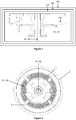
- the watch mechanism 110 comprises a mechanical connection device 100.
- the mechanical connection device 100 is for example a mechanical connection device for a timepiece or a mechanical transmission device for a timepiece.
- the two parts 1, 2 or components 1, 2 have been microstructured at least at a first zone Z1 and a second zone Z2, respectively.
- the first piece is mounted movably relative to a movement frame and the second piece is also mounted movably relative to a frame of the movement.
- the first part 1 is for example leading, while the second part 2 is for example conducted.
- the first part 1 is pivoted about an axis A1 and the second part 2 is pivoted about an axis A2.
- the axes A1, A2 coincide so as to produce a mechanical connection device 100 which is a mechanical transmission device or a mechanical coupling device, for example integrated within a vertical chronograph clutch device.
- the first piece is a first disk of axis A1 and the second part is a second disk of axis A2.
- the chronograph When the chronograph is switched on, the second piece 2, causes a counting chain of the chronograph.
- the second piece 2 is then pressed against a pad 1 formed by the first piece which is engaged with the finishing chain of the watch movement.
- a return element 3 recalls the first and second parts against each other, in particular the first and second zones against each other.
- the first zone Z1 and the second zone Z2 of the components 1 and 2 are represented in gray on the figure 2 .
- the first and second areas are likely to come into contact.
- the first and second zones Z1, Z2 are respectively arranged in a first surface S1 and in a second surface S2.
- the surface S1 is flat and perpendicular or substantially perpendicular to the axis A1.
- the surface S2 is flat and perpendicular or substantially perpendicular to the axis A2.
- the first zone Z1 is a plane ring and the second zone Z2 is a plane ring.
- the two planar rings have substantially the same dimensions or the same areas.
- the first zone Z1 and the second zone Z2 at least partially cover the surfaces S1 and S2, respectively.
- the first zone forms a portion of a first surface S1 of the first part, in particular a first cylindrical or frustoconical surface or plane.
- the second zone forms a portion of a second surface S2 of the second part, in particular a second cylindrical or frustoconical surface or plane
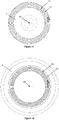
- the first zone Z1 and second zone Z2 include, in this example, approximately 180 microcavities C1 and C2 respectively.
- the geometries of the microcavities C1 and the geometries of the microcavities C2 are identical.
- the microcavities may be microgrooves or microrainings hollowed out radially, at regular intervals.
- the depth P1 of the microcavities C1 can be 8 ⁇ m.
- the width L1 of the microcavities C1 may vary from 30 ⁇ m to 40 ⁇ m along the radial dimension of the first and second zones Z1, Z2.
- the depth P2 of the microcavities C2 may be 8 ⁇ m.
- the width L2 of the microcavities C2 may vary from 30 ⁇ m to 40 ⁇ m along the radial dimension of the first and second zones Z1, Z2.
- the first microcavities C1 and the second microcavities C2, in particular the flanks F1 of the first microcavities and the flanks F2 of the second microcavities C2, are oriented perpendicularly or substantially perpendicularly.
- the microcavities C1 and C2 are microrainings which extend radially relative to the axes A1 and A2, or which are oriented radially relative to the axes A1 and A2.
- the zones Z1 and Z2 are in contact with each other. another at the level of the flanks of the microcavities of an area, that is to say that the flanks of the microcavities of one zone come into contact with the flanks of the microcavities of the other zone.
- vertices between micro-cavities of one zone may also come into contact with funds from the microcavities of the other zone.
- flanks F1 of the microcavities C1 form, with the funds 91 of the microcavities C1, an angle ⁇ .
- the flanks F2 of the microcavities C2 form, with the bottoms 92 of the microcavities C2, an angle ⁇ .
- the angle ⁇ may be straight or obtuse.
- the angle ⁇ is defined so as to adequately transmit the forces E between the first piece and the second piece while allowing a clutch parts 1 and 2, namely a contact flanks F1 against the flanks F2.
- microcavities C1, C2 may be symmetrical or not depending on the orientation of the forces E to be transmitted from the workpiece 1 to the workpiece 2.
- the bottoms 91 of the microcavities C1 and the bottoms 92 of the microcavities C2 may have the form of regulated surfaces, in particular being planes. Alternatively, they can be reduced to one edge or substantially one fish bone.
- the vertices 93 between two microcavities C1 and the vertices 94 between two microcavities C2 may have the form of regulated surfaces, in particular being planes. Alternatively, they can be reduced to an edge or substantially an edge.
- a regulated surface is a surface by each point of which passes a line, called generator, contained in the surface.
- the timepiece comprises a watch movement 120.
- the movement comprises a watch mechanism 110, such as for example a chronograph mechanism or a chronograph module or a correction mechanism.
- the watch mechanism 110 comprises a mechanical connection device 100.
- the second embodiment differs from the first embodiment in that the first microcavities C1 and the second microcavities C2 are oriented parallel or substantially parallel to the forces E transmitted from the first piece to the second piece at the contact between the first and second parts. rooms.
- the microcavities C1 and C2 are microrainings or circular microsillions which extend concentrically to the axes A1 and A2.
- the flanks F1 of the microcavities form, with funds 91 microcavities, an angle ⁇ strictly obtuse.
- the flanks F2 of the microcavities C2 form, with the bottoms 92 of the microcavities, an angle ⁇ strictly obtuse.
- the zones Z1 and Z2 are in contact with each other. other at the flanks of their microcavities.
- the peaks of the microcavities of one zone do not come into contact with the funds of the microcavities of the other zone.
- the axial force exerted by the spring 3 and recalling the zones Z1 and Z2 in contact with one another is taken up at the flanks by inclined forces relative to the axes A1 and A2, that is to say having a radial component.
- This radial component is all the greater as the angle ⁇ approaches 90 °.
- the radial component makes it possible to maximize the mechanical transmission torque that can be transmitted from one of the parts 1 to the other of the parts 2.
- the timepiece comprises a watch movement 120.
- the movement comprises a watch mechanism 110, such as for example a chronograph mechanism or a chronograph module or a correction mechanism.
- the watch mechanism 110 comprises a mechanical connection device 100.
- the third embodiment differs from the first and second embodiments in that the surfaces S1 and S2 on which the zones Z1 and Z2 are formed having the microcavities C1 and C2 are not plane surfaces.
- the surfaces S1 and S2 are advantageously each one a surface of revolution, in particular a cone of revolution S1, S2.
- Zones Z1 and Z2 are each a trunk of this surface of revolution, in particular a trunk of this cone of revolution.
- the surfaces S1 and S2 are advantageously identical.
- the figure 14 is a sectional view, in an engaged configuration or mechanical connection configuration, of the third embodiment of a mechanical coupling device of the clutch device type.
- This clutch device is of the vertical type.
- This clutch device has the specificity of being of the conical type.
- a disc 2 can drive the counting chain of the chronograph and be pressed against a shoe 1, engaged with the finishing chain of the watch movement, under the effect of the pressing force of a spring 3 clutch.
- the zones Z1 and Z2 may or may not have the same number of microcavities C1, C2.
- the geometries of the microcavities C1, C2 may be identical or different.
- the first microcavities C1 and the second microcavities C2, in particular the flanks F1 of the first microcavities and the flanks F2 of the second microcavities C2, are oriented perpendicularly or substantially perpendicular to the forces E transmitted from the first piece to the second piece at the contact between the first and second pieces.
- the microcavities C1 and C2 are microrainings which preferably extend towards the vertices of the surfaces S1 and S2.
- the surface S1 is preferably an outer surface, that is to say a surface of the first piece forming a convexity.
- the surface S2 is preferably an inner surface, that is to say a surface of the second piece forming a concavity.
- the first zone Z1 is formed on the first outer surface S1 and the second zone Z2 is formed on the second inner surface S2.
- the timepiece comprises a watch movement 120.
- the movement comprises a watch mechanism 110, such as for example a chronograph mechanism or a chronograph module or a correction mechanism.
- the watch mechanism 110 comprises a mechanical connection device 100.
- the fourth embodiment differs from the preceding embodiments in that it is applied to a radial clutch device whose operating principle is such as that described, for example, in the patent application. EP2085832 .
- a driving component 1 is capable of driving a driven component 2 comprising a spring 2r which is integral with a mobile 2m, and which is capable of producing a radial clamping force against a cylindrical surface S1 of component 1.
- the spring 2r comprises one or more resilient arms with surfaces S2 may come into contact with the surface S1 of the component 1.
- the spring 2r can be actuated by a related actuating device so that the driving component 1 can lead the driven component 2 in one or two directions of rotation under the effect of the pressure force of the spring 2r.
- the resilient arms can flex and the driving component rotates without driving the driven component.
- component 2 here we mean the component 2 which includes the mobile 2m and the spring 2r.
- Component 2 may also be in the form of a one-piece component having a return spring function.
- the first zone Z1 is preferably a portion of a revolution cylinder S1 of axis of revolution A1 and the second zone or zones Z2 advantageously consist of portions of a regulated surface S2 having parallel generatrices. to the axis A1 of the revolution cylinder S1.
- the number of zones Z2 preferably corresponds to the number of arms of the spring 2r.
- the first zone Z1 is preferably microstructured internally and the second zone Z2 is preferably microstructured externally.
- the two microstructured zones can come into contact during operation of the device.
- the timepiece comprises a watch movement 120.
- the movement comprises a watch mechanism 110, such as a watch cylinder.
- the watch mechanism 110 comprises a mechanical connection device 100.
- the fifth embodiment differs from the previous embodiments in that it is applied to a mechanical barrel spring linkage to a barrel drum.
- the mechanical connection device makes it possible to control the torque of a clock spring, particularly within a barrel of a self-winding watch.
- the solution is to frictionally couple the barrel spring with the inner wall of the barrel drum.
- one or more microstructured zones Z2 are provided in an inner wall S2 of the barrel drum 2 so as to control, and in particular to maximize, as much as possible the sliding torque of the spring relative to the drum.
- the spring in particular a flange 1 of the spring, is also microstructured so that the microcavities C1 and C2 respectively formed on the spring and the drum cooperate by contact.
- the microstructures formed on the inner wall of the drum may be formed, at least in part, on the walls S2 of at least one notch formed in the drum as shown in FIG. figure 20 .
- the spring 1 here serves as the driving component of the barrel drum 2 under the effect of its unwinding.
- the device In function of manual or automatic winding of the movement, and beyond a predefined maximum winding torque of the spring 1, the device is provided to separate the spring 1 from the drum 2.
- the timepiece comprises a watch movement 120.
- the movement comprises a watch mechanism 110, such as for example a chronograph mechanism or a chronograph module or a correction mechanism.
- the watch mechanism 110 comprises a mechanical connection device 100.
- the sixth embodiment differs from the previous embodiments in that it is applied to a horizontal clutch device in which the axes A1 and A2 of the first and second components 1, 2 are parallel or substantially parallel so as to implement a coupling device is for example integrated within a horizontal chronograph clutch device.
- the center distance A1-A2 may vary depending on the configuration, engaged or not, of the clutch device.
- the component 1, pivoted along an axis A1 is disposed on a clutch rocker 4 which is movable relative to the frame of the movement along an axis A4.
- the return spring 3 recalls the rocker to a return position in which the first component 1 is in contact with the second component 2.
- the zone Z1 of the peripheral surface S1 of the driving component 1 engaged with the finishing line of a watch movement, in particular with a chronograph driving wheel, is pressed against of the zone Z2 of the peripheral surface S2 of the driven component 2.
- the components 1 and 2 can thus be likened to wheels devoid of teeth whose friction drive is optimized via the microcavities C1 and C2 zones Z1, Z2, in particular through flanks F1, F2 microcavities C1, C2, provided to cooperate by contact with each other.
- Such an embodiment is particularly advantageous in the context of a horizontal chronograph clutch device, which may be subject to the risk of clogging, namely a more or less random movement of the second hand to the engagement of the chronograph, the makes the size and geometry of conventional teeth involved in this type of clutch.
- the microstructured surfaces S1 and S2 are here cylindrical. Alternatively, these surfaces may form an angle relative to their respective axis of revolution A1, A2.
- the components 1 and 2 may comprise elastic arms B1, B2 so as to generate a prestress plating the surfaces S1, S2 against each other, like the device disclosed in the document EP3051364 . Alternatively, this prestressing can be generated by any other return means.
- the zone Z1 of the surface S1 of the component 1 may also be provided to cooperate with a microstructured zone Z5 of the peripheral surface S5 of the chronograph driving wheel 5.
- the first microcavities C1 and the second microcavities C2, in particular the flanks F1 of the first microcavities and the flanks F2 of the second microcavities C2, are oriented perpendicularly or substantially perpendicular to the forces E transmitted from the first piece to the second piece at the contact between the first and second pieces.
- the microcavities C1 and C2 are preferably microrainings which extend preferentially parallel to the axes A1 and A2.
- the first zone Z1 is externally microstructured and the second zone Z2 is microstructured externally.
- one of the first and second zones could alternatively be microstructured internally.
- the timepiece comprises a watch movement 120.
- the movement comprises a watch mechanism 110, such as a winding mechanism and / or correction to the rod or a correction mechanism.
- the watch mechanism 110 comprises a mechanical connection device 100.
- the seventh embodiment differs from the sixth embodiment in that the surfaces S1 and S2 on which the zones Z1 and Z2 are formed having the microcavities C1 and C2 are not cylinders.
- the surfaces S1 and S2 are cones or cone portions of revolution S1, S2.
- Zones Z1 and Z2 are each arranged on a trunk of these cones.
- the two cones (of surfaces S1, S2) can have the same vertex.
- the axes A1, A2 of the first and second components are concurrent, in particular perpendicular, so as to implement a coupling device, for example integrated within a clutch device to the winding stem.
- the component 1 can move axially along the axis A1 according to the configuration, engaged or not, of the clutch device.
- the component 1 may, for example, take the form of a winding pinion 1 integral with a winding stem 6 which can be positioned axially by means of a conventional rod mechanism.
- the led component 2 can take the form of a winding crown 2.
- Such an embodiment is particularly advantageous in the context of a conventional mechanism of winding and / or correction to the rod, which may be subject to the risk of jamming.
- This risk results in a scratching sensation when activating the functions, or even an axial locking of the rod when the winding or adjustment chains are under tension.
- This risk is inherent in the size and geometry of the conventional teeth involved in this type of clutch.
- the microstructured surfaces S1 and S2 are here preferably frustoconical.
- the generatrices of the surfaces S1 and S2 can form the same angle.
- the generatrices of the surfaces S1 and S2 form an angle of 45 ° with respect to the axes A1 and A2.
- these surfaces can of course be cylindrical.
- the first microcavities C1 and the second microcavities C2, in particular flanks F1 of the first microcavities and flanks F2 of the second microcavities C2, are oriented perpendicularly or substantially perpendicularly to the forces E transmitted from the first piece to the second piece at the contact between the first and second pieces.
- the microcavities C1 and C2 are preferentially microrainings which preferably extend respectively along the generatrices of the cones S1, S2.
- the first zone Z1 is externally microstructured and the second zone Z2 is microstructured externally.
- the timepiece comprises a watch movement 120.
- the movement comprises a watch mechanism 110, such as a correction mechanism.
- the watch mechanism 110 comprises a mechanical connection device 100.
- the eighth embodiment differs from the previous embodiments in that the first part 1 is a movably mounted part relative to the frame, in particular is a first mobile or a first wheel, and in that the second part 2 is a fixed mounted part relative to the building, in particular is a draft of frame.
- the first part 1 is a movably mounted part relative to the frame, in particular is a first mobile or a first wheel
- the second part 2 is a fixed mounted part relative to the building, in particular is a draft of frame.
- the first part 1 is for example a driving part provided to cooperate with a mobile 2 'led and to cooperate also with the second part 2.
- the mobile 2' is for example a disk having date indications.
- the first piece 1 and the second piece 2 are microstructured.
- the axis A1 of the first part and the axis A2 'of the mobile 2' are parallel or substantially parallel so as to implement a unidirectional coupling device used, for example, within a mechanism of rapid correction of at least one calendar indication, for example an indication of the dates.
- the center distance A1-A2 ' may vary depending on the configuration of the correction mechanism (mechanical connection configuration or configuration without mechanical connection).
- This mechanism comprises an intermediate correction wheel 7 which is engaged with the first part 1 of a mobile M1 able to move between two positions.
- the first piece 1 is disposed within an oblong cutout 11 'formed in the second piece which is preferably a blank 2, in particular a bridge 2 correction.
- the first piece 1 is likely to pass from a first non-correction position represented on the figure 24 at a second correction position of the disk 2 'of the dates represented on the figure 25 according to the direction of rotation of a not shown winding rod and adapted to drive the intermediate wheel 7.
- the mobile M1 advantageously comprises a date correction star 11, a date correction wheel 12 and the first piece comprising a plug 1 or consists of a plug 1.
- the star 11 is intended to cause a conventional toothing 2 'disk, the wheel 12 is engaged with the intermediate wheel 7, while the plug 1 is provided to be housed within the oblong cut 11' of the bridge 2 correction and corresponds to the first piece 1.
- the first microstructured zone Z1 is formed on the periphery of the plug 1 as shown in FIGS. figures 26 and 27 and the second microstructured zone Z2 is formed on the flanks of the cut 11 'of the bridge as shown in FIGS. figures 26 and 27 .
- the surface S1 is a cylinder of revolution and the surface S2 is a cylinder whose generating curve is on the flanks of the cut 11 'of the bridge.
- the microcavities C1, C2, in particular the flanks F1, F2 of the microcavities, are provided to cooperate with each other.
- the first microcavities C1 and the second microcavities C2, in particular the flanks F1 of the first microcavities and the flanks F2 of the second microcavities C2, are oriented perpendicularly or substantially perpendicular to the direction of the movement of the first piece 1 relative to the second piece at the surfaces on which the microcavities are made.
- the microcavities C1 and C2 are microrainings which preferably extend parallel to the axis A1.
- the first zone Z1 is externally microstructured and the second zone Z2 is microstructured internally.
- the microstructured zones Z1, Z2 are formed on a plane surface S1 constituting at least a part of a plate of the first part 12 and on a surface S2 constituting at least a part of a face of the bridge 2.
- the first piece comprises the wheel 12 or consists of the wheel 12.
- the microcavities C1 and C2 can here be formed by a laser strafing to increase the roughness of zones Z1 and Z2 of the surfaces S1 and S2 and thus control , in particular substantially increasing, the pivoting torque of the first part 1 relative to the bridge 2.
- the method may comprise a preliminary step of coating a first zone of the first surface S1 of the first part of a friction reducing layer, in particular a carbon-based layer, in particular graphene-based, and / or a prior step of coating a second zone of the second surface S2 of the second part of a friction reducing layer, in particular based on carbon, in particular based on graphene.
- the coating is thinner than the depth of the machining of microcavities that are performed later.
- the laser structuring then makes it possible to eliminate the coating of the microcavities C1, C2, in particular flanks F1, F2 of the microcavities, by machining them through the coating.
- the zones Z1, Z2 can be completely coated.
- the coating may, for example, be a solid carbon-based friction reducing coating, particularly based on graphene.
- the coating could be a DLC coating (Diamond Like Carbon) whose coefficient of friction is known to be very low in contact with the materials of the movement, for example less than 0.1, and whose hardness is very high, for example able to up to about 90 GPa.
- the coating may consist of nanocrystalline diamond or may incorporate carbon nanotubes.
- the microstructured zones Z1, Z2 are obtained by the treatment steps mentioned above. These processing steps make it possible to form networks of microcavities C1, C2 produced by means of a laser, preferably by means of a laser whose duration of the pulses is of the order of the femtosecond. Pulse duration can range from femtosecond to picosecond.
- the laser is set in motion so that it sweeps, at least partially, the surfaces S1, S2 of the components 1 and 2, in particular that it scans the zones Z1 and Z2 of the components 1 and 2.
- the parts can be set in motion relative to the laser.
- microstructured zones Z1 and Z2 comprise microcavities C1, C2.
- the microcavities C1 are advantageously microrainings and / or the microcavities C2 are advantageously microrainures.
- the microrainings may advantageously extend linearly, that is to say along straight lines D1 as shown in FIG. figure 9 .
- the microrainures can extend along curves on the surfaces where they are made.
- the first microcavities have a depth less than 100 ⁇ m or less than 50 ⁇ m or less than 25 ⁇ m and / or the second microcavities have a depth of less than 100 ⁇ m or less than 50 ⁇ m or less than 25 ⁇ m. More preferably, the first and second microcavities have the same depth or substantially the same depth.
- the first microcavities have a width L1 of less than 200 ⁇ m or less than 150 ⁇ m or less than 100 ⁇ m and / or the second microcavities have a width of less than 200 ⁇ m or less than 150 ⁇ m. or less than 100 ⁇ m. More preferably, the first and second microcavities have the same width or substantially the same width.
- the width of the microcavity bottoms may be substantially equal to the width of the conformations separating two contiguous or adjacent microcavities.
- the zones Z1 and Z2 comprise the same number of microcavities C1, C2.
- the zones Z1 and Z2 may comprise a different number of microcavities C1, C2.
- the microcavities C1 have a crenellated shape, especially with a depth P1 and a width L1.
- the microcavities C2 have the form of crenellations, in particular with a depth P2 and a width L2.
- the microcavities C1, C2 have the same geometry.
- the depths P1 and P2 are equal or substantially equal and the widths L1 and L2 are equal or substantially equal.
- the microcavities have flanks forming an angle ⁇ of between 90 ° and 160 ° from the bottoms of the first microcavities and / or the second microcavities have flanks forming an angle ⁇ of between 90 °. and 160 ° from the bottoms of the second microcavities.
- the geometry, in particular the depth P1 and / or the width L1 and / or the angle ⁇ of the microcavities C1 and / or C2 may vary over all the zones Z1, Z2, in particular vary along certain or each of the microcavities.
- the slots formed by the microcavities and represented on the figure 9 are symmetrical. Of course, they could be asymmetrical so as to favor a direction of mechanical connection of the components 1 and 2. In such a case, the transmissible force from the first piece to the second piece can be different in a first direction of training. the first piece and in a second driving direction of the first piece, the second direction being opposite the first direction.
- microcavities C1, C2 are preferably provided for cooperating dry.
- two contiguous first microcavities are separated by a first interspecific conformation that can form a vertex 93 and / or, in the second zone Z2, two contiguous second microcavities are separated by a second intermediate conformation that can form a peak 94.
- the width of intermediate conformations separating two contiguous or adjacent microcavities is less than 150 microns, or even less than 100 microns, or even less than 50 microns.
- the intermediate conformations may be reduced to an edge or substantially an edge.
- the microcavities can also be of "submicron” dimensions, in particular “nanometric” dimensions.
- the term “microcavity” is indifferently used for both sub-micron structures and micron-sized structures, as well as for structures larger than one micron. The same goes for the term “microrainure”.
- FIG 10 illustrates a graph comparing the holding torque CA of a clutch known from the prior art, such as that illustrated in FIGS. Figures 1 and 2 but which would not present the microcavities, and the clutch holding torque CB such as that illustrated on the Figures 1 and 2 with surfaces S1 and S2 having zones Z1 and Z2 provided with microcavities C1, C2 such as those represented more particularly on the Figures 3 to 9 .
- holding torque we mean the minimum torque necessary to rotate the first part of an angle ⁇ relative to the second part 2 in the engaged configuration of the clutch device (or mechanical connection configuration).
- the figure 10 indicates a gain of the order of a factor of 4 between the average torque CA according to the angle ⁇ and the average of the peaks of the torque signal CB according to the angle ⁇ .
- the transmission torque of the clutch is increased by a factor of 4.
- Torque measurements have also been made on clutches whose second part 2 comprises only two microcavities C2 equi-distributed around the axis A2 and whose geometries are identical to those of the 180 microcavities C1 of the first part 1. It can be seen that that the torque signal CB is similar to that illustrated by the figure 10 . Thus, it is also noted that for the same clutch spring 3, the transmission torque of the clutch is increased by a factor of 4 relative to a clutch known from the prior art.
- the microcavities C1 and C2 cooperate with each other. In particular, they cooperate by obstacle, particularly by obstacle at their flanks.
- Microcavities do not form gear teeth. Microcavities can not be assimilated to gear teeth, especially because of their geometry.
- the contact of the flanks F1, F2 of microcavities C1, C2 is permanent when the connection device is activated. For example, when the connection device is activated, a large number, in particular a number greater than 3, or even greater than 5, or even greater than 10, or all the microcavities of one of the first and second parts are in contact, in particular in permanent contact with the microcavities of the other room.
- the devices of the first, second, third, fourth and fifth embodiments are connecting devices.
- the first and second parts are moved as a single piece (except sliding) when the device is activated, that is to say that the first and second parts remain fixed relative to each other (except slip).
- flanks F1 are brought into contact consecutively with sidewalls F2 which are adjacent when the device is activated, which promotes the adhesion of surfaces S1, S2, especially zones Z1, Z2.
- a limited number, in particular a number less than 10, or even less than 5, or even less than 3, of microcavities of one of the first and second parts are in contact, in particular in sequential contact with the microcavities of the other room.
- the connecting devices of the sixth and seventh embodiments are transmission devices.
- the first and second parts are moved in dependence of one another.
- the two pieces roll over each other, in particular without sliding with respect to one another.
- a biasing member recalls the first zone and second zone in contact with each other. More preferably, no stop is provided to limit the approximation of the first and second parts of one another. In particular, in the sixth embodiment, preferably, no stop is provided to maintain a minimum distance between the first and second parts.
- the device of the eighth embodiment is a particular link device. It allows friction between the first and second parts.
- the first piece moves independently of the second piece, i.e. sliding between the parts without however that one or the other of the first and second parts is deteriorated.
- two flanks of microcavities cease to cooperate with each other and the pieces slide relative to each other until at least one of the flanks of the first piece cooperates again by contact, in particular by obstacle, with at least one of the flanks of the second piece.
- the microcavities are used in cooperation with one another or to provide a mechanical connection of the mechanical drive type of a part by another (this is the case of the first seven embodiments), or to achieve a friction type mechanical connection or notching from one part to another (this is the case eighth embodiment).
- the first configuration is an engaged configuration and the second configuration is a disengaged configuration.
- the mechanical connecting device can be permanently maintained (except disassembly or maintenance operation) in a mechanical connection configuration in which the first and second areas are in contact with each other.
- microcavities on areas of the parts can make it possible to achieve decorative effects on these areas and / or optical effects on these areas, especially moire effects. These effects are advantageously used, in particular to customize the aspects of the parts.
- microcavities makes it possible to produce zones whose roughness or surface conditions are controlled. These surface states or roughnesses are advantageously used to optimize, control or maximize frictional forces between different parts.
Abstract
Dispositif de liaison mécanique (100), notamment dispositif de liaison mécanique pour pièce d'horlogerie ou dispositif de transmission mécanique pour pièce d'horlogerie, comprenant :
- une première pièce (1) comprenant une première zone présentant au moins une première microcavité, et
- une deuxième pièce (2) comprenant une deuxième zone présentant au moins une deuxième microcavité,
les première et deuxième zones étant en contact l'une avec l'autre dans une configuration de liaison mécanique.

a first part (1) comprising a first zone having at least a first microcavity, and
a second part (2) comprising a second zone having at least a second microcavity,
the first and second zones being in contact with one another in a mechanical connection configuration.
Description
L'invention concerne un dispositif de liaison mécanique pour pièce d'horlogerie. L'invention concerne aussi un mécanisme horloger comprenant un tel dispositif de liaison. L'invention concerne encore un mouvement horloger comprenant un tel dispositif ou un tel mécanisme. L'invention concerne également une pièce d'horlogerie comprenant un tel dispositif ou un tel mécanisme ou un tel mouvement.The invention relates to a mechanical connection device for a timepiece. The invention also relates to a clock mechanism comprising such a connecting device. The invention also relates to a watch movement comprising such a device or such a mechanism. The invention also relates to a timepiece comprising such a device or such a mechanism or such a movement.
On connaît des embrayages horlogers, en particulier des embrayages verticaux, au sein desquels deux composants sont susceptibles d'être solidarisés à friction sous l'effet d'une force produite par un moyen de rappel. De telles solutions ne sont toutefois pas optimales en regard du couple transmis par l'embrayage vis-à-vis de la force produite par le moyen de rappel. Il s'avère ainsi difficile d'augmenter le couple transmis par un embrayage horloger étant donné que la force produite par le moyen de rappel ne peut être augmentée indéfiniment, notamment en regard de considérations énergétiques, de contraintes mécaniques, et d'encombrements. Par ailleurs, les embrayages horlogers connus de l'art antérieur peuvent être sujets à des risques de chevrotement ou d'arc-boutement, voire de blocage.Watch clutches, in particular vertical clutches, in which two components are capable of being frictionally fastened under the effect of a force produced by a return means are known. Such solutions are however not optimal with respect to the torque transmitted by the clutch vis-à-vis the force produced by the biasing means. It is thus difficult to increase the torque transmitted by a clock clutch since the force produced by the return means can not be increased indefinitely, particularly with regard to energy considerations, mechanical stresses, and congestion. Moreover, watch clutches known from the prior art may be subject to risks of kinking or jamming or blocking.
On connaît du document
On connaît de la demande de brevet
Des composants horlogers dont l'état de surface est modifié au moyen d'un laser sont, par ailleurs, connus de l'art antérieur. La demande de brevet
Le but de l'invention est de fournir un dispositif de liaison permettant de remédier aux inconvénients mentionnés précédemment et d'améliorer les dispositifs connus de l'art antérieur. En particulier, l'invention propose un dispositif de liaison mécanique qui peut être maximisé indépendamment de forces de rappel agissant sur des éléments du dispositif de liaison mécanique.The object of the invention is to provide a connecting device to overcome the disadvantages mentioned above and to improve the known devices of the prior art. In particular, the invention proposes a mechanical connection device that can be maximized independently of restoring forces acting on elements of the mechanical connection device.
Selon l'invention, un dispositif de liaison est défini par la revendication 1.According to the invention, a connecting device is defined by
Différents modes de réalisation d'un dispositif de liaison sont définis par les revendications 2 à 9 et 12.Different embodiments of a connecting device are defined by
Selon l'invention, un procédé de fabrication est défini par la revendication 10.According to the invention, a manufacturing method is defined by claim 10.
Un mode de réalisation d'un procédé de fabrication est défini par la revendication 11.An embodiment of a manufacturing method is defined by
Selon l'invention, un mécanisme horloger est défini par la revendication 13.According to the invention, a clock mechanism is defined by claim 13.
Selon l'invention, un mouvement horloger est défini par la revendication 14.According to the invention, a watch movement is defined by claim 14.
Selon l'invention, une pièce d'horlogerie est définie par la revendication 15.According to the invention, a timepiece is defined by claim 15.
Les figures annexées représentent, à titre d'exemples, différents modes de réalisation d'une pièce d'horlogerie selon l'invention.
- Les
figures 1 à 10 sont des vues d'un premier mode de réalisation d'une pièce d'horlogerie selon l'invention comprenant un premier mode de réalisation d'un dispositif de liaison mécanique. - Les
figures 11 à 13 sont des vues d'un deuxième mode de réalisation d'une pièce d'horlogerie selon l'invention comprenant un deuxième mode de réalisation d'un dispositif de liaison mécanique. - Les
figures 14 à 16 sont des vues d'un troisième mode de réalisation d'une pièce d'horlogerie selon l'invention comprenant un troisième mode de réalisation d'un dispositif de liaison mécanique. - Les
figures 17 et 18 sont des vues d'un quatrième mode de réalisation d'une pièce d'horlogerie selon l'invention comprenant un quatrième mode de réalisation d'un dispositif de liaison mécanique. - Les
figures 19 et 20 sont des vues d'un cinquième mode de réalisation d'une pièce d'horlogerie selon l'invention comprenant un cinquième mode de réalisation d'un dispositif de liaison mécanique. - Les
figures 21 et 22 sont des vues d'un sixième mode de réalisation d'une pièce d'horlogerie selon l'invention comprenant un sixième mode de réalisation d'un dispositif de liaison mécanique. - La
figure 23 est une vue d'un septième mode de réalisation d'une pièce d'horlogerie selon l'invention comprenant un septième mode de réalisation d'un dispositif de liaison mécanique. - Les
figures 24 à 27 sont des vues d'une première variante de réalisation d'un huitième mode de réalisation d'une pièce d'horlogerie selon l'invention comprenant une première variante de réalisation d'un huitième mode de réalisation d'un dispositif de liaison mécanique. - La
figure 28 est une vue d'une deuxième variante de réalisation du huitième mode de réalisation d'une pièce d'horlogerie selon l'invention comprenant une deuxième variante de réalisation du huitième mode de réalisation d'un dispositif de liaison mécanique.
- The
Figures 1 to 10 are views of a first embodiment of a timepiece according to the invention comprising a first embodiment of a mechanical connection device. - The
Figures 11 to 13 are views of a second embodiment of a timepiece according to the invention comprising a second embodiment of a mechanical connection device. - The
Figures 14 to 16 are views of a third embodiment of a timepiece according to the invention comprising a third embodiment of a mechanical connection device. - The
Figures 17 and 18 are views of a fourth embodiment of a timepiece according to the invention comprising a fourth embodiment of a mechanical connection device. - The
Figures 19 and 20 are views of a fifth embodiment of a timepiece according to the invention comprising a fifth embodiment of a mechanical connection device. - The
Figures 21 and 22 are views of a sixth embodiment of a timepiece according to the invention comprising a sixth embodiment of a mechanical connection device. - The
figure 23 is a view of a seventh embodiment of a timepiece according to the invention comprising a seventh embodiment of a mechanical connection device. - The
Figures 24 to 27 are views of a first variant embodiment of an eighth embodiment of a timepiece according to the invention comprising a first variant embodiment of an eighth embodiment of a mechanical connection device. - The
figure 28 is a view of a second embodiment of the eighth embodiment of a timepiece according to the invention comprising a second embodiment of the eighth embodiment of a mechanical connection device.
Un premier mode de réalisation d'une pièce d'horlogerie 130 est décrit ci-après en référence aux
Le mécanisme horloger 110 comprend un dispositif de liaison mécanique 100.The
Le dispositif de liaison mécanique 100 est par exemple un dispositif de liaison mécanique pour une pièce d'horlogerie ou un dispositif de transmission mécanique pour une pièce d'horlogerie.The
Le dispositif de liaison mécanique 100 comprend :
- une
première pièce 1 comprenant une première zone Z1 présentant au moins une première microcavité C1, et - une
deuxième pièce 2 comprenant une deuxième zone Z2 présentant au moins une deuxième microcavité C2,
- a
first part 1 comprising a first zone Z1 having at least a first microcavity C1, and - a
second part 2 comprising a second zone Z2 having at least a second microcavity C2,
Dans le premier mode de réalisation, les deux pièces 1, 2 ou composants 1, 2 ont été microstructurés au moins au niveau d'une première zone Z1 et d'une deuxième zone Z2, respectivement. La première pièce est montée mobile par rapport à un bâti du mouvement et la deuxième pièce est, elle aussi, montée mobile par rapport à un bâti du mouvement. La première pièce 1 est par exemple menante, tandis que la deuxième pièce 2 est par exemple menée.In the first embodiment, the two
Dans ce premier mode de réalisation, la première pièce 1 est pivotée autour d'un axe A1 et la deuxième pièce 2 est pivotée autour d'un axe A2. De préférence, les axes A1, A2 coïncident de façon à réaliser un dispositif 100 de liaison mécanique qui soit un dispositif de transmission mécanique ou un dispositif d'accouplement mécanique, par exemple intégré au sein d'un dispositif d'embrayage vertical de chronographe.In this first embodiment, the
De préférence, la première pièce est un premier disque d'axe A1 et la deuxième pièce est un deuxième disque d'axe A2. Lorsque le chronographe est enclenché, la deuxième pièce 2, entraîne une chaîne de comptage du chronographe. La deuxième pièce 2 est alors plaquée à l'encontre d'un patin 1 formé par la première pièce qui est en prise avec la chaîne de finissage du mouvement horloger.Preferably, the first piece is a first disk of axis A1 and the second part is a second disk of axis A2. When the chronograph is switched on, the
Un élément de rappel 3, notamment un élément de rappel élastique comme un ressort, rappelle les première et deuxième pièces l'une contre l'autre, en particulier les première et deuxième zones l'une contre l'autre.A
Dans cette construction particulière, la première zone Z1 et la deuxième zone Z2 des composants 1 et 2 sont représentées grisées sur la
La première zone forme une portion d'une première surface S1 de la première pièce, notamment une première surface cylindrique ou tronconique ou plane. La deuxième zone forme une portion d'une deuxième surface S2 de la deuxième pièce, notamment une deuxième surface cylindrique ou tronconique ou planeThe first zone forms a portion of a first surface S1 of the first part, in particular a first cylindrical or frustoconical surface or plane. The second zone forms a portion of a second surface S2 of the second part, in particular a second cylindrical or frustoconical surface or plane
Les première zone Z1 et deuxième zone Z2 comportent notamment dans cet exemple respectivement environ 180 microcavités C1 et C2. De préférence, les géométries des microcavités C1 et les géométries des microcavités C2 sont identiques. Dans cette construction particulière, les microcavités peuvent être des microsillons ou des microrainures creusés radialement, à intervalles réguliers. La profondeur P1 des microcavités C1 peut être de 8 µm. La largeur L1 des microcavités C1 peut évoluer de 30 µm à 40 µm le long de la dimension radiale des première et deuxième zones Z1, Z2. La profondeur P2 des microcavités C2 peut être de 8 µm. La largeur L2 des microcavités C2 peut évoluer de 30 µm à 40 µm le long de la dimension radiale des première et deuxième zones Z1, Z2.The first zone Z1 and second zone Z2 include, in this example, approximately 180 microcavities C1 and C2 respectively. Preferably, the geometries of the microcavities C1 and the geometries of the microcavities C2 are identical. In this particular construction, the microcavities may be microgrooves or microrainings hollowed out radially, at regular intervals. The depth P1 of the microcavities C1 can be 8 μm. The width L1 of the microcavities C1 may vary from 30 μm to 40 μm along the radial dimension of the first and second zones Z1, Z2. The depth P2 of the microcavities C2 may be 8 μm. The width L2 of the microcavities C2 may vary from 30 μm to 40 μm along the radial dimension of the first and second zones Z1, Z2.
De préférence, dans ce mode de réalisation, les premières microcavités C1 et les deuxièmes microcavités C2, en particulier les flancs F1 des premières microcavités et les flancs F2 des deuxièmes microcavités C2, sont orientées perpendiculairement ou sensiblement perpendiculairement aux efforts E transmis de la première pièce à la deuxième pièce au niveau du contact entre les première et deuxième pièces, en particulier au niveau des zones Z1, Z2,. Ainsi, dans ce premier mode de réalisation, les microcavités C1 et C2 sont des microrainures qui s'étendent radialement relativement aux axes A1 et A2, soit qui sont orientées radialement relativement aux axes A1 et A2.Preferably, in this embodiment, the first microcavities C1 and the second microcavities C2, in particular the flanks F1 of the first microcavities and the flanks F2 of the second microcavities C2, are oriented perpendicularly or substantially perpendicularly. the forces E transmitted from the first piece to the second piece at the contact between the first and second pieces, in particular at the Z1, Z2, zones. Thus, in this first embodiment, the microcavities C1 and C2 are microrainings which extend radially relative to the axes A1 and A2, or which are oriented radially relative to the axes A1 and A2.
Dans ce mode de réalisation, lorsque les première et deuxième zones sont en contact l'une avec l'autre, c'est-à-dire dans une configuration de liaison mécanique, les zones Z1 et Z2 sont en contact l'une avec l'autre au niveau des flancs des microcavités d'une zone, c'est-à-dire que des flancs des microcavités d'une zone viennent en contact avec des flancs des microcavités de l'autre zone. Eventuellement, des sommets entre des microcavités d'une zone peuvent aussi venir en contact avec des fonds des microcavités de l'autre zone.In this embodiment, when the first and second areas are in contact with each other, i.e. in a mechanical connection configuration, the zones Z1 and Z2 are in contact with each other. another at the level of the flanks of the microcavities of an area, that is to say that the flanks of the microcavities of one zone come into contact with the flanks of the microcavities of the other zone. Optionally, vertices between micro-cavities of one zone may also come into contact with funds from the microcavities of the other zone.
Dans ce mode de réalisation, les flancs F1 des microcavités C1 forment, avec les fonds 91 des microcavités C1, un angle α. De même, les flancs F2 des microcavités C2 forment, avec les fonds 92 des microcavités C2, un angle α. Préférentiellement, l'angle α peut être droit ou obtus. L'angle α est défini de façon à transmettre de façon adéquate les efforts E entre la première pièce et la deuxième pièce tout en permettant un embrayage des pièces 1 et 2, à savoir un contact des flancs F1 à l'encontre des flancs F2.In this embodiment, the flanks F1 of the microcavities C1 form, with the
Les microcavités C1, C2 peuvent être symétriques ou non en fonction de l'orientation des efforts E à transmettre de la pièce 1 à la pièce 2.The microcavities C1, C2 may be symmetrical or not depending on the orientation of the forces E to be transmitted from the
Les fonds 91 des microcavités C1 et les fonds 92 des microcavités C2 peuvent avoir la forme de surfaces réglées, notamment être des plans. Alternativement, ils peuvent se réduire à une arête ou sensiblement une arête. Les sommets 93 entre deux microcavités C1 et les sommets 94 entre deux microcavités C2 peuvent avoir la forme de surfaces réglées, notamment être des plans. Alternativement, ils peuvent se réduire à une arête ou sensiblement une arête.The
Une surface réglée est une surface par chaque point de laquelle passe une droite, appelée génératrice, contenue dans la surface.A regulated surface is a surface by each point of which passes a line, called generator, contained in the surface.
Un deuxième mode de réalisation d'une pièce d'horlogerie 130 est décrit ci-après en référence aux
Le mécanisme horloger 110 comprend un dispositif de liaison mécanique 100.The
Le deuxième mode de réalisation diffère du premier mode de réalisation en ce que les premières microcavités C1 et les deuxièmes microcavités C2 sont orientées parallèlement ou sensiblement parallèlement aux efforts E transmis de la première pièce à la deuxième pièce au niveau du contact entre les première et deuxième pièces. Ainsi, dans ce deuxième mode de réalisation, les microcavités C1 et C2 sont des microrainures ou des microsillions circulaires qui s'étendent concentriquement aux axes A1 et A2. Dans ce mode de réalisation, les flancs F1 des microcavités forment, avec des fonds 91 des microcavités, un angle α strictement obtus. De même, les flancs F2 des microcavités C2 forment, avec les fonds 92 des microcavités, un angle α strictement obtus.The second embodiment differs from the first embodiment in that the first microcavities C1 and the second microcavities C2 are oriented parallel or substantially parallel to the forces E transmitted from the first piece to the second piece at the contact between the first and second parts. rooms. Thus, in this second embodiment, the microcavities C1 and C2 are microrainings or circular microsillions which extend concentrically to the axes A1 and A2. In this embodiment, the flanks F1 of the microcavities form, with
Dans ce mode de réalisation, lorsque les première et deuxième zones sont en contact l'une avec l'autre, c'est-à-dire dans une configuration de liaison mécanique, les zones Z1 et Z2 sont en contact l'une avec l'autre au niveau des flancs de leurs microcavités. De préférence, les sommets des microcavités d'une zone ne viennent pas en contact avec les fonds des microcavités de l'autre zone.In this embodiment, when the first and second areas are in contact with each other, i.e. in a mechanical connection configuration, the zones Z1 and Z2 are in contact with each other. other at the flanks of their microcavities. Preferably, the peaks of the microcavities of one zone do not come into contact with the funds of the microcavities of the other zone.
Du fait de l'angle α formé entre les fonds et les flancs des microcavités, l'effort axial exercé par le ressort 3 et rappelant les zones Z1 et Z2 en contact l'une contre l'autre, est repris au niveau des flancs par des efforts inclinés relativement aux axes A1 et A2, c'est-à-dire présentant une composante radiale. Cette composante radiale est d'autant plus grande que l'angle α approche de 90°. La composante radiale permet de maximiser le couple de transmission mécanique que l'on peut transmettre de l'une des pièces 1 à l'autre des pièces 2.Because of the angle α formed between the bottoms and the flanks of the microcavities, the axial force exerted by the
Un troisième mode de réalisation d'une pièce d'horlogerie 130 est décrit ci-après en référence aux
Le mécanisme horloger 110 comprend un dispositif de liaison mécanique 100.The
Le troisième mode de réalisation diffère des premier et deuxième modes de réalisation en ce que les surfaces S1 et S2 sur lesquelles sont réalisées les zones Z1 et Z2 présentant les microcavités C1 et C2 ne sont pas des surfaces planes. En effet, dans ce troisième mode de réalisation, les surfaces S1 et S2 sont avantageusement chacune une surface de révolution, notamment un cône de révolution S1, S2. Les zones Z1 et Z2 sont chacune un tronc de cette surface de révolution, notamment un tronc de ce cône de révolution. Les surfaces S1 et S2 sont avantageusement identiques.The third embodiment differs from the first and second embodiments in that the surfaces S1 and S2 on which the zones Z1 and Z2 are formed having the microcavities C1 and C2 are not plane surfaces. Indeed, in this third embodiment, the surfaces S1 and S2 are advantageously each one a surface of revolution, in particular a cone of revolution S1, S2. Zones Z1 and Z2 are each a trunk of this surface of revolution, in particular a trunk of this cone of revolution. The surfaces S1 and S2 are advantageously identical.
La
Comme dans les premier et deuxième modes de réalisation, les zones Z1 et Z2 peuvent présenter ou non le même nombre de microcavités C1, C2. Les géométries des microcavités C1, C2 peuvent être identiques ou non.As in the first and second embodiments, the zones Z1 and Z2 may or may not have the same number of microcavities C1, C2. The geometries of the microcavities C1, C2 may be identical or different.
De préférence, dans ce troisième mode de réalisation, les premières microcavités C1 et les deuxièmes microcavités C2, en particulier les flancs F1 des premières microcavités et les flancs F2 des deuxièmes microcavités C2, sont orientées perpendiculairement ou sensiblement perpendiculairement aux efforts E transmis de la première pièce à la deuxième pièce au niveau du contact entre les première et deuxième pièces. Ainsi, dans ce troisième mode de réalisation, les microcavités C1 et C2 sont des microrainures qui s'étendent préférentiellement en direction des sommets des surfaces S1 et S2. La surface S1 est préférentiellement une surface extérieure, c'est-à-dire une surface de la première pièce formant une convexité. La surface S2 est préférentiellement une surface intérieure, c'est-à-dire une surface de la deuxième pièce formant une concavité.Preferably, in this third embodiment, the first microcavities C1 and the second microcavities C2, in particular the flanks F1 of the first microcavities and the flanks F2 of the second microcavities C2, are oriented perpendicularly or substantially perpendicular to the forces E transmitted from the first piece to the second piece at the contact between the first and second pieces. Thus, in this third embodiment, the microcavities C1 and C2 are microrainings which preferably extend towards the vertices of the surfaces S1 and S2. The surface S1 is preferably an outer surface, that is to say a surface of the first piece forming a convexity. The surface S2 is preferably an inner surface, that is to say a surface of the second piece forming a concavity.
Ainsi, dans ce troisième mode de réalisation, la première zone Z1 est formée sur la première surface extérieure S1 et la deuxième zone Z2 est formée sur la deuxième surface intérieure S2.Thus, in this third embodiment, the first zone Z1 is formed on the first outer surface S1 and the second zone Z2 is formed on the second inner surface S2.
Un quatrième mode de réalisation d'une pièce d'horlogerie 130 est décrit ci-après en référence aux
Le mécanisme horloger 110 comprend un dispositif de liaison mécanique 100.The
Le quatrième mode de réalisation diffère des modes de réalisation précédents en ce qu'il est appliqué à un dispositif d'embrayage radial dont le principe de fonctionnement est tel que celui décrit, par exemple, au sein de la demande de brevet
Par composant mené 2, nous entendons ici le composant 2 qui inclut le mobile 2m et le ressort 2r. Le composant 2 peut également se présenter sous la forme d'un composant monobloc présentant une fonction de ressort de rappel.By led
Les caractères menant et mené des composants peuvent être inversés.The characters leading and leading components can be reversed.
Dans ce quatrième mode de réalisation, la première zone Z1 est préférentiellement une portion d'un cylindre de révolution S1 d'axe de révolution A1 et la ou les deuxièmes zones Z2 consistent avantageusement en des portions d'une surface réglée S2 ayant des génératrices parallèles à l'axe A1 du cylindre de révolution S1. Le nombre de zones Z2 correspond préférentiellement au nombre de bras du ressort 2r.In this fourth embodiment, the first zone Z1 is preferably a portion of a revolution cylinder S1 of axis of revolution A1 and the second zone or zones Z2 advantageously consist of portions of a regulated surface S2 having parallel generatrices. to the axis A1 of the revolution cylinder S1. The number of zones Z2 preferably corresponds to the number of arms of the
Dans ce quatrième mode de réalisation, la première zone Z1 est préférentiellement microstructurée intérieurement et la deuxième zone Z2 est préférentiellement microstructurée extérieurement. Ainsi, les deux zones microstructurées peuvent entrer en contact lors du fonctionnement du dispositif.In this fourth embodiment, the first zone Z1 is preferably microstructured internally and the second zone Z2 is preferably microstructured externally. Thus, the two microstructured zones can come into contact during operation of the device.
Un cinquième mode de réalisation d'une pièce d'horlogerie 130 est décrit ci-après en référence aux
Le mécanisme horloger 110 comprend un dispositif de liaison mécanique 100.The
Le cinquième mode de réalisation diffère des modes de réalisation précédents en ce qu'il est appliqué à une liaison mécanique de ressort de barillet à un tambour de barillet. En particulier, le dispositif de liaison mécanique permet de maîtriser le couple d'un ressort de barillet horloger, notamment au sein d'un barillet d'une montre à remontage automatique. La solution consiste à accoupler à friction le ressort de barillet avec la paroi intérieure du tambour de barillet. Pour ce faire, une ou plusieurs zones microstructurées Z2 sont prévues dans une paroi interne S2 du tambour de barillet 2 de façon à maîtriser, et à maximiser notamment, autant que possible le couple de glissement du ressort relativement au tambour. Préférentiellement, le ressort, en particulier une bride 1 du ressort, est également microstructuré de façon à ce que les microcavités C1 et C2 formées respectivement sur le ressort et le tambour coopèrent par contact. Alternativement, les microstructures formées sur la paroi interne du tambour peuvent être formées, au moins en partie, sur les parois S2 d'au moins une encoche formée dans le tambour comme représenté sur la
En fonctionnement conventionnel du mouvement, le ressort 1 fait ici office de composant menant du tambour 2 de barillet sous l'effet de son dévidement. En fonction de remontage manuel ou automatique du mouvement, et au-delà d'un couple d'armage maximal prédéfini du ressort 1, le dispositif est prévu pour désolidariser le ressort 1 du tambour 2.In conventional operation of the movement, the
Un sixième mode de réalisation d'une pièce d'horlogerie 130 est décrit ci-après en référence aux
Le mécanisme horloger 110 comprend un dispositif de liaison mécanique 100.The
Le sixième mode de réalisation diffère des modes de réalisation précédents en ce qu'il est appliqué à un dispositif d'embrayage horizontal dans lequel les axes A1 et A2 des premier et deuxième composants 1, 2 sont parallèles ou sensiblement parallèles de façon à mettre en oeuvre un dispositif d'accouplement qui est par exemple intégré au sein d'un dispositif d'embrayage horizontal de chronographe.The sixth embodiment differs from the previous embodiments in that it is applied to a horizontal clutch device in which the axes A1 and A2 of the first and
Dans ce sixième mode de réalisation, l'entraxe A1-A2 peut varier en fonction de la configuration, embrayée ou non, du dispositif d'embrayage. Pour ce faire, le composant 1, pivoté selon un axe A1, est disposé sur une bascule 4 d'embrayage qui est mobile relativement au bâti du mouvement selon un axe A4. Le ressort de rappel 3 rappelle la bascule vers une position de rappel dans laquelle le premier composant 1 est en contact avec le deuxième composant 2.In this sixth embodiment, the center distance A1-A2 may vary depending on the configuration, engaged or not, of the clutch device. To do this, the
Ainsi, lorsque le chronographe est enclenché, la zone Z1 de la surface périphérique S1 du composant menant 1, en prise avec la chaîne de finissage d'un mouvement horloger, en particulier avec une roue 5 entraîneuse de chronographe, est plaquée à l'encontre de la zone Z2 de la surface périphérique S2 du composant mené 2. Les composants 1 et 2 peuvent être ainsi assimilés à des roues dénuées de dents dont l'entraînement par friction est optimisé par le biais des microcavités C1 et C2 des zones Z1, Z2, en particulier par le biais des flancs F1, F2 des microcavités C1, C2, prévues pour coopérer par contact les unes avec les autres.Thus, when the chronograph is engaged, the zone Z1 of the peripheral surface S1 of the
Une telle réalisation est particulièrement avantageuse dans le cadre d'un dispositif d'embrayage horizontal de chronographe, qui peut être sujet au risque de chevrotement, à savoir un déplacement plus ou moins aléatoire de la trotteuse de seconde à l'enclenchement du chronographe, du fait de la taille et des géométries des dentures conventionnelles prenant part à ce type d'embrayage.Such an embodiment is particularly advantageous in the context of a horizontal chronograph clutch device, which may be subject to the risk of clogging, namely a more or less random movement of the second hand to the engagement of the chronograph, the makes the size and geometry of conventional teeth involved in this type of clutch.
Les surfaces S1 et S2 microstructurées sont ici cylindriques. Alternativement, ces surfaces peuvent former un angle relativement à leur axe de révolution A1, A2 respectif. Avantageusement, les composants 1 et 2 peuvent comprendre des bras B1, B2 élastiques de façon à générer une précontrainte plaquant les surfaces S1, S2 l'une contre l'autre à l'instar du dispositif divulgué au sein du document
De préférence, dans ce sixième mode de réalisation, les premières microcavités C1 et les deuxièmes microcavités C2, en particulier des flancs F1 des premières microcavités et les flancs F2 des deuxièmes microcavités C2, sont orientées perpendiculairement ou sensiblement perpendiculairement aux efforts E transmis de la première pièce à la deuxième pièce au niveau du contact entre les première et deuxième pièces. Ainsi, dans ce sixième mode de réalisation, les microcavités C1 et C2 sont préférentiellement des microrainures qui s'étendent préférentiellement parallèlement aux axes A1 et A2.Preferably, in this sixth embodiment, the first microcavities C1 and the second microcavities C2, in particular the flanks F1 of the first microcavities and the flanks F2 of the second microcavities C2, are oriented perpendicularly or substantially perpendicular to the forces E transmitted from the first piece to the second piece at the contact between the first and second pieces. Thus, in this sixth embodiment, the microcavities C1 and C2 are preferably microrainings which extend preferentially parallel to the axes A1 and A2.
Dans ce sixième mode de réalisation, la première zone Z1 est microstructurée extérieurement et la deuxième zone Z2 est microstructurée extérieurement. Toutefois, l'une des première et deuxième zones pourrait alternativement être microstructurée intérieurement.In this sixth embodiment, the first zone Z1 is externally microstructured and the second zone Z2 is microstructured externally. However, one of the first and second zones could alternatively be microstructured internally.
Un septième mode de réalisation d'une pièce d'horlogerie 130 est décrit ci-après en référence à la
Le mécanisme horloger 110 comprend un dispositif de liaison mécanique 100.The
Le septième mode de réalisation diffère du sixième mode de réalisation en ce que les surfaces S1 et S2 sur lesquelles sont réalisées les zones Z1 et Z2 présentant les microcavités C1 et C2 ne sont pas des cylindres. En effet, dans ce septième mode de réalisation, les surfaces S1 et S2 sont des cônes ou des portions de cône de révolution S1, S2. Les zones Z1 et Z2 sont chacune disposées sur un tronc de ces cônes. Les deux cônes (de surfaces S1, S2) peuvent avoir un même sommet. Les axes A1, A2 des premier et deuxième composants sont concourants, en particulier perpendiculaires, de façon à mettre en oeuvre un dispositif d'accouplement, par exemple intégré au sein d'un dispositif d'embrayage à la tige de remontoir.The seventh embodiment differs from the sixth embodiment in that the surfaces S1 and S2 on which the zones Z1 and Z2 are formed having the microcavities C1 and C2 are not cylinders. Indeed, in this seventh embodiment, the surfaces S1 and S2 are cones or cone portions of revolution S1, S2. Zones Z1 and Z2 are each arranged on a trunk of these cones. The two cones (of surfaces S1, S2) can have the same vertex. The axes A1, A2 of the first and second components are concurrent, in particular perpendicular, so as to implement a coupling device, for example integrated within a clutch device to the winding stem.
Dans ce mode de réalisation, le composant 1 peut se déplacer axialement selon l'axe A1 selon la configuration, embrayée ou non, du dispositif d'embrayage. Pour ce faire, le composant 1 peut, par exemple, prendre la forme d'un pignon de remontoir 1 solidaire d'une tige 6 de remontoir qui peut être positionnée axialement par le biais d'un mécanisme de tige conventionnel. Le composant mené 2 peut prendre la forme d'une couronne 2 de remontoir.In this embodiment, the
Lorsque l'embrayage est activé, la zone Z1 de la surface périphérique S1 du composant menant 1, en prise avec la tige 6, est plaquée à l'encontre de la zone Z2 de la surface périphérique S2 du composant mené 2 dont l'axe de rotation A2 est fixe par rapport au bâti du mouvement. Les composants 1 et 2 peuvent être ainsi assimilés à des roues dénuées de dents dont l'entraînement par friction est optimisé par le biais des microcavités C1 et C2 des zones Z1, Z2, en particulier par le biais des flancs F1, F2 des microcavités C1, C2 prévues pour coopérer les unes avec les autres.When the clutch is activated, the zone Z1 of the peripheral surface S1 of the
Une telle réalisation est particulièrement avantageuse dans le cadre d'un mécanisme conventionnel de remontage et/ou de correction à la tige, qui peut être sujet au risque d'arc-boutement. Ce risque se traduit par une sensation de grattement lors de l'activation des fonctions, voire par un blocage axial de la tige lorsque les chaînes de remontage ou de réglage sont sous tension. Ce risque est inhérent à la taille et aux géométries des dentures conventionnelles prenant part à ce type d'embrayage.Such an embodiment is particularly advantageous in the context of a conventional mechanism of winding and / or correction to the rod, which may be subject to the risk of jamming. This risk results in a scratching sensation when activating the functions, or even an axial locking of the rod when the winding or adjustment chains are under tension. This risk is inherent in the size and geometry of the conventional teeth involved in this type of clutch.
Les surfaces S1 et S2 microstructurées sont ici préférentiellement tronconiques. Les génératrices des surfaces S1 et S2 peuvent former un même angle. Préférentiellement, les génératrices des surfaces S1 et S2 forment un angle de 45° par rapport aux axes A1 et A2. Alternativement, ces surfaces peuvent bien sûr être cylindriques.The microstructured surfaces S1 and S2 are here preferably frustoconical. The generatrices of the surfaces S1 and S2 can form the same angle. Preferably, the generatrices of the surfaces S1 and S2 form an angle of 45 ° with respect to the axes A1 and A2. Alternatively, these surfaces can of course be cylindrical.
De préférence, dans ce septième mode de réalisation, les premières microcavités C1 et les deuxièmes microcavités C2, en particulier des flancs F1 des premières microcavités et des flancs F2 des deuxièmes microcavités C2, sont orientées perpendiculairement ou sensiblement perpendiculairement aux efforts E transmis de la première pièce à la deuxième pièce au niveau du contact entre les première et deuxième pièces. Ainsi, dans ce septième mode de réalisation, les microcavités C1 et C2 sont préférentiellement des microrainures qui s'étendent préférentiellement respectivement selon des génératrices des cônes S1, S2.Preferably, in this seventh embodiment, the first microcavities C1 and the second microcavities C2, in particular flanks F1 of the first microcavities and flanks F2 of the second microcavities C2, are oriented perpendicularly or substantially perpendicularly to the forces E transmitted from the first piece to the second piece at the contact between the first and second pieces. Thus, in this seventh embodiment, the microcavities C1 and C2 are preferentially microrainings which preferably extend respectively along the generatrices of the cones S1, S2.
Dans ce septième mode de réalisation, la première zone Z1 est microstructurée extérieurement et la deuxième zone Z2 est microstructurée extérieurement.In this seventh embodiment, the first zone Z1 is externally microstructured and the second zone Z2 is microstructured externally.
Un huitième mode de réalisation d'une pièce d'horlogerie 130 est décrit ci-après en référence aux
Le mécanisme horloger 110 comprend un dispositif de liaison mécanique 100.The
Le huitième mode de réalisation diffère des modes de réalisation précédents en ce que la première pièce 1 est une pièce montée mobile relativement au bâti, notamment est un premier mobile ou une première roue, et en ce que la deuxième pièce 2 est une pièce montée fixe relativement au bâti, notamment est une ébauche de bâti. On réalise ainsi un dispositif de crantage entre la première pièce 1 et la deuxième pièce 2.The eighth embodiment differs from the previous embodiments in that the
La première pièce 1 est par exemple une pièce menante prévue pour coopérer avec un mobile 2' mené et pour coopérer également avec la deuxième pièce 2. Le mobile 2' est par exemple un disque présentant des indications des quantièmes. La première pièce 1 et la deuxième pièce 2 sont microstructurées.The
De préférence, l'axe A1 de la première pièce et l'axe A2' du mobile 2' sont parallèles ou sensiblement parallèles de façon à mettre en oeuvre un dispositif d'accouplement unidirectionnel employé, par exemple, au sein d'un mécanisme de correction rapide d'au moins une indication calendaire, par exemple une indication des quantièmes. L'entraxe A1-A2' peut varier en fonction de la configuration du mécanisme de correction (configuration de liaison mécanique ou configuration sans liaison mécanique).Preferably, the axis A1 of the first part and the axis A2 'of the mobile 2' are parallel or substantially parallel so as to implement a unidirectional coupling device used, for example, within a mechanism of rapid correction of at least one calendar indication, for example an indication of the dates. The center distance A1-A2 'may vary depending on the configuration of the correction mechanism (mechanical connection configuration or configuration without mechanical connection).
Ce mécanisme comprend une roue 7 intermédiaire de correction qui est en prise avec la première pièce 1 d'un mobile M1 apte à se déplacer entre deux positions. Pour ce faire, la première pièce 1 est disposée au sein d'une découpe oblongue 11' incurvée réalisée dans la deuxième pièce qui est de préférence une ébauche 2, en particulier un pont 2 de correction. Ainsi, la première pièce 1 est susceptible de passer d'une première position de non correction représentée sur la
Ainsi, dans ce mode de réalisation, la première pièce 1 et le pont 2 sont microstructurés de façon à maîtriser, notamment à maximiser, le couple de pivotement de la première pièce relativement au pont, et ainsi garantir le déplacement de la première pièce 1 le long de la découpe oblongue incurvée sous l'effet de l'inversion du sens de rotation de la tige de remontoir.Thus, in this embodiment, the
Plus particulièrement, le mobile M1 comprend avantageusement une étoile 11 de correction des quantièmes, une roue 12 de correction des quantièmes et la première pièce comprenant un bouchon 1 ou consiste en un bouchon 1. L'étoile 11 est prévue pour entraîner une denture conventionnelle du disque 2', la roue 12 est en prise avec la roue 7 intermédiaire, tandis que le bouchon 1 est prévu pour être logé au sein de la découpe 11' oblongue du pont 2 de correction et correspond de fait à la première pièce 1.More particularly, the mobile M1 advantageously comprises a
Selon une première variante de réalisation privilégiée, la première zone microstructurée Z1 est réalisée sur la périphérie du bouchon 1 comme représenté sur les
De préférence, dans cette première variante du huitième mode de réalisation, les premières microcavités C1 et les deuxièmes microcavités C2, en particulier des flancs F1 des premières microcavités et des flancs F2 des deuxièmes microcavités C2, sont orientées perpendiculairement ou sensiblement perpendiculairement à la direction du mouvement de la première pièce 1 relativement à la deuxième pièce au niveau des surfaces sur lesquelles sont réalisées les microcavités. Ainsi, dans ce huitième mode de réalisation, les microcavités C1 et C2 sont des microrainures qui s'étendent préférentiellement parallèlement à l'axe A1.Preferably, in this first variant of the eighth embodiment, the first microcavities C1 and the second microcavities C2, in particular the flanks F1 of the first microcavities and the flanks F2 of the second microcavities C2, are oriented perpendicularly or substantially perpendicular to the direction of the movement of the
Dans cette première variante du huitième mode de réalisation, la première zone Z1 est microstructurée extérieurement et la deuxième zone Z2 est microstructurée intérieurement.In this first variant of the eighth embodiment, the first zone Z1 is externally microstructured and the second zone Z2 is microstructured internally.
Selon une deuxième variante de réalisation représentée sur la
Un mode d'exécution d'un dispositif 100 ou d'un mécanisme 110 ou d'un mouvement 120 ou d'une pièce d'horlogerie 130 tels que décrits précédemment comprend les étapes suivantes :
- traiter, notamment texturer ou structurer, la première pièce 1 à l'aide d'un laser, notamment un laser femtoseconde, pour obtenir les premières microcavités C1, et
- traiter, notamment texturer ou structurer, la deuxième pièce 2 à l'aide d'un laser, notamment un laser femtoseconde, pour obtenir les deuxièmes microcavités C2.
- treating, in particular texturing or structuring, the
first piece 1 using a laser, in particular a femtosecond laser, to obtain the first microcavities C1, and - treating, in particular texturing or structuring, the
second piece 2 using a laser, in particular a femtosecond laser, to obtain the second micro-cavities C2.
Le procédé peut comprendre une étape préalable de revêtement d'une première zone de la première surface S1 de la première pièce d'une couche réductrice de frottement, notamment à base de carbone, en particulier à base de graphène, et/ou une étape préalable de revêtement d'une deuxième zone de la deuxième surface S2 de la deuxième pièce d'une couche réductrice de frottement, notamment à base de carbone, en particulier à base de graphène. Avantageusement, le revêtement est plus mince que la profondeur des usinages des microcavités qui sont réalisés ultérieurement. Ainsi, la structuration laser permet alors d'éliminer le revêtement des microcavités C1, C2, notamment des flancs F1, F2 des microcavités, en réalisant leur usinage au-travers du revêtement. Une telle réalisation permet de tirer alors profit des propriétés tribologiques et de dureté du revêtement pour favoriser la coopération des microcavités lors de l'activation du dispositif d'accouplement, et pour réduire l'usure des microcavités. Alternativement, les zones Z1, Z2 peuvent être revêtues complètement. Dans les deux configurations, le revêtement peut, par exemple, être un revêtement solide réducteur de frottement à base de carbone, en particulier à base de graphène. En particulier, le revêtement pourrait être un revêtement DLC (Diamond Like Carbon) dont le coefficient de frottement est connu comme très bas au contact des matériaux du mouvement, par exemple inférieur à 0.1, et dont la dureté est très élevée, par exemple pouvant aller jusqu'à environ 90 GPa. Alternativement le revêtement peut être constitué de diamant nanocristallin ou peut incorporer des nanotubes de carbone.The method may comprise a preliminary step of coating a first zone of the first surface S1 of the first part of a friction reducing layer, in particular a carbon-based layer, in particular graphene-based, and / or a prior step of coating a second zone of the second surface S2 of the second part of a friction reducing layer, in particular based on carbon, in particular based on graphene. Advantageously, the coating is thinner than the depth of the machining of microcavities that are performed later. Thus, the laser structuring then makes it possible to eliminate the coating of the microcavities C1, C2, in particular flanks F1, F2 of the microcavities, by machining them through the coating. Such an embodiment makes it possible to take advantage of the tribological properties and the hardness of the coating in order to favor the cooperation of the microcavities during the activation of the coupling device, and to reduce the wear of the microcavities. Alternatively, the zones Z1, Z2 can be completely coated. In both configurations, the coating may, for example, be a solid carbon-based friction reducing coating, particularly based on graphene. In particular, the coating could be a DLC coating (Diamond Like Carbon) whose coefficient of friction is known to be very low in contact with the materials of the movement, for example less than 0.1, and whose hardness is very high, for example able to up to about 90 GPa. Alternatively, the coating may consist of nanocrystalline diamond or may incorporate carbon nanotubes.
Préférentiellement, les zones microstructurées Z1, Z2 sont obtenues par les étapes de traitement mentionnées plus haut. Ces étapes de traitement permettent de former des réseaux de microcavités C1, C2 réalisées au moyen d'un laser, de préférence au moyen d'un laser dont la durée des impulsions est de l'ordre de la femtoseconde. La durée des impulsions peut notamment aller de la femtoseconde à la picoseconde. Le laser est mis en mouvement de manière à ce qu'il balaie, au moins partiellement, les surfaces S1, S2 des composants 1 et 2, notamment qu'il balaie les zones Z1 et Z2 des composants 1 et 2. Alternativement, les pièces peuvent être mises en mouvement relativement au laser. On peut également imaginer une combinaison de mouvements du laser et des pièces 1 et 2, de manière synchronisée ou non.Preferentially, the microstructured zones Z1, Z2 are obtained by the treatment steps mentioned above. These processing steps make it possible to form networks of microcavities C1, C2 produced by means of a laser, preferably by means of a laser whose duration of the pulses is of the order of the femtosecond. Pulse duration can range from femtosecond to picosecond. The laser is set in motion so that it sweeps, at least partially, the surfaces S1, S2 of the
Dans tous les modes de réalisation, les zones microstructurées Z1 et Z2 comportent des microcavités C1, C2.In all the embodiments, the microstructured zones Z1 and Z2 comprise microcavities C1, C2.
Dans tous les modes de réalisation, les microcavités C1 sont avantageusement des microrainures et/ou les microcavités C2 sont avantageusement des microrainures. Les microrainures peuvent avantageusement s'étendre linéairement, c'est-à-dire selon des droites D1 comme représenté sur la
Dans tous les modes de réalisation, de manière avantageuse, les premières microcavités ont une profondeur inférieure à 100 µm ou inférieure à 50 µm ou inférieure à 25 µm et/ou les deuxièmes microcavités ont une profondeur inférieure à 100 µm ou inférieure à 50 µm ou inférieure à 25 µm. De préférence encore, les premières et deuxièmes microcavités ont la même profondeur ou sensiblement la même profondeur.In all the embodiments, advantageously, the first microcavities have a depth less than 100 μm or less than 50 μm or less than 25 μm and / or the second microcavities have a depth of less than 100 μm or less than 50 μm or less than 25 μm. More preferably, the first and second microcavities have the same depth or substantially the same depth.
Dans tous les modes de réalisation, de manière avantageuse, les premières microcavités ont une largeur L1 inférieure à 200 µm ou inférieure à 150 µm ou inférieure à 100 µm et/ou les deuxièmes microcavités ont une largeur inférieure à 200 µm ou inférieure à 150 µm ou inférieure à 100 µm. De préférence encore, les premières et deuxièmes microcavités ont la même largeur ou sensiblement la même largeur.In all the embodiments, advantageously, the first microcavities have a width L1 of less than 200 μm or less than 150 μm or less than 100 μm and / or the second microcavities have a width of less than 200 μm or less than 150 μm. or less than 100 μm. More preferably, the first and second microcavities have the same width or substantially the same width.
Dans les modes de réalisation où les flancs des microcavités portent les uns sur les autres, la largeur des fonds des microcavités peut être sensiblement égale à la largeur des conformations séparant deux microcavités contiguës ou adjacentes.In embodiments where the flanks of the microcavities bear on each other, the width of the microcavity bottoms may be substantially equal to the width of the conformations separating two contiguous or adjacent microcavities.
Dans les premier, deuxième et troisième modes de réalisation, de manière avantageuse, les zones Z1 et Z2 comportent le même nombre de microcavités C1, C2. Alternativement, les zones Z1 et Z2 peuvent comporter un nombre différent de microcavités C1, C2.In the first, second and third embodiments, advantageously, the zones Z1 and Z2 comprise the same number of microcavities C1, C2. Alternatively, the zones Z1 and Z2 may comprise a different number of microcavities C1, C2.
Dans tous les modes de réalisation, de manière avantageuse, les microcavités C1 présentent une forme de créneaux, notamment avecune profondeur P1 et une largeur L1.In all the embodiments, advantageously, the microcavities C1 have a crenellated shape, especially with a depth P1 and a width L1.
Dans tous les modes de réalisation, de manière avantageuse, les microcavités C2 ont la forme de créneaux, notamment avec une profondeur P2 et d'une largeur L2.In all the embodiments, advantageously, the microcavities C2 have the form of crenellations, in particular with a depth P2 and a width L2.
Dans tous les modes de réalisation, de manière avantageuse, les microcavités C1, C2 présentent la même géométrie. Notamment, les profondeurs P1 et P2 sont égales ou sensiblement égales et les largeurs L1 et L2 sont égales ou sensiblement égales.In all the embodiments, advantageously, the microcavities C1, C2 have the same geometry. In particular, the depths P1 and P2 are equal or substantially equal and the widths L1 and L2 are equal or substantially equal.
Dans tous les modes de réalisation, de manière avantageuse, les microcavités ont des flancs formant un angle α compris entre 90° et 160° depuis les fonds des premières microcavités et/ou les deuxièmes microcavités ont des flancs formant un angle α compris entre 90° et 160° depuis les fonds des deuxièmes microcavités.In all the embodiments, advantageously, the microcavities have flanks forming an angle α of between 90 ° and 160 ° from the bottoms of the first microcavities and / or the second microcavities have flanks forming an angle α of between 90 °. and 160 ° from the bottoms of the second microcavities.
Bien entendu, la géométrie, en particulier la profondeur P1 et/ou la largeur L1 et/ou l'angle α des microcavités C1 et/ou C2 peuvent varier sur l'ensemble des zones Z1, Z2, en particulier varier le long de certaines ou de chacune des microcavités. Les créneaux formés par les microcavités et représentés sur la
Dans les différents modes de réalisation, les microcavités C1, C2 sont préférentiellement prévues pour coopérer à sec.In the various embodiments, the microcavities C1, C2 are preferably provided for cooperating dry.
Dans les différents modes de réalisation, de préférence, dans la première zone Z1, deux premières microcavités contiguës sont séparées par une première conformation intercalaire pouvant former un sommet 93 et/ou, dans la deuxième zone Z2, deux deuxièmes microcavités contiguës sont séparées par une deuxième conformation intercalaire pouvant former un sommet 94.In the different embodiments, preferably, in the first zone Z1, two contiguous first microcavities are separated by a first interspecific conformation that can form a
Dans les différents modes de réalisation, de préférence, la largeur de conformations intercalaires séparant deux microcavités contiguës ou adjacentes est inférieure à 150 µm, voire inférieure à 100 µm, voire inférieure à 50 µm. Par exemple, les conformations intercalaires peuvent se réduire à une arête ou sensiblement une arête.In the various embodiments, preferably, the width of intermediate conformations separating two contiguous or adjacent microcavities is less than 150 microns, or even less than 100 microns, or even less than 50 microns. For example, the intermediate conformations may be reduced to an edge or substantially an edge.
Dans les différents modes de réalisation, de préférence, les microcavités peuvent aussi être de dimensions « submicroniques », notamment « nanométriques ». Ainsi, le terme « microcavité » est indifféremment employé aussi bien pour des structures de taille inférieure au micron, ou pour des structures de l'ordre du micron, que pour des structures de taille supérieure au micron. Il en va de même pour le terme « microrainure ».In the various embodiments, preferably, the microcavities can also be of "submicron" dimensions, in particular "nanometric" dimensions. Thus, the term "microcavity" is indifferently used for both sub-micron structures and micron-sized structures, as well as for structures larger than one micron. The same goes for the term "microrainure".
Des essais pratiques ont pu être réalisés de façon à mettre en évidence les gains procurés par une solution selon le premier mode de réalisation. La
La
Des mesures de couple ont également été effectuées sur des embrayages dont la deuxième pièce 2 comporte uniquement deux microcavités C2 équi-réparties autour de l'axe A2 et dont les géométries sont identiques à celles des 180 microcavités C1 de la première pièce 1. On constate que le signal de couple CB est semblable à celui illustré par la
Dans les différents modes de réalisation, les microcavités C1 et C2 coopèrent les unes avec les autres. En particulier, elles coopèrent par obstacle, notamment par obstacle au niveau de leurs flancs.In the various embodiments, the microcavities C1 and C2 cooperate with each other. In particular, they cooperate by obstacle, particularly by obstacle at their flanks.
Les microcavités ne forment pas des dents d'engrenage. Les microcavités ne peuvent pas non plus être assimilées à des dents d'engrenage, notamment du fait de leur géométrie. Dans les cinq premiers modes de réalisation, le contact des flancs F1, F2 de microcavités C1, C2 est permanent lorsque le dispositif de liaison est activé. Par exemple, lorsque le dispositif de liaison est activé, un nombre important, notamment un nombre supérieur à 3, voire supérieur à 5, voire supérieur à 10, voire toutes les microcavités de l'une des première et deuxième pièces sont en contact, notamment en contact permanent, avec les microcavités de l'autre pièce.Microcavities do not form gear teeth. Microcavities can not be assimilated to gear teeth, especially because of their geometry. In the first five embodiments, the contact of the flanks F1, F2 of microcavities C1, C2 is permanent when the connection device is activated. For example, when the connection device is activated, a large number, in particular a number greater than 3, or even greater than 5, or even greater than 10, or all the microcavities of one of the first and second parts are in contact, in particular in permanent contact with the microcavities of the other room.
De préférence, les dispositifs des premier, deuxième, troisième, quatrième et cinquième modes de réalisation sont des dispositifs de liaison. Avantageusement, les première et deuxième pièces sont mises en mouvement comme une seule pièce (sauf glissement) lorsque le dispositif est activé, c'est-à-dire que les première et deuxième pièces restent fixes l'une par rapport à l'autre (sauf glissement).Preferably, the devices of the first, second, third, fourth and fifth embodiments are connecting devices. Advantageously, the first and second parts are moved as a single piece (except sliding) when the device is activated, that is to say that the first and second parts remain fixed relative to each other ( except slip).
Dans les sixième, septième et huitième modes de réalisation, les flancs F1 sont amenés à venir en contact consécutivement avec des flancs F2 qui se jouxtent lorsque le dispositif est activé, ce qui favorise l'adhérence des surfaces S1, S2, en particulier des zones Z1, Z2.In the sixth, seventh and eighth embodiments, flanks F1 are brought into contact consecutively with sidewalls F2 which are adjacent when the device is activated, which promotes the adhesion of surfaces S1, S2, especially zones Z1, Z2.
Dans les sixième, septième et huitième modes de réalisation, lorsque le dispositif de liaison est activé, un nombre limité, notamment un nombre inférieur à 10, voire inférieur à 5, voire inférieur à 3, de microcavités de l'une des première et deuxième pièces sont en contact, notamment en contact séquentiel, avec les microcavités de l'autre pièce.In the sixth, seventh and eighth embodiments, when the connection device is activated, a limited number, in particular a number less than 10, or even less than 5, or even less than 3, of microcavities of one of the first and second parts are in contact, in particular in sequential contact with the microcavities of the other room.
De préférence, les dispositifs de liaison des sixième et septième modes de réalisation sont des dispositifs de transmission. Avantageusement, les première et deuxième pièces sont mises en mouvement en dépendance l'une de l'autre. De préférence, les deux pièces roulent l'une sur l'autre, en particulier sans glissement l'une par rapport à l'autre. De préférence, un élément de rappel rappelle les première zone et deuxième zone en contact l'une contre l'autre. De préférence encore, aucune butée n'est prévue pour limiter le rapprochement des première et deuxième pièces l'une de l'autre. Notamment, dans le sixième mode de réalisation, de préférence, aucune butée n'est prévue pour maintenir un entraxe minimum entre les première et deuxième pièces.Preferably, the connecting devices of the sixth and seventh embodiments are transmission devices. Advantageously, the first and second parts are moved in dependence of one another. Preferably, the two pieces roll over each other, in particular without sliding with respect to one another. Preferably, a biasing member recalls the first zone and second zone in contact with each other. More preferably, no stop is provided to limit the approximation of the first and second parts of one another. In particular, in the sixth embodiment, preferably, no stop is provided to maintain a minimum distance between the first and second parts.
De préférence, le dispositif du huitième mode de réalisation est un dispositif de liaison particulier. Il permet de réaliser une friction entre les première et deuxième pièces.Preferably, the device of the eighth embodiment is a particular link device. It allows friction between the first and second parts.
De préférence, dans tous les modes de réalisation, lorsque l'effort de la première pièce appliqué sur la deuxième pièce est trop important, la première pièce se déplace indépendamment de la deuxième pièce, c'est-à-dire qu'il se produit un glissement entre les pièces sans toutefois que l'une ou l'autre des première et deuxième pièces ne soit détériorée. Dans cette situation, deux flancs de microcavités cessent de coopérer l'un avec l'autre et les pièces glissent l'une par rapport à l'autre jusqu'à ce qu'au moins un des flancs de la première pièce coopère de nouveau par contact, en particulier par obstacle, avec au moins un des flancs de la deuxième pièce.Preferably, in all embodiments, when the force of the first piece applied to the second piece is too great, the first piece moves independently of the second piece, i.e. sliding between the parts without however that one or the other of the first and second parts is deteriorated. In this situation, two flanks of microcavities cease to cooperate with each other and the pieces slide relative to each other until at least one of the flanks of the first piece cooperates again by contact, in particular by obstacle, with at least one of the flanks of the second piece.
Dans les différents modes de réalisation, les microcavités sont utilisées en coopération les unes avec les autres soit pour réaliser une liaison mécanique de type entraînement mécanique d'une pièce par une autre (c'est le cas des sept premiers modes de réalisation), soit pour réaliser une liaison mécanique de type friction ou crantage d'une pièce sur une autre (c'est le cas huitième mode de réalisation).In the various embodiments, the microcavities are used in cooperation with one another or to provide a mechanical connection of the mechanical drive type of a part by another (this is the case of the first seven embodiments), or to achieve a friction type mechanical connection or notching from one part to another (this is the case eighth embodiment).
Dans certains modes de réalisation, le dispositif de liaison mécanique peut être placé sélectivement :
- dans une première configuration de liaison mécanique dans laquelle les première et deuxième zones sont en contact l'une avec l'autre, en particulier rappelées par un effort de rappel l'une contre l'autre, et
- dans une deuxième configuration de rupture de liaison dans laquelle les première et deuxième zones sont maintenues à distance l'une contre l'autre.
- in a first mechanical connection configuration in which the first and second zones are in contact with each other, in particular recalled by a return force against each other, and
- in a second link-breaking configuration in which the first and second zones are kept at a distance from each other.
Dans le cas d'un embrayage, la première configuration est une configuration embrayée et la deuxième configuration est une configuration débrayée.In the case of a clutch, the first configuration is an engaged configuration and the second configuration is a disengaged configuration.
Dans d'autres modes de réalisation, le dispositif de liaison mécanique peut être maintenu en permanence (sauf démontage ou opération de maintenance) dans une configuration de liaison mécanique dans laquelle les première et deuxième zones sont en contact l'une avec l'autre.In other embodiments, the mechanical connecting device can be permanently maintained (except disassembly or maintenance operation) in a mechanical connection configuration in which the first and second areas are in contact with each other.
De préférence, la formation de microcavités sur des zones des pièces peut permettre de réaliser des effets décoratifs sur ces zones et/ou des effets optiques sur ces zones, notamment des effets moirés. Ces effets sont avantageusement utilisés, notamment pour personnaliser les aspects des pièces.Preferably, the formation of microcavities on areas of the parts can make it possible to achieve decorative effects on these areas and / or optical effects on these areas, especially moire effects. These effects are advantageously used, in particular to customize the aspects of the parts.
La réalisation des microcavités permet de réaliser des zones dont les rugosités ou les états de surface sont maîtrisés. Ces états de surface ou rugosités sont avantageusement utilisés pour optimiser, maîtriser ou maximiser des efforts de friction entre différentes pièces.The realization of microcavities makes it possible to produce zones whose roughness or surface conditions are controlled. These surface states or roughnesses are advantageously used to optimize, control or maximize frictional forces between different parts.
Claims (15)
Priority Applications (4)
| Application Number | Priority Date | Filing Date | Title |
|---|---|---|---|
| EP17172692.0A EP3407143A1 (en) | 2017-05-24 | 2017-05-24 | Mechanical linking device |
| JP2018092863A JP7325172B2 (en) | 2017-05-24 | 2018-05-14 | mechanical coupling device |
| US15/983,283 US11262707B2 (en) | 2017-05-24 | 2018-05-18 | Mechanical connection device |
| CN201810502406.8A CN108958004A (en) | 2017-05-24 | 2018-05-23 | mechanical connecting device |
Applications Claiming Priority (1)
| Application Number | Priority Date | Filing Date | Title |
|---|---|---|---|
| EP17172692.0A EP3407143A1 (en) | 2017-05-24 | 2017-05-24 | Mechanical linking device |
Publications (1)
| Publication Number | Publication Date |
|---|---|
| EP3407143A1 true EP3407143A1 (en) | 2018-11-28 |
Family
ID=58772738
Family Applications (1)
| Application Number | Title | Priority Date | Filing Date |
|---|---|---|---|
| EP17172692.0A Pending EP3407143A1 (en) | 2017-05-24 | 2017-05-24 | Mechanical linking device |
Country Status (4)
| Country | Link |
|---|---|
| US (1) | US11262707B2 (en) |
| EP (1) | EP3407143A1 (en) |
| JP (1) | JP7325172B2 (en) |
| CN (1) | CN108958004A (en) |
Cited By (1)
| Publication number | Priority date | Publication date | Assignee | Title |
|---|---|---|---|---|
| EP3865955A1 (en) * | 2020-02-17 | 2021-08-18 | The Swatch Group Research and Development Ltd | Method for manufacturing a single-piece mechanical part of a timepiece |
Families Citing this family (2)
| Publication number | Priority date | Publication date | Assignee | Title |
|---|---|---|---|---|
| EP3742237A1 (en) * | 2019-05-23 | 2020-11-25 | Nivarox-FAR S.A. | Component, in particular for a timepiece, with a surface topology and manufacturing method thereof |
| EP3839647B1 (en) | 2019-12-19 | 2023-10-11 | The Swatch Group Research and Development Ltd | Winding assembly with moire effect for automatic movement of a timepiece |
Citations (6)
| Publication number | Priority date | Publication date | Assignee | Title |
|---|---|---|---|---|
| EP2015145A1 (en) | 2007-06-11 | 2009-01-14 | Chopard Manufacture SA | Vertical clutch device for a timepiece |
| EP2085832A1 (en) | 2008-02-04 | 2009-08-05 | Frédéric Piguet S.A. | Chronograph device with friction coupling |
| DE102009046647A1 (en) * | 2009-11-12 | 2011-05-19 | Schmidt, Lothar, Dipl.-Ing. | Clock, has watch part made of aluminum or aluminum alloy and comprising hard anodized coating at its friction surfaces, where coating is generated by anodic oxidizing and has open pores in which solid or viscous lubricant is deposited |
| EP3002635A1 (en) | 2014-09-29 | 2016-04-06 | Richemont International S.A. | Method for producing a spring element for a clock movement or another precision instrument |
| EP3051364A1 (en) | 2015-01-29 | 2016-08-03 | Cartier International AG | System for mechanical transmission by adherence |
| EP3067757A1 (en) | 2015-03-13 | 2016-09-14 | The Swatch Group Research and Development Ltd. | Microstructured tribological tank |
Family Cites Families (13)
| Publication number | Priority date | Publication date | Assignee | Title |
|---|---|---|---|---|
| US5042017A (en) * | 1990-01-16 | 1991-08-20 | Digital Appliance Controls, Inc. | Rotary pulse switch |
| EP1753581A1 (en) * | 2004-06-08 | 2007-02-21 | Tag-Heuer S.A. | Method of producing a micro- or nano-mechanical part, comprising a femto-laser-assisted ablation step |
| CH705707B1 (en) * | 2004-06-08 | 2013-05-15 | Lvmh Swiss Mft Sa | A method of manufacturing components of synchronous and asynchronous transmission and components of synchronous and asynchronous transmission obtained according to this method. |
| EP2432917B1 (en) | 2009-05-18 | 2018-10-17 | The Swatch Group Research and Development Ltd. | Method for coating micromechanical parts with high tribological performances for application in mechanical systems |
| EP2410388B1 (en) * | 2010-07-21 | 2018-04-18 | Blancpain S.A. | Time piece with double display |
| CH705836B1 (en) | 2011-12-02 | 2016-01-15 | Lvmh Swiss Mft Sa | Timepiece. |
| EP2735540B1 (en) * | 2012-11-22 | 2014-11-12 | Diamaze Microtechnology S.A. | Compound micromechanical component having coating, method for producing same, and use thereof |
| CH709654B1 (en) * | 2014-05-14 | 2021-03-15 | Eta Sa Mft Horlogere Suisse | Clockwork rocker and rapid correction mechanism comprising such a bacule. |
| WO2015193400A1 (en) * | 2014-06-19 | 2015-12-23 | Rolex Sa | Timepiece transmission device |
| EP3006605A1 (en) * | 2014-10-08 | 2016-04-13 | The Swatch Group Research and Development Ltd. | Self-lubricating composite coating |
| EP3032358B1 (en) | 2014-12-12 | 2020-10-07 | Richemont International S.A. | Chronograph mechanism for a clock movement |
| EP3141520B1 (en) * | 2015-09-08 | 2018-03-14 | Nivarox-FAR S.A. | Method for manufacturing a micromechanical timepiece part and said micromechanical timepiece part |
| CN205787620U (en) | 2016-05-21 | 2016-12-07 | 宁波必加利数码科技有限公司 | A kind of movement regulation wheel being easy to stir |
-
2017
- 2017-05-24 EP EP17172692.0A patent/EP3407143A1/en active Pending
-
2018
- 2018-05-14 JP JP2018092863A patent/JP7325172B2/en active Active
- 2018-05-18 US US15/983,283 patent/US11262707B2/en active Active
- 2018-05-23 CN CN201810502406.8A patent/CN108958004A/en active Pending
Patent Citations (6)
| Publication number | Priority date | Publication date | Assignee | Title |
|---|---|---|---|---|
| EP2015145A1 (en) | 2007-06-11 | 2009-01-14 | Chopard Manufacture SA | Vertical clutch device for a timepiece |
| EP2085832A1 (en) | 2008-02-04 | 2009-08-05 | Frédéric Piguet S.A. | Chronograph device with friction coupling |
| DE102009046647A1 (en) * | 2009-11-12 | 2011-05-19 | Schmidt, Lothar, Dipl.-Ing. | Clock, has watch part made of aluminum or aluminum alloy and comprising hard anodized coating at its friction surfaces, where coating is generated by anodic oxidizing and has open pores in which solid or viscous lubricant is deposited |
| EP3002635A1 (en) | 2014-09-29 | 2016-04-06 | Richemont International S.A. | Method for producing a spring element for a clock movement or another precision instrument |
| EP3051364A1 (en) | 2015-01-29 | 2016-08-03 | Cartier International AG | System for mechanical transmission by adherence |
| EP3067757A1 (en) | 2015-03-13 | 2016-09-14 | The Swatch Group Research and Development Ltd. | Microstructured tribological tank |
Cited By (1)
| Publication number | Priority date | Publication date | Assignee | Title |
|---|---|---|---|---|
| EP3865955A1 (en) * | 2020-02-17 | 2021-08-18 | The Swatch Group Research and Development Ltd | Method for manufacturing a single-piece mechanical part of a timepiece |
Also Published As
| Publication number | Publication date |
|---|---|
| US11262707B2 (en) | 2022-03-01 |
| CN108958004A (en) | 2018-12-07 |
| JP7325172B2 (en) | 2023-08-14 |
| JP2019023616A (en) | 2019-02-14 |
| US20180341229A1 (en) | 2018-11-29 |
Similar Documents
| Publication | Publication Date | Title |
|---|---|---|
| EP2624076B1 (en) | Watch case provided with a rotatable, indexed bezel | |
| EP3407143A1 (en) | Mechanical linking device | |
| EP3482700B1 (en) | Cranial perforator | |
| EP3250075B1 (en) | Movable decorative elements | |
| EP3158401B1 (en) | Clock transmission device | |
| WO2017109004A1 (en) | Timepiece escapement device and operating method of such a device | |
| WO2010103060A1 (en) | Column wheel for a chronograph, chronograph, and chronograph-watch including such a wheel | |
| CH711020B1 (en) | Bearing and method of assembling such a bearing. | |
| EP2226687B1 (en) | Disengaging device for timepiece mechanism, and watch movement comprising this device | |
| WO2013102598A2 (en) | Spring for clock movement | |
| EP2977827B1 (en) | Clock barrel with improved force transmission | |
| CH715052A2 (en) | Constant torque mechanism, timepiece movement, and timepiece. | |
| EP4018268A1 (en) | Method for manufacturing a timepiece bearing | |
| EP3769164B1 (en) | Chronograph for a timepiece | |
| EP2634650B1 (en) | Bi-directional automatic winding mechanism for a clock movement | |
| CH707741A2 (en) | Automatic winding mechanism and mobile coupling capable of entering such a mechanism. | |
| EP3721298A1 (en) | Micro-mechanical horology component | |
| EP2515185B1 (en) | Engine with constant torque | |
| EP3208663B1 (en) | Ball bearing and coupling system containing a ball bearing | |
| CH716705B1 (en) | Watchmaker escapement. | |
| CH715419A2 (en) | Bearing for a timepiece and method for manufacturing such a bearing. | |
| WO2010146099A2 (en) | Inverter device for a clock movement | |
| EP3598241A1 (en) | Clock mechanism having a constant-force device | |
| EP3460275A1 (en) | Timepiece bearing | |
| EP3827944B1 (en) | Device for scraping, slicing or grating food products |
Legal Events
| Date | Code | Title | Description |
|---|---|---|---|
| PUAI | Public reference made under article 153(3) epc to a published international application that has entered the european phase |
Free format text: ORIGINAL CODE: 0009012 |
|
| STAA | Information on the status of an ep patent application or granted ep patent |
Free format text: STATUS: THE APPLICATION HAS BEEN PUBLISHED |
|
| AK | Designated contracting states |
Kind code of ref document: A1 Designated state(s): AL AT BE BG CH CY CZ DE DK EE ES FI FR GB GR HR HU IE IS IT LI LT LU LV MC MK MT NL NO PL PT RO RS SE SI SK SM TR |
|
| AX | Request for extension of the european patent |
Extension state: BA ME |
|
| STAA | Information on the status of an ep patent application or granted ep patent |
Free format text: STATUS: REQUEST FOR EXAMINATION WAS MADE |
|
| 17P | Request for examination filed |
Effective date: 20190528 |
|
| RBV | Designated contracting states (corrected) |
Designated state(s): AL AT BE BG CH CY CZ DE DK EE ES FI FR GB GR HR HU IE IS IT LI LT LU LV MC MK MT NL NO PL PT RO RS SE SI SK SM TR |
|
| STAA | Information on the status of an ep patent application or granted ep patent |
Free format text: STATUS: EXAMINATION IS IN PROGRESS |
|
| STAA | Information on the status of an ep patent application or granted ep patent |
Free format text: STATUS: EXAMINATION IS IN PROGRESS |
|
| 17Q | First examination report despatched |
Effective date: 20201109 |
|
| STAA | Information on the status of an ep patent application or granted ep patent |
Free format text: STATUS: EXAMINATION IS IN PROGRESS |
|
| P01 | Opt-out of the competence of the unified patent court (upc) registered |
Effective date: 20230530 |