EP3021034A1 - Armatur für Flüssiggasflaschen nebst Füllverfahren - Google Patents
Armatur für Flüssiggasflaschen nebst Füllverfahren Download PDFInfo
- Publication number
- EP3021034A1 EP3021034A1 EP14192891.1A EP14192891A EP3021034A1 EP 3021034 A1 EP3021034 A1 EP 3021034A1 EP 14192891 A EP14192891 A EP 14192891A EP 3021034 A1 EP3021034 A1 EP 3021034A1
- Authority
- EP
- European Patent Office
- Prior art keywords
- gas
- opening
- fitting
- refilling
- valve
- Prior art date
- Legal status (The legal status is an assumption and is not a legal conclusion. Google has not performed a legal analysis and makes no representation as to the accuracy of the status listed.)
- Granted
Links
Images


Classifications
-
- F—MECHANICAL ENGINEERING; LIGHTING; HEATING; WEAPONS; BLASTING
- F17—STORING OR DISTRIBUTING GASES OR LIQUIDS
- F17C—VESSELS FOR CONTAINING OR STORING COMPRESSED, LIQUEFIED OR SOLIDIFIED GASES; FIXED-CAPACITY GAS-HOLDERS; FILLING VESSELS WITH, OR DISCHARGING FROM VESSELS, COMPRESSED, LIQUEFIED, OR SOLIDIFIED GASES
- F17C13/00—Details of vessels or of the filling or discharging of vessels
- F17C13/04—Arrangement or mounting of valves
-
- F—MECHANICAL ENGINEERING; LIGHTING; HEATING; WEAPONS; BLASTING
- F17—STORING OR DISTRIBUTING GASES OR LIQUIDS
- F17C—VESSELS FOR CONTAINING OR STORING COMPRESSED, LIQUEFIED OR SOLIDIFIED GASES; FIXED-CAPACITY GAS-HOLDERS; FILLING VESSELS WITH, OR DISCHARGING FROM VESSELS, COMPRESSED, LIQUEFIED, OR SOLIDIFIED GASES
- F17C13/00—Details of vessels or of the filling or discharging of vessels
- F17C13/12—Arrangements or mounting of devices for preventing or minimising the effect of explosion ; Other safety measures
- F17C13/123—Arrangements or mounting of devices for preventing or minimising the effect of explosion ; Other safety measures for gas bottles, cylinders or reservoirs for tank vehicles or for railway tank wagons
-
- F—MECHANICAL ENGINEERING; LIGHTING; HEATING; WEAPONS; BLASTING
- F17—STORING OR DISTRIBUTING GASES OR LIQUIDS
- F17C—VESSELS FOR CONTAINING OR STORING COMPRESSED, LIQUEFIED OR SOLIDIFIED GASES; FIXED-CAPACITY GAS-HOLDERS; FILLING VESSELS WITH, OR DISCHARGING FROM VESSELS, COMPRESSED, LIQUEFIED, OR SOLIDIFIED GASES
- F17C5/00—Methods or apparatus for filling containers with liquefied, solidified, or compressed gases under pressures
- F17C5/02—Methods or apparatus for filling containers with liquefied, solidified, or compressed gases under pressures for filling with liquefied gases
-
- F—MECHANICAL ENGINEERING; LIGHTING; HEATING; WEAPONS; BLASTING
- F17—STORING OR DISTRIBUTING GASES OR LIQUIDS
- F17C—VESSELS FOR CONTAINING OR STORING COMPRESSED, LIQUEFIED OR SOLIDIFIED GASES; FIXED-CAPACITY GAS-HOLDERS; FILLING VESSELS WITH, OR DISCHARGING FROM VESSELS, COMPRESSED, LIQUEFIED, OR SOLIDIFIED GASES
- F17C2201/00—Vessel construction, in particular geometry, arrangement or size
- F17C2201/03—Orientation
- F17C2201/032—Orientation with substantially vertical main axis
-
- F—MECHANICAL ENGINEERING; LIGHTING; HEATING; WEAPONS; BLASTING
- F17—STORING OR DISTRIBUTING GASES OR LIQUIDS
- F17C—VESSELS FOR CONTAINING OR STORING COMPRESSED, LIQUEFIED OR SOLIDIFIED GASES; FIXED-CAPACITY GAS-HOLDERS; FILLING VESSELS WITH, OR DISCHARGING FROM VESSELS, COMPRESSED, LIQUEFIED, OR SOLIDIFIED GASES
- F17C2201/00—Vessel construction, in particular geometry, arrangement or size
- F17C2201/05—Size
- F17C2201/056—Small (<1 m3)
-
- F—MECHANICAL ENGINEERING; LIGHTING; HEATING; WEAPONS; BLASTING
- F17—STORING OR DISTRIBUTING GASES OR LIQUIDS
- F17C—VESSELS FOR CONTAINING OR STORING COMPRESSED, LIQUEFIED OR SOLIDIFIED GASES; FIXED-CAPACITY GAS-HOLDERS; FILLING VESSELS WITH, OR DISCHARGING FROM VESSELS, COMPRESSED, LIQUEFIED, OR SOLIDIFIED GASES
- F17C2201/00—Vessel construction, in particular geometry, arrangement or size
- F17C2201/05—Size
- F17C2201/058—Size portable (<30 l)
-
- F—MECHANICAL ENGINEERING; LIGHTING; HEATING; WEAPONS; BLASTING
- F17—STORING OR DISTRIBUTING GASES OR LIQUIDS
- F17C—VESSELS FOR CONTAINING OR STORING COMPRESSED, LIQUEFIED OR SOLIDIFIED GASES; FIXED-CAPACITY GAS-HOLDERS; FILLING VESSELS WITH, OR DISCHARGING FROM VESSELS, COMPRESSED, LIQUEFIED, OR SOLIDIFIED GASES
- F17C2203/00—Vessel construction, in particular walls or details thereof
- F17C2203/06—Materials for walls or layers thereof; Properties or structures of walls or their materials
- F17C2203/0634—Materials for walls or layers thereof
- F17C2203/0636—Metals
- F17C2203/0639—Steels
-
- F—MECHANICAL ENGINEERING; LIGHTING; HEATING; WEAPONS; BLASTING
- F17—STORING OR DISTRIBUTING GASES OR LIQUIDS
- F17C—VESSELS FOR CONTAINING OR STORING COMPRESSED, LIQUEFIED OR SOLIDIFIED GASES; FIXED-CAPACITY GAS-HOLDERS; FILLING VESSELS WITH, OR DISCHARGING FROM VESSELS, COMPRESSED, LIQUEFIED, OR SOLIDIFIED GASES
- F17C2205/00—Vessel construction, in particular mounting arrangements, attachments or identifications means
- F17C2205/03—Fluid connections, filters, valves, closure means or other attachments
- F17C2205/0302—Fittings, valves, filters, or components in connection with the gas storage device
- F17C2205/0323—Valves
- F17C2205/0329—Valves manually actuated
-
- F—MECHANICAL ENGINEERING; LIGHTING; HEATING; WEAPONS; BLASTING
- F17—STORING OR DISTRIBUTING GASES OR LIQUIDS
- F17C—VESSELS FOR CONTAINING OR STORING COMPRESSED, LIQUEFIED OR SOLIDIFIED GASES; FIXED-CAPACITY GAS-HOLDERS; FILLING VESSELS WITH, OR DISCHARGING FROM VESSELS, COMPRESSED, LIQUEFIED, OR SOLIDIFIED GASES
- F17C2205/00—Vessel construction, in particular mounting arrangements, attachments or identifications means
- F17C2205/03—Fluid connections, filters, valves, closure means or other attachments
- F17C2205/0302—Fittings, valves, filters, or components in connection with the gas storage device
- F17C2205/0323—Valves
- F17C2205/0332—Safety valves or pressure relief valves
-
- F—MECHANICAL ENGINEERING; LIGHTING; HEATING; WEAPONS; BLASTING
- F17—STORING OR DISTRIBUTING GASES OR LIQUIDS
- F17C—VESSELS FOR CONTAINING OR STORING COMPRESSED, LIQUEFIED OR SOLIDIFIED GASES; FIXED-CAPACITY GAS-HOLDERS; FILLING VESSELS WITH, OR DISCHARGING FROM VESSELS, COMPRESSED, LIQUEFIED, OR SOLIDIFIED GASES
- F17C2205/00—Vessel construction, in particular mounting arrangements, attachments or identifications means
- F17C2205/03—Fluid connections, filters, valves, closure means or other attachments
- F17C2205/0302—Fittings, valves, filters, or components in connection with the gas storage device
- F17C2205/0382—Constructional details of valves, regulators
- F17C2205/0385—Constructional details of valves, regulators in blocks or units
-
- F—MECHANICAL ENGINEERING; LIGHTING; HEATING; WEAPONS; BLASTING
- F17—STORING OR DISTRIBUTING GASES OR LIQUIDS
- F17C—VESSELS FOR CONTAINING OR STORING COMPRESSED, LIQUEFIED OR SOLIDIFIED GASES; FIXED-CAPACITY GAS-HOLDERS; FILLING VESSELS WITH, OR DISCHARGING FROM VESSELS, COMPRESSED, LIQUEFIED, OR SOLIDIFIED GASES
- F17C2205/00—Vessel construction, in particular mounting arrangements, attachments or identifications means
- F17C2205/03—Fluid connections, filters, valves, closure means or other attachments
- F17C2205/0388—Arrangement of valves, regulators, filters
- F17C2205/0394—Arrangement of valves, regulators, filters in direct contact with the pressure vessel
-
- F—MECHANICAL ENGINEERING; LIGHTING; HEATING; WEAPONS; BLASTING
- F17—STORING OR DISTRIBUTING GASES OR LIQUIDS
- F17C—VESSELS FOR CONTAINING OR STORING COMPRESSED, LIQUEFIED OR SOLIDIFIED GASES; FIXED-CAPACITY GAS-HOLDERS; FILLING VESSELS WITH, OR DISCHARGING FROM VESSELS, COMPRESSED, LIQUEFIED, OR SOLIDIFIED GASES
- F17C2221/00—Handled fluid, in particular type of fluid
- F17C2221/03—Mixtures
- F17C2221/032—Hydrocarbons
- F17C2221/035—Propane butane, e.g. LPG, GPL
-
- F—MECHANICAL ENGINEERING; LIGHTING; HEATING; WEAPONS; BLASTING
- F17—STORING OR DISTRIBUTING GASES OR LIQUIDS
- F17C—VESSELS FOR CONTAINING OR STORING COMPRESSED, LIQUEFIED OR SOLIDIFIED GASES; FIXED-CAPACITY GAS-HOLDERS; FILLING VESSELS WITH, OR DISCHARGING FROM VESSELS, COMPRESSED, LIQUEFIED, OR SOLIDIFIED GASES
- F17C2223/00—Handled fluid before transfer, i.e. state of fluid when stored in the vessel or before transfer from the vessel
- F17C2223/01—Handled fluid before transfer, i.e. state of fluid when stored in the vessel or before transfer from the vessel characterised by the phase
- F17C2223/0146—Two-phase
- F17C2223/0153—Liquefied gas, e.g. LPG, GPL
-
- F—MECHANICAL ENGINEERING; LIGHTING; HEATING; WEAPONS; BLASTING
- F17—STORING OR DISTRIBUTING GASES OR LIQUIDS
- F17C—VESSELS FOR CONTAINING OR STORING COMPRESSED, LIQUEFIED OR SOLIDIFIED GASES; FIXED-CAPACITY GAS-HOLDERS; FILLING VESSELS WITH, OR DISCHARGING FROM VESSELS, COMPRESSED, LIQUEFIED, OR SOLIDIFIED GASES
- F17C2223/00—Handled fluid before transfer, i.e. state of fluid when stored in the vessel or before transfer from the vessel
- F17C2223/04—Handled fluid before transfer, i.e. state of fluid when stored in the vessel or before transfer from the vessel characterised by other properties of handled fluid before transfer
- F17C2223/042—Localisation of the removal point
- F17C2223/046—Localisation of the removal point in the liquid
- F17C2223/047—Localisation of the removal point in the liquid with a dip tube
-
- F—MECHANICAL ENGINEERING; LIGHTING; HEATING; WEAPONS; BLASTING
- F17—STORING OR DISTRIBUTING GASES OR LIQUIDS
- F17C—VESSELS FOR CONTAINING OR STORING COMPRESSED, LIQUEFIED OR SOLIDIFIED GASES; FIXED-CAPACITY GAS-HOLDERS; FILLING VESSELS WITH, OR DISCHARGING FROM VESSELS, COMPRESSED, LIQUEFIED, OR SOLIDIFIED GASES
- F17C2225/00—Handled fluid after transfer, i.e. state of fluid after transfer from the vessel
- F17C2225/04—Handled fluid after transfer, i.e. state of fluid after transfer from the vessel characterised by other properties of handled fluid after transfer
- F17C2225/042—Localisation of the filling point
- F17C2225/046—Localisation of the filling point in the liquid
- F17C2225/047—Localisation of the filling point in the liquid with a dip tube
-
- F—MECHANICAL ENGINEERING; LIGHTING; HEATING; WEAPONS; BLASTING
- F17—STORING OR DISTRIBUTING GASES OR LIQUIDS
- F17C—VESSELS FOR CONTAINING OR STORING COMPRESSED, LIQUEFIED OR SOLIDIFIED GASES; FIXED-CAPACITY GAS-HOLDERS; FILLING VESSELS WITH, OR DISCHARGING FROM VESSELS, COMPRESSED, LIQUEFIED, OR SOLIDIFIED GASES
- F17C2227/00—Transfer of fluids, i.e. method or means for transferring the fluid; Heat exchange with the fluid
- F17C2227/04—Methods for emptying or filling
-
- F—MECHANICAL ENGINEERING; LIGHTING; HEATING; WEAPONS; BLASTING
- F17—STORING OR DISTRIBUTING GASES OR LIQUIDS
- F17C—VESSELS FOR CONTAINING OR STORING COMPRESSED, LIQUEFIED OR SOLIDIFIED GASES; FIXED-CAPACITY GAS-HOLDERS; FILLING VESSELS WITH, OR DISCHARGING FROM VESSELS, COMPRESSED, LIQUEFIED, OR SOLIDIFIED GASES
- F17C2270/00—Applications
- F17C2270/07—Applications for household use
- F17C2270/0709—Camping gas
Definitions
- the invention relates to a fitting for LPG bottles and a method for refilling with LPG.
- a gas cylinder is usually a metal, regular steel, existing pressure vessel for the transport and storage of pressurized gases.
- Such a bottle may have a volume of more than 100 liters.
- the nominal pressure can be several hundred bar.
- LPG cylinders contain gases such as LPG in liquefied form. Common gases are ethane, propane, butane and mixtures thereof. These gases can be liquefied at room temperature by comparatively low pressure.
- the liquid gas content of such bottles is usually between 3 and 33 kg.
- the height of such liquid gas cylinders is usually between 420 mm and 1290 mm.
- the bottle diameter is typically between 200 mm and 318 mm.
- Liquefied gas cylinders are closed with a fitting to which, usually in conjunction with a pressure reducer, a suitable hose line for the controlled removal of their contents can be screwed. Furthermore, there is a safety valve for LPG cylinders in the sampling fitting, which limits the permissible overpressure in the bottle to, for example, about 30 bar in order to prevent bursting.
- a fitting of such a liquid gas cylinder has a lateral connecting piece as a gas tap, which is used on the one hand for filling and on the other hand for removal.
- gas tap lines are manually screwed both in the case of removal and in the case of refilling.
- the lateral connection piece is gas-conductively connected to an opening at the underside of the fitting when the gas tap is open. This bottom with the opening is located above the liquid level in the erected state of a liquefied gas cylinder. With a removal of gas, therefore, the gas is removed, which is located above the liquid level in the gaseous state.
- LPG cylinders are used to operate gas stoves, gas stoves, gas grills, gas stoves or gas radiators. Is the content of a liquefied gas cylinder consumed, LPG cylinders shall be returned by the consumer to the point of sale of LPG cylinders for refilling. After such a return of a liquefied gas cylinder it is transported from the point of sale to a central bottling plant or filling station.
- a claimed fitting includes to solve the problem a gas tap for a gas extraction and an opening for refilling a LPG bottle.
- the opening for refilling a liquefied gas cylinder can in particular be gas-conductively connected by opening a valve with a tubular or tubular conduit of the fitting, which can extend at least 300 mm, preferably at least 400 mm, into a liquefied gas cylinder when the fitting is connected to such a gas cylinder , This ensures that the line can extend into the liquefied part of the gas, which allows, above all, a very fast draining by pumping. Emptying is required if a refilled gas cylinder proves to be leaking. This results in a speed advantage.
- the underside is the side that is adjacent to the LPG bottle or that is completely in the bottle or bottleneck when the fitting is connected to a LPG bottle.
- This opening at the bottom can be gas-connected to the gas tap, usually by turning a corresponding rotary handle.
- the tubular or tubular conduit is opposite this opening, and preferably at least 200 mm, more preferably at least 300 mm.
- the tubular or tubular conduit is therefore preferably so long that it extends to the bottom of a gas cylinder connected to the fitting. As a rule, therefore, this line is not longer than 1290 mm.
- the opening for refilling the LPG bottle is advantageously arranged on the upper side of the fitting. This facilitates refilling because a LPG bottle does not need to be refilled. In particular, an automatic refilling in an automated filling station is possible with little technical effort.
- the gas tap via which the gas is removed for consumption, is preferably laterally from the valve.
- the gas cock can preferably be opened and closed.
- the handwheel is advantageously arranged around the refill feed. For example, a nut with a spindle is actuated via the handwheel in such a way that a body provided for this purpose can be moved up and down. This will open or close the gas tap.
- the opening for refilling a liquid cylinder can be opened and closed in one embodiment by a valve. This facilitates and accelerates refilling because a fluid pressure may be sufficient to open the valve for refilling.
- the valve preferably comprises a valve body, which is pressed by a preloaded spring in its closed valve position. This helps to be able to open the valve for refilling solely by a fluid pressure. In addition, emptying is facilitated by pumping, as the valve can be opened by a nozzle or a spike of a suction head, in which the suction head is connected to the designated opening. Following this, it is possible to aspirate immediately, which makes an automated refilling possible, which can be carried out even by an end user taking into account a then required increased security effort.
- the valve body is preferably a hollow cylinder which includes side openings.
- the valve body can then advantageously be a part of the conduit through which liquid gas is introduced into the bottle for refilling or is sucked off via the liquid gas for emptying.
- the valve body is preferably provided with a peripheral, exchangeable sealing ring which seals the valve in the closed state liquid and gas tight. In the case of a leak is usually sufficient to replace the sealing ring to restore the functionality of the valve.
- the sealing ring is pressed in an advantageous embodiment in the closed state of the valve against a cone-shaped transition, which connects a tubular portion with a widened towards the opposite tubular portion.
- This embodiment makes it possible to use the two tubular sections as a supply line in order to be able to produce so compactly with little technical effort.
- a closing element in particular in the form of a hollow cylindrical portion, is present, which interrupts a gas-conducting connection between the gas tap and the opening at the bottom of the valve, into which gas of a connected LPG bottle can flow when the valve body in its open Position is moved.
- the hollow cylindrical portion is preferably a portion of the conduit which connects the gas tap to an opening at the bottom of the fitting into which gas from a connected LPG bottle can flow. This reduces the technical complexity of a production and also allows a compact design.
- the opening for refilling a liquid gas cylinder is preferably funnel-shaped to facilitate connection to a filling head or suction head by centering.
- the valve is designed so that either gas can be removed via the gas tap or refilling or emptying can be done via the opening provided for this purpose. It can not be refilled at the same time be taken and at the same time via the gas tap gas. This avoids risks during a gas extraction or during refilling.
- a further gas sampling option preferably via a quick coupling.
- a hose can be connected to this further gas sampling facility, specifically for permanent, generally uncontrollable gas extraction.
- This additional gas sampling option is intended for balloonists to provide a flame permanently with gas. This flame serves as a pilot flame, for example. This flame basically requires only a small amount of gas. It is so z. B. prevents excessive gas can be consumed by a too far up handwheel for the pilot flame. If a quick coupling is provided, the gas removal can be made possible only by connecting a corresponding coupling piece. Accidental opening is thus prevented.
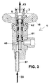
- FIG. 1 shows a sectional view of a fitting 1 for a gas cylinder.
- a gas tap 2 with an external thread, which protrudes laterally and that horizontally from a standing gas cylinder, not shown, when the valve 1 is intended to be connected to a gas cylinder.
- the line of a gas consumer such as a gas grill, be screwed to remove gas.
- the funnel-shaped opening 3 serves as a centric filling and suction.
- the funnel-shaped junction or opening 3 is connected to a filling head or suction head of a gas filling station.
- An externally accessible upper region of the outer wall of the centric filling point has two circumferential grooves 4, in order to enable a form-fitting clasping with complementary shaped grippers of a filling head or suction head. It can thus be created during the filling or during the suction of gas, a positive connection between the outer wall with the grooves 4 and a suction head or filling head to prevent unplanned disengagement of a head during filling or emptying of a gas cylinder.
- a sealing ring 5 is held by a corresponding circumferential groove in the funnel-shaped opening 3. A filling head or suction head is pressed against this sealing ring 5 during filling or emptying.
- a hollow-cylindrical valve body 6 has in a lower region a sealing ring 7 which is held in a corresponding circumferential groove of the valve body 6.
- the valve body 6 is biased in the direction of the opening 4.
- the sealing ring 7 is pressed against a cone-shaped transition 9 for closing the valve.
- the access via the opening 4 in the fitting 1 is then, as in the FIG. 1 shown, gas-tight and liquid-tight closed and indeed more reliable and durable compared to that from the document DE 43 34 182 A1 known ball valve of the centric filling point. In the case of leakage of the valve due to fatigue, it is sufficient to replace only the sealing ring 9 regularly.
- valve body 6 is in the closed state of the valve as in the FIG. 1 shown predominantly in a tubular portion 10 whose inner diameter corresponds to the outer diameter of the valve body 6. The valve body 6 is therefore guided through this tubular portion 10.
- the spring 8 is located in a widened tubular portion 10.
- the tubular portion 10 is connected by the cone-shaped transition 9 with a comparatively widened tubular portion 11.
- the inner diameter of the widened portion 11 is slightly larger than the diameter of the spring 8.
- the widened portion 11 is therefore u. a. the stop and the guidance of the spring 8, if this is further stretched to open the valve.
- the hollow cylindrical valve body 6 is closed at the lower end with a rod 12.
- the rod 12 extends into a cylinder 13.
- the inner diameter of the cylinder 13 is greater than the outer diameter of the rod 12, so that a clearance 14 between the cylinder 13 and the rod 12 remains.
- the rod 12 opposite end of the hollow cylindrical valve body 6 is open.
- the valve body 6 in the vicinity of the rod 12 has lateral openings 15, which are gas-conductively connected to its interior or lead into its interior. If the valve body 6 is pressed by a fluid pressure or mechanically down until the lateral openings 15 pass into the widened portion 11, so the valve is open.
- the open state of the valve show the Figures 2 and 3 ,
- FIG. 1 shows the closed position of the cylinder 13.
- a sealing ring 17 at the lower end of the cylinder 13 is then pressed against a slope 18 for a closure. This closure is canceled by the cylinder by corresponding rotation of the rotary handle 16 is moved upward.
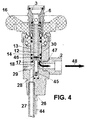
- the FIG. 4 shows the open position of the cylinder 13th
- the cylinder 13 is sealed by sealing rings 19 against a portion 21 of the housing wall of the valve 1.
- cylinder 13 is sealed by sealing rings 20 against a cylindrical lower portion 22 of the rotary handle 16.
- the sealing rings 19 and 20 prevent gas leakage from the valve out.
- the rotary handle 16 is rotatably supported by a ball bearing 23.
- a cap 24 is screwed onto the housing portion 21 so as to rotatably connect the rotary handle 16 to the housing portion 21.
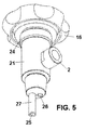
- the fitting 1 has at the bottom two openings 25 and 26 (see in particular also the three-dimensional representation of FIG. 5 ). This underside is located in the gas cylinder or bottleneck if the valve is connected to a gas cylinder as intended.
- the opening 25 is located at the bottom of a tubular or tubular conduit 27 at the bottom of a correspondingly connected gas cylinder.
- the gas cylinder is filled after opening the valve with the valve body 6 with gas or sucked liquid gas.
- the removal of gas from the bottle takes place for consumption by a consumer connected to the gas tap 2, specifically following an opening of the gas tap by corresponding rotation of the rotary handle 16.
- the opening 26 is gas-conductively connected to an inner opening 28.
- FIG. 1 shows the case that the fitting 1 is closed. Sucking or filling is not possible because the valve is closed. A gas removal via the gas tap 2 is not possible, since this is prevented by pressing the sealing ring 17 against the slope 18, the gas tap is thus closed.
- FIG. 2 illustrates the filling on the valve 1.
- the side nozzle 2 is closed and the funnel-shaped opening 4 connected to a filling head, not shown, which is pressed against the sealing ring 5 in the funnel-shaped opening 3 liquid-tight.
- the in the FIG. 1 shown opening 28 closed.
- a gas-conducting connection between the gas tap and the bottom opening 26 is interrupted.
- It will now liquefied gas according to of the arrow 33 is pumped into the funnel-shaped opening 3.
- the valve body 6 is pressed down until the hollow cylindrical portion 29 is pressed against the sealing ring 31.
- the lateral openings 15 of the valve body 6 are now in the widened tubular portion 11.
- the liquid gas pumped along the arrow 33 can now escape from the openings 15 of the valve body 6 and indeed in the widened tubular portion 11 inside.
- the liquefied gas may flow around the lower portion of the valve body 6, as indicated by the arrows 34.
- the liquefied gas flows into the space 14 between the rod 12 and the housing portion 21 and thus enters the tubular or tubular conduit 27 as indicated by the arrows 35 and 36.
- the liquid gas then exits the valve 1 as indicated by arrow 37 and thus reaches the bottom of a gas cylinder, not shown, to which the valve 1 is attached.
- FIG. 2 illustrates that the hollow cylindrical portion 29 has a smaller outer diameter 38 in an upper region, so as to be in the case of FIG. 2 to provide such a distance to the adjacent housing inner wall such that a gas flow according to the arrow 36 is possible.
- valve body 6 For sucking off or emptying, the valve body 6 is pressed down mechanically by means of a spike or socket of a suction head placed on the funnel 3. Following this, liquefied gas can be sucked off, according to the arrows 39 to 43, as in FIG. 3 shown. Since due to the tube or tube 27 is sucked from the ground, it is ensured that liquefied gas is removed and no gaseous atmosphere above the liquid level in the gas cylinder. A liquefied gas cylinder can therefore be pumped out particularly quickly and with little effort.
- FIG. 4 shows the valve 1 in the open state of the gas tap 2 and in the closed state of the valve.
- the gas cock 2 is opened because the valve body 6 is in its closed position and the cylinder 13 is moved by rotating the unit 16 upwards and therefore the sealing ring 17 has been removed from the slope 18.
- the gas which is located above the liquid level in the LPG bottle, can now enter the opening 26 according to the arrow 44 and flow to the inner opening 28. From the opening 28, the gas passes according to the arrow 45 in the interior of the hollow cylindrical portion 29. The gas then exits through the opening 30 at the upper end of the hollow cylindrical portion 29 and passes in accordance with the arrow 46 into the space 14 inside. Since a distance between the sealing ring 17 and the slope 18 is present, the gas according to the arrow 47 can flow further into the nozzle of the gas tap 2 and be forwarded from here according to the arrow 48 to the consumer.
- the method for refilling also provides for draining in the event that a gas leak is detected. Especially the emptying can be done very quickly, since liquid is pumped and not gas.
Landscapes
- Engineering & Computer Science (AREA)
- Mechanical Engineering (AREA)
- General Engineering & Computer Science (AREA)
- Filling Or Discharging Of Gas Storage Vessels (AREA)
- Lift Valve (AREA)
Abstract
Description
- Die Erfindung betrifft eine Armatur für Flüssiggasflaschen sowie ein Verfahren für ein Wiederbefüllen mit Flüssiggas.
- Eine Gasflasche ist ein in der Regel aus Metall, regelmäßig aus Stahl, bestehender Druckbehälter für den Transport und die Lagerung von unter Druck stehenden Gasen. Eine solche Flasche kann ein Volumen von mehr als 100 Litern aufweisen. Der Nenndruck kann mehrere Hundert bar betragen.
- In Flüssiggasflaschen befinden sich Gase wie zum Beispiel LPG in verflüssigter Form. Übliche Gase sind Ethan, Propan, Butan sowie Gemische davon. Diese Gase können bei Raumtemperatur durch vergleichsweise geringen Druck verflüssigt werden. Der Flüssiggasinhalt von solchen Flaschen liegt in der Regel zwischen 3 und 33 kg. Die Höhe von solchen Flüssiggasflaschen liegt meist zwischen 420 mm und 1290 mm. Der Flaschendurchmesser liegt typischerweise zwischen 200 mm und 318 mm.
- Flüssiggasflaschen werden mit einer Armatur verschlossen, an der sich, meist in Verbindung mit einem Druckminderer, eine passende Schlauchleitung zur kontrollierten Entnahme ihres Inhaltes anschrauben lässt. Des Weiteren befindet sich bei Flüssiggasflaschen in der Entnahmearmatur ein Sicherheitsventil, welches den zulässigen Überdruck in der Flasche auf zum Beispiel ca. 30 bar begrenzt, um ein Bersten zu verhindern.
- Typischerweise weist eine Armatur einer solchen Flüssiggasflasche einen seitlichen Anschlussstutzen als Gashahn auf, der einerseits zum Auffüllen und andererseits zur Entnahme verwendet wird. An diesen Gashahn werden Leitungen sowohl im Fall der Entnahme als auch im Fall einer Wiederbefüllung manuell aufgeschraubt. Der seitliche Anschlussstutzen ist bei geöffnetem Gashahn mit einer Öffnung an der Unterseite der Armatur gasleitend verbunden. Diese Unterseite mit der Öffnung befindet sich oberhalb des Flüssigkeitsspiegels im aufgestellten Zustand einer Flüssiggasflasche. Bei einer Entnahme von Gas wird daher das Gas entnommen, welches sich oberhalb des Flüssigkeitsspiegels im gasförmigen Zustand befindet.
- Flüssiggasflaschen werden für den Betrieb von Gasherden, Gaskochern, Gasgrills, Gasheizöfen oder Gasheizstrahlern eingesetzt. Ist der Inhalt einer Flüssiggasflasche verbraucht, so werden Flüssiggasflaschen vom Verbraucher an die Verkaufsstelle von Flüssiggasflaschen zwecks erneuter Auffüllung zurückgegeben. Nach einer solchen Rückgabe einer Flüssiggasflasche wird diese von der Verkaufsstelle zu einer zentralen Abfüllanlage bzw. Abfüllstation transportiert.
- Um eine Wiederbefüllung zu erleichtern, ist aus der Druckschrift
DE 43 34 182 A1 bekannt, zusätzlich zu einem seitlichen Anschlussstutzen bzw. seitlichen Gashahn eine zentrische Befüllstelle vorzusehen. Eine Befüllung kann dann von oben erfolgen, ohne dass ein Ausrichten eines seitlich abstehenden Gashahns erforderlich wäre. - Es ist Aufgabe der Erfindung, den technischen Aufwand für ein Wiederbefüllen von Gasflaschen zu verringern.
- Die Aufgabe der Erfindung wird durch eine Armatur mit den Merkmalen des Hauptanspruchs gelöst. Vorteilhafte Ausgestaltungen ergeben sich aus den abhängigen Ansprüchen. Ein vorteilhaftes Verfahren für ein Wiederbefüllen umfasst die Merkmale des Nebenanspruchs.
- Eine anspruchsgemäße Armatur umfasst zur Lösung der Aufgabe einen Gashahn für eine Gasentnahme und einer Öffnung für ein Wiederbefüllen einer Flüssiggasflasche. Die Öffnung für ein Wiederbefüllen einer Flüssiggasflasche kann insbesondere durch Öffnen eines Ventils mit einer schlauchförmigen oder rohrförmigen Leitung der Armatur gasleitend verbunden werden, die wenigstens 300 mm, vorzugsweise wenigstens 400 mm, in eine Flüssiggasflasche hineinreichen kann, wenn die Armatur mit einer solchen Gasflasche verbunden ist. Hierdurch wird erreicht, dass die Leitung in den verflüssigten Teil des Gases hineinreichen kann, was vor allem ein sehr schnelles Entleeren durch Abpumpen ermöglicht. Ein Entleeren ist geboten, wenn sich eine wiederbefüllte Gasflasche als undicht erweist. Es ergibt sich so ein Geschwindigkeitsvorteil.
- Grundsätzlich gibt es eine Öffnung an der Unterseite der Armatur benachbart zur schlauchförmigen oder rohrförmigen Leitung. Die Unterseite ist die Seite, die an die Flüssiggasflasche angrenzt bzw. sich vollständig in der Flasche oder im Flaschenhals befindet, wenn die Armatur mit einer Flüssiggasflasche verbunden ist. Diese Öffnung an der Unterseite kann mit dem Gashahn gasleitend verbunden werden, und zwar in der Regel durch Drehen eines entsprechenden Drehgriffs. Die schlauchförmige oder rohrförmige Leitung steht gegenüber dieser Öffnung vor und zwar vorzugsweise wenigstens um 200 mm, besonders bevorzugt wenigstens um 300 mm.
- Hierdurch wird erreicht, dass Gas oberhalb des Flüssigkeitsspiegels über den Gashahn entnommen werden kann und damit sofort in der Form vorliegt, in der das Gas im Falle eines Verbrauchs benötigt wird.
- Die schlauchförmige bzw. rohrförmige Leitung ist daher vorzugsweise so lang, dass diese bis zum Grund einer mit der Armatur verbundenen Gasflasche reicht. In der Regel ist daher diese Leitung nicht länger als 1290 mm.
- Die Öffnung für ein Wiederbefüllen der Flüssiggasflasche ist vorteilhaft an der Oberseite der Armatur angeordnet. Dies erleichtert ein Wiederbefüllen, da eine Flüssiggasflasche nicht für ein Wiederbefüllen ausgerichtet werden muss. Insbesondere ist so mit geringem technischen Aufwand ein automatisches Wiederbefüllen in einer automatisierten Abfüllstation möglich.
- Der Gashahn, über den das Gas zwecks Verbrauch entnommen wird, steht vorzugsweise seitlich von der Armatur ab. Durch einen Drehgriff bzw. Handrad kann der Gashahn vorzugsweise geöffnet und geschlossen werden. Das Handrad ist vorteilhaft um die Zuführung für ein Wiederbefüllen herum angeordnet. Über das Handrad wird zum Beispiel eine Mutter mit Spindel betätigt und zwar derart, dass ein dafür vorgesehener Körper hoch und runter bewegt werden kann. Hierdurch wird der Gashahn geöffnet oder geschlossen.
- Die Öffnung für ein Wiederbefüllen einer Flüssiggasflasche kann in einer Ausgestaltung durch ein Ventil geöffnet und geschlossen werden. Dies erleichtert und beschleunigt ein Wiederbefüllen, da ein Flüssigkeitsdruck genügen kann, um das Ventil für ein Wiederbefüllen zu öffnen.
- Das Ventil umfasst vorzugsweise einen Ventilkörper, der durch eine vorgespannte Feder in seine geschlossene Ventilstellung gedrückt wird. Dies trägt dazu bei, allein durch einen Flüssigkeitsdruck das Ventil für ein Wiederbefüllen öffnen zu können. Außerdem wird eine Entleerung durch Abpumpen erleichtert, da das Ventil durch einen Stutzen oder einen Dorn eines Absaugkopfes dadurch geöffnet werden kann, in dem der Absaugkopf mit der dafür vorgesehenen Öffnung verbunden wird. Im Anschluss daran kann sofort abgesaugt werden, was eine automatisierte Wiederbefüllung möglich macht, die selbst durch einen Endverbraucher unter Berücksichtigung eines dann erforderlichen erhöhten Sicherheitsaufwands vorgenommen werden kann.
- Der Ventilkörper ist vorzugsweise ein Hohlzylinder ist, der seitliche Öffnungen umfasst. Der Ventilkörper kann dann vorteilhaft ein Teil der Leitung sein, über die Flüssigkeitsgas in die Flasche für ein Wiederbefüllen hineingeleitet wird oder über die Flüssigkeitsgas für ein Entleeren abgesaugt wird.
- Der Ventilkörper ist vorzugsweise mit einem umlaufenden, austauschbaren Dichtring versehen, der das Ventil im geschlossenen Zustand flüssigkeits- und gasdicht verschließt. Im Fall einer Undichtigkeit genügt in der Regel der Austausch des Dichtrings, um die Funktionstüchtigkeit der Armatur wieder herzustellen.
- Der Dichtring ist in einer vorteilhaften Ausgestaltung im geschlossenen Zustand des Ventils gegen einen konusförmigen Übergang gepresst, der einen rohrförmigen Abschnitt mit einem dem gegenüber verbreiterten rohrförmigen Abschnitt verbindet. Diese Ausgestaltung ermöglicht es, die beiden rohrförmigen Abschnitte als Zuleitung zu verwenden, um so kompakt mit geringem technischen Aufwand herstellen zu können.
- In einer Ausgestaltung ist ein Schließelement, insbesondere in der Form eines hohlzylinderförmigen Abschnitts, vorhanden, welches eine gasleitende Verbindung zwischen dem Gashahn und der Öffnung an der Unterseite der Armatur, in die Gas einer angeschlossenen Flüssiggasflasche hineinströmen kann, unterbricht, wenn der Ventilkörper in seine geöffnete Stellung bewegt wird. Hierdurch wird im Fall einer Entleerung durch Abpumpen erreicht, dass Flüssigkeit abgepumpt wird und nicht etwa Gas, was die Entleerung verzögern würde.
- Der hohlzylinderförmige Abschnitt ist vorzugsweise ein Abschnitt der Leitung, die den Gashahn mit einer Öffnung an der Unterseite der Armatur verbindet, in die Gas einer angeschlossenen Flüssiggasflasche hineinströmen kann. Dies verringert den technischen Aufwand einer Herstellung und ermöglicht ebenfalls eine kompakte Bauweise.
- Die Öffnung für ein Wiederbefüllen einer Flüssiggasflasche ist vorzugsweise trichterförmig, um ein Verbinden mit einem Befüllungskopf oder Absaugkopf durch Zentrierung zu erleichtern.
- Vorteilhaft ist die Armatur so konstruiert, dass entweder Gas über den Gashahn entnommen werden kann oder aber eine Wiederbefüllung oder Entleerung über die dafür vorgesehene Öffnung erfolgen kann. Es kann dann nicht gleichzeitig wiederbefüllt werden und zugleich über den Gashahn Gas entnommen werden. Dies vermeidet Risiken während einer Gasentnahme oder während eines Wiederbefüllens.
- In einer Ausgestaltung der Erfindung gibt es eine weitere Gasentnahmemöglichkeit vorzugsweise über eine Schnellkopplung. An diese weitere Gasentnahmemöglichkeit kann zum Beispiel ein Schlauch angeschlossen werden und zwar zur dauerhaften, grundsätzlich nicht regulierbaren Gasentnahme. Diese zusätzliche Gasentnahmemöglichkeit ist für Ballonfahrer vorgesehen, um eine Flamme dauerhaft mit Gas versorgen zu können. Diese Flamme dient beispielsweise als Zündflamme. Diese Flamme benötigt grundsätzlich nur wenig Gas. Es wird so z. B. verhindert, dass übermäßig viel Gas durch ein zu weit aufgedrehtes Handrad für die Zündflamme verbraucht werden kann. Ist eine Schnellkopplung vorgesehen, so kann die Gasentnahme nur durch Anschließen eines entsprechenden Kupplungsstücks ermöglicht werden. Ein versehentliches Öffnen wird so verhindert.
- In einer Ausgestaltung gibt es eine Berstsicherung, die bei übermäßig hohem Innendruck zerstört wird, um so Gas kontrolliert austreten zu lassen und so einen zu hohen Innendruck zu reduzieren.
- Nachfolgend wird die Erfindung anhand von Figuren näher erläutert.
- Es zeigen:
- Figur 1:
- Armatur mit geschlossenem Gashahn und geschlossenem Ventil;
- Figur 2:
- Armatur mit geschlossenem Gashahn und geöffnetem Ventil;
- Figur 3:
- Armatur mit geschlossenem Gashahn und geöffnetem Ventil;
- Figur 4:
- Armatur mit geöffnetem Gashahn und geschlossenem Ventil;
- Figur 5:
- Armatur in einer dreidimensionalen Darstellung.
- Die
Figur 1 zeigt in einer Schnittdarstellung eine Armatur 1 für eine Gasflasche. Es gibt einen Gashahn 2 mit einem Außengewinde, der seitlich absteht und zwar horizontal von einer stehenden nicht dargestellten Gasflasche, wenn die Armatur 1 bestimmungsgemäß mit einer Gasflasche verbunden ist. Auf den Gashahn 2 kann die Leitung eines Gasverbrauchers, so zum Beispiel eines Gasgrills, zur Entnahme von Gas aufgeschraubt werden. - Zusätzlich zu dem seitlich abstehenden Stutzen 2 gibt es an der Oberseite eine trichterförmige Öffnung 3 in die Armatur 1 hinein. Die nach oben führende trichterförmige Öffnung 3 dient als zentrische Befüllungs- und Absaugstelle. Für ein Befüllen oder Absaugen wird die trichterförmige Einmündung bzw. Öffnung 3 mit einem Befüllungskopf oder Absaugkopf einer Gasabfüllstation verbunden.
- Ein von außen zugänglicher oberer Bereich der Außenwand der zentrischen Befüllungsstelle weist zwei umlaufende Rillen 4 auf, um ein formschlüssiges Umklammern mit komplementär geformten Greifern eines Befüllungskopfes oder Absaugkopfes zu ermöglichen. Es kann so während des Befüllens oder während des Absaugens von Gas eine formschlüssige Verbindung zwischen der Außenwand mit den Rillen 4 und einem Absaugkopf oder Befüllungskopf geschaffen werden, um ein unplanmäßiges Lösen eines Kopfes während des Füllens oder Entleerens einer Gasflasche zu verhindern.
- Um eine dichte Verbindung während des Füllens oder Entleerens zu gewährleisten, wird ein Dichtring 5 durch eine entsprechende umlaufende Rille in der trichterförmige Öffnung 3 gehalten. Ein Befüllungskopf bzw. Absaugkopf wird während des Füllens oder Entleerens gegen diesen Dichtring 5 gepresst.
- Ein hohlzylinderförmiger Ventilkörper 6 weist in einem unteren Bereich einen Dichtring 7 auf, der in einer entsprechenden umlaufenden Nut des Ventilkörpers 6 gehalten wird. Durch eine Feder 8 wird der Ventilkörper 6 in Richtung der Öffnung 4 vorgespannt. Hierdurch wird der Dichtring 7 gegen einen konusförmigen Übergang 9 für ein Verschließen des Ventils gepresst. Der Zugang über die Öffnung 4 in die Armatur 1 hinein ist dann, wie in der
Figur 1 gezeigt, gasdicht und flüssigkeitsdicht verschlossen und zwar zuverlässiger und dauerhafter im Vergleich zu dem aus der DruckschriftDE 43 34 182 A1 bekannten Kugelventil der zentrischen Befüllungsstelle. Im Fall einer Undichtigkeit des Ventils aufgrund von Ermüdungserscheinungen genügt es regelmäßig, lediglich den Dichtring 9 auszutauschen. - Der Ventilkörper 6 befindet sich im geschlossenen Zustand des Ventils wie in der
Figur 1 gezeigt überwiegend in einem rohrförmigen Abschnitt 10, dessen Innendurchmesser dem Außendurchmesser des Ventilkörpers 6 entspricht. Der Ventilkörper 6 wird daher durch diesen rohrförmigen Abschnitt 10 geführt. - Die Feder 8 befindet sich in einem demgegenüber verbreiterten rohrförmigen Abschnitt 10. Der rohrförmige Abschnitt 10 wird durch den konusförmigen Übergang 9 mit einem im Vergleich dazu verbreiterten rohrförmigen Abschnitt 11 verbunden. Der Innendurchmesser des verbreiterten Abschnitts 11 ist geringfügig größer als der Durchmesser der Feder 8. Der verbreiterte Abschnitt 11 dient daher u. a. dem Halt und der Führung der Feder 8, wenn diese für ein Öffnen des Ventils weiter gespannt wird.
- Der hohlzylinderförmige Ventilkörper 6 ist am unteren Ende mit einem Stab 12 verschlossen. Der Stab 12 erstreckt sich in einen Zylinder 13 hinein. Der Innendurchmesser des Zylinders 13 ist größer als der Außendurchmesser des Stabs 12, so dass ein Freiraum 14 zwischen dem Zylinder 13 und dem Stab 12 verbleibt.
- Das dem Stab 12 gegenüberliegende Ende des hohlzylinderförmigen Ventilkörpers 6 ist offen. Darüber hinaus weist der Ventilkörper 6 in der Nähe des Stabs 12 seitliche Öffnungen 15 auf, die mit seinem Innenraum gasleitend verbunden sind bzw. in seinen Innenraum hineinführen. Wird der Ventilkörper 6 durch einen Flüssigkeitsdruck oder aber mechanisch nach unten gedrückt, bis die seitliche Öffnungen 15 in den verbreiterten Abschnitt 11 hinein gelangen, so ist das Ventil geöffnet. Den geöffneten Zustand des Ventils zeigen die
Figuren 2 und3 . - Um den seitlichen Stutzen 2 zu öffnen und zu verschließen, gibt es einen Drehgriff 16, auch Handrad genannt. Durch entsprechendes Drehen des Drehgriffs bzw. Handrads 16 kann der Zylinder 13 zwischen einer Schließstellung und einer Offenstellung hin und zurück bewegt werden. Die
Figur 1 zeigt die Schließstellung des Zylinders 13. Ein Dichtring 17 am unteren Ende des Zylinders 13 ist dann gegen eine Schräge 18 für ein Verschließen gepresst. Dieser Verschluss wird aufgehoben, indem der Zylinder durch entsprechendes Drehen des Drehgriffs 16 nach oben bewegt wird. DieFigur 4 zeigt die Offenstellung des Zylinders 13. - Der Zylinder 13 ist durch Dichtringe 19 gegenüber einem Abschnitt 21 der Gehäusewand der Armatur 1 abgedichtet. Darüber hinaus ist Zylinder 13 durch Dichtringe 20 gegenüber einem zylinderförmigen unteren Abschnitt 22 des Drehgriffs 16 abgedichtet. Die Dichtringe 19 und 20 verhindern einen Gasaustritt aus der Armatur heraus.
- Der Drehgriff 16 ist durch eine Kugellagerung 23 drehbar gehalten. Eine Kappe 24 ist auf dem Gehäuseabschnitt 21 aufgeschraubt, um so den Drehgriff 16 mit dem Gehäuseabschnitt 21 drehbar zu verbinden.
- Die Armatur 1 weist an der Unterseite zwei Öffnungen 25 und 26 auf (siehe insbesondere auch die dreidimensionale Darstellung der
Figur 5 ). Diese Unterseite befindet sich in der Gasflasche bzw. im Flaschenhals, wenn die Armatur mit einer Gasflasche bestimmungsgemäß verbunden ist. - Die Öffnung 25 befindet sich am unteren Ende einer schlauchförmigen bzw. rohrförmigen Leitung 27 am Grund einer entsprechend angeschlossenen Gasflasche. Über diese Öffnung 25 wird die Gasflasche im Anschluss an ein Öffnen des Ventils mit dem Ventilkörper 6 mit Gas befüllt oder Flüssiggas abgesaugt. Über die andere Öffnung 26 erfolgt die Entnahme von Gas aus der Flasche für einen Verbrauch durch einen an den Gashahn 2 angeschlossenen Verbraucher und zwar im Anschluss an ein Öffnen des Gashahns durch entsprechendes Drehen des Drehgriffs 16.
- Die Öffnung 26 ist gasleitend mit einer inneren Öffnung 28 verbunden.
- An das untere Ende des Stabes 12 schließt sich ein damit verbundener hohlzylinderförmiger Abschnitt 29 an, der im Übergangsbereich zwischen Stab 12 und Abschnitt 29 mit einer Öffnung 30 versehen ist. Wird der Ventilkörper 6 nach unten gedrückt, so wird der hohlzylinderförmige Abschnitt 29 gegen einen Dichtring 31 gepresst, der sich am unteren Ende einer Führung 32 befindet.
- Die
Figur 1 zeigt den Fall, dass die Armatur 1 geschlossen ist. Ein Absaugen oder Befüllen ist nicht möglich, da das Ventil geschlossen ist. Eine Gasentnahme über den Gashahn 2 ist nicht möglich, da dies durch Pressen des Dichtrings 17 gegen die Schräge 18 verhindert wird, der Gashahn also verschlossen ist. - Die
Figur 2 verdeutlicht das Befüllen über die Armatur 1. Der seitliche Stutzen 2 ist verschlossen und die trichterförmige Öffnung 4 mit einem nicht dargestellten Befüllungskopf verbunden, der gegen den Dichtring 5 in der trichterförmigen Öffnung 3 flüssigkeitsdicht gepresst ist. Hierdurch wird die in derFigur 1 gezeigte Öffnung 28 verschlossen. Eine gasleitende Verbindung zwischen Gashahn und der an der Unterseite befindlichen Öffnung 26 ist so unterbrochen. Es wird nun Flüssiggas gemäß des Pfeils 33 in die trichterförmige Öffnung 3 hineingepumpt. Hierdurch wird der Ventilkörper 6 nach unten gedrückt, bis der hohlzylinderförmige Abschnitt 29 gegen den Dichtring 31 gepresst ist. Die seitlichen Öffnungen 15 des Ventilkörpers 6 befinden sich nun im verbreiterten rohrförmigen Abschnitt 11. Das entlang des Pfeils 33 hineingepumpte Flüssiggas kann nun aus den Öffnungen 15 des Ventilkörpers 6 austreten und zwar in den verbreiterten rohrförmigen Abschnitt 11 hinein. Innerhalb des verbreiterten rohrförmigen Abschnitts 11 kann das Flüssiggas um den unteren Abschnitt des Ventilkörpers 6 herum strömen, wie die Pfeile 34 verdeutlichen. Von dem verbreiterten rohrförmigen Abschnitt 11 strömt das Flüssiggas in den Zwischenraum 14 zwischen Stab 12 und Gehäuseabschnitt 21 hinein und gelangt so wie durch die Pfeile 35 und 36 dargestellt in die rohrförmige oder schlauchförmige Leitung 27 hinein. Am unteren Ende der rohrförmigen oder schlauchförmigen Leitung 27 tritt das Flüssiggas dann gemäß Pfeil 37 aus der Armatur 1 aus und gelangt so zum Grund einer nicht gezeigten Gasflasche, an der die Armatur 1 befestigt ist. - Die
Figur 2 verdeutlicht, dass der hohlzylinderförmige Abschnitt 29 in einem oberen Bereich einen geringeren Außendurchmesser 38 aufweist, um so im Fall derFigur 2 einen solchen Abstand zu der angrenzenden Gehäuseinnenwand derart zu schaffen, dass ein Gasfluss gemäß dem Pfeil 36 möglich ist. - Für ein Absaugen oder Entleeren wird der Ventilkörper 6 mechanisch durch einen Dorn oder Stutzen eines auf den Trichter 3 aufgesetzten Absaugkopfes nach unten gedrückt. Im Anschluss daran kann Flüssiggas abgesaugt werden und zwar gemäß den Pfeilen 39 bis 43, wie in der
Figur 3 gezeigt. Da aufgrund des Schlauches bzw. Rohrs 27 vom Grund abgesaugt wird, wird so sichergestellt, dass verflüssigtes Gas entnommen wird und keine gasförmige Atmosphäre oberhalb des Flüssigkeitsspiegels in der Gasflasche. Eine Flüssiggasflasche kann daher besonders schnell und mit geringem Aufwand leergepumpt werden. - Die
Figur 4 zeigt die Armatur 1 im geöffneten Zustand des Gashahns 2 und im geschlossenen Zustand des Ventils. Der Gashahn 2 ist geöffnet, weil sich der Ventilkörper 6 in seiner geschlossenen Stellung befindet und der Zylinder 13 durch Drehen des Referats 16 nach oben bewegt und daher der Dichtring 17 von der Schräge 18 entfernt worden ist. Das Gas, welches sich oberhalb des Flüssigkeitsspiegels in der Flüssiggasflasche befindet, kann nun gemäß dem Pfeil 44 in die Öffnung 26 eintreten und zur innen liegenden Öffnung 28 strömen. Von der Öffnung 28 gelangt das Gas gemäß dem Pfeil 45 in den Innenraum des hohlzylinderförmigen Abschnitts 29. Das Gas tritt dann über die Öffnung 30 am oberen Ende des hohlzylinderförmigen Abschnitts 29 aus und gelangt gemäß der Pfeildarstellung 46 in den Zwischenraum 14 hinein. Da nun ein Abstand zwischen dem Dichtring 17 und der Schräge 18 vorhanden ist, kann das Gas gemäß der Pfeildarstellung 47 weiter in den Stutzen des Gashahns 2 hineinströmen und von hier aus gemäß dem Pfeil 48 zum Verbraucher weitergeleitet werden. - Durch eine solche Armatur wird in einer entsprechenden Ausgestaltung insbesondere vorteilhaft erreicht, dass entweder Gas über den Gashahn entnommen werden kann oder aber eine Wiederbefüllung oder Entleerung über die zentrische Öffnung 3 erfolgen kann. Es kann dann nicht gleichzeitig wieder befüllt werden und über den Gashahn Gas entnommen werden.
- Das Verfahren für ein Wiederbefüllen sieht auch ein Entleeren vor für den Fall, dass eine Gasundichtigkeit festgestellt wird. Gerade das Entleeren kann besonders schnell erfolgen, da Flüssigkeit abgepumpt wird und nicht Gas.
Claims (15)
- Armatur für eine Flüssiggasflasche mit einem Gashahn (2) für eine Gasentnahme und einer Öffnung (3) für ein Wiederbefüllen einer Flüssiggasflasche, dadurch gekennzeichnet, dass die Öffnung (3) für ein Wiederbefüllen einer Flüssiggasflasche mit einer schlauchförmigen oder rohrförmigen Leitung (27) der Armatur gasleitend verbunden werden kann, die wenigstens 300 mm, vorzugsweise wenigstens 400 mm in eine Flüssiggasflasche hineinreichen kann.
- Armatur nach Anspruch 1, gekennzeichnet durch eine Öffnung (26) an der Unterseite der Armatur benachbart zur schlauchförmigen oder rohrförmigen Leitung (27), die mit dem Gashahn (2) gasleitend verbunden werden kann, wobei die schlauchförmige oder rohrförmige Leitung (27) gegenüber der Öffnung vorsteht und zwar vorzugsweise wenigstens um 200 mm, besonders bevorzugt wenigstens um 300 mm.
- Armatur nach einem der vorhergehenden Ansprüche, dadurch gekennzeichnet, dass die Öffnung (3) für ein Wiederbefüllen der Flüssiggasflasche an der Oberseite der Armatur (1) angeordnet ist.
- Armatur nach einem der vorhergehenden Ansprüche, dadurch gekennzeichnet, dass der Gashahn (2) seitlich von der Armatur (1) absteht.
- Armatur nach einem der vorhergehenden Ansprüche, dadurch gekennzeichnet, dass durch ein Handrad (16) der Gashahn (2) geöffnet und geschlossen werden kann.
- Armatur nach einem der vorhergehenden Ansprüche, dadurch gekennzeichnet, dass die Öffnung (3) für ein Wiederbefüllen einer Flüssiggasflasche durch ein Ventil geöffnet und geschlossen werden kann.
- Armatur nach dem vorhergehenden Anspruch, dadurch gekennzeichnet, dass das Ventil einen Ventilkörper (6) umfasst, der durch eine vorgespannte Feder (8) in seine geschlossene Ventilstellung gedrückt wird.
- Armatur nach dem vorhergehenden Anspruch, dadurch gekennzeichnet, dass der Ventilkörper (6) ein Hohlzylinder ist, der seitliche Öffnungen (15) umfasst.
- Armatur nach einem der beiden vorhergehenden Ansprüche, dadurch gekennzeichnet dass der Ventilkörper (6) mit einem umlaufenden, austauschbaren Dichtring (9) versehen ist, der das Ventil im geschlossenen Zustand flüssigkeits- und gasdicht verschließt.
- Armatur nach dem vorhergehenden Anspruch, dadurch gekennzeichnet, dass der Dichtring (9) im geschlossenen Zustand des Ventils gegen einen konusförmigen Übergang (9) gepresst ist, der einen rohrförmigen Abschnitt (10) mit einem dem gegenüber verbreiterten rohrförmigen Abschnitt (11) verbindet.
- Armatur nach einem der vier vorhergehenden Ansprüche, dadurch gekennzeichnet dass ein Schließelement, insbesondere in der Form eines hohlzylinderförmigen Abschnitts (29), vorhanden ist, welches eine gasleitende Verbindung zwischen dem Gashahn (2) und der Öffnung (26) an der Unterseite der Armatur, in die Gas einer angeschlossenen Flüssiggasflasche hineinströmen kann, unterbricht, wenn der Ventilkörper (6) in seine geöffnete Stellung bewegt wird.
- Armatur nach dem vorhergehenden Anspruch, dadurch gekennzeichnet, dass der hohlzylinderförmige Abschnitt (29) ein Abschnitt der Leitung ist, die den Gashahn (2) mit einer Öffnung (26) an der Unterseite der Armatur verbindet, in die Gas einer angeschlossenen Flüssiggasflasche hineinströmen kann.
- Armatur nach einem der vorhergehenden Ansprüche, dadurch gekennzeichnet, dass der Gashahn (2) zwingend geschlossen ist, wenn ein Ventil zur Wiederbefüllung geöffnet ist und/ oder umgekehrt das Ventil zur Wiederbefüllung zwingend geschlossen ist, wenn der Gashahn (2) geöffnet ist.
- Armatur nach einem der vorhergehenden Ansprüche, dadurch gekennzeichnet, dass eine weitere Öffnung mit Schnellkopplung vorhanden ist, über die Gas entnommen werden kann.
- Verfahren für ein Wiederbefüllen einer Flüssiggasflasche mit einer Armatur nach einem der vorhergehenden Ansprüche in einer Abfüllstation mit den Schritten:• mit ein Befüllungskopf der Abfüllstation wird mit der Öffnung (3) für ein Wiederbefüllen verbunden,• die Abfüllstation befüllt anschließend die Gasflasche mit Flüssiggas,• im Anschluss an die Befüllung überprüft die Abfüllstation einen Austritt von Gas aus der Gasflasche,• ergibt die Überprüfung, dass kein Gas aus der Gasflasche austritt, so wird die wiederbefüllte Gasflasche aus der Abfüllstation entnommen,• ergibt die Überprüfung, dass Gas aus der Flasche austritt, so entleert die Abfüllstation die Gasflasche durch Absaugen von Flüssiggas über die Öffnung, die für ein Wiederbefüllen vorgesehen ist.
Priority Applications (26)
| Application Number | Priority Date | Filing Date | Title |
|---|---|---|---|
| EP14192891.1A EP3021034B1 (de) | 2014-11-12 | 2014-11-12 | Armatur für Flüssiggasflaschen nebst Füllverfahren |
| SI201531083T SI3218642T1 (sl) | 2014-11-12 | 2015-10-28 | Armatura plinskih jeklenk za tekoči plin in polnilni postopek |
| DK15797869.3T DK3218642T3 (da) | 2014-11-12 | 2015-10-28 | Armatur til flasker til flydende gas samt påfyldningsfremgangsmåde |
| CN201580061232.0A CN107002946B (zh) | 2014-11-12 | 2015-10-28 | 用于液化气瓶的接头和填充方法 |
| MEP-2020-35A ME03634B (de) | 2014-11-12 | 2015-10-28 | Armatur für flüssiggasflaschen nebst füllverfahren |
| JP2017525523A JP6612341B2 (ja) | 2014-11-12 | 2015-10-28 | 液体ガスボトルの接続具と充填方法 |
| PL15797869T PL3218642T3 (pl) | 2014-11-12 | 2015-10-28 | Osprzęt do butli na gaz płynny i sposób napełniania |
| CA2964439A CA2964439C (en) | 2014-11-12 | 2015-10-28 | Fitting for liquid gas bottles and filling method |
| HUE15797869A HUE047970T2 (hu) | 2014-11-12 | 2015-10-28 | Szerelvény folyékony gázt tartalmazó palackhoz és eljárás annak töltéséhez |
| EA201790955A EA033994B1 (ru) | 2014-11-12 | 2015-10-28 | Арматура баллонов для сжиженного газа и способ заправки |
| RS20200167A RS59947B1 (sr) | 2014-11-12 | 2015-10-28 | Armatura za boce za tečni gas uključujući i metodu punjenja |
| KR1020177016058A KR102440912B1 (ko) | 2014-11-12 | 2015-10-28 | 액화가스 실린더의 피팅 및 충전 방법 |
| PT157978693T PT3218642T (pt) | 2014-11-12 | 2015-10-28 | Equipamento para garrafas de gás líquido e processo de enchimento |
| TN2017000132A TN2017000132A1 (en) | 2014-11-12 | 2015-10-28 | Fitting for liquid gas bottles and filling method |
| AU2015345387A AU2015345387B2 (en) | 2014-11-12 | 2015-10-28 | Fitting for liquid gas cylinders and filling method |
| ES15797869T ES2773443T3 (es) | 2014-11-12 | 2015-10-28 | Accesorio para botellas de gas licuado junto con procedimientos de llenado |
| MX2017006187A MX2017006187A (es) | 2014-11-12 | 2015-10-28 | Adaptador para botellas de gas liquido y metodo de rellenado. |
| MA052406A MA52406A (fr) | 2014-11-12 | 2015-10-28 | Armature pour bouteilles de gaz liquide ainsi que procédé de remplissage |
| EP15797869.3A EP3218642B1 (de) | 2014-11-12 | 2015-10-28 | Armatur für flüssiggasflaschen nebst füllverfahren |
| EP19210220.0A EP3660381B9 (de) | 2014-11-12 | 2015-10-28 | Armatur für flüssiggasflaschen nebst füllverfahren |
| PCT/EP2015/074950 WO2016074923A1 (de) | 2014-11-12 | 2015-10-28 | Armatur für flüssiggasflaschen nebst füllverfahren |
| MA40947A MA40947B1 (fr) | 2014-11-12 | 2015-10-28 | Armature pour bouteilles de gaz liquide et procédé de remplissage |
| US15/526,569 US10738945B2 (en) | 2014-11-12 | 2015-10-28 | Fitting for liquid gas cylinders and filling method |
| HK16112626.9A HK1224357A1 (zh) | 2014-11-12 | 2016-11-02 | 用於液化氣鋼瓶的閥門及填充方法 |
| ZA2017/02728A ZA201702728B (en) | 2014-11-12 | 2017-04-18 | Fitting for liquid gas cylinders and filling method |
| HRP20200242TT HRP20200242T1 (hr) | 2014-11-12 | 2020-02-13 | Armatura za boce za tekući plin uključujući i metodu punjenja |
Applications Claiming Priority (1)
| Application Number | Priority Date | Filing Date | Title |
|---|---|---|---|
| EP14192891.1A EP3021034B1 (de) | 2014-11-12 | 2014-11-12 | Armatur für Flüssiggasflaschen nebst Füllverfahren |
Publications (2)
| Publication Number | Publication Date |
|---|---|
| EP3021034A1 true EP3021034A1 (de) | 2016-05-18 |
| EP3021034B1 EP3021034B1 (de) | 2019-04-24 |
Family
ID=51897157
Family Applications (3)
| Application Number | Title | Priority Date | Filing Date |
|---|---|---|---|
| EP14192891.1A Active EP3021034B1 (de) | 2014-11-12 | 2014-11-12 | Armatur für Flüssiggasflaschen nebst Füllverfahren |
| EP19210220.0A Active EP3660381B9 (de) | 2014-11-12 | 2015-10-28 | Armatur für flüssiggasflaschen nebst füllverfahren |
| EP15797869.3A Active EP3218642B1 (de) | 2014-11-12 | 2015-10-28 | Armatur für flüssiggasflaschen nebst füllverfahren |
Family Applications After (2)
| Application Number | Title | Priority Date | Filing Date |
|---|---|---|---|
| EP19210220.0A Active EP3660381B9 (de) | 2014-11-12 | 2015-10-28 | Armatur für flüssiggasflaschen nebst füllverfahren |
| EP15797869.3A Active EP3218642B1 (de) | 2014-11-12 | 2015-10-28 | Armatur für flüssiggasflaschen nebst füllverfahren |
Country Status (23)
| Country | Link |
|---|---|
| US (1) | US10738945B2 (de) |
| EP (3) | EP3021034B1 (de) |
| JP (1) | JP6612341B2 (de) |
| KR (1) | KR102440912B1 (de) |
| CN (1) | CN107002946B (de) |
| AU (1) | AU2015345387B2 (de) |
| CA (1) | CA2964439C (de) |
| DK (1) | DK3218642T3 (de) |
| EA (1) | EA033994B1 (de) |
| ES (1) | ES2773443T3 (de) |
| HK (1) | HK1224357A1 (de) |
| HR (1) | HRP20200242T1 (de) |
| HU (1) | HUE047970T2 (de) |
| MA (2) | MA52406A (de) |
| ME (1) | ME03634B (de) |
| MX (1) | MX2017006187A (de) |
| PL (1) | PL3218642T3 (de) |
| PT (1) | PT3218642T (de) |
| RS (1) | RS59947B1 (de) |
| SI (1) | SI3218642T1 (de) |
| TN (1) | TN2017000132A1 (de) |
| WO (1) | WO2016074923A1 (de) |
| ZA (1) | ZA201702728B (de) |
Cited By (2)
| Publication number | Priority date | Publication date | Assignee | Title |
|---|---|---|---|---|
| EP3611423A1 (de) | 2018-08-14 | 2020-02-19 | CleanTech Swiss AG | Armatur für flüssiggasflaschen |
| WO2020035473A1 (de) | 2018-08-14 | 2020-02-20 | CleanTech Swiss AG | Armatur für flüssiggasflaschen |
Families Citing this family (6)
| Publication number | Priority date | Publication date | Assignee | Title |
|---|---|---|---|---|
| KR102159899B1 (ko) * | 2015-05-12 | 2020-09-24 | 엔테그리스, 아이엔씨. | 밸브 조립체 및 그를 포함하는 유체 저장 및 분배 패키지 |
| US11193631B2 (en) * | 2018-02-09 | 2021-12-07 | Tatsuno Corporation | Filling device |
| EP3696408B1 (de) | 2019-02-07 | 2023-06-07 | CleanTech Swiss AG | Kolbenpumpe |
| EP3693652B1 (de) | 2019-02-07 | 2023-07-12 | CleanTech Swiss AG | Abfüllstation für gasflaschen und kraftfahrzeuge |
| KR102286720B1 (ko) * | 2019-12-05 | 2021-08-06 | 주식회사 케이엘테크 | 고압가스 용기용 밸브유닛 |
| CN114517888A (zh) * | 2022-03-09 | 2022-05-20 | 浙江工业大学 | 一种基于自增强理论的站用储氢气瓶及储气瓶组 |
Citations (7)
| Publication number | Priority date | Publication date | Assignee | Title |
|---|---|---|---|---|
| FR55136E (fr) * | 1946-12-17 | 1951-06-06 | Robinet de sécurité pour gaz comprimés et liquéfiés | |
| BE508126A (fr) * | 1951-12-29 | 1952-01-15 | Lorch J | Petite bouteille de transvasement pour gaz liquefies |
| GB1172403A (en) * | 1967-04-19 | 1969-11-26 | Mini Of Technology London | Valve Systems and Containers for Liquified Gas |
| DE4334182A1 (de) | 1993-10-07 | 1995-04-13 | Flow Instr & Engineering Gmbh | Absperrvorrichtung, insbesondere Ventil |
| WO2010136161A1 (de) * | 2009-05-29 | 2010-12-02 | MAX-PLANCK-Gesellschaft zur Förderung der Wissenschaften e.V. | Verfahren und vorrichtung zur zuführung eines flüssigen gases in ein gefäss |
| WO2014053748A1 (fr) * | 2012-10-04 | 2014-04-10 | Siraga Sa | Dispositif, machine et procede d'emplissage de bouteille de gaz domestique comportant un detecteur de fuite |
| US20140326328A1 (en) * | 2013-05-02 | 2014-11-06 | Ysn Imports, Inc. | Combination valve assembly with actuatable overfill relief |
Family Cites Families (33)
| Publication number | Priority date | Publication date | Assignee | Title |
|---|---|---|---|---|
| US934037A (en) * | 1908-08-04 | 1909-09-14 | Paul Bunin | Valve-fitting for soda-water apparatus. |
| US1938036A (en) * | 1932-03-25 | 1933-12-05 | Carbide & Carbon Chem Corp | Means for removing liquid mixtures from pressure vessels |
| US2172310A (en) * | 1936-09-21 | 1939-09-05 | Phillips Petroleum Co | Self-service system for storage and utilization of fuel gases |
| US2529275A (en) * | 1947-12-13 | 1950-11-07 | Standard Oil Dev Co | Two-port valve for volatile liquid containers |
| US3589397A (en) * | 1970-01-19 | 1971-06-29 | William Wagner | Antirefill valve |
| US4077422A (en) * | 1975-11-17 | 1978-03-07 | Said Robie G. Brinkley, By Said Gerry D. Welton | Flow control means for compressed gas cylinders |
| JPS5822945Y2 (ja) | 1981-01-19 | 1983-05-16 | 昭和炭酸株式会社 | 圧力流体充填容器におけるサイホン管 |
| FR2618875B1 (fr) | 1987-07-28 | 1989-12-29 | Totalgaz Cie Fse | Machine unitaire pour controler dans un meme poste, les fuites, l'ouverture et la fermeture du robinet d'une bouteille de gaz liquefie, ainsi que le niveau de remplissage de la bouteille |
| GB2231137B (en) * | 1989-04-28 | 1992-10-28 | Air Prod & Chem | Pressure reducing valve |
| JPH05215299A (ja) | 1991-02-01 | 1993-08-24 | Neriki:Kk | ボンベバルブ |
| CN2098642U (zh) | 1991-09-10 | 1992-03-11 | 武汉中科数理科技开发公司 | 内装式民用液化石油气残液汽化装置 |
| CN2193461Y (zh) * | 1994-06-27 | 1995-03-29 | 河南省建星技术公司 | 仿液化石油气钢瓶 |
| JPH08170797A (ja) | 1994-12-20 | 1996-07-02 | Kubota Corp | 高圧ガス充填装置 |
| JPH09166293A (ja) | 1995-12-12 | 1997-06-24 | Meiko Sangyo Kk | ガス充填器 |
| JPH1061892A (ja) | 1996-08-22 | 1998-03-06 | Meiko Sangyo Kk | ガス充填機 |
| JPH10196896A (ja) | 1997-01-07 | 1998-07-31 | Aichi Koatsu Kk | 過充填防止機能付充填用ガス容器バルブ |
| JP2936480B1 (ja) | 1998-07-24 | 1999-08-23 | 原添 哲 | Lpガス充てん弁 |
| JP2979002B1 (ja) | 1998-07-24 | 1999-11-15 | 原添 哲 | Lpガス充てん弁 |
| JP4009421B2 (ja) | 2000-12-12 | 2007-11-14 | 大同テック株式会社 | ボンベの位置決め装置 |
| JP2003014193A (ja) | 2001-06-27 | 2003-01-15 | Nec Corp | シリンダキャビネット及びその配管内の残留ガスのパージ方法 |
| FR2834770B1 (fr) * | 2002-01-11 | 2004-06-25 | Gce Sas | Dispositif d'obturation utilisable dans un dispositif de robinet pour bouteille de gaz sous pression |
| US7278454B2 (en) * | 2003-03-13 | 2007-10-09 | Laminar Technologies, Llc | Beverage dispensing apparatus |
| JP2006283899A (ja) | 2005-04-01 | 2006-10-19 | Neriki:Kk | バルブ装置とガス容器および充填用接続装置 |
| CN101600644B (zh) * | 2006-07-11 | 2014-08-13 | 考尔得产品公司 | 用于容器的连接/分离联接装置 |
| US7752892B2 (en) * | 2006-09-07 | 2010-07-13 | Matheson Tri-Gas | Leak characterization apparatuses and methods for fluid storage containers |
| JP2008105699A (ja) | 2006-10-25 | 2008-05-08 | Shibuya Kogyo Co Ltd | 充填バルブ |
| US8459316B2 (en) | 2008-06-11 | 2013-06-11 | Maria Teresa Suero Castaño | Safety cabinet for filling self-contained breathing apparatus bottles |
| WO2010030921A1 (en) | 2008-09-15 | 2010-03-18 | Scott Technologies, Inc. | Method and system for filling a gas cylinder |
| US8479767B2 (en) * | 2009-11-13 | 2013-07-09 | Ysn Imports, Inc. | Combined fill and safety vent plug |
| BRPI1002740B1 (pt) | 2010-08-20 | 2020-12-29 | Flávio Camilotti | sistema compacto de envasamento de gás |
| EP2466187A1 (de) * | 2010-12-16 | 2012-06-20 | Air Products And Chemicals, Inc. | Gaslagerungsbehälter |
| ES2423107B1 (es) | 2012-02-14 | 2014-07-25 | Roberto GARCIA MEIZOSO | Vehiculo polivalente y autonomo para el suministro de gas envasado y a granel |
| CA2905380A1 (en) | 2013-03-13 | 2014-10-02 | Scott Technologies, Inc. | Base manifold and system for filling containers with gas |
-
2014
- 2014-11-12 EP EP14192891.1A patent/EP3021034B1/de active Active
-
2015
- 2015-10-28 JP JP2017525523A patent/JP6612341B2/ja active Active
- 2015-10-28 EP EP19210220.0A patent/EP3660381B9/de active Active
- 2015-10-28 RS RS20200167A patent/RS59947B1/sr unknown
- 2015-10-28 TN TN2017000132A patent/TN2017000132A1/en unknown
- 2015-10-28 MA MA052406A patent/MA52406A/fr unknown
- 2015-10-28 WO PCT/EP2015/074950 patent/WO2016074923A1/de active Application Filing
- 2015-10-28 MX MX2017006187A patent/MX2017006187A/es unknown
- 2015-10-28 EP EP15797869.3A patent/EP3218642B1/de active Active
- 2015-10-28 KR KR1020177016058A patent/KR102440912B1/ko active IP Right Grant
- 2015-10-28 MA MA40947A patent/MA40947B1/fr unknown
- 2015-10-28 AU AU2015345387A patent/AU2015345387B2/en active Active
- 2015-10-28 ES ES15797869T patent/ES2773443T3/es active Active
- 2015-10-28 CA CA2964439A patent/CA2964439C/en active Active
- 2015-10-28 DK DK15797869.3T patent/DK3218642T3/da active
- 2015-10-28 SI SI201531083T patent/SI3218642T1/sl unknown
- 2015-10-28 US US15/526,569 patent/US10738945B2/en active Active
- 2015-10-28 EA EA201790955A patent/EA033994B1/ru unknown
- 2015-10-28 HU HUE15797869A patent/HUE047970T2/hu unknown
- 2015-10-28 PT PT157978693T patent/PT3218642T/pt unknown
- 2015-10-28 PL PL15797869T patent/PL3218642T3/pl unknown
- 2015-10-28 CN CN201580061232.0A patent/CN107002946B/zh active Active
- 2015-10-28 ME MEP-2020-35A patent/ME03634B/de unknown
-
2016
- 2016-11-02 HK HK16112626.9A patent/HK1224357A1/zh unknown
-
2017
- 2017-04-18 ZA ZA2017/02728A patent/ZA201702728B/en unknown
-
2020
- 2020-02-13 HR HRP20200242TT patent/HRP20200242T1/hr unknown
Patent Citations (7)
| Publication number | Priority date | Publication date | Assignee | Title |
|---|---|---|---|---|
| FR55136E (fr) * | 1946-12-17 | 1951-06-06 | Robinet de sécurité pour gaz comprimés et liquéfiés | |
| BE508126A (fr) * | 1951-12-29 | 1952-01-15 | Lorch J | Petite bouteille de transvasement pour gaz liquefies |
| GB1172403A (en) * | 1967-04-19 | 1969-11-26 | Mini Of Technology London | Valve Systems and Containers for Liquified Gas |
| DE4334182A1 (de) | 1993-10-07 | 1995-04-13 | Flow Instr & Engineering Gmbh | Absperrvorrichtung, insbesondere Ventil |
| WO2010136161A1 (de) * | 2009-05-29 | 2010-12-02 | MAX-PLANCK-Gesellschaft zur Förderung der Wissenschaften e.V. | Verfahren und vorrichtung zur zuführung eines flüssigen gases in ein gefäss |
| WO2014053748A1 (fr) * | 2012-10-04 | 2014-04-10 | Siraga Sa | Dispositif, machine et procede d'emplissage de bouteille de gaz domestique comportant un detecteur de fuite |
| US20140326328A1 (en) * | 2013-05-02 | 2014-11-06 | Ysn Imports, Inc. | Combination valve assembly with actuatable overfill relief |
Cited By (5)
| Publication number | Priority date | Publication date | Assignee | Title |
|---|---|---|---|---|
| EP3611423A1 (de) | 2018-08-14 | 2020-02-19 | CleanTech Swiss AG | Armatur für flüssiggasflaschen |
| WO2020035473A1 (de) | 2018-08-14 | 2020-02-20 | CleanTech Swiss AG | Armatur für flüssiggasflaschen |
| KR20210043564A (ko) * | 2018-08-14 | 2021-04-21 | 크린테크 스위스 아게 | 액체 가스통을 위한 피팅 |
| RU2763244C1 (ru) * | 2018-08-14 | 2021-12-28 | Клинтек Свисс Аг | Запорно-регулирующее устройство для баллонов для сжиженного газа |
| US11808408B2 (en) | 2018-08-14 | 2023-11-07 | CleanTech Swiss AG | Fitting for liquid gas bottles |
Also Published As
Similar Documents
| Publication | Publication Date | Title |
|---|---|---|
| EP3218642B1 (de) | Armatur für flüssiggasflaschen nebst füllverfahren | |
| DE2264061A1 (de) | Druckgefaess fuer fluessiggas | |
| EP0787099B1 (de) | Einrichtung zur belüftung eines flüssigkeitsbehälters | |
| DE1432408B2 (de) | Vorrichtung zum Sterilisieren und Füllen von Flüssigkeitsbehältern | |
| DE102008024579B4 (de) | Behälter | |
| DE10040336A1 (de) | Ventilschutzkappe für Druckgasbehälter | |
| EP3611423B1 (de) | Armatur für flüssiggasflaschen | |
| DE3901422C1 (en) | Filling and emptying device for a pressurised container | |
| DE149990C (de) | ||
| DE202018106076U1 (de) | Armatur für Flüssiggasflaschen | |
| WO2020035473A1 (de) | Armatur für flüssiggasflaschen | |
| DE693870C (de) | Vorrichtung zum Anschliessen von Behaeltern an Fuellanlagen fuer unter Druck stehende verfluessigte Gase | |
| DE19725486C1 (de) | Dosiereinrichtung | |
| EP3366918A1 (de) | Vorrichtung zum auffangen von verbrauchtem schmiermittel | |
| DE1657144A1 (de) | Spundeinsatz fuer einen Getraenketank | |
| EP2921710A1 (de) | Strömungsmaschine mit Dichtungseinheit, Wartungsverfahren sowie zugehörige Wartungsvorrichtungen | |
| DE1566592B1 (de) | Narkosemittelverdunster | |
| DE2521099A1 (de) | Druckversorgungsteil fuer aus druckdichten behaeltern zu entnehmende fluessigkeiten | |
| DE2750413A1 (de) | Ventil fuer gasbehaelter | |
| AT59192B (de) | Hahnverschluß für Transportgefäße. | |
| EP2730536B1 (de) | Zapfanordnung mit Abströmventil | |
| DE1482692C (de) | Zapfvomchtung, insbesondere fur Bierfasser | |
| DE4204660A1 (de) | Vorrichtung fuer die entnahme von unter dem druck eines druckgases stehenden fluessigkeiten aus einem behaelter | |
| EP3378829A1 (de) | Tank mit entlüftung | |
| DE1152634B (de) | Auslassvorrichtung fuer Fluessigkeiten aus Behaeltern |
Legal Events
| Date | Code | Title | Description |
|---|---|---|---|
| PUAI | Public reference made under article 153(3) epc to a published international application that has entered the european phase |
Free format text: ORIGINAL CODE: 0009012 |
|
| AK | Designated contracting states |
Kind code of ref document: A1 Designated state(s): AL AT BE BG CH CY CZ DE DK EE ES FI FR GB GR HR HU IE IS IT LI LT LU LV MC MK MT NL NO PL PT RO RS SE SI SK SM TR |
|
| AX | Request for extension of the european patent |
Extension state: BA ME |
|
| 17P | Request for examination filed |
Effective date: 20160613 |
|
| RBV | Designated contracting states (corrected) |
Designated state(s): AL AT BE BG CH CY CZ DE DK EE ES FI FR GB GR HR HU IE IS IT LI LT LU LV MC MK MT NL NO PL PT RO RS SE SI SK SM TR |
|
| RAP1 | Party data changed (applicant data changed or rights of an application transferred) |
Owner name: LPG SUISSE AG |
|
| REG | Reference to a national code |
Ref country code: HK Ref legal event code: DE Ref document number: 1224357 Country of ref document: HK |
|
| RAP1 | Party data changed (applicant data changed or rights of an application transferred) |
Owner name: CLEANTECH SWISS AG |
|
| GRAP | Despatch of communication of intention to grant a patent |
Free format text: ORIGINAL CODE: EPIDOSNIGR1 |
|
| STAA | Information on the status of an ep patent application or granted ep patent |
Free format text: STATUS: GRANT OF PATENT IS INTENDED |
|
| INTG | Intention to grant announced |
Effective date: 20181206 |
|
| GRAS | Grant fee paid |
Free format text: ORIGINAL CODE: EPIDOSNIGR3 |
|
| GRAA | (expected) grant |
Free format text: ORIGINAL CODE: 0009210 |
|
| STAA | Information on the status of an ep patent application or granted ep patent |
Free format text: STATUS: THE PATENT HAS BEEN GRANTED |
|
| AK | Designated contracting states |
Kind code of ref document: B1 Designated state(s): AL AT BE BG CH CY CZ DE DK EE ES FI FR GB GR HR HU IE IS IT LI LT LU LV MC MK MT NL NO PL PT RO RS SE SI SK SM TR |
|
| REG | Reference to a national code |
Ref country code: GB Ref legal event code: FG4D Free format text: NOT ENGLISH |
|
| REG | Reference to a national code |
Ref country code: CH Ref legal event code: EP |
|
| REG | Reference to a national code |
Ref country code: AT Ref legal event code: REF Ref document number: 1124563 Country of ref document: AT Kind code of ref document: T Effective date: 20190515 Ref country code: IE Ref legal event code: FG4D Free format text: LANGUAGE OF EP DOCUMENT: GERMAN |
|
| REG | Reference to a national code |
Ref country code: DE Ref legal event code: R096 Ref document number: 502014011500 Country of ref document: DE |
|
| REG | Reference to a national code |
Ref country code: CH Ref legal event code: NV Representative=s name: VALIPAT S.A. C/O BOVARD SA NEUCHATEL, CH |
|
| REG | Reference to a national code |
Ref country code: NL Ref legal event code: MP Effective date: 20190424 |
|
| REG | Reference to a national code |
Ref country code: LT Ref legal event code: MG4D |
|
| PG25 | Lapsed in a contracting state [announced via postgrant information from national office to epo] |
Ref country code: NL Free format text: LAPSE BECAUSE OF FAILURE TO SUBMIT A TRANSLATION OF THE DESCRIPTION OR TO PAY THE FEE WITHIN THE PRESCRIBED TIME-LIMIT Effective date: 20190424 |
|
| PG25 | Lapsed in a contracting state [announced via postgrant information from national office to epo] |
Ref country code: NO Free format text: LAPSE BECAUSE OF FAILURE TO SUBMIT A TRANSLATION OF THE DESCRIPTION OR TO PAY THE FEE WITHIN THE PRESCRIBED TIME-LIMIT Effective date: 20190724 Ref country code: FI Free format text: LAPSE BECAUSE OF FAILURE TO SUBMIT A TRANSLATION OF THE DESCRIPTION OR TO PAY THE FEE WITHIN THE PRESCRIBED TIME-LIMIT Effective date: 20190424 Ref country code: LT Free format text: LAPSE BECAUSE OF FAILURE TO SUBMIT A TRANSLATION OF THE DESCRIPTION OR TO PAY THE FEE WITHIN THE PRESCRIBED TIME-LIMIT Effective date: 20190424 Ref country code: SE Free format text: LAPSE BECAUSE OF FAILURE TO SUBMIT A TRANSLATION OF THE DESCRIPTION OR TO PAY THE FEE WITHIN THE PRESCRIBED TIME-LIMIT Effective date: 20190424 Ref country code: HR Free format text: LAPSE BECAUSE OF FAILURE TO SUBMIT A TRANSLATION OF THE DESCRIPTION OR TO PAY THE FEE WITHIN THE PRESCRIBED TIME-LIMIT Effective date: 20190424 Ref country code: AL Free format text: LAPSE BECAUSE OF FAILURE TO SUBMIT A TRANSLATION OF THE DESCRIPTION OR TO PAY THE FEE WITHIN THE PRESCRIBED TIME-LIMIT Effective date: 20190424 Ref country code: PT Free format text: LAPSE BECAUSE OF FAILURE TO SUBMIT A TRANSLATION OF THE DESCRIPTION OR TO PAY THE FEE WITHIN THE PRESCRIBED TIME-LIMIT Effective date: 20190824 Ref country code: ES Free format text: LAPSE BECAUSE OF FAILURE TO SUBMIT A TRANSLATION OF THE DESCRIPTION OR TO PAY THE FEE WITHIN THE PRESCRIBED TIME-LIMIT Effective date: 20190424 |
|
| PG25 | Lapsed in a contracting state [announced via postgrant information from national office to epo] |
Ref country code: BG Free format text: LAPSE BECAUSE OF FAILURE TO SUBMIT A TRANSLATION OF THE DESCRIPTION OR TO PAY THE FEE WITHIN THE PRESCRIBED TIME-LIMIT Effective date: 20190724 Ref country code: RS Free format text: LAPSE BECAUSE OF FAILURE TO SUBMIT A TRANSLATION OF THE DESCRIPTION OR TO PAY THE FEE WITHIN THE PRESCRIBED TIME-LIMIT Effective date: 20190424 Ref country code: PL Free format text: LAPSE BECAUSE OF FAILURE TO SUBMIT A TRANSLATION OF THE DESCRIPTION OR TO PAY THE FEE WITHIN THE PRESCRIBED TIME-LIMIT Effective date: 20190424 Ref country code: LV Free format text: LAPSE BECAUSE OF FAILURE TO SUBMIT A TRANSLATION OF THE DESCRIPTION OR TO PAY THE FEE WITHIN THE PRESCRIBED TIME-LIMIT Effective date: 20190424 Ref country code: GR Free format text: LAPSE BECAUSE OF FAILURE TO SUBMIT A TRANSLATION OF THE DESCRIPTION OR TO PAY THE FEE WITHIN THE PRESCRIBED TIME-LIMIT Effective date: 20190725 |
|
| PG25 | Lapsed in a contracting state [announced via postgrant information from national office to epo] |
Ref country code: IS Free format text: LAPSE BECAUSE OF FAILURE TO SUBMIT A TRANSLATION OF THE DESCRIPTION OR TO PAY THE FEE WITHIN THE PRESCRIBED TIME-LIMIT Effective date: 20190824 |
|
| REG | Reference to a national code |
Ref country code: DE Ref legal event code: R097 Ref document number: 502014011500 Country of ref document: DE |
|
| PG25 | Lapsed in a contracting state [announced via postgrant information from national office to epo] |
Ref country code: SK Free format text: LAPSE BECAUSE OF FAILURE TO SUBMIT A TRANSLATION OF THE DESCRIPTION OR TO PAY THE FEE WITHIN THE PRESCRIBED TIME-LIMIT Effective date: 20190424 Ref country code: EE Free format text: LAPSE BECAUSE OF FAILURE TO SUBMIT A TRANSLATION OF THE DESCRIPTION OR TO PAY THE FEE WITHIN THE PRESCRIBED TIME-LIMIT Effective date: 20190424 Ref country code: DK Free format text: LAPSE BECAUSE OF FAILURE TO SUBMIT A TRANSLATION OF THE DESCRIPTION OR TO PAY THE FEE WITHIN THE PRESCRIBED TIME-LIMIT Effective date: 20190424 Ref country code: RO Free format text: LAPSE BECAUSE OF FAILURE TO SUBMIT A TRANSLATION OF THE DESCRIPTION OR TO PAY THE FEE WITHIN THE PRESCRIBED TIME-LIMIT Effective date: 20190424 Ref country code: CZ Free format text: LAPSE BECAUSE OF FAILURE TO SUBMIT A TRANSLATION OF THE DESCRIPTION OR TO PAY THE FEE WITHIN THE PRESCRIBED TIME-LIMIT Effective date: 20190424 |
|
| PG25 | Lapsed in a contracting state [announced via postgrant information from national office to epo] |
Ref country code: IT Free format text: LAPSE BECAUSE OF FAILURE TO SUBMIT A TRANSLATION OF THE DESCRIPTION OR TO PAY THE FEE WITHIN THE PRESCRIBED TIME-LIMIT Effective date: 20190424 Ref country code: SM Free format text: LAPSE BECAUSE OF FAILURE TO SUBMIT A TRANSLATION OF THE DESCRIPTION OR TO PAY THE FEE WITHIN THE PRESCRIBED TIME-LIMIT Effective date: 20190424 |
|
| PLBE | No opposition filed within time limit |
Free format text: ORIGINAL CODE: 0009261 |
|
| STAA | Information on the status of an ep patent application or granted ep patent |
Free format text: STATUS: NO OPPOSITION FILED WITHIN TIME LIMIT |
|
| PG25 | Lapsed in a contracting state [announced via postgrant information from national office to epo] |
Ref country code: TR Free format text: LAPSE BECAUSE OF FAILURE TO SUBMIT A TRANSLATION OF THE DESCRIPTION OR TO PAY THE FEE WITHIN THE PRESCRIBED TIME-LIMIT Effective date: 20190424 |
|
| 26N | No opposition filed |
Effective date: 20200127 |
|
| PG25 | Lapsed in a contracting state [announced via postgrant information from national office to epo] |
Ref country code: SI Free format text: LAPSE BECAUSE OF FAILURE TO SUBMIT A TRANSLATION OF THE DESCRIPTION OR TO PAY THE FEE WITHIN THE PRESCRIBED TIME-LIMIT Effective date: 20190424 |
|
| PG25 | Lapsed in a contracting state [announced via postgrant information from national office to epo] |
Ref country code: MC Free format text: LAPSE BECAUSE OF FAILURE TO SUBMIT A TRANSLATION OF THE DESCRIPTION OR TO PAY THE FEE WITHIN THE PRESCRIBED TIME-LIMIT Effective date: 20190424 Ref country code: LU Free format text: LAPSE BECAUSE OF NON-PAYMENT OF DUE FEES Effective date: 20191112 |
|
| REG | Reference to a national code |
Ref country code: BE Ref legal event code: MM Effective date: 20191130 |
|
| GBPC | Gb: european patent ceased through non-payment of renewal fee |
Effective date: 20191112 |
|
| PG25 | Lapsed in a contracting state [announced via postgrant information from national office to epo] |
Ref country code: GB Free format text: LAPSE BECAUSE OF NON-PAYMENT OF DUE FEES Effective date: 20191112 Ref country code: FR Free format text: LAPSE BECAUSE OF NON-PAYMENT OF DUE FEES Effective date: 20191130 Ref country code: IE Free format text: LAPSE BECAUSE OF NON-PAYMENT OF DUE FEES Effective date: 20191112 |
|
| PG25 | Lapsed in a contracting state [announced via postgrant information from national office to epo] |
Ref country code: BE Free format text: LAPSE BECAUSE OF NON-PAYMENT OF DUE FEES Effective date: 20191130 |
|
| REG | Reference to a national code |
Ref country code: AT Ref legal event code: MM01 Ref document number: 1124563 Country of ref document: AT Kind code of ref document: T Effective date: 20191112 |
|
| PG25 | Lapsed in a contracting state [announced via postgrant information from national office to epo] |
Ref country code: AT Free format text: LAPSE BECAUSE OF NON-PAYMENT OF DUE FEES Effective date: 20191112 |
|
| PG25 | Lapsed in a contracting state [announced via postgrant information from national office to epo] |
Ref country code: CY Free format text: LAPSE BECAUSE OF FAILURE TO SUBMIT A TRANSLATION OF THE DESCRIPTION OR TO PAY THE FEE WITHIN THE PRESCRIBED TIME-LIMIT Effective date: 20190424 |
|
| PG25 | Lapsed in a contracting state [announced via postgrant information from national office to epo] |
Ref country code: HU Free format text: LAPSE BECAUSE OF FAILURE TO SUBMIT A TRANSLATION OF THE DESCRIPTION OR TO PAY THE FEE WITHIN THE PRESCRIBED TIME-LIMIT; INVALID AB INITIO Effective date: 20141112 Ref country code: MT Free format text: LAPSE BECAUSE OF FAILURE TO SUBMIT A TRANSLATION OF THE DESCRIPTION OR TO PAY THE FEE WITHIN THE PRESCRIBED TIME-LIMIT Effective date: 20190424 |
|
| PG25 | Lapsed in a contracting state [announced via postgrant information from national office to epo] |
Ref country code: MK Free format text: LAPSE BECAUSE OF FAILURE TO SUBMIT A TRANSLATION OF THE DESCRIPTION OR TO PAY THE FEE WITHIN THE PRESCRIBED TIME-LIMIT Effective date: 20190424 |
|
| PGFP | Annual fee paid to national office [announced via postgrant information from national office to epo] |
Ref country code: DE Payment date: 20221124 Year of fee payment: 9 |
|
| PGFP | Annual fee paid to national office [announced via postgrant information from national office to epo] |
Ref country code: CH Payment date: 20221124 Year of fee payment: 9 |