EP3010024A1 - Corps tubulaire et procédé de fabrication de corps tubulaire - Google Patents
Corps tubulaire et procédé de fabrication de corps tubulaire Download PDFInfo
- Publication number
- EP3010024A1 EP3010024A1 EP13886864.1A EP13886864A EP3010024A1 EP 3010024 A1 EP3010024 A1 EP 3010024A1 EP 13886864 A EP13886864 A EP 13886864A EP 3010024 A1 EP3010024 A1 EP 3010024A1
- Authority
- EP
- European Patent Office
- Prior art keywords
- sic
- tubular body
- layer
- base material
- tube
- Prior art date
- Legal status (The legal status is an assumption and is not a legal conclusion. Google has not performed a legal analysis and makes no representation as to the accuracy of the status listed.)
- Granted
Links
Images


Classifications
-
- C—CHEMISTRY; METALLURGY
- C04—CEMENTS; CONCRETE; ARTIFICIAL STONE; CERAMICS; REFRACTORIES
- C04B—LIME, MAGNESIA; SLAG; CEMENTS; COMPOSITIONS THEREOF, e.g. MORTARS, CONCRETE OR LIKE BUILDING MATERIALS; ARTIFICIAL STONE; CERAMICS; REFRACTORIES; TREATMENT OF NATURAL STONE
- C04B41/00—After-treatment of mortars, concrete, artificial stone or ceramics; Treatment of natural stone
- C04B41/45—Coating or impregnating, e.g. injection in masonry, partial coating of green or fired ceramics, organic coating compositions for adhering together two concrete elements
- C04B41/52—Multiple coating or impregnating multiple coating or impregnating with the same composition or with compositions only differing in the concentration of the constituents, is classified as single coating or impregnation
-
- C—CHEMISTRY; METALLURGY
- C04—CEMENTS; CONCRETE; ARTIFICIAL STONE; CERAMICS; REFRACTORIES
- C04B—LIME, MAGNESIA; SLAG; CEMENTS; COMPOSITIONS THEREOF, e.g. MORTARS, CONCRETE OR LIKE BUILDING MATERIALS; ARTIFICIAL STONE; CERAMICS; REFRACTORIES; TREATMENT OF NATURAL STONE
- C04B35/00—Shaped ceramic products characterised by their composition; Ceramics compositions; Processing powders of inorganic compounds preparatory to the manufacturing of ceramic products
- C04B35/515—Shaped ceramic products characterised by their composition; Ceramics compositions; Processing powders of inorganic compounds preparatory to the manufacturing of ceramic products based on non-oxide ceramics
- C04B35/56—Shaped ceramic products characterised by their composition; Ceramics compositions; Processing powders of inorganic compounds preparatory to the manufacturing of ceramic products based on non-oxide ceramics based on carbides or oxycarbides
- C04B35/565—Shaped ceramic products characterised by their composition; Ceramics compositions; Processing powders of inorganic compounds preparatory to the manufacturing of ceramic products based on non-oxide ceramics based on carbides or oxycarbides based on silicon carbide
-
- C—CHEMISTRY; METALLURGY
- C04—CEMENTS; CONCRETE; ARTIFICIAL STONE; CERAMICS; REFRACTORIES
- C04B—LIME, MAGNESIA; SLAG; CEMENTS; COMPOSITIONS THEREOF, e.g. MORTARS, CONCRETE OR LIKE BUILDING MATERIALS; ARTIFICIAL STONE; CERAMICS; REFRACTORIES; TREATMENT OF NATURAL STONE
- C04B35/00—Shaped ceramic products characterised by their composition; Ceramics compositions; Processing powders of inorganic compounds preparatory to the manufacturing of ceramic products
- C04B35/71—Ceramic products containing macroscopic reinforcing agents
- C04B35/78—Ceramic products containing macroscopic reinforcing agents containing non-metallic materials
- C04B35/80—Fibres, filaments, whiskers, platelets, or the like
-
- C—CHEMISTRY; METALLURGY
- C04—CEMENTS; CONCRETE; ARTIFICIAL STONE; CERAMICS; REFRACTORIES
- C04B—LIME, MAGNESIA; SLAG; CEMENTS; COMPOSITIONS THEREOF, e.g. MORTARS, CONCRETE OR LIKE BUILDING MATERIALS; ARTIFICIAL STONE; CERAMICS; REFRACTORIES; TREATMENT OF NATURAL STONE
- C04B37/00—Joining burned ceramic articles with other burned ceramic articles or other articles by heating
- C04B37/02—Joining burned ceramic articles with other burned ceramic articles or other articles by heating with metallic articles
- C04B37/021—Joining burned ceramic articles with other burned ceramic articles or other articles by heating with metallic articles in a direct manner, e.g. direct copper bonding [DCB]
-
- C—CHEMISTRY; METALLURGY
- C04—CEMENTS; CONCRETE; ARTIFICIAL STONE; CERAMICS; REFRACTORIES
- C04B—LIME, MAGNESIA; SLAG; CEMENTS; COMPOSITIONS THEREOF, e.g. MORTARS, CONCRETE OR LIKE BUILDING MATERIALS; ARTIFICIAL STONE; CERAMICS; REFRACTORIES; TREATMENT OF NATURAL STONE
- C04B41/00—After-treatment of mortars, concrete, artificial stone or ceramics; Treatment of natural stone
- C04B41/009—After-treatment of mortars, concrete, artificial stone or ceramics; Treatment of natural stone characterised by the material treated
-
- C—CHEMISTRY; METALLURGY
- C04—CEMENTS; CONCRETE; ARTIFICIAL STONE; CERAMICS; REFRACTORIES
- C04B—LIME, MAGNESIA; SLAG; CEMENTS; COMPOSITIONS THEREOF, e.g. MORTARS, CONCRETE OR LIKE BUILDING MATERIALS; ARTIFICIAL STONE; CERAMICS; REFRACTORIES; TREATMENT OF NATURAL STONE
- C04B41/00—After-treatment of mortars, concrete, artificial stone or ceramics; Treatment of natural stone
- C04B41/80—After-treatment of mortars, concrete, artificial stone or ceramics; Treatment of natural stone of only ceramics
- C04B41/81—Coating or impregnation
- C04B41/89—Coating or impregnation for obtaining at least two superposed coatings having different compositions
- C04B41/90—Coating or impregnation for obtaining at least two superposed coatings having different compositions at least one coating being a metal
-
- G—PHYSICS
- G21—NUCLEAR PHYSICS; NUCLEAR ENGINEERING
- G21C—NUCLEAR REACTORS
- G21C3/00—Reactor fuel elements and their assemblies; Selection of substances for use as reactor fuel elements
- G21C3/02—Fuel elements
- G21C3/04—Constructional details
- G21C3/06—Casings; Jackets
- G21C3/07—Casings; Jackets characterised by their material, e.g. alloys
-
- C—CHEMISTRY; METALLURGY
- C04—CEMENTS; CONCRETE; ARTIFICIAL STONE; CERAMICS; REFRACTORIES
- C04B—LIME, MAGNESIA; SLAG; CEMENTS; COMPOSITIONS THEREOF, e.g. MORTARS, CONCRETE OR LIKE BUILDING MATERIALS; ARTIFICIAL STONE; CERAMICS; REFRACTORIES; TREATMENT OF NATURAL STONE
- C04B2235/00—Aspects relating to ceramic starting mixtures or sintered ceramic products
- C04B2235/02—Composition of constituents of the starting material or of secondary phases of the final product
- C04B2235/50—Constituents or additives of the starting mixture chosen for their shape or used because of their shape or their physical appearance
- C04B2235/52—Constituents or additives characterised by their shapes
- C04B2235/5208—Fibers
- C04B2235/5216—Inorganic
- C04B2235/524—Non-oxidic, e.g. borides, carbides, silicides or nitrides
- C04B2235/5244—Silicon carbide
-
- C—CHEMISTRY; METALLURGY
- C04—CEMENTS; CONCRETE; ARTIFICIAL STONE; CERAMICS; REFRACTORIES
- C04B—LIME, MAGNESIA; SLAG; CEMENTS; COMPOSITIONS THEREOF, e.g. MORTARS, CONCRETE OR LIKE BUILDING MATERIALS; ARTIFICIAL STONE; CERAMICS; REFRACTORIES; TREATMENT OF NATURAL STONE
- C04B2235/00—Aspects relating to ceramic starting mixtures or sintered ceramic products
- C04B2235/70—Aspects relating to sintered or melt-casted ceramic products
- C04B2235/94—Products characterised by their shape
-
- C—CHEMISTRY; METALLURGY
- C04—CEMENTS; CONCRETE; ARTIFICIAL STONE; CERAMICS; REFRACTORIES
- C04B—LIME, MAGNESIA; SLAG; CEMENTS; COMPOSITIONS THEREOF, e.g. MORTARS, CONCRETE OR LIKE BUILDING MATERIALS; ARTIFICIAL STONE; CERAMICS; REFRACTORIES; TREATMENT OF NATURAL STONE
- C04B2237/00—Aspects relating to ceramic laminates or to joining of ceramic articles with other articles by heating
- C04B2237/30—Composition of layers of ceramic laminates or of ceramic or metallic articles to be joined by heating, e.g. Si substrates
- C04B2237/32—Ceramic
- C04B2237/36—Non-oxidic
- C04B2237/365—Silicon carbide
-
- C—CHEMISTRY; METALLURGY
- C04—CEMENTS; CONCRETE; ARTIFICIAL STONE; CERAMICS; REFRACTORIES
- C04B—LIME, MAGNESIA; SLAG; CEMENTS; COMPOSITIONS THEREOF, e.g. MORTARS, CONCRETE OR LIKE BUILDING MATERIALS; ARTIFICIAL STONE; CERAMICS; REFRACTORIES; TREATMENT OF NATURAL STONE
- C04B2237/00—Aspects relating to ceramic laminates or to joining of ceramic articles with other articles by heating
- C04B2237/30—Composition of layers of ceramic laminates or of ceramic or metallic articles to be joined by heating, e.g. Si substrates
- C04B2237/40—Metallic
-
- G—PHYSICS
- G21—NUCLEAR PHYSICS; NUCLEAR ENGINEERING
- G21C—NUCLEAR REACTORS
- G21C3/00—Reactor fuel elements and their assemblies; Selection of substances for use as reactor fuel elements
- G21C3/02—Fuel elements
- G21C3/04—Constructional details
- G21C3/16—Details of the construction within the casing
- G21C3/17—Means for storage or immobilisation of gases in fuel elements
-
- Y—GENERAL TAGGING OF NEW TECHNOLOGICAL DEVELOPMENTS; GENERAL TAGGING OF CROSS-SECTIONAL TECHNOLOGIES SPANNING OVER SEVERAL SECTIONS OF THE IPC; TECHNICAL SUBJECTS COVERED BY FORMER USPC CROSS-REFERENCE ART COLLECTIONS [XRACs] AND DIGESTS
- Y02—TECHNOLOGIES OR APPLICATIONS FOR MITIGATION OR ADAPTATION AGAINST CLIMATE CHANGE
- Y02E—REDUCTION OF GREENHOUSE GAS [GHG] EMISSIONS, RELATED TO ENERGY GENERATION, TRANSMISSION OR DISTRIBUTION
- Y02E30/00—Energy generation of nuclear origin
- Y02E30/30—Nuclear fission reactors
Definitions
- the present invention relates to a tubular body and a manufacturing method for the same.
- PTL 1 discloses a three-layer structure fuel cladding tube having a high purity SiC layer manufactured by using a chemical vapor deposition (CVD) method as an inner layer, manufacturing a SiC/SiC composite material by using a chemical vapor infiltration (CVI) method by winding SiC fiber on the inner layer, and manufacturing a fine particle SiC layer by using the CVI method as the outer layer.
- CVD chemical vapor deposition
- CVI chemical vapor infiltration
- a reactor such as a light-water reactor for using water as a coolant
- a case where cooling water cannot flow into the reactor due to stop of a circulation apparatus, a large amount of water leakage from a circulation piping, and the like, that is, a case where a cooling water loss accident occurs the temperature in the reactor is increased by heat generated by uranium fuel, and high temperature steam is generated.
- a zirconium alloy used for an existing fuel cladding tube has a small thermal neutron absorption cross section and an excellent corrosion resistance. Therefore, the zirconium alloy shows excellent fuel properties at the time of a normal operation.
- the zirconium alloy when being exposed to high temperature steam of which the temperature exceeds 1000°C, the zirconium alloy remarkably gets oxidized and generates a large amount of hydrogen. The large amount of generated hydrogen flows out from the reactor, and there is a case where a hydrogen explosion is generated and causes an expansion of the accident.
- a design for reinforcing safety such as multiple power supplies including an emergency power supply and an emergency core cooling system and a cooling apparatus, is provided in the reactor, and the reactor is further improved and repaired. This certainly reduces occurrence probability of accidents. It is desired that the attempt to reinforce the safety be performed to not only the system design but also the material of the core.
- SiC SiC fiber reinforced SiC matrix composite material (referred to as SiC/SiC composite material below) having higher toughness than monolithic SiC is selected as the base material, and a new cladding tube is disclosed.
- an oxidation rate of the SiC is lower than that of the zirconium alloy by two orders, and the significant reduction in the generation of hydrogen can be expected.
- the SiC is not unoxidized at all, and the SiC is oxidized in the high temperature steam environment and generates SiCO 2 and forms a protective film, and SiCO 2 generates volatile Si(OH) 4 by reacting with water. Therefore, especially when a gas flow rate is high, the reduction in the SiC and the generation of the hydrogen increase. Accordingly, when the SiC tube reinforced by the SiC fiber is used as the base material, it is necessary to take measures to prevent the generation of Si(OH) 4 .
- the SiC tube reinforced by the SiC fiber generally has less airtightness than the monolithic SiC. Therefore, when the SiC tube is used as the fuel cladding tube, it is necessary to take measures to improve the airtightness so as to contain the radioactive nuclide in the SiC tube.
- a SiC layer When a SiC layer is provided as an inner layer or an outer layer, the airtightness can be improved. However, since the monolithic SiC is used in the SiC layer, fracture toughness is low. Therefore, when a crack occurs once, the crack is easily developed, and there is a possibility that the airtightness cannot be maintained. Accordingly, it is necessary that the SiC layer is made to be thick in order to improve the strength.
- a baking temperature (1800 to 2000°C) of the CVI method and a nano-infiltration transient eutectic phase (NITE) method in which the SiC/SiC composite material with high mechanical strength can be manufactured is a temperature equal to or higher than melting points of metal and alloy other than some metals having high melting point.
- a method with a low baking temperature such as a polymer infiltration and pyrolysis (PIP) method is employed to form the SiC/SiC composite material relative to and after the metal layer.
- PIP polymer infiltration and pyrolysis
- a purpose of the present invention is to provide a tubular body which is arranged around a fuel placed in a core part in a reactor for using water as a coolant and can prevent generation of hydrogen due to a reaction with water in case of an accident and has high reliability relative to radioactive nuclide containment and a manufacturing method for the tubular body.
- the present invention includes a plurality of solutions relative to the problem.
- An exemplary solution is to include a base material formed of a SiC tube reinforced by SiC fiber, a metal layer formed on a side of an inner surface of the base material, and a rare earth silicate layer formed on a side of an outer surface of the base material.
- a tubular body having a structure for preventing generation of hydrogen due to a reaction with water in case of an accident and having high reliability relative to radioactive nuclide containment and a manufacturing method for the tubular body are provided.
- FIGS. 1 to 14 Embodiments of a tubular body and a manufacturing method for the same according to the present invention will be described with reference to FIGS. 1 to 14 .
- the tubular body according to the present invention is mainly used for a fuel cladding tube which protects a fuel placed in a core part in a reactor in which water is used as a coolant.
- a SiC tube which is reinforced by SiC fiber is used as a base material.
- a metal layer is formed on a side of an inner surface of the base material, and a rare earth silicate layer is formed on a side of an outer surface of the base material.
- the base material of the tubular body is formed of the cylindrical SiC tube having a speed to generate hydrogen by reacting with high temperature steam remarkably slower than the conventional zirconium alloy.
- the SiC tube is reinforced by the SiC fiber and has higher fracture toughness that that of monolithic SiC. Therefore, the SiC tube has high reliability as a structure member.
- the SiS tube be reinforced by the SiC fiber and a main part including a matrix be formed of the SiC.
- the SiC tube manufactured by using a CVI method and a NITE method can be used.
- the metal layer which forms a layer on the side of the inner surface of the tubular body is formed of any one of metals, such as Cu, Fe, Ni, Cr, Mo, Zr, and Ti or an alloy of these metals.
- the SiC tube which is reinforced by the SiC fiber, for forming the base material has lower airtightness than the monolithic SiC.
- the SiC tube does not have enough containment relative to the radioactive nuclide required to the fuel rod.
- the SiC tube still has lower fracture toughness than metal, a crack is easily generated. Therefore, the airtightness is supplemented by providing a ductile metal layer on the side of the inner surface of the SiC tube reinforced by the SiC fiber. In case where the crack is generated, the airtightness is secured by the metal layer, and a pellet interaction and a severe reaction with the SiC are avoided.
- the metal layer is formed by performing a film forming process for using any one of metals, such as Cu, Fe, Ni, Cr, Mo, Zr, and Ti or the alloy of these metals relative to the base material by using a film forming process.
- the film forming process includes sputtering, evaporation, electroplating, electroless plating, or metal paste coating and baking.
- a metal tube formed of any one of the metals such as Cu, Fe, Ni, Cr, Mo, Zr, and Ti or the alloy of these metals is inserted in the SiC tube, and a pressure in the metal tube is increased, and the metal tube is extended. Then, the metal tube adheres on the inner surface of the SiC tube. Accordingly, the metal layer is formed.
- the metal layer formed by using these methods has advantages such that the metal layer has high adhesion to the base material and it is difficult to generate unevenness in a thermal conduction. Also, since the metal layer can be formed after the base material has been manufactured, the SiC tube reinforced by the SiC fiber manufactured by using the CVI method and the NITE method can be used as the base material, and a strength of the base material can be increased.
- the rare earth silicate layer forming a layer on the side of the outer surface of the tubular body is formed by using any one of Y 2 SiO 5 , Y 2 Si 2 O 7 , Yb 2 SiO 5 , Yb 2 Si2O 7 , and Lu 2 Si 2 O 7 as a main component.
- the rare earth silicate layer is formed on the side of the outer surface of the base material independently or via a middle layer.
- the SiC tube reinforced by the SiC fiber a carbon film is formed around the SiC fiber.
- the SiC tube is exposed to a corrosive environment, the carbon film and a peripheral area are corroded with priority. Therefore, the SiC tube has a lower corrosion resistance than the monolithic SiC.
- volatile Si(OH) 4 is generated, and the thickness is reduced by oxidation.
- the rare earth silicate layer is formed on the side of the outer surface of the SiC tube.
- the rare earth silicate layer is formed by using any one of Y 2 SiO 5 , Y 2 Si 2 O 7 , Yb 2 SiO 5 , Yb 2 Si 2 O 7 , and Lu 2 Si 2 O 7 , which have a small difference of thermal expansion from that of the SiC, as a main component, separation caused by a heat strain can be prevented.
- the rare earth silicate layer is formed by an element having a small thermal neutron absorption cross section, the rare earth silicate layer is suitable for the fuel cladding tube.
- the middle layer be formed between the rare earth silicate layer and the SiC tube that is the base material. It is preferable that the middle layer be a high purity SiC layer is formed by using an evaporation method.
- the middle layer especially, by forming the high purity SiC layer by using the evaporation method, a reaction between the SiC tube and the rare earth silicate layer can be reduced, and adhesion between the SiC tube and the rare earth silicate layer can be improved.
- tubular body it is preferable to provide a protection layer outside the rare earth silicate layer configuring the outer surface layer.
- the protection layer be the high purity SiC layer formed by using the evaporation method.
- a purpose of the protection layer is to protect the rare earth silicate layer at the time of a normal operation.
- the metal layer that is an inner layer has higher fracture toughness than the SiC
- the internal radioactive nuclide can be contained with the inner layer thinner than a SiC film.
- the metal layer has high adhesion and small unevenness in the thermal conduction.
- the external rare earth silicate layer can largely reduce an amount of hydrogen generated by a reaction between the SiC of the base material and the high temperature steam in case of an accident.
- the tubular body according to the present invention is applied to the nuclear fuel rod and the water rod having the same structure as that of the fuel cladding tube, and the fuel assembly is formed by using the nuclear fuel rod and the water rod.
- the radioactive nuclide in the fuel rod can be contained. Also, in case of an accident, a large reduction in the amount of hydrogen generated by the reaction between the SiC of the base material and the high temperature steam is achieved.
- the tubular body according to the present invention can be used for the fuel cladding tube and the water rod having a structure with high reliability relative to radioactive nuclide containment at the time of the normal operation and at the time of the transfer.
- the base material formed of the SiC tube reinforced by the SiC fiber is manufactured.
- the manufacturing method for the base material formed by the SiC tube reinforced by the SiC fiber may be a known method.
- a middle layer formed of ⁇ -SiC on the side of the outer surface of the base material formed of the SiC tube reinforced by the SiC fiber.
- the middle layer By forming the middle layer, the airtightness of the rare earth silicate layer which is formed on the side of the outer surface of the base material after that can be improved. Also, adhesion between the base material and the rare earth silicate layer can be improved.
- the rare earth silicate layer is formed on the side of the outer surface of the base material formed of the SiC tube reinforced by the SiC fiber or the base material in which the middle layer formed of ⁇ -SiC is formed.
- the rare earth silicate layer is directly formed by sintering or spraying after the material such as Y 2 SiO 5 , Y 2 Si 2 O 7 , Yb 2 SiO 5 , Yb 2 Si 2 O 7 , and Lu 2 Si 2 O 7 has been dispersed on the surface by coating it and the like.
- the metal layer is formed on the side of the inner surface of the base material in which the rare earth silicate layer is formed.
- the metal layer is formed by performing a film forming process for using any one of metals, such as Cu, Fe, Ni, Cr, Mo, Zr, and Ti or the alloy of these metals relative to the base material by using a film forming process.
- the film forming process includes sputtering, evaporation, electroplating, electroless plating, or metal paste coating and baking.
- a metal tube formed of any one of metals such as Cu, Fe, Ni, Cr, Mo, Zr, and Ti or the alloy of these metals is inserted in the SiC tube, and a pressure in the metal tube is increased, and the metal tube which has been previously inserted is extended. Then, the metal tube adheres on the inner surface of the SiC tube. Accordingly, the metal layer is formed.
- a protection layer formed of high purity SiC on the side of the outer surface of the rare earth silicate layer which has been previously formed.
- the protection layer it is desired to form the high purity SiC layer by using the evaporation method.
- the tubular body that has the metal layer having higher fracture toughness than the SiC as the inner layer and the rare earth silicate layer as the outer layer can be manufactured. Therefore, the tubular body suitable for the nuclear fuel rod and the water rod having the same structure as that of the fuel cladding tube can be obtained which can contain the radioactive nuclide in the fuel rod and can largely reduce the hydrogen amount generated by the reaction between the SiC of the base material and the high temperature steam in case of an accident.
- FIG. 1 is a sectional perspective diagram of a fuel cladding tube according to the present invention.
- a SiC tube reinforced by a SiC fiber is used as a base material 1.
- a metal layer 2 is formed on a side of an inner surface of the base material 1.
- a rare earth silicate layer 3 is formed on a side of an outer surface of the base material 1.
- a length of the fuel cladding tube 10 is about four m, and a diameter of the fuel cladding tube 10 is about 10 mm. A thickness of the tube is about one mm.
- a SiC/SiC composite material is used as the SiC tube (base material 1) reinforced by the SiC fiber.
- the metal layer 2 includes Cu formed into a film by plating.
- FIG. 2 is a result of a containment confirming test according to a helium gas permeability test when the SiC/SiC composite material is used as the base material 1 and the metal layer 2 is applied by Cu plating.
- a gas permeability can be reduced to a value which is approximately same as that of a conventional zirconium alloy tube (thickness, 0.7 mm) when the metal layer 2 has a film thickness equal to or wider than 30 ⁇ m.
- FIG. 3 is a schematic diagram of an outer layer structure of the fuel cladding tube according to the present embodiment. As illustrated in FIG. 3 , in the tubular body according to the present embodiment, a rare earth silicate layer 31 is directly formed on the side of the outer surface of the SiC tube (base material 1) reinforced by the SiC fiber.
- the rare earth silicate layer is formed by using Y 2 SiO 5 as a main component.
- the rare earth silicate layer is formed by uniformly coating Y 2 SiO 5 powder on the surface of the base material 1 and baking it at 1400 to 1500°C.
- a metal layer 2 may be formed of metal such as Fe, Ni, Cr, Mo, Zr, and Ti or an alloy of them instead of Cu.
- the metal layer 2 can be formed by any one of film forming processes without limiting to plating.
- the film forming processes include sputtering, evaporation, and metal paste coating and baking.
- the metal layer 2 can be formed by using a process in which a metal tube formed of metals such as Cu, Fe, Ni, Cr, Mo, Zr, and Ti or the alloy of these metals is inserted into a side of an inner surface of a SiC tube, and the metal or alloy tube is extended by increasing a pressure in the metal tube, and then the metal tube adheres on the inner surface of the SiC tube.
- a metal tube formed of metals such as Cu, Fe, Ni, Cr, Mo, Zr, and Ti or the alloy of these metals is inserted into a side of an inner surface of a SiC tube, and the metal or alloy tube is extended by increasing a pressure in the metal tube, and then the metal tube adheres on the inner surface of the SiC tube.
- the rare earth silicate layer 31 can be formed of any one of Y 2 Si 2 O 7 , Yb 2 SiO 5 , Yb 2 Si 2 O 7 , and Lu 2 Si 2 O 7 without being limited to Y 2 SiO 5 .
- the rare earth silicate layer 31 can be formed by uniformly coating the surface of a base material 1 with powder and baking it at 1400 to 1500°C.
- the powder is formed of any of one of Y 2 Si 2 O 7 , Yb 2 SiO 5 , Yb 2 Si 2 O 7 , and Lu 2 Si 2 O 7 .
- FIG. 4 is a schematic diagram of an outer surface structure of a fuel cladding tube according to the present embodiment in which a middle layer 32 is provided between a rare earth silicate layer 31 and a base material 1 formed of a SiC tube.
- the middle layer 32 is a high purity SiC layer and formed by using an evaporation method.
- the middle layer 32 By providing the middle layer 32, a reaction between the rare earth silicate layer 31 and components of the base material 1 at the time of baking the rare earth silicate layer 31 can be strongly prevented, and adhesion between the rare earth silicate layer 31 and the base material can be improved.
- FIG. 5 a result of a hydrogen generation amount comparison test of a fuel cladding tube according to the present embodiment is illustrated.
- FIG. 6 is a schematic diagram of an outer layer structure of a fuel cladding tube according to the present embodiment in which a protection layer 33 is provided outside a rare earth silicate layer 31.
- the protection layer 33 is a high purity SiC layer and formed by using an evaporation method.
- protection layer 33 for example, a resistance relative to corrosion at the time of normal reactor operation in high temperature pure water at about 300°C and a resistance relative to a breakage at the time of manufacture and transfer can be further improved.
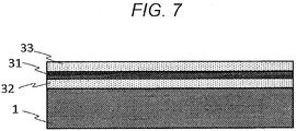
- FIG. 7 is a schematic diagram of an outer layer structure of a fuel cladding tube according to the present embodiment in which both a middle layer 32 and a protection layer 33 are provided.
- the middle layer 32 is formed on a side of an outer surface of a base material 1 formed of a SiC tube, and a rare earth silicate layer 31 is formed on a side of an outer surface of the middle layer 32.
- the protection layer 33 is formed on a side of an outer surface of the rare earth silicate layer 31.
- the middle layer 32 and the protection layer 33 are high purity SiC layers and are formed by using an evaporation method.
- a tubular body according to the present invention is suitable for a nuclear fuel rod in a fuel assembly and a water rod for using a tubular body which has the same structure as a cladding tube of a fuel rod.
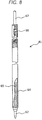
- FIG. 8 is a partial sectional diagram of a fuel rod for a boiling water reactor produced by applying the present invention.
- a nuclear fuel rod 41 is formed of a cladding tube 64 including nuclear fuel pellets 65.
- a plenum spring 66 is provided in the upper part of the cladding tube 64. Both ends of the cladding tube 64 are sealed with end plugs 67.
- the cladding tube 64 has a small diameter part 68.
- the cladding tube 64 is a fuel cladding tube according to any one of the first to sixth embodiments.
- FIGS. 9 and 10 are partial sectional diagrams of the water rod produced by applying the present invention.
- a water rod 42 illustrated in FIG. 9 has a hollow cylindrical shape having a uniform diameter, and both ends of the water rod 42 are sealed with end plugs 70.
- the water rod 42 illustrated in FIG. 10 has a large diameter part 69 in a center part and has the small diameter parts 68 on both ends. Also, both ends are sealed with the end plugs 70.
- the water rods illustrated in FIGS. 9 and 9 are formed of a tubular body having a structure same as that of the fuel cladding tube according to any one of the first to sixth embodiments.
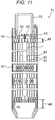
- FIG. 11 is a schematic diagram of a fuel assembly including the tubular body according to the present invention.
- a fuel assembly 71 has the nuclear fuel rods 41 (nuclear fuel cladding tube) and the water rod 42 formed in a bundle by a upper tie plate 45, a lower tie plate 46, a spacer 47, and the like and covered with a channel box 44.
- a nuclear fuel rod through-hole 50 and a water rod fixing screw 53 are provided in the upper tie plate 45. Also, a handle 51 is attached to the upper part of the upper tie plate 45. A nuclear fuel rod margin 49 is provided between the upper tie plate 45 and the nuclear fuel rod 41. A channel box fitting margin 48 is provided below the channel box 44.
- the nuclear fuel rod for using the fuel cladding tube configured of the tubular body according to the present invention and the fuel assembly including the water rod for using the tubular body having the same structure as that of the fuel cladding tube can contain the radioactive nuclide in the fuel rod.
- an amount of hydrogen generated by the reaction between the SiC of the base material and the high temperature steam can be largely reduced.
- the tubular body according to the present invention can be applied to not only the fuel cladding tube and the water rod of the fuel assembly in the boiling water reactor illustrated in FIGS. 8 to 11 but also a cladding tube of a fuel rod of a pressurized water reactor illustrated in FIGS. 12 to 14 .
- FIG. 12 A configuration diagram of the fuel assembly according to the present embodiment is illustrated in FIG. 12 , and a cross sectional diagram of the fuel assembly is illustrated in FIG. 13 .
- a fuel assembly 81 mainly includes 264 fuel rods 82, 24 control rod guide thimbles 83, an incore instrumentation guide thimble 84, nine support grids 85 as support structures, a upper nozzle 86, and a lower nozzle 87.
- the fuel rods 82 are arrayed in a square having 17 rows and 17 columns.
- Gaps are provided between both ends of the fuel rod 82 and the nozzles, and thermal expansion and growth of the fuel rod 82 can be allowed.
- Major functions of the upper nozzle 86 and the lower nozzle 87 are to form a framework of the assembly 81 and to position the assembly 81 in a core part and to ensure a flow path of cooling water.
- FIG. 14 A partial sectional diagram of the structure of the fuel rod according to the present embodiment is illustrated in FIG. 14 .
- the fuel rod 82 has a structure in which pellets are arranged in a single line and put in a fuel cladding tube 91 filled with helium gas and both ends of the fuel cladding tube 91 are respectively sealed with end plugs 92.
- Empty parts plenum 93 to accumulate fission product gas discharged from the pellets are provided in the fuel rod 82.
- a volume of the plenum 93 is large enough so as not to have excessive inner pressure caused by discharged fission product gas and other gas.
- coil springs 94 plenum spring to prevent movements of pellets 95 at the time of transfer or operation are provided.
- the fuel cladding tube 91 is configured of the fuel cladding tube according to any one of the first to sixth embodiments.
- radioactive nuclide in the fuel rod can be contained by using the nuclear fuel rod for using the fuel cladding tube configured of the tubular body according to the present invention. Also, in case of an accident, an amount of hydrogen generated by a reaction between SiC of a base material and high temperature steam can be largely reduced.
- the present invention is not limited to the embodiments and can be variously changed and modified.
- the tubular body according to the present invention can be applied to components of plant equipment, power generation equipment, and an engine of a mobile body.
- a medium to be a corrosive environment including high temperature steam and the component can be used as a heat exchange pipe and a heating element to which heat is transferred via a material or medium in the pipe and a pipe wall.
Landscapes
- Chemical & Material Sciences (AREA)
- Engineering & Computer Science (AREA)
- Ceramic Engineering (AREA)
- Materials Engineering (AREA)
- Structural Engineering (AREA)
- Organic Chemistry (AREA)
- Manufacturing & Machinery (AREA)
- Physics & Mathematics (AREA)
- Chemical Kinetics & Catalysis (AREA)
- Metallurgy (AREA)
- Plasma & Fusion (AREA)
- General Engineering & Computer Science (AREA)
- High Energy & Nuclear Physics (AREA)
- Laminated Bodies (AREA)
- Rigid Pipes And Flexible Pipes (AREA)
- Physical Vapour Deposition (AREA)
Applications Claiming Priority (1)
| Application Number | Priority Date | Filing Date | Title |
|---|---|---|---|
| PCT/JP2013/066179 WO2014199459A1 (fr) | 2013-06-12 | 2013-06-12 | Corps tubulaire et procédé de fabrication de corps tubulaire |
Publications (3)
| Publication Number | Publication Date |
|---|---|
| EP3010024A1 true EP3010024A1 (fr) | 2016-04-20 |
| EP3010024A4 EP3010024A4 (fr) | 2017-01-25 |
| EP3010024B1 EP3010024B1 (fr) | 2017-11-08 |
Family
ID=52021793
Family Applications (1)
| Application Number | Title | Priority Date | Filing Date |
|---|---|---|---|
| EP13886864.1A Not-in-force EP3010024B1 (fr) | 2013-06-12 | 2013-06-12 | Corps tubulaire et procédé de fabrication de corps tubulaire |
Country Status (3)
| Country | Link |
|---|---|
| EP (1) | EP3010024B1 (fr) |
| JP (1) | JP6082810B2 (fr) |
| WO (1) | WO2014199459A1 (fr) |
Cited By (4)
| Publication number | Priority date | Publication date | Assignee | Title |
|---|---|---|---|---|
| CN105858673A (zh) * | 2016-05-27 | 2016-08-17 | 陕西科技大学 | 一种采用两步法合成Yb2Si2O7粉体的方法 |
| CN106064820A (zh) * | 2016-05-27 | 2016-11-02 | 陕西科技大学 | 一种棒状Yb2Si2O7粉体的制备方法 |
| KR20190051969A (ko) * | 2016-08-08 | 2019-05-15 | 제너럴 아토믹스 | 엔지니어링된 sic-sic 복합체 및 모놀리식 sic 층상 구조체 |
| JP2022508196A (ja) * | 2018-11-20 | 2022-01-19 | ウェスティングハウス エレクトリック カンパニー エルエルシー | 軽水炉運転中のSiC被覆管を沈静化させるための被膜及び表面改質 |
Families Citing this family (16)
| Publication number | Priority date | Publication date | Assignee | Title |
|---|---|---|---|---|
| JP6632931B2 (ja) * | 2016-04-28 | 2020-01-22 | 日立Geニュークリア・エナジー株式会社 | 構造部材およびその製造方法、燃料棒、燃料チャンネルボックス、ウォーターロッド、燃料集合体 |
| JP6797605B2 (ja) * | 2016-08-24 | 2020-12-09 | 株式会社東芝 | 長繊維強化炭化ケイ素部材、および、その製造方法 |
| WO2018060644A1 (fr) * | 2016-09-28 | 2018-04-05 | Commissariat A L'energie Atomique Et Aux Energies Alternatives | Composant nucléaire composite, procédé de fabrication par dli-mocvd et utilisations contre l'oxydation/hydruration |
| CN107640976B (zh) * | 2016-10-09 | 2019-12-20 | 中国人民解放军国防科学技术大学 | 三维碳化硅纤维预制件增强硅酸钇复合材料及其制备方法 |
| US11780780B2 (en) | 2017-03-20 | 2023-10-10 | United States Of America As Represented By The Secretary Of The Air Force | Oxidation-resistant fiber coatings and related methods |
| JP6917770B2 (ja) * | 2017-05-15 | 2021-08-11 | 株式会社東芝 | 長繊維強化炭化ケイ素部材、その製造方法、および、原子炉構造部材 |
| JP6850209B2 (ja) * | 2017-06-23 | 2021-03-31 | 日立Geニュークリア・エナジー株式会社 | 接合部材、それを用いた接合構造体及び接合部材の製造方法 |
| CN108405646B (zh) * | 2018-03-19 | 2019-10-15 | 福建奋安铝业有限公司 | 一种铝型材挤压模具及其加工工艺 |
| RU2021127618A (ru) * | 2018-06-21 | 2021-11-16 | БВКсТ НЬЮКЛИАР ЭНЕРДЖИ, ИНК. | Универсальный инвертированный реактор и способ для проектирования и изготовления универсального инвертированного реактора |
| JP6868601B2 (ja) * | 2018-11-01 | 2021-05-12 | 株式会社フェローテックマテリアルテクノロジーズ | SiC繊維を内包する管状体およびその製造方法 |
| CN109767849A (zh) * | 2019-03-28 | 2019-05-17 | 崇义恒毅陶瓷复合材料有限公司 | 包壳管及其制备方法 |
| KR102168888B1 (ko) * | 2019-04-26 | 2020-10-22 | 인천대학교 산학협력단 | 실리케이트를 이용한 사고 저항성 핵연료 피복관의 코팅방법 및 이를 이용한 핵연료 피복관 |
| CN110330353B (zh) * | 2019-08-15 | 2020-03-13 | 中南大学 | 一种SiCf/SiC复合材料火焰筒及其自动化制备方法 |
| JP7173372B2 (ja) * | 2019-10-17 | 2022-11-16 | 株式会社Ihi | セラミックス基複合材料及びその製造方法 |
| KR102356029B1 (ko) * | 2021-05-26 | 2022-02-08 | 주식회사 그린리소스 | 실리케이트 코팅재의 제조 방법 |
| CN114907127B (zh) * | 2022-05-09 | 2023-04-28 | 厦门大学 | 一种基体改性的SiC/SiC复合材料及其制备方法 |
Family Cites Families (7)
| Publication number | Priority date | Publication date | Assignee | Title |
|---|---|---|---|---|
| JPH0424320Y2 (fr) * | 1988-05-09 | 1992-06-08 | ||
| US5699396A (en) * | 1994-11-21 | 1997-12-16 | General Electric Company | Corrosion resistant zirconium alloy for extended-life fuel cladding |
| US6243433B1 (en) * | 1999-05-14 | 2001-06-05 | General Electic Co. | Cladding for use in nuclear reactors having improved resistance to stress corrosion cracking and corrosion |
| US20060039524A1 (en) | 2004-06-07 | 2006-02-23 | Herbert Feinroth | Multi-layered ceramic tube for fuel containment barrier and other applications in nuclear and fossil power plants |
| US20060014029A1 (en) * | 2004-07-15 | 2006-01-19 | General Electric Company | Article including environmental barrier coating system, and method for making |
| JP4690709B2 (ja) * | 2004-11-26 | 2011-06-01 | 三菱重工業株式会社 | 耐熱材料およびその製造方法 |
| JP2009210266A (ja) * | 2008-02-29 | 2009-09-17 | Ibiden Co Ltd | 管状体 |
-
2013
- 2013-06-12 WO PCT/JP2013/066179 patent/WO2014199459A1/fr active Application Filing
- 2013-06-12 JP JP2015522323A patent/JP6082810B2/ja not_active Expired - Fee Related
- 2013-06-12 EP EP13886864.1A patent/EP3010024B1/fr not_active Not-in-force
Cited By (6)
| Publication number | Priority date | Publication date | Assignee | Title |
|---|---|---|---|---|
| CN105858673A (zh) * | 2016-05-27 | 2016-08-17 | 陕西科技大学 | 一种采用两步法合成Yb2Si2O7粉体的方法 |
| CN106064820A (zh) * | 2016-05-27 | 2016-11-02 | 陕西科技大学 | 一种棒状Yb2Si2O7粉体的制备方法 |
| CN105858673B (zh) * | 2016-05-27 | 2018-02-16 | 陕西科技大学 | 一种采用两步法合成Yb2Si2O7粉体的方法 |
| CN106064820B (zh) * | 2016-05-27 | 2018-06-26 | 陕西科技大学 | 一种棒状Yb2Si2O7粉体的制备方法 |
| KR20190051969A (ko) * | 2016-08-08 | 2019-05-15 | 제너럴 아토믹스 | 엔지니어링된 sic-sic 복합체 및 모놀리식 sic 층상 구조체 |
| JP2022508196A (ja) * | 2018-11-20 | 2022-01-19 | ウェスティングハウス エレクトリック カンパニー エルエルシー | 軽水炉運転中のSiC被覆管を沈静化させるための被膜及び表面改質 |
Also Published As
| Publication number | Publication date |
|---|---|
| JPWO2014199459A1 (ja) | 2017-02-23 |
| WO2014199459A1 (fr) | 2014-12-18 |
| EP3010024A4 (fr) | 2017-01-25 |
| EP3010024B1 (fr) | 2017-11-08 |
| JP6082810B2 (ja) | 2017-02-15 |
Similar Documents
| Publication | Publication Date | Title |
|---|---|---|
| EP3010024B1 (fr) | Corps tubulaire et procédé de fabrication de corps tubulaire | |
| EP3117440B1 (fr) | Bouchon d'extrémité de barre de combustible à double étanchéité pour gainage contenant de la céramique | |
| JP4763699B2 (ja) | 原子力発電所における燃料格納容器障壁等に使用される多層セラミックチューブ | |
| EP3383644B1 (fr) | Système de gainage de combustible composite multicouche avec herméticité vis-à-vis de la température et tolérance aux accidents élevées | |
| EP3117439B1 (fr) | Gainage pour combustible nucléaire en alliage de zirconium renforcé de céramique avec une couche résistant à l'oxydation intermédiaire | |
| EP3226247B1 (fr) | Barres de combustible de réacteur nucléaire groupées dans un ensemble combustible et ledit ensemble combustible | |
| CN108140434B (zh) | 锆合金包壳上的腐蚀和磨损抵抗性涂层 | |
| US11862351B2 (en) | Zirconium-coated silicon carbide fuel cladding for accident tolerant fuel application | |
| JP6850209B2 (ja) | 接合部材、それを用いた接合構造体及び接合部材の製造方法 | |
| JP6632931B2 (ja) | 構造部材およびその製造方法、燃料棒、燃料チャンネルボックス、ウォーターロッド、燃料集合体 | |
| JP7350254B2 (ja) | 端栓が接合された燃料棒 |
Legal Events
| Date | Code | Title | Description |
|---|---|---|---|
| PUAI | Public reference made under article 153(3) epc to a published international application that has entered the european phase |
Free format text: ORIGINAL CODE: 0009012 |
|
| 17P | Request for examination filed |
Effective date: 20160112 |
|
| AK | Designated contracting states |
Kind code of ref document: A1 Designated state(s): AL AT BE BG CH CY CZ DE DK EE ES FI FR GB GR HR HU IE IS IT LI LT LU LV MC MK MT NL NO PL PT RO RS SE SI SK SM TR |
|
| AX | Request for extension of the european patent |
Extension state: BA ME |
|
| DAX | Request for extension of the european patent (deleted) | ||
| RIN1 | Information on inventor provided before grant (corrected) |
Inventor name: AOYAMA, MOTOO Inventor name: KITO, KAZUAKI Inventor name: NAKANE, MOTOKI Inventor name: SEKIHARA, MASARU Inventor name: HINO, TETSUSHI Inventor name: NAKANO, HIROSHI Inventor name: ISHIBASHI, RYOU Inventor name: TAKAHASHI, KATSUHITO Inventor name: KAMOSHIDA, MAMORU Inventor name: HASHIMOTO, TSUNEYUKI Inventor name: KAWAMURA, TOSHINORI Inventor name: CHAKI, MASAO |
|
| A4 | Supplementary search report drawn up and despatched |
Effective date: 20161223 |
|
| RIC1 | Information provided on ipc code assigned before grant |
Ipc: G21C 3/06 20060101AFI20161219BHEP Ipc: C04B 35/80 20060101ALI20161219BHEP Ipc: G21C 3/326 20060101ALI20161219BHEP Ipc: C04B 41/89 20060101ALI20161219BHEP |
|
| GRAP | Despatch of communication of intention to grant a patent |
Free format text: ORIGINAL CODE: EPIDOSNIGR1 |
|
| INTG | Intention to grant announced |
Effective date: 20170517 |
|
| GRAS | Grant fee paid |
Free format text: ORIGINAL CODE: EPIDOSNIGR3 |
|
| GRAA | (expected) grant |
Free format text: ORIGINAL CODE: 0009210 |
|
| AK | Designated contracting states |
Kind code of ref document: B1 Designated state(s): AL AT BE BG CH CY CZ DE DK EE ES FI FR GB GR HR HU IE IS IT LI LT LU LV MC MK MT NL NO PL PT RO RS SE SI SK SM TR |
|
| REG | Reference to a national code |
Ref country code: GB Ref legal event code: FG4D |
|
| REG | Reference to a national code |
Ref country code: CH Ref legal event code: EP Ref country code: AT Ref legal event code: REF Ref document number: 944877 Country of ref document: AT Kind code of ref document: T Effective date: 20171115 |
|
| REG | Reference to a national code |
Ref country code: IE Ref legal event code: FG4D |
|
| REG | Reference to a national code |
Ref country code: DE Ref legal event code: R096 Ref document number: 602013029326 Country of ref document: DE |
|
| REG | Reference to a national code |
Ref country code: NL Ref legal event code: MP Effective date: 20171108 |
|
| REG | Reference to a national code |
Ref country code: LT Ref legal event code: MG4D |
|
| REG | Reference to a national code |
Ref country code: AT Ref legal event code: MK05 Ref document number: 944877 Country of ref document: AT Kind code of ref document: T Effective date: 20171108 |
|
| PG25 | Lapsed in a contracting state [announced via postgrant information from national office to epo] |
Ref country code: FI Free format text: LAPSE BECAUSE OF FAILURE TO SUBMIT A TRANSLATION OF THE DESCRIPTION OR TO PAY THE FEE WITHIN THE PRESCRIBED TIME-LIMIT Effective date: 20171108 Ref country code: NL Free format text: LAPSE BECAUSE OF FAILURE TO SUBMIT A TRANSLATION OF THE DESCRIPTION OR TO PAY THE FEE WITHIN THE PRESCRIBED TIME-LIMIT Effective date: 20171108 Ref country code: ES Free format text: LAPSE BECAUSE OF FAILURE TO SUBMIT A TRANSLATION OF THE DESCRIPTION OR TO PAY THE FEE WITHIN THE PRESCRIBED TIME-LIMIT Effective date: 20171108 Ref country code: SE Free format text: LAPSE BECAUSE OF FAILURE TO SUBMIT A TRANSLATION OF THE DESCRIPTION OR TO PAY THE FEE WITHIN THE PRESCRIBED TIME-LIMIT Effective date: 20171108 Ref country code: NO Free format text: LAPSE BECAUSE OF FAILURE TO SUBMIT A TRANSLATION OF THE DESCRIPTION OR TO PAY THE FEE WITHIN THE PRESCRIBED TIME-LIMIT Effective date: 20180208 Ref country code: LT Free format text: LAPSE BECAUSE OF FAILURE TO SUBMIT A TRANSLATION OF THE DESCRIPTION OR TO PAY THE FEE WITHIN THE PRESCRIBED TIME-LIMIT Effective date: 20171108 |
|
| PG25 | Lapsed in a contracting state [announced via postgrant information from national office to epo] |
Ref country code: HR Free format text: LAPSE BECAUSE OF FAILURE TO SUBMIT A TRANSLATION OF THE DESCRIPTION OR TO PAY THE FEE WITHIN THE PRESCRIBED TIME-LIMIT Effective date: 20171108 Ref country code: IS Free format text: LAPSE BECAUSE OF FAILURE TO SUBMIT A TRANSLATION OF THE DESCRIPTION OR TO PAY THE FEE WITHIN THE PRESCRIBED TIME-LIMIT Effective date: 20180308 Ref country code: AT Free format text: LAPSE BECAUSE OF FAILURE TO SUBMIT A TRANSLATION OF THE DESCRIPTION OR TO PAY THE FEE WITHIN THE PRESCRIBED TIME-LIMIT Effective date: 20171108 Ref country code: BG Free format text: LAPSE BECAUSE OF FAILURE TO SUBMIT A TRANSLATION OF THE DESCRIPTION OR TO PAY THE FEE WITHIN THE PRESCRIBED TIME-LIMIT Effective date: 20180208 Ref country code: GR Free format text: LAPSE BECAUSE OF FAILURE TO SUBMIT A TRANSLATION OF THE DESCRIPTION OR TO PAY THE FEE WITHIN THE PRESCRIBED TIME-LIMIT Effective date: 20180209 Ref country code: RS Free format text: LAPSE BECAUSE OF FAILURE TO SUBMIT A TRANSLATION OF THE DESCRIPTION OR TO PAY THE FEE WITHIN THE PRESCRIBED TIME-LIMIT Effective date: 20171108 Ref country code: LV Free format text: LAPSE BECAUSE OF FAILURE TO SUBMIT A TRANSLATION OF THE DESCRIPTION OR TO PAY THE FEE WITHIN THE PRESCRIBED TIME-LIMIT Effective date: 20171108 |
|
| REG | Reference to a national code |
Ref country code: FR Ref legal event code: PLFP Year of fee payment: 6 |
|
| PG25 | Lapsed in a contracting state [announced via postgrant information from national office to epo] |
Ref country code: SK Free format text: LAPSE BECAUSE OF FAILURE TO SUBMIT A TRANSLATION OF THE DESCRIPTION OR TO PAY THE FEE WITHIN THE PRESCRIBED TIME-LIMIT Effective date: 20171108 Ref country code: CY Free format text: LAPSE BECAUSE OF FAILURE TO SUBMIT A TRANSLATION OF THE DESCRIPTION OR TO PAY THE FEE WITHIN THE PRESCRIBED TIME-LIMIT Effective date: 20171108 Ref country code: EE Free format text: LAPSE BECAUSE OF FAILURE TO SUBMIT A TRANSLATION OF THE DESCRIPTION OR TO PAY THE FEE WITHIN THE PRESCRIBED TIME-LIMIT Effective date: 20171108 Ref country code: CZ Free format text: LAPSE BECAUSE OF FAILURE TO SUBMIT A TRANSLATION OF THE DESCRIPTION OR TO PAY THE FEE WITHIN THE PRESCRIBED TIME-LIMIT Effective date: 20171108 Ref country code: DK Free format text: LAPSE BECAUSE OF FAILURE TO SUBMIT A TRANSLATION OF THE DESCRIPTION OR TO PAY THE FEE WITHIN THE PRESCRIBED TIME-LIMIT Effective date: 20171108 |
|
| REG | Reference to a national code |
Ref country code: DE Ref legal event code: R097 Ref document number: 602013029326 Country of ref document: DE |
|
| PG25 | Lapsed in a contracting state [announced via postgrant information from national office to epo] |
Ref country code: SM Free format text: LAPSE BECAUSE OF FAILURE TO SUBMIT A TRANSLATION OF THE DESCRIPTION OR TO PAY THE FEE WITHIN THE PRESCRIBED TIME-LIMIT Effective date: 20171108 Ref country code: PL Free format text: LAPSE BECAUSE OF FAILURE TO SUBMIT A TRANSLATION OF THE DESCRIPTION OR TO PAY THE FEE WITHIN THE PRESCRIBED TIME-LIMIT Effective date: 20171108 Ref country code: RO Free format text: LAPSE BECAUSE OF FAILURE TO SUBMIT A TRANSLATION OF THE DESCRIPTION OR TO PAY THE FEE WITHIN THE PRESCRIBED TIME-LIMIT Effective date: 20171108 Ref country code: IT Free format text: LAPSE BECAUSE OF FAILURE TO SUBMIT A TRANSLATION OF THE DESCRIPTION OR TO PAY THE FEE WITHIN THE PRESCRIBED TIME-LIMIT Effective date: 20171108 |
|
| PLBE | No opposition filed within time limit |
Free format text: ORIGINAL CODE: 0009261 |
|
| STAA | Information on the status of an ep patent application or granted ep patent |
Free format text: STATUS: NO OPPOSITION FILED WITHIN TIME LIMIT |
|
| 26N | No opposition filed |
Effective date: 20180809 |
|
| PG25 | Lapsed in a contracting state [announced via postgrant information from national office to epo] |
Ref country code: SI Free format text: LAPSE BECAUSE OF FAILURE TO SUBMIT A TRANSLATION OF THE DESCRIPTION OR TO PAY THE FEE WITHIN THE PRESCRIBED TIME-LIMIT Effective date: 20171108 |
|
| REG | Reference to a national code |
Ref country code: DE Ref legal event code: R119 Ref document number: 602013029326 Country of ref document: DE |
|
| REG | Reference to a national code |
Ref country code: CH Ref legal event code: PL |
|
| REG | Reference to a national code |
Ref country code: BE Ref legal event code: MM Effective date: 20180630 |
|
| REG | Reference to a national code |
Ref country code: IE Ref legal event code: MM4A |
|
| PG25 | Lapsed in a contracting state [announced via postgrant information from national office to epo] |
Ref country code: LU Free format text: LAPSE BECAUSE OF NON-PAYMENT OF DUE FEES Effective date: 20180612 Ref country code: MC Free format text: LAPSE BECAUSE OF FAILURE TO SUBMIT A TRANSLATION OF THE DESCRIPTION OR TO PAY THE FEE WITHIN THE PRESCRIBED TIME-LIMIT Effective date: 20171108 |
|
| PG25 | Lapsed in a contracting state [announced via postgrant information from national office to epo] |
Ref country code: CH Free format text: LAPSE BECAUSE OF NON-PAYMENT OF DUE FEES Effective date: 20180630 Ref country code: LI Free format text: LAPSE BECAUSE OF NON-PAYMENT OF DUE FEES Effective date: 20180630 Ref country code: IE Free format text: LAPSE BECAUSE OF NON-PAYMENT OF DUE FEES Effective date: 20180612 Ref country code: DE Free format text: LAPSE BECAUSE OF NON-PAYMENT OF DUE FEES Effective date: 20190101 |
|
| PG25 | Lapsed in a contracting state [announced via postgrant information from national office to epo] |
Ref country code: BE Free format text: LAPSE BECAUSE OF NON-PAYMENT OF DUE FEES Effective date: 20180630 |
|
| PG25 | Lapsed in a contracting state [announced via postgrant information from national office to epo] |
Ref country code: MT Free format text: LAPSE BECAUSE OF NON-PAYMENT OF DUE FEES Effective date: 20180612 |
|
| PG25 | Lapsed in a contracting state [announced via postgrant information from national office to epo] |
Ref country code: TR Free format text: LAPSE BECAUSE OF FAILURE TO SUBMIT A TRANSLATION OF THE DESCRIPTION OR TO PAY THE FEE WITHIN THE PRESCRIBED TIME-LIMIT Effective date: 20171108 |
|
| PG25 | Lapsed in a contracting state [announced via postgrant information from national office to epo] |
Ref country code: PT Free format text: LAPSE BECAUSE OF FAILURE TO SUBMIT A TRANSLATION OF THE DESCRIPTION OR TO PAY THE FEE WITHIN THE PRESCRIBED TIME-LIMIT Effective date: 20171108 |
|
| PG25 | Lapsed in a contracting state [announced via postgrant information from national office to epo] |
Ref country code: HU Free format text: LAPSE BECAUSE OF FAILURE TO SUBMIT A TRANSLATION OF THE DESCRIPTION OR TO PAY THE FEE WITHIN THE PRESCRIBED TIME-LIMIT; INVALID AB INITIO Effective date: 20130612 Ref country code: MK Free format text: LAPSE BECAUSE OF NON-PAYMENT OF DUE FEES Effective date: 20171108 |
|
| PG25 | Lapsed in a contracting state [announced via postgrant information from national office to epo] |
Ref country code: AL Free format text: LAPSE BECAUSE OF FAILURE TO SUBMIT A TRANSLATION OF THE DESCRIPTION OR TO PAY THE FEE WITHIN THE PRESCRIBED TIME-LIMIT Effective date: 20171108 |
|
| PGFP | Annual fee paid to national office [announced via postgrant information from national office to epo] |
Ref country code: FR Payment date: 20210513 Year of fee payment: 9 |
|
| PGFP | Annual fee paid to national office [announced via postgrant information from national office to epo] |
Ref country code: GB Payment date: 20210519 Year of fee payment: 9 |
|
| GBPC | Gb: european patent ceased through non-payment of renewal fee |
Effective date: 20220612 |
|
| PG25 | Lapsed in a contracting state [announced via postgrant information from national office to epo] |
Ref country code: FR Free format text: LAPSE BECAUSE OF NON-PAYMENT OF DUE FEES Effective date: 20220630 |
|
| PG25 | Lapsed in a contracting state [announced via postgrant information from national office to epo] |
Ref country code: GB Free format text: LAPSE BECAUSE OF NON-PAYMENT OF DUE FEES Effective date: 20220612 |