EP3002128A2 - Procede et dispositif d'impression d'une surface courbee d'un objet a l'aide d'une tete d'impression a jet d'encre - Google Patents
Procede et dispositif d'impression d'une surface courbee d'un objet a l'aide d'une tete d'impression a jet d'encre Download PDFInfo
- Publication number
- EP3002128A2 EP3002128A2 EP15178766.0A EP15178766A EP3002128A2 EP 3002128 A2 EP3002128 A2 EP 3002128A2 EP 15178766 A EP15178766 A EP 15178766A EP 3002128 A2 EP3002128 A2 EP 3002128A2
- Authority
- EP
- European Patent Office
- Prior art keywords
- track
- web
- printing
- path
- prints
- Prior art date
- Legal status (The legal status is an assumption and is not a legal conclusion. Google has not performed a legal analysis and makes no representation as to the accuracy of the status listed.)
- Granted
Links
- 238000000034 method Methods 0.000 title claims abstract description 42
- 238000007639 printing Methods 0.000 title claims abstract description 28
- 230000033001 locomotion Effects 0.000 claims abstract description 15
- 238000011161 development Methods 0.000 description 9
- 230000018109 developmental process Effects 0.000 description 9
- 239000003086 colorant Substances 0.000 description 5
- 239000000758 substrate Substances 0.000 description 3
- 206010013786 Dry skin Diseases 0.000 description 2
- 230000003287 optical effect Effects 0.000 description 2
- 230000003252 repetitive effect Effects 0.000 description 2
- 230000001133 acceleration Effects 0.000 description 1
- 230000006978 adaptation Effects 0.000 description 1
- WYTGDNHDOZPMIW-RCBQFDQVSA-N alstonine Natural products C1=CC2=C3C=CC=CC3=NC2=C2N1C[C@H]1[C@H](C)OC=C(C(=O)OC)[C@H]1C2 WYTGDNHDOZPMIW-RCBQFDQVSA-N 0.000 description 1
- 230000000295 complement effect Effects 0.000 description 1
- 230000001419 dependent effect Effects 0.000 description 1
- 238000001035 drying Methods 0.000 description 1
- 230000000694 effects Effects 0.000 description 1
- 238000007641 inkjet printing Methods 0.000 description 1
- 238000000926 separation method Methods 0.000 description 1
- 239000007787 solid Substances 0.000 description 1
- 238000004804 winding Methods 0.000 description 1
Images

Classifications
-
- B—PERFORMING OPERATIONS; TRANSPORTING
- B41—PRINTING; LINING MACHINES; TYPEWRITERS; STAMPS
- B41J—TYPEWRITERS; SELECTIVE PRINTING MECHANISMS, i.e. MECHANISMS PRINTING OTHERWISE THAN FROM A FORME; CORRECTION OF TYPOGRAPHICAL ERRORS
- B41J25/00—Actions or mechanisms not otherwise provided for
- B41J25/001—Mechanisms for bodily moving print heads or carriages parallel to the paper surface
- B41J25/003—Mechanisms for bodily moving print heads or carriages parallel to the paper surface for changing the angle between a print element array axis and the printing line, e.g. for dot density changes
-
- B—PERFORMING OPERATIONS; TRANSPORTING
- B41—PRINTING; LINING MACHINES; TYPEWRITERS; STAMPS
- B41J—TYPEWRITERS; SELECTIVE PRINTING MECHANISMS, i.e. MECHANISMS PRINTING OTHERWISE THAN FROM A FORME; CORRECTION OF TYPOGRAPHICAL ERRORS
- B41J25/00—Actions or mechanisms not otherwise provided for
- B41J25/001—Mechanisms for bodily moving print heads or carriages parallel to the paper surface
- B41J25/005—Mechanisms for bodily moving print heads or carriages parallel to the paper surface for serial printing movements superimposed to character- or line-spacing movements
-
- B—PERFORMING OPERATIONS; TRANSPORTING
- B41—PRINTING; LINING MACHINES; TYPEWRITERS; STAMPS
- B41J—TYPEWRITERS; SELECTIVE PRINTING MECHANISMS, i.e. MECHANISMS PRINTING OTHERWISE THAN FROM A FORME; CORRECTION OF TYPOGRAPHICAL ERRORS
- B41J3/00—Typewriters or selective printing or marking mechanisms characterised by the purpose for which they are constructed
- B41J3/407—Typewriters or selective printing or marking mechanisms characterised by the purpose for which they are constructed for marking on special material
- B41J3/4073—Printing on three-dimensional objects not being in sheet or web form, e.g. spherical or cubic objects
Definitions
- the present invention relates to a method comprising the features of the preamble of claim 1. Furthermore, the present invention relates to a device having the features of the preamble of claim 9.
- the invention is in the technical field of ink jet printing, in particular the printing of non-planar, but curved substrates.
- "Curved” means that the surface has convex and / or concave portions, etc., such as e.g. Body parts of vehicles.
- a plurality of short tracks also create a plurality of terminals of the tracks to each other. This can also increase the likelihood of noticeable disturbances.
- An inventive method for printing at least a portion of a flat or preferably curved surface of an object wherein an ink jet head is moved by a relative movement between the ink jet head and object along a first path, thereby printing a first track, and is moved along a second path, and a second track prints, characterized in that a first track edge of the first track and a second track edge of the second track meet at a point and at an angle between about 1 ° and about 179 °, preferably between about 5 ° and about 175 ° include.
- the angle between the track edges is not 0 ° and also not 180 °, ie the two printed tracks are not parallel to each other.
- the angle is not 90 ° or not in the range between about 85 ° and 95 °, ie the two printed tracks are not perpendicular to each other.
- b distance between two adjacent nozzles of a print head
- 1 distance between two consecutive pressure points in the direction of movement of the print head
- n, m natural numbers. This ensures that the respective last pressure point of a pressure point row of a second track has the same distance from the pressure points of the first track adjacent to the second track, so that a homogeneous transitional area is created between the two tracks.
- the image to be printed and composed of the tracks is screened, it may be advantageous to choose the screen angles within two tracks so that they are matched to the angle between the track edges of the two tracks and the occurrence of noticeable connections of the tracks to each other reduce.
- the tracks may be approximately straight along the curved surface. However, they can also have curves.
- the width of the tracks may be substantially constant. However, the width may also change, e.g. can decrease the width by turning the print head or by turning off nozzles on the edge of the head.
- each pixel is printed only once, even with repeated passing over the print head.
- Pressure points in the respective area of the connection of two tracks are preferably assigned to one of the two tracks in the RIP.
- the track edges can preferably be printed expiring and mesh with adjacent track edges (so-called stitching).
- the inventive method described can advantageously lead to a lack of mechatronic precision of a robot-controlled ink jet head not or only to a lesser extent perceptible because disturbing lines are avoided, i. longer parallel pressure gaps with reduced optical density or print overlaps with increased optical density. Such lines perceive the human eye much more sensitive than mutually angled deviations of the pressure points of a given ideal grid.
- a robot which moves the print head can vary the printing webs, at least in the image plane, because the webs no longer necessarily have to be parallel. This reduces the number of singularities and increases the space in which the robot can print. In other words, by the non-parallel web guide larger objects can be printed with the same robot, as in the case of parallel web guide.
- a preferred embodiment of the method according to the invention may be characterized in that the angle is between about 20 ° and about 70 ° or between about 110 ° and about 160 °, preferably about 45 ° or about 135 °.
- a preferred development of the method according to the invention can be distinguished by the fact that the first web and the second web overlap in an overlapping region.
- a preferred development of the method according to the invention can be distinguished by the fact that the inkjet head prints in at least part of the overlap region only on the first web or on the second web, in particular that the inkjet head prints on the first web in the entire overlap region and not on the second web prints.
- a preferred development of the method according to the invention can be distinguished by the fact that the second path crosses the first path in the overlapping region.
- the image area to be printed can be generated when printing a track.
- the image area can be created when printing two or more tracks. With two tracks, each track can contribute about half of the pixels in the image area, with three tracks each contributing about one third.
- a preferred development of the method according to the invention can be characterized in that the second web and the first web intersect in a plurality of overlap regions.
- a preferred development of the method according to the invention may be distinguished by the fact that the section essentially consists of overlapping areas.
- a preferred development of the method according to the invention can be distinguished by the fact that the inkjet head on the first web and / or on the second web changes its orientation relative to the respective web.
- An inventive method for printing at least a portion of a flat or preferably curved surface of an object, wherein an ink jet head is moved along a first path, thereby printing a first track and moving along a second path thereby printing a second track, is characterized indicates that the inkjet head on the first web and / or on the second web changes its orientation to the respective web. This process can be referred to as a so-called "tilted pass”.
- a preferred embodiment of the method according to the invention can be characterized in that the inkjet head is rotated during its forward movement on the first path and / or on the second path about an axis, in particular about an axis perpendicular to the first track or second track axis.
- the angle of the printhead is changed to the printing direction. This changes the maximum print width of the print head, but the print dot density of the track to be printed is kept constant by compensating the print gaps of the individual print dot rows. It is also a multiple Tilted Pass possible. This creates at least one overlapping area whose print image is composed of pixels multiple tracks.
- the track to be printed - especially at the beginning or at the end of the track - can become narrower during the printing of a track and can even end in a (print) point.
- the boundary or the track edge may be curved.
- the subsequent track can also begin narrower (or in this extreme case at this point), so that the connection of two tracks can be reduced to one point. This results in tracks that (partially) have no parallel boundaries.
- the lateral connection is preferably realized by a track with a likewise curved boundary.
- a flat or flat surface can be printed with the inventive method, a flat or flat surface. It can preferably be provided that the tracks and associated tracks or track edges angle of about 120 ° to each other. Such printing may be referred to as "hexagonal printing" because of the resulting tri or hexagonal structures.
- Such flat substrates may preferably be substrates that are in an upright orientation, eg billboards or other billboards, flat sections of building facades or room walls, flat sections of sidewalls of vehicles (trucks, trailers, containers, trains, wagons), traffic or transportation vehicles signs.
- These data serve as information for a second path planning, the second path planning being different from the first path planning, i. has other trajectories.
- the actual printing takes place after this second path planning as a mosaic.
- This method should z. B. reduce moiré-like effects.
- (Edge) pressure points, which lie only proportionally on a web of the second path planning, are printed in a correspondingly proportionate size or as a gray value.
- the traces of the second mosaic can optionally be created with the printhead tilted. The pressure point rows of these tracks are then closer together, the maximum pressure point density is correspondingly higher. As a result, the theoretical pressure points of the first mosaic can be better or more accurately reproduced.
- the total print image to be generated may be mosaically composed of the tracks, with any track shapes being printable. It is noted that the track shapes fill the printed image in the manner of repetitive or non-repetitive tiling.
- the invention is not only applicable to the printing of a color, but also in the multi-color printing, eg CMYK printing.
- each color separation can be treated separately according to the invention, or the inventive method and its developments and the corresponding path planning can be performed separately for each color.
- the track edges of two or more mutually different colors are not adjacent to each other or parallel, but according to the invention include an angle different from 0 ° and 180 °.
- a corresponding method can proceed as follows: First, a first Color printed on the object, wherein the track edges of the first color include angles between about 1 ° and about 179 ° to each other, preferably between about 5 ° and about 175 °.
- the first color is pinned, ie dried, but not completely dried, or partially cured.
- a second color is printed, with attention also being paid to angles between about 1 ° and about 179 ° to each other, preferably between about 5 ° and about 175 °.
- the track edges of the second color are aligned so that they not only to each other, but also to the track edges of the first color have said angles. Accordingly, further colors are used, always making sure that all track edges to each other have the said angular relationships. Any color except the last color, if any, will be pinned. Finally, all printed colors are completely dried or hardened together.
- An alternative mechanical solution in multi-color printing may provide that the printheads for the individual colors are arranged below said angular relationship, e.g. are mounted on a robot arm. In this case, a single path planning would be sufficient for all colors, since the heads when moving the robot to each other have different (fixed) angular relationships and print corresponding "angled" tracks.
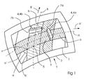
- FIG. 1 shows a schematic perspective view of an apparatus in carrying out a preferred embodiment of the method according to the invention.
- the surface is preferably curved in two spatial directions.
- a section 3 can be seen. This section should be printed.
- an ink jet head 4 is provided.
- the head is shown in two positions, once as head 4a and once as head 4b.
- the head is moved along a first path A in a first direction A '.
- the web A (and also the web B, see below) is curved according to the surface and removed from the surface in such a way that high quality printing is possible and head-to-surface collision is prevented.
- the head prints a first track a onto the surface.
- the first track A (and also the web B, see below) consists of ink drops which the head ejects by means of nozzles of a nozzle row.
- the ejection is controlled and takes into account both the movement of the head and the print image to be printed.
- the print image can be a solid or a grid. It may also be e.g. Text, picture or pattern included.
- the ink-jet head 4 is also moved along a second path B in a second direction B '.
- the movements along both paths preferably take place by means of an articulated-arm robot, linear robot or a combined robot with rotary and sliding joints.
- the movements along both tracks can be done by moving the ink jet head or by moving the object or by a combination of both movements.
- the head prints a second track b on the surface 2.
- FIG. 1 the first track edge a 'of the first track and the second track edge b' of the second track are shown. These meet at a point P and close an angle ⁇ where ⁇ is greater than 0 ° and less than 180 °, ie the two tracks are not parallel. In the example shown, the angle ⁇ is about 45 °.
- the two webs A and B overlap in an overlap region 5.
- the two tracks intersect.
- the second web b only abuts the first web a, but is not continued on the opposite side of the first web.
- the inkjet head 4 preferably prints only on one of the two webs.
- the head only prints on the first web in the overlapping area.
- the first track a is therefore an uninterrupted track and the second track b is an interrupted track, ie the overlap area forms a gap in the second track. But it is also possible that is printed in one part of the overlap area on the first path and in the complementary part on the second path.
- FIG. 1 also shows that there is at least one further overlap region 6 of the two webs A and B.
- the web B consists in this case of several track sections or a long, winding section which crosses the track A several times.
- FIG. 2 shows a schematic perspective view of a device in carrying out a further preferred embodiment of the method according to the invention.
- the ink jet head 4 is again shown in two positions: once as the ink jet head 4a and once as the ink jet head 4b.
- Head 4a is substantially parallel to the direction A 'of the first web A with respect to its first orientation 7 and substantially perpendicular to the direction A' with respect to its second orientation 7 '.
- the change in orientation is effected by rotating the head 4 about its axis 8 during forward movement, preferably by the robot.
- the respective orientation 7 and 7 'of the head is parallel to the nozzle row of the head.
- the head prints the first track a during the forward motion.
- a correspondingly adapted rotation of the head also takes place on an adjacent second web B, on which the second track b is printed.
- the adaptation of the rotations takes place in such a way that the two tracks a and b vary in their respective width in the forward direction and their edges adjoin one another without gaps.
- the edges show a serpentine course.
- its image data drive is to be varied in such a way that, despite the rotation and the resulting speeds and accelerations of the individual nozzles, a high-quality printing result is achieved.
Applications Claiming Priority (1)
| Application Number | Priority Date | Filing Date | Title |
|---|---|---|---|
| DE102014012395.2A DE102014012395A1 (de) | 2014-08-21 | 2014-08-21 | Verfahren und Vorrichtung zum Bedrucken einer gekrümmten Oberfläche eines Objekts mit einem Tintenstrahlkopf |
Publications (3)
| Publication Number | Publication Date |
|---|---|
| EP3002128A2 true EP3002128A2 (fr) | 2016-04-06 |
| EP3002128A3 EP3002128A3 (fr) | 2016-10-12 |
| EP3002128B1 EP3002128B1 (fr) | 2018-11-14 |
Family
ID=53835890
Family Applications (1)
| Application Number | Title | Priority Date | Filing Date |
|---|---|---|---|
| EP15178766.0A Active EP3002128B1 (fr) | 2014-08-21 | 2015-07-29 | Procede d'impression d'une surface courbee d'un objet a l'aide d'une tete d'impression a jet d'encre |
Country Status (4)
| Country | Link |
|---|---|
| US (2) | US9764573B2 (fr) |
| EP (1) | EP3002128B1 (fr) |
| CN (2) | CN105383185B (fr) |
| DE (1) | DE102014012395A1 (fr) |
Cited By (11)
| Publication number | Priority date | Publication date | Assignee | Title |
|---|---|---|---|---|
| DE102016014944A1 (de) * | 2016-12-14 | 2018-06-14 | Dürr Systems Ag | Beschichtungsverfahren und entsprechende Beschichtungseinrichtung |
| US11154892B2 (en) | 2016-12-14 | 2021-10-26 | Dürr Systems Ag | Coating device for applying coating agent in a controlled manner |
| US11167308B2 (en) | 2016-12-14 | 2021-11-09 | Dürr Systems Ag | Print head for the application of a coating agent on a component |
| US11167297B2 (en) | 2016-12-14 | 2021-11-09 | Dürr Systems Ag | Print head for the application of a coating agent |
| US11167302B2 (en) | 2016-12-14 | 2021-11-09 | Dürr Systems Ag | Coating device and associated operating method |
| US11298717B2 (en) | 2016-12-14 | 2022-04-12 | Dürr Systems Ag | Print head having a temperature-control device |
| US11338312B2 (en) | 2016-12-14 | 2022-05-24 | Dürr Systems Ag | Print head and associated operating method |
| US11440035B2 (en) | 2016-12-14 | 2022-09-13 | Dürr Systems Ag | Application device and method for applying a multicomponent coating medium |
| US11504735B2 (en) | 2016-12-14 | 2022-11-22 | Dürr Systems Ag | Coating device having first and second printheads and corresponding coating process |
| US11944990B2 (en) | 2016-12-14 | 2024-04-02 | Dürr Systems Ag | Coating device for coating components |
| US11975345B2 (en) | 2016-12-14 | 2024-05-07 | Dürr Systems Ag | Coating installation and corresponding coating method |
Families Citing this family (17)
| Publication number | Priority date | Publication date | Assignee | Title |
|---|---|---|---|---|
| DE102014012395A1 (de) * | 2014-08-21 | 2016-02-25 | Heidelberger Druckmaschinen Ag | Verfahren und Vorrichtung zum Bedrucken einer gekrümmten Oberfläche eines Objekts mit einem Tintenstrahlkopf |
| EP3423282A4 (fr) * | 2016-03-03 | 2019-10-09 | Inx International Ink Co. | Appareil et procédé d'impression sur des surfaces non cylindriques présentant une symétrie circulaire |
| DE102017114280B4 (de) * | 2017-06-26 | 2024-04-11 | Jörg R. Bauer | Verfahren zum Bedrucken einer gekrümmten Oberfläche sowie Vorrichtung zum Bedrucken dreidimensionaler Oberflächen |
| CN108511899B (zh) * | 2018-04-02 | 2020-02-14 | Oppo广东移动通信有限公司 | 印刷天线组件的制作方法、印刷天线组件及电子设备 |
| DE102018003096A1 (de) * | 2018-04-17 | 2019-10-17 | Burkhard Büstgens | Drop-on-Demand - Beschichtung von Oberflächen |
| DE102018210113B3 (de) | 2018-06-21 | 2019-07-11 | Heidelberger Druckmaschinen Ag | Tintenstrahl-Druckverfahren zur Erzeugung homogen aussehender Druckbilder auf sphärischen Körpern |
| CN110936735B (zh) | 2018-09-21 | 2021-12-14 | 海德堡印刷机械股份公司 | 距基底间隔可变的喷墨印刷头 |
| JP6783284B2 (ja) * | 2018-10-17 | 2020-11-11 | 株式会社大気社 | 自動描画システム及び自動描画システムの運転方法 |
| DE102018129651B4 (de) * | 2018-11-26 | 2023-11-23 | Dr. Ing. H.C. F. Porsche Aktiengesellschaft | Verfahren zum Bedrucken einer Oberfläche in mindestens zwei Druckphasen |
| US10525749B1 (en) | 2018-12-20 | 2020-01-07 | The Gillette Company Llc | Printing system having a print bed and a shielding panel |
| JP7218576B2 (ja) * | 2018-12-28 | 2023-02-07 | ブラザー工業株式会社 | 三次元印刷装置 |
| AT522737B1 (de) * | 2019-07-08 | 2021-07-15 | Franz Neuhofer | Verfahren zum digitalen Bedrucken einer Profilleiste |
| DE102019004784A1 (de) | 2019-07-09 | 2020-01-09 | Daimler Ag | Verfahren zum Drucken eines Bilds auf eine dreidimensionale Freiformfläche, sowie Vorrichtung, eingerichtet zum Durchführen eines solchen Verfahrens |
| CN114364464A (zh) * | 2019-08-30 | 2022-04-15 | 京瓷株式会社 | 涂装装置、涂装膜以及涂装方法 |
| JP7408676B2 (ja) * | 2019-10-28 | 2024-01-05 | 京セラ株式会社 | 塗装装置および払拭方法 |
| FR3111586B1 (fr) | 2020-06-17 | 2022-08-12 | Exel Ind | Procédé et installation d’application de produit de revêtement au moyen d’une tête d’impression |
| JP2022025272A (ja) * | 2020-07-29 | 2022-02-10 | セイコーエプソン株式会社 | 立体物印刷装置および立体物印刷方法 |
Citations (3)
| Publication number | Priority date | Publication date | Assignee | Title |
|---|---|---|---|---|
| DE102012006371A1 (de) | 2012-03-29 | 2012-07-05 | Heidelberger Druckmaschinen Aktiengesellschaft | Verfahren zum Bedrucken eines Objekts |
| DE102012006370A1 (de) | 2012-03-29 | 2013-10-02 | Heidelberger Druckmaschinen Aktiengesellschaft | System zum Bedrucken eines Objekts |
| DE102013016006A1 (de) | 2013-09-26 | 2015-04-09 | Heidelberger Druckmaschinen Ag | Maschine zum Tintenstrahl-Bedrucken von dreidimensionalen Objekten |
Family Cites Families (29)
| Publication number | Priority date | Publication date | Assignee | Title |
|---|---|---|---|---|
| US3561398A (en) * | 1969-06-19 | 1971-02-09 | Programmed & Remote Syst Corp | Spray painter |
| US4783667A (en) * | 1987-07-17 | 1988-11-08 | Ncr Canada Ltd - Ncr Canada Ltee | Printing of angled and curved lines using thermal dot matrix printer |
| US5144330A (en) * | 1990-12-21 | 1992-09-01 | Bennett Charles G | Method and apparatus for printing on pipe |
| JP3448951B2 (ja) * | 1993-08-25 | 2003-09-22 | マツダ株式会社 | 塗装における塗装タレの評価方法及び塗装制御装置 |
| US6176961B1 (en) * | 1998-09-15 | 2001-01-23 | L&P Property Management Company | Adhesive bonding of strings of pocketed coil springs |
| US6143122A (en) * | 1998-09-15 | 2000-11-07 | L&P Property Management Company | Adhesive bonding of strings of pocketed coil springs |
| IL128521A (en) * | 1999-02-14 | 2003-05-29 | Aprion Digital Ltd | Bi-axial staggered printing array |
| US20020134257A1 (en) * | 2001-03-23 | 2002-09-26 | Eastman Kodak Company | Forming ink images on convex surfaces |
| DE10323412B4 (de) * | 2003-05-23 | 2007-07-05 | Bauer, Jörg R. | Verfahren und Vorrichtung zum Herstellen eines Bauteils mit einer Oberfläche vorbestimmten Aussehens |
| US7625059B2 (en) * | 2006-11-22 | 2009-12-01 | Plastipak Packaging, Inc. | Digital printing plastic containers |
| EP1857901B1 (fr) * | 2006-05-19 | 2009-07-22 | Abb As | Procédé de commande améliorée d'un robot TCP |
| WO2009088864A1 (fr) * | 2007-12-31 | 2009-07-16 | Exatec, Llc | Appareil et procédé pour imprimer des articles tridimensionnels |
| CA2728127C (fr) | 2008-06-24 | 2014-01-28 | Plastipak Packaging, Inc. | Appareil et procede d'impression sur des articles presentant une surface non plane |
| DE102009004878A1 (de) * | 2009-01-16 | 2010-07-29 | Bauer, Jörg R. | Verfahren zum Beschichten, insbesondere Lackieren, einer Oberfläche sowie digitales Beschichtungssystem |
| DE102009004877B4 (de) * | 2009-01-16 | 2015-10-08 | Jörg R. Bauer | Bauteil mit einem Grundkörper und einer darauf mittels eines digitalen Beschichtungssystems aufgebrachten Schicht |
| DE102010004496B4 (de) * | 2010-01-12 | 2020-06-18 | Hermann Müller | Verfahren zum Betrieb einer Vorrichtung zum Beschichten und/oder Bedrucken eines Werkstückes |
| GB2483473A (en) * | 2010-09-08 | 2012-03-14 | Ten Cate Advanced Textiles Bv | Print head module having staggered overlapping first and second printheads |
| US8668307B2 (en) * | 2012-02-21 | 2014-03-11 | Dip-Tech Ltd | Printing system |
| CN104487609A (zh) | 2012-04-01 | 2015-04-01 | 盖尔创尼克斯有限公司 | 用于打印及镀覆工序的印制方法 |
| US20150029262A1 (en) * | 2012-10-18 | 2015-01-29 | Durst Phototechnik Digital Technlogy GmbH | Two-dimensional method for inkjet printing with printhead alignment |
| US9086271B2 (en) * | 2012-11-09 | 2015-07-21 | Recognition Robotics, Inc. | Industrial robot system having sensor assembly |
| JP6210674B2 (ja) * | 2012-11-21 | 2017-10-11 | 株式会社ミマキエンジニアリング | 立体物上印刷システムおよび立体物上印刷用プログラム |
| DE102014011301A1 (de) | 2013-08-30 | 2014-12-18 | Heidelberger Druckmaschinen Ag | Verfahren zum Erzeugen einer Relativbewegung zwischen einer Strahleinheit und einer gekrümmten Oberfläche |
| US9533506B2 (en) * | 2013-09-04 | 2017-01-03 | Krones Ag | Container handling machine for printing onto container |
| DE102014221103A1 (de) | 2013-11-19 | 2014-12-18 | Heidelberger Druckmaschinen Ag | Verfahren zum Erzeugen eines Aufdrucks auf einem Objekt mit einer gekrümmten Oberfläche |
| DE102015200986A1 (de) * | 2014-02-20 | 2015-08-20 | Heidelberger Druckmaschinen Ag Intellectual Property | Vorrichtung zum Bedrucken und Strahlungsbehandeln einer gekrümmten Oberfläche eines Objekts |
| DE102015203798A1 (de) | 2014-03-27 | 2015-10-01 | Heidelberger Druckmaschinen Ag | Vorrichtung zum Bedrucken einer gekrümmten Oberfläche eines Objekts |
| DE102014012395A1 (de) * | 2014-08-21 | 2016-02-25 | Heidelberger Druckmaschinen Ag | Verfahren und Vorrichtung zum Bedrucken einer gekrümmten Oberfläche eines Objekts mit einem Tintenstrahlkopf |
| US9452616B1 (en) * | 2015-05-29 | 2016-09-27 | The Boeing Company | System and method for printing an image on a surface |
-
2014
- 2014-08-21 DE DE102014012395.2A patent/DE102014012395A1/de not_active Withdrawn
-
2015
- 2015-07-29 EP EP15178766.0A patent/EP3002128B1/fr active Active
- 2015-08-21 US US14/832,341 patent/US9764573B2/en active Active
- 2015-08-21 CN CN201510519233.7A patent/CN105383185B/zh active Active
- 2015-08-21 CN CN201811082287.1A patent/CN109177519B/zh active Active
-
2017
- 2017-06-01 US US15/610,814 patent/US10252552B2/en active Active
Patent Citations (3)
| Publication number | Priority date | Publication date | Assignee | Title |
|---|---|---|---|---|
| DE102012006371A1 (de) | 2012-03-29 | 2012-07-05 | Heidelberger Druckmaschinen Aktiengesellschaft | Verfahren zum Bedrucken eines Objekts |
| DE102012006370A1 (de) | 2012-03-29 | 2013-10-02 | Heidelberger Druckmaschinen Aktiengesellschaft | System zum Bedrucken eines Objekts |
| DE102013016006A1 (de) | 2013-09-26 | 2015-04-09 | Heidelberger Druckmaschinen Ag | Maschine zum Tintenstrahl-Bedrucken von dreidimensionalen Objekten |
Cited By (16)
| Publication number | Priority date | Publication date | Assignee | Title |
|---|---|---|---|---|
| DE102016014944A1 (de) * | 2016-12-14 | 2018-06-14 | Dürr Systems Ag | Beschichtungsverfahren und entsprechende Beschichtungseinrichtung |
| WO2018108570A1 (fr) | 2016-12-14 | 2018-06-21 | Dürr Systems Ag | Procédé de revêtement et dispositif de revêtement correspondant |
| EP3698881A1 (fr) | 2016-12-14 | 2020-08-26 | Dürr Systems AG | Procédé de revêtement et dispositif de revêtement correspondant |
| US11154892B2 (en) | 2016-12-14 | 2021-10-26 | Dürr Systems Ag | Coating device for applying coating agent in a controlled manner |
| US11167308B2 (en) | 2016-12-14 | 2021-11-09 | Dürr Systems Ag | Print head for the application of a coating agent on a component |
| US11167297B2 (en) | 2016-12-14 | 2021-11-09 | Dürr Systems Ag | Print head for the application of a coating agent |
| US11167302B2 (en) | 2016-12-14 | 2021-11-09 | Dürr Systems Ag | Coating device and associated operating method |
| US11203030B2 (en) | 2016-12-14 | 2021-12-21 | Dürr Systems Ag | Coating method and corresponding coating device |
| US11298717B2 (en) | 2016-12-14 | 2022-04-12 | Dürr Systems Ag | Print head having a temperature-control device |
| US11338312B2 (en) | 2016-12-14 | 2022-05-24 | Dürr Systems Ag | Print head and associated operating method |
| US11440035B2 (en) | 2016-12-14 | 2022-09-13 | Dürr Systems Ag | Application device and method for applying a multicomponent coating medium |
| US11504735B2 (en) | 2016-12-14 | 2022-11-22 | Dürr Systems Ag | Coating device having first and second printheads and corresponding coating process |
| US11813630B2 (en) | 2016-12-14 | 2023-11-14 | Dürr Systems Ag | Coating method and corresponding coating device |
| US11878317B2 (en) | 2016-12-14 | 2024-01-23 | Dürr Systems Ag | Coating device with printhead storage |
| US11944990B2 (en) | 2016-12-14 | 2024-04-02 | Dürr Systems Ag | Coating device for coating components |
| US11975345B2 (en) | 2016-12-14 | 2024-05-07 | Dürr Systems Ag | Coating installation and corresponding coating method |
Also Published As
| Publication number | Publication date |
|---|---|
| US10252552B2 (en) | 2019-04-09 |
| US9764573B2 (en) | 2017-09-19 |
| CN105383185B (zh) | 2018-11-30 |
| EP3002128A3 (fr) | 2016-10-12 |
| EP3002128B1 (fr) | 2018-11-14 |
| CN109177519A (zh) | 2019-01-11 |
| US20170267002A1 (en) | 2017-09-21 |
| CN105383185A (zh) | 2016-03-09 |
| US20160052312A1 (en) | 2016-02-25 |
| DE102014012395A1 (de) | 2016-02-25 |
| CN109177519B (zh) | 2020-06-16 |
Similar Documents
| Publication | Publication Date | Title |
|---|---|---|
| EP3002128B1 (fr) | Procede d'impression d'une surface courbee d'un objet a l'aide d'une tete d'impression a jet d'encre | |
| EP2644392B1 (fr) | Système destiné à imprimer un objet | |
| DE102015218035B4 (de) | Dreidimensionaler Gegenstandsdrucker und Verfahren zum Betreiben eines dreidimensionalen Druckers zum Ausgleichen radialer Geschwindigkeitsveränderungen | |
| DE102005006092B4 (de) | Tintenstrahldruckvorrichtung und Verfahren zum Drucken von Bildern auf einem Druckmedium | |
| EP2825389B1 (fr) | Procédé bidimensionnel d'impression jet d'encre avec orientation de la tête d'impression | |
| DE102014221103A1 (de) | Verfahren zum Erzeugen eines Aufdrucks auf einem Objekt mit einer gekrümmten Oberfläche | |
| DE60314705T2 (de) | Verfahren für Mehrfarbentintenstrahldrucken und Druckgerät | |
| DE102015203798A1 (de) | Vorrichtung zum Bedrucken einer gekrümmten Oberfläche eines Objekts | |
| DE102012005087A1 (de) | Vorrichtung zum Bedrucken von Oberflächen mit mehreren, bewegbaren Druckköpfen | |
| DE60219715T2 (de) | Tintenstrahlaufzeichnungsgerät | |
| EP1990206B1 (fr) | Procédé et dispositif d'impression d'un composant ayant deux zones de surface inclinées l'une vers l'autre à l'aide d'un procédé d'impression numérique | |
| EP3445590B1 (fr) | Procédé et dispositif d'impression numérique d'objets tridimensionnels | |
| WO2019201367A1 (fr) | Revêtement de surfaces par goutte à la demande | |
| DE69727024T2 (de) | Drucksystem | |
| DE60119261T2 (de) | Farbtintenstrahldruckmethode und Drucker | |
| EP2857207A1 (fr) | Procédé de production d'une image imprimée constituée de sections | |
| DE3501905A1 (de) | Verfahren zum farbigen aufzeichnen von informationen mittels tintenstrahl | |
| EP3547221B1 (fr) | Procédé d'impression de la surface d'un objet | |
| EP3875280A1 (fr) | Procédé de revêtement numérique des surfaces de pièces tridimensionnelles | |
| WO2015180818A1 (fr) | Procédé bidimensionnel avec module d'impression à balayage et alimentation en support | |
| DE102018206112B4 (de) | Tintenstrahldrucker | |
| AT522737B1 (de) | Verfahren zum digitalen Bedrucken einer Profilleiste | |
| DE102020134088A1 (de) | Druckvorrichtung | |
| AT520096B1 (de) | Verfahren zur Herstellung eines Fenster- oder Türprofils | |
| WO2023213452A1 (fr) | Machine d'impression comprenant au moins une tête d'impression |
Legal Events
| Date | Code | Title | Description |
|---|---|---|---|
| PUAI | Public reference made under article 153(3) epc to a published international application that has entered the european phase |
Free format text: ORIGINAL CODE: 0009012 |
|
| AK | Designated contracting states |
Kind code of ref document: A2 Designated state(s): AL AT BE BG CH CY CZ DE DK EE ES FI FR GB GR HR HU IE IS IT LI LT LU LV MC MK MT NL NO PL PT RO RS SE SI SK SM TR |
|
| AX | Request for extension of the european patent |
Extension state: BA ME |
|
| PUAL | Search report despatched |
Free format text: ORIGINAL CODE: 0009013 |
|
| AK | Designated contracting states |
Kind code of ref document: A3 Designated state(s): AL AT BE BG CH CY CZ DE DK EE ES FI FR GB GR HR HU IE IS IT LI LT LU LV MC MK MT NL NO PL PT RO RS SE SI SK SM TR |
|
| AX | Request for extension of the european patent |
Extension state: BA ME |
|
| RIC1 | Information provided on ipc code assigned before grant |
Ipc: B41J 3/407 20060101AFI20160908BHEP Ipc: B41J 25/00 20060101ALI20160908BHEP |
|
| STAA | Information on the status of an ep patent application or granted ep patent |
Free format text: STATUS: REQUEST FOR EXAMINATION WAS MADE |
|
| 17P | Request for examination filed |
Effective date: 20170412 |
|
| RBV | Designated contracting states (corrected) |
Designated state(s): AL AT BE BG CH CY CZ DE DK EE ES FI FR GB GR HR HU IE IS IT LI LT LU LV MC MK MT NL NO PL PT RO RS SE SI SK SM TR |
|
| GRAP | Despatch of communication of intention to grant a patent |
Free format text: ORIGINAL CODE: EPIDOSNIGR1 |
|
| STAA | Information on the status of an ep patent application or granted ep patent |
Free format text: STATUS: GRANT OF PATENT IS INTENDED |
|
| INTG | Intention to grant announced |
Effective date: 20180626 |
|
| GRAS | Grant fee paid |
Free format text: ORIGINAL CODE: EPIDOSNIGR3 |
|
| GRAA | (expected) grant |
Free format text: ORIGINAL CODE: 0009210 |
|
| STAA | Information on the status of an ep patent application or granted ep patent |
Free format text: STATUS: THE PATENT HAS BEEN GRANTED |
|
| AK | Designated contracting states |
Kind code of ref document: B1 Designated state(s): AL AT BE BG CH CY CZ DE DK EE ES FI FR GB GR HR HU IE IS IT LI LT LU LV MC MK MT NL NO PL PT RO RS SE SI SK SM TR |
|
| REG | Reference to a national code |
Ref country code: CH Ref legal event code: EP Ref country code: AT Ref legal event code: REF Ref document number: 1064338 Country of ref document: AT Kind code of ref document: T Effective date: 20181115 |
|
| REG | Reference to a national code |
Ref country code: DE Ref legal event code: R096 Ref document number: 502015006838 Country of ref document: DE |
|
| REG | Reference to a national code |
Ref country code: IE Ref legal event code: FG4D Free format text: LANGUAGE OF EP DOCUMENT: GERMAN |
|
| RAP2 | Party data changed (patent owner data changed or rights of a patent transferred) |
Owner name: HEIDELBERGER DRUCKMASCHINEN AG |
|
| REG | Reference to a national code |
Ref country code: NL Ref legal event code: MP Effective date: 20181114 |
|
| REG | Reference to a national code |
Ref country code: LT Ref legal event code: MG4D |
|
| PG25 | Lapsed in a contracting state [announced via postgrant information from national office to epo] |
Ref country code: ES Free format text: LAPSE BECAUSE OF FAILURE TO SUBMIT A TRANSLATION OF THE DESCRIPTION OR TO PAY THE FEE WITHIN THE PRESCRIBED TIME-LIMIT Effective date: 20181114 Ref country code: IS Free format text: LAPSE BECAUSE OF FAILURE TO SUBMIT A TRANSLATION OF THE DESCRIPTION OR TO PAY THE FEE WITHIN THE PRESCRIBED TIME-LIMIT Effective date: 20190314 Ref country code: NO Free format text: LAPSE BECAUSE OF FAILURE TO SUBMIT A TRANSLATION OF THE DESCRIPTION OR TO PAY THE FEE WITHIN THE PRESCRIBED TIME-LIMIT Effective date: 20190214 Ref country code: BG Free format text: LAPSE BECAUSE OF FAILURE TO SUBMIT A TRANSLATION OF THE DESCRIPTION OR TO PAY THE FEE WITHIN THE PRESCRIBED TIME-LIMIT Effective date: 20190214 Ref country code: LT Free format text: LAPSE BECAUSE OF FAILURE TO SUBMIT A TRANSLATION OF THE DESCRIPTION OR TO PAY THE FEE WITHIN THE PRESCRIBED TIME-LIMIT Effective date: 20181114 Ref country code: FI Free format text: LAPSE BECAUSE OF FAILURE TO SUBMIT A TRANSLATION OF THE DESCRIPTION OR TO PAY THE FEE WITHIN THE PRESCRIBED TIME-LIMIT Effective date: 20181114 Ref country code: LV Free format text: LAPSE BECAUSE OF FAILURE TO SUBMIT A TRANSLATION OF THE DESCRIPTION OR TO PAY THE FEE WITHIN THE PRESCRIBED TIME-LIMIT Effective date: 20181114 Ref country code: HR Free format text: LAPSE BECAUSE OF FAILURE TO SUBMIT A TRANSLATION OF THE DESCRIPTION OR TO PAY THE FEE WITHIN THE PRESCRIBED TIME-LIMIT Effective date: 20181114 |
|
| PG25 | Lapsed in a contracting state [announced via postgrant information from national office to epo] |
Ref country code: SE Free format text: LAPSE BECAUSE OF FAILURE TO SUBMIT A TRANSLATION OF THE DESCRIPTION OR TO PAY THE FEE WITHIN THE PRESCRIBED TIME-LIMIT Effective date: 20181114 Ref country code: AL Free format text: LAPSE BECAUSE OF FAILURE TO SUBMIT A TRANSLATION OF THE DESCRIPTION OR TO PAY THE FEE WITHIN THE PRESCRIBED TIME-LIMIT Effective date: 20181114 Ref country code: RS Free format text: LAPSE BECAUSE OF FAILURE TO SUBMIT A TRANSLATION OF THE DESCRIPTION OR TO PAY THE FEE WITHIN THE PRESCRIBED TIME-LIMIT Effective date: 20181114 Ref country code: NL Free format text: LAPSE BECAUSE OF FAILURE TO SUBMIT A TRANSLATION OF THE DESCRIPTION OR TO PAY THE FEE WITHIN THE PRESCRIBED TIME-LIMIT Effective date: 20181114 Ref country code: GR Free format text: LAPSE BECAUSE OF FAILURE TO SUBMIT A TRANSLATION OF THE DESCRIPTION OR TO PAY THE FEE WITHIN THE PRESCRIBED TIME-LIMIT Effective date: 20190215 Ref country code: PT Free format text: LAPSE BECAUSE OF FAILURE TO SUBMIT A TRANSLATION OF THE DESCRIPTION OR TO PAY THE FEE WITHIN THE PRESCRIBED TIME-LIMIT Effective date: 20190314 |
|
| PG25 | Lapsed in a contracting state [announced via postgrant information from national office to epo] |
Ref country code: CZ Free format text: LAPSE BECAUSE OF FAILURE TO SUBMIT A TRANSLATION OF THE DESCRIPTION OR TO PAY THE FEE WITHIN THE PRESCRIBED TIME-LIMIT Effective date: 20181114 Ref country code: PL Free format text: LAPSE BECAUSE OF FAILURE TO SUBMIT A TRANSLATION OF THE DESCRIPTION OR TO PAY THE FEE WITHIN THE PRESCRIBED TIME-LIMIT Effective date: 20181114 Ref country code: DK Free format text: LAPSE BECAUSE OF FAILURE TO SUBMIT A TRANSLATION OF THE DESCRIPTION OR TO PAY THE FEE WITHIN THE PRESCRIBED TIME-LIMIT Effective date: 20181114 |
|
| REG | Reference to a national code |
Ref country code: DE Ref legal event code: R097 Ref document number: 502015006838 Country of ref document: DE |
|
| PG25 | Lapsed in a contracting state [announced via postgrant information from national office to epo] |
Ref country code: SM Free format text: LAPSE BECAUSE OF FAILURE TO SUBMIT A TRANSLATION OF THE DESCRIPTION OR TO PAY THE FEE WITHIN THE PRESCRIBED TIME-LIMIT Effective date: 20181114 Ref country code: RO Free format text: LAPSE BECAUSE OF FAILURE TO SUBMIT A TRANSLATION OF THE DESCRIPTION OR TO PAY THE FEE WITHIN THE PRESCRIBED TIME-LIMIT Effective date: 20181114 Ref country code: EE Free format text: LAPSE BECAUSE OF FAILURE TO SUBMIT A TRANSLATION OF THE DESCRIPTION OR TO PAY THE FEE WITHIN THE PRESCRIBED TIME-LIMIT Effective date: 20181114 Ref country code: SK Free format text: LAPSE BECAUSE OF FAILURE TO SUBMIT A TRANSLATION OF THE DESCRIPTION OR TO PAY THE FEE WITHIN THE PRESCRIBED TIME-LIMIT Effective date: 20181114 |
|
| PLBE | No opposition filed within time limit |
Free format text: ORIGINAL CODE: 0009261 |
|
| STAA | Information on the status of an ep patent application or granted ep patent |
Free format text: STATUS: NO OPPOSITION FILED WITHIN TIME LIMIT |
|
| 26N | No opposition filed |
Effective date: 20190815 |
|
| PG25 | Lapsed in a contracting state [announced via postgrant information from national office to epo] |
Ref country code: SI Free format text: LAPSE BECAUSE OF FAILURE TO SUBMIT A TRANSLATION OF THE DESCRIPTION OR TO PAY THE FEE WITHIN THE PRESCRIBED TIME-LIMIT Effective date: 20181114 |
|
| PG25 | Lapsed in a contracting state [announced via postgrant information from national office to epo] |
Ref country code: MC Free format text: LAPSE BECAUSE OF FAILURE TO SUBMIT A TRANSLATION OF THE DESCRIPTION OR TO PAY THE FEE WITHIN THE PRESCRIBED TIME-LIMIT Effective date: 20181114 |
|
| PG25 | Lapsed in a contracting state [announced via postgrant information from national office to epo] |
Ref country code: TR Free format text: LAPSE BECAUSE OF FAILURE TO SUBMIT A TRANSLATION OF THE DESCRIPTION OR TO PAY THE FEE WITHIN THE PRESCRIBED TIME-LIMIT Effective date: 20181114 |
|
| REG | Reference to a national code |
Ref country code: BE Ref legal event code: MM Effective date: 20190731 |
|
| PG25 | Lapsed in a contracting state [announced via postgrant information from national office to epo] |
Ref country code: LU Free format text: LAPSE BECAUSE OF NON-PAYMENT OF DUE FEES Effective date: 20190729 Ref country code: BE Free format text: LAPSE BECAUSE OF NON-PAYMENT OF DUE FEES Effective date: 20190731 |
|
| PG25 | Lapsed in a contracting state [announced via postgrant information from national office to epo] |
Ref country code: IE Free format text: LAPSE BECAUSE OF NON-PAYMENT OF DUE FEES Effective date: 20190729 |
|
| PGFP | Annual fee paid to national office [announced via postgrant information from national office to epo] |
Ref country code: CH Payment date: 20200725 Year of fee payment: 6 |
|
| PG25 | Lapsed in a contracting state [announced via postgrant information from national office to epo] |
Ref country code: CY Free format text: LAPSE BECAUSE OF FAILURE TO SUBMIT A TRANSLATION OF THE DESCRIPTION OR TO PAY THE FEE WITHIN THE PRESCRIBED TIME-LIMIT Effective date: 20181114 |
|
| PG25 | Lapsed in a contracting state [announced via postgrant information from national office to epo] |
Ref country code: HU Free format text: LAPSE BECAUSE OF FAILURE TO SUBMIT A TRANSLATION OF THE DESCRIPTION OR TO PAY THE FEE WITHIN THE PRESCRIBED TIME-LIMIT; INVALID AB INITIO Effective date: 20150729 Ref country code: MT Free format text: LAPSE BECAUSE OF FAILURE TO SUBMIT A TRANSLATION OF THE DESCRIPTION OR TO PAY THE FEE WITHIN THE PRESCRIBED TIME-LIMIT Effective date: 20181114 |
|
| REG | Reference to a national code |
Ref country code: AT Ref legal event code: MM01 Ref document number: 1064338 Country of ref document: AT Kind code of ref document: T Effective date: 20200729 |
|
| PG25 | Lapsed in a contracting state [announced via postgrant information from national office to epo] |
Ref country code: AT Free format text: LAPSE BECAUSE OF NON-PAYMENT OF DUE FEES Effective date: 20200729 |
|
| REG | Reference to a national code |
Ref country code: CH Ref legal event code: PL |
|
| PG25 | Lapsed in a contracting state [announced via postgrant information from national office to epo] |
Ref country code: LI Free format text: LAPSE BECAUSE OF NON-PAYMENT OF DUE FEES Effective date: 20210731 Ref country code: CH Free format text: LAPSE BECAUSE OF NON-PAYMENT OF DUE FEES Effective date: 20210731 |
|
| PG25 | Lapsed in a contracting state [announced via postgrant information from national office to epo] |
Ref country code: MK Free format text: LAPSE BECAUSE OF FAILURE TO SUBMIT A TRANSLATION OF THE DESCRIPTION OR TO PAY THE FEE WITHIN THE PRESCRIBED TIME-LIMIT Effective date: 20181114 |
|
| P01 | Opt-out of the competence of the unified patent court (upc) registered |
Effective date: 20230427 |
|
| PGFP | Annual fee paid to national office [announced via postgrant information from national office to epo] |
Ref country code: IT Payment date: 20230727 Year of fee payment: 9 Ref country code: GB Payment date: 20230720 Year of fee payment: 9 |
|
| PGFP | Annual fee paid to national office [announced via postgrant information from national office to epo] |
Ref country code: FR Payment date: 20230721 Year of fee payment: 9 Ref country code: DE Payment date: 20230731 Year of fee payment: 9 |