EP2995798A1 - Steuerungsvorrichtung für einen verbrennungsmotor - Google Patents
Steuerungsvorrichtung für einen verbrennungsmotor Download PDFInfo
- Publication number
- EP2995798A1 EP2995798A1 EP15183088.2A EP15183088A EP2995798A1 EP 2995798 A1 EP2995798 A1 EP 2995798A1 EP 15183088 A EP15183088 A EP 15183088A EP 2995798 A1 EP2995798 A1 EP 2995798A1
- Authority
- EP
- European Patent Office
- Prior art keywords
- torque
- range
- opening degree
- supercharging
- internal combustion
- Prior art date
- Legal status (The legal status is an assumption and is not a legal conclusion. Google has not performed a legal analysis and makes no representation as to the accuracy of the status listed.)
- Withdrawn
Links
Images


Classifications
-
- F—MECHANICAL ENGINEERING; LIGHTING; HEATING; WEAPONS; BLASTING
- F02—COMBUSTION ENGINES; HOT-GAS OR COMBUSTION-PRODUCT ENGINE PLANTS
- F02B—INTERNAL-COMBUSTION PISTON ENGINES; COMBUSTION ENGINES IN GENERAL
- F02B37/00—Engines characterised by provision of pumps driven at least for part of the time by exhaust
- F02B37/12—Control of the pumps
- F02B37/18—Control of the pumps by bypassing exhaust from the inlet to the outlet of turbine or to the atmosphere
- F02B37/183—Arrangements of bypass valves or actuators therefor
- F02B37/186—Arrangements of actuators or linkage for bypass valves
-
- F—MECHANICAL ENGINEERING; LIGHTING; HEATING; WEAPONS; BLASTING
- F02—COMBUSTION ENGINES; HOT-GAS OR COMBUSTION-PRODUCT ENGINE PLANTS
- F02B—INTERNAL-COMBUSTION PISTON ENGINES; COMBUSTION ENGINES IN GENERAL
- F02B33/00—Engines characterised by provision of pumps for charging or scavenging
- F02B33/32—Engines with pumps other than of reciprocating-piston type
- F02B33/34—Engines with pumps other than of reciprocating-piston type with rotary pumps
- F02B33/40—Engines with pumps other than of reciprocating-piston type with rotary pumps of non-positive-displacement type
-
- F—MECHANICAL ENGINEERING; LIGHTING; HEATING; WEAPONS; BLASTING
- F02—COMBUSTION ENGINES; HOT-GAS OR COMBUSTION-PRODUCT ENGINE PLANTS
- F02B—INTERNAL-COMBUSTION PISTON ENGINES; COMBUSTION ENGINES IN GENERAL
- F02B37/00—Engines characterised by provision of pumps driven at least for part of the time by exhaust
- F02B37/04—Engines with exhaust drive and other drive of pumps, e.g. with exhaust-driven pump and mechanically-driven second pump
-
- F—MECHANICAL ENGINEERING; LIGHTING; HEATING; WEAPONS; BLASTING
- F02—COMBUSTION ENGINES; HOT-GAS OR COMBUSTION-PRODUCT ENGINE PLANTS
- F02B—INTERNAL-COMBUSTION PISTON ENGINES; COMBUSTION ENGINES IN GENERAL
- F02B37/00—Engines characterised by provision of pumps driven at least for part of the time by exhaust
- F02B37/12—Control of the pumps
- F02B37/14—Control of the alternation between or the operation of exhaust drive and other drive of a pump, e.g. dependent on speed
-
- F—MECHANICAL ENGINEERING; LIGHTING; HEATING; WEAPONS; BLASTING
- F02—COMBUSTION ENGINES; HOT-GAS OR COMBUSTION-PRODUCT ENGINE PLANTS
- F02B—INTERNAL-COMBUSTION PISTON ENGINES; COMBUSTION ENGINES IN GENERAL
- F02B37/00—Engines characterised by provision of pumps driven at least for part of the time by exhaust
- F02B37/12—Control of the pumps
- F02B37/18—Control of the pumps by bypassing exhaust from the inlet to the outlet of turbine or to the atmosphere
-
- F—MECHANICAL ENGINEERING; LIGHTING; HEATING; WEAPONS; BLASTING
- F02—COMBUSTION ENGINES; HOT-GAS OR COMBUSTION-PRODUCT ENGINE PLANTS
- F02B—INTERNAL-COMBUSTION PISTON ENGINES; COMBUSTION ENGINES IN GENERAL
- F02B37/00—Engines characterised by provision of pumps driven at least for part of the time by exhaust
- F02B37/12—Control of the pumps
- F02B37/22—Control of the pumps by varying cross-section of exhaust passages or air passages, e.g. by throttling turbine inlets or outlets or by varying effective number of guide conduits
-
- F—MECHANICAL ENGINEERING; LIGHTING; HEATING; WEAPONS; BLASTING
- F02—COMBUSTION ENGINES; HOT-GAS OR COMBUSTION-PRODUCT ENGINE PLANTS
- F02B—INTERNAL-COMBUSTION PISTON ENGINES; COMBUSTION ENGINES IN GENERAL
- F02B39/00—Component parts, details, or accessories relating to, driven charging or scavenging pumps, not provided for in groups F02B33/00 - F02B37/00
- F02B39/02—Drives of pumps; Varying pump drive gear ratio
- F02B39/08—Non-mechanical drives, e.g. fluid drives having variable gear ratio
- F02B39/10—Non-mechanical drives, e.g. fluid drives having variable gear ratio electric
-
- F—MECHANICAL ENGINEERING; LIGHTING; HEATING; WEAPONS; BLASTING
- F02—COMBUSTION ENGINES; HOT-GAS OR COMBUSTION-PRODUCT ENGINE PLANTS
- F02D—CONTROLLING COMBUSTION ENGINES
- F02D23/00—Controlling engines characterised by their being supercharged
-
- F—MECHANICAL ENGINEERING; LIGHTING; HEATING; WEAPONS; BLASTING
- F02—COMBUSTION ENGINES; HOT-GAS OR COMBUSTION-PRODUCT ENGINE PLANTS
- F02D—CONTROLLING COMBUSTION ENGINES
- F02D37/00—Non-electrical conjoint control of two or more functions of engines, not otherwise provided for
- F02D37/02—Non-electrical conjoint control of two or more functions of engines, not otherwise provided for one of the functions being ignition
-
- F—MECHANICAL ENGINEERING; LIGHTING; HEATING; WEAPONS; BLASTING
- F02—COMBUSTION ENGINES; HOT-GAS OR COMBUSTION-PRODUCT ENGINE PLANTS
- F02D—CONTROLLING COMBUSTION ENGINES
- F02D41/00—Electrical control of supply of combustible mixture or its constituents
- F02D41/0002—Controlling intake air
- F02D41/0007—Controlling intake air for control of turbo-charged or super-charged engines
-
- F—MECHANICAL ENGINEERING; LIGHTING; HEATING; WEAPONS; BLASTING
- F02—COMBUSTION ENGINES; HOT-GAS OR COMBUSTION-PRODUCT ENGINE PLANTS
- F02M—SUPPLYING COMBUSTION ENGINES IN GENERAL WITH COMBUSTIBLE MIXTURES OR CONSTITUENTS THEREOF
- F02M26/00—Engine-pertinent apparatus for adding exhaust gases to combustion-air, main fuel or fuel-air mixture, e.g. by exhaust gas recirculation [EGR] systems
- F02M26/01—Internal exhaust gas recirculation, i.e. wherein the residual exhaust gases are trapped in the cylinder or pushed back from the intake or the exhaust manifold into the combustion chamber without the use of additional passages
-
- F—MECHANICAL ENGINEERING; LIGHTING; HEATING; WEAPONS; BLASTING
- F02—COMBUSTION ENGINES; HOT-GAS OR COMBUSTION-PRODUCT ENGINE PLANTS
- F02P—IGNITION, OTHER THAN COMPRESSION IGNITION, FOR INTERNAL-COMBUSTION ENGINES; TESTING OF IGNITION TIMING IN COMPRESSION-IGNITION ENGINES
- F02P5/00—Advancing or retarding ignition; Control therefor
- F02P5/04—Advancing or retarding ignition; Control therefor automatically, as a function of the working conditions of the engine or vehicle or of the atmospheric conditions
- F02P5/045—Advancing or retarding ignition; Control therefor automatically, as a function of the working conditions of the engine or vehicle or of the atmospheric conditions combined with electronic control of other engine functions, e.g. fuel injection
-
- F—MECHANICAL ENGINEERING; LIGHTING; HEATING; WEAPONS; BLASTING
- F02—COMBUSTION ENGINES; HOT-GAS OR COMBUSTION-PRODUCT ENGINE PLANTS
- F02D—CONTROLLING COMBUSTION ENGINES
- F02D2200/00—Input parameters for engine control
- F02D2200/02—Input parameters for engine control the parameters being related to the engine
- F02D2200/10—Parameters related to the engine output, e.g. engine torque or engine speed
- F02D2200/101—Engine speed
-
- F—MECHANICAL ENGINEERING; LIGHTING; HEATING; WEAPONS; BLASTING
- F02—COMBUSTION ENGINES; HOT-GAS OR COMBUSTION-PRODUCT ENGINE PLANTS
- F02D—CONTROLLING COMBUSTION ENGINES
- F02D2250/00—Engine control related to specific problems or objectives
- F02D2250/18—Control of the engine output torque
-
- F—MECHANICAL ENGINEERING; LIGHTING; HEATING; WEAPONS; BLASTING
- F02—COMBUSTION ENGINES; HOT-GAS OR COMBUSTION-PRODUCT ENGINE PLANTS
- F02D—CONTROLLING COMBUSTION ENGINES
- F02D41/00—Electrical control of supply of combustible mixture or its constituents
- F02D41/02—Circuit arrangements for generating control signals
- F02D41/14—Introducing closed-loop corrections
- F02D41/1438—Introducing closed-loop corrections using means for determining characteristics of the combustion gases; Sensors therefor
- F02D41/1444—Introducing closed-loop corrections using means for determining characteristics of the combustion gases; Sensors therefor characterised by the characteristics of the combustion gases
- F02D41/1446—Introducing closed-loop corrections using means for determining characteristics of the combustion gases; Sensors therefor characterised by the characteristics of the combustion gases the characteristics being exhaust temperatures
-
- F—MECHANICAL ENGINEERING; LIGHTING; HEATING; WEAPONS; BLASTING
- F02—COMBUSTION ENGINES; HOT-GAS OR COMBUSTION-PRODUCT ENGINE PLANTS
- F02D—CONTROLLING COMBUSTION ENGINES
- F02D41/00—Electrical control of supply of combustible mixture or its constituents
- F02D41/02—Circuit arrangements for generating control signals
- F02D41/14—Introducing closed-loop corrections
- F02D41/1438—Introducing closed-loop corrections using means for determining characteristics of the combustion gases; Sensors therefor
- F02D41/1444—Introducing closed-loop corrections using means for determining characteristics of the combustion gases; Sensors therefor characterised by the characteristics of the combustion gases
- F02D41/1448—Introducing closed-loop corrections using means for determining characteristics of the combustion gases; Sensors therefor characterised by the characteristics of the combustion gases the characteristics being an exhaust gas pressure
-
- Y—GENERAL TAGGING OF NEW TECHNOLOGICAL DEVELOPMENTS; GENERAL TAGGING OF CROSS-SECTIONAL TECHNOLOGIES SPANNING OVER SEVERAL SECTIONS OF THE IPC; TECHNICAL SUBJECTS COVERED BY FORMER USPC CROSS-REFERENCE ART COLLECTIONS [XRACs] AND DIGESTS
- Y02—TECHNOLOGIES OR APPLICATIONS FOR MITIGATION OR ADAPTATION AGAINST CLIMATE CHANGE
- Y02T—CLIMATE CHANGE MITIGATION TECHNOLOGIES RELATED TO TRANSPORTATION
- Y02T10/00—Road transport of goods or passengers
- Y02T10/10—Internal combustion engine [ICE] based vehicles
- Y02T10/12—Improving ICE efficiencies
Definitions
- the present invention relates to a control apparatus for an internal combustion engine that controls an internal combustion engine in which supercharging of intake air is performed by utilizing exhaust energy that is recovered by a turbine disposed in an exhaust passage of the internal combustion engine and utilizing an electric motor as power sources.
- a control apparatus for an internal combustion engine that includes a turbosupercharger, an exhaust bypass passage that bypasses a turbine of the turbosupercharger, and a waste gate valve that opens and closes the exhaust bypass passage has already been disclosed, as described in Japanese Patent Laid-Open No. 2014-015846 for example.
- the aforementioned control apparatus performs control so that an opening degree of the waste gate valve decreases as the torque required to the internal combustion engine increases.
- An internal combustion engine that includes an electric supercharger and a turbosupercharger is known.
- an internal combustion engine in a case where it is attempted to perform steady operation while actuating the electric supercharger to assist supercharging by the turbosupercharger in a high-rotation and high-load range in the vicinity of an output point at which the highest engine output is obtained, the following problem arises if the waste gate valve control that is described in Japanese Patent Laid-Open No. 2014-015846 is adopted.
- the present invention has been made to address the above described problem, and an object of the present invention is to provide a control apparatus for an internal combustion engine that can improve the fuel efficiency of the internal combustion engine in a case where an electric motor is actuated to assist supercharging that utilizes exhaust energy in a high-rotation and high-load range.
- a control apparatus for an internal combustion engine is configured to control an internal combustion engine that includes: first supercharging means configured to supercharge intake air by utilizing exhaust energy that is recovered by a turbine disposed in an exhaust passage of the internal combustion engine as a power source; second supercharging means configured to supercharge intake air by utilizing an electric motor as a power source; an exhaust bypass passage that bypasses the turbine; and a waste gate valve configured to open and close the exhaust bypass passage.
- the control apparatus includes first control means and second control means.
- the first control means is configured to control an opening degree of the waste gate valve so that, in a first torque index value range in which a torque index value that has a correlation with an engine torque is less than a first boundary value, the opening degree of the waste gate valve decreases accompanying an increase in the engine torque.
- the second control means is configured to control the opening degree of the waste gate valve so that, in an increase range that is included in a second torque index value range in which the torque index value is equal to or greater than the first boundary value, the opening degree of the waste gate valve increases accompanying an increase in the engine torque and actuate the electric motor for supercharging in the second torque index value range.
- the second control means may be configured to take all of the second torque index value range as the increase range and control the opening degree of the waste gate valve so that the opening degree of the waste gate valve increases accompanying an increase in the engine torque.
- the second torque index value range may include a constant range in which the torque index value is equal to or greater than the first boundary value and is less than a second boundary value, and the increase range as a torque index value range in which the torque index value is equal to or greater than the second boundary value.
- the second control means may be configured to control the opening degree of the waste gate valve so that the opening degree of the waste gate valve is kept constant or substantially constant with respect to a change in the engine torque.
- the first boundary value may be a torque index value that is lower than an upper limit of a torque index value that is determined by a constraint of a predetermined parameter under a non-motor assisted supercharging mode that is not accompanied by supercharging that adopts the electric motor as a power source.
- the opening degree of the waste gate valve in the constant range may be greater than the opening degree of the waste gate valve when the torque index value is the upper limit value in the non-motor assisted supercharging mode.
- the control apparatus for an internal combustion engine may further include ignition timing control means configured to advance an ignition timing in a case where a motor assisted supercharging mode that is accompanied by supercharging that adopts the electric motor as a power source is available in a third torque index value range from the first boundary value to the upper limit value, compared to an ignition timing in a case where the non-motor assisted supercharging mode is used in the third torque index value range as a result of utilization of the motor assisted supercharging mode being restricted.
- ignition timing control means configured to advance an ignition timing in a case where a motor assisted supercharging mode that is accompanied by supercharging that adopts the electric motor as a power source is available in a third torque index value range from the first boundary value to the upper limit value, compared to an ignition timing in a case where the non-motor assisted supercharging mode is used in the third torque index value range as a result of utilization of the motor assisted supercharging mode being restricted.
- a lower limit of the increase range may be set based on an exhaust gas temperature.
- a lower limit of the increase range may be set based on an exhaust gas pressure upstream of the turbine.
- a lower limit of the increase range may be set based on a pumping loss of the internal combustion engine.
- the first boundary value may be a value that decreases as an engine speed increases.
- an increase range in which an opening degree of a waste gate valve is controlled so as to increase accompanying an increase in an engine torque is included in a second torque index value range in which second supercharging means assists supercharging performed by first supercharging means. Therefore, in the second torque index value range, an increase in an exhaust gas pressure upstream of a turbine can be suppressed by utilizing supercharging that adopts the electric motor as a power source. Consequently, an improvement in the fuel efficiency of the internal combustion engine can be achieved.
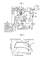
- FIG. 1 is a view for schematically illustrating the system configuration of a first embodiment of the present invention.
- An internal combustion engine 10 illustrated in Fig. 1 includes an internal combustion engine main body 12.
- the internal combustion engine 10 is a spark-ignition type engine (as one example, a gasoline engine), and is mounted in a vehicle and used as a power source of the vehicle.
- An intake passage 14 and an exhaust passage 16 communicate with the respective cylinders of the internal combustion engine main body 12.
- An air cleaner 18 is provided in the vicinity of an inlet of the intake passage 14.
- An air flow sensor 20 that outputs a signal in accordance with a flow rate of air that flows through the intake passage 14 is provided in the air cleaner 18.
- a compressor 22a of a turbosupercharger 22 for supercharging intake air is disposed in the intake passage 14 at a position that is on a downstream side relative to the air cleaner 18.
- the turbosupercharger 22 includes a turbine 22b that is provided in the exhaust passage 16 and that operates by means of the exhaust energy of exhaust gas.
- the compressor 22a is integrally connected to the turbine 22b through a connecting shaft 22c, and is rotationally driven by exhaust energy of exhaust gas that enters the turbine 22b.
- a compressor 24a of an electric supercharger 24 is disposed in the intake passage 14 at a position that is on the downstream side relative to the air cleaner 18 and is on the upstream side relative to the compressor 22a.
- the compressor 24a is driven by an electric motor 24b.
- the electric motor 24b is connected to a battery 26.
- the electric power of the battery 26 is used as the power for driving the electric motor 24b. More specifically, electric power that is generated at an alternator 28 can be supplied to the electric motor 24b directly or through the battery 26.
- the electric supercharger 24 makes it possible to supercharge intake air by driving the compressor 24a using the electric motor 24b.
- the internal combustion engine 10 also includes an intake bypass passage 30 that bypasses the compressor 24a, and an intake bypass valve 32 configured to open and close the intake bypass passage 30. For example, a butterfly-type motor-driven valve can be used as the intake bypass valve 32.
- An intercooler 34 is disposed in the intake passage 14 at a position on the downstream side relative to the compressor 22a.
- the intercooler 34 is used for cooling intake air compressed by the compressor 22a or by both the compressor 22a and the compressor 24a.
- An electronically controlled throttle valve 36 that opens and closes the intake passage 14 is disposed in the intake passage 14 on the downstream side relative to the intercooler 34.
- a portion of the intake passage 14 that is on the downstream side relative to the throttle valve 36 is configured as an intake manifold 38. Intake air is distributed to the respective cylinders through the intake manifold 38.
- An intake air pressure sensor 40 that detects an intake air pressure (more specifically, an intake manifold pressure) is attached to the intake manifold 38.
- Exhaust gas from the respective cylinders is collected by an exhaust manifold 42 in the exhaust passage 16, and discharged to the downstream side.
- An exhaust bypass passage 44 that bypasses the turbine 22b is connected to the exhaust passage 16.
- a waste gate valve (WGV) 46 is disposed in the exhaust bypass passage 44 as a bypass valve for opening and closing the exhaust bypass passage 44.
- the WGV 46 is an electric motor-driven valve, and is configured to be adjustable to an arbitrary opening degree within a predetermined opening degree control range. By changing the opening degree of the WGV 46, the flow rate of exhaust gas that passes through the turbine 22b can be adjusted to thereby adjust the driving force of the compressor 22a.
- a catalyst 48 for purifying exhaust gas is disposed in the exhaust passage 16 at a position on the downstream side relative to the turbine 22b.
- the system of the present embodiment also includes an electronic control unit (ECU) 50.
- the ECU 50 includes at least an input/output interface, a memory, and a central processing unit (CPU).
- the input/output interface is configured to take in sensor signals from various sensors installed in the internal combustion engine 10 or the vehicle in which the internal combustion engine 10 is mounted, and also to output actuating signals to various actuators provided in the internal combustion engine 10.
- the sensors from which the ECU 50 takes in signals include, in addition to the aforementioned air flow sensor 20 and intake air pressure sensor 40, various sensors for acquiring the engine operating state such as a crank angle sensor 52 for acquiring the rotational position of a crankshaft and the engine speed.
- the aforementioned sensors also include an SOC sensor 54 that detects a state-of-charge (SOC) of the battery 26, and an accelerator position sensor 56 for detecting a depression amount of an accelerator pedal (accelerator position) of the vehicle in which the internal combustion engine 10 is mounted.
- SOC state-of-charge
- accelerator position sensor 56 for detecting a depression amount of an accelerator pedal (accelerator position) of the vehicle in which the internal combustion engine 10 is mounted.
- the actuators to which the ECU 50 outputs actuating signals also include various actuators for controlling engine operations such as fuel injection valves 58 for supplying fuel into the combustion chambers of the respective cylinders and an ignition device 60 for igniting an air-to-fuel mixture in the respective combustion chambers.
- Various control programs and maps and the like for controlling the internal combustion engine 10 are stored in the memory.
- the CPU reads out a control program from the memory and executes the control program or the like, and generates actuating signals for the various actuators based on sensor signals taken in.
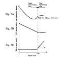
- Fig. 2 is a view for describing the relation between a technique for controlling engine torque that is used in the system illustrated in Fig. 1 and engine operation ranges.
- engine torque control in accordance with the relation illustrated in Fig. 2 is used at a time of steady operation when the internal combustion engine 10 is operating in a steady state.
- the term "steady state" refers to a state in which the engine speed and the engine torque are kept constant with respect to passage of time.
- a configuration may also be adopted so that the engine torque control in accordance with the aforementioned relation is performed in a transient state in which the engine speed and the engine torque change with respect to passage of time.
- a single-supercharging range in which a single-supercharging mode is utilized is set on a high load side (high engine torque side) relative to the WGV fully open range.
- the single-supercharging mode is a supercharging mode that utilizes only the turbosupercharger 22.
- the single-supercharging mode passage of a current to the electric motor 24b is stopped and the intake bypass valve 32 is fully opened.
- intake air that is supercharged by the turbosupercharger 22 utilizing exhaust energy is supplied to the combustion chambers of the respective cylinders while avoiding the occurrence of a situation in which the compressor 24a of the electric supercharger 24 constitutes intake resistance.
- the supercharging pressure is controlled by controlling the opening degree of the WGV 46, and as a result the amount of intake air changes and thus the engine torque is controlled.
- a curve C1 indicated by a solid line in Fig. 2 is a curve that indicates a boundary between the WGV fully open range and the single-supercharging range.
- the curve C1 is a curve that is obtained by connecting engine operating points at which the maximum engine torque (corresponds to a torque boundary value TQ1 that is described later) is realized in a state in which the throttle opening degree has been placed in a fully open state in a WGV fully open range.
- a range located on a high-rotation and high-load side relative to the single-supercharging range is set as a twin-supercharging range in which the twin-supercharging mode is utilized.
- the twin-supercharging mode is a supercharging mode that utilizes the electric supercharger 24 as well as the turbosupercharger 22 in a state in which the throttle valve 36 is kept fully open.
- a current is passed to the electric motor 24b in a state in which the intake bypass valve 32 has basically been fully closed.
- intake air that is introduced into the intake passage 14 is subjected to supercharging by the electric supercharger 24 and the turbosupercharger 22 in that order, and is thereafter supplied to the combustion chambers of the respective cylinders.
- the electric supercharger 24 can be utilized to assist supercharging by the turbosupercharger 22.
- utilization of the electric supercharger 24 to assist supercharging by the turbosupercharger 22 is referred to simply as "electric assist”.
- a curve C2 indicated by a solid line in Fig. 2 is a curve that is obtained by connecting engine operating points at which the maximum engine torque is obtained in a state in which the single-supercharging mode or twin-supercharging mode is utilized.
- a curve C3 indicated by a broken line in Fig. 2 is a curve that indicates a boundary between the single-supercharging range and the twin-supercharging range, and corresponds to the locus of torque boundary values TQ2 (see Figs. 4A to 4C ) on Fig. 2 .
- the single-supercharging mode is used in a high-rotation and high-load range in a state in which the WGV 46 is being closed, the supercharging pressure and the exhaust gas pressure upstream of the turbine will rise, and as a result the temperature of exhaust gas that is discharged from inside the cylinders (hereunder, referred to simply as "exhaust gas temperature”) will rise and pumping loss will also increase. Further, because of the increase in pumping loss, if the single-supercharging mode is used in a torque range in the vicinity of a torque limit in the single-supercharging mode, the fuel efficiency will deteriorate as shown in Fig. 3A that is described later.
- the torque limit in the single-supercharging mode is determined by a constraint that is due to the exhaust gas temperature, the exhaust gas pressure upstream of the turbine, or the pumping loss (corresponds to a "predetermined parameter" in the present invention).
- the torque limit in the single-supercharging mode is determined by the exhaust gas temperature.
- the torque that is a limit under the single-supercharging mode is a value that can be determined, for example, by experiment as an upper limit value of the engine torque that can be obtained utilizing the single-supercharging mode while under the constraint of the aforementioned predetermined parameter such as the exhaust gas temperature.
- the basic advantageous effects obtained by utilizing the twin-supercharging mode (that is, by performing electric assist) will now be described.
- the fuel efficiency will deteriorate if the single-supercharging mode is used in a torque range in the vicinity of a torque limit in the single-supercharging mode.
- the electric supercharger 24 can be caused to perform part of the supercharging that the turbosupercharger 22 would be responsible for if the engine were operating in the single-supercharging mode.
- the load of the turbosupercharger 22 can be reduced, engine torque that is the same as the engine torque in the single-supercharging mode can be realized in a state in which the opening degree of the WGV is a larger degree of opening, and hence an increase in pumping loss that is attributable to an increase in the exhaust gas pressure can be suppressed.
- An increase in the exhaust gas temperature that is attributable to an increase in the exhaust gas pressure can also be suppressed. Therefore, when utilizing a high-rotation and high-load range, an improvement in the fuel efficiency can be achieved by utilizing the electric assist.
- the setting of the WGV opening degree when performing electric assist is important in order to effectively exert a fuel efficiency improvement effect that is produced by utilization of the electric assist.
- a comparative example that will now be described referring to Figs. 3A to 3C is conceivable as a simple technique for controlling the WGV opening degree and the electric motor output in the case of using the twin-supercharging range. That is, in the case of performing electric assist in a high torque range, as illustrated in this comparative example, it is conceivable to perform control so as to reduce the WGV opening degree as the engine torque increases in the single-supercharging range, and in a torque range onwards from a torque value TQ3 that is the value of the engine torque when the WGV opening degree reaches a minimum opening degree that corresponds to a torque limit in the single-supercharging mode, to perform the electric assist while keeping the WGV opening degree constant at the aforementioned minimum opening degree.
- a torque range in the vicinity of the torque limit in the single-supercharging mode is a range in which the fuel efficiency is originally not good, and performing electric assist to reduce the load of the turbosupercharger 22 is basically effective for improving the fuel efficiency.
- a control technique is used that performs electric assist after reaching the torque limit in the single-supercharging mode, as in the comparative example illustrated in Figs. 3A to 3C , in the twin-supercharging range the electric motor output will be increased accompanying an increase in the engine torque while the WGV opening degree remains constant. Consequently, due to an increase in the flow rate of exhaust gas that flows into the turbine 22b, the exhaust gas pressure (exhaust manifold pressure) upstream of the turbine becomes excessively large. Since this fact is related to an increase in pumping loss, an effect of improving the fuel efficiency that is produced by performing the electric assist becomes difficult to be effectively exerted. Further, an increase in the exhaust gas temperature can no longer be suppressed.
- a characteristic of the system of the present embodiment is the technique for controlling the opening degree of the WGV 46 and the output of the electric supercharger 24 in the twin-supercharging range.
- Figs. 4A to 4C are views that represent control characteristics with respect to the opening degree of the WGV 46, the output of the electric motor 24b, and the throttle opening degree, respectively, in respective ranges of the engine torque.
- Figs. 4A to 4C illustrate settings under a condition of an identical engine speed (as one example, an engine speed NE1 shown in Fig. 2 ) in a high engine speed range that utilizes the twin-supercharging mode.
- Fig. 4A illustrates the relation between the engine torque and the WGV opening degree in a steady state
- Fig. 4B illustrates the relation between the engine torque and the electric motor output in a steady state
- a torque range that is lower than the torque boundary value TQ1 corresponds to the aforementioned WGV fully open range
- the throttle opening degree is controlled so as to increase as the engine torque increases.
- the throttle opening degree reaches a fully open opening degree when the engine torque becomes the torque boundary value TQ1.
- a torque range in which the torque is greater than or equal to the torque boundary value TQ1 and less than the torque boundary value TQ2 corresponds to the aforementioned single-supercharging range.
- the throttle opening degree is maintained at the fully open opening degree.
- the WGV opening degree is controlled so as to decrease accompanying an increase in the engine torque in a manner that takes the torque boundary value TQ2 as the upper limit.
- the electric motor output is set to zero (that is, passage of a current to the electric motor 24b is not performed).
- a torque range in which the torque is greater than or equal to the torque boundary value TQ2 corresponds to the aforementioned twin-supercharging range.
- the throttle opening degree is maintained at the fully open opening degree.
- the electric motor output is set to a value P1 at the torque boundary value TQ2.
- the output P1 is an electric motor output that is required in order to exert a compressor rotational speed that is necessary to ensure that the presence of the compressor 24a does not constitute intake resistance under an intake air amount at which the torque boundary value TQ2 is obtained. Furthermore, when the electric motor output becomes higher than P1, the compressor 24a performs work for the outside (that is, starts supercharging).
- the electric motor output becomes higher than P1 when the torque boundary value TQ2 is exceeded, and as a result, supercharging for which the electric supercharger 24 is utilized is added.
- the electric motor output is controlled so that an engine torque can be obtained that matches the engine torque of the horizontal axis in Figs. 4A to 4C under control of the WGV opening degree that is in accordance with the characteristic illustrated in Fig. 4A .
- the electric motor output is controlled so as to increase as the engine torque increases.
- the WGV opening degree is controlled so as to increase as the engine torque increases, in a manner which takes a value WGV1 that is the opening degree at the torque boundary value TQ2 as the minimum value.
- a torque range in which the torque is equal to or greater than the torque boundary value TQ2 corresponds to an "increase range" in the present invention.
- the twin-supercharging range is taken as an "increase range" with regard to the WGV opening degree, and the WGV opening degree is set so as to increase relative to the opening degree WOV1 as the engine torque increases.
- a point of inflection in the control characteristic of the WGV opening degree shown in Fig. 4A (engine operating point at which the torque boundary value TQ2 between the single-supercharging range and the twin-supercharging range is obtained) changes according to the engine speed, as shown by the curve C3 in the engine operation range shown in Fig. 2 .
- the torque boundary value TQ2 is set so as to decrease as the engine speed increases. More specifically, in the present embodiment, the torque boundary value TQ2 is set as an engine torque at which the WGV opening degree (WGV1) is obtained.
- WGV1 is an opening degree at which the exhaust gas temperature reaches a predetermined upper limit temperature in a situation in which the WGV opening degree is decreased as the engine torque increases in the single-supercharging range.
- the engine torque at which the exhaust gas temperature reaches the upper limit temperature decreases as the engine speed increases. Accordingly, when the torque boundary value TQ2 is set from the viewpoint of a constraint that is due to the exhaust gas temperature, the torque boundary value TQ2 decreases as the engine speed increases, as described above. According to this setting, the torque boundary value TQ2 can be appropriately set in a manner that takes the exhaust gas temperature into consideration.
- the WGV opening degree in the twin-supercharging range in Fig. 4A of the present embodiment is set so as to open accompanying an increase in the engine torque in a form in which the exhaust gas temperature is maintained at the above described upper limit temperature. If a setting such that the WGV opening degree changes with a more moderate slope than the setting illustrated in Fig. 4A for which the aforementioned consideration is given with respect to setting of the WGV opening degree is used, the exhaust gas temperature will exceed the upper limit temperature. Conversely, if a setting such that the WGV opening degree changes with a sharper slope than the setting illustrated in Fig.
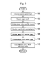
- Fig. 5 is a flowchart illustrating a routine that the ECU 50 executes to control the engine torque.
- Figs. 6A to 6C are views that represent settings of various maps that are calculated in the routine shown in Fig. 5 . Note that the present routine is started during steady operation when the internal combustion engine 10 is in a steady state, and is repeatedly executed for each predetermined control period.
- step 100 the ECU 50 calculates the current required engine torque based on an accelerator position that is detected by the accelerator position sensor 56.
- the ECU 50 proceeds to step 102 to calculate the current engine speed using the crank angle sensor 52.
- a target intake manifold pressure map that is stored in the ECU 50 is a map that defines a target intake manifold pressure based on the relation with the required engine torque and the engine speed. As shown in Fig. 6A , the target intake manifold pressure map is set so that the target intake manifold pressure increases as the required engine torque increases, and so that the target intake manifold pressure increases as the engine speed increases. The ECU 50 refers to this map to acquire a target intake manifold pressure corresponding to the required engine torque and the engine speed acquired in steps 100 and 102.
- the ECU 50 proceeds to step 106 to calculate a target throttle opening degree under the current steady operation based on the required engine torque and the engine speed acquired in steps 100 and 102.
- the ECU 50 stores a map (not illustrated in the drawings) in which the relation between the engine speed and the torque boundary value TQ1 is defined (see the curve C1 in Fig. 2 ), and refers to the map to calculate the torque boundary value TQ1 that corresponds to the current engine speed.
- the ECU 50 sets the fully open opening degree as the target throttle opening degree.
- the ECU 50 calculates the target throttle opening degree as a value that is less than the fully open opening degree in accordance with a map (not illustrated in the drawings) in which the relation between the required engine torque and the engine speed and target throttle opening degree is defined.
- a target WGV opening degree map that the ECU 50 stores defines a target WGV opening degree based on the relation with the target intake manifold pressure and the engine speed.
- the target WGV opening degree is set to a value within a range from a fully open opening degree (maximum opening degree on the opening degree control range) to a fully closed opening degree (minimum opening degree on the opening degree control range) with the relation illustrated in Fig. 6B .
- the intake manifold pressure and the engine torque are in a proportional relation. Therefore, the setting of the map shown in Fig. 6B has a correlation with the control characteristic of the WGV 46 shown in Fig. 4A that is described above.
- a range indicated by hatching in Fig. 6B corresponds to the WGV fully open range shown in Fig. 2 .
- a curve C4 indicated by a broken line in the map in Fig. 6B corresponds to the locus of a point of inflection shown in Fig. 4A (that is, an operating point at which the torque boundary value TQ2 is obtained).
- a range on a low target intake manifold pressure side relative to the curve C4 corresponds to the single-supercharging range.
- a range on a high target intake manifold pressure side relative to the curve C4 corresponds to the twin-supercharging range, and in this range the target WGV opening degree is set so as to increase (become a value further on the open side) as the target intake manifold pressure or the engine speed increases.
- Fig. 6B as one example, the relation between the engine torque and the target intake manifold pressure at the engine speed NE1 shown in Fig. 2 is illustrated.
- Controlling the WGV opening degree so as to become the target WGV opening degree obtained by referring to the map in Fig. 6B that is described above corresponds to controlling the WGV 46 in accordance with the control characteristic shown in Fig. 4A .
- the ECU 50 refers to such a map to acquire a target WGV opening degree that corresponds to the target intake manifold pressure and engine speed acquired in steps 104 and 102.
- a target electric motor output map that the ECU 50 stores is a map which defines the target electric motor output based on the relation with the target intake manifold pressure and the engine speed, and in which the target electric motor output is set based on the relation shown in Fig. 6C in a range corresponding to the twin-supercharging range shown in Fig. 2 .
- a line indicated by "0% output" in the map corresponds to a line at which the external work that the compressor 24a performs changes from zero to a positive amount, and is not a line at which the electric power consumption of the electric motor 24b becomes zero.
- the target electric motor map has a correlation with the control characteristic of the electric motor output that is shown in Fig. 4B . More specifically, the line indicated by "0% output" in the map passes through operating points at which the torque boundary value TQ2 is obtained. Therefore, controlling the electric motor output so as to become the target electric motor output obtained by referring to this map corresponds to controlling the electric motor output in accordance with the control characteristic shown in Fig. 4B .
- the ECU 50 refers to such a map to acquire a target electric motor output that corresponds to the target intake manifold pressure and engine speed acquired in steps 104 and 102.
- step 112 the ECU 50 proceeds to step 112 to control the throttle valve 36, the WGV 46 and the electric motor 24b so as to obtain the target throttle opening degree, the target WGV opening degree and the target electric motor output calculated by the processing in steps 106 to 110.
- the throttle opening degree, the WGV opening degree and the electric motor output can be maintained at values in the vicinity of their respective target values under steady operation.
- TQ2 that is the engine torque that is the limit in the single-supercharging mode is taken as the boundary (torque boundary value) between the single-supercharging range and the twin-supercharging range.
- the engine torque that serves as the above described boundary may be a lower engine torque than TQ2 (for example, TQ4 that is described later).
- turbosupercharger 22 corresponds to “first supercharging means” in the present invention
- electric supercharger 24 corresponds to “second supercharging means” in the present invention
- torque boundary value TQ2 corresponds to "first boundary value” in the present invention
- single-supercharging range corresponds to "first torque index value range” in the present invention
- twin-supercharging range corresponds to "second torque index value range” and "increase range” in the present invention.
- first control means” and “second control means” in the present invention are realized by the ECU 50 executing the processing in step 112.
- a second embodiment of the present invention will be described while newly referring to Figs. 7A to Fig. 9 .
- the present embodiment differs from the first embodiment in the respect that control characteristics shown in Figs. 7A to 7E are used instead of the control characteristics shown in Figs. 4A to 4C in the aforementioned internal combustion engine 10. Further, in the present embodiment, because of utilizing the setting for the torque boundary value TQ4 that is described with reference to Figs. 8A and 8B , electric power that is generated at the alternator 28 in the twin-supercharging range is directly supplied to the electric supercharger 24 while performing the electric power generation.
- Figs. 7A to 7E are views that represent control characteristics with respect to the WGV opening degree and the electric motor output, respectively, that are used in the second embodiment of the present invention.
- the solid lines in Figs. 7A to 7E represent cases in which the twin-supercharging mode is available, and the broken lines in Figs. 7A to 7E represent cases in which the single-supercharging mode is utilized even after exceeding the torque boundary value TQ4.
- the single-supercharging mode may be used in a torque range from the torque boundary value TQ4 to TQ2 that is originally included in the twin-supercharging range.
- a torque limit in the single-supercharging mode is determined based on a constraint with respect to the exhaust gas temperature, similarly to the first embodiment.
- the respective control characteristics of the WGV opening degree and the electric motor output are set as follows to further improve the fuel efficiency in the vicinity of the torque limit in the single-supercharging mode. That is, as shown in Fig. 7B , with respect to the control characteristic for the electric motor output, the engine torque TQ4 that is lower than TQ2 that is the limit torque in the single-supercharging mode is taken as the boundary (torque boundary value) between the single-supercharging range and the twin-supercharging range.
- the electric motor output is controlled so that, at a value that can produce an engine torque that matches the engine torque of the horizontal axis in Figs. 7A to 7E under the control characteristic for the WGV opening degree shown in Fig. 7A , the electric motor output increases as the engine torque increases.
- the control characteristic of the WGV opening degree includes, on a high torque side relative to the torque boundary value TQ4, a "constant range (TQ4 to TQ5)" in which the WGV opening degree is kept constant with respect to a change in the engine torque.
- an engine torque (torque boundary value) TQ5 that is the upper limit of the "constant range” corresponds to an engine torque value when the exhaust gas temperature reaches the upper limit temperature at a time when the electric motor output is increased while keeping the WGV opening degree constant.
- the aforementioned "constant range” is not limited to a range in which the WGV opening degree is kept strictly constant with respect to a change in the engine torque, and may be a range in which the WGV opening degree is kept substantially constant with respect to a change in the engine torque.
- a range on a high torque side relative to the torque boundary value TQ5 is set as an "increase range" in which the WGV opening degree increases accompanying an increase in the engine torque. More specifically, the setting of the WGV opening degree in this range is based on the same concept as the setting of the WGV opening degree in the "increase range" on the higher torque side than the torque boundary value TQ2 in the control characteristic shown in Fig. 4A of the first embodiment. That is, a WGV opening degree that is necessary for maintaining the exhaust gas temperature at the upper limit temperature is selected, and an electric motor output that is necessary for generating an engine torque that matches the engine torque of the horizontal axis in Figs. 7A to 7E under the selected WGV opening degree is selected.
- the ignition timing can be prevented from being retarded for suppressing the occurrence of knocking or at least the amount of the retard can be reduced. Accordingly, in the torque range (TQ4 to TQ2), as shown in Fig. 7D the ignition timing can be advanced in comparison to that for the single-supercharging mode.
- the ignition timing at the respective engine torques in the aforementioned torque range is advanced in comparison to a case where utilization of the electric assist is restricted (that is, a case where it is necessary to utilize the single-supercharging mode).
- the torque boundary value TQ4 at the boundary between the single-supercharging range and the twin-supercharging range can be set, for example, by a technique that is described hereunder with reference to Figs. 8A and 8B .
- the technique for setting the torque boundary value TQ4 is not necessarily limited to the technique described below and, for example, as the control characteristic shown in Figs. 7A to 7E ultimately becomes, the torque boundary value TQ4 may be an engine torque value in the vicinity of a value at which the fuel consumption amount becomes lowest when using the single-supercharging mode.
- the setting technique described below is an effective technique for improving fuel efficiency in the case of adopting a configuration that, similarly to the system of the present embodiment, performs electric assist by directly utilizing electric power generated by the alternator 28.
- Figs. 8A and 8B are views that are used for describing a technique for setting the torque boundary value TQ4 from the viewpoint of optimizing fuel efficiency.
- Each of the relations shown in Figs. 8A and 8B is one that assumes an engine operation range on a high-rotation and high-load range that requires supercharging at a time of steady operation.
- Fig. 8A is a view that represents a relation between a fuel consumption amount and the electric power consumption of the electric motor 24b under a condition in which it is assumed that fuel is used to generate engine torque and is not used to generate electric power to be consumed by the electric supercharger 24.
- a condition corresponds to, for example, a time when electric power that is charged in the battery 26 when the engine operating point is in the WGV fully open range is used, or a time when electric power that is supplied to the battery 26 from outside the vehicle is used, in order to perform electric assist.
- the fuel consumption amount decreases as the electric power consumption of the electric motor 24b increases.
- the reason is as follows. Namely, when the turbosupercharger 22 is caused to perform work for supercharging, the exhaust gas pressure increases upstream of the turbine, and this leads to an increase in the pumping loss. In contrast, if work that the turbosupercharger 22 is responsible for is allocated to the electric supercharger 24, a decrease in the pumping loss can be achieved by reducing the work of the turbosupercharger 22. Therefore, the greater the electric power consumption of the electric motor 24b is (that is, the greater the workload that the electric supercharger 24 is responsible for), the less that the fuel consumption amount becomes.
- Fig. 8B illustrates a case where electric power generated by the alternator 28 is supplied directly to the electric motor 24b without passing through the battery 26, and electric assist is performed.
- a solid line in Fig. 8B and a solid line in Fig. 8A represent states under conditions in which the engine torque and the engine speed are the same.
- the case represented by the solid line in Fig. 8B is not a case in which the fuel consumption amount uniformly decreases as the electric power consumption increases.
- the fuel consumption amount increases because an increase in the consumption of fuel that is required to generate electric power necessary for the electric assist acts to negate the effect of suppressing the fuel consumption by performing the electric assist.
- a waveform in which the minimum point of the fuel consumption amount exists such as the waveform shown by the solid line in Fig. 8B is a waveform at an operating point at which a waveform that is below a straight line L shown in Fig. 8B is obtained, and is not a waveform obtained at merely any operating point within the supercharging range. More specifically, the waveform indicated by the broken line in Fig. 8B is a waveform at an operating point at which the engine torque is low in comparison to the waveform indicated by solid line in the same figure. At such operating point, an advantage of a reduction in the fuel consumption amount is not obtained even if electric assist is performed, and hence it is preferable not to use electric assist in terms of the fuel consumption amount.
- the waveform changes in the direction toward the solid line from the broken line in Fig. 8B as the engine torque increases.
- a waveform that is below the straight line L is obtained in the course of this change. Accordingly, if the engine torque at which such a waveform is obtained is taken as the torque boundary value TQ4 and a configuration is adopted so that electric assist is performed when the engine torque is equal to or greater than the torque boundary value TQ4, electric assist can be performed in a manner such that the fuel consumption amount decreases even when the electric power consumption of the electric motor 24b is taken into consideration.
- the torque boundary value TQ4 adopting an engine torque at which a waveform that is below the straight line L is obtained as the torque boundary value TQ4 is preferable from the viewpoint of reducing the fuel consumption amount. Further, the torque boundary value TQ4 that is determined from this viewpoint changes as the engine speed changes, and, more specifically, becomes lower as the engine speed increases. Therefore, with regard to a tendency of a change with respect to the engine speed, the torque boundary value TQ4 changes in a similar manner to the torque boundary value TQ2 that is used in the first embodiment.
- the torque boundary value TQ4 By determining the torque boundary value TQ4 having this characteristic in advance and mapping the relation between the torque boundary value TQ4 and the engine speed, the torque boundary value TQ4 that corresponds to the lower limit of the engine torque at which performance of electric assist is preferable from the viewpoint of improving the fuel efficiency can be identified within the engine operation range.
- a value (minimum fuel consumption electric power value) of the electric power consumption at which the minimum point is obtained changes accompanying a change in the engine torque and engine speed.
- the waveform of the electric motor output (electric power consumption) shown in Fig. 7B corresponds to a waveform that is obtained by connecting minimum fuel consumption electric power values corresponding to respective engine torques under an identical engine speed. That is, the idea described above referring to Fig. 8B is reflected in the control characteristic of the electric motor output shown in Fig. 7B .
- a "constant range” is provided in which the WGV opening degree is kept constant at a WGV opening degree that corresponds to an engine torque that is lower than a limit torque in the single-supercharging mode (in other words, a WGV opening degree that is greater than the WGV opening degree corresponding to the limit torque).
- an "increase range” in which the WGV opening degree increases as the engine torque increases is provided as a torque range that continues from the "constant range”.
- electric assist is performed on the higher torque side relative to the torque boundary value TQ4 in the control characteristic shown in Fig. 7B .
- an improvement in the fuel efficiency can be achieved by setting the torque boundary value TQ4 within the low fuel consumption range that exists on the low torque side relative to the limit torque in the single-supercharging mode. Further, the effect of such an improvement in the fuel efficiency can be obtained more effectively by adding the setting of the torque boundary value TQ4 that takes the optimization of fuel efficiency into consideration that is shown in Fig. 8B .
- the WGV opening degree in a high torque range that is a range such as one in which a constant range is set
- setting the WGV opening degree so as to exceed a constant or a substantially constant range and decrease as the engine torque increases even when the rate of decrease is moderate relative to the rate of a change in the WGV opening degree with respect to a change in the engine torque in the single-supercharging range will lead to an increase in the pumping loss. Therefore, from the viewpoint of improving fuel efficiency also, it is favorable to make such a high torque range a "constant range".
- the ignition timings at the respective engine torques are advanced in the aforementioned torque range in comparison to a case in which utilization of the electric assist is restricted (that is, a case where it is necessary to utilize the single-supercharging mode).
- the fuel efficiency in the aforementioned torque range is improved more effectively by the action of advancing the ignition timing in this manner.
- advancement of the ignition timing makes it possible to increase the generated engine torque in comparison to a case where such advancement is not performed, the electric motor output that is required to realize the same engine torque can be reduced.
- Control by the ECU 50 for controlling the engine torque utilizing the control characteristics shown in Figs. 7A to 7E at a time of steady operation can be realized by causing the ECU 50 to execute the similar processing as in the routine shown in Fig. 5 after replacing the target WGV opening degree map and the target electric motor output map that are shown in Figs. 6A to 6C with maps in which the steady-state characteristics shown in Figs. 7A to 7E have been reflected.
- Fig. 9 is a flowchart illustrating a routine that the ECU 50 executes to realize the above described ignition timing control in the torque range from TQ4 to TQ2. Note that the present routine is repeatedly executed for each predetermined control period.
- step 200 the ECU 50 determines whether or not the current required torque is within the torque range from TQ4 to TQ2.
- the ECU 50 proceeds to step 202 to determine whether or not it is possible to use the electric supercharger 24. For example, a case where the necessity has arisen to give priority to a device other than the electric supercharger 24 with respect to the use of electric power generated at the alternator 28 because the amount of power stored in the battery 26 that is detected by the SOC sensor 54 is lower than a predetermined level corresponds to a case where utilization of the electric supercharger 24 is restricted.
- utilization of the electric supercharger 24 is restricted due to a constraint from the viewpoint of the temperature of the electric motor 24b.
- waveforms indicated by broken lines in Fig. 7A and 7C to 7E are applied, and the engine torque value TQ2 that is the upper limit value of the engine torque in this case corresponds to "upper limit of a torque index value" in the present invention.
- the WGV opening degree that is used in the constant range when using the twin-supercharging mode becomes larger than the WGV opening degree in a case where the single-supercharging mode is selected in the torque range of torque values equal to and greater than the torque boundary value TQ4.
- step 204 a retard map is used for the ignition timing control.
- the term "retard map” refers to a map that defines the basic ignition timing based on a relation with the required engine torque and the engine speed while taking into consideration suppressing the occurrence of knocking in the torque range from TQ4 to TQ2 under the single-supercharging mode.
- step 206 an advance map is used for the ignition timing control.
- the term "advance map” refers to a map that defines the basic ignition timing based on a relation with the required engine torque and the engine speed while taking into consideration suppressing the occurrence of knocking in the torque range from TQ4 to TQ2 under the twin-supercharging mode.
- the ignition timing can be prevented from being retarded for suppressing the occurrence of knocking or at least the amount of the retard can be reduced. Therefore, with regard to the same engine operating point in a high-load and high-rotation range in which the occurrence of knocking is a concern, the basic ignition timing defined by the advance map is set to a value that is further on an advance side than the basic ignition timing defined by the retard map.
- the ignition timing control in the present embodiment is control that takes, as a basis, a control based on a basic ignition timing which is in accordance with the retard map or advance map selected depending on whether or not it is possible to use the electric supercharger 24, and that is accompanied by execution of a general optimal ignition timing control.
- the aforementioned optimal ignition timing control is control that causes the ignition timing to approach as much as possible the optimal ignition timing while correcting the ignition timing so that the occurrence frequency of knocking and the knocking intensity do not exceed the reference values by using a knock sensor (not illustrated in the drawings) for detecting knocking.
- TQ4 that is a lower engine torque than the limit torque that is determined by a constraint of the exhaust gas temperature when using the single-supercharging mode is taken as the boundary (torque boundary value) between the single-supercharging range and the twin-supercharging range.
- the aforementioned boundary that corresponds to a "first boundary value" in the present invention may be determined by a constraint of a predetermined parameter other than the exhaust gas temperature.
- the predetermined parameter may be an exhaust gas pressure upstream of the turbine or a pumping loss of the internal combustion engine.
- the torque boundary value TQ4 corresponds to "first boundary value” in the present invention
- the torque boundary value TQ5 corresponds to "second boundary value” in the present invention
- the single-supercharging mode corresponds to "non-motor assisted supercharging mode” in the present invention
- the twin-supercharging mode corresponds to "motor assisted supercharging mode” in the present invention.
- ignition timing control means in the present invention is realized by the ECU 50 executing the processing in step 206 in a case where the respective results determined in steps 200 and 202 are both affirmative.
- the lower limit (also corresponds to the boundary between the single-supercharging range and the twin-supercharging range in the case of the first embodiment) of the "increase range" with regard to the WGV opening degree is set at the torque boundary value TQ2 from the viewpoint of the exhaust gas temperature
- the lower limit of the "increase range” is set to the torque boundary value TQ5 that is the engine torque at which the exhaust gas temperature reaches the upper limit temperature when using the twin-supercharging mode.
- an engine torque that serves as the lower limit of the "increase range” is set based on the exhaust gas temperature.
- a lower limit of the "increase range" in the present invention is not limited to a value that is set based on the exhaust gas temperature, and for example the lower limit may be set based on an exhaust gas pressure upstream of the turbine or a pumping loss of the internal combustion engine. More specifically, in the case of the first embodiment, instead of the torque boundary value TQ2, a torque boundary value TQ2' that is determined by taking into consideration a constraint from the viewpoint of the exhaust gas pressure upstream of the turbine or the pumping loss may be set as the lower limit of the "increase range".
- a torque boundary value TQ5' that is determined by taking into consideration a constraint from the viewpoint of the exhaust gas pressure upstream of the turbine or the pumping loss may be set as the lower limit of the "increase range".
- the torque index value may be a value other than the engine torque, for example, an intake air pressure, an engine load factor or an intake air amount.
- an internal combustion engine 10 including the turbosupercharger 22 and the electric supercharger 24 in a configuration in which the compressor 24a is provided in series in the intake passage 14 on the upstream side with respect to the compressor 22a.
- an internal combustion engine that is an object of the present invention may include a compressor of a turbosupercharger and a compressor of an electric supercharger that are provided in parallel in an intake passage, or may include a compressor of an electric supercharger in an intake passage on a downstream side relative to the compressor of a turbosupercharger.
- an electric supercharger that is provided separately to a turbosupercharger may be an electric-motor-assisted turbosupercharger.
- first and second embodiments have been described taking the internal combustion engine 10 including the turbosupercharger 22 and the electric supercharger 24 as an example.
- first supercharging means and “second supercharging means” in the present invention may be realized by a single electric-motor-assisted turbosupercharger instead of by the configuration described above.
- a turbosupercharger that has a configuration which includes a turbine arranged in an exhaust passage, a compressor arranged in an intake passage and an electric motor arranged between the turbine and the compressor (that is, a configuration in which a connecting shaft that connects the turbine with the compressor functions as a rotor of the electric motor) and that is configured to drive the compressor by actuating the electric motor corresponds to the electric-motor-assisted turbosupercharger.
- the electric motor that the electric-motor-assisted turbosupercharger includes may be controlled utilizing a control characteristic that is based on the same idea as the control characteristic shown in Fig. 4B or Fig. 7B
- the waste gate valve may be controlled utilizing a control characteristic that is based on the same idea as the control characteristic shown in Fig. 4A or Fig. 7A .
- control that takes a gasoline engine that is a spark-ignition type engine as an object is described in the first and second embodiments, with the exception of the above described ignition timing control, the control of the present invention may also be applied to a compression-ignition type engine such as a diesel engine.
Applications Claiming Priority (2)
| Application Number | Priority Date | Filing Date | Title |
|---|---|---|---|
| JP2014185610 | 2014-09-11 | ||
| JP2015106509A JP5991405B2 (ja) | 2014-09-11 | 2015-05-26 | 内燃機関の制御装置 |
Publications (1)
| Publication Number | Publication Date |
|---|---|
| EP2995798A1 true EP2995798A1 (de) | 2016-03-16 |
Family
ID=54014616
Family Applications (1)
| Application Number | Title | Priority Date | Filing Date |
|---|---|---|---|
| EP15183088.2A Withdrawn EP2995798A1 (de) | 2014-09-11 | 2015-08-31 | Steuerungsvorrichtung für einen verbrennungsmotor |
Country Status (3)
| Country | Link |
|---|---|
| US (1) | US10006350B2 (de) |
| EP (1) | EP2995798A1 (de) |
| CN (1) | CN105422267B (de) |
Cited By (4)
| Publication number | Priority date | Publication date | Assignee | Title |
|---|---|---|---|---|
| US20170002726A1 (en) * | 2015-07-01 | 2017-01-05 | Toyota Jidosha Kabushiki Kaisha | Control apparatus for internal combustion engine |
| WO2019016439A1 (fr) * | 2017-07-18 | 2019-01-24 | Psa Automobiles Sa | Groupe motopropulseur avec maintien en opération d'un compresseur auxiliaire en phase de pleine puissance |
| EP3626947A1 (de) * | 2018-09-24 | 2020-03-25 | Pratt & Whitney Canada Corp. | System und verfahren zur bestimmung der beschleunigung einer welle |
| US10985608B2 (en) | 2016-12-13 | 2021-04-20 | General Electric Company | Back-up power system for a component and method of assembling same |
Families Citing this family (21)
| Publication number | Priority date | Publication date | Assignee | Title |
|---|---|---|---|---|
| JP6036677B2 (ja) * | 2013-12-26 | 2016-11-30 | トヨタ自動車株式会社 | 電動ウェイストゲートバルブシステム |
| EP2995798A1 (de) * | 2014-09-11 | 2016-03-16 | Toyota Jidosha Kabushiki Kaisha | Steuerungsvorrichtung für einen verbrennungsmotor |
| WO2016132455A1 (ja) * | 2015-02-17 | 2016-08-25 | ボルボ トラック コーポレーション | 電動過給システム及び電動過給機の制御方法 |
| JP6248993B2 (ja) * | 2015-07-31 | 2017-12-20 | トヨタ自動車株式会社 | 内燃機関の制御装置 |
| KR101714265B1 (ko) * | 2015-11-30 | 2017-03-23 | 현대자동차주식회사 | 수퍼차저가 장착된 엔진시스템의 제어방법 |
| JP6280537B2 (ja) * | 2015-12-25 | 2018-02-14 | 本田技研工業株式会社 | 内燃機関の制御装置 |
| GB201617825D0 (en) * | 2016-10-21 | 2016-12-07 | Ford Global Tech Llc | A boosted engine system of a motor vehicle |
| US10190483B2 (en) * | 2016-11-23 | 2019-01-29 | GM Global Technology Operations LLC | Method of controlling a pressure ratio in a flow of compressed combustion air |
| US10508590B2 (en) | 2017-02-07 | 2019-12-17 | Kohler Co. | Forced induction engine with electric motor for compressor |
| US10815875B2 (en) * | 2017-03-30 | 2020-10-27 | Ford Global Technologies, Llc | Method and system for boosted engine system |
| JP6416310B1 (ja) * | 2017-04-17 | 2018-10-31 | 三菱電機株式会社 | 内燃機関の制御装置及び制御方法 |
| DE102017004184A1 (de) * | 2017-04-29 | 2018-10-31 | Daimler Ag | Verbrennungskraftmaschine für ein Kraftfahrzeug, insbesondere für einen Kraftwagen |
| US10352189B2 (en) * | 2017-05-10 | 2019-07-16 | Pratt & Whitney Canada Corp. | Method and system for setting an acceleration schedule for engine start |
| CN109458255A (zh) * | 2017-09-06 | 2019-03-12 | 上汽通用汽车有限公司 | 汽油机复合增压系统控制方法以及汽油机复合增压系统 |
| EP3737845A1 (de) * | 2018-01-11 | 2020-11-18 | Ai Alpine Us Bidco Inc. | Hubkolbenmotorsystem mit elektrisch angetriebenem verdichter und verfahren zum betrieb desselben |
| JP7131983B2 (ja) * | 2018-06-25 | 2022-09-06 | 株式会社ジャパンエンジンコーポレーション | 舶用内燃機関 |
| US11408359B2 (en) | 2020-08-31 | 2022-08-09 | Garrett Transportation I Inc. | System for turbocharger performance monitoring and adaptation |
| US11624332B2 (en) * | 2020-08-31 | 2023-04-11 | Garrett Transportation I Inc. | Control system with diagnostics monitoring for engine control |
| US11530656B2 (en) | 2020-08-31 | 2022-12-20 | Garrett Transportation I Inc. | Health conscious controller |
| US11687071B2 (en) | 2021-08-19 | 2023-06-27 | Garrett Transportation I Inc. | Methods of health degradation estimation and fault isolation for system health monitoring |
| US11732670B2 (en) | 2021-11-12 | 2023-08-22 | Garrett Transportation I Inc. | System and method for on-line recalibration of control systems |
Citations (5)
| Publication number | Priority date | Publication date | Assignee | Title |
|---|---|---|---|---|
| JPS57212331A (en) * | 1981-06-22 | 1982-12-27 | Hitachi Ltd | Turbocharger |
| CA1188168A (en) * | 1981-09-22 | 1985-06-04 | Peter Moser | Internal combustion engine having variable exhaust intake turbocharger |
| EP1749990A2 (de) * | 2005-08-03 | 2007-02-07 | HONDA MOTOR CO., Ltd. | Brennkraftmaschine mit Turbolader |
| JP2012067698A (ja) * | 2010-09-24 | 2012-04-05 | Toyota Motor Corp | ウエストゲートバルブ装置 |
| JP2014015846A (ja) | 2012-07-05 | 2014-01-30 | Toyota Motor Corp | 過給機付内燃機関の制御装置、過給機付内燃機関を搭載した車両 |
Family Cites Families (28)
| Publication number | Priority date | Publication date | Assignee | Title |
|---|---|---|---|---|
| US6928819B2 (en) * | 2002-01-31 | 2005-08-16 | Robert Bosch Gmbh | Method and arrangement for controlling the charge pressure of an exhaust-gas turbocharger |
| JP3969314B2 (ja) * | 2003-01-30 | 2007-09-05 | 日産自動車株式会社 | 過給装置 |
| JP4306483B2 (ja) * | 2004-02-10 | 2009-08-05 | トヨタ自動車株式会社 | 電動機付過給機を有する内燃機関の制御装置 |
| US20080053091A1 (en) * | 2005-02-16 | 2008-03-06 | Pierre Barthelet | Turbocharging Device and Control Method for Controlling the Turbocharging Device |
| US7921944B2 (en) * | 2007-10-29 | 2011-04-12 | Ford Global Technologies, Llc | Compression system for internal combustion engine including a rotationally uncoupled exhaust gas turbine |
| JP2009191686A (ja) | 2008-02-13 | 2009-08-27 | Mazda Motor Corp | エンジンの過給装置 |
| JP2010249019A (ja) * | 2009-04-15 | 2010-11-04 | Mitsubishi Electric Corp | 内燃機関 |
| JP5874161B2 (ja) * | 2010-10-28 | 2016-03-02 | いすゞ自動車株式会社 | ターボ過給システム |
| JP2012097606A (ja) * | 2010-10-29 | 2012-05-24 | Isuzu Motors Ltd | ターボ過給システム |
| CN103443417B (zh) * | 2011-04-08 | 2016-03-16 | 株式会社Ihi | 电动辅助增压机及其控制方法 |
| GB2492354A (en) * | 2011-06-28 | 2013-01-02 | Gm Global Tech Operations Inc | Operating an i.c. engine having an electrically driven charge air compressor |
| US9528432B2 (en) * | 2011-09-25 | 2016-12-27 | Cummins, Inc. | System for controlling an air handling system including an electric motor assisted variable geometry turbocharger |
| JP5243637B1 (ja) | 2012-03-29 | 2013-07-24 | 三菱電機株式会社 | 内燃機関システム |
| JP5554391B2 (ja) * | 2012-12-13 | 2014-07-23 | 三菱電機株式会社 | 排ガス発電機を備えたハイブリッド車両の制御装置および排ガス発電機を備えたハイブリッド車両の制御方法 |
| KR101427968B1 (ko) * | 2013-02-06 | 2014-08-08 | 현대자동차 주식회사 | 엔진의 제어방법 |
| US9010114B2 (en) * | 2013-02-19 | 2015-04-21 | The Boeing Company | Air charge system and method for an internal combustion engine |
| CN105229287B (zh) * | 2013-05-14 | 2018-04-20 | 丰田自动车株式会社 | 内燃机的控制装置 |
| JP2016011641A (ja) * | 2014-06-30 | 2016-01-21 | トヨタ自動車株式会社 | 過給システム |
| EP2995798A1 (de) * | 2014-09-11 | 2016-03-16 | Toyota Jidosha Kabushiki Kaisha | Steuerungsvorrichtung für einen verbrennungsmotor |
| US9540989B2 (en) * | 2015-02-11 | 2017-01-10 | Ford Global Technologies, Llc | Methods and systems for boost control |
| JP6245221B2 (ja) * | 2015-06-01 | 2017-12-13 | トヨタ自動車株式会社 | 内燃機関の制御装置 |
| JP6248993B2 (ja) * | 2015-07-31 | 2017-12-20 | トヨタ自動車株式会社 | 内燃機関の制御装置 |
| GB2541382A (en) * | 2015-08-14 | 2017-02-22 | Ford Global Tech Llc | Improvements in or relating to twin charged engines |
| JP5944037B1 (ja) * | 2015-08-21 | 2016-07-05 | 三菱電機株式会社 | 過給機付き内燃機関の制御装置 |
| US9726092B2 (en) * | 2015-11-16 | 2017-08-08 | Ford Global Technologies, Llc | Methods and systems for boost control |
| JP6322618B2 (ja) * | 2015-12-07 | 2018-05-09 | 本田技研工業株式会社 | 内燃機関の制御装置 |
| JP6280537B2 (ja) * | 2015-12-25 | 2018-02-14 | 本田技研工業株式会社 | 内燃機関の制御装置 |
| US10323564B2 (en) * | 2016-01-19 | 2019-06-18 | GM Global Technology Operations LLC | Systems and methods for increasing temperature of an internal combustion engine during a cold start including low coolant flow rates during a startup period |
-
2015
- 2015-08-31 EP EP15183088.2A patent/EP2995798A1/de not_active Withdrawn
- 2015-09-09 US US14/849,171 patent/US10006350B2/en not_active Expired - Fee Related
- 2015-09-11 CN CN201510577895.XA patent/CN105422267B/zh not_active Expired - Fee Related
Patent Citations (5)
| Publication number | Priority date | Publication date | Assignee | Title |
|---|---|---|---|---|
| JPS57212331A (en) * | 1981-06-22 | 1982-12-27 | Hitachi Ltd | Turbocharger |
| CA1188168A (en) * | 1981-09-22 | 1985-06-04 | Peter Moser | Internal combustion engine having variable exhaust intake turbocharger |
| EP1749990A2 (de) * | 2005-08-03 | 2007-02-07 | HONDA MOTOR CO., Ltd. | Brennkraftmaschine mit Turbolader |
| JP2012067698A (ja) * | 2010-09-24 | 2012-04-05 | Toyota Motor Corp | ウエストゲートバルブ装置 |
| JP2014015846A (ja) | 2012-07-05 | 2014-01-30 | Toyota Motor Corp | 過給機付内燃機関の制御装置、過給機付内燃機関を搭載した車両 |
Cited By (6)
| Publication number | Priority date | Publication date | Assignee | Title |
|---|---|---|---|---|
| US20170002726A1 (en) * | 2015-07-01 | 2017-01-05 | Toyota Jidosha Kabushiki Kaisha | Control apparatus for internal combustion engine |
| US10132231B2 (en) * | 2015-07-01 | 2018-11-20 | Toyota Jidosha Kabushiki Kaisha | Control apparatus for internal combustion engine |
| US10985608B2 (en) | 2016-12-13 | 2021-04-20 | General Electric Company | Back-up power system for a component and method of assembling same |
| WO2019016439A1 (fr) * | 2017-07-18 | 2019-01-24 | Psa Automobiles Sa | Groupe motopropulseur avec maintien en opération d'un compresseur auxiliaire en phase de pleine puissance |
| FR3069283A1 (fr) * | 2017-07-18 | 2019-01-25 | Psa Automobiles Sa | Groupe motopropulseur avec maintien en operation d’un compresseur auxiliaire en phase de pleine puissance |
| EP3626947A1 (de) * | 2018-09-24 | 2020-03-25 | Pratt & Whitney Canada Corp. | System und verfahren zur bestimmung der beschleunigung einer welle |
Also Published As
| Publication number | Publication date |
|---|---|
| US10006350B2 (en) | 2018-06-26 |
| US20160076438A1 (en) | 2016-03-17 |
| CN105422267B (zh) | 2018-04-20 |
| CN105422267A (zh) | 2016-03-23 |
Similar Documents
| Publication | Publication Date | Title |
|---|---|---|
| US10006350B2 (en) | Control apparatus for internal combustion engine | |
| EP3103991B1 (de) | Steuerungsvorrichtung für einen verbrennungsmotor | |
| US8086385B2 (en) | Control apparatus for internal combustion engine | |
| JP5389238B1 (ja) | 内燃機関のウェイストゲートバルブ制御装置 | |
| US9695771B2 (en) | Spark and valve control for different air/fuel ratios | |
| KR101826551B1 (ko) | 엔진 제어 장치 및 방법 | |
| CN106939845B (zh) | 内燃机的控制装置 | |
| JP6661593B2 (ja) | 内燃機関の制御装置 | |
| JP5991405B2 (ja) | 内燃機関の制御装置 | |
| JP6691498B2 (ja) | 内燃機関の制御装置 | |
| JP5531987B2 (ja) | 過給機付き内燃機関の制御装置 | |
| JP4627432B2 (ja) | 過給機付き内燃機関の制御装置 | |
| EP3006702A1 (de) | Verbrennungsmotor und steuerungsverfahren dafür | |
| JP4953100B2 (ja) | ターボチャージャ付き内燃機関 | |
| JP6127906B2 (ja) | 内燃機関の制御装置 | |
| JP2006125352A (ja) | 過給機付き内燃機関の制御装置 | |
| JP5338709B2 (ja) | 内燃機関の制御装置 | |
| JP5263249B2 (ja) | 過給機付き内燃機関の可変バルブタイミング制御装置 | |
| CN110080889B (zh) | 内燃机的控制装置 | |
| JP2010261358A (ja) | 内燃機関の制御装置 | |
| JP6432548B2 (ja) | エンジンの制御装置 | |
| JP2006070751A (ja) | 内燃機関の制御装置 | |
| JP2004278348A (ja) | 内燃機関の制御装置 | |
| JP2018178967A (ja) | 内燃機関の制御装置 |
Legal Events
| Date | Code | Title | Description |
|---|---|---|---|
| PUAI | Public reference made under article 153(3) epc to a published international application that has entered the european phase |
Free format text: ORIGINAL CODE: 0009012 |
|
| 17P | Request for examination filed |
Effective date: 20150831 |
|
| AK | Designated contracting states |
Kind code of ref document: A1 Designated state(s): AL AT BE BG CH CY CZ DE DK EE ES FI FR GB GR HR HU IE IS IT LI LT LU LV MC MK MT NL NO PL PT RO RS SE SI SK SM TR |
|
| AX | Request for extension of the european patent |
Extension state: BA ME |
|
| STAA | Information on the status of an ep patent application or granted ep patent |
Free format text: STATUS: THE APPLICATION HAS BEEN WITHDRAWN |
|
| 18W | Application withdrawn |
Effective date: 20160804 |