EP2989649B1 - Methods for solid electrolyte interphase formation and anode pre-lithiation of lithium ion capacitors - Google Patents
Methods for solid electrolyte interphase formation and anode pre-lithiation of lithium ion capacitors Download PDFInfo
- Publication number
- EP2989649B1 EP2989649B1 EP14727297.5A EP14727297A EP2989649B1 EP 2989649 B1 EP2989649 B1 EP 2989649B1 EP 14727297 A EP14727297 A EP 14727297A EP 2989649 B1 EP2989649 B1 EP 2989649B1
- Authority
- EP
- European Patent Office
- Prior art keywords
- anode
- dopant source
- lithium ion
- doping
- electrolyte
- Prior art date
- Legal status (The legal status is an assumption and is not a legal conclusion. Google has not performed a legal analysis and makes no representation as to the accuracy of the status listed.)
- Active
Links
- HBBGRARXTFLTSG-UHFFFAOYSA-N Lithium ion Chemical compound [Li+] HBBGRARXTFLTSG-UHFFFAOYSA-N 0.000 title claims description 148
- 229910001416 lithium ion Inorganic materials 0.000 title claims description 148
- 239000003990 capacitor Substances 0.000 title claims description 128
- 238000000034 method Methods 0.000 title claims description 85
- 239000007784 solid electrolyte Substances 0.000 title claims description 63
- 230000016507 interphase Effects 0.000 title claims description 62
- 230000015572 biosynthetic process Effects 0.000 title claims description 59
- 238000006138 lithiation reaction Methods 0.000 title description 19
- 239000002019 doping agent Substances 0.000 claims description 130
- 239000003792 electrolyte Substances 0.000 claims description 33
- OKTJSMMVPCPJKN-UHFFFAOYSA-N Carbon Chemical compound [C] OKTJSMMVPCPJKN-UHFFFAOYSA-N 0.000 claims description 14
- 230000008878 coupling Effects 0.000 claims description 14
- 238000010168 coupling process Methods 0.000 claims description 14
- 238000005859 coupling reaction Methods 0.000 claims description 14
- 238000004146 energy storage Methods 0.000 claims description 8
- 229910002804 graphite Inorganic materials 0.000 claims description 4
- 239000010439 graphite Substances 0.000 claims description 4
- 230000008569 process Effects 0.000 description 53
- 230000001351 cycling effect Effects 0.000 description 22
- 229910052744 lithium Inorganic materials 0.000 description 14
- 230000035699 permeability Effects 0.000 description 12
- 230000003247 decreasing effect Effects 0.000 description 11
- 239000011230 binding agent Substances 0.000 description 9
- -1 hexafluorophosphate Chemical compound 0.000 description 8
- 239000000463 material Substances 0.000 description 8
- 239000000654 additive Substances 0.000 description 7
- 230000000996 additive effect Effects 0.000 description 7
- 230000008901 benefit Effects 0.000 description 7
- 238000010348 incorporation Methods 0.000 description 7
- 239000000203 mixture Substances 0.000 description 6
- 150000003839 salts Chemical class 0.000 description 6
- 239000002904 solvent Substances 0.000 description 6
- 239000002482 conductive additive Substances 0.000 description 5
- 229920000642 polymer Polymers 0.000 description 5
- 239000000126 substance Substances 0.000 description 5
- WHXSMMKQMYFTQS-UHFFFAOYSA-N Lithium Chemical compound [Li] WHXSMMKQMYFTQS-UHFFFAOYSA-N 0.000 description 4
- 230000001747 exhibiting effect Effects 0.000 description 4
- 230000006872 improvement Effects 0.000 description 4
- 229920001343 polytetrafluoroethylene Polymers 0.000 description 4
- 239000004810 polytetrafluoroethylene Substances 0.000 description 4
- 230000006641 stabilisation Effects 0.000 description 4
- 238000011105 stabilization Methods 0.000 description 4
- WEVYAHXRMPXWCK-UHFFFAOYSA-N Acetonitrile Chemical compound CC#N WEVYAHXRMPXWCK-UHFFFAOYSA-N 0.000 description 3
- 239000011149 active material Substances 0.000 description 3
- 229910052799 carbon Inorganic materials 0.000 description 3
- 239000006182 cathode active material Substances 0.000 description 3
- 238000010277 constant-current charging Methods 0.000 description 3
- 239000012777 electrically insulating material Substances 0.000 description 3
- 239000007772 electrode material Substances 0.000 description 3
- 238000011065 in-situ storage Methods 0.000 description 3
- 238000004519 manufacturing process Methods 0.000 description 3
- 238000012986 modification Methods 0.000 description 3
- 230000004048 modification Effects 0.000 description 3
- RTZKZFJDLAIYFH-UHFFFAOYSA-N Diethyl ether Chemical compound CCOCC RTZKZFJDLAIYFH-UHFFFAOYSA-N 0.000 description 2
- KDLHZDBZIXYQEI-UHFFFAOYSA-N Palladium Chemical compound [Pd] KDLHZDBZIXYQEI-UHFFFAOYSA-N 0.000 description 2
- 239000004698 Polyethylene Substances 0.000 description 2
- 239000004743 Polypropylene Substances 0.000 description 2
- WYURNTSHIVDZCO-UHFFFAOYSA-N Tetrahydrofuran Chemical compound C1CCOC1 WYURNTSHIVDZCO-UHFFFAOYSA-N 0.000 description 2
- 239000000956 alloy Substances 0.000 description 2
- 229910045601 alloy Inorganic materials 0.000 description 2
- 229910052782 aluminium Inorganic materials 0.000 description 2
- XAGFODPZIPBFFR-UHFFFAOYSA-N aluminium Chemical compound [Al] XAGFODPZIPBFFR-UHFFFAOYSA-N 0.000 description 2
- 239000003575 carbonaceous material Substances 0.000 description 2
- 239000004020 conductor Substances 0.000 description 2
- 238000010280 constant potential charging Methods 0.000 description 2
- 229920001577 copolymer Polymers 0.000 description 2
- 230000007423 decrease Effects 0.000 description 2
- 238000010292 electrical insulation Methods 0.000 description 2
- 238000003487 electrochemical reaction Methods 0.000 description 2
- 239000004811 fluoropolymer Substances 0.000 description 2
- 229920002313 fluoropolymer Polymers 0.000 description 2
- 239000011888 foil Substances 0.000 description 2
- 229910001496 lithium tetrafluoroborate Inorganic materials 0.000 description 2
- 239000011159 matrix material Substances 0.000 description 2
- VNWKTOKETHGBQD-UHFFFAOYSA-N methane Chemical compound C VNWKTOKETHGBQD-UHFFFAOYSA-N 0.000 description 2
- 239000011255 nonaqueous electrolyte Substances 0.000 description 2
- 239000002245 particle Substances 0.000 description 2
- BASFCYQUMIYNBI-UHFFFAOYSA-N platinum Chemical compound [Pt] BASFCYQUMIYNBI-UHFFFAOYSA-N 0.000 description 2
- 229920000573 polyethylene Polymers 0.000 description 2
- 229920002959 polymer blend Polymers 0.000 description 2
- 229920001155 polypropylene Polymers 0.000 description 2
- 239000011148 porous material Substances 0.000 description 2
- 238000010248 power generation Methods 0.000 description 2
- 230000001737 promoting effect Effects 0.000 description 2
- 230000009467 reduction Effects 0.000 description 2
- 238000001179 sorption measurement Methods 0.000 description 2
- 229910052720 vanadium Inorganic materials 0.000 description 2
- VAYTZRYEBVHVLE-UHFFFAOYSA-N 1,3-dioxol-2-one Chemical compound O=C1OC=CO1 VAYTZRYEBVHVLE-UHFFFAOYSA-N 0.000 description 1
- RYGMFSIKBFXOCR-UHFFFAOYSA-N Copper Chemical compound [Cu] RYGMFSIKBFXOCR-UHFFFAOYSA-N 0.000 description 1
- XTHFKEDIFFGKHM-UHFFFAOYSA-N Dimethoxyethane Chemical compound COCCOC XTHFKEDIFFGKHM-UHFFFAOYSA-N 0.000 description 1
- KMTRUDSVKNLOMY-UHFFFAOYSA-N Ethylene carbonate Chemical compound O=C1OCCO1 KMTRUDSVKNLOMY-UHFFFAOYSA-N 0.000 description 1
- 229910013406 LiN(SO2CF3)2 Inorganic materials 0.000 description 1
- 229910001290 LiPF6 Inorganic materials 0.000 description 1
- BQCADISMDOOEFD-UHFFFAOYSA-N Silver Chemical compound [Ag] BQCADISMDOOEFD-UHFFFAOYSA-N 0.000 description 1
- 150000003863 ammonium salts Chemical class 0.000 description 1
- 150000001450 anions Chemical class 0.000 description 1
- MYWGVEGHKGKUMM-UHFFFAOYSA-N carbonic acid;ethene Chemical compound C=C.C=C.OC(O)=O MYWGVEGHKGKUMM-UHFFFAOYSA-N 0.000 description 1
- 150000001768 cations Chemical class 0.000 description 1
- 238000004891 communication Methods 0.000 description 1
- 229910052802 copper Inorganic materials 0.000 description 1
- 239000010949 copper Substances 0.000 description 1
- 238000000354 decomposition reaction Methods 0.000 description 1
- 230000007547 defect Effects 0.000 description 1
- IEJIGPNLZYLLBP-UHFFFAOYSA-N dimethyl carbonate Chemical compound COC(=O)OC IEJIGPNLZYLLBP-UHFFFAOYSA-N 0.000 description 1
- 238000009826 distribution Methods 0.000 description 1
- 238000012983 electrochemical energy storage Methods 0.000 description 1
- 239000008151 electrolyte solution Substances 0.000 description 1
- 150000002148 esters Chemical class 0.000 description 1
- JBTWLSYIZRCDFO-UHFFFAOYSA-N ethyl methyl carbonate Chemical compound CCOC(=O)OC JBTWLSYIZRCDFO-UHFFFAOYSA-N 0.000 description 1
- PCHJSUWPFVWCPO-UHFFFAOYSA-N gold Chemical compound [Au] PCHJSUWPFVWCPO-UHFFFAOYSA-N 0.000 description 1
- 229910052737 gold Inorganic materials 0.000 description 1
- 239000010931 gold Substances 0.000 description 1
- 229910021389 graphene Inorganic materials 0.000 description 1
- 239000007770 graphite material Substances 0.000 description 1
- 150000003949 imides Chemical class 0.000 description 1
- 230000002687 intercalation Effects 0.000 description 1
- 238000009830 intercalation Methods 0.000 description 1
- MHCFAGZWMAWTNR-UHFFFAOYSA-M lithium perchlorate Chemical compound [Li+].[O-]Cl(=O)(=O)=O MHCFAGZWMAWTNR-UHFFFAOYSA-M 0.000 description 1
- 229910003002 lithium salt Inorganic materials 0.000 description 1
- 159000000002 lithium salts Chemical class 0.000 description 1
- QSZMZKBZAYQGRS-UHFFFAOYSA-N lithium;bis(trifluoromethylsulfonyl)azanide Chemical compound [Li+].FC(F)(F)S(=O)(=O)[N-]S(=O)(=O)C(F)(F)F QSZMZKBZAYQGRS-UHFFFAOYSA-N 0.000 description 1
- MCVFFRWZNYZUIJ-UHFFFAOYSA-M lithium;trifluoromethanesulfonate Chemical compound [Li+].[O-]S(=O)(=O)C(F)(F)F MCVFFRWZNYZUIJ-UHFFFAOYSA-M 0.000 description 1
- 238000005259 measurement Methods 0.000 description 1
- 229910052751 metal Inorganic materials 0.000 description 1
- 239000002184 metal Substances 0.000 description 1
- 239000007769 metal material Substances 0.000 description 1
- 150000002739 metals Chemical class 0.000 description 1
- 239000003960 organic solvent Substances 0.000 description 1
- 230000003647 oxidation Effects 0.000 description 1
- 238000007254 oxidation reaction Methods 0.000 description 1
- 229910052763 palladium Inorganic materials 0.000 description 1
- 229910052697 platinum Inorganic materials 0.000 description 1
- RUOJZAUFBMNUDX-UHFFFAOYSA-N propylene carbonate Chemical compound CC1COC(=O)O1 RUOJZAUFBMNUDX-UHFFFAOYSA-N 0.000 description 1
- 238000011084 recovery Methods 0.000 description 1
- 229910052709 silver Inorganic materials 0.000 description 1
- 239000004332 silver Substances 0.000 description 1
- 238000003860 storage Methods 0.000 description 1
- HXJUTPCZVOIRIF-UHFFFAOYSA-N sulfolane Chemical compound O=S1(=O)CCCC1 HXJUTPCZVOIRIF-UHFFFAOYSA-N 0.000 description 1
- YLQBMQCUIZJEEH-UHFFFAOYSA-N tetrahydrofuran Natural products C=1C=COC=1 YLQBMQCUIZJEEH-UHFFFAOYSA-N 0.000 description 1
Images


Classifications
-
- H—ELECTRICITY
- H01—ELECTRIC ELEMENTS
- H01G—CAPACITORS; CAPACITORS, RECTIFIERS, DETECTORS, SWITCHING DEVICES, LIGHT-SENSITIVE OR TEMPERATURE-SENSITIVE DEVICES OF THE ELECTROLYTIC TYPE
- H01G11/00—Hybrid capacitors, i.e. capacitors having different positive and negative electrodes; Electric double-layer [EDL] capacitors; Processes for the manufacture thereof or of parts thereof
- H01G11/22—Electrodes
- H01G11/30—Electrodes characterised by their material
- H01G11/50—Electrodes characterised by their material specially adapted for lithium-ion capacitors, e.g. for lithium-doping or for intercalation
-
- H—ELECTRICITY
- H01—ELECTRIC ELEMENTS
- H01G—CAPACITORS; CAPACITORS, RECTIFIERS, DETECTORS, SWITCHING DEVICES, LIGHT-SENSITIVE OR TEMPERATURE-SENSITIVE DEVICES OF THE ELECTROLYTIC TYPE
- H01G11/00—Hybrid capacitors, i.e. capacitors having different positive and negative electrodes; Electric double-layer [EDL] capacitors; Processes for the manufacture thereof or of parts thereof
- H01G11/04—Hybrid capacitors
- H01G11/06—Hybrid capacitors with one of the electrodes allowing ions to be reversibly doped thereinto, e.g. lithium ion capacitors [LIC]
-
- H—ELECTRICITY
- H01—ELECTRIC ELEMENTS
- H01G—CAPACITORS; CAPACITORS, RECTIFIERS, DETECTORS, SWITCHING DEVICES, LIGHT-SENSITIVE OR TEMPERATURE-SENSITIVE DEVICES OF THE ELECTROLYTIC TYPE
- H01G11/00—Hybrid capacitors, i.e. capacitors having different positive and negative electrodes; Electric double-layer [EDL] capacitors; Processes for the manufacture thereof or of parts thereof
- H01G11/84—Processes for the manufacture of hybrid or EDL capacitors, or components thereof
- H01G11/86—Processes for the manufacture of hybrid or EDL capacitors, or components thereof specially adapted for electrodes
-
- H—ELECTRICITY
- H01—ELECTRIC ELEMENTS
- H01M—PROCESSES OR MEANS, e.g. BATTERIES, FOR THE DIRECT CONVERSION OF CHEMICAL ENERGY INTO ELECTRICAL ENERGY
- H01M4/00—Electrodes
- H01M4/02—Electrodes composed of, or comprising, active material
- H01M4/04—Processes of manufacture in general
- H01M4/0438—Processes of manufacture in general by electrochemical processing
- H01M4/0459—Electrochemical doping, intercalation, occlusion or alloying
-
- H—ELECTRICITY
- H01—ELECTRIC ELEMENTS
- H01M—PROCESSES OR MEANS, e.g. BATTERIES, FOR THE DIRECT CONVERSION OF CHEMICAL ENERGY INTO ELECTRICAL ENERGY
- H01M4/00—Electrodes
- H01M4/02—Electrodes composed of, or comprising, active material
- H01M4/13—Electrodes for accumulators with non-aqueous electrolyte, e.g. for lithium-accumulators; Processes of manufacture thereof
- H01M4/133—Electrodes based on carbonaceous material, e.g. graphite-intercalation compounds or CFx
-
- H—ELECTRICITY
- H01—ELECTRIC ELEMENTS
- H01M—PROCESSES OR MEANS, e.g. BATTERIES, FOR THE DIRECT CONVERSION OF CHEMICAL ENERGY INTO ELECTRICAL ENERGY
- H01M4/00—Electrodes
- H01M4/02—Electrodes composed of, or comprising, active material
- H01M4/13—Electrodes for accumulators with non-aqueous electrolyte, e.g. for lithium-accumulators; Processes of manufacture thereof
- H01M4/139—Processes of manufacture
- H01M4/1393—Processes of manufacture of electrodes based on carbonaceous material, e.g. graphite-intercalation compounds or CFx
-
- H—ELECTRICITY
- H01—ELECTRIC ELEMENTS
- H01M—PROCESSES OR MEANS, e.g. BATTERIES, FOR THE DIRECT CONVERSION OF CHEMICAL ENERGY INTO ELECTRICAL ENERGY
- H01M4/00—Electrodes
- H01M4/02—Electrodes composed of, or comprising, active material
- H01M4/36—Selection of substances as active materials, active masses, active liquids
- H01M4/58—Selection of substances as active materials, active masses, active liquids of inorganic compounds other than oxides or hydroxides, e.g. sulfides, selenides, tellurides, halogenides or LiCoFy; of polyanionic structures, e.g. phosphates, silicates or borates
- H01M4/583—Carbonaceous material, e.g. graphite-intercalation compounds or CFx
- H01M4/587—Carbonaceous material, e.g. graphite-intercalation compounds or CFx for inserting or intercalating light metals
-
- H—ELECTRICITY
- H01—ELECTRIC ELEMENTS
- H01M—PROCESSES OR MEANS, e.g. BATTERIES, FOR THE DIRECT CONVERSION OF CHEMICAL ENERGY INTO ELECTRICAL ENERGY
- H01M6/00—Primary cells; Manufacture thereof
- H01M6/50—Methods or arrangements for servicing or maintenance, e.g. for maintaining operating temperature
- H01M6/5005—Auxiliary electrodes
-
- Y—GENERAL TAGGING OF NEW TECHNOLOGICAL DEVELOPMENTS; GENERAL TAGGING OF CROSS-SECTIONAL TECHNOLOGIES SPANNING OVER SEVERAL SECTIONS OF THE IPC; TECHNICAL SUBJECTS COVERED BY FORMER USPC CROSS-REFERENCE ART COLLECTIONS [XRACs] AND DIGESTS
- Y02—TECHNOLOGIES OR APPLICATIONS FOR MITIGATION OR ADAPTATION AGAINST CLIMATE CHANGE
- Y02E—REDUCTION OF GREENHOUSE GAS [GHG] EMISSIONS, RELATED TO ENERGY GENERATION, TRANSMISSION OR DISTRIBUTION
- Y02E60/00—Enabling technologies; Technologies with a potential or indirect contribution to GHG emissions mitigation
- Y02E60/10—Energy storage using batteries
-
- Y—GENERAL TAGGING OF NEW TECHNOLOGICAL DEVELOPMENTS; GENERAL TAGGING OF CROSS-SECTIONAL TECHNOLOGIES SPANNING OVER SEVERAL SECTIONS OF THE IPC; TECHNICAL SUBJECTS COVERED BY FORMER USPC CROSS-REFERENCE ART COLLECTIONS [XRACs] AND DIGESTS
- Y02—TECHNOLOGIES OR APPLICATIONS FOR MITIGATION OR ADAPTATION AGAINST CLIMATE CHANGE
- Y02E—REDUCTION OF GREENHOUSE GAS [GHG] EMISSIONS, RELATED TO ENERGY GENERATION, TRANSMISSION OR DISTRIBUTION
- Y02E60/00—Enabling technologies; Technologies with a potential or indirect contribution to GHG emissions mitigation
- Y02E60/13—Energy storage using capacitors
Definitions
- the present invention relates generally to electric energy storage devices, and more specifically, to a method of pre-doping an electrode of an energy storage device with ionic species.
- Lithium ion capacitors may be used to power a diverse range of electronic devices, including for example in wind power generation systems, uninterruptible power source systems (UPS), photo voltaic power generation, and/or energy recovery systems in industrial machinery and transportation systems.
- Lithium ion capacitors can have a variety of shapes (e.g., prismatic, cylindrical and/or button shaped).
- a lithium ion capacitor (LIC) can include an anode and a cathode immersed in an electrolyte which provides a transport of ionic species between the anode and the cathode.
- Lithium ion capacitors can be a type of hybrid ultracapacitor, exhibiting significant electrostatic and electrochemical energy storage.
- electrical charge can be stored at an electrical double layer formed at an interface between an electrolyte and an electrode (e.g., between a lithium ion capacitor electrolyte and a lithium ion capacitor cathode).
- Electrical energy in a lithium ion capacitor may also be stored through adsorption of ionic species into an electrode (e.g., adsorption of lithium ions into a lithium ion capacitor anode).
- Lithium ions can be incorporated into the anode of the lithium ion capacitor through a pre-doping process.
- a solid-electrolyte interphase (SEI) layer may form adjacent a surface of a lithium-ion capacitor anode.
- SEI solid-electrolyte interphase
- a solid-electrolyte interphase layer may form during an anode pre-doping process.
- the solid-electrolyte interphase layer may form at least in part due to an electrochemical reaction at the anode surface involving an electrolyte solvent and/or an electrolyte salt.
- the solid-electrolyte interphase layer may electrically insulate the anode while allowing an ionic transport to the anode.
- US 2012/042,490 A1 discloses a method of pre-doping lithium ions into an electrode, and a method of manufacturing an electrochemical capacitor using the same.
- the method comprises immersing a positive electrode, a negative electrode and a lithium metal electrode into an electrolyte solution, and performing a first pre-doping step and a second pre-doping step.
- EP 2 506 345 A1 discloses a method of manufacturing a lithium storage device.
- the device comprises a positive electrode, an alloy-based negative electrode and a lithium ion supply source for pre-doping lithium ions to the negative electrode.
- US 2011/310529 A1 discloses an electrochemical capacitor and method for manufacturing the same.
- the capacitor comprises a plurality of first and second electrodes disposed to be opposite to each other; and a separator disposed between the first and second electrodes.
- At least one of the plurality of first electrodes is made of an electrode material doped with lithium ions and a lithium layer formed on the surface of the electrode material.
- the present invention includes a method of pre-doping an anode of an energy storage device, the method including immersing the anode and a dopant source in an electrolyte, where the dopant source includes a source for lithium ions.
- the method includes coupling a constant current between the anode and the dopant source.
- the energy storage device can include a lithium ion capacitor.
- the coupling includes coupling the substantially constant current between the anode and the dopant source for a duration of time to achieve a potential difference between the anode and the dopant source of about 0.01 Volts (V) to about 0.4 V.
- the coupling includes coupling the substantially constant current between the anode and the dopant source for a duration of time to achieve an anode pre-doping level of about 60% to about 90%.
- Coupling the constant current between the anode and the dopant source includes coupling a current source supplying a substantially constant current corresponding to a current C-rate of about C/72 to about C/144.
- the method can include forming a substantially homogeneous solid-electrolyte interphase layer adjacent the anode, where the solid-electrolyte interphase layer is substantially undisturbed subsequent to its formation.
- the method can include removing the dopant source from the electrolyte subsequent to coupling the substantially constant current across the anode and the dopant source. In some embodiments, the method can include immersing a cathode in the electrolyte, wherein immersing the dopant source can include immersing the dopant source to a side of the anode opposite that facing the cathode.
- the method can include performing a formation step subsequent to coupling the substantially constant current across the anode and the dopant source.
- the formation step can include applying a substantially constant voltage of about 2 Volts (V) to about 4.2 V between the anode and the dopant source.
- performing the formation step can include applying the substantially constant voltage of about 2 Volts (V) to about 4.2 V between the anode and the dopant source for a duration of about 5 hours to about 75 hours.
- the present disclosure also includes an energy storage device having a cathode, an anode having a lithium ion pre-doping level of about 60% to about 90%; and a separator between the anode and the cathode configured to provide electrical insulation between the anode and the cathode.
- the anode has a uniform and stable solid-electrolyte interface layer.
- the device can include a dopant source to a side of the anode opposite that facing the cathode.
- the dopant source can include lithium metal.
- the device can include a second separator between the anode and the dopant source.
- the device can include a non-aqueous electrolyte conductive of lithium ions.
- the anode can include graphite.
- the energy storage device can include a lithium ion capacitor.
- Embodiments of the invention relate to lithium ion capacitors and methods of making these capacitors to facilitate improved capacitor performance.
- the capacitors are made by pre-doping a capacitor anode using a constant voltage method.
- the constant voltage pre-doping method can include immersing a dopant source and the capacitor anode in an electrolyte.
- a constant voltage can be applied across the anode and the dopant source for a duration of time such that a solid-electrolyte interphase layer forms adjacent a surface of the anode.
- a voltage and/or a duration of a constant voltage pre-doping step can be selected to facilitate achieving a desired level of anode lithium ion pre-doping, for example facilitating a desired capacitor electrical and/or life cycle performance.
- the constant voltage pre-doping method can include providing a constant or substantially constant voltage of about 0.01 Volts (V) to about 0.4 V between the anode and the dopant source.
- the capacitors are made by pre-doping a capacitor anode using a constant current method.
- the constant current pre-doping method involves maintaining a constant current between a dopant source and the anode while the dopant source and the anode are immersed in an electrolyte.
- the constant current can be maintained for a duration of time such that a solid-electrolyte interphase layer forms adjacent a surface of the anode.
- a current and/or a duration of a constant current step can be selected to facilitate achieving a desired voltage difference between the anode and the dopant source.
- the constant current pre-doping method includes maintaining a constant or substantially constant current between the anode and the dopant source such that a voltage difference of about 0.01 Volts (V) to about 0.4 V can be achieved between the anode and the dopant source.
- the constant current pre-doing method includes maintaining a constant or substantially constant current corresponding to a current C-rate of about C/72 to about C/144 between the anode and the dopant source.
- a current, and/or a duration of a constant current step are selected to achieve a desired anode lithium pre-doping level of about 60% to about 90%, such as to facilitate a desired capacitor electrical and/or life cycle performance.
- a suitable dopant source for the constant current pre-doping method provides a source of lithium ions.
- the constant current pre-doping method can be performed in-situ such that the solid electrolyte interphase layer can be undisturbed subsequent to its formation.
- the constant current pre-doping method may provide increased control in the formation of the solid-electrolyte interphase layer, facilitating formation of a more uniform and/or more stable solid-electrolyte interphase layer. Improved uniformity and/or stability of the solid-electrolyte interphase layer can improve a capacitance, resistance, and/or reliability performance of the lithium ion capacitor.
- a lithium ion capacitor (LIC) 10 can have an anode 12 in ionic communication with a cathode 14.
- the anode 12 and the cathode 14 may be immersed in an electrolyte 28, the electrolyte 28 providing a transport of ionic species between the anode 12 and the cathode 14.
- the electrolyte 28 may include an electrolyte solvent and an electrolyte salt, the electrolyte salt including an anion and a cation.
- the electrolyte 28 may be a non-aqueous electrolyte conductive of lithium ions.
- the electrolyte 28 may include a lithium salt and/or an ammonium salt.
- the electrolyte 28 can include an aprotic organic solvent.
- the electrolyte solvent may provide a desired salt solubility, viscosity, and/or level of chemical and/or thermal stability for a temperature range.
- the electrolyte solvent may include an ether and/or an ester.
- the electrolyte solvent can include a propylene carbonate, a dimethyl carbonate, a vinylene carbonate, a diethylene carbonate, an ethylene carbonate, a sulfolane, an acetonitrile, a dimethoxyethane, a tetrahydrofuran, an ethylmethyl carbonate, combinations thereof, and/or the like.
- an electrolyte salt can include hexafluorophosphate (LiPF 6 ), lithium tetrafluoroborate (LiBF 4 ), lithium perchlorate (LiClO 4 ), lithium bis(trifluoromethansulfonyl)imide (LiN(SO 2 CF 3 ) 2 ), lithium trifluoromethansulfonate (LiSO 3 CF 3 ), combinations thereof, and/or the like.
- LiPF 6 hexafluorophosphate
- LiBF 4 lithium tetrafluoroborate
- LiClO 4 lithium perchlorate
- LiN(SO 2 CF 3 ) 2 lithium trifluoromethansulfonate
- LiSO 3 CF 3 lithium trifluoromethansulfonate
- the lithium ion capacitor 10 can include a separator 24 between the anode 12 and the cathode 14.
- the separator 24 may be configured to permit a transport of ionic species between the anode 12 and the cathode 14, while preventing an electrical short between the anode 12 and the cathode 14.
- a separator can be made of a porous electrically insulating material.
- the separator can be a polymeric material.
- the separator can be made of paper.
- the anode 12 may include an anode current collector 16 and the cathode 14 may include a cathode current collector 18.
- the anode current collector 16 and/or the cathode current collector 18 may be configured to facilitate an electrical connection between the anode and/or the cathode and an external circuit, respectively.
- a current collector e.g., the anode current collector 16 and/or the cathode current collector 18
- the current collector can be made of an aluminum foil.
- the current collector can be made of silver, copper, gold, platinum, palladium, and/or alloys of the metals. Other suitable conductive materials may also be possible.
- the current collector may have any suitable shape and/or dimension (e.g., a width, a length, and/or a thickness).
- the current collector may have a rectangular or substantially rectangular shape (e.g., a rectangular aluminum foil).
- the current collector can have a thickness of about 20 microns to about 100 microns.
- the current collector can have a thickness of about 30 microns to about 50 microns, for example about 40 microns.
- the cathode 14 can include a first cathode electrode film 22 adjacent a surface 30 of the cathode current collector 18. In some embodiments, the cathode 14 can include a second cathode electrode film adjacent a surface 32 of the cathode current collector 18 opposite that adjacent the first cathode electrode film 22.
- the cathode 14 can include a cathode active material component.
- the cathode electrode film 22 can be made of a cathode active material comprising a porous material.
- the porous active material may provide a high surface area for the cathode 14.
- the porous material may comprise a porous carbon material, including but not limited to particles of activated carbon.
- the activated carbon can provide a porosity (e.g., a distribution of micropores, mesopores, and/or macropores) configured to facilitate a lithium ion capacitor performance.
- an cathode electrode film 22 can include a binder component and/or an additive component.
- the binder component may provide structural support for the active electrode material.
- the binder component may comprise one or more polymers.
- the polymers may provide a polymeric matrix support structure for one or more other components of the cathode electrode film 22.
- the binder component can comprise a fluoropolymer (e.g., polytetrafluoroethylene, PTFE), a polypropylene, a polyethylene, co-polymers thereof, and/or polymer blends thereof.
- the cathode electrode film 22 can comprise at least one of a conductive additive component, for example to improve an electrical conductivity of the cathode electrode film 22.
- the conductive additive component may comprise conductive carbon particles (e.g., graphite and/or graphene).
- Other active material components, binder components, and/or additive components may also be suitable.
- Composition of a cathode electrode film 22 may be optimized to enable a desired lithium ion capacitor performance.
- the composition of a cathode electrode film 22 may be configured to provide a desired capacitor capacitance and/or resistance, for example providing a desired device energy density and/or power density performance.
- the composition of a cathode electrode film 22 may be configured to provide a desired cycling performance.
- a cathode electrode film 22 can comprise from about 50% to about 99% by weight of a cathode active material component (e.g., activated carbon), including from about 60% to about 95% by weight.
- a cathode electrode film 22 can comprise from about 1% to about 50% by weight of a binder component.
- a cathode electrode film 22 can comprise up to about 30% by weight of an additive component, including for example a conductive additive component for promoting electrical conductivity of the cathode.
- the anode 12 can include a first anode electrode film 20 adjacent a surface 34 of an anode current collector 16. In some embodiments, the anode 12 can include a second anode electrode film adjacent a surface 36 of the anode current collector 16 opposite that adjacent the first anode film 20.
- An anode electrode film can be made of a material which can reversibly intercalate lithium ions.
- an electrode film can comprise a carbon material which can reversibly intercalate lithium ions, including but not limited to a graphite material.
- an anode electrode film 20 can include an additive component and/or a binder component.
- an anode electrode film 20 can include a conductive additive, such as an additive component for promoting electrical conductivity of the anode.
- the conductive additive can be a conductive carbon additive, such as a conductive carbon black material.
- a binder component of the anode electrode film 20 can include one or more polymers configured to provide a polymeric matrix support structure, including a fluoropolymer (e.g., polytetrafluoroethylene, PTFE), a polypropylene, a polyethylene, co-polymers thereof, and/or polymer blends thereof.
- Composition of an anode electrode film 20 may be optimized to enable a desired lithium ion capacitor performance, for example, a desired energy density, power density, and/or cycling performance.
- a anode electrode film 20 can comprise from about 50% to about 99% by weight of an active material component (e.g., graphite), including from about 60% to about 95% by weight.
- an anode electrode film 20 can comprise from about 1% to about 50% by weight of a binder component.
- a cathode electrode film 2 an anode electrode film 20 can comprise up to about 30% by weight of a conductive carbon additive component, including for example a conductive carbon black material.
- a solid-electrolyte interphase (SEI) layer 26 can form adjacent a surface of a lithium ion capacitor anode 12, for example during an anode pre-doping step.
- the solid-electrolyte interphase layer 26 can form due to an electrochemical reaction involving an electrolyte solvent and/or an electrolyte salt at a surface of the lithium ion capacitor anode 12 adjacent to the electrolyte 28.
- the solid-electrolyte interphase layer 26 may form due at least in part to a decomposition of one or more components of the electrolyte 28.
- the solid-electrolyte interphase layer 26 may provide a layer adjacent to the anode 12 which can provide electrical insulation for the anode 12 while being permeable to one or more ionic species.
- a lithium ion capacitor which includes a solid-electrolyte interphase layer 26 providing improved access of lithium ions to the anode 12 can provide a lithium ion capacitor 10 with an improved performance.
- Improved control in forming a solid-electrolyte interphase layer 26 has been found to facilitate formation of a solid-electrolyte interphase layer having an improved uniformity (e.g., increased homogeneity in a structure and/or composition of the SEI), a decreased thickness, an increased stability (e.g., a thermal and/or chemical stability), and/or a reduced resistance to a transport of lithium ions therethrough.
- a solid-electrolyte interphase layer having an improved uniformity, a reduced thickness, an improved stability, and/or an increased permeability of lithium ions may facilitate a lithium ion capacitor having an improved capacitance, a decreased equivalent series resistance, and/or an improved reliability.
- a characteristic or parameter of an anode pre-doping process has been found to affect a characteristic of the solid-electrolyte interphase layer 26.
- a characteristic of the solid-electrolyte interphase 26 layer may depend at least in part on a level to which the anode 12 is incorporated with lithium ions in the pre-doping process, such as a percentage of available intercalation sites having an intercalated lithium ion (e.g., an anode lithium ion pre-doping level).
- an improved control in one or more parameters of an anode pre-doping process was found to facilitate formation of a solid-electrolyte interphase layer having a reduced thickness, an improved uniformity, stability, and/or permeability of lithium ions, such as improved control in the rate at which and/or the level to which an anode 12 is pre-doped with lithium ions.
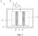
- an anode 42 of a lithium ion capacitor 40 can be pre-doped using a constant voltage charging or constant voltage pre-doping process, not forming a part of this invention.
- Pre-doping a lithium ion capacitor anode 42 using a pre-doing process comprising a constant voltage pre-doping step may facilitate formation of a solid-electrolyte interphase layer having an increased uniformity, stability and/or permeability to lithium ions, thereby providing a lithium ion capacitor having an improved capacitance, a decreased equivalent series resistance and/or an improved cycling performance.
- pre-doping an anode using a constant voltage pre-doping process may facilitate the formation of a pin-hole free or substantially pin-hole free solid-electrolyte interphase layer, thereby providing a lithium ion capacitor having a reduced degree of capacitance fade after a number of charge-discharge cycles.
- a pre-doping process comprising a constant voltage pre-doping step may facilitate a reduced duration of time to achieve a desired level of anode pre-lithiation.
- a pre-doping process which includes applying a short circuit across the anode 42 and the dopant source 46, instantaneously or substantially instantaneously creating a potential difference of about 0V between the anode 42 and the dopant source 46, was found to provide a solid-electrolyte interphase layer having reduced uniformity, stability, and/or permeability to lithium ions, and/or providing a pre-doping process requiring a longer duration to achieve a desired level of anode pre-lithiation.
- a solid-electrolyte interphase layer may form at a potential difference of about 1V.
- Reducing a potential difference between the anode 42 and the dopant source 46 instantaneously or substantially instantaneously to about 0V may provide a less controlled process of pre-doping of the anode 42, for example providing a less controlled process of solid-electrolyte interphase layer formation during the pre-doping process.
- an apparatus for pre-doping a lithium ion capacitor anode 42 can include a dopant source 46 and the anode 42 immersed in an electrolyte 54 (not shown).
- the dopant source 46 can comprise a source of lithium ions.
- the dopant source 46 can comprise a lithium metal.
- the dopant source 46 may be positioned to a side of the anode 42.
- the dopant source 46 may be placed to a side of the anode 42 opposite that facing the capacitor cathode 44.
- the pre-doping apparatus can include a separator 48 between the dopant source 46 and the anode 42.
- the separator 48 may be configured to permit a transport of ionic species (e.g., lithium ions) between the anode 42 and the dopant source 46, while preventing an electrical short between the anode 42 and the dopant source 46.
- the separator 48 can be made of a porous electrically insulating material (e.g., a material comprising a polymer, including a cellulosic material).
- Pre-doping a lithium ion capacitor anode 42 can be performed in-situ. Referring to Figure 2 , pre-doping a lithium ion capacitor 42 can be performed in a lithium ion capacitor cell 40 comprising the anode 42, the dopant source 46, a capacitor cathode 44, and a separator 48 between the anode 42 and cathode 44, and a separator 48 between the anode 42 and the dopant source 46.
- the anode 42, the dopant source 46, the cathode 44, and the separators 48 may be immersed in an electrolyte 54 (not shown).
- the dopant source 46 may be consumed during the constant voltage charging or constant voltage pre-doping step.
- the dopant source 46 may be completely or substantially completely consumed during the constant voltage pre-doping step. At least a portion of the dopant source 46 may remain after the constant voltage pre-doping step, any remaining dopant source 46 being removed upon completion of the pre-doping process. Any remaining dopant source 46 can be removed from a lithium ion capacitor 40 and the lithium ion capacitor 40 can subsequently be sealed. For example, a solid-electrolyte interphase layer formed during an anode pre-doping process comprising a constant voltage pre-doping step can be undisturbed or substantially undisturbed subsequent to its formation. In some embodiments, the remaining dopant source 46 may not be removed until after completion of a formation step performed subsequent to the constant voltage pre-doping step, as described in more detail herein.
- a voltage source 52 can be positioned across the anode 42 and the dopant source 46 (e.g., a lithium metal electrode), the voltage source 52 providing a constant or substantially constant voltage across the anode and the dopant source 46, the dopant source 46.
- the dopant source 46 may be coupled to a first electrode of a voltage source 52, such as a positive electrode of the voltage source 52
- the anode 42 may be coupled to a second electrode of the voltage source 52, such as a negative electrode of the voltage source 52, such that the voltage source 52 can maintain a desired potential difference between the dopant source 46 and the anode 42.
- a constant or substantially constant voltage can be applied across the anode 42 and the dopant source 46 for a duration of time to achieve a desired level of anode pre-lithiation.
- dopants at the dopant source 46 may be released.
- lithium metal at a dopant source 46 comprising a lithium metal electrode may be oxidized. Oxidation of the lithium metal may facilitate a release of lithium ions, thereby providing lithium ions for incorporation into the anode 42.
- a characteristic or a parameter of an anode pre-doping process may affect a characteristic of a solid-electrolyte interphase layer formed adjacent an anode surface during the anode pre-doping process.
- a formation of a solid-electrolyte interphase layer adjacent the anode 42 can depend at least in part on a voltage applied across the anode 42 and the dopant source 46, a duration in which the voltage is applied across the anode 42 and the dopant source 46, and/or a desired level of dopant incorporation into the anode 42.
- a voltage value which is applied across the anode 42 and the dopant source 46 during an anode pre-doping process, a level of dopant incorporation into the anode 42 during the pre-doping process, and/or a duration for which the voltage value is applied across the anode 42 and the dopant source 46 may affect a thickness, a uniformity, a stability and/or a permeability of a solid-electrolyte interphase layer which can form adjacent an anode surface during the anode pre-doping process.
- a voltage applied across the anode 42 and the dopant source 46 during a pre-doping process, a duration for which the voltage is applied across the anode 42 and the dopant source 46, and/or a level of anode pre-lithiation may be determined based at least in part on a desired lithium ion capacitor performance. For example, an applied voltage, a duration in which the voltage is applied, and/or a level of anode pre-lithiation may be selected based at least in part on a desired lithium ion capacitor equivalent series resistance performance, a capacitor capacitance performance, and/or a capacitor cycling performance.
- a cycling performance of the lithium ion capacitor may comprise a degree of capacitance fade exhibited by the capacitor after a number of charge-discharge cycles.
- a voltage applied across the anode 42 and the dopant source 46 and a duration in which the voltage is applied may be selected based at least in part on a desired level of anode pre-lithiation, the level of pre-lithiation corresponding to a formation of a solid-electrolyte interphase layer adjacent a surface of the anode having desirable characteristics, thereby providing a lithium ion capacitor having an improved performance (e.g., a reduced equivalent series resistance, and/or improved cycling performance).
- a constant voltage pre-doping process includes applying a voltage of about 0.001 volts (V) to about 0.400 volts (V), including from about 0.01V to about 0.2V,across an anode 42 and a dopant source 46.
- V 0.001 volts
- V 0.400 volts
- a voltage of about 0.01V to about 0.4V may be applied across the anode 42 and the dopant source 46.
- a voltage of about 0.1V may be applied across the anode 42 and the dopant source 46.
- a formation step can be performed subsequent to a constant voltage pre-doping step.
- a formation step may facilitate improvement and/or stabilization in a characteristic of a solid-electrolyte interphase layer formed during the pre-doping step.
- the formation step can facilitate stabilization of a structural, thermal and/or chemical characteristic of the solid-electrolyte interphase layer, further improving a solid-electrolyte interphase layer uniformity, integrity and/or permeability to lithium ions.
- the formation step can include application of a constant voltage across the anode 42 and the dopant source 46 for a period of time.
- a formation step voltage of about 2 Volts (V) to about 5 V can be applied between the anode 42 and the dopant source 46 in the formation step.
- a formation step voltage can be from about 2 V to about 4.5 V, including about 3V to about 4V, including from about 3.5V to about 4V.
- the formation step voltage can be about 2 V to about 4.2 V.
- the formation step voltage can be applied for a duration of about 5 hours to about 75 hours, including from about 10 hours to about 50 hours.
- a formation step voltage of about of about 3.5V to about 4V can be applied across the anode 42 and the dopant source 46 for about 10 hours to about 50 hours.
- the dopant source 46 may be consumed during the formation step.
- the dopant source 46 may be completely or substantially completely consumed during the formation step. Any remaining dopant source 46 can be removed upon completion of the formation step. Any remaining dopant source 46 can be removed from the lithium ion capacitor 40 and the lithium ion capacitor 40 can be subsequently sealed.
- the solid-electrolyte interphase layer present during the anode pre-doping process and/or during the formation step may advantageously be the same solid-electrolyte interphase layer through which lithium ions are transported in a subsequent charge and/or discharge of the lithium ion capacitor, the solid-electrolyte interphase layer being undisturbed or substantially undisturbed subsequent to its formation.
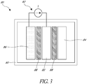
- an anode 82 of a lithium ion capacitor 80 is pre-doped using a process comprising a constant current pre-doping step. Pre-doping a lithium ion capacitor anode using a constant current pre-doping step was found to facilitate formation of a solid-electrolyte interphase layer having an increased uniformity, stability and/or permeability of lithium ions.
- pre-doping an anode using a constant current pre-doping step facilitated the formation of a solid-electrolyte interphase layer having improved structural, thermal and/or chemical stability, and/or a solid-electrolyte interphase free or substantially free of pin-hole defects, thereby providing a lithium ion capacitor having a reduced degree of capacitance fade after a number of charge-discharge cycles.
- a pre-doping process comprising a constant current pre-doping step may reduce a duration of time needed to achieve a desired level of anode pre-lithiation.
- pre-doping a lithium ion capacitor anode 82 using a process comprising a constant current pre-doping step can be performed in a lithium ion capacitor cell 80 (e.g., performed in-situ), the lithium ion capacitor 80 comprising the anode 82, a cathode 84, and a separator 88 between the anode 82 and cathode 84.
- the lithium ion capacitor 80 includes a dopant source 86.
- the dopant source 86 comprises a source of lithium ions.
- the dopant source 86 can comprise a lithium metal (e.g., a lithium metal electrode).
- the dopant source 86 may be positioned to a side of the anode 82.
- the dopant source 86 may be positioned to a side of the anode 82 opposite the side facing the cathode 84.
- the lithium ion capacitor 80 can include a separator 88 between the dopant source 86 and the anode 82.
- the separators 88 may be configured to prevent an electrical short between the anode 82 and the dopant source 86 or the cathode 84, while being permeable to one or more ionic species (e.g., lithium ions).
- the separator 88 can be made of a porous electrically insulating material (e.g., a material comprising a polymer, including a cellulosic material).
- the anode 82, the cathode 84, the dopant source 86, and the separators 88 may be immersed in an electrolyte 94 (not shown).
- the dopant source 86 may be consumed during the constant current charging or pre-doping step. In some embodiments, the dopant source 86 may be completely or substantially completely consumed during the constant current pre-doping step. In some embodiments, at least a portion of the dopant source 86 remains after the constant current pre-doping step and the remaining portion of the dopant source 86 can be removed upon completion of the pre-doping process. In some embodiments, any remaining dopant source 86 can be removed from a lithium ion capacitor 80 and the lithium ion capacitor 80 can be subsequently sealed.
- a solid-electrolyte interphase layer formed during an anode pre-doping process comprising a constant current pre-doping step can be undisturbed or substantially undisturbed subsequent to its formation.
- the dopant source 86 may not be removed until after completion of a formation step performed subsequent to the constant current pre-doping step, as described in more detail herein.
- a current source 92 providing a constant or substantially constant current flow can be positioned across an anode 82 and a dopant source 86 (e.g., a lithium metal electrode).
- the dopant source 86 may be coupled to a first electrode of a current source 92 and the anode 82 may be coupled to a second electrode of the current source 92 such that the current source 92 can maintain a desired current flow between the dopant source 86 and the anode 82.
- a current corresponding to a current C-rate of about C/72 to about C/144 (e.g., a current C-rate of about C/72 corresponds to a current such that the capacitor can be completely or substantially completely discharged in about 72 hours, and a current C-rate of about C/144 corresponds to a current such that the capacitor can be completely or substantially completely discharged in about 144 hours), including from about C/72 to about C/96, may be maintained between the anode 82 and the dopant source 86.
- the current source 92 can provide a current corresponding to a current C-rate of about C/72 to about C/144.
- a current corresponding to a current C-rate of about C/72 may be maintained between the anode 82 and the dopant source 86.
- a constant or substantially constant current flow is maintained between the anode 82 and the dopant source 86 for a duration of time. For example, a current flow may be maintained until a desired potential difference between the anode 82 and the dopant source 86 is achieved. In some embodiments, a potential difference between an anode 86 and a dopant source 86 may be reduced from a value at about an open circuit voltage value to a desired voltage value.
- a current flow of a constant or substantially constant value may be maintained between the anode 82 and the dopant source 86 such that a potential difference between the anode 82 and the dopant source 86 may be reduced from about an open circuit voltage (OCV) (e.g., about 3V) to a desired potential difference.
- OCV open circuit voltage
- an anode pre-doping process comprising maintaining a constant current flow between an anode 82 and a dopant source 86 can provide a method of controlled anode pre-lithiation.
- a constant or substantially constant current is maintained until a potential difference of about 0.01V to 0.4V, including about 0.01V to about 0.2V is achieved across the anode 82 and the dopant source 86.
- a constant or substantially constant current can be maintained until a potential difference of about 0.1V is achieved across the anode 82 and the dopant source 86.
- an anode pre-doping process comprising a constant current charging step can provide increased control of an anode pre-lithiation level, and/or an improved control over formation of a solid-electrolyte interphase layer adjacent the anode.
- a characteristic of a solid-electrolyte interphase layer formed adjacent the anode 82 during a pre-doping process can depend at least in part on a characteristic or parameter of the pre-doping process, including but not limited to a current flow maintained between the anode 82 and the dopant source 86, a duration in which the current flow is maintained, and/or a desired level of dopant incorporation into the anode 82.
- a current value which is maintained between the anode 82 and the dopant source 86 during an anode pre-doping process, a level of dopant incorporation into the anode 82 during the pre-doping process, and/or a duration for which the current value which is maintained between the anode 82 and the dopant source 86 may affect a thickness, a uniformity, a stability and/or a permeability of a solid-electrolyte interphase layer which can form adjacent an anode surface during the anode pre-doping process.
- a current maintained between the anode 82 and the dopant source 86 during a pre-doping process, a duration for which the current is maintained between the anode 82 and the dopant source 86, and/or a level of anode pre-lithiation may be determined based at least in part on a desired lithium ion capacitor performance.
- a current flow, a duration in which the current is maintained, and/or a level of anode pre-lithiation may be selected based at least in part on a desired lithium ion capacitor equivalent series resistance performance, a capacitance performance, and/or a cycling performance (e.g., a degree of capacitance fade exhibited by the capacitor after a number of charge-discharge cycles).
- current maintained between the anode 82 and the dopant source 86, and a duration in which the current is maintained may be selected based at least in part on a desired level of anode pre-lithiation, the level of pre-lithiation corresponding to a formation of a solid-electrolyte interphase layer adjacent a surface of the anode having desirable characteristics, thereby providing a lithium ion capacitor having an improved performance (e.g., a reduced equivalent series resistance, and/or improved cycling performance).
- a formation step can be performed subsequent to a constant current pre-doping step.
- a formation step may facilitate improvement and/or stabilization in a characteristic of a solid-electrolyte interphase layer formed during the constant current pre-doping step.
- the formation step performed subsequent to the constant current pre-doping step can facilitate stabilization of a structural, thermal and/or chemical characteristic of the solid-electrolyte interphase layer, further improving a solid-electrolyte interphase layer uniformity, integrity and/or permeability to lithium ions.
- this formation step can include application of a constant voltage across the anode 82 and the dopant source 86 for a period of time.
- a formation step voltage of about 2 Volts (V) to about 5 V can be applied between the anode 82 and the dopant source 86 in the formation step.
- a formation step voltage can be from about 2 V to about 4.5 V, including about 3V to about 4V, including from about 3.5V to about 4V.
- the formation step voltage can be about 2 V to about 4.2 V.
- the formation step voltage can be applied for a duration of about 5 hours to about 75 hours, including from about 10 hours to about 50 hours.
- a formation step voltage of about of about 3.5V to about 4V can be applied across the anode 82 and the dopant source 86 for about 10 hours to about 50 hours.
- the dopant source 86 may be consumed during the formation step, including being completely or substantially completely consumed. In some embodiments, at least a portion of the dopant source 86 remains upon completion of the formation step, and the remaining dopant source 86 can be removed from the lithium ion capacitor 80 and the lithium ion capacitor 80 can be subsequently sealed.
- the solid-electrolyte interphase layer present during the constant current anode pre-doping process and/or during the formation step may advantageously be the same solid-electrolyte interphase layer through which lithium ions are transported in a subsequent capacitor charge and/or discharge, the solid-electrolyte interphase layer being undisturbed or substantially undisturbed subsequent to its formation.
- a current of a constant current pre-doping step, and/or a duration of a pre-doping step can be selected to achieve a desired level of lithium ion pre-doping in a capacitor anode.
- a level of lithium ion pre-doping can be selected to facilitate improved capacitor capacitance, resistance and/or cycling performance.
- the current of a constant-current pre-doping process, and/or the duration of the pre-doping process are selected to facilitate achieving a lithium ion pre-doping level of about 60% to about 90%, including about 60% to about 65%.
- Figures 4 through 8 show capacitance, resistance and/or cycling performances of one or more lithium ion capacitors pre-doped using one or more of the constant voltage pre-doping or constant current pre-doping processes described herein.
- Components of the one or more capacitors can have one or more compositions as described herein.
- Figure 4 shows measured capacity performances of example anodes of lithium ion capacitors pre-doped using a pre-doping process comprising a constant voltage pre-doping process, which is not a part of this invention.
- Lithium ion capacitors were subject to a pre-doping process comprising a constant voltage pre-doping step (e.g., a pre-doping process including an example capacitor 40 as shown in Figure 2 ), and the capacity of the lithium ion capacitors was subsequently measured.
- Figure 4 shows an increase in a measured capacity, in milliampere-hour (mAh), when a decreased voltage is applied during a constant voltage pre-doping process.
- mAh milliampere-hour
- a lithium ion capacitor having an anode pre-doped using a constant voltage pre-doping step at a constant voltage of about 0.1V can have an anode capacity measurement (e.g., at about 18 mAh, larger than that of a lithium ion capacitor having an anode pre-doped using a constant voltage of about 0.2V (e.g., at about 14 mAh).
- Figure 4 also shows a level of anode lithium ion pre-doping and corresponding voltage maintained during the constant voltage pre-doping step.
- a level of lithium ion pre-doping e.g., a level of lithium ion incorporation, a level of pre-lithiation
- a level of lithium ion pre-doping into an anode can be proportional to a constant voltage value applied during a pre-doping process, the level of lithium ion incorporation decreasing with an increasing constant voltage value.
- a level of lithium ion pre-doping in an anode pre-doped using a constant voltage of about 0.4 Volts (V) can have a lower lithium ion pre-doping level than that of an anode pre-doped using a constant voltage of about 0.1V.
- a voltage applied in a constant voltage pre-doping step may be selected based on a desired level of anode lithium ion pre-pre-doping.
- Figure 5 includes a table showing example measured lithium ion capacitor performance parameters of capacitors corresponding to some of the capacitor anodes shown in Figure 4 .
- Figure 5 shows measured lithium ion capacitor performance parameters corresponding to voltage values (e.g., "Pre-lithiation Voltage") applied during a constant voltage pre-doping process.
- a corresponding percentage of anode pre-lithiation e.g., "% predoping”
- a capacitance value measured in Farads F
- Capacitance, F an equivalent series resistance measured in Ohms
- ⁇ equivalent series resistance measured in Ohms
- ESR, Ohms ESR, Ohms
- an RC time constant calculated from the measured capacitance value and the measured resistance of the lithium ion capacitor are listed.
- the lithium ion capacitor having an anode which was pre-doped using a constant voltage of about 0.1 V in a constant voltage pre-doping step exhibited the lowest RC time constant, and/or measured equivalent series resistance.
- the anode of the capacitor having the lowest RC time constant was pre-doped to a lithium ion pre-doping level of about 60%.
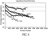
- Figure 6 shows cycling performance of some of the lithium ion capacitors of Figure 4 .
- a capacitance of the lithium ion capacitors was measured after cycling a number of cycles between a voltage of about 2.2 Volts (V) and 4.2 V, at a current C-rate of about 30C (e.g., a current C-rate of about 30C can correspond to a current such that the capacitor can be completely or substantially completely discharged in about 1/30 of an hour), in ambient conditions, to measure a percentage of reduction in measured capacitance as compared to an initial capacitance of the lithium ion capacitor prior to cycling (e.g., a capacitance fade performance).
- Figure 6 shows a general improvement in the cycling performance as voltage applied during a constant voltage pre-doping step decreases.
- the lithium ion capacitor having an anode which was pre-doped using a constant voltage of about 0.1V in a constant voltage pre-doping step show a reduced degree of capacitance fade after a number of charge-discharge cycles, for example as compared to that of a capacitor having an anode pre-doped using a constant voltage of about 0.4V.
- a lithium ion capacitor exhibiting a reduced degree of capacitance fade, a reduced equivalent series resistance and/or a reduced RC time constant may have a solid-electrolyte interphase layer having a decreased thickness, an increased uniformity, an improved stability and/or an increased permeability of lithium ions.
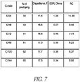
- Figure 7 includes a table showing example measured lithium ion capacitor performance parameters corresponding to current flow rates (e.g., "C-rate") maintained during a constant current pre-doping step of an anode pre-doping process, according to the invention.
- current maintained during a constant current pre-doping step is expressed as a rate at which the capacitor can be discharged and/or charged, a larger C-rate corresponding to a higher current.
- a current corresponding to a C-rate of about C/48 is greater than a current corresponding to a C-rate of about C/96.
- a corresponding level to which lithium ions were incorporated into an anode of the lithium ion capacitor e.g., "% pre-doping”
- a capacitance value measured in Farads (F) e.g.., “Capacitance, F”
- an equivalent series resistance measured in Ohms e.g., "ESR, Ohms”
- an RC time constant calculated from the capacitance value and the resistance of the lithium ion capacitor are listed.
- decreasing a constant current flow rate maintained between an anode and a dopant source can reduce an equivalent series resistance, and/or RC time constant, of the lithium ion capacitor.
- capacitors having anodes pre-doped at reduced currents can demonstrate a reduced equivalent series resistance (ESR) and/or RC time constant.
- ESR reduced equivalent series resistance
- a decreased current maintained during a constant current pre-doping step can facilitate increased lithium ion pre-doping level.
- an anode pre-doped to a level of about 60% to about 65% can demonstrate a reduced equivalent series resistance (ESR) and/or RC time constant.
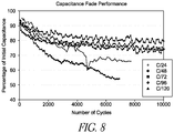
- Figure 8 shows cycling performance of some of the lithium ion capacitors of Figure 7 .
- a capacitance of the lithium ion capacitors was measured after cycling a number of cycles between a voltage of about 2.2 Volts (V) and 4.2 V, at a current C-rate of about 30C (e.g., a current C-rate of about 30C can correspond to a current such that the capacitor can be completely or substantially completely discharged in about 1/30 of an hour), in ambient conditions to measure a percentage of reduction in measured capacitance as compared to an initial capacitance of the lithium ion capacitor prior to cycling (e.g., a capacitance fade performance).
- Figure 8 shows a general improvement in the cycling performance as current maintained during a constant current step decreases.
- the lithium ion capacitor having an anode which was pre-doped using a constant current charging step having a current C-rate of about C/96, as shown in Figure 8 shows a reduced degree of capacitance fade after a number of charge-discharge cycles.
- a lithium ion capacitor exhibiting a reduced degree of capacitance fade a reduced equivalent series resistance, and/or a reduced RC time constant may have a solid-electrolyte interphase layer having a decreased thickness, an increased uniformity, an improved stability and/or an increased permeability of lithium ions.
- An anode pre-doping process comprising a constant current pre-doping step may provide an increased control over a degree of anode pre-lithiation.
- a current maintained in a constant current pre-doping step can be selected based on a desired anode lithium ion pre-doping level.
- An improved control in a level to which lithium ions are incorporated into a lithium ion capacitor anode may provide an improved control in a formation of a solid-electrolyte interphase layer, facilitating for example an improved lithium ion capacitor performance.
- an anode pre-doping process comprising a constant current pre-doping step can facilitate formation of a solid-electrolyte interphase layer having an improved stability, uniformity, and/or permeability of lithium ions.
- An anode pre-doping process comprising a constant current pre-doping step may provide a lithium ion capacitor exhibiting a reduced equivalent series resistance performance, a reduced RC time constant, and/or a reduced degree of capacitance fade after a number charge-discharge cycles.
Landscapes
- Engineering & Computer Science (AREA)
- Power Engineering (AREA)
- Chemical & Material Sciences (AREA)
- Materials Engineering (AREA)
- Microelectronics & Electronic Packaging (AREA)
- Electric Double-Layer Capacitors Or The Like (AREA)
- Chemical Kinetics & Catalysis (AREA)
- Electrochemistry (AREA)
- General Chemical & Material Sciences (AREA)
- Manufacturing & Machinery (AREA)
- Battery Electrode And Active Subsutance (AREA)
- Secondary Cells (AREA)
- Inorganic Chemistry (AREA)
Applications Claiming Priority (2)
| Application Number | Priority Date | Filing Date | Title |
|---|---|---|---|
| US201361815157P | 2013-04-23 | 2013-04-23 | |
| PCT/US2014/035012 WO2014176267A1 (en) | 2013-04-23 | 2014-04-22 | Methods for solid electrolyte interphase formation and anode pre-lithiation of lithium ion capacitors |
Publications (2)
| Publication Number | Publication Date |
|---|---|
| EP2989649A1 EP2989649A1 (en) | 2016-03-02 |
| EP2989649B1 true EP2989649B1 (en) | 2019-04-03 |
Family
ID=50842342
Family Applications (1)
| Application Number | Title | Priority Date | Filing Date |
|---|---|---|---|
| EP14727297.5A Active EP2989649B1 (en) | 2013-04-23 | 2014-04-22 | Methods for solid electrolyte interphase formation and anode pre-lithiation of lithium ion capacitors |
Country Status (7)
| Country | Link |
|---|---|
| US (1) | US9711297B2 (ko) |
| EP (1) | EP2989649B1 (ko) |
| JP (1) | JP6181855B2 (ko) |
| KR (1) | KR102380895B1 (ko) |
| CN (1) | CN105164776B (ko) |
| HK (1) | HK1218989A1 (ko) |
| WO (1) | WO2014176267A1 (ko) |
Families Citing this family (16)
| Publication number | Priority date | Publication date | Assignee | Title |
|---|---|---|---|---|
| US9779885B2 (en) | 2012-11-09 | 2017-10-03 | Corning Incorporated | Method of pre-doping a lithium ion capacitor |
| US10497935B2 (en) * | 2014-11-03 | 2019-12-03 | 24M Technologies, Inc. | Pre-lithiation of electrode materials in a semi-solid electrode |
| CN104701031B (zh) * | 2014-12-12 | 2018-01-09 | 宁波中车新能源科技有限公司 | 一种锂离子电容器的制作方法及锂离子电容器 |
| EP3420607A1 (en) | 2016-02-23 | 2019-01-02 | Maxwell Technologies, Inc. | Elemental metal and carbon mixtures for energy storage devices |
| CN113921287B (zh) | 2016-02-26 | 2023-06-13 | 武藏能源解决方案有限公司 | 掺杂系统、以及电极、电池和电容器的制造方法 |
| US20170256782A1 (en) * | 2016-03-01 | 2017-09-07 | Maxwell Technologies, Inc. | Pre-doped anodes and methods and apparatuses for making same |
| CN110537269B (zh) * | 2017-02-21 | 2023-07-07 | 特斯拉公司 | 预锂化储能装置 |
| DE102017206969A1 (de) | 2017-04-26 | 2018-10-31 | Robert Bosch Gmbh | Verfahren zur Herstellung eines Elektrodenfilms und Elektrode |
| CN111033658A (zh) * | 2017-06-14 | 2020-04-17 | Ioxus公司 | 用于制备电化学储能装置的固体电解质界面的系统和方法 |
| EP3769357A1 (en) | 2018-03-22 | 2021-01-27 | FMC Lithium USA Corp. | Methods of applying printable lithium compositions for forming battery electrodes |
| US11264598B2 (en) | 2018-03-22 | 2022-03-01 | Fmc Lithium Usa Corp. | Battery utilizing printable lithium |
| US11735764B2 (en) | 2018-03-22 | 2023-08-22 | Livent USA Corp. | Printable lithium compositions |
| CN109698323B (zh) * | 2018-11-30 | 2022-03-22 | 江苏天合储能有限公司 | 一种用于锂离子电池的预锂化负极材料及其制备方法 |
| SG11202108854XA (en) | 2019-03-20 | 2021-09-29 | Fmc Lithium Usa Corp | Printed lithium foil and film |
| WO2020226354A1 (ko) * | 2019-05-03 | 2020-11-12 | 주식회사 엘지화학 | 이차전지용 양극의 제조방법, 이와 같이 제조된 양극 및 이를 포함하는 리튬 이차전지 |
| JP2023529515A (ja) | 2020-02-19 | 2023-07-11 | リベント ユーエスエー コーポレイション | 急速充電プレリチウム化シリコンアノード |
Citations (1)
| Publication number | Priority date | Publication date | Assignee | Title |
|---|---|---|---|---|
| US5743921A (en) * | 1995-07-03 | 1998-04-28 | General Motors Corporation | Method of making a cell using a lithium-deactivated carbon anode |
Family Cites Families (20)
| Publication number | Priority date | Publication date | Assignee | Title |
|---|---|---|---|---|
| US4442187A (en) * | 1980-03-11 | 1984-04-10 | University Patents, Inc. | Batteries having conjugated polymer electrodes |
| US4728589A (en) * | 1980-03-11 | 1988-03-01 | University Patents, Inc. | Reversible electrochemical doping of conjugated polymers and secondary batteries based thereon |
| US4801512A (en) * | 1980-03-11 | 1989-01-31 | University Patents, Inc. | Reversible electrochemical doping of conjugated polymers and secondary batteries based thereon |
| EP0058469B1 (en) * | 1981-01-22 | 1987-07-22 | Showa Denko Kabushiki Kaisha | Battery having acetylene high polymer electrode |
| US5759715A (en) | 1995-09-26 | 1998-06-02 | Valence Technology, Inc. | Lithium ion batteries containing pre-lithiated electrodes |
| JP4765109B2 (ja) * | 2005-03-15 | 2011-09-07 | Tdk株式会社 | 電極用炭素材料及びその製造方法、電極及びその製造方法、並びに、電気化学デバイス及びその製造方法 |
| JP4779985B2 (ja) * | 2007-02-07 | 2011-09-28 | トヨタ自動車株式会社 | 予備ドープ前リチウムイオン電池、およびリチウムイオン電池の製造方法 |
| JP2010532071A (ja) * | 2007-06-29 | 2010-09-30 | コモンウェルス サイエンティフィック アンド インダストリアル リサーチ オーガニゼイション | リチウムエネルギー蓄積デバイス |
| CN102301439B (zh) | 2008-12-26 | 2014-03-12 | Jm能源股份有限公司 | 卷绕型蓄电池 |
| JP5372568B2 (ja) * | 2009-03-27 | 2013-12-18 | 富士重工業株式会社 | 蓄電デバイスおよびその製造方法 |
| JP2013527628A (ja) * | 2010-06-02 | 2013-06-27 | フロリダ・ステイト・ユニバーシティ・リサーチ・ファウンデイション・インコーポレイテッド | 高エネルギー密度電気化学キャパシタ |
| KR101101546B1 (ko) | 2010-06-21 | 2012-01-02 | 삼성전기주식회사 | 전기 화학 커패시터 및 이의 제조방법 |
| KR101128654B1 (ko) * | 2010-08-19 | 2012-03-26 | 삼성전기주식회사 | 전극의 리튬 이온 프리 도핑 방법 및 이를 이용한 전기 화학 커패시터의 제조 방법 |
| JP2012212629A (ja) * | 2011-03-31 | 2012-11-01 | Fuji Heavy Ind Ltd | リチウムイオン蓄電デバイスの製造方法 |
| US20120262845A1 (en) * | 2011-04-14 | 2012-10-18 | Samsung Electro-Mechanics Co., Ltd. | Magnesium capacitor and method for preparing the same |
| US20120300366A1 (en) | 2011-05-27 | 2012-11-29 | Samsung Electro-Mechanics Co., Ltd. | Method for pre-doping anode and lithium ion capacitor storage device including the same |
| KR101179629B1 (ko) * | 2011-07-07 | 2012-09-10 | 한국에너지기술연구원 | 리튬 이온의 프리 도핑 방법에 따른 리튬 이온 커패시터 제조 방법 및 이의 리튬 이온 커패시터 |
| US9385397B2 (en) * | 2011-08-19 | 2016-07-05 | Nanotek Instruments, Inc. | Prelithiated current collector and secondary lithium cells containing same |
| KR102004561B1 (ko) * | 2011-10-18 | 2019-07-26 | 제이에스알 가부시끼가이샤 | 보호막 및 그것을 제조하기 위한 조성물, 슬러리, 및 축전 디바이스 |
| CN103050295B (zh) * | 2012-12-20 | 2016-03-23 | 上海奥威科技开发有限公司 | 一种锂离子电容器 |
-
2014
- 2014-04-22 JP JP2016510742A patent/JP6181855B2/ja active Active
- 2014-04-22 KR KR1020157033260A patent/KR102380895B1/ko active IP Right Grant
- 2014-04-22 US US14/258,784 patent/US9711297B2/en active Active
- 2014-04-22 CN CN201480023057.1A patent/CN105164776B/zh active Active
- 2014-04-22 WO PCT/US2014/035012 patent/WO2014176267A1/en active Application Filing
- 2014-04-22 EP EP14727297.5A patent/EP2989649B1/en active Active
-
2016
- 2016-06-16 HK HK16106948.2A patent/HK1218989A1/zh unknown
Patent Citations (1)
| Publication number | Priority date | Publication date | Assignee | Title |
|---|---|---|---|---|
| US5743921A (en) * | 1995-07-03 | 1998-04-28 | General Motors Corporation | Method of making a cell using a lithium-deactivated carbon anode |
Also Published As
| Publication number | Publication date |
|---|---|
| KR102380895B1 (ko) | 2022-03-31 |
| WO2014176267A1 (en) | 2014-10-30 |
| JP2016521007A (ja) | 2016-07-14 |
| CN105164776A (zh) | 2015-12-16 |
| JP6181855B2 (ja) | 2017-08-16 |
| EP2989649A1 (en) | 2016-03-02 |
| US20140313639A1 (en) | 2014-10-23 |
| HK1218989A1 (zh) | 2017-03-17 |
| US9711297B2 (en) | 2017-07-18 |
| CN105164776B (zh) | 2019-03-08 |
| KR20160003017A (ko) | 2016-01-08 |
Similar Documents
| Publication | Publication Date | Title |
|---|---|---|
| EP2989649B1 (en) | Methods for solid electrolyte interphase formation and anode pre-lithiation of lithium ion capacitors | |
| US10707027B2 (en) | Formulations for and methods of fabricating energy storage device electrodes | |
| JP4857073B2 (ja) | リチウムイオンキャパシタ | |
| Decaux et al. | Electrochemical performance of a hybrid lithium-ion capacitor with a graphite anode preloaded from lithium bis (trifluoromethane) sulfonimide-based electrolyte | |
| US9245691B1 (en) | High energy density electrochemical capacitors | |
| KR101516500B1 (ko) | 전기 화학 디바이스 | |
| KR102655905B1 (ko) | 프리-도핑된 애노드들 및 그의 제조를 위한 방법들 및 장치들 | |
| JP2008252013A (ja) | リチウムイオンキャパシタ | |
| JP2012089825A (ja) | リチウムイオンキャパシタ | |
| JP2012004491A (ja) | 蓄電デバイス | |
| US20140315084A1 (en) | Method and apparatus for energy storage | |
| JP4863001B2 (ja) | 蓄電デバイスおよびその製造方法 | |
| KR102379507B1 (ko) | 포스포린 기반 음극을 갖는 고밀도 하이브리드 슈퍼커패시터 및 그 제조 방법 | |
| JP4863000B2 (ja) | 蓄電デバイスおよびその製造方法 | |
| CN116420209A (zh) | 电化学器件 | |
| KR20220049723A (ko) | 질소 및 불소가 공동 도핑된 슈퍼커패시터용 전극활물질 제조 방법과, 이를 이용한 고출력 슈퍼커패시터 및 그 제조 방법 | |
| US20190295783A1 (en) | Electrolyte liquid for electrochemical device and electrochemical device | |
| JP2012114201A (ja) | 蓄電デバイス | |
| Akhtar et al. | Hybrid Supercapacitor-Battery Energy Storage | |
| JP2018148018A (ja) | 非水系蓄電素子 | |
| JP2014127656A (ja) | 非水電解液蓄電素子 |
Legal Events
| Date | Code | Title | Description |
|---|---|---|---|
| PUAI | Public reference made under article 153(3) epc to a published international application that has entered the european phase |
Free format text: ORIGINAL CODE: 0009012 |
|
| 17P | Request for examination filed |
Effective date: 20151120 |
|
| AK | Designated contracting states |
Kind code of ref document: A1 Designated state(s): AL AT BE BG CH CY CZ DE DK EE ES FI FR GB GR HR HU IE IS IT LI LT LU LV MC MK MT NL NO PL PT RO RS SE SI SK SM TR |
|
| AX | Request for extension of the european patent |
Extension state: BA ME |
|
| DAX | Request for extension of the european patent (deleted) | ||
| STAA | Information on the status of an ep patent application or granted ep patent |
Free format text: STATUS: EXAMINATION IS IN PROGRESS |
|
| 17Q | First examination report despatched |
Effective date: 20170203 |
|
| GRAP | Despatch of communication of intention to grant a patent |
Free format text: ORIGINAL CODE: EPIDOSNIGR1 |
|
| STAA | Information on the status of an ep patent application or granted ep patent |
Free format text: STATUS: GRANT OF PATENT IS INTENDED |
|
| RIC1 | Information provided on ipc code assigned before grant |
Ipc: H01M 6/50 20060101ALN20181001BHEP Ipc: H01G 11/06 20130101AFI20181001BHEP Ipc: H01M 4/133 20100101ALN20181001BHEP Ipc: H01M 4/1393 20100101ALN20181001BHEP Ipc: H01G 11/50 20130101ALI20181001BHEP Ipc: H01G 11/86 20130101ALN20181001BHEP Ipc: H01M 4/04 20060101ALN20181001BHEP Ipc: H01M 4/587 20100101ALN20181001BHEP |
|
| RIC1 | Information provided on ipc code assigned before grant |
Ipc: H01M 6/50 20060101ALN20181005BHEP Ipc: H01M 4/04 20060101ALN20181005BHEP Ipc: H01G 11/86 20130101ALN20181005BHEP Ipc: H01G 11/50 20130101ALI20181005BHEP Ipc: H01M 4/1393 20100101ALN20181005BHEP Ipc: H01M 4/587 20100101ALN20181005BHEP Ipc: H01M 4/133 20100101ALN20181005BHEP Ipc: H01G 11/06 20130101AFI20181005BHEP |
|
| INTG | Intention to grant announced |
Effective date: 20181024 |
|
| GRAS | Grant fee paid |
Free format text: ORIGINAL CODE: EPIDOSNIGR3 |
|
| GRAA | (expected) grant |
Free format text: ORIGINAL CODE: 0009210 |
|
| STAA | Information on the status of an ep patent application or granted ep patent |
Free format text: STATUS: THE PATENT HAS BEEN GRANTED |
|
| AK | Designated contracting states |
Kind code of ref document: B1 Designated state(s): AL AT BE BG CH CY CZ DE DK EE ES FI FR GB GR HR HU IE IS IT LI LT LU LV MC MK MT NL NO PL PT RO RS SE SI SK SM TR |
|
| REG | Reference to a national code |
Ref country code: GB Ref legal event code: FG4D |
|
| REG | Reference to a national code |
Ref country code: CH Ref legal event code: EP Ref country code: AT Ref legal event code: REF Ref document number: 1116744 Country of ref document: AT Kind code of ref document: T Effective date: 20190415 |
|
| REG | Reference to a national code |
Ref country code: DE Ref legal event code: R096 Ref document number: 602014043989 Country of ref document: DE |
|
| REG | Reference to a national code |
Ref country code: IE Ref legal event code: FG4D |
|
| REG | Reference to a national code |
Ref country code: NL Ref legal event code: MP Effective date: 20190403 |
|
| REG | Reference to a national code |
Ref country code: LT Ref legal event code: MG4D |
|
| REG | Reference to a national code |
Ref country code: AT Ref legal event code: MK05 Ref document number: 1116744 Country of ref document: AT Kind code of ref document: T Effective date: 20190403 |
|
| PG25 | Lapsed in a contracting state [announced via postgrant information from national office to epo] |
Ref country code: NL Free format text: LAPSE BECAUSE OF FAILURE TO SUBMIT A TRANSLATION OF THE DESCRIPTION OR TO PAY THE FEE WITHIN THE PRESCRIBED TIME-LIMIT Effective date: 20190403 |
|
| PG25 | Lapsed in a contracting state [announced via postgrant information from national office to epo] |
Ref country code: CZ Free format text: LAPSE BECAUSE OF FAILURE TO SUBMIT A TRANSLATION OF THE DESCRIPTION OR TO PAY THE FEE WITHIN THE PRESCRIBED TIME-LIMIT Effective date: 20190403 Ref country code: AL Free format text: LAPSE BECAUSE OF FAILURE TO SUBMIT A TRANSLATION OF THE DESCRIPTION OR TO PAY THE FEE WITHIN THE PRESCRIBED TIME-LIMIT Effective date: 20190403 Ref country code: PT Free format text: LAPSE BECAUSE OF FAILURE TO SUBMIT A TRANSLATION OF THE DESCRIPTION OR TO PAY THE FEE WITHIN THE PRESCRIBED TIME-LIMIT Effective date: 20190803 Ref country code: FI Free format text: LAPSE BECAUSE OF FAILURE TO SUBMIT A TRANSLATION OF THE DESCRIPTION OR TO PAY THE FEE WITHIN THE PRESCRIBED TIME-LIMIT Effective date: 20190403 Ref country code: LT Free format text: LAPSE BECAUSE OF FAILURE TO SUBMIT A TRANSLATION OF THE DESCRIPTION OR TO PAY THE FEE WITHIN THE PRESCRIBED TIME-LIMIT Effective date: 20190403 Ref country code: HR Free format text: LAPSE BECAUSE OF FAILURE TO SUBMIT A TRANSLATION OF THE DESCRIPTION OR TO PAY THE FEE WITHIN THE PRESCRIBED TIME-LIMIT Effective date: 20190403 Ref country code: SE Free format text: LAPSE BECAUSE OF FAILURE TO SUBMIT A TRANSLATION OF THE DESCRIPTION OR TO PAY THE FEE WITHIN THE PRESCRIBED TIME-LIMIT Effective date: 20190403 Ref country code: NO Free format text: LAPSE BECAUSE OF FAILURE TO SUBMIT A TRANSLATION OF THE DESCRIPTION OR TO PAY THE FEE WITHIN THE PRESCRIBED TIME-LIMIT Effective date: 20190703 Ref country code: ES Free format text: LAPSE BECAUSE OF FAILURE TO SUBMIT A TRANSLATION OF THE DESCRIPTION OR TO PAY THE FEE WITHIN THE PRESCRIBED TIME-LIMIT Effective date: 20190403 |
|
| PG25 | Lapsed in a contracting state [announced via postgrant information from national office to epo] |
Ref country code: LV Free format text: LAPSE BECAUSE OF FAILURE TO SUBMIT A TRANSLATION OF THE DESCRIPTION OR TO PAY THE FEE WITHIN THE PRESCRIBED TIME-LIMIT Effective date: 20190403 Ref country code: RS Free format text: LAPSE BECAUSE OF FAILURE TO SUBMIT A TRANSLATION OF THE DESCRIPTION OR TO PAY THE FEE WITHIN THE PRESCRIBED TIME-LIMIT Effective date: 20190403 Ref country code: PL Free format text: LAPSE BECAUSE OF FAILURE TO SUBMIT A TRANSLATION OF THE DESCRIPTION OR TO PAY THE FEE WITHIN THE PRESCRIBED TIME-LIMIT Effective date: 20190403 Ref country code: BG Free format text: LAPSE BECAUSE OF FAILURE TO SUBMIT A TRANSLATION OF THE DESCRIPTION OR TO PAY THE FEE WITHIN THE PRESCRIBED TIME-LIMIT Effective date: 20190703 Ref country code: GR Free format text: LAPSE BECAUSE OF FAILURE TO SUBMIT A TRANSLATION OF THE DESCRIPTION OR TO PAY THE FEE WITHIN THE PRESCRIBED TIME-LIMIT Effective date: 20190704 |
|
| REG | Reference to a national code |
Ref country code: CH Ref legal event code: PL |
|
| REG | Reference to a national code |
Ref country code: BE Ref legal event code: MM Effective date: 20190430 |
|
| PG25 | Lapsed in a contracting state [announced via postgrant information from national office to epo] |
Ref country code: LU Free format text: LAPSE BECAUSE OF NON-PAYMENT OF DUE FEES Effective date: 20190422 Ref country code: IS Free format text: LAPSE BECAUSE OF FAILURE TO SUBMIT A TRANSLATION OF THE DESCRIPTION OR TO PAY THE FEE WITHIN THE PRESCRIBED TIME-LIMIT Effective date: 20190803 Ref country code: AT Free format text: LAPSE BECAUSE OF FAILURE TO SUBMIT A TRANSLATION OF THE DESCRIPTION OR TO PAY THE FEE WITHIN THE PRESCRIBED TIME-LIMIT Effective date: 20190403 |
|
| REG | Reference to a national code |
Ref country code: DE Ref legal event code: R097 Ref document number: 602014043989 Country of ref document: DE |
|
| PG25 | Lapsed in a contracting state [announced via postgrant information from national office to epo] |
Ref country code: DK Free format text: LAPSE BECAUSE OF FAILURE TO SUBMIT A TRANSLATION OF THE DESCRIPTION OR TO PAY THE FEE WITHIN THE PRESCRIBED TIME-LIMIT Effective date: 20190403 Ref country code: RO Free format text: LAPSE BECAUSE OF FAILURE TO SUBMIT A TRANSLATION OF THE DESCRIPTION OR TO PAY THE FEE WITHIN THE PRESCRIBED TIME-LIMIT Effective date: 20190403 Ref country code: EE Free format text: LAPSE BECAUSE OF FAILURE TO SUBMIT A TRANSLATION OF THE DESCRIPTION OR TO PAY THE FEE WITHIN THE PRESCRIBED TIME-LIMIT Effective date: 20190403 Ref country code: CH Free format text: LAPSE BECAUSE OF NON-PAYMENT OF DUE FEES Effective date: 20190430 Ref country code: LI Free format text: LAPSE BECAUSE OF NON-PAYMENT OF DUE FEES Effective date: 20190430 Ref country code: SK Free format text: LAPSE BECAUSE OF FAILURE TO SUBMIT A TRANSLATION OF THE DESCRIPTION OR TO PAY THE FEE WITHIN THE PRESCRIBED TIME-LIMIT Effective date: 20190403 Ref country code: MC Free format text: LAPSE BECAUSE OF FAILURE TO SUBMIT A TRANSLATION OF THE DESCRIPTION OR TO PAY THE FEE WITHIN THE PRESCRIBED TIME-LIMIT Effective date: 20190403 |
|
| PLBE | No opposition filed within time limit |
Free format text: ORIGINAL CODE: 0009261 |
|
| STAA | Information on the status of an ep patent application or granted ep patent |
Free format text: STATUS: NO OPPOSITION FILED WITHIN TIME LIMIT |
|
| PG25 | Lapsed in a contracting state [announced via postgrant information from national office to epo] |
Ref country code: SM Free format text: LAPSE BECAUSE OF FAILURE TO SUBMIT A TRANSLATION OF THE DESCRIPTION OR TO PAY THE FEE WITHIN THE PRESCRIBED TIME-LIMIT Effective date: 20190403 Ref country code: BE Free format text: LAPSE BECAUSE OF NON-PAYMENT OF DUE FEES Effective date: 20190430 |
|
| 26N | No opposition filed |
Effective date: 20200106 |
|
| PG25 | Lapsed in a contracting state [announced via postgrant information from national office to epo] |
Ref country code: TR Free format text: LAPSE BECAUSE OF FAILURE TO SUBMIT A TRANSLATION OF THE DESCRIPTION OR TO PAY THE FEE WITHIN THE PRESCRIBED TIME-LIMIT Effective date: 20190403 |
|
| PG25 | Lapsed in a contracting state [announced via postgrant information from national office to epo] |
Ref country code: IE Free format text: LAPSE BECAUSE OF NON-PAYMENT OF DUE FEES Effective date: 20190422 |
|
| PG25 | Lapsed in a contracting state [announced via postgrant information from national office to epo] |
Ref country code: SI Free format text: LAPSE BECAUSE OF FAILURE TO SUBMIT A TRANSLATION OF THE DESCRIPTION OR TO PAY THE FEE WITHIN THE PRESCRIBED TIME-LIMIT Effective date: 20190403 |
|
| PG25 | Lapsed in a contracting state [announced via postgrant information from national office to epo] |
Ref country code: FR Free format text: LAPSE BECAUSE OF NON-PAYMENT OF DUE FEES Effective date: 20190603 |
|
| PG25 | Lapsed in a contracting state [announced via postgrant information from national office to epo] |
Ref country code: CY Free format text: LAPSE BECAUSE OF FAILURE TO SUBMIT A TRANSLATION OF THE DESCRIPTION OR TO PAY THE FEE WITHIN THE PRESCRIBED TIME-LIMIT Effective date: 20190403 |
|
| PG25 | Lapsed in a contracting state [announced via postgrant information from national office to epo] |
Ref country code: MT Free format text: LAPSE BECAUSE OF FAILURE TO SUBMIT A TRANSLATION OF THE DESCRIPTION OR TO PAY THE FEE WITHIN THE PRESCRIBED TIME-LIMIT Effective date: 20190403 Ref country code: HU Free format text: LAPSE BECAUSE OF FAILURE TO SUBMIT A TRANSLATION OF THE DESCRIPTION OR TO PAY THE FEE WITHIN THE PRESCRIBED TIME-LIMIT; INVALID AB INITIO Effective date: 20140422 |
|
| REG | Reference to a national code |
Ref country code: GB Ref legal event code: 732E Free format text: REGISTERED BETWEEN 20220203 AND 20220209 |
|
| REG | Reference to a national code |
Ref country code: DE Ref legal event code: R081 Ref document number: 602014043989 Country of ref document: DE Owner name: TESLA, INC., AUSTIN, US Free format text: FORMER OWNER: MAXWELL TECHNOLOGIES, INC., SAN DIEGO, CALIF., US Ref country code: DE Ref legal event code: R082 Ref document number: 602014043989 Country of ref document: DE Representative=s name: ZACCO LEGAL RECHTSANWALTSGESELLSCHAFT MBH, DE Ref country code: DE Ref legal event code: R081 Ref document number: 602014043989 Country of ref document: DE Owner name: TESLA, INC., PALO ALTO, US Free format text: FORMER OWNER: MAXWELL TECHNOLOGIES, INC., SAN DIEGO, CALIF., US Ref country code: DE Ref legal event code: R082 Ref document number: 602014043989 Country of ref document: DE Representative=s name: ZACCO PATENTANWALTS- UND RECHTSANWALTSGESELLSC, DE |
|
| REG | Reference to a national code |
Ref country code: DE Ref legal event code: R082 Ref document number: 602014043989 Country of ref document: DE Representative=s name: ZACCO LEGAL RECHTSANWALTSGESELLSCHAFT MBH, DE |
|
| PG25 | Lapsed in a contracting state [announced via postgrant information from national office to epo] |
Ref country code: MK Free format text: LAPSE BECAUSE OF FAILURE TO SUBMIT A TRANSLATION OF THE DESCRIPTION OR TO PAY THE FEE WITHIN THE PRESCRIBED TIME-LIMIT Effective date: 20190403 |
|
| REG | Reference to a national code |
Ref country code: DE Ref legal event code: R081 Ref document number: 602014043989 Country of ref document: DE Owner name: TESLA, INC., AUSTIN, US Free format text: FORMER OWNER: TESLA, INC., PALO ALTO, CA, US |
|
| P01 | Opt-out of the competence of the unified patent court (upc) registered |
Effective date: 20230512 |
|
| PGFP | Annual fee paid to national office [announced via postgrant information from national office to epo] |
Ref country code: IT Payment date: 20230421 Year of fee payment: 10 Ref country code: DE Payment date: 20230427 Year of fee payment: 10 |
|
| PGFP | Annual fee paid to national office [announced via postgrant information from national office to epo] |
Ref country code: GB Payment date: 20230418 Year of fee payment: 10 |