EP2988955B1 - Faserartig strukturierte amorphe kieselsäure mit gefälltem calciumcarbonat, stoffzusammensetzungen daraus und verfahren zur verwendung davon - Google Patents
Faserartig strukturierte amorphe kieselsäure mit gefälltem calciumcarbonat, stoffzusammensetzungen daraus und verfahren zur verwendung davon Download PDFInfo
- Publication number
- EP2988955B1 EP2988955B1 EP14788390.4A EP14788390A EP2988955B1 EP 2988955 B1 EP2988955 B1 EP 2988955B1 EP 14788390 A EP14788390 A EP 14788390A EP 2988955 B1 EP2988955 B1 EP 2988955B1
- Authority
- EP
- European Patent Office
- Prior art keywords
- nano
- amorphous silica
- composite material
- aragonite
- composite
- Prior art date
- Legal status (The legal status is an assumption and is not a legal conclusion. Google has not performed a legal analysis and makes no representation as to the accuracy of the status listed.)
- Active
Links
- VTYYLEPIZMXCLO-UHFFFAOYSA-L Calcium carbonate Chemical compound [Ca+2].[O-]C([O-])=O VTYYLEPIZMXCLO-UHFFFAOYSA-L 0.000 title claims description 326
- VYPSYNLAJGMNEJ-UHFFFAOYSA-N Silicium dioxide Chemical compound O=[Si]=O VYPSYNLAJGMNEJ-UHFFFAOYSA-N 0.000 title claims description 221
- 238000000034 method Methods 0.000 title claims description 89
- 239000000203 mixture Substances 0.000 title claims description 79
- 229940088417 precipitated calcium carbonate Drugs 0.000 title description 42
- 239000002114 nanocomposite Substances 0.000 claims description 270
- 239000000463 material Substances 0.000 claims description 224
- GWEVSGVZZGPLCZ-UHFFFAOYSA-N Titan oxide Chemical compound O=[Ti]=O GWEVSGVZZGPLCZ-UHFFFAOYSA-N 0.000 claims description 157
- 239000000378 calcium silicate Substances 0.000 claims description 140
- 229910052918 calcium silicate Inorganic materials 0.000 claims description 140
- 238000000576 coating method Methods 0.000 claims description 103
- 239000008199 coating composition Substances 0.000 claims description 100
- OYACROKNLOSFPA-UHFFFAOYSA-N calcium;dioxido(oxo)silane Chemical compound [Ca+2].[O-][Si]([O-])=O OYACROKNLOSFPA-UHFFFAOYSA-N 0.000 claims description 89
- 239000011248 coating agent Substances 0.000 claims description 84
- CURLTUGMZLYLDI-UHFFFAOYSA-N Carbon dioxide Chemical compound O=C=O CURLTUGMZLYLDI-UHFFFAOYSA-N 0.000 claims description 82
- 238000002441 X-ray diffraction Methods 0.000 claims description 78
- UGGQKDBXXFIWJD-UHFFFAOYSA-N calcium;dihydroxy(oxo)silane;hydrate Chemical compound O.[Ca].O[Si](O)=O UGGQKDBXXFIWJD-UHFFFAOYSA-N 0.000 claims description 77
- 239000002002 slurry Substances 0.000 claims description 71
- 229910000019 calcium carbonate Inorganic materials 0.000 claims description 67
- 238000012360 testing method Methods 0.000 claims description 61
- 239000004408 titanium dioxide Substances 0.000 claims description 60
- XLYOFNOQVPJJNP-UHFFFAOYSA-N water Substances O XLYOFNOQVPJJNP-UHFFFAOYSA-N 0.000 claims description 58
- 229910001868 water Inorganic materials 0.000 claims description 58
- 238000010521 absorption reaction Methods 0.000 claims description 57
- -1 calcium silicate hydrates Chemical class 0.000 claims description 55
- 239000000835 fiber Substances 0.000 claims description 51
- 239000000123 paper Substances 0.000 claims description 51
- 239000001569 carbon dioxide Substances 0.000 claims description 50
- 229910002092 carbon dioxide Inorganic materials 0.000 claims description 50
- 239000013078 crystal Substances 0.000 claims description 49
- 238000004519 manufacturing process Methods 0.000 claims description 43
- 239000004927 clay Substances 0.000 claims description 31
- 239000000377 silicon dioxide Substances 0.000 claims description 30
- 239000011230 binding agent Substances 0.000 claims description 28
- 239000003921 oil Substances 0.000 claims description 25
- 239000011087 paperboard Substances 0.000 claims description 24
- MKTRXTLKNXLULX-UHFFFAOYSA-P pentacalcium;dioxido(oxo)silane;hydron;tetrahydrate Chemical compound [H+].[H+].O.O.O.O.[Ca+2].[Ca+2].[Ca+2].[Ca+2].[Ca+2].[O-][Si]([O-])=O.[O-][Si]([O-])=O.[O-][Si]([O-])=O.[O-][Si]([O-])=O.[O-][Si]([O-])=O.[O-][Si]([O-])=O MKTRXTLKNXLULX-UHFFFAOYSA-P 0.000 claims description 23
- 229920000126 latex Polymers 0.000 claims description 20
- 239000004816 latex Substances 0.000 claims description 20
- AXCZMVOFGPJBDE-UHFFFAOYSA-L calcium dihydroxide Chemical compound [OH-].[OH-].[Ca+2] AXCZMVOFGPJBDE-UHFFFAOYSA-L 0.000 claims description 19
- 239000003795 chemical substances by application Substances 0.000 claims description 18
- 230000006872 improvement Effects 0.000 claims description 18
- 235000012239 silicon dioxide Nutrition 0.000 claims description 16
- 239000000292 calcium oxide Substances 0.000 claims description 15
- 239000000920 calcium hydroxide Substances 0.000 claims description 14
- 229910001861 calcium hydroxide Inorganic materials 0.000 claims description 14
- 230000001965 increasing effect Effects 0.000 claims description 13
- 108090000623 proteins and genes Proteins 0.000 claims description 13
- 102000004169 proteins and genes Human genes 0.000 claims description 13
- HEMHJVSKTPXQMS-UHFFFAOYSA-M Sodium hydroxide Chemical compound [OH-].[Na+] HEMHJVSKTPXQMS-UHFFFAOYSA-M 0.000 claims description 12
- 239000011575 calcium Substances 0.000 claims description 12
- 230000001788 irregular Effects 0.000 claims description 12
- 238000001816 cooling Methods 0.000 claims description 10
- 239000002655 kraft paper Substances 0.000 claims description 9
- 229910052791 calcium Inorganic materials 0.000 claims description 7
- OYPRJOBELJOOCE-UHFFFAOYSA-N Calcium Chemical compound [Ca] OYPRJOBELJOOCE-UHFFFAOYSA-N 0.000 claims description 6
- 230000007423 decrease Effects 0.000 claims description 5
- 238000002156 mixing Methods 0.000 claims description 5
- 239000000470 constituent Substances 0.000 claims description 4
- 238000001035 drying Methods 0.000 claims description 4
- 230000002708 enhancing effect Effects 0.000 claims description 3
- 230000009467 reduction Effects 0.000 claims description 2
- 239000004034 viscosity adjusting agent Substances 0.000 claims description 2
- 229910052681 coesite Inorganic materials 0.000 claims 1
- 229910052906 cristobalite Inorganic materials 0.000 claims 1
- 230000001376 precipitating effect Effects 0.000 claims 1
- 229910052682 stishovite Inorganic materials 0.000 claims 1
- 230000001131 transforming effect Effects 0.000 claims 1
- 229910052905 tridymite Inorganic materials 0.000 claims 1
- 239000000047 product Substances 0.000 description 77
- 238000006243 chemical reaction Methods 0.000 description 70
- 239000000049 pigment Substances 0.000 description 67
- 230000008569 process Effects 0.000 description 60
- 235000010216 calcium carbonate Nutrition 0.000 description 54
- 239000000523 sample Substances 0.000 description 50
- JLDKGEDPBONMDR-UHFFFAOYSA-N calcium;dioxido(oxo)silane;hydrate Chemical compound O.[Ca+2].[O-][Si]([O-])=O JLDKGEDPBONMDR-UHFFFAOYSA-N 0.000 description 30
- 230000000694 effects Effects 0.000 description 24
- 239000000945 filler Substances 0.000 description 24
- 235000008733 Citrus aurantifolia Nutrition 0.000 description 20
- 235000011941 Tilia x europaea Nutrition 0.000 description 20
- 238000009472 formulation Methods 0.000 description 20
- 239000004571 lime Substances 0.000 description 20
- 238000002360 preparation method Methods 0.000 description 18
- 239000007787 solid Substances 0.000 description 18
- ODINCKMPIJJUCX-UHFFFAOYSA-N calcium oxide Inorganic materials [Ca]=O ODINCKMPIJJUCX-UHFFFAOYSA-N 0.000 description 17
- 239000002245 particle Substances 0.000 description 17
- 239000002121 nanofiber Substances 0.000 description 15
- 239000002994 raw material Substances 0.000 description 14
- 229910021485 fumed silica Inorganic materials 0.000 description 13
- 238000004458 analytical method Methods 0.000 description 12
- BRPQOXSCLDDYGP-UHFFFAOYSA-N calcium oxide Chemical compound [O-2].[Ca+2] BRPQOXSCLDDYGP-UHFFFAOYSA-N 0.000 description 12
- 239000000758 substrate Substances 0.000 description 12
- 229910021532 Calcite Inorganic materials 0.000 description 11
- 239000002131 composite material Substances 0.000 description 11
- 238000005755 formation reaction Methods 0.000 description 11
- 239000010453 quartz Substances 0.000 description 11
- 230000035484 reaction time Effects 0.000 description 11
- 230000015572 biosynthetic process Effects 0.000 description 10
- VTHJTEIRLNZDEV-UHFFFAOYSA-L magnesium dihydroxide Chemical compound [OH-].[OH-].[Mg+2] VTHJTEIRLNZDEV-UHFFFAOYSA-L 0.000 description 10
- 239000000347 magnesium hydroxide Substances 0.000 description 10
- 229910001862 magnesium hydroxide Inorganic materials 0.000 description 10
- 229910021487 silica fume Inorganic materials 0.000 description 10
- 235000011116 calcium hydroxide Nutrition 0.000 description 9
- 238000001027 hydrothermal synthesis Methods 0.000 description 9
- 238000011161 development Methods 0.000 description 8
- 230000018109 developmental process Effects 0.000 description 8
- 238000002149 energy-dispersive X-ray emission spectroscopy Methods 0.000 description 8
- 239000007789 gas Substances 0.000 description 8
- 239000002086 nanomaterial Substances 0.000 description 8
- 239000011163 secondary particle Substances 0.000 description 8
- 239000003973 paint Substances 0.000 description 7
- 239000007858 starting material Substances 0.000 description 7
- BHPQYMZQTOCNFJ-UHFFFAOYSA-N Calcium cation Chemical compound [Ca+2] BHPQYMZQTOCNFJ-UHFFFAOYSA-N 0.000 description 6
- BVKZGUZCCUSVTD-UHFFFAOYSA-L Carbonate Chemical compound [O-]C([O-])=O BVKZGUZCCUSVTD-UHFFFAOYSA-L 0.000 description 6
- 235000010469 Glycine max Nutrition 0.000 description 6
- 244000068988 Glycine max Species 0.000 description 6
- 239000005909 Kieselgur Substances 0.000 description 6
- 238000000149 argon plasma sintering Methods 0.000 description 6
- 239000003054 catalyst Substances 0.000 description 6
- 150000001875 compounds Chemical class 0.000 description 6
- 239000000376 reactant Substances 0.000 description 6
- 238000006467 substitution reaction Methods 0.000 description 6
- BPQQTUXANYXVAA-UHFFFAOYSA-N Orthosilicate Chemical compound [O-][Si]([O-])([O-])[O-] BPQQTUXANYXVAA-UHFFFAOYSA-N 0.000 description 5
- 239000002270 dispersing agent Substances 0.000 description 5
- IMBKASBLAKCLEM-UHFFFAOYSA-L ferrous ammonium sulfate (anhydrous) Chemical compound [NH4+].[NH4+].[Fe+2].[O-]S([O-])(=O)=O.[O-]S([O-])(=O)=O IMBKASBLAKCLEM-UHFFFAOYSA-L 0.000 description 5
- 239000012767 functional filler Substances 0.000 description 5
- 239000002243 precursor Substances 0.000 description 5
- 150000003839 salts Chemical class 0.000 description 5
- 238000004438 BET method Methods 0.000 description 4
- 229910001424 calcium ion Inorganic materials 0.000 description 4
- 229910052500 inorganic mineral Inorganic materials 0.000 description 4
- 235000010755 mineral Nutrition 0.000 description 4
- 239000011707 mineral Substances 0.000 description 4
- 239000000843 powder Substances 0.000 description 4
- 239000000126 substance Substances 0.000 description 4
- 230000009286 beneficial effect Effects 0.000 description 3
- 230000008901 benefit Effects 0.000 description 3
- 238000009835 boiling Methods 0.000 description 3
- 238000010586 diagram Methods 0.000 description 3
- 238000010438 heat treatment Methods 0.000 description 3
- 238000005259 measurement Methods 0.000 description 3
- 230000007935 neutral effect Effects 0.000 description 3
- 238000010791 quenching Methods 0.000 description 3
- 230000000171 quenching effect Effects 0.000 description 3
- 238000001878 scanning electron micrograph Methods 0.000 description 3
- OKTJSMMVPCPJKN-UHFFFAOYSA-N Carbon Chemical compound [C] OKTJSMMVPCPJKN-UHFFFAOYSA-N 0.000 description 2
- UGFAIRIUMAVXCW-UHFFFAOYSA-N Carbon monoxide Chemical compound [O+]#[C-] UGFAIRIUMAVXCW-UHFFFAOYSA-N 0.000 description 2
- 241000196324 Embryophyta Species 0.000 description 2
- 239000000654 additive Substances 0.000 description 2
- 239000006227 byproduct Substances 0.000 description 2
- 238000001354 calcination Methods 0.000 description 2
- 235000012255 calcium oxide Nutrition 0.000 description 2
- BVKZGUZCCUSVTD-UHFFFAOYSA-N carbonic acid Chemical compound OC(O)=O BVKZGUZCCUSVTD-UHFFFAOYSA-N 0.000 description 2
- 230000008859 change Effects 0.000 description 2
- 239000007795 chemical reaction product Substances 0.000 description 2
- 239000004567 concrete Substances 0.000 description 2
- 229910002026 crystalline silica Inorganic materials 0.000 description 2
- 230000003247 decreasing effect Effects 0.000 description 2
- 238000004090 dissolution Methods 0.000 description 2
- 239000012467 final product Substances 0.000 description 2
- 239000003546 flue gas Substances 0.000 description 2
- 230000004907 flux Effects 0.000 description 2
- 239000004570 mortar (masonry) Substances 0.000 description 2
- 239000011164 primary particle Substances 0.000 description 2
- 230000002829 reductive effect Effects 0.000 description 2
- 150000004760 silicates Chemical class 0.000 description 2
- 238000003860 storage Methods 0.000 description 2
- 230000009974 thixotropic effect Effects 0.000 description 2
- 238000012546 transfer Methods 0.000 description 2
- NJVOHKFLBKQLIZ-UHFFFAOYSA-N (2-ethenylphenyl) prop-2-enoate Chemical compound C=CC(=O)OC1=CC=CC=C1C=C NJVOHKFLBKQLIZ-UHFFFAOYSA-N 0.000 description 1
- 229910019931 (NH4)2Fe(SO4)2 Inorganic materials 0.000 description 1
- VXEGSRKPIUDPQT-UHFFFAOYSA-N 4-[4-(4-methoxyphenyl)piperazin-1-yl]aniline Chemical compound C1=CC(OC)=CC=C1N1CCN(C=2C=CC(N)=CC=2)CC1 VXEGSRKPIUDPQT-UHFFFAOYSA-N 0.000 description 1
- 229920002261 Corn starch Polymers 0.000 description 1
- 102000004190 Enzymes Human genes 0.000 description 1
- 108090000790 Enzymes Proteins 0.000 description 1
- 229910000519 Ferrosilicon Inorganic materials 0.000 description 1
- DGAQECJNVWCQMB-PUAWFVPOSA-M Ilexoside XXIX Chemical compound C[C@@H]1CC[C@@]2(CC[C@@]3(C(=CC[C@H]4[C@]3(CC[C@@H]5[C@@]4(CC[C@@H](C5(C)C)OS(=O)(=O)[O-])C)C)[C@@H]2[C@]1(C)O)C)C(=O)O[C@H]6[C@@H]([C@H]([C@@H]([C@H](O6)CO)O)O)O.[Na+] DGAQECJNVWCQMB-PUAWFVPOSA-M 0.000 description 1
- 235000019738 Limestone Nutrition 0.000 description 1
- 239000004372 Polyvinyl alcohol Substances 0.000 description 1
- 229910020489 SiO3 Inorganic materials 0.000 description 1
- 108010073771 Soybean Proteins Proteins 0.000 description 1
- 239000002174 Styrene-butadiene Substances 0.000 description 1
- 239000004809 Teflon Substances 0.000 description 1
- 229920006362 Teflon® Polymers 0.000 description 1
- 240000008042 Zea mays Species 0.000 description 1
- 235000005824 Zea mays ssp. parviglumis Nutrition 0.000 description 1
- 235000002017 Zea mays subsp mays Nutrition 0.000 description 1
- 238000005299 abrasion Methods 0.000 description 1
- 239000002253 acid Substances 0.000 description 1
- 238000005054 agglomeration Methods 0.000 description 1
- 230000002776 aggregation Effects 0.000 description 1
- 239000000956 alloy Substances 0.000 description 1
- 229910045601 alloy Inorganic materials 0.000 description 1
- 230000003466 anti-cipated effect Effects 0.000 description 1
- 239000007900 aqueous suspension Substances 0.000 description 1
- 230000033558 biomineral tissue development Effects 0.000 description 1
- 229920001222 biopolymer Polymers 0.000 description 1
- MTAZNLWOLGHBHU-UHFFFAOYSA-N butadiene-styrene rubber Chemical compound C=CC=C.C=CC1=CC=CC=C1 MTAZNLWOLGHBHU-UHFFFAOYSA-N 0.000 description 1
- 238000003490 calendering Methods 0.000 description 1
- 229910052799 carbon Inorganic materials 0.000 description 1
- 125000003178 carboxy group Chemical group [H]OC(*)=O 0.000 description 1
- 230000003197 catalytic effect Effects 0.000 description 1
- 238000006555 catalytic reaction Methods 0.000 description 1
- 150000001768 cations Chemical class 0.000 description 1
- 239000004568 cement Substances 0.000 description 1
- 238000007705 chemical test Methods 0.000 description 1
- 230000002860 competitive effect Effects 0.000 description 1
- 235000005822 corn Nutrition 0.000 description 1
- 230000007547 defect Effects 0.000 description 1
- 230000002939 deleterious effect Effects 0.000 description 1
- 230000001419 dependent effect Effects 0.000 description 1
- 239000003814 drug Substances 0.000 description 1
- 230000009977 dual effect Effects 0.000 description 1
- 230000007613 environmental effect Effects 0.000 description 1
- HDERJYVLTPVNRI-UHFFFAOYSA-N ethene;ethenyl acetate Chemical group C=C.CC(=O)OC=C HDERJYVLTPVNRI-UHFFFAOYSA-N 0.000 description 1
- 238000011156 evaluation Methods 0.000 description 1
- 239000000499 gel Substances 0.000 description 1
- ZNNLBTZKUZBEKO-UHFFFAOYSA-N glyburide Chemical compound COC1=CC=C(Cl)C=C1C(=O)NCCC1=CC=C(S(=O)(=O)NC(=O)NC2CCCCC2)C=C1 ZNNLBTZKUZBEKO-UHFFFAOYSA-N 0.000 description 1
- 239000000017 hydrogel Substances 0.000 description 1
- XLYOFNOQVPJJNP-UHFFFAOYSA-M hydroxide Chemical compound [OH-] XLYOFNOQVPJJNP-UHFFFAOYSA-M 0.000 description 1
- 239000012535 impurity Substances 0.000 description 1
- 238000013101 initial test Methods 0.000 description 1
- 150000002500 ions Chemical class 0.000 description 1
- 239000006028 limestone Substances 0.000 description 1
- 230000000670 limiting effect Effects 0.000 description 1
- 239000006193 liquid solution Substances 0.000 description 1
- 230000007246 mechanism Effects 0.000 description 1
- 238000010899 nucleation Methods 0.000 description 1
- 230000003287 optical effect Effects 0.000 description 1
- 238000000643 oven drying Methods 0.000 description 1
- 239000003002 pH adjusting agent Substances 0.000 description 1
- 239000006174 pH buffer Substances 0.000 description 1
- 230000000704 physical effect Effects 0.000 description 1
- 239000004033 plastic Substances 0.000 description 1
- 229920003023 plastic Polymers 0.000 description 1
- 229920002401 polyacrylamide Polymers 0.000 description 1
- 229920002689 polyvinyl acetate Polymers 0.000 description 1
- 239000011118 polyvinyl acetate Substances 0.000 description 1
- 229920002451 polyvinyl alcohol Polymers 0.000 description 1
- 235000019353 potassium silicate Nutrition 0.000 description 1
- 229920001592 potato starch Polymers 0.000 description 1
- 239000002244 precipitate Substances 0.000 description 1
- 238000000746 purification Methods 0.000 description 1
- 238000000197 pyrolysis Methods 0.000 description 1
- 230000009257 reactivity Effects 0.000 description 1
- 238000011160 research Methods 0.000 description 1
- 239000011369 resultant mixture Substances 0.000 description 1
- 238000001223 reverse osmosis Methods 0.000 description 1
- 239000004576 sand Substances 0.000 description 1
- 238000000926 separation method Methods 0.000 description 1
- 229910052710 silicon Inorganic materials 0.000 description 1
- 239000010703 silicon Substances 0.000 description 1
- 239000005049 silicon tetrachloride Substances 0.000 description 1
- 239000011734 sodium Substances 0.000 description 1
- 229910052708 sodium Inorganic materials 0.000 description 1
- NTHWMYGWWRZVTN-UHFFFAOYSA-N sodium silicate Chemical compound [Na+].[Na+].[O-][Si]([O-])=O NTHWMYGWWRZVTN-UHFFFAOYSA-N 0.000 description 1
- 230000007928 solubilization Effects 0.000 description 1
- 238000005063 solubilization Methods 0.000 description 1
- 230000003381 solubilizing effect Effects 0.000 description 1
- 239000002904 solvent Substances 0.000 description 1
- 229940001941 soy protein Drugs 0.000 description 1
- 239000012798 spherical particle Substances 0.000 description 1
- 238000001694 spray drying Methods 0.000 description 1
- 230000000087 stabilizing effect Effects 0.000 description 1
- 238000007655 standard test method Methods 0.000 description 1
- 238000003756 stirring Methods 0.000 description 1
- 239000011115 styrene butadiene Substances 0.000 description 1
- 229920003048 styrene butadiene rubber Polymers 0.000 description 1
- 239000012498 ultrapure water Substances 0.000 description 1
- 238000010977 unit operation Methods 0.000 description 1
- 238000003828 vacuum filtration Methods 0.000 description 1
- 238000009834 vaporization Methods 0.000 description 1
- 230000008016 vaporization Effects 0.000 description 1
- 229920002554 vinyl polymer Polymers 0.000 description 1
- 239000002918 waste heat Substances 0.000 description 1
- 229910052882 wollastonite Inorganic materials 0.000 description 1
Images


Classifications
-
- C—CHEMISTRY; METALLURGY
- C09—DYES; PAINTS; POLISHES; NATURAL RESINS; ADHESIVES; COMPOSITIONS NOT OTHERWISE PROVIDED FOR; APPLICATIONS OF MATERIALS NOT OTHERWISE PROVIDED FOR
- C09C—TREATMENT OF INORGANIC MATERIALS, OTHER THAN FIBROUS FILLERS, TO ENHANCE THEIR PIGMENTING OR FILLING PROPERTIES ; PREPARATION OF CARBON BLACK ; PREPARATION OF INORGANIC MATERIALS WHICH ARE NO SINGLE CHEMICAL COMPOUNDS AND WHICH ARE MAINLY USED AS PIGMENTS OR FILLERS
- C09C1/00—Treatment of specific inorganic materials other than fibrous fillers; Preparation of carbon black
- C09C1/0081—Composite particulate pigments or fillers, i.e. containing at least two solid phases, except those consisting of coated particles of one compound
- C09C1/0093—Composite particulate pigments or fillers, i.e. containing at least two solid phases, except those consisting of coated particles of one compound whose phases only contain calcium ions, carbonate ions and silicate ions or silica
-
- D—TEXTILES; PAPER
- D21—PAPER-MAKING; PRODUCTION OF CELLULOSE
- D21H—PULP COMPOSITIONS; PREPARATION THEREOF NOT COVERED BY SUBCLASSES D21C OR D21D; IMPREGNATING OR COATING OF PAPER; TREATMENT OF FINISHED PAPER NOT COVERED BY CLASS B31 OR SUBCLASS D21G; PAPER NOT OTHERWISE PROVIDED FOR
- D21H19/00—Coated paper; Coating material
- D21H19/10—Coatings without pigments
- D21H19/12—Coatings without pigments applied as a solution using water as the only solvent, e.g. in the presence of acid or alkaline compounds
-
- D—TEXTILES; PAPER
- D21—PAPER-MAKING; PRODUCTION OF CELLULOSE
- D21H—PULP COMPOSITIONS; PREPARATION THEREOF NOT COVERED BY SUBCLASSES D21C OR D21D; IMPREGNATING OR COATING OF PAPER; TREATMENT OF FINISHED PAPER NOT COVERED BY CLASS B31 OR SUBCLASS D21G; PAPER NOT OTHERWISE PROVIDED FOR
- D21H19/00—Coated paper; Coating material
- D21H19/36—Coatings with pigments
- D21H19/38—Coatings with pigments characterised by the pigments
- D21H19/385—Oxides, hydroxides or carbonates
-
- D—TEXTILES; PAPER
- D21—PAPER-MAKING; PRODUCTION OF CELLULOSE
- D21H—PULP COMPOSITIONS; PREPARATION THEREOF NOT COVERED BY SUBCLASSES D21C OR D21D; IMPREGNATING OR COATING OF PAPER; TREATMENT OF FINISHED PAPER NOT COVERED BY CLASS B31 OR SUBCLASS D21G; PAPER NOT OTHERWISE PROVIDED FOR
- D21H19/00—Coated paper; Coating material
- D21H19/36—Coatings with pigments
- D21H19/38—Coatings with pigments characterised by the pigments
- D21H19/40—Coatings with pigments characterised by the pigments siliceous, e.g. clays
-
- D—TEXTILES; PAPER
- D21—PAPER-MAKING; PRODUCTION OF CELLULOSE
- D21H—PULP COMPOSITIONS; PREPARATION THEREOF NOT COVERED BY SUBCLASSES D21C OR D21D; IMPREGNATING OR COATING OF PAPER; TREATMENT OF FINISHED PAPER NOT COVERED BY CLASS B31 OR SUBCLASS D21G; PAPER NOT OTHERWISE PROVIDED FOR
- D21H19/00—Coated paper; Coating material
- D21H19/36—Coatings with pigments
- D21H19/44—Coatings with pigments characterised by the other ingredients, e.g. the binder or dispersing agent
- D21H19/56—Macromolecular organic compounds or oligomers thereof obtained by reactions only involving carbon-to-carbon unsaturated bonds
- D21H19/58—Polymers or oligomers of diolefins, aromatic vinyl monomers or unsaturated acids or derivatives thereof
-
- C—CHEMISTRY; METALLURGY
- C01—INORGANIC CHEMISTRY
- C01P—INDEXING SCHEME RELATING TO STRUCTURAL AND PHYSICAL ASPECTS OF SOLID INORGANIC COMPOUNDS
- C01P2002/00—Crystal-structural characteristics
- C01P2002/70—Crystal-structural characteristics defined by measured X-ray, neutron or electron diffraction data
- C01P2002/72—Crystal-structural characteristics defined by measured X-ray, neutron or electron diffraction data by d-values or two theta-values, e.g. as X-ray diagram
-
- C—CHEMISTRY; METALLURGY
- C01—INORGANIC CHEMISTRY
- C01P—INDEXING SCHEME RELATING TO STRUCTURAL AND PHYSICAL ASPECTS OF SOLID INORGANIC COMPOUNDS
- C01P2002/00—Crystal-structural characteristics
- C01P2002/70—Crystal-structural characteristics defined by measured X-ray, neutron or electron diffraction data
- C01P2002/74—Crystal-structural characteristics defined by measured X-ray, neutron or electron diffraction data by peak-intensities or a ratio thereof only
-
- C—CHEMISTRY; METALLURGY
- C01—INORGANIC CHEMISTRY
- C01P—INDEXING SCHEME RELATING TO STRUCTURAL AND PHYSICAL ASPECTS OF SOLID INORGANIC COMPOUNDS
- C01P2002/00—Crystal-structural characteristics
- C01P2002/70—Crystal-structural characteristics defined by measured X-ray, neutron or electron diffraction data
- C01P2002/77—Crystal-structural characteristics defined by measured X-ray, neutron or electron diffraction data by unit-cell parameters, atom positions or structure diagrams
-
- C—CHEMISTRY; METALLURGY
- C01—INORGANIC CHEMISTRY
- C01P—INDEXING SCHEME RELATING TO STRUCTURAL AND PHYSICAL ASPECTS OF SOLID INORGANIC COMPOUNDS
- C01P2004/00—Particle morphology
- C01P2004/01—Particle morphology depicted by an image
- C01P2004/03—Particle morphology depicted by an image obtained by SEM
-
- C—CHEMISTRY; METALLURGY
- C01—INORGANIC CHEMISTRY
- C01P—INDEXING SCHEME RELATING TO STRUCTURAL AND PHYSICAL ASPECTS OF SOLID INORGANIC COMPOUNDS
- C01P2004/00—Particle morphology
- C01P2004/10—Particle morphology extending in one dimension, e.g. needle-like
-
- C—CHEMISTRY; METALLURGY
- C01—INORGANIC CHEMISTRY
- C01P—INDEXING SCHEME RELATING TO STRUCTURAL AND PHYSICAL ASPECTS OF SOLID INORGANIC COMPOUNDS
- C01P2004/00—Particle morphology
- C01P2004/30—Particle morphology extending in three dimensions
- C01P2004/45—Aggregated particles or particles with an intergrown morphology
-
- C—CHEMISTRY; METALLURGY
- C01—INORGANIC CHEMISTRY
- C01P—INDEXING SCHEME RELATING TO STRUCTURAL AND PHYSICAL ASPECTS OF SOLID INORGANIC COMPOUNDS
- C01P2004/00—Particle morphology
- C01P2004/54—Particles characterised by their aspect ratio, i.e. the ratio of sizes in the longest to the shortest dimension
-
- C—CHEMISTRY; METALLURGY
- C01—INORGANIC CHEMISTRY
- C01P—INDEXING SCHEME RELATING TO STRUCTURAL AND PHYSICAL ASPECTS OF SOLID INORGANIC COMPOUNDS
- C01P2004/00—Particle morphology
- C01P2004/60—Particles characterised by their size
- C01P2004/61—Micrometer sized, i.e. from 1-100 micrometer
-
- C—CHEMISTRY; METALLURGY
- C01—INORGANIC CHEMISTRY
- C01P—INDEXING SCHEME RELATING TO STRUCTURAL AND PHYSICAL ASPECTS OF SOLID INORGANIC COMPOUNDS
- C01P2004/00—Particle morphology
- C01P2004/80—Particles consisting of a mixture of two or more inorganic phases
-
- C—CHEMISTRY; METALLURGY
- C01—INORGANIC CHEMISTRY
- C01P—INDEXING SCHEME RELATING TO STRUCTURAL AND PHYSICAL ASPECTS OF SOLID INORGANIC COMPOUNDS
- C01P2006/00—Physical properties of inorganic compounds
- C01P2006/10—Solid density
-
- C—CHEMISTRY; METALLURGY
- C01—INORGANIC CHEMISTRY
- C01P—INDEXING SCHEME RELATING TO STRUCTURAL AND PHYSICAL ASPECTS OF SOLID INORGANIC COMPOUNDS
- C01P2006/00—Physical properties of inorganic compounds
- C01P2006/12—Surface area
-
- C—CHEMISTRY; METALLURGY
- C01—INORGANIC CHEMISTRY
- C01P—INDEXING SCHEME RELATING TO STRUCTURAL AND PHYSICAL ASPECTS OF SOLID INORGANIC COMPOUNDS
- C01P2006/00—Physical properties of inorganic compounds
- C01P2006/19—Oil-absorption capacity, e.g. DBP values
-
- C—CHEMISTRY; METALLURGY
- C01—INORGANIC CHEMISTRY
- C01P—INDEXING SCHEME RELATING TO STRUCTURAL AND PHYSICAL ASPECTS OF SOLID INORGANIC COMPOUNDS
- C01P2006/00—Physical properties of inorganic compounds
- C01P2006/22—Rheological behaviour as dispersion, e.g. viscosity, sedimentation stability
-
- C—CHEMISTRY; METALLURGY
- C01—INORGANIC CHEMISTRY
- C01P—INDEXING SCHEME RELATING TO STRUCTURAL AND PHYSICAL ASPECTS OF SOLID INORGANIC COMPOUNDS
- C01P2006/00—Physical properties of inorganic compounds
- C01P2006/60—Optical properties, e.g. expressed in CIELAB-values
- C01P2006/62—L* (lightness axis)
-
- C—CHEMISTRY; METALLURGY
- C01—INORGANIC CHEMISTRY
- C01P—INDEXING SCHEME RELATING TO STRUCTURAL AND PHYSICAL ASPECTS OF SOLID INORGANIC COMPOUNDS
- C01P2006/00—Physical properties of inorganic compounds
- C01P2006/60—Optical properties, e.g. expressed in CIELAB-values
- C01P2006/63—Optical properties, e.g. expressed in CIELAB-values a* (red-green axis)
-
- C—CHEMISTRY; METALLURGY
- C01—INORGANIC CHEMISTRY
- C01P—INDEXING SCHEME RELATING TO STRUCTURAL AND PHYSICAL ASPECTS OF SOLID INORGANIC COMPOUNDS
- C01P2006/00—Physical properties of inorganic compounds
- C01P2006/60—Optical properties, e.g. expressed in CIELAB-values
- C01P2006/65—Chroma (C*)
-
- Y—GENERAL TAGGING OF NEW TECHNOLOGICAL DEVELOPMENTS; GENERAL TAGGING OF CROSS-SECTIONAL TECHNOLOGIES SPANNING OVER SEVERAL SECTIONS OF THE IPC; TECHNICAL SUBJECTS COVERED BY FORMER USPC CROSS-REFERENCE ART COLLECTIONS [XRACs] AND DIGESTS
- Y10—TECHNICAL SUBJECTS COVERED BY FORMER USPC
- Y10T—TECHNICAL SUBJECTS COVERED BY FORMER US CLASSIFICATION
- Y10T428/00—Stock material or miscellaneous articles
- Y10T428/25—Web or sheet containing structurally defined element or component and including a second component containing structurally defined particles
- Y10T428/252—Glass or ceramic [i.e., fired or glazed clay, cement, etc.] [porcelain, quartz, etc.]
Definitions
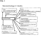
- This application relates to novel fillers and pigments, to compositions including such fillers and pigments, and use of such compositions.
- Fillers and pigments are key components in many industrial markets, such as paper, paints, plastics, concrete, and pharmaceuticals. Fillers and pigments are utilized to reduce cost, improve functionality, and to improve the end use performance.
- One widely used pigment is titanium dioxide (TiO 2 ), which is used to provide brightness and light scattering properties.
- Another widely used pigment is fumed silica , which may be added to some compositions to provide thixotropic attributes, for example, in paint products.
- a different product but with a similar sounding name, is silica fume , which will also be further discussed below.
- PCC precipitated calcium carbonate
- GCC ground calcium carbonate
- Various forms of PCC used include calcite crystalline structures, aragonite crystalline structures, and rhombohedral crystalline structures. Such crystalline structures are generally characterized by low aspect ratios, moderate brightness, and moderate light scattering power. Some of such materials provide improved optical properties. And, some of such materials enhance desired finished product attributes such as paper strength, when used in paper furnish, or print qualities, when used in paper coatings.
- certain paint products, and uses thereof there remains a need for improved light scattering power in fillers and/or pigments.
- Titanium dioxide is one of the most widely used pigments in many industries, such as paints, paper, coatings, and in some composites. Such use may often be to improve brightness, and/or to improve opacity.
- the property of improved opacity means that light scattering properties are improved, which provides a product that is harder to see-through. For example, thin papers may be made more opaque (i.e., made with see-through properties that make it look as if it were actually thicker) by the use of fillers with opacifying properties.
- titanium dioxide has certain limitations. First, it has a very high density of about 4.2 grams per cubic centimeter. Further, in order to keep small titanium dioxide particles from agglomerating in various compositions, dispersants must often be used. Such dispersants usually have deleterious effects on strength properties, especially in the case of coated paper. Also, titanium dioxide particles are highly abrasive. Finally, due to the complexity of some widely used titanium dioxide manufacturing processes, which may include complex separation and purification processes, titanium dioxide is one of the most expensive fillers and/or coating pigments currently available.
- Fumed silica also called pyrogenic silica
- the primary particle surface area of most fumed silica is broadly in the range of from about 50 to about 600 square meters per gram.
- amorphous fumed silica particles may be fused into chainlike secondary particles which, in turn, agglomerate into tertiary 3-dimensional particles.
- fumed silica material is that it is non-porous.
- fumed silica is generally highly thixotropic, and consequently may cause high viscosity compositions, for example when added to paints and coatings. Also, the environmental impacts of the manufacturing processes for fumed silica, and the usually high cost of fumed silica, limit its use.
- Silica fume (also called micro-silica, and not to be confused with the just discussed fumed silica) is an amorphous (i.e., non-crystalline) material. Silica fume is often collected as an ultra-fine powder as a by-product of silicon or ferro-silicon alloy production. Silica fume is generally in the form of spherical particles with an average particle size of about 150 nanometers. Silica fume has a surface area in the range of from about 15 to about 30 square meters per gram. Also, silica fume is a highly pozzolinic material, and thus may be used in cement and concrete to enhance compressive strength, bond strength, and abrasion resistance. However, at this time, silica fume, being a byproduct of production of other materials, is in relatively short supply.
- US2003051841 A1 discloses a method and apparatus for the production of calcium carbonate and calcium silicate in common superatmospheric reactors. It discloses that multiple reactors can be provided for switching production between reactors, and utilizing process waste heat. According to this document, this means that on site production of both PCC and Calcium Silicate Hydrates can be achieved in a paper mill.
- the just discussed fillers and/or pigments are generally of limited purpose. In many applications, each may have a single or limited number of product enhancing properties. Thus, there remains an as yet unmet need for a multi-functional filler and/or pigment that may, in many applications, replace expensive fillers and pigments such as titanium dioxide, fumed silica, or silica fume. It would be advantageous if such a new filler and/or pigment provided a combination of at least some ideal properties, such as (1) high surface ratio, (2) high aspect ratio, (3) high brightness, and (4) high light scattering coefficient.
- the filler includes a synthetic fibrous structured amorphous silica (“SAS”) component and a nano-fibrous crystalline aragonite precipitated calcium carbonate (“FCA”) component, which together may be abbreviated as a "SAS & FCA” nano-composite.
- SAS synthetic fibrous structured amorphous silica
- FCA nano-fibrous crystalline aragonite precipitated calcium carbonate
- such a nano-composite filler maybe characterized as having high surface area (from 40 to 200 meters squared per gram).
- when mixed with water such a nano-composite filler and water mixture results in a pH in a relatively neutral range of from 6.5 to 7.5.
- such unique nano-composites may have a high water absorption rate, for example in the range of from 100% to 300%. In an embodiment, such unique nano-composites (SAS & FCA) may have a high oil absorption rate, for example in the range of from 150% to 300%.
- a nano-composite SAS & FCA material may include at least two distinct components.
- a first component having a haystack shaped structure may be provided.
- the haystack shaped structure may be provided in a configuration that presents a fibrous interstitial appearance, having inner layers and outer layers with irregular interlacing fibers or filaments which are fixed and disposed in relation to each other wherein the interlacing fibers or filaments of at least some of said inner layers are visible to a greater or less degree through the interstices of said outer layers, when said fibrous structure is viewed via microscope.
- such haystack shaped structure may be sized from ten (10) microns to forty (40) microns in size.
- such "hay stack" type structure may be composed of "hair" like nano-fibers of amorphous silica, each having a selected diameter and a selected length.
- the diameter of such amorphous silica fibers of may be in the ten (10) nanometer (nm) range.
- the amorphous silica fibers may be in the range of from three (3) to four (4) microns in length.
- the aspect ratio of such amorphous silica nano-fibers may be approximately 100:1.
- a second component may be provided in a nano-composite (SAS & FCA) material.
- a second component may be provided as an aragonite crystal.
- such an aragonite crystal may have a "needle" shaped fiber structure.
- such aragonite crystals may have an estimated diameter of from 100 nm to 200 nm.
- such aragonite crystals may have a length of from 3 microns to 10 microns.
- Such nano-composite material includes a synthetic fibrous structured amorphous silica component (the "SAS” component), and a nano-fibrous crystalline precipitated calcium carbonate in the aragonite phase component (the “FCA” component).
- SAS synthetic fibrous structured amorphous silica component
- FCA nano-fibrous crystalline precipitated calcium carbonate in the aragonite phase component
- the first structure is amorphous silica, rather than a crystalline calcium silicate hydrate. Further, as noted in FIG. 60 , an EDAX analysis confirmed the first component to be silica.
- the unique nano-composite material described herein includes first component of amorphous silica, and a second component of crystalline aragonite.
- the nano-composite (SAS & FCA) is believed useful as filler, for example, in paints and coatings. And, initial tests have indicated that the nano-composite (SAS & FCA) material is useful as a component of coating compounds, especially in the manufacture of paper and paper products. A myriad of uses may be developed, based on the unique properties of such synthetic nano-composite (SAS & FCA) materials, as indicated in evaluations thus far conducted.
- a unique nano-composite material has been developed which includes both (a) nano-fibrous structured amorphous silica (SAS) and (b) nano-fibrous crystalline aragonite precipitated calcium carbonate (FCA).
- SAS nano-fibrous structured amorphous silica
- FCA nano-fibrous crystalline aragonite precipitated calcium carbonate
- this novel nano-composite material may be referred to herein by the abbreviation "SAS & FCA”.
- the SAS & FCA nano-composite material may be characterized by having high surface area (approximately 40 to 200 m 2 /gram).
- the pH of the SAS & FCA nano-composite material, when mixed with water, is generally in the neutral range of from 6.5 to 7.5.
- an SAS & FCA nano-composite material may have very high water absorption, and very high oil absorption ability, in the range of from 100% to 300% for water absorption, and from 150% to 300% for oil absorption.
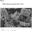
- FIG. 2 a scanning electron microscope (SEM) picture clearly shows two distinct components for a SAS & FCA nano-composite material.
- the first components (an example is seen prominently at the upper right) are haystack shaped structures, which may in an embodiment be from approximately 10 microns to approximately 40 microns in size.
- Such first components includes "hair like" nano-fibers, which in an embodiment may be approximately 10 nanometers (nm) in diameter.
- those hair like nano-fibers may be from 3 microns to 4 microns in length.
- An energy dispersive x-ray spectroscopy (“EDAX”) analysis confirmed the presence of SiO 2 in such hair like nano-fibers.
- the second components are "needle" shaped fiber like structures with an estimated diameter (but not limited thereto) of from 100 nm to 200 nm and with a length generally ranging in size (but not limited thereto) from 3 microns to 10 microns. As shown in FIG.
- the nano-composite material described herein may include structured amorphous silica (SiO 2 ) and fibrous crystalline aragonite carbonate.
- precursor crystalline calcium silicate hydrates such as xonotlite - react and are converted substantially in place into amorphous silica.
- precursor crystalline calcium silicate hydrates may, under conditions described herein, be replaced by amorphous silica.
- the amorphous silica structures, and the associated fibrous crystalline calcium carbonate structures which is in an aragonite phase are produced as a nano-composite material.
- the structure of the nano-composite SAS & FCA material includes an amorphous silica portion having a haystack shaped configuration that presents a fibrous interstitial appearance, having inner layers and superimposed outer layers with irregular interlacing fibers or filaments which are fixed and disposed in relation to each other wherein the interlacing fibers or filaments of at least some of the inner layers of the structured amorphous silica are visible to a greater or less degree through the interstices of outer layers of the structured amorphous silica, when the nano-composite material is viewed via scanning electron microscope.
- the crystalline calcium carbonate portion includes crystalline aragonite structures built within, or on, or within and on, or at least in part extending from, the amorphous silica portion of the nano-composite material.
- the just described "nano-composite" material simultaneously provides certain characteristics that enable filler and/or pigment performance both of amorphous silica and of a crystalline calcium carbonate in an aragonite phase, as will be further understood below in relation to examples provided.
- one unique aspect of the developments described herein may involve the use of various phases of synthetic calcium silicate hydrates (CSH) and the use of carbon dioxide (CO 2 ) under pressure, to manufacture a nano-composite material including both (a) amorphous silica and (b) fibrous crystalline calcium carbonate (which in an embodiment is provided in the aragonite phase).
- CSH synthetic calcium silicate hydrates
- CO 2 carbon dioxide
- FIG. 4 provides an SEM photograph crystalline xonotlite, of one of the calcium silicate hydrate (CSH) starting materials that may be utilized for producing a nano-composite SAS & FCA as described herein.
- the SEM photograph shows secondary particles ranging from 10 microns to 40 microns.
- the secondary particles may be made up of nano-fibers of approximately 10 nm in diameter.
- the secondary particles may be made up of nano-fibers of from 3 microns to 4 microns in length.
- the secondary particles may be made up of nano-fibers having an aspect ratio of 100:1.
- Such starting material may be further identified by the graph of the XRD analysis shown in FIG. 5 .
- the materials is seen to have a major XRD peak at 3.22 angstroms and minor peaks at 2.04 and 8.50 angstroms, which conforms to the characteristics of a xonotlite crystal.
- Other types of calcium silicate hydrates may be used to manufacture a nano-composite material as described herein (e.g, riversidite, or tobermorite, or foshagite), at the present time, it is believed that the conversion efficiency may be higher when using a xonotlite phase calcium silicate hydrate.
- a novel development described herein is a process to convert a crystalline silicate hydrate such as xonotlite into amorphous silica.
- such conversion may be achieved while concurrently producing a synthetic crystalline calcium carbonate in the aragonite phase.
- Such a process may involve the reaction of xonotlite with carbon dioxide (CO 2 ) under pressure, and thus may generally be referred to as a process for pressure carbonation of nano-fibrous calcium silicate hydrates.
- CO 2 carbon dioxide
- the SEM photograph and XRD patterns of the carbonated product resulting from reaction with xonotlite calcium silicate hydrate as a starting material are given in FIGS. 6 and 7 respectively.
- the SEM photograph shows two distinct components in the nano-composite material, namely amorphous silica (within the solid circle) and fibrous crystalline aragonite calcium carbonate (within the dashed oval).
- amorphous silica within the solid circle
- fibrous crystalline aragonite calcium carbonate within the dashed oval.
- the XRD of the nano-composite material identifies only a single crystalline phase, namely aragonite phase calcium carbonate.
- the process described herein includes the use of seed materials for enhancement of reactions, as such materials may promote conversion efficiency.
- the efficiency of a pressure carbonation process may be enhanced by using seed materials and/or promoters or catalysts.
- reaction promoters and/or catalysts may include calcium hydroxide, and/or magnesium hydroxide.
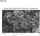
- Various precipitated calcium carbonates that can be manufactured by that process include distinct crystal morphologies, such as calcite scalenohedral as well as calcite rhombohedral of various aspect ratios, and aragonite. SEM photographs of such crystals may be seen in FIGS. 21 , 22 , 23 , and 24 .
- a PCC product manufactured under a pressure carbonation system may be referred to herein as a Super Precipitated Calcium Carbonate ("S-PCC").
- the basic chemistry for producing precipitated calcium carbonates includes the steps of calcination, slaking, and carbonation. The following chemical reactions describe such steps:
- Nano-Composite Cogeneration CaSiO 3 + CO 2 --> CaCO 3 + SiO 2 + ⁇ H ⁇
- the carbonation reaction (equation (3) above) is an equilibrium reaction. Therefore, as the soluble calcium ion is converted to calcium carbonate (CaCO 3 ) precipitate, more dissolution of the calcium hydroxide (Ca(OH) 2 ) takes place from the slurry to increase the concentration of the calcium ion up to the solvent solubility limits (inverse temperature dependent phenomenon), until all of the available calcium hydroxide is dissolved, and all available calcium ions have been converted into calcium carbonate.
- the process is further conducted to form nano-composite SAS & FCA material, as set forth in equation (4), it is of interest that carbon dioxide fixation using synthetic silicates under pressure is a novel method of carbon capture, i.e., fixation by mineralization.
- novel nano-structured materials described herein have some unique properties.
- such properties may make it useful as filler in papermaking operations.
- such use may provide some unusual and beneficial paper properties, or in unusual and beneficial paper coating properties, resulting in superior paper products when made with the nano-structured materials described herein.
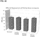
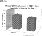
- the nano-structured composite materials described herein may be used at various degrees of substitution for currently used high performance coating pigments such as titanium dioxide (TiO 2 ). In various embodiments, the nano-structured composite materials described herein may be used at various degrees of substitution for calcined and other naturally occurring clays.
- the unique nano-composites described herein may also be used to enhance the performance of various paper properties, such as to improve surface strength of coatings (pick strength), smoothness, appearance, shade, matte finish (lower sheet gloss), print quality, wet pick, and the like.
- the nano-composite material described herein including nano structured amorphous silica and nano- fibrous crystalline aragonite calcium carbonate, fits nearly all of the applicable criteria of an ideal pigment.
- a unique nano-composite including synthetic fibrous structured amorphous silica (SAS) and a nano fibrous crystalline aragonite precipitated calcium carbonate (FCA) is provided.
- such nano-composite may be characterized by having high surface area (approximately 40 to 200 meters squared per gram).
- an embodiment of such unique nano-composite material may have a pH in the neutral pH range of 6.5 to 7.5.
- such nano-composite may have a very high water absorption, say in the range of from 100% to 300%.
- such nano-composite may have a high oil absorption, say in the range of from 150% to 300%.
- the scanning electron microscope (SEM) photograph set forth in FIG. 2 clearly shows two distinct components.
- the first component shown in the photograph is a haystack shaped structure of approximately 10 microns to 40 microns in size.
- the first structure includes "hair like" nano-fibers which in an embodiment may be approximately 10 nm in diameter. In an embodiment, such fibers may be 3 microns to 4 microns in length. Thus, in an embodiment, the aspect ratio of nano-fiber SAS & FCA may be approximately 100:1.
- the second and prominent components in the SEM photograph provided in FIG. 2 are the "needle" shaped fiber structures. In an embodiment, those prominent components have an estimated diameter of from 100 nm to 200 nm, and length ranging from 3 microns to 10 microns.
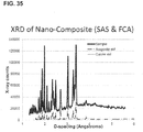
- X-Ray Diffraction (XRD) pattern analysis shown in FIG. 3 identified only a single crystalline component, which component matches the XRD pattern of calcium carbonate in the form of aragonite, with major peaks at 3.276, 3.398, and 1.977 D-spacing (in angstroms).
- EDAX energy dispersive x-ray spectroscopy
- FIG. 60 An energy dispersive x-ray spectroscopy
- nano-composite SAS & FCA which has been developed is a composite of structured amorphous silica (SAS) and fibrous crystalline aragonite (FCA).
- unique nano-composite materials may be produced by the pressure carbonation of one or more of selected synthetic crystalline calcium silicate hydrates (CSH).
- CSH synthetic crystalline calcium silicate hydrates
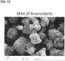
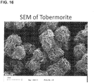
- Suitable synthetic crystalline calcium silicate hydrates may include riversidite (see FIGS. 12 and 13 ), orfoshagite (see FIGS. 14 and 15 ), or tobermorite (see FIGS. 16 and 17 ), or xonotlite (see FIGS. 18 , 19 , and 20 ).
- one or more selected synthetic silicate hydrates are prepared by using hydrothermal reaction of calcareous materials, such as lime, with siliceous materials, such as quartz or diatomaceous earth ("DE").
- the just prepared one or more selected calcium silicate hydrates are subjected to carbonation, under pressurized conditions, to produce a nano-composite structure that includes amorphous silica, generally shaped in the form of the prior crystalline calcium silicate hydrate, and additionally, crystalline calcium carbonate, which in an embodiment, appears in the aragonite phase.
- the process(es) may be carried out in pressurized reactors.
- the manufacturing process of suitable nano-composite materials involves reacting carbon dioxide reaction with synthetic calcium silicate hydrate under pressure.
- the reaction of carbon dioxide under pressurized conditions provides carbonic acid in liquid solution for reaction with the one or more selected calcium silicate hydrates.
- such the second step of formation of nano-composites, i.e., pressurized carbonation may be carried out in the presence of one or more seed materials, such as a selected amount of a previously prepared nano-composite.
- reaction rates may be enhanced by utilization of a combination of selected amounts of calcium hydroxide and magnesium hydroxide.
- the process of pressurized carbonation may be carried out by controlling the starting pH to the range of from 10 to 11.
- Lime slurry is prepared according to generally accepted slaking processes. However, for purposes of further preparation of novel nano-composite SAS & FCA materials, an exception to commonly used methods may be advantageously utilized.
- the lime slurry need not be cooled. Instead, hot lime slurry (usually at approximately 93°C) may be screened and transferred directly to a pressurizable reactor vessel.
- hot lime slurry usually at approximately 93°C
- the solubility of calcium hydroxide is very low in water and is inversely proportional to the temperature of that water. For example, the concentration of lime, as calcium oxide (CaO), in pure water at 0°C is reported to be 0.14%. When the temperature of the water rises to the atmospheric boiling point, 100°C, the solubility of the lime, as calcium oxide (CaO), falls to 0.05%.
- siliceous materials such as quartz, water glass, clay, pure silica, natural silica (sand), natural diatomaceous earth, fluxed calcined diatomaceous earth, or combinations thereof, may be used as source(s) of siliceous material.
- FCDE fluxed calcined diatomaceous earth
- aqueous slurry of siliceous material at a concentration of from 120 grams to 180 grams of silica per liter of slurry can be used.
- silica/quartz (unlike that of calcium hydroxide (Ca(OH) 2 )), is directly proportional to temperature.
- quartz is only slightly soluble up to 100°C. From 100°C to 130°C, quartz starts solubilizing, and around 270° C, a maximum solubility is reached at 0.07%.
- the dissolution of silica may be represented as per the reaction described in equation (5): (5) (SiO 2 )n + 2nH 2 O --> nSi(OH) 4
- the solubility of silica in water may be increased by raising pH, such as by using various additives (e.g., sodium hydroxide).
- the solubilization of silica is also at least to some extent a function of particle size, thus in an embodiment, a smaller particle size, such as may be provided by use of ultra-fine fluxed calcined diatomaceous earth (FCDE) may be advantageous.
- FCDE ultra-fine fluxed calcined diatomaceous earth
- the amount of CaO in a lime slurry and the amount of SiO 2 in a diatomaceous earth slurry may be adjusted to give a selected CaO/SiO 2 mole ratio.
- the concentration of the two slurries (CaO and SiO 2 ) and the final concentration of the mixture may be adjusted by using water so as to provide a selected final concentration, e.g., in an autoclave in experimental apparatus, of between 24 and 120 grams / liter.
- a reaction was carried out in a pressurized reactor vessel, with three major steps:
- a pressurized reactor vessel was cooled down by passing quenching water through an internal cooling coil and external jacketed cooling system.
- the cool down process took from 30 minutes to 60 minutes, in order to reduce the temperature from 230°C to 80°C.
- the inverse solubility of lime in water with respect to temperature has been recognized, and thus utilized in an effort to produce the desired composition and phases of calcium silicate hydrate material.
- calcium silicate hydrate condenses with the remaining Ca(OH) 2 particles to give yet another calcium silicate hydrate, this time with a distinct X-ray diffraction pattern and a crystallochemical formula of Ca 4 (SiO 3 ) 3 (OH) 2 (foshagite).
- the process(es) described herein may produce not only single phase calcium silicate hydrates, but may also produce calcium silicate hydrates having multiple phases therein.
- Different calcium silicate hydrates may be made by changing the lime/silica ratio, slurry concentration, reaction temperature and reaction time.
- the use of different additives like sodium hydroxide, sugar, and chelating compounds may also be utilized and manipulated to create diverse products. More generally, a variety of calcium silicate hydrates ⁇ including xonotlite, tobermorite, riversidite, and foshagite - may be prepared by manipulating the following process parameters:
- Various phases of calcium silicate hydrates were produced by changing the calcium to silica molar ratio (e.g., from 0.75 to 1.35), by changing the reactant concentrations (e.g., from 48 to 120 grams per liter, and by changing the reaction temperature (e.g., from 180°C to 260°C), and by changing the reaction time (e.g., in the range of from 2 hours to 4 hours).
- the CSH products from a selected set of reaction conditions may be cooled from a maximum of 260°C to a minimum of between 180°C and 70°C.
- the process described herein utilizes a hydrothermal reaction that may be carried out under super-atmospheric conditions, using pressurized reactor equipment.
- a reactor used in the lab was a specialized, high pressure, high temperature, two liter reactor vessel. It was fitted with an outside jacketed heater and internal cooling coil system. The reactor was also fitted with an impeller to provide mixing in the reactor (e.g., Rustin 200 impeller).
- the agitator/impeller was connected to a variable speed magnetic drive motor.
- the reactor was fitted with a sample/dip tube, and with a vent system, which was used to maintain pressure at a desired level. The completely assembled reactor was capable of pressures of up to 6,895,000 Pa (68.95 bar). All heating and cooling processes of the reactor were controlled via an external controller.
- the process included reacting lime at approximately 240 grams / liter with a silica source (e.g., diatomaceous earth and/or quartz) at 180 grams / liter.
- a silica source e.g., diatomaceous earth and/or quartz
- the reactions were made in a pressurized reactor over temperature range of 180°C to 250°C and the corresponding steam pressure, ranging from 1,380,000 Pa (13.8 bar) to 4,137,000 Pa (41.37 bar).
- the total reaction time was approximately 4 to 6 hours.
- the resulting slurry concentration ranged from 36 grams per liter to 120 grams per liter.
- CSH crystalline calcium silicate hydrates
- Such crystal phases may be characterized, at least in part, by their: (1) X-Ray diffraction pattern, (2) surface area, (3) water absorption, (4) aspect ratio, and (5) bulk density.
- a graphical representation of typical surface areas of the noted phases of calcium silicate hydrates is provided in FIG. 8 .
- a graphical comparison of the surface area of calcium silicate hydrates (CSH) with titanium dioxide (TiO 2 ) and with precipitated calcium carbonate (PCC) is shown in FIG. 9 .
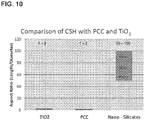
- FIG. 10 A graphical comparison of the aspect ratio of calcium silicate hydrates (SCH) with titanium dioxide (TiO 2 ) and with precipitated calcium carbonate (PCC) is shown in FIG. 10 .
- FIG. 11 A graphical comparison of the bulk density of calcium silicate hydrates (CSH) and titanium dioxide (TiO 2 ), pulp fibers, and calcium carbonate is shown in FIG. 11 .
- Table 2 Characteristics of Various Calcium Silicate Hydrate Phases Crystal Phase Riversideite Tobermorite Xonotlite Foshagite I. X-ray Diffraction Peaks ( ⁇ ) 1. Major Peak 3.055 11.0 3.02 2.93 2. Minor Peeks 3.58, 2.80 3.71, 3.00 2.04, 8.50 2.16,4.96 II.
- the scanning electron microscope (“SEM”) photographic images and corresponding x-ray diffraction ("XRD") patterns of the above noted four different phases of calcium silicate hydrate (CSH) products are shown in FIGS. 12 through 19 .
- the reaction conditions clearly influence the crystal structure and habit, as well as the chemical composition and some physical properties, including surface area, water absorption, aspect ratio, brightness and bulk density.
- such calcium silicate hydrates (CSH) may be produced as macro particles, or as nano-fibers, or as macro fibers with a broad range of surface area, particle sizes, shapes and aspect ratios, as can be seen in the above referenced drawing figures, and as indicated in the above Tables 1 and 2. Additional SEM photographs provided in FIG.
- FIG. 20 illustrates an embodiment that provides an example of a structure ⁇ in the form of a haystack structure ⁇ that is suitable as a calcium silicate hydrate (CSH) that may be useful as a starting material, i.e. a precursor for replacement of material therein with amorphous silica, in the manufacture of a nano-composite (SAS & FCA) containing structured amorphous silica and fibrous calcium carbonate crystals in the form of aragonite.
- CSH calcium silicate hydrate
- Table 3 Process Conditions for manufacture of Synthetic Xonotlite Ca/Si Ratio 1.05 Solids (g/L) 54 Temperature (°C) 230 Reaction Time (hrs) 2 Reaction Volume (L) 4.8 Total Mass (g) 260
- Table 4 Properties of Synthetic Xonotlite pH 11.6 Surface Area (m 2 /g) 137 Water Absorption (%) 315 Oil Absorption (%) 379 X-Ray Diffraction Xonotlite (See FIG. 5 ) Scanning Electron Microscope See FIG. 4 Total Mass (g) 260
- the xonotlite slurry had a pH of 11.6.
- the surface area (BET measurement) for the dry xonotlite was 137 square meters per gram.
- the water and oil absorption of the dry xonotlite were 315% and 379% respectively.
- the scanning electron microscope (SEM) photograph and X-ray diffraction (XRD) pattern of the manufactured xonotlite are shown in FIGS. 4 and 5 respectively.
- the X-ray diffraction pattern set forth in FIG. 5 shows the predominate presence xonotlite.
- the SEM photograph shows, in the circled area, a secondary structure, having a haystack configuration, that provides a fibrous hollow macrosphere structure made up primarily of nano-fibers with layers having interstitial spaces and wherein inner fibers are seen through outer layers of fibers.
- Cogeneration of a nano-composite including structured amorphous silica (SAS) and fibrous crystalline aragonite carbonate (FCA) by pressure carbonation may be accomplished, once one or more selected calcium silicate hydrates are available as a raw material, and a supply of carbon dioxide is available.
- SAS & FCA structured amorphous silica
- FCA fibrous crystalline aragonite carbonate
- the manufacture of a nano-composite (SAS & FCA) material may be done in a cogeneration fashion, that is, the reaction with the xonotlite substrate to replace the same with amorphous silica is carried out at the same time and under the same reaction conditions while fibrous crystalline aragonite is manufactured on, in, or protruding from the substrate CSH starting material, here the xonotlite substrate.
- SAS & FCA nano-composite
- a suitable seed material may include previously generated nano-composite (SAS & FCA) material.
- a suitable seed material may include one or more additional calcium silicate hydrate precursors. The total quantity of seed materials to be added may range from 2% to 20% of the total weight of reactants.
- Catalysts may include a mixture of calcium hydroxide (Ca(OH) 2 ) and magnesium hydroxide (Mg(OH) 2 ).
- the total quantity of catalytic material may range from 2.0% to 10.0% of the total weight of reactants.
- the ratio of calcium hydroxide to magnesium hydroxide may range from 1:1 to 2:1.
- Such catalysts also serve as pH buffers and promoters, and may also help to remove certain impurities from process water.
- the described seed materials, and catalysis/promoters were added to a xonotlite slurry produced as described above.
- a hot silicate slurry ( ⁇ 70 °C)
- the slurry was cooled to a final temperature ranging from 50°C to 75°C.
- the reactor vessel was then pressurized using a non-reactive gas to a pressure ranging from 200,000 to 690,000 Pa (2.0 to 6.9 bar).
- a gas flow containing carbon dioxide (CO 2 ) was injected under pressure into the reactor vessel.
- the carbon dioxide composition of the gas stream varied between 5% and to 100% CO 2 by weight.
- the total gas flow was between 1.3 liters per minute to 7.2 liters per minute, and provided a theoretical reaction rate of between 1.5 grams per liter per minute to 8 grams per liter per minute.
- the pressure was recorded by a pressure probe and shown on a pressure gauge.
- the carbonation reaction between the silicate slurry and carbon dioxide is an exothermic reaction.
- the temperature of the slurry increased.
- the end of the carbonation reaction was indicated by the reactor temperature reaching a peak and then stabilizing to a plateau.
- ⁇ T increase in temperature
- the increase in temperature ( ⁇ T) was in the range of 5°C to 15°C, depending on the reactivity of the silicate, and the composition of the starting calcium silicate hydrate.
- the end of the carbonation reaction was also indicated by plotting the temperature profile.
- Mohr's Salt test One test utilized to establish the nature of products actually manufactured was the Mohr's Salt test. That test involved applying a solution of ammonium iron(II) sulfate (Mohr's Salt, namely (NH 4 ) 2 Fe(SO 4 ) 2 ⁇ 6H 2 O)) to a sample of the nano-composite slurry. The development of a green color indicated the presence of aragonite crystal phase. This test was further confirmed by an X-ray diffraction (XRD) analysis. Another test conducted was the surface area of the final product, using the BET method. In an embodiment, a range of surface areas was found, from 50 square meters per gram to 150 square meters per gram.
- XRD X-ray diffraction
- SAS & FCA structured amorphous silica and fibrous crystalline aragonite carbonate
- a reaction was carried out according to the conditions necessary to produce a nano-composite of structured amorphous silica and fibrous crystalline aragonite carbonate.
- the reaction was carried out in a high pressure 7.5 L reactor manufactured by Parr Instrument Company.
- the pressure carbonation process conditions are given in Table 5 below.
- the resulting nano-composite (SAS & FCA) material properties are summarized in Table 6. Previous work has shown that different sources of silica (Flux calcined diatomaceous earth, ground quartz, and regular diatomaceous earth) will result in different silicate properties.
- the xonotlite formation reaction example above was conducted using a flux calcined Diatomaceous Earth product as a silica source.
- the X-Ray Diffraction pattern and SEM photograph of a resulting nano-composite (SAS & FCA) material are provided in FIGS. 6 and 7 , respectively.
- Table 5 Summary of Process Conditions - Carbonation of Xonotlite Initial Temp (°C) 60 Final Temp (°C) 70 ⁇ T (°C) 10 Volume (L) 4.8 Solids (g/L) 54 Total Mass (g) 260 CO 2 Flow (L/min) 3.6 Start Pressure Pa (bar) 480,000 (4.8)
- the XRD pattern for nano-composite (SAS & FCA) material showed that aragonite was predominantly present, as well as a trace of tobermorite.
- the nano-composite (SAS & FCA) includes both fibrous amorphous silica and fibrous crystalline aragonite.
- FIG. 6 the photographs taken with a scanning electron microscope show two distinct structures in the nano-composite SAS & FCA. A first structure resembles the shape of one of the raw materials, namely the xonotlite calcium silicate hydrate. The second structure resembles crystalline aragonite precipitated calcium carbonate.
- silica component was, after the carbonation reaction, essentially in a non-crystalline, i.e. amorphous form.
- the SEM photograph of the raw materials, namely synthetic xonotlite and its corresponding XRD are given in FIGS. 4 and 5 .
- the SEM photograph of the resulting nano-composite material (SAS & FCA) compound, after the pressure carbonation process, as well as its corresponding XRD, are shown in FIGS. 6 and 7 , respectively.
- a comparison of a selected raw material, and of a sample of the finished product, namely a nano-composite (SAS & FCA) may be instructive.
- the XRD for those xonotlite crystals is provided in FIG 5 .
- the SEM of the carbonated xonotlite showed two distinct structures, namely aragonite (dashed oval) and SiO 2 (solid circle).
- aragonite dashexonotlite
- SiO 2 solid circle
- the pressure carbonation of synthetic calcium silicate hydrates resulted in the unexpected formation of a nano-fibrous crystalline aragonite calcium carbonate (FCA).
- FCA nano-fibrous crystalline aragonite calcium carbonate
- Such crystal structure was also confirmed by the chemical chromatic test using Mohr's Salt (green color).
- the xonotlite i.e., the silica portion of the XRD shown in FIG. 5 was not detected in the XRD pattern of the nano-composite illustrated in the XRD shown in FIG. 7 , it is postulated that the final, carbonated nano-composite (SAS & FCA) material was mostly nano-fibrous structured amorphous silica (SAS), which was produced from the crystalline calcium silicate hydrate xonotlite.
- Step 1 Preparation of Synthetic Calcium Silicate Hydrate ⁇ Xonotlite
- the slurry was then transferred to a 5 liter autoclave, and tested for lime availability in accordance with ASTM method C25, entitled "Standard Test Methods for Chemical Analysis of Limestone, Quicklime, and Hydrated Lime.”
- ASTM method C25 entitled "Standard Test Methods for Chemical Analysis of Limestone, Quicklime, and Hydrated Lime.”
- FCDE fine fluxed calcined diatomaceous earth
- the exact amount of silica slurry added to lime slurry was determined by the lime availability such that a CaO/SiO 2 mol ratio of approximately 1.05 would be maintained.
- the total slurry volume was also adjusted by adding water to a final concentration of 54 grams per liter.
- the autoclave was continuously agitated at a constant speed of 250 rpm.
- the starting temperature of the slurry was approximately 25°C.
- the reactor was heated for approximately 100 minutes in order to reach the target temperature of 230°C.
- the temperature was maintained at 230°C for 2 hours, after which, "quenching" water was flushed through the cooling coil built inside the reactor.
- the cooling process was maintained until the temperature in the reactor reached approximately 80°C (roughly 30 minutes), at which point the reactor was depressurized and opened. Then, the reaction products were transferred to a holding vessel for storage. One portion of the resultant slurry was tested for pH. Another portion of the resultant slurry was dried in an oven at 105°C for 12 hours. During the drying process, the slurry formed hard lumps, which had to be broken up through the use of a mortar and pestle. The powdered, dry product was brushed through a 152 micron (100 mesh) screen to insure product uniformity during testing. The pigment in this example was designated sample batch # MW-2.
- FIG. 4 Some SEM pictures at 1500 times magnification are shown in FIG. 4 .
- the SEM clearly shows the "fibrous” structure of xonotlite.
- the diameter of the "nano-fibers” ranges from 10 nm to 20 nm while the length ranges from 1 microns to 5 microns. Such dimensions result in a material having an aspect ratio of 100:1.
- the SEM also depicts the three dimensional structure of the secondary particles of calcium silicate hydrates. Such secondary structure has a "haystack” type appearance. The structure appears to have been formed by an interlocking of the primary "fibrous” crystals and some inter-fiber bonding due to hydro gel of silica formed during the initial stages of hydro-thermal reaction.
- the secondary particles are fairly stable and do not significantly lose their 3-d structure when subjected to process shear. In addition, these particles also seem to withstand the pressure encountered during the calendaring or finishing operations integral to papermaking and coating.
- the median size of the secondary particles ranges from 10 microns to 40 microns.
- Step 2 Cogeneration of nano-composite (SAS & FCA) having a structured amorphous silica component and a fibrous crystalline calcium carbonate (aragonite) component, by pressure carbonation.
- SAS & FCA nano-composite
- aragonite fibrous crystalline calcium carbonate
- the xonotlite slurry produced in step 1 was placed into a reactor at a slurry concentration of 0.45 pounds per liter.
- the starting carbonation temperature was 60°C.
- the reaction was carried out under a starting pressure of 70 psig. Carbon dioxide gas was bubbled through the reactor. The flow of carbon dioxide was at the rate of 3.6 liters per minute.
- the reaction temperature increased, with the temperature starting at 60°C and ending at approximately 70°C.
- the end of the reaction was indicated when the temperature reached a maximum and then declined.
- the point of inflection in the temperature curve was taken as the completion point of the carbonation reaction.
- the pressure in the vessel spiked due to the incoming but unreacted CO 2 .
- the reactor was first depressurized.
- the reactor was opened and the reaction products were transferred to a holding vessel for storage.
- a portion of the resultant slurry was dried in an oven at 105°C for 12 hours. During the drying process, the slurry formed hard lumps, which had to be broken up through the use of a mortar and pestle.
- the now powdered, dry product was brushed through a 152 micron (100 mesh) screen to insure product uniformity when testing.
- the pigment in this example was designated batch # MW-2-ARA.
- the XRD pattern given in FIG. 7 for an embodiment of the nano-composite SAS & FCA material clearly identifies the presence of crystalline aragonite as a predominant component of the material. However, no XRD peak for a crystalline silica composition (SiO 2 ) was observed.
- the XRD pattern for a nano-composite (SAS & FCA) material showed a peak for precipitated calcium carbonate, namely aragonite (fibrous crystalline aragonite), and a peak for a trace of synthetic calcium silicate hydrate (namely tobermorite).
- SAS & FCA SEM photographs for the nano-composite
- the first structural feature, SiO 2 resembles the original starting material, namely a haystack structure similar to the structure seen in the xonotlite (see the large circle illustrated in FIG. 4 above).
- the second structural feature resembles a crystalline aragonite calcium carbonate (see FIG. 21 ).
- the presence of a silica product was confirmed by an EDAX analysis (see FIG. 60 ). Since the silica product was virtually absent in the X-Ray diffraction (XRD) pattern of the nano-composite (SAS & FCA) as shown in FIG. 7 , it may be inferred that the silica component was essentially non-crystalline, or amorphous.
- a novel composition has been created, in the nature of a nano-composite (SAS & FCA) including a fibrous amorphous silica component and a crystalline calcium carbonate component.
- the fibrous amorphous silica component may be provided in three-dimensional haystack.
- the fibrous amorphous silica component presents a fibrous structure having interstitial spaces between the amorphous silica fibers, with inner layers and outer layers of amorphous silica fibers, and having irregular interlacing amorphous silica fibers or filaments which are fixed in relation to each other.
- the crystalline calcium carbonate component includes aragonite needle structures, which may be grown from, that is, attached to and arising outward from, a portion of the fibrous amorphous silica component.
- the nano-composite (SAS& FCA) structure has a major axis of length L (e.g, L would be the diameter D if the structure were truly spherical, or L would be the major axis of an ovoid, i.e. an elliptically shaped solid, rather similar to irregular solids shown SEM photographs in the various drawing figures) in the range of from 10 microns to 40 microns.
- such novel nano-composites may have a surface area of from 40 meters squared per gram to 200 meters squared per gram. In various embodiments, such novel nano-composites may have a surface area in the range of from 50 meters squared per gram to 150 meters squared per gram. In various embodiments, the amorphous silica fibers may have a length of from 3 microns to 4 microns. In various embodiments the amorphous silica fibers may have a diameter of 10 nm. In various embodiments, the amorphous silica fibers may have an aspect ratio of from 50:1 to 100:1.
- the aragonite needle structures comprise aragonite crystals which may have a length of from 1 micron to 10 microns. In various embodiments, the aragonite crystals may have a length of from 3 microns to 5 microns. In various embodiments, the aragonite needle structure may comprise aragonite crystals having a diameter of from 100 nm to 200 nm. In various embodiments, the aragonite crystals may have an aspect ratio of from 50:1 to 100:1.
- the novel nano-composite composition as set forth herein may be further characterized in that in an X-ray diffraction of the nano-composite composition, a major peak for aragonite appears at approximately 3.22 angstroms. In various embodiments, the novel nano-composite composition described herein may be further characterized in that when mixed with water, the pH is in the range of from 6.5 to 7.5.
- nano-composites (SAS & FCA) materials as described herein may have a composition such that their water absorption characteristic is in the range of from 100% to 300%. In various embodiments, nano-composites (SAS & FCA) materials as described herein may have a composition such that their water absorption characteristic is at least 100%. In various embodiments, nano-composites (SAS & FCA) materials as described herein may have a composition such that their oil absorption characteristic id in the range of from 150% to 300%. In various embodiments, nano-composites (SAS & FCA) materials as described herein may have a composition such that their oil absorption characteristic is in the range of from 200% to 250%.
- Step 1 Preparation of Synthetic Calcium Silicate Hydrate ⁇ Xonotlite
- a multiphase calcium silicate hydrate of was formed by way of the hydrothermal reaction of lime and silica as described in Example 1.
- the difference from Example 1 was that the silica source used in this Example 2 was a non-calcined or natural diatomaceous earth.
- the sample was labeled as batch # MN-2.
- the process conditions for preparation of sample identified as batch # MN-2 are given in Table 12.
- the pigment properties for the sample identified as batch # MN-2 are given in Table 13.
- the graph of the XRD pattern of this sample of crystalline xonotlite is given in FIG. 27 .
- the SEM photograph of this sample of crystalline xonotlite is given in FIG. 26 .
- Step 2 Cogeneration of nano-composite (SAS & FCA) having a structured amorphous silica component and a fibrous crystalline calcium carbonate (aragonite) component, by pressure carbonation.
- SAS & FCA nano-composite
- aragonite fibrous crystalline calcium carbonate
- FIG. 3 The graph of the XRD pattern of a nano-composite SAS & FCA material is provided in FIG. 3 .
- the SEM photograph of such nano-composite SAS & FCA is given in FIG. 2 .
- a multiphase calcium silicate hydrate of was formed by hydrothermal reaction of lime and silica as generally described in Example 1. The differences were that the silica source in this Example 3 was course ground quartz (Sil-Co-Sil 106 from US Silica). The reaction temperature was reduced to 220°C, and the reaction time was increased to 4 hours. Finally, the CaO/SiO 2 molar ratio was increased to 1.30 while the solids composition of the slurry was decreased to 43 grams per liter.
- This calcium silica hydrate (CSH) was made in a 30 gallon reactor with similar temperature probes and an agitator similar to the reactors described above. The sample was labeled as batch # T30-8-078.
- the SEM photograph of this calcium silicate hydrate is shown in FIG. 16 .
- the graph of the XRD pattern of this calcium silicate hydrate is provided in FIG. 17 .
- Step 2 Cogeneration of nano-composite (SAS & FCA) having a structured amorphous silica component and a fibrous crystalline carbonate component, by pressure carbonation.
- SAS & FCA nano-composite having a structured amorphous silica component and a fibrous crystalline carbonate component
- sample ID was batch # T30-8-078-ARA.
- process conditions for cogeneration of sample batch # T30-8-078-ARA are given in Table 18.
- T30-8-078-ARA The pigment properties for sample batch # T30-8-078-ARA are given in Table 19: TABLE 18: Process conditions for preparation of T30-8-078-ARA Batch # Start Temperature (°C) Final Temperature (°C) ⁇ T (°C) Start Pressure Pa (bar) CO 2 Flow Rate (L/min) T30-8-078-ARA 60 70 10 480,000 (4.8) 112 TABLE 19: Properties of Nano-Composite (T30-8-078-ARA) Batch # BET (m 2 /g) pH Water Absorption (%) Oil Absorption (%) Mohr Salt Test T30-8-078-ARA 112 6.8 191 207 Green
- FIG. 30 The SEM photograph of this nano-composite (SAS &FCA) is shown in FIG. 30 .
- the graph of the XRD pattern of this nano-composite is shown in FIG. 31 .
- This novel, multiphase calcium silicate hydrate of was formed by the same hydrothermal reaction of lime and silica as described in Example 3.
- the reaction temperature was increased to 250°C, while the reaction time was reduced to 2 hours.
- the sample was labeled T30-8-082.
- the process conditions for preparation of material designated as batch T30-8-082 are given in Table 20.
- the pigment properties for materials identified as batch T30-8-082 are given in Table 21.
- FIG. 32 The SEM photograph of this calcium silicate hydrate (foshagite) is shown in FIG. 32 .
- the graph of the XRD pattern of this calcium silicate hydrate (foshagite) is shown in FIG. 33 .
- Step 2 Cogeneration of nano-composite (SAS & FCA) having a structured amorphous silica component and a fibrous crystalline calcium carbonate component, by pressure carbonation.
- SAS & FCA nano-composite having a structured amorphous silica component and a fibrous crystalline calcium carbonate component
- seed material was added to the slurry.
- process conditions were generally the same as set forth in Example 1.
- the sample ID was batch # T30-8-082-ARA.
- the process conditions for cogeneration are given in Table 22.
- the pigment properties of this nano-composite SAS & FCA material are given in Table 23.
- the SEM photograph of this nano-composite is provided in FIG. 34 .
- the graph of the XRD pattern of this nano-composite is provided in FIG. 35 .
- an exemplary embodiment of a nano-composite may be manufactured in a straightforward manner.
- a synthetic calcium silicate hydrate is provided.
- the selected synthetic crystalline calcium silicate hydrate includes a base structure.
- Suitable synthetic calcium silicate hydrate may include one or more of (a) xonotlite, (b) foshagite, (c) tobermorite, (d) riversidite, or other synthetic calcium silicate hydrates.
- xonotlite xonotlite
- foshagite tobermorite
- tobermorite tobermorite
- riversidite or other synthetic calcium silicate hydrates.
- the selected synthetic calcium silicate hydrate is mixed with water, sodium hydroxide, and calcium hydroxide, to provide a slurry.
- the slurry is provided to a reactor.
- selected synthetic calcium silicate hydrate(s) may be provided in the slurry in the range of from 36 grams per liter to 120 grams per liter.
- the selected synthetic calcium silicate hydrate(s) may be provided in the slurry in the range of from 48 grams per liter to 96 grams per liter. 3
- the selected synthetic calcium silicate hydrate(s) may be provided in the slurry in the range of from 12 grams per liter to 600 grams per liter.
- the ratio of CaO to SiO 2 in the slurry may be in the range of from 0.75 to 1.3.
- the reactor is pressurized, and carbonation of the selected synthetic crystalline calcium silicate hydrate proceeds by addition of carbon dioxide or carbonic acid to the reactor while agitating the contents of the reactor.
- the pressure of the reactor may be in the range of from 69,000 Pa (0.69 bar) to 2,068,000 Pa (20.68 bar). In an embodiment, the pressure of the reactor may be in the range of from 207,000 Pa (2.07 bar) to 689,000 Pa (6.89 bar). In an embodiment, the pressure of the reactor may be in the range of from 345,000 Pa (3.45 bar) to 621,000 Pa (6.21 bar).
- the pressure of the reactor may be maintained at 483,000 Pa (4.83 bar).
- the carbon dioxide may be provided to the reactor as a gas.
- the carbon dioxide may be present in the gas at from 5% carbon dioxide, to 100% carbon dioxide.
- the carbon dioxide may be present in the gas from 10% to 20%.
- the selected synthetic calcium silicate hydrate composition is transformed to silicon dioxide, thereby forming a fibrous amorphous silica component.
- the fibrous amorphous silica component is provided in three-dimensional haystack configuration that presents a fibrous structure having interstitial spaces between amorphous silica fibers with inner layers and outer layers with irregular interlacing amorphous silica fibers or filaments that are fixed in relation to each other.
- Such reaction proceeds under reaction conditions known to be conducive to the formation of precipitated calcium carbonate in the form of crystalline aragonite.
- the crystalline aragonite are attached to the fibrous amorphous silica component.
- a nano-composite product is produced, wherein the nano-composite product includes both fibrous structured amorphous silica and precipitated calcium carbonate in the form of fibrous crystalline aragonite.
- the nano-composite product may have a major axis of length L in the range from 10 microns to 40 microns, and a surface area of from 40 meters squared per gram to 200 meters squared per gram.
- the reactor may be depressurized, preferably after reactants have been consumed to the extent feasible for the formation of the nano-composite material. Contents of the reactor may then been cooled. In most applications, it may be necessary or convenient to dry the nano-composite product produced in said reactor.
- the step of providing slurry may further include providing seed material.
- seed material may comprise a previously manufactured portion of the nano-composite product itself.
- the seed material may include one or more selected synthetic calcium silicate hydrates.
- the selected synthetic calcium silicate hydrates for use as seed material may include one or more of (a) xonotlite, (b) foshagite, (c) tobermorite, and (d) riversidite.
- the seed material may include calcium hydroxide (Ca(OH) 2 ) in the range of from 2% to 10% by weight.
- the seed material may include magnesium hydroxide (Mg(OH) 2 ) in the range of from 2% to 10% by weight.
- the seed material may include calcium hydroxide (Ca(OH) 2 ) in the range of from 2% to 10% by weight, and magnesium hydroxide (Mg(OH) 2 ) in the range of from 2% to 10% by weight, and wherein the ratio of magnesium hydroxide to calcium hydroxide is in the range of from 1:1 to 2:1.
- a slurry was then run through a 100 (152 micron) to 200 mesh (75 micron) screen to remove large particles, inert material, and reactor scale. After the oversized material was removed, the slurry was then run through a series of unit operations to remove the excess water.
- such processes may include use of a drum filter, and/or press filters, and/or vacuum filtration, and/or spray drying, and/or oven drying, or the like.
- a dry, final product may be obtained. Such dry material may be ground up, e.g using a ball mill or the like, so that the dried solid nano-composite material will pass through a screen of selected size, such as a 152 micron (100 mesh) screen.
- a dry pigment sample was screened, it was then mixed with water to make a high solids slurry with solids ranging from 40% to 60%. That was accomplished with the use of a high shear mixer (such as a Cowlez mixer or Silverson Unit).
- a dispersing agent was added to the water (e.g., a sodium polyacrylamide).
- the amount of dispersing agent added per pound of dry pigment may vary widely depending upon the selected dispersant, but for the stated example, may range from 0.5% to 4%.
- the resulting slurry was passed through a 152 micron (100 mesh) screen to remove large agglomerated particles.
- coating pigments may include coating clays, calcined clays, various forms of calcium carbonates, titanium dioxide, and other materials.
- Different coating pigments may be dispersed individually, either at the manufacturer's plant or the consumer's plant. The order of mixing the various coating pigments is generally not too important, but care should be taken to insure that agglomeration with different pigments does not occur. With the different coating mixtures, the dispersed pigments described above were blended based on a parts method, by weight. Exemplary coating formulations are given in specific examples set forth below.
- binding agents were added to the blend.
- Some synthetic binding agents may include, but are not limited to, styrene-butadiene latex ("SB latex"), styrene-acrylate latex, polyvinyl acetate, polyvinyl alcohol, vinyl acrylic latex, and vinyl acetate-ethylene latex.
- natural binding agents may be selected from various materials such as corn and/or potato starches that have been modified, e.g., by enzyme conversion, or acid thinned, or cation protonated, or oxidized, or hydroxyethylated, or thermally modified, and/or turned into a biopolymer.
- various soy proteins, modified by adding carboxyl groups may be utilized.
- the coating formulation was screened through a selected screen, and in this embodiment, through a 152 micron (100 mesh) screen.
- an exemplary coating composition for coating paper, paperboard products, or label stock may be provided by utilizing the nano-composite material described herein above.
- exemplary coating compositions may be provided using a water slurry including (a) a nano-composite material having a fibrous amorphous silica component, and a crystalline aragonite component.
- the fibrous amorphous silica component may be provided in three-dimensional haystack configuration that presents a fibrous structure having interstitial spaces between amorphous silica fibers, with inner layers and outer layers with irregular interlacing amorphous silica fibers or filaments which are fixed in relation to each other.
- the crystalline calcium carbonate component includes aragonite needle structures.
- the aragonite needle structures arise from the fibrous amorphous silica component.
- the nano-composite material may have a major axis of length L in the range from 10 microns to 40 microns, and a surface area of from 40 meters squared per gram to 200 meters squared per gram.
- a suitable coating composition may also include clay, such as natural or calcined clays, and one or more binders.
- suitable binders may include one or more latex compounds as generally known in the art.
- suitable binders may include one or more protein or protein derivative compounds as generally known in the art.
- a thoroughly mixed coating composition should be passed through a screen of selected size, to assure uniformity and absence of oversize materials.
- a 152 micron (100 mesh) screen may be suitable.
- the amorphous silica fibers in the amorphous silica component may have a length of from 3 microns to 4 microns.
- the amorphous silica fibers in the amorphous silica component may have fibers with a diameter of 10 nm.
- the amorphous silica fibers in the amorphous silica component may have an aspect ratio of from 50:1 to 100:1.
- the aragonite needle structures may include aragonite crystals having a length of from 1 micron to 10 microns. In an embodiment such aragonite crystals may have a length of from 3 microns to 5 microns. In an embodiment, such aragonite needle structures may include aragonite crystals having a diameter of from 100 nm to 200 nm. In an embodiment, the aragonite crystals may have an aspect ratio of from 50:1 to 100:1. In various embodiments of a coating composition, such nano-composite products may have a water absorption characteristic in the range of from 100% to 300%. In various embodiments of a coating composition, such nano-composite products may have a water absorption characteristic of at least 150%.
- such nano-composite products may have an oil absorption characteristic in the range of from 150% to 300%. In various embodiments of a coating composition, such nano-composite products may have an oil absorption characteristic in the range of from 200% to 250%. In various embodiments of a coating composition, such nano-composite products may have a surface area in the range of from 50 meters squared per gram to 150 meters squared per gram.
- a suitable coating composition may further include ground calcium carbonate.
- such nano-composite products may further include at least some titanium dioxide.
- an increase in the amount of said nano-composite material in the coating composition may allow decrease in the quantity of said titanium dioxide necessary to be used in said coating composition, in order to achieve desired properties such as brightness or opacity.
- a specific target brightness may be achieved with selected amount of titanium dioxide in the absence of nano-composite material
- such specific target brightness may also be achieved by replacement of up to 75% of the selected amount of titanium dioxide by addition of an effective amount of the nano-composite material in the coating composition.
- a specific target brightness may also be achieved by replacement of 50% of the selected amount of titanium dioxide by addition of an effective amount of the nano-composite material.
- a specific target brightness may be achieved with selected amount of titanium dioxide in the absence of said nano-composite material
- specific target brightness may also be achieved by replacement of 25% of the selected amount of titanium dioxide by addition of an effective amount of the nano-composite material.
- a coating composition further includes any one or more of (a) titanium dioxide, (b) calcined clay, (c) natural clay, and (d) ground calcium carbonate, and providing an effective amount of the nano-composite material in the coating composition may allow a decrease in the quantity of a selected one or more of (a) titanium dioxide, (b) calcined clay, (c) natural clay, and (d) ground calcium carbonate, in the coating composition, as necessary to meet selected performance or cost objectives.
- the nano-composite (SAS & FCA) material described herein may have, in many cases, beneficial attributes to coating formulations, generally.
- the coating composition comprises a viscosity modifier.
- the coating composition comprises an immobilization time reduction agent.
- the nano-composite material comprises a surface strength improvement agent in a coating composition, as measured by IGT pick test results.
- the nano-composite material comprises a blister resistance improvement agent in a coating composition, as measured by IGT blister test results.
- the nano-composite material comprises an appearance improvement agent.
- the nano-composite material comprises a surface smoothness improvement agent in a coating composition, as measured by Parker Print Smoothness testing.
- the said nano-composite material comprises a whiteness ("L" value) improvement agent in a coating composition.
- the nano-composite material comprises a green shade ("a" value) improvement agent in a coating composition.
- the nano-composite material comprises a blue-white shade improvement agent in a coating composition.
- the nano-composite material comprises a surface finish agent, in a coating composition, whereby a low gloss matte finish may be provided in a coated sheet.
- the nano-composite material comprises a caliper enhancing constituent in a coating composition, wherein a coated sheet of increased caliper is provided.
- an exemplary coating composition may be provided by using the combination of a novel nano-material (SAS & FCA) and a selected synthetic calcium silicate hydrate.
- SAS & FCA novel nano-material
- a selected synthetic calcium silicate hydrate includes aragonite.
- a coating was then applied to a substrate/base in one of several methods. These methods included air knife, rod, blade, and other coating methods. In the lab, a lab rod coater (RK Control Coater) was used. After the coating is applied based on the end-user's requirements, the coated sample was dried, generally using a heated drum (Regal-Arkay ST-22). After the coating was dried, the resulting coated sample was examined for defects or gaps in the coating.
- a coating operation was conducted at a laboratory in Tacoma, Washington.
- the pigment slurries were dispersed using a Silverson disperser then screened through a 152 micron (100 mesh) screen.
- Coating binders were added to the pigment slurry, first a soybean based protein followed by a latex, and the coating formulation was blended with a Silverson low shear mixer.
- the coatings were applied to the paperboard using a RK rod coater and dried in a drum dryer having a Teflon coated, non-stick surface (Regal Arkey ST-22). Coatings were applied over a range of coat weights and then soft nip calendared.
- the test data for each coating condition including the lab control, were plotted as a function of coat weight and normalized to a target coat weight for comparison.
- Example 5 an unbleached Kraft paperboard having a production base coating was as a substrate on which a top coating was applied in the laboratory.
- the TiO 2 range for the top coat control was in the 15 parts to 20 parts range per 100 parts of total dry pigment (by weight), which included calcined clay and # 1 coating clay, with soybean based protein and SB Latex as binder.
- 25%, 50%, and 75% of the TiO 2 was replaced with a nano-composite (SAS & FCA) material in the coating formulation.
- the coating formulation is given below in Table 24.
- FIG. 37 Coating immobilization study results are shown in FIG. 37 .
- the tests were performed using a Dynamic Water Retention (DWR) device.
- FIG. 37 shows how long it takes for the coating to immobilize.
- the data shows that the nano-composite (SAS & FCA) based coatings have a much faster immobilization rate as compared to the control TiO 2 coatings.
- the coated sheets were soft-nip calendared to a target Parker Print Smoothness of 3.0 (PPS 10S).
- PPS 10S Parker Print Smoothness of 3.0
- the calendared sheets were then tested as per the protocol described above.
- the test results are given in Table 25. Then the test data was plotted as a function of coat weight and normalized to a target coat weight of 17 to 19 grams per square meter for comparison.
- the IGT Pick strength and IGT Blister shown in FIGS. 38 and 39 , respectively, show the coating strength for the nano-composite (SAS & FCA) is significantly better (28% and 33% respectively) than the TiO 2 control. It is believed silanol bonding sites may play a role in this strength improvement, which could potentially translate into a lower binder demand.
- the APT Appearance test shown in FIG. 40 , shows that the nano-composite (SAS & FCA) based coating coverage is comparable to the TiO 2 control.
- the ISO Brightness of the nano-composite (SAS & FCA) based coating was several points lower than the TiO 2 control, as indicated in FIG. 41 .
- such characteristics do offer an advantage for reducing dye costs where dye-back methods are sometimes used to improve appearance.
- the "a” value (red-green color balance) showed a slight shift of the coating color to the red (see FIG. 44 ).
- the gloss of the sheets coated with the nano-composite (SAS & FCA) based coating showed a shift towards a matte finish in both the machine direction (MD) and cross direction (CD), as seen in FIGS. 46 and 47 , respectively.
- the addition of the nano-composite (SAS & FCA) in the coating formulation did increase the caliper, as shown in FIG. 48 .
- Coated paperboard samples were sent to Nancy Plowman Associates for print testing to understand the potential print performance of the various nano-composite (SAS & FCA) based coatings as compared to the TiO 2 control.
- Example 6 used an unbleached Kraft paperboard, which was base coated with a 75/25 blend of aragonite S-PCC and nano-composite (SAS & FCA). Together, these two components completely replaced the #2 clay that had been utilized in the base coating control formulation.
- the base coat weight target was 14 to 16 grams per square meter.
- the top coating was a 65/35 blend of aragonite S-PCC and nano-composite (SAS & FCA) at a top coat weight target of 17 to 20 grams per square meter. Both base coatings used the same blend of soybean based protein and SB latex. Both top coatings used the same blend of soybean based protein and SB latex.
- IGT Pick strength and IGT Blister resistance showed a significant improvement (73 % and 44% respectively) for the coating composition utilizing (1) aragonite super precipitated calcium carbonate (S-PCC) and (2) nano-composite (SAS & FCA) based coating, over the control coating.
- the nano-composite (SAS & FCA) structures may retain a hollow macrosphere structure sized and shaped similar to the size and shape of a synthetic calcium silicate hydrate used as a raw material. For example, compare FIGS.
- nano-composite SAS & FCA
- SAS & FCA nano-composite
- FIGS. 12 , 14 , 16 , or 18 the surface strength improvement offers an opportunity to reduce binder demand, when the novel coating formulations including nano-composite (SAS & FCA) materials are utilized.
- the APT Appearance was slightly better for the control, as noted in FIG. 51 .
- the ISO Brightness showed a distinct improvement, when 100% of the TiO 2 was replaced by the nano-composite (SAS & FCA), as indicated in FIG. 52 .
- the "L” value showed a slight drop when 100% of the TiO 2 was replaced with nano-composite (SAS & FCA); see FIG. 53 .
- the "a” value (red-green color balance) showed a shift of the coating color to the red when 100% of the TiO 2 was replaced with nano-composite (SAS & FCA); see FIG. 54 .
- the "b” value (yellow-blue color balance) showed a significant shift to a blue-white shade when 100% of the TiO 2 was replaced with nano-composite (SAS & FCA); see FIG. 55 .
- a bleached, uncoated, wood-free sheet with a basis weight of 70 grams per square meter was used.
- the control coating was made up of 64 dry parts (by weight) of #1 high brightness clay (supplied by Theile), 8 parts (by weight) calcined clay (also supplied by Theile), and 24 parts (by weight) Ground Calcium Carbonate (supplied by OMYA).
- the remaining 4 parts (by weight) of the coating was made up of TiO 2 (supplied by DuPont). Novel coating formulations that were tested were identified as "condition 1", or as "condition 2", or as "condition 3".
- coating formulations included pigments that contained mostly the novel nano-composite structured amorphous silica (SAS) and nano fibrous crystalline aragonite calcium carbonate (FCA).
- some of the coating compositions also included calcium silicate hydrate (foshagite CSH from GR Nano Materials, Tacoma, Washington, USA) (3 parts) and Aragonite S-PCC (from GR Nano Materials, Tacoma, Washington, USA) (3 parts); all parts are by weight.
- Binder in the form of 15.5 parts of SBIR Latex was added with constant stirring to a coating formulation mixture in some embodiments.
- the coating formulation slurry was thoroughly mixed in a Silverson unit for 5 minutes.
- the thoroughly mixed coating formulations were screened through a screen of selected size, normally through a 152 micron (100 mesh) screen, to provide a finished coating composition ready for use.
- 100% of the Ti02 (only 4 parts) was replaced by GR Nano Materials pigments with 6 parts (by weight) of GR Nano Materials products, which alternately was by (1) a mixture of calcium silicate hydrate (foshagite CSH) and nan-composite (SAS & FCA), or (2) by a mixture of calcium silicate hydrate (foshagite CSH) and aragonite S-PCC, or (3) by calcium silicate hydrate (foshagite CSH) alone.
- Table 29 shows the blend procedure and composition utilized for the coating formulations utilized in the embodiments set out in this example.
- the actual coating and drying of the samples was carried out the same as described above.
- the coated sheets were tested for TAPPI Opacity, ISO Opacity as well as scattering coefficient and absorption coefficient (see Table 30).
- Control Condition 1 Condition 2 Condition 3 #1 High Brightness Coating Clay 64.0 62.0 62.0 62.0 Calcined Clay 8.0 8.0 8.0 8.0 Ground Calcium Carbonate 24.0 24.0 24.0 TiO 2 4.0 0.0 0.0 0.0 0.0 Calcium Silicate Hydrate (CSH) Foshaqite 0.0 3.0 3.0 6.0 Nano-Composite (SAS & FCA) 0.0 3.0 0.0 0.0 Aragonite S-PCC 0.0 0.0 3.0 0.0 Total Pigment 100.0 100.0 100.0 100.0 100.0 100.0 100.0 100.0 Latex 15.5 15.5 15.5 Total Binder 15.5 15.5 15.5 Total Pigment + Binder 115.5 115.5 115.5 115.5 Table 30 - Coating Formulation Performance - High Basis Weight Label Stock Control Condition 1 Condition 2 Condition 3 TAPPI Opacity 86.8 86.5 86.7 86.6 % Difference from Control -0.4% -0.2% -0.3% ISO Opacity
- TiO 2 titanium dioxide
- SAS & FCA nano-composite
- CSH calcium silicate hydrate
- CSH calcium silicate hydrate
- aragonite S-PCC condition 2
- FIGS. 56 and 57 show the results of TAPPI Opacity and ISO Opacity, respectively, for the high basis weight label stock coated paper samples.
- Example 8 The coating formulation utilized in Example 8 was generally prepared as set forth in Example 7. However, the label stock paper had a basis weight of 67 grams per square meter of paper. Also, the amounts utilized for the different coating pigments were changed, as shown in Table 31. The making of the coating and the testing of the sheets was generally the same as set forth in Example 7. Table 32 shows the results of opacity testing.
- Control Condition 1 Condition 2 Condition 3 #1 High Brightness Coating Clay 50.0 44.0 44.0 44.0 Calcined Clay 10.0 10.0 10.0 10.0 Ground Calcium Carbonate 28.0 28.0 28.0 0.0 Ti02 12.0 0.0 6.0 6.0 Calcium Silicate Hydrate (CSH) - Foshagite 0.0 9.0 6.0 12.0 Nano-Composite (SAS & FCA) 0.0 9.0 0.0 0.0 Aragonite S-PCC 0.0 0.0 6.0 28.0 Total Pigment 100.0 100.0 100.0 100.0 100.0 100.0 Latex 16.5 16.5 16.5 Total Binder 16.5 16.5 16.5 Total Pigment + Binder 116.5 116.5 116.5 116.5 Table 32 - Coating Performance - Low Basis Weight Label Stock Control Condition 1 Condition 2 Condition 3 TAPPI Opacity 87.9 86.6 86.9 87.8 % Difference from Control -1.5% -1.1% -0.1% ISO Opa
- FIG. 59 shows the results of TAPPI Opacity and ISO Opacity, respectively. While the use of the combination of nano-composite (SAS & FCA) with a foshagite calcium silicate hydrate (CSH) did not yield the desired opacity, the data shows that by replacing the GCC with aragonite S-PCC (see condition 3), it may be possible to replace 50% of the TiO 2 .
- SAS & FCA nano-composite
- CSH foshagite calcium silicate hydrate
- an exemplary coated board, paperboard, or label stock paper may be produced by utilizing novel coating formulations as described above.
- a coated, calendared, paperboard may be provided having (a) one or more layers of pulp (which may in an embodiment be kraft pulp, and may, in an embodiment, be unbleached kraft pulp), and (b) a base coating composition.
- the base coating composition may include a nano-composite material having a fibrous amorphous silica component and a crystalline calcium carbonate component.
- the fibrous amorphous silica component may be provided in three-dimensional haystack configuration that presents a fibrous structure having interstitial spaces between amorphous silica fibers with inner layers and outer layers with irregular interlacing amorphous silica fibers or filaments which are fixed in relation to each other.
- the crystalline calcium carbonate component may be provided in the form of a crystalline calcium carbonate in the aragonite phase, having needle structures. The aragonite needle structures may arise from the fibrous amorphous silica component.
- the nano-composite material may have a major axis of length L in the range from 10 microns to 40 microns, and a surface area of from 40 meters squared per gram to 200 meters squared per gram.
- the base coating composition may also include clay, either natural or calcined, or both.
- the base coating composition may include one or more binders as known in the field, such as a selected latex, and/or a selected protein.
- a coated, calendared paperboard as just set forth above may also include a top coating.
- the top coating may include a nano-composite material having a fibrous amorphous silica component and a crystalline calcium carbonate component.
- the fibrous amorphous silica component may be provided in three-dimensional haystack configuration that presents a fibrous structure having interstitial spaces between amorphous silica fibers with inner layers and outer layers with irregular interlacing amorphous silica fibers or filaments which are fixed in relation to each other.
- the crystalline calcium carbonate component may be provided in the form of a crystalline calcium carbonate in the aragonite phase, having needle structures.
- the aragonite needle structures may arise from the fibrous amorphous silica component.
- the nano-composite material may have a major axis of length L in the range from 10 microns to 40 microns, and a surface area of from 40 meters squared per gram to 200 meters squared per gram.
- the top coating composition may also include clay, either natural or calcined, or both.
- the base coating composition may include one or more binders as known in the field, such as a selected latex, and/or a selected protein.
- a coated, calendared paperboard as just set forth above may have an IGT Pick of at least 100. In various embodiments, a coated, calendared paperboard as just set forth above may have an IGT Blister of least 92. In various embodiments, a coated, calendared paperboard as just set forth above may have an AGT Appearance of at least 8. In various embodiments, a coated, calendared paperboard as just set forth above may have an ISO Opacity of at least 88.0. In various embodiments, a coated, calendared paperboard as just set forth above may have a Tappi Opacity of at least 86.0. Yet more generally, a paper may be provided have a coating composition as set forth herein.
- a paperboard may be provided have a coating composition as set forth herein.
- novel compositions are described herein, in the specification, or in the drawing figures, or both. Methods are described for manufacture of such compositions. And, uses of such compositions are described.
Claims (17)
- Zusammensetzung, enthaltend:
eine Nano-Verbundstruktur mit(a) einer fasrigen amorphen Silikakomponente, wobei die fasrige amorphe Silikakomponente in einer dreidimensionalen Heuhaufenkonfiguration vorgesehen ist, die eine fasrige Struktur präsentiert, die interstitielle Räume zwischen amorphen silikafasern mit inneren Schichten und äußeren Schichten mit irregulären verflechtenden amorphen silikafasern oder -filamenten aufweist, die in Bezug zueinander fixiert sind,(b) einer kristallinen Calciumcarbonatkomponente, wobei die kristalline Calciumcarbonatkomponente Aragonit-Nadelstrukturen enthält, wobei die Aragonit-Nadelstrukturen von der fasrigen amorphen Silikakomponente entstehen und(c) worin die Nano-Verbundstruktur eine Hauptachse mit einer Länge L im Bereich von 10 bis 40 Mikron und eine Oberfläche von 40 bis 200 Quadratmeter pro Gramm aufweist. - Zusammensetzung gemäß Anspruch 1, worina) die amorphen silikafasern eine Länge von 3 bis 4 Mikron haben oderb) die amorphen silikafasern einen Durchmesser von 10 nm haben oderc) die amorphen silikafasern ein Längenverhältnis von 50:1 bis 100:1 haben oderd) die Aragonit-Nadelstrukturen Aragonitkristalle mit einer Länge von 1 bis 10 Mikron, bevorzugt 3 bis 5 Mikron enthalten odere) die Aragonit-Nadelstrukturen Aragonitkristalle mit einem Durchmesser von 100 bis 200 nm enthalten, worin die Aragonitkristalle bevorzugt ein Längenverhältnis von 50:1 bis 100:1 haben.
- Zusammensetzung gemäß Anspruch 1 oder 2, worina) die Zusammensetzung eine Wasserabsorptionseigenschaft im Bereich von 100 oder 300 % hat oderb) die Zusammensetzung eine Ölabsorptionseigenschaft im Bereich von 150 bis 300 %, bevorzugt 200 bis 250 % hat, oderc) die Zusammensetzung eine Oberfläche im Bereich von 50 bis 150 Quadratmeter pro Gramm aufweist.
- Zusammensetzung gemäß Anspruch 1,a) worin die Zusammensetzung eine Wasserabsorptionseigenschaft von wenigstens 100 % hat oderb) weiter dadurch gekennzeichnet, dass in einer Röntgenbeugung der Zusammensetzung ein Hauptpeak für Aragonit bei ungefähr 0,322 Nanometer (3,22 Angström) auftritt.
- Verfahren zur Erzeugung einer Zusammensetzung gemäß Anspruch 1, wobei das Verfahren enthält:Vorsehen eines synthetischen Calciumsilikathydrates mit einer Basenstruktur, wobei die Basenstruktur ein ausgewähltes kristallines Calciumsilikathydrat enthält,Mischen des ausgewählten synthetischen Calciumsilikathydrates mit Wasser, Natriumhydroxid und Calciumhydroxid, unter Erhalt einer Aufschlämmung,Führen der Aufschlämmung zu einem Reaktor,Unterdrucksetzen des Reaktors und Carbonieren des ausgewählten synthetischen kristallinen Calciumsilikathydrates durch Zugabe von Kohlendioxid oder Carbonsäure zu dem Reaktor, während der Inhalt des Reaktors gerührt wird,Extrahieren von Calcium von der Basenstruktur und Transformieren des ausgewählten synthetischen kristallinen Calciumsilikathydrates in Siliciumdioxid zur Bildung der fasrigen amorphen Silikakomponente,Ausfällen des kristallinen Aragonits.
- Verfahren gemäß Anspruch 5,a) weiterhin enthaltend das Ablassen des Drucks im Reaktor oderb) worin das ausgewählt synthetische Calciumsilikathydrat ein oder mehrere von (i) Xonotlit, (ii) Foshagit, (iii) Tobermorit und (iv) Riversidit enthält oderc) worin der Druck des Reaktors im Bereich von 69.000 Pa (0,69 bar) bis 2.068.000 Pa (20,68 bar), bevorzugt 207.000 Pa (2,07 bar) bis 689.000 Pa (6,89 bar), mehr bevorzugt 345.000 Pa (3,45 bar) bis 621.000 Pa (6,21 bar) oder am meisten bevorzugt bei 483.000 Pa (4,83 bar) gehalten wird oderd) worin Kohlendioxid zum Reaktor als Gas geführt wird und das Kohlendioxid bevorzugt in dem Gas von 5 bis 100 %, mehr bevorzugt 10 bis 20 % vorhanden ist, odere) worin das synthetische Calciumsilikathydrat in der Aufschlämmung im Bereich von 12 bis 600 Gramm pro Liter vorgesehen wird, bevorzugt 36 bis 120 Gramm pro Liter, mehr bevorzugt 48 bis 96 Gramm pro Liter, oderf) worin das Verhältnis von CaO zu SiO2 in der Aufschlämmung im Bereich von 0,75 bis 1,3 ist.
- Verfahren gemäß Anspruch 6, Option a), weiterhin enthaltend das Kühlen der Inhalte des Reaktors.
- Verfahren gemäß Anspruch 7, weiterhin enthaltend das Trocknen des Nano-Verbundproduktes, das in dem Reaktor erzeugt ist.
- Verfahren gemäß Anspruch 8, worin der Schritt für den Erhalt der Aufschlämmung weiterhin das Vorsehen eines Keimmaterials enthält.
- Verfahren gemäß Anspruch 9, worina) das Keimmaterial einen zuvor hergestellten Bereich des Nano-Verbundproduktes enthält oderb) das Keimmaterial ein oder mehrere ausgewählte synthetische Calciumsilikathydrate enthält, worin die ausgewählten synthetischen Calciumsilikathydrate bevorzugt ein oder mehrere von (i) Xonotlit, (ii) Foshagit, (iii) Tobermorit und (iv) Riversidit enthalten.
- Beschichtungszusammensetzung für Beschichtungspapier, Kartonprodukte oder Etikettenmaterial, worin die Beschichtungszusammensetzung nach Mischen und Durchleiten durch ein Sieb mit ausgewählter Größe erhältlich ist, worin die Beschichtungszusammensetzung eine Wasseraufschlämmung enthält, die enthält:(a) ein Nano-Verbundmaterial, wobei das Nano-Verbundmaterial eine fasrige amorphe Silikakomponente enthält, wobei die fasrige amorphe Silikakomponente in einer dreidimensionalen Heuhaufenkonfiguration vorgesehen ist, die eine fasrige Struktur mit interstitiellen Räumen zwischen amorphen silikafasern mit inneren Schichten und äußeren Schichten mit irregulären verflechtenden amorphen silikafasern oder -filamenten aufweist, die in Bezug zueinander fixiert sind, und eine kristalline Calciumcarbonatkomponente enthält, wobei die kristalline Calciumcarbonatkomponente Aragonit-Nadelstrukturen enthält, wobei die Aragonit-Nadelstrukturen von der fasrigen amorphen Silikakomponente entstehen, wobei das Nano-Verbundmaterial eine Hauptachse der Länge L im Bereich von 10 bis 40 Mikron und eine Oberfläche von 40 bis 200 Quadratmeter pro Gramm aufweist,(b) Lehm,(c) ein oder mehrere Bindemittel, wobei das eine oder die mehreren Bindemittel einen ausgewählten Latex und/oder ein ausgewähltes Protein enthalten.
- Beschichtungszusammensetzung gemäß Anspruch 11, worina) die amorphen silikafasern eine Länge von 3 bis 4 Mikron haben oderb) die amorphen silikafasern einen Durchmesser von 10 nm haben oderc) die amorphen silikafasern ein Längenverhältnis von 50:1 bis 100:1 haben oderd) die Aragonit-Nadelstrukturen Aragonitkristalle mit einer Länge von 1 bis 10 Mikron, bevorzugt 3 bis 5 Mikron enthalten odere) die Aragonit-Nadelstrukturen Aragonitkristalle mit einem Durchmesser von 100 bis 200 nm haben, wobei die Aragonitkristalle bevorzugt ein Längenverhältnis von 50:1 bis 100:1 haben oderf) das Nano-Verbundprodukt eine Wasserabsorptionseigenschaft im Bereich von 100 bis 300 % oder zumindest 150 % aufweist oderg) das Nano-Verbundprodukt eine Ölabsorptionseigenschaft im Bereich von 150 bis 300 %, bevorzugt 200 bis 250 % hat oderh) das Nano-Verbundprodukt eine Oberfläche im Bereich von 50 bis 150 Quadratmeter pro Gramm hat oderi) die Beschichtungszusammensetzung weiterhin synthetisches kristallines Aragonit enthält, worin das synthetische kristalline Aragonit bevorzugt Aragonit enthält, das unter Druck gebildet ist, oderj) das Sieb mit ausgewählter Größe 149 Mikron-Sieb (100 Mesh-Sieb) enthält oderk) der Lehm calcinierten Lehm enthält oderl) der Lehm natürlichen Lehm enthält oderm) die Beschichtungszusammensetzung weiterhin gemahlenes Calciumcarbonat enthält odern) die Beschichtungszusammensetzung weiterhin zumindest etwas Titandioxid enthält, worin es bevorzugt ist, dass eine Erhöhung einer Menge des Nano-Verbundmaterials in der Beschichtungszusammensetzung eine Verminderung der Menge des Titandioxids in der Beschichtungszusammensetzung ermöglicht odero) die Beschichtungszusammensetzung einen Viskositätsmodifizierer enthält oderp) die Beschichtungszusammensetzung ein Immobilisierungszeit-Reduktionsmittel enthält oderq) das Nano-Verbundmaterial ein Oberflächenfestigkeits-Verbesserungsmittel, gemessen durch IGT-Picktestergebnisse, enthält oderr) das Nano-Verbundmaterial ein Blisterresistenz-Verbesserungsmittel, gemessen durch IGT-Blistertestergebnisses, enthält oders) das Nano-Verbundmaterial ein Aussehen-Verbesserungsmittel enthält odert) das Nano-Verbundmaterial ein Oberflächenglättungs-Verbesserungsmittel, gemessen durch Parker Print Smoothness-Test, enthält, oderu) das Nano-Verbundmaterial ein Weißheit ("L"-Wert)-Verbesserungsmittel enthält oderv) das Nano-Verbundmaterial ein Grünschatten ("a"-Wert)-Verbesserungsmittel enthält oderw) das Nano-Verbundmaterial ein Blau-Weiß-Schatten-Verbesserungsmittel enthält oderx) das Nano-Verbundmaterial ein Oberflächenbearbeitungsmittel enthält, wobei ein mattes Finish mit niedrigem Glanz in einer beschichteten Lage erhalten wird odery) das Nano-Verbundmaterial einen Stärke-Verstärkungsbestandteil in der Beschichtungszusammensetzung enthält, wobei eine beschichtete Lage mit verstärkter Stärke erhalten wird oderz) die Beschichtungszusammensetzung sowohl das Nano-Verbundmaterial als auch ein ausgewähltes synthetisches Calciumsilikathydrat enthält oderaa) die Beschichtungszusammensetzung weiterhin irgendeines oder mehrere von (i) Titandioxid, (ii) calciniertem Lehm, (iii) natürlichem Lehm und (iv) gemahlenem Calciumcarbonat enthält und worin der Erhalt einer effektiven Menge des Nano-Verbundmaterials in der Beschichtungszusammensetzung eine Verminderung der Quantität des einen oder mehreren von (i) Titandioxid, (ii) calciniertem Lehm, (iii) natürlichem Lehm und (iv) gemahlenem Calciumcarbonat in der Beschichtungszusammensetzung ermöglicht.
- Beschichtungszusammensetzung gemäß Anspruch 12, Option n), worin die Beschichtungszusammensetzung eine gewünschte Helligkeit hat und worin die Erhöhung einer Menge des Nano-Verbundmaterials in der Beschichtungszusammensetzung die Menge an Titandioxid in der Beschichtungszusammensetzung vermindert, die notwendig ist, um eine spezifische gewünschte Helligkeit zu erzielen, und worina) eine spezifische gewünschte Helligkeit mit einer ausgewählten Menge an Titandioxid in der Abwesenheit des Nano-Verbundmaterials erzielt wird und worin die spezifische gewünschte Helligkeit alternativ durch Ersatz von bis zu 75 % der ausgewählten Menge an Titandioxid durch Addition einer effektiven Menge des Nano-Verbundmaterials erzielt wird oderb) eine spezifische gewünschte Helligkeit mit der ausgewählten Menge an Titandioxid in der Abwesenheit des Nano-Verbundmaterials erzielt wird und worin die spezifische gewünschte Helligkeit alternativ durch Ersatz von bis zu 50 % der ausgewählten Menge an Titandioxid durch Addition einer effektiven Menge des Nano-Verbundmaterials erzielt wird oder(c) eine spezifische gewünschte Helligkeit mit einer ausgewählten Menge an Titandioxid in der Abwesenheit des Nano-Verbundmaterials erzielt wird und worin die spezifische gewünschte Helligkeit alternativ durch Ersatz von bis zu 25 % der ausgewählten Menge an Titandioxid durch Addition einer effektiven Menge des Nano-Verbundmaterials erzielt wird.
- Beschichteter, kalanderter Karton, enthaltend:(a) eine oder mehrere Schichten von Kraftpulpe,(b) eine Basisbeschichtung, wobei die Basisbeschichtung eine Beschichtungszusammensetzung enthält, enthaltend:(1) ein Nano-Verbundmaterial, wobei das Nano-Verbundmaterial eine fasrige amorphe Silikakomponente, wobei die fasrige amorphe Silikakomponente in einer dreidimensionalen Heuhaufenkonfiguration vorgesehen ist, die eine fasrige Struktur mit interstitiellen Räumen zwischen amorphen silikafasern mit inneren Schichten und äußeren Schichten mit irregulären verflechtenden amorphen silikafasern oder -filamenten aufweist, die in Bezug zueinander fixiert sind, und eine kristalline Calciumcarbonatkomponente enthält, wobei die kristalline Calciumcarbonatkomponente Aragonit-Nadelstrukturen enthält, wobei die Aragonit-Nadelstrukturen von der fasrigen amorphen Silikakomponente entstehen, wobei das Nano-Verbundmaterial eine Hauptachse der Länge L im Bereich von 10 bis 40 Mikron und eine Oberfläche von 40 bis 200 Quadratmeter pro Gramm aufweist,(2) Lehm,(3) ein oder mehrere Bindemittel, wobei das eine oder die mehreren Bindemittel einen ausgewählten Latex und/oder ein ausgewähltes Protein enthalten, worin die Kraftpulpe bevorzugt ungebleichte Kraftpulpe enthält.
- Beschichteter, kalanderter Karton gemäß Anspruch 14, weiterhin enthaltend eine obere Beschichtung, worin die obere Beschichtung enthält:(1) ein Nano-Verbundmaterial, wobei das Nano-Verbundmaterial eine fasrige amorphe Silikakomponente, wobei die fasrige amorphe Silikakomponente in einer dreidimensionalen Heuhaufenkonfiguration vorgesehen ist, die eine fasrige Struktur mit interstitiellen Räumen zwischen amorphen silikafasern mit inneren Schichten und äußeren Schichten mit irregulären verflechtenden amorphen silikafasern oder -filamenten aufweist, die im Bezug zueinander fixiert sind, und eine kristalline Calciumcarbonatkomponente enthält, wobei die kristalline Calciumcarbonatkomponente Aragonit-Nadelstrukturen enthält, wobei die Aragonit-Nadelstrukturen von der fasrigen amorphen Silikakomponente entstehen, wobei das Nano-Verbundmaterial eine Hauptachse der Länge L im Bereich von 10 bis 40 Mikron und eine Oberfläche von 40 bis 200 Quadratmeter pro Gramm aufweist,(2) Lehm,(3) ein oder mehrere Bindemittel, wobei das eine oder die mehreren Bindemittel einen ausgewählten Latex und/oder ein ausgewähltes Protein enthalten, worin der Karton bevorzugta) einen IGT-Pick von wenigstens 100 oderb) einen IGT-Blister von wenigstens 92 oderc) ein AGT-Aussehen von wenigstens 8,d) eine ISO-Opazität von wenigstens 88,0,e) eine Tappi-Opazität von wenigstens 86,0 aufweist.
- Papier oder Karton, enthaltend eine Beschichtungszusammensetzung gemäß Anspruch 11.
- Verwendung der Zusammensetzung gemäß Anspruch 1 zur Beschichtung von Papier oder Karton.
Priority Applications (1)
| Application Number | Priority Date | Filing Date | Title |
|---|---|---|---|
| PL14788390T PL2988955T3 (pl) | 2013-04-26 | 2014-04-26 | Włóknista strukturyzowana amorficzna krzemionka zawierająca strącany węglan wapnia, kompozycje z niej wytworzone i sposoby ich zastosowania |
Applications Claiming Priority (2)
| Application Number | Priority Date | Filing Date | Title |
|---|---|---|---|
| US201361816649P | 2013-04-26 | 2013-04-26 | |
| PCT/US2014/035587 WO2014176579A2 (en) | 2013-04-26 | 2014-04-26 | Fibrous structured amorphous silica including precipitated calcium carbonate, compositions of matter made therewith, and methods of use thereof |
Publications (3)
| Publication Number | Publication Date |
|---|---|
| EP2988955A2 EP2988955A2 (de) | 2016-03-02 |
| EP2988955A4 EP2988955A4 (de) | 2016-12-28 |
| EP2988955B1 true EP2988955B1 (de) | 2021-12-01 |
Family
ID=51788147
Family Applications (1)
| Application Number | Title | Priority Date | Filing Date |
|---|---|---|---|
| EP14788390.4A Active EP2988955B1 (de) | 2013-04-26 | 2014-04-26 | Faserartig strukturierte amorphe kieselsäure mit gefälltem calciumcarbonat, stoffzusammensetzungen daraus und verfahren zur verwendung davon |
Country Status (6)
| Country | Link |
|---|---|
| US (5) | US9637864B2 (de) |
| EP (1) | EP2988955B1 (de) |
| CN (1) | CN105377575B (de) |
| CA (1) | CA2941374C (de) |
| PL (1) | PL2988955T3 (de) |
| WO (1) | WO2014176579A2 (de) |
Families Citing this family (15)
| Publication number | Priority date | Publication date | Assignee | Title |
|---|---|---|---|---|
| FI125278B (fi) * | 2010-08-20 | 2015-08-14 | Upm Kymmene Corp | Menetelmä kalsiumkarbonaatin saostamiseksi sekä menetelmän käyttö |
| US9637864B2 (en) * | 2013-04-26 | 2017-05-02 | Pacific Nano Products, Inc. | Fibrous structured amorphous silica including precipitated calcium carbonate, compositions of matter made therewith, and methods of use thereof |
| WO2015152283A1 (ja) * | 2014-03-31 | 2015-10-08 | 日本製紙株式会社 | 炭酸カルシウム微粒子と繊維との複合体、および、その製造方法 |
| FR3019563B1 (fr) * | 2014-04-03 | 2016-04-29 | Centre Nat Rech Scient | Procede de preparation de fibres macroscopiques de dioxyde de titane par extrusion unidirectionnelle continue, fibres obtenues et applications |
| US20170321105A1 (en) * | 2014-12-17 | 2017-11-09 | Halliburton Energy Services, Inc. | Weighted Composition for Treatment of a Subterranean Formation |
| KR102233533B1 (ko) * | 2016-02-25 | 2021-03-29 | 아사히 가세이 가부시키가이샤 | 비수 전해질 전지용 무기 입자 및 비수 전해질 전지 |
| IT201600130904A1 (it) * | 2016-12-23 | 2018-06-23 | Pirelli | Composizioni elastomeriche comprendenti fibre di silicati a morfologia aghiforme di dimensioni nanometriche e pneumatici per veicoli che le comprendono. |
| DE102018118285B4 (de) * | 2017-08-03 | 2020-04-09 | Schulz Farben- Und Lackfabrik Gmbh | Titandioxidfreies Beschichtungssystem, dessen Verwendung und Verwendung des Komposits |
| CN110065323A (zh) * | 2019-06-03 | 2019-07-30 | 西安石油大学 | 一种聚乙烯醇免酒精润版液及其制备方法 |
| CN110143077A (zh) * | 2019-06-03 | 2019-08-20 | 西安石油大学 | 一种聚乙二醇免酒精润版液及其制备方法 |
| CN110065324A (zh) * | 2019-06-03 | 2019-07-30 | 西安石油大学 | 一种芳樟醇免酒精润版液及其制备方法 |
| CN110103604A (zh) * | 2019-06-03 | 2019-08-09 | 西安石油大学 | 一种柠檬醛免酒精润版液及其制备方法 |
| CN113511665B (zh) * | 2020-04-09 | 2023-05-23 | 厦门大学 | 以水泥和“三废”为原料的零维和一维碳酸钙微纳米复合物产品及复合材料与合成工艺 |
| CN113149022B (zh) * | 2021-04-30 | 2022-07-22 | 南昌大学 | 一种二氧化硅@硅酸钙中空纳米球及其制备方法和应用 |
| EP4183260A1 (de) * | 2021-11-19 | 2023-05-24 | ImerTech SAS | Beschichtungszusammensetzung, die kalziumsilikat und gefälltes teilchenförmiges kalziumkarbonatmaterial enthält. |
Family Cites Families (58)
| Publication number | Priority date | Publication date | Assignee | Title |
|---|---|---|---|---|
| US3660021A (en) | 1970-09-29 | 1972-05-02 | Nl Industries Inc | Preparation of finely divided calcium silicate |
| SE420596B (sv) | 1975-03-25 | 1981-10-19 | Osaka Packing | Formad kropp av amorf kiseldioxid, eventuellt innehallande kalciumkarbonat, sett att framstella en formad kropp av amorf kiseldioxid samt partikel av amorf kiseldioxid for framstellning av en formad kropp |
| US4167423A (en) * | 1975-04-14 | 1979-09-11 | Union Carbide Corporation | Silane reactive mineral fillers |
| US4294810A (en) * | 1978-07-07 | 1981-10-13 | Tokuyama Soda Kabushiki Kaisha | Alkali calcium silicates and process for preparation thereof |
| US4277457A (en) | 1978-07-07 | 1981-07-07 | Tokuyama Soda Kabushiki Kaisha | Alkali calcium silicates and process for preparation thereof |
| EP0166789B1 (de) | 1983-12-28 | 1988-03-23 | Kabushiki Kaisha Osaka Packing Seizosho | Geformter gegenstand aus kalziumsilikat und dessen herstellungsverfahren |
| US4643801A (en) * | 1986-02-24 | 1987-02-17 | Nalco Chemical Company | Papermaking aid |
| US5219660A (en) | 1987-06-01 | 1993-06-15 | Wason Satish K | Precipitated encapsulated paper pigments and methods |
| US5370852A (en) * | 1989-09-25 | 1994-12-06 | Japan Insulation Co., Ltd. | Primary particles of amorphous silica composite material, secondary particles of amorphous silica composite material, shaped bodies thereof and processes for their preparation |
| US5312484A (en) | 1989-10-12 | 1994-05-17 | Industrial Progress, Inc. | TiO2 -containing composite pigment products |
| FI94058C (fi) | 1993-07-20 | 1995-07-10 | Erkki Vaeaenaenen | Menetelmä paperin täyteaineena käytettävän kalsiumkarbonaatti/piidioksidi-seospigmentin valmistamiseksi |
| JP2507920B2 (ja) | 1994-01-17 | 1996-06-19 | 工業技術院長 | けい酸カルシウムを用いた耐酸性濾過助剤の製造方法 |
| US5623013A (en) * | 1994-12-16 | 1997-04-22 | Ube Industries, Ltd. | Xonotlite-reinforced organic polymer composition |
| US6125356A (en) | 1996-01-18 | 2000-09-26 | Rosefaire Development, Ltd. | Portable sales presentation system with selective scripted seller prompts |
| FI105471B (fi) * | 1997-09-08 | 2000-08-31 | Fp Pigments Oy | Menetelmä kalsiumkarbonaattipartikkelien valmistamiseksi |
| US6010619A (en) | 1997-01-22 | 2000-01-04 | Greenvue Company, Llc | FCC process with zeolite and hydrotalcite |
| US6264736B1 (en) * | 1997-10-15 | 2001-07-24 | Board Of Supervisors Of Louisiana State University And Agricultural And Mechanical College | Pressure-assisted molding and carbonation of cementitious materials |
| US6136085A (en) | 1998-10-29 | 2000-10-24 | Chemical Products Corporation | Silica-coated alkaline earth metal carbonate pigment |
| US6251356B1 (en) * | 1999-07-21 | 2001-06-26 | G. R. International, Inc. | High speed manufacturing process for precipitated calcium carbonate employing sequential perssure carbonation |
| US6726807B1 (en) | 1999-08-26 | 2004-04-27 | G.R. International, Inc. (A Washington Corporation) | Multi-phase calcium silicate hydrates, methods for their preparation, and improved paper and pigment products produced therewith |
| EP1104703A1 (de) | 1999-12-03 | 2001-06-06 | Yupo Corporation | Beschichtete Folie |
| CN1161225C (zh) | 2000-01-26 | 2004-08-11 | 国际纸业公司 | 低密度纸板材料、纸容器、纸杯和其制造方法 |
| US6440209B1 (en) | 2000-02-09 | 2002-08-27 | Engelhard Corpoartion | Composite pigments comprising in-situ precipitated metal carbonate crystals |
| JP3392099B2 (ja) | 2000-03-03 | 2003-03-31 | 日鉄鉱業株式会社 | シリカ−炭酸カルシウム複合粒子の製造方法、並びに該粒子を含有する組成物又は構造体 |
| US20030161894A1 (en) | 2001-09-05 | 2003-08-28 | 3P Technologies Ltd. | Precipitated aragonite and a process for producing it |
| US6623555B1 (en) | 2000-06-01 | 2003-09-23 | Jukka P. Haverinen | Composite precipitated calcium carbonate/silicon compound pigment and method of making same |
| US7048900B2 (en) | 2001-01-31 | 2006-05-23 | G.R. International, Inc. | Method and apparatus for production of precipitated calcium carbonate and silicate compounds in common process equipment |
| CN100335567C (zh) | 2002-03-20 | 2007-09-05 | 新加坡纳米材料科技有限公司 | CaCO3/SiO2·nH2O纳米复合颗粒和空心SiO2·nH2O纳米材料及其制备方法 |
| EP1492924A2 (de) * | 2002-04-08 | 2005-01-05 | Ciba Specialty Chemicals Water Treatments Limited | Behandlung gegen im wasser unlösliche klebende verunreinigungen (white pitch) |
| CN100351467C (zh) | 2002-05-03 | 2007-11-28 | 伊梅里斯矿物有限公司 | 纸张涂布颜料 |
| US20040108082A1 (en) | 2002-12-09 | 2004-06-10 | Specialty Minerals (Michigan) Inc. | Filler-fiber composite |
| US7497924B2 (en) * | 2003-05-14 | 2009-03-03 | International Paper Company | Surface treatment with texturized microcrystalline cellulose microfibrils for improved paper and paper board |
| CA2561889C (en) | 2004-03-30 | 2013-07-23 | Nippon Paper Industries, Co., Ltd. | Bulky neutral paper |
| FI120318B (fi) | 2004-06-23 | 2009-09-15 | M Real Oyj | Tärkkelyksen piitä sisältävät komposiitit, menetelmä niiden valmistamiseksi ja käyttö paperin ja kartongin valmistuksessa |
| JPWO2006035878A1 (ja) | 2004-09-30 | 2008-05-15 | 日本製紙株式会社 | 電子写真用転写紙 |
| CA2585348A1 (en) | 2004-10-25 | 2006-05-04 | Nozawa Corporation | Curable composition containing as constituent material silica obtained by decomposing chrysotile and cured object |
| CN101312784B (zh) | 2005-11-23 | 2011-06-22 | 国际壳牌研究有限公司 | 通过矿物碳酸盐化隔离二氧化碳的方法 |
| US7740921B2 (en) * | 2006-07-06 | 2010-06-22 | Hewlett-Packard Development Company, L.P. | Media sheet |
| JP5014709B2 (ja) | 2006-08-28 | 2012-08-29 | 日揮触媒化成株式会社 | 低誘電率非晶質シリカ系被膜の形成方法および該方法より得られる低誘電率非晶質シリカ系被膜 |
| US8182920B2 (en) | 2006-09-21 | 2012-05-22 | Inmat Inc. | Concentrated aqueous nanocomposite dispersions for barrier coatings |
| JP5408562B2 (ja) | 2006-11-30 | 2014-02-05 | 奥多摩工業株式会社 | 軽質炭酸カルシウム、その製造方法およびそれを用いた印刷用紙 |
| EP2053162A1 (de) | 2007-10-26 | 2009-04-29 | SAPPI Netherlands Services B.V. | Beschichtungsformulierung für Offsetpapier und damit beschichtetes Papier |
| PT2070991E (pt) | 2007-12-12 | 2010-10-25 | Omya Development Ag | Processo para produção de carbonato de cálcio precipitado reagido em superfície |
| US7749476B2 (en) | 2007-12-28 | 2010-07-06 | Calera Corporation | Production of carbonate-containing compositions from material comprising metal silicates |
| FI124696B (fi) | 2008-03-07 | 2014-12-15 | Fp Pigments Oy | Pigmenttipartikkelikoostumus, menetelmä sen valmistamiseksi sekä sen käyttö |
| JP5554897B2 (ja) | 2008-03-14 | 2014-07-23 | 日立造船株式会社 | トチュウ由来のバイオポリマー |
| WO2009142739A1 (en) | 2008-05-23 | 2009-11-26 | Dow Global Technologies Inc. | Paper coating composition having nanofiller |
| US8216961B2 (en) | 2008-08-27 | 2012-07-10 | Korea University Research And Business Foundation | Nanoparticles including metal oxide having catalytic activity |
| NO20091130L (no) | 2009-03-17 | 2010-09-20 | Inst Energiteknik | Fremgangsmate ved industriell fremstilling av utfelt kalsium karbonat (CaCO3) fra karbonatholdige bergarter |
| US8900678B2 (en) | 2009-05-29 | 2014-12-02 | Hewlett-Packard Development Company, L.P. | Coated medium for inkjet printing and method of fabricating the same |
| US9346964B2 (en) | 2010-03-17 | 2016-05-24 | Imerys Kaolin, Inc. | Paint comprising hydrophobized minerals and related methods |
| US20110229580A1 (en) | 2010-03-22 | 2011-09-22 | Indian Institute of Technology Bombay, School of Biosciences and Bioengineering | Compositions and methods for nano-in-micro particles |
| EP2371766B1 (de) | 2010-04-01 | 2013-03-06 | Omya Development Ag | Verfahren zum Erhalt von Fällungscalciumcarbonat |
| US8475932B2 (en) | 2010-10-12 | 2013-07-02 | E I Du Pont De Nemours And Company | Compositions of organic acid modified ionomers filled with silica |
| UA116761C2 (uk) | 2011-06-09 | 2018-05-10 | Ратджерс, Те Стейт Юніверсіті Оф Нью Джерсі | Синтетичні сполуки, способи їх виробництва та застосування |
| PL2546410T3 (pl) * | 2011-07-11 | 2014-05-30 | Omya Int Ag | Hydrofobizowane cząstki węglanu wapnia |
| FI20116326A (fi) | 2011-12-28 | 2013-06-29 | Nordkalk Oy Ab | Saostetun karbonaatin käyttö kuitutuotteen valmistuksessa |
| US9637864B2 (en) | 2013-04-26 | 2017-05-02 | Pacific Nano Products, Inc. | Fibrous structured amorphous silica including precipitated calcium carbonate, compositions of matter made therewith, and methods of use thereof |
-
2014
- 2014-04-26 US US14/262,741 patent/US9637864B2/en active Active
- 2014-04-26 CN CN201480023240.1A patent/CN105377575B/zh active Active
- 2014-04-26 US US14/262,742 patent/US9580867B2/en active Active
- 2014-04-26 CA CA2941374A patent/CA2941374C/en active Active
- 2014-04-26 EP EP14788390.4A patent/EP2988955B1/de active Active
- 2014-04-26 PL PL14788390T patent/PL2988955T3/pl unknown
- 2014-04-26 WO PCT/US2014/035587 patent/WO2014176579A2/en active Application Filing
-
2016
- 2016-11-14 US US15/350,615 patent/US9708770B2/en active Active
-
2017
- 2017-03-27 US US15/470,840 patent/US10077363B2/en active Active
-
2018
- 2018-09-17 US US16/133,475 patent/US11447641B2/en active Active
Non-Patent Citations (1)
| Title |
|---|
| None * |
Also Published As
| Publication number | Publication date |
|---|---|
| CA2941374C (en) | 2021-03-16 |
| US9580867B2 (en) | 2017-02-28 |
| CN105377575A (zh) | 2016-03-02 |
| US10077363B2 (en) | 2018-09-18 |
| WO2014176579A2 (en) | 2014-10-30 |
| US20140318418A1 (en) | 2014-10-30 |
| US20170204270A1 (en) | 2017-07-20 |
| EP2988955A2 (de) | 2016-03-02 |
| US9637864B2 (en) | 2017-05-02 |
| EP2988955A4 (de) | 2016-12-28 |
| CN105377575B (zh) | 2017-12-08 |
| US20150050487A1 (en) | 2015-02-19 |
| PL2988955T3 (pl) | 2022-02-14 |
| US20190048197A1 (en) | 2019-02-14 |
| US9708770B2 (en) | 2017-07-18 |
| CA2941374A1 (en) | 2014-10-30 |
| US20170058458A1 (en) | 2017-03-02 |
| WO2014176579A3 (en) | 2015-02-05 |
| US11447641B2 (en) | 2022-09-20 |
Similar Documents
| Publication | Publication Date | Title |
|---|---|---|
| US11447641B2 (en) | Fibrous structured amorphous silica including precipitated calcium carbonate and compositions of matter made therewith | |
| CA2437066C (en) | Method and apparatus for production of precipitated calcium carbonate and silicate compounds in common process equipment | |
| EP1297074B1 (de) | Gefälltes kalziumkarbonat/silicium verbindung enthaltendes kompositpigment | |
| DK2524898T3 (en) | Process for the preparation of precipitated calcium carbonate from fiber pulp mill waste | |
| KR101094545B1 (ko) | 경질 탄산칼슘, 그 제조방법 및 그것을 사용한 제지 충전용 전료 | |
| WO2003055804A1 (en) | Calcium carbonate of different shapes and the preparing process thereof | |
| JP2007070164A (ja) | シリカ−炭酸カルシウム複合粒子の製造方法、該複合粒子又はそれを含有する顔料、填料もしくは紙 | |
| TW200837014A (en) | Lightweight calcium carbonate, process for producing the same, and printing paper containing the same | |
| US6726807B1 (en) | Multi-phase calcium silicate hydrates, methods for their preparation, and improved paper and pigment products produced therewith | |
| Qiu et al. | Synthesis of calcium silicate as paper filler with desirable particle size from desilication solution of silicon-containing waste residues | |
| EP1235758B1 (de) | Multiphasige calsiumsilikathydrate, verfahren zur herstellung derselben und verbesserte papier- und pigment-produkte diese enthaltend | |
| JP2003040618A (ja) | 炭酸カルシウム含有複合基材、その製造方法及びそれを用いた塗工紙 | |
| JPS6311478B2 (de) | ||
| FI117757B (fi) | Tärkkelysasetaattikomposiitit, menetelmä niiden valmistamiseksi ja käyttö paperin ja kartongin valmistuksessa | |
| EP1642873A1 (de) | Verfahren zur Herstellung von Papier enthaltend multiphasige Calciumsilikathydrate | |
| JPS6399397A (ja) | 紙用填料 | |
| KR20110029510A (ko) | 박엽지 충전제 및 그 제조방법 |
Legal Events
| Date | Code | Title | Description |
|---|---|---|---|
| PUAI | Public reference made under article 153(3) epc to a published international application that has entered the european phase |
Free format text: ORIGINAL CODE: 0009012 |
|
| 17P | Request for examination filed |
Effective date: 20151123 |
|
| AK | Designated contracting states |
Kind code of ref document: A2 Designated state(s): AL AT BE BG CH CY CZ DE DK EE ES FI FR GB GR HR HU IE IS IT LI LT LU LV MC MK MT NL NO PL PT RO RS SE SI SK SM TR |
|
| AX | Request for extension of the european patent |
Extension state: BA ME |
|
| DAX | Request for extension of the european patent (deleted) | ||
| RIC1 | Information provided on ipc code assigned before grant |
Ipc: B60C 1/00 20060101AFI20160818BHEP Ipc: D21H 19/12 20060101ALI20160818BHEP Ipc: C09C 1/00 20060101ALI20160818BHEP Ipc: D21H 19/58 20060101ALI20160818BHEP |
|
| A4 | Supplementary search report drawn up and despatched |
Effective date: 20161129 |
|
| RIC1 | Information provided on ipc code assigned before grant |
Ipc: C09C 1/00 20060101ALI20161123BHEP Ipc: D21H 19/12 20060101ALI20161123BHEP Ipc: B60C 1/00 20060101AFI20161123BHEP Ipc: D21H 19/58 20060101ALI20161123BHEP |
|
| STAA | Information on the status of an ep patent application or granted ep patent |
Free format text: STATUS: EXAMINATION IS IN PROGRESS |
|
| 17Q | First examination report despatched |
Effective date: 20180416 |
|
| STAA | Information on the status of an ep patent application or granted ep patent |
Free format text: STATUS: REQUEST FOR EXAMINATION WAS MADE |
|
| STAA | Information on the status of an ep patent application or granted ep patent |
Free format text: STATUS: EXAMINATION IS IN PROGRESS |
|
| 17Q | First examination report despatched |
Effective date: 20190627 |
|
| STAA | Information on the status of an ep patent application or granted ep patent |
Free format text: STATUS: EXAMINATION IS IN PROGRESS |
|
| GRAP | Despatch of communication of intention to grant a patent |
Free format text: ORIGINAL CODE: EPIDOSNIGR1 |
|
| STAA | Information on the status of an ep patent application or granted ep patent |
Free format text: STATUS: GRANT OF PATENT IS INTENDED |
|
| INTG | Intention to grant announced |
Effective date: 20210623 |
|
| GRAS | Grant fee paid |
Free format text: ORIGINAL CODE: EPIDOSNIGR3 |
|
| GRAA | (expected) grant |
Free format text: ORIGINAL CODE: 0009210 |
|
| STAA | Information on the status of an ep patent application or granted ep patent |
Free format text: STATUS: THE PATENT HAS BEEN GRANTED |
|
| AK | Designated contracting states |
Kind code of ref document: B1 Designated state(s): AL AT BE BG CH CY CZ DE DK EE ES FI FR GB GR HR HU IE IS IT LI LT LU LV MC MK MT NL NO PL PT RO RS SE SI SK SM TR |
|
| REG | Reference to a national code |
Ref country code: GB Ref legal event code: FG4D |
|
| REG | Reference to a national code |
Ref country code: AT Ref legal event code: REF Ref document number: 1451406 Country of ref document: AT Kind code of ref document: T Effective date: 20211215 Ref country code: CH Ref legal event code: EP |
|
| REG | Reference to a national code |
Ref country code: FI Ref legal event code: FGE |
|
| REG | Reference to a national code |
Ref country code: IE Ref legal event code: FG4D |
|
| REG | Reference to a national code |
Ref country code: DE Ref legal event code: R096 Ref document number: 602014081531 Country of ref document: DE |
|
| REG | Reference to a national code |
Ref country code: SE Ref legal event code: TRGR |
|
| REG | Reference to a national code |
Ref country code: LT Ref legal event code: MG9D |
|
| REG | Reference to a national code |
Ref country code: NL Ref legal event code: MP Effective date: 20211201 |
|
| REG | Reference to a national code |
Ref country code: AT Ref legal event code: MK05 Ref document number: 1451406 Country of ref document: AT Kind code of ref document: T Effective date: 20211201 |
|
| PG25 | Lapsed in a contracting state [announced via postgrant information from national office to epo] |
Ref country code: RS Free format text: LAPSE BECAUSE OF FAILURE TO SUBMIT A TRANSLATION OF THE DESCRIPTION OR TO PAY THE FEE WITHIN THE PRESCRIBED TIME-LIMIT Effective date: 20211201 Ref country code: LT Free format text: LAPSE BECAUSE OF FAILURE TO SUBMIT A TRANSLATION OF THE DESCRIPTION OR TO PAY THE FEE WITHIN THE PRESCRIBED TIME-LIMIT Effective date: 20211201 Ref country code: BG Free format text: LAPSE BECAUSE OF FAILURE TO SUBMIT A TRANSLATION OF THE DESCRIPTION OR TO PAY THE FEE WITHIN THE PRESCRIBED TIME-LIMIT Effective date: 20220301 Ref country code: AT Free format text: LAPSE BECAUSE OF FAILURE TO SUBMIT A TRANSLATION OF THE DESCRIPTION OR TO PAY THE FEE WITHIN THE PRESCRIBED TIME-LIMIT Effective date: 20211201 |
|
| PG25 | Lapsed in a contracting state [announced via postgrant information from national office to epo] |
Ref country code: NO Free format text: LAPSE BECAUSE OF FAILURE TO SUBMIT A TRANSLATION OF THE DESCRIPTION OR TO PAY THE FEE WITHIN THE PRESCRIBED TIME-LIMIT Effective date: 20220301 Ref country code: LV Free format text: LAPSE BECAUSE OF FAILURE TO SUBMIT A TRANSLATION OF THE DESCRIPTION OR TO PAY THE FEE WITHIN THE PRESCRIBED TIME-LIMIT Effective date: 20211201 Ref country code: HR Free format text: LAPSE BECAUSE OF FAILURE TO SUBMIT A TRANSLATION OF THE DESCRIPTION OR TO PAY THE FEE WITHIN THE PRESCRIBED TIME-LIMIT Effective date: 20211201 Ref country code: GR Free format text: LAPSE BECAUSE OF FAILURE TO SUBMIT A TRANSLATION OF THE DESCRIPTION OR TO PAY THE FEE WITHIN THE PRESCRIBED TIME-LIMIT Effective date: 20220302 Ref country code: ES Free format text: LAPSE BECAUSE OF FAILURE TO SUBMIT A TRANSLATION OF THE DESCRIPTION OR TO PAY THE FEE WITHIN THE PRESCRIBED TIME-LIMIT Effective date: 20211201 |
|
| PG25 | Lapsed in a contracting state [announced via postgrant information from national office to epo] |
Ref country code: NL Free format text: LAPSE BECAUSE OF FAILURE TO SUBMIT A TRANSLATION OF THE DESCRIPTION OR TO PAY THE FEE WITHIN THE PRESCRIBED TIME-LIMIT Effective date: 20211201 |
|
| PG25 | Lapsed in a contracting state [announced via postgrant information from national office to epo] |
Ref country code: SM Free format text: LAPSE BECAUSE OF FAILURE TO SUBMIT A TRANSLATION OF THE DESCRIPTION OR TO PAY THE FEE WITHIN THE PRESCRIBED TIME-LIMIT Effective date: 20211201 Ref country code: SK Free format text: LAPSE BECAUSE OF FAILURE TO SUBMIT A TRANSLATION OF THE DESCRIPTION OR TO PAY THE FEE WITHIN THE PRESCRIBED TIME-LIMIT Effective date: 20211201 Ref country code: RO Free format text: LAPSE BECAUSE OF FAILURE TO SUBMIT A TRANSLATION OF THE DESCRIPTION OR TO PAY THE FEE WITHIN THE PRESCRIBED TIME-LIMIT Effective date: 20211201 Ref country code: PT Free format text: LAPSE BECAUSE OF FAILURE TO SUBMIT A TRANSLATION OF THE DESCRIPTION OR TO PAY THE FEE WITHIN THE PRESCRIBED TIME-LIMIT Effective date: 20220401 Ref country code: EE Free format text: LAPSE BECAUSE OF FAILURE TO SUBMIT A TRANSLATION OF THE DESCRIPTION OR TO PAY THE FEE WITHIN THE PRESCRIBED TIME-LIMIT Effective date: 20211201 Ref country code: CZ Free format text: LAPSE BECAUSE OF FAILURE TO SUBMIT A TRANSLATION OF THE DESCRIPTION OR TO PAY THE FEE WITHIN THE PRESCRIBED TIME-LIMIT Effective date: 20211201 |
|
| REG | Reference to a national code |
Ref country code: DE Ref legal event code: R097 Ref document number: 602014081531 Country of ref document: DE |
|
| PG25 | Lapsed in a contracting state [announced via postgrant information from national office to epo] |
Ref country code: IS Free format text: LAPSE BECAUSE OF FAILURE TO SUBMIT A TRANSLATION OF THE DESCRIPTION OR TO PAY THE FEE WITHIN THE PRESCRIBED TIME-LIMIT Effective date: 20220401 |
|
| PLBE | No opposition filed within time limit |
Free format text: ORIGINAL CODE: 0009261 |
|
| STAA | Information on the status of an ep patent application or granted ep patent |
Free format text: STATUS: NO OPPOSITION FILED WITHIN TIME LIMIT |
|
| PG25 | Lapsed in a contracting state [announced via postgrant information from national office to epo] |
Ref country code: DK Free format text: LAPSE BECAUSE OF FAILURE TO SUBMIT A TRANSLATION OF THE DESCRIPTION OR TO PAY THE FEE WITHIN THE PRESCRIBED TIME-LIMIT Effective date: 20211201 Ref country code: AL Free format text: LAPSE BECAUSE OF FAILURE TO SUBMIT A TRANSLATION OF THE DESCRIPTION OR TO PAY THE FEE WITHIN THE PRESCRIBED TIME-LIMIT Effective date: 20211201 |
|
| 26N | No opposition filed |
Effective date: 20220902 |
|
| PG25 | Lapsed in a contracting state [announced via postgrant information from national office to epo] |
Ref country code: SI Free format text: LAPSE BECAUSE OF FAILURE TO SUBMIT A TRANSLATION OF THE DESCRIPTION OR TO PAY THE FEE WITHIN THE PRESCRIBED TIME-LIMIT Effective date: 20211201 |
|
| REG | Reference to a national code |
Ref country code: CH Ref legal event code: PL |
|
| GBPC | Gb: european patent ceased through non-payment of renewal fee |
Effective date: 20220426 |
|
| REG | Reference to a national code |
Ref country code: BE Ref legal event code: MM Effective date: 20220430 |
|
| PG25 | Lapsed in a contracting state [announced via postgrant information from national office to epo] |
Ref country code: MC Free format text: LAPSE BECAUSE OF FAILURE TO SUBMIT A TRANSLATION OF THE DESCRIPTION OR TO PAY THE FEE WITHIN THE PRESCRIBED TIME-LIMIT Effective date: 20211201 Ref country code: LU Free format text: LAPSE BECAUSE OF NON-PAYMENT OF DUE FEES Effective date: 20220426 Ref country code: LI Free format text: LAPSE BECAUSE OF NON-PAYMENT OF DUE FEES Effective date: 20220430 Ref country code: GB Free format text: LAPSE BECAUSE OF NON-PAYMENT OF DUE FEES Effective date: 20220426 Ref country code: FR Free format text: LAPSE BECAUSE OF NON-PAYMENT OF DUE FEES Effective date: 20220430 Ref country code: CH Free format text: LAPSE BECAUSE OF NON-PAYMENT OF DUE FEES Effective date: 20220430 |
|
| PG25 | Lapsed in a contracting state [announced via postgrant information from national office to epo] |
Ref country code: BE Free format text: LAPSE BECAUSE OF NON-PAYMENT OF DUE FEES Effective date: 20220430 |
|
| PG25 | Lapsed in a contracting state [announced via postgrant information from national office to epo] |
Ref country code: IE Free format text: LAPSE BECAUSE OF NON-PAYMENT OF DUE FEES Effective date: 20220426 |
|
| PG25 | Lapsed in a contracting state [announced via postgrant information from national office to epo] |
Ref country code: IT Free format text: LAPSE BECAUSE OF FAILURE TO SUBMIT A TRANSLATION OF THE DESCRIPTION OR TO PAY THE FEE WITHIN THE PRESCRIBED TIME-LIMIT Effective date: 20211201 |
|
| PGFP | Annual fee paid to national office [announced via postgrant information from national office to epo] |
Ref country code: DE Payment date: 20230414 Year of fee payment: 10 |
|
| PGFP | Annual fee paid to national office [announced via postgrant information from national office to epo] |
Ref country code: SE Payment date: 20230413 Year of fee payment: 10 Ref country code: PL Payment date: 20230414 Year of fee payment: 10 Ref country code: FI Payment date: 20230406 Year of fee payment: 10 |
|
| PG25 | Lapsed in a contracting state [announced via postgrant information from national office to epo] |
Ref country code: HU Free format text: LAPSE BECAUSE OF FAILURE TO SUBMIT A TRANSLATION OF THE DESCRIPTION OR TO PAY THE FEE WITHIN THE PRESCRIBED TIME-LIMIT; INVALID AB INITIO Effective date: 20140426 |