EP2981365B1 - Pulverdichtstrompumpe und entsprechendes betriebsverfahren - Google Patents
Pulverdichtstrompumpe und entsprechendes betriebsverfahren Download PDFInfo
- Publication number
- EP2981365B1 EP2981365B1 EP14711243.7A EP14711243A EP2981365B1 EP 2981365 B1 EP2981365 B1 EP 2981365B1 EP 14711243 A EP14711243 A EP 14711243A EP 2981365 B1 EP2981365 B1 EP 2981365B1
- Authority
- EP
- European Patent Office
- Prior art keywords
- powder
- compressed air
- pump
- chamber
- valve
- Prior art date
- Legal status (The legal status is an assumption and is not a legal conclusion. Google has not performed a legal analysis and makes no representation as to the accuracy of the status listed.)
- Active
Links
- 239000000843 powder Substances 0.000 title claims description 1028
- 238000000034 method Methods 0.000 title claims description 11
- 239000011248 coating agent Substances 0.000 claims description 82
- 238000000576 coating method Methods 0.000 claims description 82
- 238000005507 spraying Methods 0.000 claims description 49
- 229940098458 powder spray Drugs 0.000 claims description 29
- 239000000463 material Substances 0.000 claims description 18
- 238000007599 discharging Methods 0.000 claims description 6
- 239000002184 metal Substances 0.000 claims description 4
- 239000000203 mixture Substances 0.000 claims description 4
- 239000012229 microporous material Substances 0.000 claims description 3
- 230000001105 regulatory effect Effects 0.000 claims 2
- 239000000565 sealant Substances 0.000 description 124
- 230000010349 pulsation Effects 0.000 description 8
- 238000012423 maintenance Methods 0.000 description 5
- 239000002245 particle Substances 0.000 description 5
- 238000013461 design Methods 0.000 description 4
- 239000012530 fluid Substances 0.000 description 4
- 230000002093 peripheral effect Effects 0.000 description 4
- 238000005086 pumping Methods 0.000 description 4
- 239000011148 porous material Substances 0.000 description 3
- 230000035484 reaction time Effects 0.000 description 3
- 238000011144 upstream manufacturing Methods 0.000 description 3
- 238000004140 cleaning Methods 0.000 description 2
- 238000004891 communication Methods 0.000 description 2
- 230000001419 dependent effect Effects 0.000 description 2
- 239000012528 membrane Substances 0.000 description 2
- 239000007921 spray Substances 0.000 description 2
- 238000013022 venting Methods 0.000 description 2
- 230000004913 activation Effects 0.000 description 1
- 238000010276 construction Methods 0.000 description 1
- 238000012937 correction Methods 0.000 description 1
- 230000003247 decreasing effect Effects 0.000 description 1
- 230000007547 defect Effects 0.000 description 1
- 238000011161 development Methods 0.000 description 1
- 230000018109 developmental process Effects 0.000 description 1
- 238000010586 diagram Methods 0.000 description 1
- 230000000694 effects Effects 0.000 description 1
- 238000000265 homogenisation Methods 0.000 description 1
- 238000002360 preparation method Methods 0.000 description 1
- 230000002000 scavenging effect Effects 0.000 description 1
- 238000007493 shaping process Methods 0.000 description 1
Images


Classifications
-
- B—PERFORMING OPERATIONS; TRANSPORTING
- B65—CONVEYING; PACKING; STORING; HANDLING THIN OR FILAMENTARY MATERIAL
- B65G—TRANSPORT OR STORAGE DEVICES, e.g. CONVEYORS FOR LOADING OR TIPPING, SHOP CONVEYOR SYSTEMS OR PNEUMATIC TUBE CONVEYORS
- B65G53/00—Conveying materials in bulk through troughs, pipes or tubes by floating the materials or by flow of gas, liquid or foam
- B65G53/34—Details
- B65G53/66—Use of indicator or control devices, e.g. for controlling gas pressure, for controlling proportions of material and gas, for indicating or preventing jamming of material
-
- B—PERFORMING OPERATIONS; TRANSPORTING
- B05—SPRAYING OR ATOMISING IN GENERAL; APPLYING FLUENT MATERIALS TO SURFACES, IN GENERAL
- B05B—SPRAYING APPARATUS; ATOMISING APPARATUS; NOZZLES
- B05B7/00—Spraying apparatus for discharge of liquids or other fluent materials from two or more sources, e.g. of liquid and air, of powder and gas
- B05B7/14—Spraying apparatus for discharge of liquids or other fluent materials from two or more sources, e.g. of liquid and air, of powder and gas designed for spraying particulate materials
- B05B7/1404—Arrangements for supplying particulate material
- B05B7/1459—Arrangements for supplying particulate material comprising a chamber, inlet and outlet valves upstream and downstream the chamber and means for alternately sucking particulate material into and removing particulate material from the chamber through the valves
-
- B—PERFORMING OPERATIONS; TRANSPORTING
- B05—SPRAYING OR ATOMISING IN GENERAL; APPLYING FLUENT MATERIALS TO SURFACES, IN GENERAL
- B05B—SPRAYING APPARATUS; ATOMISING APPARATUS; NOZZLES
- B05B7/00—Spraying apparatus for discharge of liquids or other fluent materials from two or more sources, e.g. of liquid and air, of powder and gas
- B05B7/14—Spraying apparatus for discharge of liquids or other fluent materials from two or more sources, e.g. of liquid and air, of powder and gas designed for spraying particulate materials
- B05B7/1404—Arrangements for supplying particulate material
- B05B7/1463—Arrangements for supplying particulate material the means for supplying particulate material comprising a gas inlet for pressurising or avoiding depressurisation of a powder container
-
- B—PERFORMING OPERATIONS; TRANSPORTING
- B05—SPRAYING OR ATOMISING IN GENERAL; APPLYING FLUENT MATERIALS TO SURFACES, IN GENERAL
- B05C—APPARATUS FOR APPLYING FLUENT MATERIALS TO SURFACES, IN GENERAL
- B05C19/00—Apparatus specially adapted for applying particulate materials to surfaces
-
- B—PERFORMING OPERATIONS; TRANSPORTING
- B05—SPRAYING OR ATOMISING IN GENERAL; APPLYING FLUENT MATERIALS TO SURFACES, IN GENERAL
- B05C—APPARATUS FOR APPLYING FLUENT MATERIALS TO SURFACES, IN GENERAL
- B05C19/00—Apparatus specially adapted for applying particulate materials to surfaces
- B05C19/06—Storage, supply or control of the application of particulate material; Recovery of excess particulate material
-
- B—PERFORMING OPERATIONS; TRANSPORTING
- B65—CONVEYING; PACKING; STORING; HANDLING THIN OR FILAMENTARY MATERIAL
- B65G—TRANSPORT OR STORAGE DEVICES, e.g. CONVEYORS FOR LOADING OR TIPPING, SHOP CONVEYOR SYSTEMS OR PNEUMATIC TUBE CONVEYORS
- B65G53/00—Conveying materials in bulk through troughs, pipes or tubes by floating the materials or by flow of gas, liquid or foam
- B65G53/04—Conveying materials in bulk pneumatically through pipes or tubes; Air slides
- B65G53/16—Gas pressure systems operating with fluidisation of the materials
- B65G53/18—Gas pressure systems operating with fluidisation of the materials through a porous wall
-
- B—PERFORMING OPERATIONS; TRANSPORTING
- B65—CONVEYING; PACKING; STORING; HANDLING THIN OR FILAMENTARY MATERIAL
- B65G—TRANSPORT OR STORAGE DEVICES, e.g. CONVEYORS FOR LOADING OR TIPPING, SHOP CONVEYOR SYSTEMS OR PNEUMATIC TUBE CONVEYORS
- B65G53/00—Conveying materials in bulk through troughs, pipes or tubes by floating the materials or by flow of gas, liquid or foam
- B65G53/30—Conveying materials in bulk through pipes or tubes by liquid pressure
-
- B—PERFORMING OPERATIONS; TRANSPORTING
- B65—CONVEYING; PACKING; STORING; HANDLING THIN OR FILAMENTARY MATERIAL
- B65G—TRANSPORT OR STORAGE DEVICES, e.g. CONVEYORS FOR LOADING OR TIPPING, SHOP CONVEYOR SYSTEMS OR PNEUMATIC TUBE CONVEYORS
- B65G53/00—Conveying materials in bulk through troughs, pipes or tubes by floating the materials or by flow of gas, liquid or foam
- B65G53/34—Details
- B65G53/58—Devices for accelerating or decelerating flow of the materials; Use of pressure generators
-
- B—PERFORMING OPERATIONS; TRANSPORTING
- B65—CONVEYING; PACKING; STORING; HANDLING THIN OR FILAMENTARY MATERIAL
- B65G—TRANSPORT OR STORAGE DEVICES, e.g. CONVEYORS FOR LOADING OR TIPPING, SHOP CONVEYOR SYSTEMS OR PNEUMATIC TUBE CONVEYORS
- B65G53/00—Conveying materials in bulk through troughs, pipes or tubes by floating the materials or by flow of gas, liquid or foam
- B65G53/34—Details
- B65G53/60—Devices for separating the materials from propellant gas
-
- F—MECHANICAL ENGINEERING; LIGHTING; HEATING; WEAPONS; BLASTING
- F04—POSITIVE - DISPLACEMENT MACHINES FOR LIQUIDS; PUMPS FOR LIQUIDS OR ELASTIC FLUIDS
- F04F—PUMPING OF FLUID BY DIRECT CONTACT OF ANOTHER FLUID OR BY USING INERTIA OF FLUID TO BE PUMPED; SIPHONS
- F04F1/00—Pumps using positively or negatively pressurised fluid medium acting directly on the liquid to be pumped
- F04F1/02—Pumps using positively or negatively pressurised fluid medium acting directly on the liquid to be pumped using both positively and negatively pressurised fluid medium, e.g. alternating
Definitions
- the present invention relates to a powder sealant pump for conveying coating powder according to the preamble of independent claim 1.
- the invention particularly relates to a powder sealant pump for conveying coating powder from a first powder reservoir to a second powder reservoir located downstream of the powder seal pump or a powder spray coating gun or powder coating jet powder downstream of the powder seal pump or the like powder coating powder.
- the publication DE 103 53 968 A1 relates to a coating powder conveyor comprising at least one tubular membrane pump having a powder inlet valve on a powder inlet and a powder outlet valve on a powder outlet of a delivery chamber.
- a suction line is connected to the powder outlet.
- a fluidizing compressed air line conveys fluidizing compressed air into a powder container in the suction region of the suction line.
- the invention further relates to a method for conveying coating powder from a first powder reservoir to a second powder reservoir arranged downstream of the first powder reservoir or to a powder spray coating gun or the like for spraying coating powder arranged downstream of the first powder reservoir.
- Dense phase powder pumps (dense phase powder pumps) of the type mentioned are known in principle from the prior art.
- the document relates EP 1 551 558 A1 a powder sealant pump having a first powder feed chamber and a second powder feed chamber arranged parallel to the first powder feed chamber.
- the two Powder-conveying chambers of the powder-sealing-current pump known from this prior art are delimited both on the intake side and on the delivery side by a mechanically actuated pinch valve arrangement.
- the powder hoses connected to the respective powder delivery chambers of the powder seal pump are deformable with a mechanically actuated plunger to squeeze or open the hose section as needed.
- Each powder feed chamber of the known from this prior art powder seal pump is associated with a filter tube which limits the circumference of the corresponding powder feed chamber.
- the filter tube is permeable to air but not to coating powder and surrounded by an annular chamber to which alternate negative pressure or compressed air can be connected. As a result, coating powder can be alternately sucked into each powder feed chamber or ejected by means of compressed air from the corresponding powder feed chamber.
- the two powder feed chambers arranged parallel to one another are operated in an alternating phase, which means that one of the two powder feed chambers sucks coating powder through the powder inlet of the powder seal pump while the other of the two powder feed chambers releases a coating powder portion previously sucked into the powder feed chamber via the powder outlet of the powder seal pump.
- Pulverdichtstrompumpen with Laen in particular two parallel powder feed chambers are also from the document WO 2005/005060 A2 ( US 2006/0193704 A1 ), the publication DE 199 59 473 A1 ( US 2001/0003568 A1 ) and the publication EP 1 752 399 A1 known.
- powder sealant pumps for conveying coating powder to corresponding devices for spraying coating powder, in particular powder spray coating guns, is disclosed in the document DE 196 11 533 B4 , of the WO 2004/087331 A1 and the EP 1 566 352 A2 known.
- powder sealant pumps of the aforementioned type for the promotion of coating powder became known, trained as injectors powder pumps were used, which are still used today for the promotion of coating powder.
- powder seal pumps of the type mentioned have trained as injectors powder pumps however, has the disadvantage that the powder pumps designed as injectors usually can only convey a smaller amount of coating powder per unit of time.
- powder seal pumps of the type mentioned in practice have prevailed in particular for those applications in which a relatively large amount of coating powder per unit time is to promote.
- the present invention has the object, a powder sealant pump of the type mentioned in such a way that it manages with less maintenance-prone components, while the powder delivery rate of the pump remains unchanged as possible.
- the powder sealant pump for conveying coating powder from a first powder reservoir to a second (with regard to the first powder reservoir) downstream powder reservoir or a downstream powder spray coating gun or the like device for spraying coating powder
- the powder sealant pump as a single-chamber Powder sealant pump is formed and in particular has only a single powder conveying chamber for conveying the coating powder.
- the solution according to the invention is based on the surprising finding that even with a single-chamber powder sealant pump, i. a powder sealant pump, which has only a single powder delivery chamber for conveying the coating powder, a sufficient continuous promotion of coating powder is possible for practical use.
- the powder concentration in the powder path can be homogenized.
- the flow rate of the conveyed powder assumes a constant value in the powder line downstream of the powder outlet of the powder sealant pump and the powder can flow homogeneously through the powder line. It is particularly advantageous if the per pump cycle in the powder path supplied amount of additional compressed air is equal to or at least substantially equal to the per pump cycle fed into the powder feed chamber amount of transport compressed air, which is used for pneumatic ejection of powder portions from the powder feed chamber.
- the pumping frequency of the powder sealant pump designed as a single-chamber powder sealant pump ie the frequency with which coating powder is sucked into the single powder delivery chamber of the powder sealant pump designed as a one-chamber powder sealant pump and then released again, and / or by
- pulsed and coordinated with the pumping frequency of the powder sealant pump constructed as a single-chamber powder sealant pump additional pressurized air is introduced into the powder path downstream of the powder outlet of the powder feed chamber, the flowability of the coating powder conveyed by the powder sealant pump can be improved downstream of the powder sealant pump.
- a uniform powder delivery from the powder seal pump to one of the powder seal downstream pump reservoir or one of the powder seal pump downstream powder spray coating gun or the like means for spraying coating powder possible.
- the present invention provides a particularly easy-to-implement yet effective alternative to conventional powder sealant pumps constructed as multi-chamber powder sealant pumps.
- the powder sealant pump has a powder inlet connected or connectable to the (upstream) first powder reservoir and a powder powder spraying device or the like powder powder spraying apparatus (downstream) connectable powder outlet on.
- the powder inlet of the powder sealant pump may be disposed at a first end portion of the powder sealant flow pump and the powder outlet of the powder sealant flow pump at an opposite second end portion of the powder sealant flow pump, the (single) powder delivery chamber of the powder sealant pump being disposed between the powder inlet and the powder outlet of the powder sealant flow pump.
- the single powder feed chamber of the powder seal current pump according to the invention has a powder inlet at a first end region and a powder outlet at an opposite second end region, the powder seal current pump according to the invention further comprising a powder inlet valve and a powder outlet valve.
- the powder inlet valve Via the powder inlet valve, the powder inlet of the (single) powder delivery chamber is fluidly connected or connectable to the powder inlet of the powder sealant pump.
- the powder outlet of the single powder delivery chamber of the powder sealant pump is connected or connectable to the powder outlet of the powder sealant pump via the powder discharge valve.
- the powder sealant pump has a powder inlet connected or connectable to the first powder reservoir and a powder outlet connected or connectable to the second powder reservoir or powder spray gun or the like, wherein the single powder feed chamber of the powder seal current pump of the present invention has at one end a powder passage, which serves both as a powder inlet and as a powder outlet for the powder feed chamber.
- the powder sealant pump further comprises a powder inlet valve and a powder outlet valve, via the powder inlet valve the powder passage of the single powder feed chamber is fluidly connected or connectable to the powder inlet of the powder sealant pump and via the powder outlet valve the powder passageway single powder delivery chamber is fluidly connected or connectable to the powder outlet of the powder sealant pump.
- the powder sealant pump further comprises a distributor in order to connect the powder passage of the powder feed chamber with the powder inlet valve on the one hand and the powder outlet valve on the other hand in terms of flow. It is conceivable here, in particular, to use a Y-piece as the distributor. Of course, other embodiments come into question for this purpose.
- a control device is furthermore provided, which is designed such that it alternately activates the powder inlet valve and / or the powder outlet valve of the powder sealant pump.
- the control device is preferably further configured to alternately apply an overpressure and a negative pressure in the (single) powder feed chamber of the powder seal current pump.
- the (single) powder feed chamber of the powder seal pump is preferably associated with a gas path through which the powder feed chamber alternately with a vacuum line or vacuum source for sucking coating powder into the powder feed chamber through the open powder inlet valve while the powder outlet valve is closed, or with a pneumatic line or compressed air source for pneumatic ejection a powder portion present in the powder feed chamber through the open powder outlet valve, while the powder inlet valve is closed, is connectable.
- the control device is designed to switch the single powder feed chamber alternately to suction and ejection of powder.
- the aforementioned gas path has a suction air opening and a compressed air opening in a housing peripheral wall of the powder delivery chamber, wherein preferably also a microporous filter element, preferably in the form of a filter tube is provided which at least a partial length or preferably the entire length of the Powder feed chamber forms the peripheral wall of the powder feed chamber and separates the powder chamber of an annular chamber.
- the annular chamber is formed between the outer periphery of the filter element preferably designed as a filter tube and the inner circumference of the housing peripheral wall and surrounds the filter element preferably designed as a filter tube.
- the filter element preferably designed as a filter tube, is permeable to air but not to coating powder because of its small pore size. It is preferably made of a sintered material.
- the suction air port opens into the annulus near the powder outlet and the compressed air port opens into the annulus near the powder inlet.
- the powder inlet valve and the powder outlet valve are the (single) powder delivery chamber present in the powder seal current pump according to the invention preferably each designed as a pinch valve, in particular of the construction, which have a flexible elastic hose as a valve channel, said flexible elastic hose for closing the corresponding valve by means of actuating compressed air in a pressure chamber surrounding the hose is fauxquetschbar.
- the powder inlet valve designed as a pinch valve and the powder outlet valve designed as a pinch valve each have a pinch valve housing with a powder inlet and a powder outlet and with an elastically deformable valve element, preferably in the form of a tube section.
- the valve element should be arranged in the interior of the pinch valve housing such that the powder inlet of the pinch valve can be brought into fluid communication with the powder outlet of the pinch valve via the valve element formed as a tube section.
- the pinch valve housing has at least one connection for supplying compressed air (actuating compressed air) in the space formed between the inner wall of the pinch valve housing and the valve element arranged in the interior of the pinch valve housing.
- compressed air actuating compressed air
- an overpressure is formed in the space between the inner wall of the pinch valve housing and the valve element, as a result, the valve element is compressed in the radial direction and the pinch valve is closed.
- the valve element returns to its initial state, so that there is a fluid connection between the powder inlet of the pinch valve and the outlet of the pinch valve via the valve element.
- the pinch valve housing has at least one connection for applying a negative pressure in the interior of the pinch valve housing as required in order to reduce the opening time of the pinch valve in this way.
- the quantity of powder which can be conveyed per unit of time by the powder seal current pump according to the invention depends on several parameters, in particular on the size (volume) of the powder feed chamber, the frequency with which coating powder sucked into the powder delivery chamber and then discharged again, the strength (height) of the vacuum applied to the suction of the coating powder in the powder feed chamber, the opening period of the powder inlet valve during the suction phase and the flow resistance in the powder lines upstream and in particular downstream of the powder seal.
- the flow resistance in the powder lines upstream and in particular downstream of the powder seal pump are particularly dependent on the length and the internal cross-section of the powder lines, usually powder hoses.
- the delivery frequency of the powder sealant pump depends on the frequency with which coating powder is sucked into the powder delivery chamber and then released again or can be dispensed.
- the powder sealant pump is structurally designed in accordance with preferred implementations of the invention Reaction time for switching from a suction phase during which the powder feed chamber of the single-chamber powder sealant pump is connected to a vacuum source, and a discharge phase during which the powder feed chamber of the single-chamber powder sealant pump is connected to a compressed air source or transport compressed air source can be shortened accordingly so that ultimately the delivery frequency of the powder seal pump can be increased.
- a negative pressure in the powder feed chamber at the same time as, or preferably by a certain delay time later than a control signal for opening the arranged at the powder inlet of the powder feed chamber powder inlet valve is applied, so that the structure the negative pressure in the powder delivery chamber begins at the same time as the opening of the powder inlet valve at the earliest, but preferably by the said predetermined delay time later than the opening of the powder inlet valve.
- this example does not exclude the use of other delay times and cycle times for the powder sealant pump.
- the powder inlet valve provided at the powder inlet of the powder feed chamber and the powder outlet valve provided at the powder outlet of the powder feed chamber are each designed as a pneumatically controllable pinch valve.
- corresponding control valves are used, with which in a coordinated manner actuating compressed air is supplied to the pinch valves.
- the length of the pneumatic control lines to the pinch valves is as short as possible in order to achieve that upon actuation of the corresponding pinch valves, i. can be minimized when supplying actuating compressed air or when applying a negative pressure or when venting the corresponding pinch valve housing, reaction delay times.
- a material block preferably composed of a plurality of modules is provided in which the single powder feed chamber of the powder seal current pump is formed or on which the only one Powder delivery chamber of the powder sealant pump is arranged, wherein advantageously also the powder inlet valve and the powder outlet valve of the (single) powder delivery chamber of the powder sealant pump are arranged on this block of material.
- the corresponding control valves which are used for the pneumatic activation of the powder inlet and powder outlet valve, in each case directly connected to the powder inlet valve or the powder outlet valve via compressed air channels formed in the material block, are connected directly to the supply and discharge of actuating air to ensure the powder inlet or powder outlet valve designed as a pinch valve.
- control valves which are fluidly connected to the (single) powder feed chamber of the powder compacting pump according to the invention for the supply of transport compressed air (during the dispensing phase of the powder seal pump) and vacuum (during the suction phase of the powder seal pump) the material block are arranged and directly connected by means of channels, which are formed in the block of material, with the single powder feed chamber directly in terms of flow.
- the length of the pneumatic control lines to the pinch valves and the length of the air ducts to the powder delivery chamber are shortened as far as possible in order to ensure that upon actuation of the corresponding pinch valves, i. can be minimized when supplying actuating compressed air or when applying a negative pressure or when venting the corresponding pinch valve housing, reaction delay times.
- the reaction time of the powder sealant pump according to the invention can be shortened and thus the delivery frequency can be increased by ensuring that during the suction phase of the powder sealant pump, that is, when a negative pressure is applied in the powder delivery chamber, this at the earliest simultaneously with the opening of the Powder inlet of the powder feed chamber arranged powder inlet valve begins.
- the pump frequency can be increased by providing the pneumatic actuation of the powder inlet valve designed as a pinch valve or of the outlet valve designed as a pinch valve Supplying and discharging of actuating compressed air to the pinch valves is shortened as far as possible.
- the path length of the channels or the channel for supplying the conveying compressed air to the single powder conveying chamber or the path length of the channels or the channel for applying a vacuum in the powder conveying chamber is shortened. In this way, reaction delay times can be reduced when the powder inlet valve or the powder outlet valve is activated, and when in the single powder feed chamber during the suction phase, a vacuum or during the discharge phase, an overpressure is applied.
- an auxiliary compressed air inlet device is used.
- This additional compressed air inlet device opens at at least one point in the powder path between the Pulverauslassventil associated with the single powder delivery chamber and the powder outlet of the Pulverdichtstrompumpe or preferably immediately downstream of the Pulverauslasses the Pulverdichtstrompumpe and serves to supply additional compressed air as needed, which serves as additional transport compressed air.
- additional compressed air pressure is additionally fed at suitable times or events by the auxiliary compressed air inlet device immediately before or after the powder outlet of the powder seal pump.
- a filter tube is preferably provided, through which the powder path between the powder outlet valve and the powder outlet of the powder sealant pump extends at least in regions.
- the powder path becomes downstream the Pulverauslassventils the powder seal pump over a portion of its length passed through the filter tube.
- the filter tube is permeable to compressed air but not to the particles of the coating powder. It is advisable to form the filter tube of microporous material, such as sintered material.
- the filter tube forms a peripheral wall around the powder path and thus a relatively large area through which even small amounts of additional compressed air can flow homogeneously through the filter tube into the powder path and influence powder particles in terms of homogenizing the powder concentration.
- the filter tube has a circumference of at least 180 ° and a channel wall inner surface forms at least 180 ° of Pulverwegiscuses.
- the additional compressed air inlet device without filter element, in particular filter tube.
- the filter element or filter tube only serves to prevent powder particles from being able to penetrate into an additional compressed air line connected to the additional compressed air inlet device.
- additional compressed air is preferably introduced into the powder path downstream of the powder outlet valve of the powder sealant flow pump via the additional compressed air inlet device.
- the pulse frequency of the additional compressed air should in this case be at least equal to the frequency of the powder delivery chamber, with which powder portions are discharged from the powder delivery chamber.
- the pulse frequency of the additional compressed air is the same as the frequency of the powder delivery chamber, ie the frequency with which powder portions are discharged from the powder delivery chamber.
- this device for supplying additional compressed air is advantageously designed such that the additional compressed air of the at least one additional compressed air inlet device with respect to the powder delivery cycle of the powder delivery chamber out of phase feed.
- the additional compressed air is fed into the powder path after the powder outlet valve whenever the powder outlet valve is closed.
- a compressed air source for operating the powder sealant pump
- the compressed air flow pump continuously supplies compressed air
- a manifold is provided, for example in the form of a three-way valve or the like, to the continuously discharged from the compressed air source compressed air alternately the powder feed chamber and the additional compressed air inlet device supply.
- the single powder feed chamber of the powder sealant pump has at least one air exchange opening via which the powder feed chamber can be temporarily exposed to transport compressed air for ejecting powder portions from the powder feed chamber during the discharge phase.
- the device for supplying additional compressed air to the at least one additional compressed air inlet device a switching element, in particular a three / two-way valve or the like switching valve, via which compressed air from a common compressed air source alternately the at least one air exchange opening of the powder feed chamber or the at least one additional compressed air inlet device can be fed.
- the device for supplying additional compressed air to the at least one additional compressed air inlet device is designed such that the per pump cycle of the at least one additional compressed air inlet device supplied amount of additional compressed air in particular as a function of the per pump cycle of the at least one air exchange opening of the powder feed chamber supplied amount of transport compressed air is adjustable.
- the device for supplying additional compressed air to the at least one additional compressed air inlet device is configured to set the amount of additional compressed air fed per pump cycle of the at least one additional compressed air inlet device so that the per pump cycle over the at least one additional compressed air Inlet device fed into the powder path amount of additional compressed air is substantially equal to the per pump cycle via the at least one air exchange opening in the powder feed chamber fed amount of transport compressed air.
- substantially equal in this context means that the amount of additional compressed air fed per pump cycle deviates by at most 15% from the amount of transport compressed air fed into the powder path or into the powder feed chamber per pump cycle. The smaller the deviation, the more uniformly the flow velocity of the powder-air mixture in the powder conduit downstream of the powder outlet of the powder seal pump can be adjusted.
- the present invention is based on the finding that it is advantageous to feed additional compressed air as additional transport compressed air at the powder outlet of the powder sealant pump, wherein downstream of the powder outlet of the powder sealant pump, the powder-air mixture becomes more homogeneous the powder conduit flows when the amount of additional compressed air fed into the powder path downstream of the powder discharge valve during the suction phase of the powder conveying chamber is substantially equal to the amount of conveying compressed air fed into the powder conveying chamber during the powder discharge phase, which is for the pneumatic ejection of the previously sucked in the powder conveying chamber Powder serving serves.
- the invention provides that the pneumatic resistors occurring during the feeding of the transport compressed air into the powder feed chamber and during the feeding of the additional compressed air into the powder path assume a substantially identical value.
- the essential components of the additional compressed air inlet device i. H. the components required for feeding the additional compressed air into the powder path have the same structure as the essential components of the powder conveying chamber, d. H. the components of the powder feed chamber, which are required for feeding the transport compressed air during the discharge phase of the powder feed chamber.
- the auxiliary compressed air inlet device has a chamber wall which is formed at least over part of its length by a filter which surrounds the powder path and separates from an intermediate chamber which surrounds the filter and between the filter and a Housing the additional compressed air inlet device is formed. At least the filter of the additional compressed air inlet device should be identical to the filter of the powder feed chamber.
- the additional compressed air frequency is preferably automatically controllable or adjustable, preferably automatically as a function of the powder delivery frequency of the powder delivery chamber.
- the pulse frequency of the additional compressed air is adapted to the frequency of the powder feed chamber, wherein advantageously the additional compressed air is always fed into the powder path after the Pulverauslassventil the Pulverdichtstromstrompumpe when the Pulverdichtstromstrompumpe is in its suction phase, in which the powder inlet valve open and the powder outlet is closed, it is ensured that always a sufficient amount of transport compressed air is used, which is necessary for the transport of the coating powder.
- the additional compressed air quantity flowing through the additional compressed air inlet device per unit of time, which is introduced into the powder path downstream of the powder outlet valve of the powder seal pump is adjustable, preferably automatically, depending on the total amount of powder delivered per unit time is controllable or controllable.
- the invention is directed not only to a powder sealant pump which is a single-chamber powder sealant pump having only a single powder delivery chamber for conveying the coating powder but also to a powder spray coating apparatus for spray coating articles with coating powder, the powder spray coating apparatus comprising a powder sealant pump as previously described Has type and at least one preferably automatically and manually trained spray coating gun.
- the spray coating gun has a coating powder inlet which is connected or connectable via a powder conduit to the powder outlet of the powder sealant pump.
- the additional compressed air is preferably fed into the powder path in a manner which has previously been described in connection with the powder seal pump.
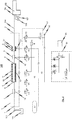
- FIGS. 4 and 5 schematically powder spray coating apparatuses 100 are shown in which embodiments of the powder sealant pump 1 according to the invention for conveying coating powder from a first powder reservoir 101 to a downstream of the powder sealant pump 1 arranged powder spray coating gun 102 are used.
- the powder spray coating gun 102 instead of the powder spray coating gun 102, another device for spraying coating powder onto an object to be coated or a second powder reservoir can also be used.
- the exemplary embodiment of powder sealant pump 1 according to the invention used therein has a powder inlet 2, which is connected or connectable to first powder reservoir 101 by means of a powder line 103, in particular by means of an intake pipe or the like.
- a powder outlet 3 is provided, which is connected or connectable by means of a powder line 104, in particular by means of a powder hose, to a coating powder inlet 105 of the powder spray coating gun 102.
- both the powder inlet 2 and the powder outlet 3 of the powder sealant pump 1 are each formed as a hose connection piece to which the corresponding powder line 103 and 104 attachable and can be fixed with a hose clamp.
- the powder inlet 2 and the powder outlet 3 come into question.
- the powder sealant pump 1 is characterized in that it is designed as a single-chamber powder seal pump, wherein for conveying coating powder from the first powder reservoir 101 to the powder spray coating gun 102 or to another device for spray coating of objects or to another powder reservoir only a single powder conveying chamber 4 is provided.
- the (only) powder delivery chamber 4 has at a first end region a powder inlet 5 which points in the direction of the powder inlet 2 of the powder sealant flow pump 1. Furthermore, the powder delivery chamber 4 has a powder outlet 6 pointing in the direction of the powder outlet 3 of the powder sealant flow pump 1.
- a powder inlet valve 7 is disposed immediately adjacent the powder inlet 5 of the powder delivery chamber 4, in such a way that this powder inlet valve 7 lies between the powder inlet 5 of the powder delivery chamber 4 and the powder inlet 2 of the powder sealant pump 1.
- a powder outlet valve 8 is arranged immediately adjacent to the powder outlet 6 of the powder conveying chamber 4.
- the powder outlet valve 8 is not disposed directly between the powder outlet 6 of the powder delivery chamber and the powder outlet 3 of the powder sealant flow pump 1; Rather, between the powder outlet 8 and the powder outlet 3 of the powder seal current pump 1, an additional compressed air inlet device 9 is arranged. As will be described in more detail below, this additional compressed air inlet device 9 is used for supplying additional transport compressed air as needed into the powder path between the powder outlet valve 8 and the powder outlet 3 of the powder sealant pump 1.
- auxiliary compressed air inlet device 9 between the powder outlet valve 8 and the powder outlet 3 of the powder seal current pump 1.
- the effects achievable with the additional compressed air inlet device 9, which are described in more detail below, can also be realized when the additional compressed air inlet device 9 is arranged behind the powder outlet 3 of the powder seal current pump 1.
- the powder inlet 2 of the powder sealant pump 1, the powder inlet valve 7, the powder inlet 5 of the powder delivery chamber 4, the powder delivery chamber 4, the powder outlet 6 of the powder delivery chamber 4, the auxiliary compressed air inlet device 9 and the powder outlet 3 of the powder seal flow pump 1 lie along a common longitudinal axis
- the powder inlet 2 of the powder sealant flow pump 1 is provided at the opposite end of the powder outlet 3 of the powder sealant flow pump 1.
- the powder feed chamber 4 is formed between its powder inlet 5 and its powder outlet 6 through the cylindrical wall of a tubular filter 10, which is permeable to air, but not for coating powder and may for example consist of sintered material.
- the filter 10 designed as a filter tube is surrounded by an intermediate chamber 11, which is bounded on its outer side by a housing 12 of the powder delivery chamber 4.
- the powder feed chamber 4 is alternately supplied with transport compressed air from a compressed air supply line 50 or with vacuum or vacuum of a vacuum source 52 acted upon.
- the vacuum source 52 an injector 55, which injector compressed air from a compressed air supply line 54 and a compressed air source 58, for example via a pressure regulator 53 and another control valve V2, are supplied.
- the powder outlet valve 8 arranged at the powder outlet 6 of the powder feed chamber 4 is closed and that between the powder inlet 2 of the powder seal flow pump 1 and the powder inlet 5 of the powder conveying chamber 4 arranged powder inlet valve 7 is opened. Simultaneously with the actuation of the powder outlet valve 8 and the powder inlet valve 7 or immediately thereafter, the powder feed chamber 4 is connected to the vacuum source 52 via the control valve V1 and the associated air exchange opening 13 so that a vacuum is applied in the powder feed chamber 4 and coating powder from the first powder reservoir 101 can be sucked.
- the powder inlet valve 7 is closed and the powder outlet valve 8 is opened, while the control valve V1 a fluid connection of the air exchange opening 13 with the compressed air supply line 50, so that the coating powder portion previously sucked into the powder feed chamber 4 during the suction phase is discharged through the open powder discharge valve 8 by means of the conveying compressed air supplied through the air exchange port 13.
- pump cycle is understood to mean a cycle consisting of a suction phase and an ejection phase.
- valves are preferably designed in each case as a pinch valve, although other valve types come into question in principle.
- the powder inlet and powder outlet valves 7, 8 designed as pinch valve in the exemplary embodiment shown in the drawings each have a flexible elastic hose 14.1, 14.2, which serves as a valve channel.
- the flexible elastic hose 14.1, 14.2 can be crimped together to close the corresponding valve (powder inlet valve 7, powder outlet valve 8) by means of actuating compressed air in a pressure chamber 15.1, 15.2 surrounding the flexible elastic tube 14.1, 14.2.
- an air exchange opening 16 is provided in each pressure chamber 15.1, 15.2 in each case, which is connected to a corresponding control valve V3, V4.
- the control valves V3, V4 serve, alternately, the pressure chambers 15.1, 15.2 of the two powder inlet valves, each designed as a pinch valve. or powder outlet valves 7, 8 to pressurize with pressure from a compressed air supply line 56.
- the compressed air supply line 56 is connected to a pressure accumulator 57, wherein the accumulator 57 in turn is connected to a compressed air source 58.
- the compressed air supply line 56 is connected directly to the compressed air source 58 (i.e., without the interposition of a pressure accumulator 57).
- the flexible elastic hose 14.1, 14.2 of the powder inlet valve 7 or powder outlet valve 8 designed as a pinch valve preferably has such an elasticity or internal stress that it automatically stretches again after the pressure of the actuating compressed air in the pressure chamber 15.1, 15.2 disappears, thereby opening the corresponding valve channel.
- a negative pressure is applied via the corresponding air exchange openings 16.
- the powder sealant pump 1 is structurally constructed and constructed so that the pumping frequency achievable with the powder sealant pump 1 can be increased as compared with the pumping frequency achievable with conventional multi-chamber powder sealant pumps.
- a material block 60 is used, in which in advantageous realizations of the powder sealant pump 1 according to the invention the powder inlet valve 7 required for conveying coating powder and also the powder outlet valve 8 required for conveying coating powder, including those for actuating these valves 7, 8 required control valves V3, V4 may be attached (not explicitly shown in the drawings).
- Both the powder inlet valve 7 and the powder outlet valve 8 and the control valves V3, V4 required for the actuation thereof are preferably connected to channels formed in the material block 60 (not shown in the figures).
- the corresponding control valves V1, V3 and V4 and the powder inlet and powder outlet valves 7, 8 are arranged as close as possible to the components of the powder sealant pump 1 to be switched, it is avoided that in the corresponding pressure lines are pneumatically actuated valves 7, 8 or in the corresponding pressure line to the air exchange opening 13 of the powder delivery chamber 4 large volumes present, which must be selectively evacuated during alternate operation of the powder seal pump 1 or filled with compressed air. This can prevent that excessive reaction delay times occur, which would ultimately limit the frequency with which the powder sealant pump 1 can promote coating powder.
- the Pulverdichtstromstromstrompumpe 1 advantageously has a modular structure in which the components "powder inlet 2 of the powder sealant pump 1", “powder inlet valve 7", “powder delivery chamber 4", “Pulverauslassventil 8" and “additional compressed air inlet device 9" are each formed as a modular component together with "powder outlet 3 of the powder sealant pump 1".
- the module constituting the powder inlet 2 of the powder sealant flow pump 1 is indicated by the reference numeral "61" in the drawings, while the module 62 disposed downstream thereof constitutes the powder inlet valve 7.
- the modules 63 and 64 form the powder feed chamber 4 and the powder outlet valve 8, while the module 65 forms the combination of the auxiliary compressed air inlet device 9 and the powder outlet 3 of the powder seal current pump 1.
- the individual modules 61, 62, 63, 64 and 65 are aligned axially with respect to the common longitudinal axis L and mounted one behind the other on the block of material 60.
- the modular design of the powder sealant pump 1 simplifies the maintenance of the pump considerably, since if necessary, for example in the case of a defect or for the purpose of maintenance and / or cleaning, the individual modules 61, 62, 63, 64 and 65 of the pump with the corresponding components can be easily and especially quickly replaced.
- the susceptibility of the pump to failure is greater than that of conventional multi-chamber powder seal pumps in which at least four powder valves and one correspondingly Higher number of control valves for control of the powder valves must be used, significantly reduced.
- the number of wear parts in the powder seal current pump 1 according to the invention is reduced to a minimum, so that a correction of the settings of the powder seal current pump 1 due to wear parts much rarer to perform and a high reproducibility of the settings of the pump is guaranteed.
- the single chamber design used in the powder seal current pump 1 according to the invention allows a particularly compact design of the pump.
- powder delivery of up to 400 g of coating powder per minute can be achieved (width of the pump: 40 mm).
- a filter tube 17 which has a circumference of at least 180 ° (in the illustrated embodiments, a circumference of 360 °) and at least a partial length of the corresponding powder path, a channel wall inner surface to at least 180 ° (in the embodiments shown in the drawings, a channel wall inner surface to 360 °) forms the Pulverwegiscuses.
- the auxiliary compressed air inlet device 9 has a filter tube 17 which surrounds the corresponding powder path for at least a partial length of 360 ° so that the powder ejected from the powder feed chamber 4 of the powder seal current pump 1 during a powder ejection phase Powder portion through the filter tube 17 formed by the filter tube 17 can flow homogeneously.
- compressed air chamber 19 surrounds the filter tube 17 on its outer circumference.
- the compressed air chamber 19 designed here as a compressed air ring chamber is surrounded at its radially inner periphery by the filter tube 17 and at a distance from the filter tube 17 at its radially outer periphery by a housing 20.
- an air exchange opening 21 is introduced, via which, if necessary, compressed air can flow from a compressed air line 59 via a control valve V5 in the compressed air chamber 19 and from there through the filter tube 17 into the filter tube channel 18.
- the compressed air chamber 19 and the filter tube channel 18 formed by the filter tube 17 must be designed to be correspondingly larger in volume.
- the filter tube 17 of the additional compressed air inlet device 9 of microporous material is such that it is permeable to air, but not for coating powder.
- the filter tube 17 is preferably made of a sintered body, for example of metal or plastic, or of a metal or plastic-containing material mixture. Furthermore, it may consist of a different material and / or be formed by a filter membrane.
- the filter pores of the filter tube 17 are preferably designed such that compressed air is passed into the powder path via a powder path region which is large in the circumferential direction as well as in the longitudinal direction of the powder path.
- These micropores of the powder tube 17 may be inclined radially or in the axial direction to the powder path and / or open tangentially to Pulverweghold from the filter tube 17 into the filter tube channel 18 and direct the compressed air accordingly. Due to the large surface of the filter tube 17 on its inner circumference can be homogenized with a small amount of compressed air, the axial powder distribution in the filter tube channel 18 and thus also in the powder path downstream of the powder outlet 3 of the powder seal 1. As a result, pulsations of the powder flow in the powder path can be avoided or at least reduced. Furthermore, a homogenization of the powder density in the longitudinal direction and over the cross section of the powder path can be achieved.
- the transport compressed air quantity per unit time fed into the powder path can be kept so small that it has no or only a small influence on the flow velocity of the coating powder in the flow path.
- the compressed air additionally fed with the additional compressed air inlet device 9 into the powder path of the powder sealant pump 1 can flow in the form of jets or in the form of small air bubbles from the filter tube 17 into the filter tube channel 18, depending on the type of filter pores and the air pressure.
- the filter tube 17 of the auxiliary compressed air inlet device 9 should extend around the powder path for at least 180 ° of the powder path circumference, preferably over the full 360 ° of the powder path circumference.
- the filter tube 17 of the auxiliary compressed air inlet device 9 is preferably a rigid body. But it could also be a flexible body.
- the additional compressed air of the additional compressed air inlet device 9 is pulsed at a pulse frequency which is equal to or preferably greater than the frequency of the powder delivery chamber 4, with which the powder delivery chamber 4 delivers powder portions.
- a pulsating compressed air source or a compressed air pulse generator for the additional compressed air inlet device 9 can be provided.
- a control device 90 is provided, which is designed such that the pulse frequency the additional compressed air inlet device 9 supplied additional compressed air is adjustable in dependence on the powder delivery frequency of the powder delivery chamber 4 in at least one of the following ways: for example, manually adjustable and / or is preferably automatically controlled or preferably controlled.
- the additional compressed air pulse frequency can be increased with increasing Pulverabgabefrequenz and reduced with decreasing Pulverabgabefrequenz.
- control device 90 may advantageously be designed such that the additional compressed air quantity flowing through the additional compressed air inlet device 9 per unit time can be set in at least one of the following ways depending on the delivered powder quantity: for example manually adjustable is and / or preferably automatically controllable or preferably controllable.
- the control device 90 of the powder spray coating device 100 can be designed for the mentioned setting of the additional compressed air pulse frequency or for the said setting of the additional compressed air quantity, or for both settings.
- the controller 90 may include all controls, or two or more controllers may be provided. If it is desired to set the additional compressed air pulse frequency or the additional compressed air flow rate manually, a manual adjusting element can be provided for each of these.
- the powder inlet valve 7 and the powder outlet valve 8 of the powder seal current pump 1 according to the invention are each preferably designed as pinch valves, since less coating powder can be deposited in pinch valves than in other valve types, and because powder deposits due to the air flow in let them clean easily.
- Pinch valves are controllable by means of compressed air or by means of negative pressure valves. In principle, however, other controllable valves are used.
- automatic valves such as ball valves or flap valves, which are controlled by the differential pressure between the valve inlet side and the Ventilauslassseite and thus automatically by the pressure and negative pressure, which prevails in the powder feed chamber 4.
- control device 90 To control the operation of the powder seal current pump 1, the already mentioned control device 90 is used, which in Fig. 3 is indicated schematically.
- the control device 90 is designed to suitably control the individual controllable components of the powder seal current pump 1, in particular the control valves V1, V2, V3, V4 and V5, and to coordinate their actuation.
- FIGS. 4 and 5 schematically illustrated embodiments of the powder spray coating device 100 according to the invention is still another control valve V6 provided, via which in a cleaning cycle of the powder sealant pump 1, the powder feed chamber 4 can be acted upon by high pressure.
- the control device 90 is preferably designed such that it opens the control valve V4 in preparation for the suction phase of the powder delivery chamber 4, so that the compressed air provided in the pressure accumulator 57 or by the compressed air source 58 via the compressed air supply line 56 and the air exchange opening 16 in the pressure chamber 15.2 of as a pinch valve formed powder outlet valve 8 is passed.
- the flexible elastic tube 14.2 of the powder discharge valve 8 formed as the pinch valve is squeezed, as a result of which the powder path provided by the flexible elastic tube 14.2 is closed by the powder discharge valve 8.
- the air exchange opening 13 provided in the housing 12 of the powder delivery chamber 4 is fluidly connected to the vacuum source 52 by means of the control means 90 to generate a negative pressure inside the powder delivery chamber 4, so that coating powder through the powder inlet 2 of the powder seal 1 and the (opened) powder inlet valve 7 and the powder inlet 5 of the powder feed chamber 4 can be sucked into the powder feed chamber 4.
- the predetermined delay time is preferably in the range between 0 ms and 50 ms for a delivery cycle of the powder delivery chamber 4 of approximately 200 ms.
- control valve V3 is fluidly connected to the compressed air supply line 56, as a result of which an overpressure is applied in the pressure chamber 15.1 of the pinch valve formed powder inlet valve 7, which causes a squeezing of the flexible elastic tube 14.1 designed as a pinch valve Pulereinlassventils 7.
- the powder intake valve 7 is closed.
- the control valve V4 switches the air exchange opening 17 of the pressure chamber 15.2 of the powder outlet valve 8 designed as a pinch valve depressurized or vents the pressure chamber 15.2. Due to the elasticity of the hose 14.2 of the powder outlet valve 8 designed as a pinch valve, this then passes directly into its open state.
- control valve V1 is switched such that the air exchange opening 13 formed in the housing 12 of the powder delivery chamber 4 is fluidly connected to the compressed air source 58.
- the compressed air then flows via the compressed air supply line 50, the control valve V1, the intermediate chamber 11 and the filter element 10 into the powder feed chamber 4 and drives the previously sucked powder portion from the powder outlet 6 of the powder feed chamber 4.
- the powder portion is transported further through the opened powder outlet valve 8, the filter tube channel 18 of the auxiliary compressed air inlet device 9 and the powder outlet 3 of the powder seal current pump 1.
- the control device 90 is designed, in particular, to feed pulse-type additional transport compressed air into the powder path between the powder outlet valve 8 and the powder outlet 3 of the powder seal current pump 1 via the additional compressed air inlet device 9.
- additional transport compressed air is always fed during the entire or during a predetermined or predeterminable period of the suction phase of the powder feed chamber 4, in order to effectively pulsations in to avoid or minimize the powder flow discharged from the powder seal current pump 1.
- the controller 90 is configured to always communicate the air exchange port 21 of the compressed air chamber 19 of the auxiliary compressed air intake device 9 with the compressed air source 58 whenever the powder discharge valve 8 is closed.
- the individual compressed air supply lines 50, 54, 56 and 59 run into a control unit 91 in which the compressed air supply of the individual components of the powder spray coating device 100 is coordinated and controlled.
- the per unit time of the powder spray coating gun 102 via the compressed air input 106 of the powder spray coating gun 102 amount of additional compressed air, which serves to atomize, for shaping and / or otherwise influencing the spray powder to be sprayed by the powder spray coating gun 102, and / or the amount of electrode scavenging air supplied per unit time of the powder spray coating gun 102 via the compressed air inlet 107 of the powder spray coating gun 102.
- auxiliary compressed air inlet device 9 used filter tube 17 and the filter 10 used in the powder conveying chamber 4 to understand. In this way, it is ensured that the transport compressed air introduced into the powder feed chamber 4 during the discharge phase experiences the same pneumatic resistance as the additional compressed air which is fed into the powder path downstream of the powder outlet valve 8 via the auxiliary compressed air inlet device 9 during the powder suction phase.
- the solution according to the invention is not limited to a powder sealant pump 1, which has a powder inlet 2 at a first end region and a powder outlet 3 at an opposite second end region, which in the illustrations according to FIGS FIGS. 1 to 5 is shown. Rather, the solution according to the invention is also suitable for embodiments in which - as in the FIGS. 6 and 7 schematically illustrated - the only powder conveying chamber 4 of the powder sealant pump 1 at one end region has a powder passage 30 which serves both as a powder inlet and as a powder outlet for the powder feed chamber 4. In the in the FIGS.
- the powder inlet 2 of the powder seal stream pump 1 is fluidly connected to the powder passage 30 of the powder conveying chamber 4 via the powder inlet valve 7 and the powder outlet 3 of the powder seal stream pump 1 via the powder outlet valve 8.
- a distributor 31 is used, in the in the FIGS. 6 and 7 illustrated embodiments is designed as a Y-piece.
- this manifold 31 of the powder passage 30 of the powder feed chamber 4 with the powder inlet valve 7 on the one hand and the powder outlet valve 8 on the other hand fluidly connected.
- Fig. 7 schematically illustrated embodiment of the powder sealant pump 1 differs from the in Fig. 6 shown embodiment in that the auxiliary compressed air inlet device 9 is identical to the transport compressed-air inlet device of the powder feed chamber 4 designed to equate the occurring during the introduction of the transporting compressed air and the introduction of the additional compressed air pneumatic resistors.
- FIGS. 7 and 8 illustrated embodiments correspond to the components of the embodiments according to FIGS FIGS. 1 to 5 , in which connection reference is made to the previous statements.
- the invention is not limited to the embodiments of the powder sealant pump according to the invention shown in the drawings, but results from a synopsis of all features disclosed herein.
Applications Claiming Priority (3)
| Application Number | Priority Date | Filing Date | Title |
|---|---|---|---|
| DE102013205895.0A DE102013205895A1 (de) | 2013-04-03 | 2013-04-03 | Pulverdichtstrompumpe zum Fördern von Beschichtungspulver sowie entsprechendes Verfahren |
| DE102013211536.9A DE102013211536A1 (de) | 2013-06-19 | 2013-06-19 | Pulverfördervorrichtung insbesondere für Beschichtungspulver und Verfahren zum Betreiben einer Pulverfördervorrichtung |
| PCT/EP2014/055446 WO2014161718A1 (de) | 2013-04-03 | 2014-03-18 | Pulverdichtstrompumpe und entsprechendes betriebsverfahren |
Publications (2)
| Publication Number | Publication Date |
|---|---|
| EP2981365A1 EP2981365A1 (de) | 2016-02-10 |
| EP2981365B1 true EP2981365B1 (de) | 2018-05-09 |
Family
ID=50336320
Family Applications (2)
| Application Number | Title | Priority Date | Filing Date |
|---|---|---|---|
| EP14711243.7A Active EP2981365B1 (de) | 2013-04-03 | 2014-03-18 | Pulverdichtstrompumpe und entsprechendes betriebsverfahren |
| EP14711242.9A Active EP2981364B1 (de) | 2013-04-03 | 2014-03-18 | Pulverfördervorrichtung und zugehöriges betriebsverfahren |
Family Applications After (1)
| Application Number | Title | Priority Date | Filing Date |
|---|---|---|---|
| EP14711242.9A Active EP2981364B1 (de) | 2013-04-03 | 2014-03-18 | Pulverfördervorrichtung und zugehöriges betriebsverfahren |
Country Status (6)
| Country | Link |
|---|---|
| US (3) | US9745148B2 (zh) |
| EP (2) | EP2981365B1 (zh) |
| CN (2) | CN105142799B (zh) |
| BR (2) | BR112015024418B8 (zh) |
| TW (2) | TW201446338A (zh) |
| WO (2) | WO2014161718A1 (zh) |
Families Citing this family (20)
| Publication number | Priority date | Publication date | Assignee | Title |
|---|---|---|---|---|
| DE102013205362A1 (de) | 2013-03-26 | 2014-10-02 | Gema Switzerland Gmbh | Sprühbeschichtungspistole zur Sprühbeschichtung von Gegenständen mit Beschichtungspulver |
| WO2014161718A1 (de) | 2013-04-03 | 2014-10-09 | Gema Switzerland Gmbh | Pulverdichtstrompumpe und entsprechendes betriebsverfahren |
| US9574714B2 (en) * | 2013-07-29 | 2017-02-21 | Nordson Corporation | Adhesive melter and method having predictive maintenance for exhaust air filter |
| EP3495292B1 (en) | 2014-05-15 | 2020-10-07 | Nordson Corporation | Dense phase pump diagnostics |
| DE102014223307B4 (de) | 2014-11-14 | 2020-07-16 | Gema Switzerland Gmbh | Pulverbehälter zur Versorgung einer Sprühbeschichtungsanlage mit Beschichtungspulver |
| US9650206B2 (en) * | 2015-07-24 | 2017-05-16 | Dynamic Aur Inc. | Conveying systems |
| IT201600074328A1 (it) * | 2016-07-15 | 2018-01-15 | Verne Tech S R L | Pompa per polveri ad alta densità. |
| EP3583322A4 (en) * | 2017-02-15 | 2020-12-16 | Nikon Corporation | DOUBLE VALVE FLUID ACTUATOR ASSEMBLY |
| DE102017103487A1 (de) * | 2017-02-21 | 2018-08-23 | Gema Switzerland Gmbh | Pulverdichtstrompumpe |
| US10760933B2 (en) * | 2017-04-27 | 2020-09-01 | Oerlikon Metco (Us) Inc. | Method for detecting and diagnosing powder flow stability |
| CN107790318B (zh) * | 2017-12-08 | 2023-09-08 | 山东大学 | 一种渐变涂层的双路送粉热喷涂装置及工作方法 |
| PL3552714T3 (pl) * | 2018-04-12 | 2021-08-30 | Wagner International Ag | Przenośnik proszku do transportowania proszku powlekającego, sposób wykonania przenośnika proszku i centrum proszku z przenośnikiem proszku do zasilania instalacji do powlekania proszkowego |
| DE102019101930A1 (de) * | 2018-12-27 | 2020-07-02 | Gema Switzerland Gmbh | Pulverabgabevorrichtung mit einer Pulverdünnstrompumpe |
| PL3685924T3 (pl) * | 2019-01-25 | 2022-04-19 | Wagner International Ag | Urządzenie przenoszące proszek do proszku powlekającego i instalacja do powlekania proszkowego z urządzeniem przenoszącym proszek |
| CN112718281B (zh) * | 2019-10-14 | 2022-07-19 | 上海中国弹簧制造有限公司 | 弹簧静电喷粉系统 |
| JP2021105392A (ja) * | 2019-12-27 | 2021-07-26 | 学校法人 中央大学 | ポンプユニット及びポンプ並びに搬送物の特性検出方法 |
| CN113599915B (zh) * | 2021-08-05 | 2022-11-11 | 青海盐湖工业股份有限公司 | 一种粉尘混合气体处理系统 |
| EP4141390B1 (de) | 2021-08-31 | 2024-03-20 | Wagner International AG | Messvorrichtung zum messen eines mit druckgas erzeugbaren beschichtungspulver-massenstroms in einer pulverleitung und fördervorrichtung für beschichtungspulver |
| CN113716347B (zh) * | 2021-08-31 | 2023-07-28 | 成都瑞柯林工程技术有限公司 | 用于颗粒物气力输送的系统、装置、方法及控制装置 |
| CN114166466B (zh) * | 2021-12-03 | 2022-11-25 | 上海交通大学 | 一种颗粒回收装置、水力提升试验系统及颗粒回收方法 |
Citations (1)
| Publication number | Priority date | Publication date | Assignee | Title |
|---|---|---|---|---|
| DE10353968A1 (de) * | 2003-11-19 | 2005-07-07 | Itw Gema Ag | Beschichtungspulver-Fördervorrichtung und -Förderverfahren |
Family Cites Families (53)
| Publication number | Priority date | Publication date | Assignee | Title |
|---|---|---|---|---|
| US4662799A (en) * | 1985-05-17 | 1987-05-05 | Fuller Company | Apparatus and process for pneumatically conveying particulate material |
| US4893966A (en) * | 1987-07-07 | 1990-01-16 | Franz Roehl | Lock apparatus for introducing dry granular materials into a pneumatic conveying conduit and spray gun for such materials |
| US4900199A (en) * | 1988-10-21 | 1990-02-13 | The Perkin-Elmer Corporation | High pressure power feed system |
| US5344077A (en) | 1992-09-14 | 1994-09-06 | Terry Roy D A | Apparatus for delivering compressed particulate solid fire fighting agent |
| DE4325044C2 (de) * | 1993-07-26 | 2002-07-18 | Itw Gema Ag | Pulverfördervorrichtung, insbesondere für Beschichtungspulver |
| US5711489A (en) | 1994-08-18 | 1998-01-27 | Nihon Parkerizing Co., Ltd. | Electrostatic powder coating method and apparatus |
| DE19611533B4 (de) | 1996-03-23 | 2005-11-03 | Itw Gema Ag | Vorrichtung zur Pulverbeschichtung |
| FR2771721B1 (fr) * | 1997-12-02 | 2000-02-18 | Lucien Vidal | Dispositif pour transporter pneumatiquement un materiau tel que du beton |
| SE9800033L (sv) * | 1998-01-09 | 1999-05-31 | Paer Wellmar | Förfarande och anläggning för pneumatisk transport av fasta partiklar |
| DE19842773A1 (de) * | 1998-09-18 | 2000-04-06 | Motan Fuller Verfahrenstechnik | Überström-Ventil mit längenunabhängigem Einbau |
| DE19959473A1 (de) | 1999-12-10 | 2001-06-13 | Frederic Dietrich | Vorrichtung und Verfahren zum pneumatischen Fördern pulverförmiger Stoffe sowie Verwendung der Vorrichtung |
| US6447216B1 (en) | 2000-08-17 | 2002-09-10 | Xerox Corporation | Fluid pumping system for particulate material |
| JP2002192058A (ja) * | 2000-12-26 | 2002-07-10 | Aisin Seiki Co Ltd | 粉体塗布剤供給装置 |
| DE10145448A1 (de) * | 2001-09-14 | 2003-05-22 | Bayerische Motoren Werke Ag | Vorrichtung zum Fördern von Pulver und Verfahren zu deren Betrieb |
| DE10147858A1 (de) | 2001-09-27 | 2003-04-30 | Itw Gema Ag | Spritzbeschichtungsvorrichtung |
| US6719500B2 (en) * | 2002-08-20 | 2004-04-13 | The Young Industries, Inc. | System for pneumatically conveying bulk particulate materials |
| DE10238946A1 (de) * | 2002-08-24 | 2004-03-04 | Mann + Hummel Protec Gmbh | Fördervorrichtung für schüttfähiges Gut |
| US7150585B2 (en) * | 2002-10-14 | 2006-12-19 | Nordson Corporation | Process and equipment for the conveyance of powdered material |
| DE10300280A1 (de) * | 2003-01-08 | 2004-07-22 | Itw Gema Ag | Pumpeneinrichtung für Pulver, Verfahren hierfür und Pulverbeschichtungseinrichtung |
| WO2004065911A2 (en) * | 2003-01-16 | 2004-08-05 | North Carolina State University | Apparatus and method for controlling flow of process materials |
| ITMI20031419A1 (it) | 2003-07-11 | 2005-01-12 | Studio A Z Di Giancarlo Simontacchi | Dispositivo per il trasporto di polveri attraverso tubazioni |
| US7793869B2 (en) | 2003-08-18 | 2010-09-14 | Nordson Corporation | Particulate material applicator and pump |
| US20050158187A1 (en) * | 2003-11-24 | 2005-07-21 | Nordson Corporation | Dense phase pump for dry particulate material |
| DE102004007967A1 (de) * | 2004-02-18 | 2005-09-08 | Dürr Systems GmbH | Pulverförderpumpe und zugehöriges Betriebsverfahren |
| US7241080B2 (en) * | 2004-03-22 | 2007-07-10 | Durr Industries, Inc. | Pump for transferring particulate material |
| DE102004052949A1 (de) * | 2004-10-29 | 2006-05-04 | Nordson Corp., Westlake | Verfahren und Vorrichtung zur Überwachung von Strömungsverhältnissen in einem Leitungsstrang |
| NZ560387A (en) * | 2005-01-18 | 2009-09-25 | Apla Tech Inc | Material management system for continuous flow of drywall compound |
| DE102005003620A1 (de) * | 2005-01-26 | 2006-08-03 | Lanxess Deutschland Gmbh | Verfahren und Vorrichtung zur pneumatischen Förderung von schwerfließendem Schüttgut |
| DE102005006522B3 (de) * | 2005-02-11 | 2006-08-03 | J. Wagner Ag | Vorrichtung zum Fördern von Beschichtungspulver und Verfahren zum Fördern von Pulver mit der Fördervorrichtung |
| DE202006015697U1 (de) | 2005-05-31 | 2007-03-08 | Nordson Corporation, Westlake | Verbesserter Applikator für Teilchenmaterial und Pumpe |
| EP1752399B1 (de) | 2005-08-12 | 2009-01-21 | J. Wagner AG | Vorrichtung und Methode zum Fördern von Pulver |
| US7731456B2 (en) * | 2005-10-07 | 2010-06-08 | Nordson Corporation | Dense phase pump with open loop control |
| DE102006019643B4 (de) | 2006-04-25 | 2008-09-25 | Reinhold Gregarek | Vorrichtung zur pneumatischen, tribostatischen Pulverbeschichtung von Werkstücken |
| DE102007005313A1 (de) * | 2007-02-02 | 2008-08-07 | Itw Gema Ag | Beschichtungspulver-Fördervorrichtung |
| EP1958899B1 (de) * | 2007-02-16 | 2013-08-21 | J. Wagner AG | Vorrichtung zum Fördern von Fluid |
| EP2279797B1 (en) | 2007-05-09 | 2016-01-13 | Nordson Corporation | Nozzle with internal filter |
| WO2008150790A1 (en) | 2007-05-29 | 2008-12-11 | Nordson Corporation | High density powder coating pump and nozzle for producing a narrow, dense spray pattern |
| DE102007041551A1 (de) * | 2007-08-31 | 2009-03-05 | Itw Gema Gmbh | Pulversprühbeschichtungsvorrichtung und Beschichtungspulver-Fördervorrichtung dafür |
| DE102007045330A1 (de) * | 2007-09-22 | 2009-04-02 | Itw Gema Gmbh | Beschichtungspulver-Förderverfahren, Beschichtungspulver-Fördervorrichtung und elektrostatische Pulversprühbeschichtungsvorrichtung |
| DE102007046738A1 (de) | 2007-09-28 | 2009-04-02 | Itw Gema Gmbh | Pulversprühbeschichtungsverfahren und -vorrichtung |
| DE102007049219A1 (de) * | 2007-10-13 | 2009-04-16 | Itw Gema Gmbh | Pulverfördervorrichtung für Pulversprühbeschichtungsvorrichtungen |
| US9731914B2 (en) * | 2008-11-06 | 2017-08-15 | Michael J. Rasner | Pneumatic convey system with constant velocity pickup |
| US8790048B2 (en) * | 2008-11-14 | 2014-07-29 | J-Power Entech, Inc. | Lock hopper |
| DE102009016095A1 (de) * | 2009-04-03 | 2010-10-14 | Impellis GmbH & Co. KG Oberflächentechnik | Förderer für ein Pulver-/Gasgemisch |
| US20130011209A1 (en) * | 2010-02-07 | 2013-01-10 | Doig Ian D | Pipeline Conveyor Systems |
| DE102011004035A1 (de) * | 2011-02-14 | 2012-08-16 | Illinois Tool Works Inc. | Pulverpumpe zum Fördern von Beschichtungspulver |
| US9027506B2 (en) * | 2011-05-02 | 2015-05-12 | Nordson Corporation | Dense phase powder coating system for containers |
| CN102530562A (zh) * | 2012-02-03 | 2012-07-04 | 南车长江车辆有限公司 | 一种粉粒物料流态化输送管 |
| DE202013011934U1 (de) | 2012-04-13 | 2014-11-27 | Nordson Corporation | Pulverpistole, die zum Zuführen von einer Venturi- oder Dichtstrompumpe konfigurierbar ist |
| US9085065B2 (en) * | 2013-02-28 | 2015-07-21 | Comco Inc. | Particulate media conveying systems and apparatuses |
| DE102013205362A1 (de) | 2013-03-26 | 2014-10-02 | Gema Switzerland Gmbh | Sprühbeschichtungspistole zur Sprühbeschichtung von Gegenständen mit Beschichtungspulver |
| WO2014161718A1 (de) | 2013-04-03 | 2014-10-09 | Gema Switzerland Gmbh | Pulverdichtstrompumpe und entsprechendes betriebsverfahren |
| US8936416B2 (en) * | 2013-05-01 | 2015-01-20 | Crystal-Mark, Inc., A Swan Technologies Corporation | Fluidized particle abrasion device with precision control |
-
2014
- 2014-03-18 WO PCT/EP2014/055446 patent/WO2014161718A1/de active Application Filing
- 2014-03-18 EP EP14711243.7A patent/EP2981365B1/de active Active
- 2014-03-18 CN CN201480020210.5A patent/CN105142799B/zh active Active
- 2014-03-18 WO PCT/EP2014/055442 patent/WO2014161717A1/de active Application Filing
- 2014-03-18 BR BR112015024418A patent/BR112015024418B8/pt active IP Right Grant
- 2014-03-18 EP EP14711242.9A patent/EP2981364B1/de active Active
- 2014-03-18 BR BR112015025287-7A patent/BR112015025287B1/pt active IP Right Grant
- 2014-03-18 US US14/782,316 patent/US9745148B2/en active Active
- 2014-03-18 US US14/782,298 patent/US10112787B2/en active Active
- 2014-03-18 CN CN201480019566.7A patent/CN105121027B/zh active Active
- 2014-03-26 TW TW103111230A patent/TW201446338A/zh unknown
- 2014-03-26 TW TW103111228A patent/TW201501810A/zh unknown
-
2018
- 2018-09-24 US US16/140,275 patent/US10604360B2/en active Active
Patent Citations (1)
| Publication number | Priority date | Publication date | Assignee | Title |
|---|---|---|---|---|
| DE10353968A1 (de) * | 2003-11-19 | 2005-07-07 | Itw Gema Ag | Beschichtungspulver-Fördervorrichtung und -Förderverfahren |
Also Published As
| Publication number | Publication date |
|---|---|
| TW201446338A (zh) | 2014-12-16 |
| BR112015024418B8 (pt) | 2021-03-23 |
| CN105121027B (zh) | 2018-04-03 |
| TW201501810A (zh) | 2015-01-16 |
| BR112015025287B1 (pt) | 2021-01-05 |
| US20160052000A1 (en) | 2016-02-25 |
| US10112787B2 (en) | 2018-10-30 |
| EP2981364B1 (de) | 2018-05-30 |
| US10604360B2 (en) | 2020-03-31 |
| US9745148B2 (en) | 2017-08-29 |
| CN105142799A (zh) | 2015-12-09 |
| BR112015024418A2 (pt) | 2017-07-18 |
| CN105121027A (zh) | 2015-12-02 |
| US20160122138A1 (en) | 2016-05-05 |
| BR112015025287A2 (pt) | 2017-07-18 |
| WO2014161717A1 (de) | 2014-10-09 |
| BR112015024418B1 (pt) | 2021-02-23 |
| WO2014161718A1 (de) | 2014-10-09 |
| CN105142799B (zh) | 2017-12-05 |
| US20190023505A1 (en) | 2019-01-24 |
| EP2981364A1 (de) | 2016-02-10 |
| EP2981365A1 (de) | 2016-02-10 |
Similar Documents
| Publication | Publication Date | Title |
|---|---|---|
| EP2981365B1 (de) | Pulverdichtstrompumpe und entsprechendes betriebsverfahren | |
| EP3010645B1 (de) | Pulverfördervorrichtung für beschichtungspulver | |
| EP2279796A2 (de) | Verfarhen und Vorrichtung zum Fördern von pulverförmigem Material | |
| WO2003024612A1 (de) | Vorrichtung zum fördern von pulver und verfahren zu deren betrieb | |
| EP3585522B1 (de) | Pulverdichtstrompumpe | |
| DE202007018809U1 (de) | Pulversprühbeschichtungsvorrichtung und Beschichtungspulver-Fördervorrichtung dafür | |
| EP1752399B1 (de) | Vorrichtung und Methode zum Fördern von Pulver | |
| DE10353968A1 (de) | Beschichtungspulver-Fördervorrichtung und -Förderverfahren | |
| DE102010039473A1 (de) | Pulverversorgungsvorrichtung für eine Pulverbeschichtungsanlage | |
| EP3177406B1 (de) | Pulverabgabevorrichtung und pulverbeschichtungsanlage zum pulversprühbeschichten von gegenständen | |
| DE102007045330A1 (de) | Beschichtungspulver-Förderverfahren, Beschichtungspulver-Fördervorrichtung und elektrostatische Pulversprühbeschichtungsvorrichtung | |
| DE102013205895A1 (de) | Pulverdichtstrompumpe zum Fördern von Beschichtungspulver sowie entsprechendes Verfahren | |
| EP3302819B1 (de) | Verfahren zum betreiben einer pulverdichtstrompumpe sowie pulverdichtstrompumpe | |
| WO2023280939A1 (de) | Pulverförderkammer für eine pulverdichtstrompumpe sowie pulverdichtstrompumpe mit einer pulverförderkammer | |
| DE102007048520A1 (de) | Sprühbeschichtungspulver-Fördervorrichtung und Pulversprühbeschichtungsvorrichtung | |
| DE19613967A1 (de) | Vorrichtung zur Sprühbeschichtung | |
| DE102013211536A1 (de) | Pulverfördervorrichtung insbesondere für Beschichtungspulver und Verfahren zum Betreiben einer Pulverfördervorrichtung | |
| DE102006032184B4 (de) | Vorrichtung zum Fördern pulverförmiger fluidisierter Medien | |
| DE10261053A1 (de) | Verfahren und Vorrichtung zum Fördern von pulverförmigem Material | |
| DE10247829A1 (de) | Verfahren und Vorrichtung zum Fördern von pulverförmigem Material | |
| DE102004008495A1 (de) | Pulverförderpumpe | |
| WO2020136058A1 (de) | Pulverabgabevorrichtung mit einer pulverdünnstrompumpe | |
| DE202004013138U1 (de) | Luftverteiler für eine mit Druckluft betriebene Pulverfördereinheit einer Pulverbeschichtungsvorrichtung |
Legal Events
| Date | Code | Title | Description |
|---|---|---|---|
| PUAI | Public reference made under article 153(3) epc to a published international application that has entered the european phase |
Free format text: ORIGINAL CODE: 0009012 |
|
| 17P | Request for examination filed |
Effective date: 20150827 |
|
| AK | Designated contracting states |
Kind code of ref document: A1 Designated state(s): AL AT BE BG CH CY CZ DE DK EE ES FI FR GB GR HR HU IE IS IT LI LT LU LV MC MK MT NL NO PL PT RO RS SE SI SK SM TR |
|
| AX | Request for extension of the european patent |
Extension state: BA ME |
|
| DAX | Request for extension of the european patent (deleted) | ||
| 17Q | First examination report despatched |
Effective date: 20161019 |
|
| STAA | Information on the status of an ep patent application or granted ep patent |
Free format text: STATUS: EXAMINATION IS IN PROGRESS |
|
| GRAP | Despatch of communication of intention to grant a patent |
Free format text: ORIGINAL CODE: EPIDOSNIGR1 |
|
| STAA | Information on the status of an ep patent application or granted ep patent |
Free format text: STATUS: GRANT OF PATENT IS INTENDED |
|
| INTG | Intention to grant announced |
Effective date: 20171121 |
|
| GRAS | Grant fee paid |
Free format text: ORIGINAL CODE: EPIDOSNIGR3 |
|
| GRAA | (expected) grant |
Free format text: ORIGINAL CODE: 0009210 |
|
| STAA | Information on the status of an ep patent application or granted ep patent |
Free format text: STATUS: THE PATENT HAS BEEN GRANTED |
|
| AK | Designated contracting states |
Kind code of ref document: B1 Designated state(s): AL AT BE BG CH CY CZ DE DK EE ES FI FR GB GR HR HU IE IS IT LI LT LU LV MC MK MT NL NO PL PT RO RS SE SI SK SM TR |
|
| REG | Reference to a national code |
Ref country code: GB Ref legal event code: FG4D Free format text: NOT ENGLISH |
|
| REG | Reference to a national code |
Ref country code: CH Ref legal event code: EP Ref country code: AT Ref legal event code: REF Ref document number: 997097 Country of ref document: AT Kind code of ref document: T Effective date: 20180515 |
|
| REG | Reference to a national code |
Ref country code: DE Ref legal event code: R096 Ref document number: 502014008217 Country of ref document: DE Ref country code: IE Ref legal event code: FG4D Free format text: LANGUAGE OF EP DOCUMENT: GERMAN |
|
| REG | Reference to a national code |
Ref country code: DE Ref legal event code: R096 Ref document number: 502014008217 Country of ref document: DE |
|
| REG | Reference to a national code |
Ref country code: NL Ref legal event code: MP Effective date: 20180509 |
|
| REG | Reference to a national code |
Ref country code: LT Ref legal event code: MG4D |
|
| PG25 | Lapsed in a contracting state [announced via postgrant information from national office to epo] |
Ref country code: BG Free format text: LAPSE BECAUSE OF FAILURE TO SUBMIT A TRANSLATION OF THE DESCRIPTION OR TO PAY THE FEE WITHIN THE PRESCRIBED TIME-LIMIT Effective date: 20180809 Ref country code: NO Free format text: LAPSE BECAUSE OF FAILURE TO SUBMIT A TRANSLATION OF THE DESCRIPTION OR TO PAY THE FEE WITHIN THE PRESCRIBED TIME-LIMIT Effective date: 20180809 Ref country code: FI Free format text: LAPSE BECAUSE OF FAILURE TO SUBMIT A TRANSLATION OF THE DESCRIPTION OR TO PAY THE FEE WITHIN THE PRESCRIBED TIME-LIMIT Effective date: 20180509 Ref country code: LT Free format text: LAPSE BECAUSE OF FAILURE TO SUBMIT A TRANSLATION OF THE DESCRIPTION OR TO PAY THE FEE WITHIN THE PRESCRIBED TIME-LIMIT Effective date: 20180509 Ref country code: SE Free format text: LAPSE BECAUSE OF FAILURE TO SUBMIT A TRANSLATION OF THE DESCRIPTION OR TO PAY THE FEE WITHIN THE PRESCRIBED TIME-LIMIT Effective date: 20180509 Ref country code: ES Free format text: LAPSE BECAUSE OF FAILURE TO SUBMIT A TRANSLATION OF THE DESCRIPTION OR TO PAY THE FEE WITHIN THE PRESCRIBED TIME-LIMIT Effective date: 20180509 |
|
| PG25 | Lapsed in a contracting state [announced via postgrant information from national office to epo] |
Ref country code: NL Free format text: LAPSE BECAUSE OF FAILURE TO SUBMIT A TRANSLATION OF THE DESCRIPTION OR TO PAY THE FEE WITHIN THE PRESCRIBED TIME-LIMIT Effective date: 20180509 Ref country code: LV Free format text: LAPSE BECAUSE OF FAILURE TO SUBMIT A TRANSLATION OF THE DESCRIPTION OR TO PAY THE FEE WITHIN THE PRESCRIBED TIME-LIMIT Effective date: 20180509 Ref country code: RS Free format text: LAPSE BECAUSE OF FAILURE TO SUBMIT A TRANSLATION OF THE DESCRIPTION OR TO PAY THE FEE WITHIN THE PRESCRIBED TIME-LIMIT Effective date: 20180509 Ref country code: GR Free format text: LAPSE BECAUSE OF FAILURE TO SUBMIT A TRANSLATION OF THE DESCRIPTION OR TO PAY THE FEE WITHIN THE PRESCRIBED TIME-LIMIT Effective date: 20180810 Ref country code: HR Free format text: LAPSE BECAUSE OF FAILURE TO SUBMIT A TRANSLATION OF THE DESCRIPTION OR TO PAY THE FEE WITHIN THE PRESCRIBED TIME-LIMIT Effective date: 20180509 |
|
| PG25 | Lapsed in a contracting state [announced via postgrant information from national office to epo] |
Ref country code: PL Free format text: LAPSE BECAUSE OF FAILURE TO SUBMIT A TRANSLATION OF THE DESCRIPTION OR TO PAY THE FEE WITHIN THE PRESCRIBED TIME-LIMIT Effective date: 20180509 Ref country code: EE Free format text: LAPSE BECAUSE OF FAILURE TO SUBMIT A TRANSLATION OF THE DESCRIPTION OR TO PAY THE FEE WITHIN THE PRESCRIBED TIME-LIMIT Effective date: 20180509 Ref country code: SK Free format text: LAPSE BECAUSE OF FAILURE TO SUBMIT A TRANSLATION OF THE DESCRIPTION OR TO PAY THE FEE WITHIN THE PRESCRIBED TIME-LIMIT Effective date: 20180509 Ref country code: DK Free format text: LAPSE BECAUSE OF FAILURE TO SUBMIT A TRANSLATION OF THE DESCRIPTION OR TO PAY THE FEE WITHIN THE PRESCRIBED TIME-LIMIT Effective date: 20180509 Ref country code: RO Free format text: LAPSE BECAUSE OF FAILURE TO SUBMIT A TRANSLATION OF THE DESCRIPTION OR TO PAY THE FEE WITHIN THE PRESCRIBED TIME-LIMIT Effective date: 20180509 Ref country code: CZ Free format text: LAPSE BECAUSE OF FAILURE TO SUBMIT A TRANSLATION OF THE DESCRIPTION OR TO PAY THE FEE WITHIN THE PRESCRIBED TIME-LIMIT Effective date: 20180509 |
|
| REG | Reference to a national code |
Ref country code: DE Ref legal event code: R097 Ref document number: 502014008217 Country of ref document: DE |
|
| PG25 | Lapsed in a contracting state [announced via postgrant information from national office to epo] |
Ref country code: SM Free format text: LAPSE BECAUSE OF FAILURE TO SUBMIT A TRANSLATION OF THE DESCRIPTION OR TO PAY THE FEE WITHIN THE PRESCRIBED TIME-LIMIT Effective date: 20180509 |
|
| PLBE | No opposition filed within time limit |
Free format text: ORIGINAL CODE: 0009261 |
|
| STAA | Information on the status of an ep patent application or granted ep patent |
Free format text: STATUS: NO OPPOSITION FILED WITHIN TIME LIMIT |
|
| 26N | No opposition filed |
Effective date: 20190212 |
|
| PG25 | Lapsed in a contracting state [announced via postgrant information from national office to epo] |
Ref country code: SI Free format text: LAPSE BECAUSE OF FAILURE TO SUBMIT A TRANSLATION OF THE DESCRIPTION OR TO PAY THE FEE WITHIN THE PRESCRIBED TIME-LIMIT Effective date: 20180509 |
|
| PG25 | Lapsed in a contracting state [announced via postgrant information from national office to epo] |
Ref country code: MC Free format text: LAPSE BECAUSE OF FAILURE TO SUBMIT A TRANSLATION OF THE DESCRIPTION OR TO PAY THE FEE WITHIN THE PRESCRIBED TIME-LIMIT Effective date: 20180509 |
|
| PG25 | Lapsed in a contracting state [announced via postgrant information from national office to epo] |
Ref country code: AL Free format text: LAPSE BECAUSE OF FAILURE TO SUBMIT A TRANSLATION OF THE DESCRIPTION OR TO PAY THE FEE WITHIN THE PRESCRIBED TIME-LIMIT Effective date: 20180509 Ref country code: LU Free format text: LAPSE BECAUSE OF NON-PAYMENT OF DUE FEES Effective date: 20190318 |
|
| REG | Reference to a national code |
Ref country code: BE Ref legal event code: MM Effective date: 20190331 |
|
| PG25 | Lapsed in a contracting state [announced via postgrant information from national office to epo] |
Ref country code: IE Free format text: LAPSE BECAUSE OF NON-PAYMENT OF DUE FEES Effective date: 20190318 |
|
| PG25 | Lapsed in a contracting state [announced via postgrant information from national office to epo] |
Ref country code: BE Free format text: LAPSE BECAUSE OF NON-PAYMENT OF DUE FEES Effective date: 20190331 |
|
| PG25 | Lapsed in a contracting state [announced via postgrant information from national office to epo] |
Ref country code: MT Free format text: LAPSE BECAUSE OF FAILURE TO SUBMIT A TRANSLATION OF THE DESCRIPTION OR TO PAY THE FEE WITHIN THE PRESCRIBED TIME-LIMIT Effective date: 20180509 Ref country code: PT Free format text: LAPSE BECAUSE OF FAILURE TO SUBMIT A TRANSLATION OF THE DESCRIPTION OR TO PAY THE FEE WITHIN THE PRESCRIBED TIME-LIMIT Effective date: 20180910 |
|
| REG | Reference to a national code |
Ref country code: AT Ref legal event code: MM01 Ref document number: 997097 Country of ref document: AT Kind code of ref document: T Effective date: 20190318 |
|
| PG25 | Lapsed in a contracting state [announced via postgrant information from national office to epo] |
Ref country code: AT Free format text: LAPSE BECAUSE OF NON-PAYMENT OF DUE FEES Effective date: 20190318 |
|
| PG25 | Lapsed in a contracting state [announced via postgrant information from national office to epo] |
Ref country code: CY Free format text: LAPSE BECAUSE OF FAILURE TO SUBMIT A TRANSLATION OF THE DESCRIPTION OR TO PAY THE FEE WITHIN THE PRESCRIBED TIME-LIMIT Effective date: 20180509 |
|
| PG25 | Lapsed in a contracting state [announced via postgrant information from national office to epo] |
Ref country code: IS Free format text: LAPSE BECAUSE OF FAILURE TO SUBMIT A TRANSLATION OF THE DESCRIPTION OR TO PAY THE FEE WITHIN THE PRESCRIBED TIME-LIMIT Effective date: 20180909 |
|
| PG25 | Lapsed in a contracting state [announced via postgrant information from national office to epo] |
Ref country code: HU Free format text: LAPSE BECAUSE OF FAILURE TO SUBMIT A TRANSLATION OF THE DESCRIPTION OR TO PAY THE FEE WITHIN THE PRESCRIBED TIME-LIMIT; INVALID AB INITIO Effective date: 20140318 |
|
| PG25 | Lapsed in a contracting state [announced via postgrant information from national office to epo] |
Ref country code: MK Free format text: LAPSE BECAUSE OF FAILURE TO SUBMIT A TRANSLATION OF THE DESCRIPTION OR TO PAY THE FEE WITHIN THE PRESCRIBED TIME-LIMIT Effective date: 20180509 |
|
| PGFP | Annual fee paid to national office [announced via postgrant information from national office to epo] |
Ref country code: FR Payment date: 20230327 Year of fee payment: 10 |
|
| PGFP | Annual fee paid to national office [announced via postgrant information from national office to epo] |
Ref country code: TR Payment date: 20230306 Year of fee payment: 10 Ref country code: IT Payment date: 20230321 Year of fee payment: 10 |
|
| P01 | Opt-out of the competence of the unified patent court (upc) registered |
Effective date: 20230621 |
|
| PGFP | Annual fee paid to national office [announced via postgrant information from national office to epo] |
Ref country code: CH Payment date: 20230402 Year of fee payment: 10 |
|
| PGFP | Annual fee paid to national office [announced via postgrant information from national office to epo] |
Ref country code: DE Payment date: 20240327 Year of fee payment: 11 Ref country code: GB Payment date: 20240327 Year of fee payment: 11 |