EP2981365B1 - Dense phase powder pump and corresponding operating process - Google Patents
Dense phase powder pump and corresponding operating process Download PDFInfo
- Publication number
- EP2981365B1 EP2981365B1 EP14711243.7A EP14711243A EP2981365B1 EP 2981365 B1 EP2981365 B1 EP 2981365B1 EP 14711243 A EP14711243 A EP 14711243A EP 2981365 B1 EP2981365 B1 EP 2981365B1
- Authority
- EP
- European Patent Office
- Prior art keywords
- powder
- compressed air
- pump
- chamber
- valve
- Prior art date
- Legal status (The legal status is an assumption and is not a legal conclusion. Google has not performed a legal analysis and makes no representation as to the accuracy of the status listed.)
- Active
Links
Images


Classifications
-
- B—PERFORMING OPERATIONS; TRANSPORTING
- B65—CONVEYING; PACKING; STORING; HANDLING THIN OR FILAMENTARY MATERIAL
- B65G—TRANSPORT OR STORAGE DEVICES, e.g. CONVEYORS FOR LOADING OR TIPPING, SHOP CONVEYOR SYSTEMS OR PNEUMATIC TUBE CONVEYORS
- B65G53/00—Conveying materials in bulk through troughs, pipes or tubes by floating the materials or by flow of gas, liquid or foam
- B65G53/34—Details
- B65G53/66—Use of indicator or control devices, e.g. for controlling gas pressure, for controlling proportions of material and gas, for indicating or preventing jamming of material
-
- B—PERFORMING OPERATIONS; TRANSPORTING
- B05—SPRAYING OR ATOMISING IN GENERAL; APPLYING FLUENT MATERIALS TO SURFACES, IN GENERAL
- B05B—SPRAYING APPARATUS; ATOMISING APPARATUS; NOZZLES
- B05B7/00—Spraying apparatus for discharge of liquids or other fluent materials from two or more sources, e.g. of liquid and air, of powder and gas
- B05B7/14—Spraying apparatus for discharge of liquids or other fluent materials from two or more sources, e.g. of liquid and air, of powder and gas designed for spraying particulate materials
- B05B7/1404—Arrangements for supplying particulate material
- B05B7/1459—Arrangements for supplying particulate material comprising a chamber, inlet and outlet valves upstream and downstream the chamber and means for alternately sucking particulate material into and removing particulate material from the chamber through the valves
-
- B—PERFORMING OPERATIONS; TRANSPORTING
- B05—SPRAYING OR ATOMISING IN GENERAL; APPLYING FLUENT MATERIALS TO SURFACES, IN GENERAL
- B05B—SPRAYING APPARATUS; ATOMISING APPARATUS; NOZZLES
- B05B7/00—Spraying apparatus for discharge of liquids or other fluent materials from two or more sources, e.g. of liquid and air, of powder and gas
- B05B7/14—Spraying apparatus for discharge of liquids or other fluent materials from two or more sources, e.g. of liquid and air, of powder and gas designed for spraying particulate materials
- B05B7/1404—Arrangements for supplying particulate material
- B05B7/1463—Arrangements for supplying particulate material the means for supplying particulate material comprising a gas inlet for pressurising or avoiding depressurisation of a powder container
-
- B—PERFORMING OPERATIONS; TRANSPORTING
- B05—SPRAYING OR ATOMISING IN GENERAL; APPLYING FLUENT MATERIALS TO SURFACES, IN GENERAL
- B05C—APPARATUS FOR APPLYING FLUENT MATERIALS TO SURFACES, IN GENERAL
- B05C19/00—Apparatus specially adapted for applying particulate materials to surfaces
-
- B—PERFORMING OPERATIONS; TRANSPORTING
- B05—SPRAYING OR ATOMISING IN GENERAL; APPLYING FLUENT MATERIALS TO SURFACES, IN GENERAL
- B05C—APPARATUS FOR APPLYING FLUENT MATERIALS TO SURFACES, IN GENERAL
- B05C19/00—Apparatus specially adapted for applying particulate materials to surfaces
- B05C19/06—Storage, supply or control of the application of particulate material; Recovery of excess particulate material
-
- B—PERFORMING OPERATIONS; TRANSPORTING
- B65—CONVEYING; PACKING; STORING; HANDLING THIN OR FILAMENTARY MATERIAL
- B65G—TRANSPORT OR STORAGE DEVICES, e.g. CONVEYORS FOR LOADING OR TIPPING, SHOP CONVEYOR SYSTEMS OR PNEUMATIC TUBE CONVEYORS
- B65G53/00—Conveying materials in bulk through troughs, pipes or tubes by floating the materials or by flow of gas, liquid or foam
- B65G53/04—Conveying materials in bulk pneumatically through pipes or tubes; Air slides
- B65G53/16—Gas pressure systems operating with fluidisation of the materials
- B65G53/18—Gas pressure systems operating with fluidisation of the materials through a porous wall
-
- B—PERFORMING OPERATIONS; TRANSPORTING
- B65—CONVEYING; PACKING; STORING; HANDLING THIN OR FILAMENTARY MATERIAL
- B65G—TRANSPORT OR STORAGE DEVICES, e.g. CONVEYORS FOR LOADING OR TIPPING, SHOP CONVEYOR SYSTEMS OR PNEUMATIC TUBE CONVEYORS
- B65G53/00—Conveying materials in bulk through troughs, pipes or tubes by floating the materials or by flow of gas, liquid or foam
- B65G53/30—Conveying materials in bulk through pipes or tubes by liquid pressure
-
- B—PERFORMING OPERATIONS; TRANSPORTING
- B65—CONVEYING; PACKING; STORING; HANDLING THIN OR FILAMENTARY MATERIAL
- B65G—TRANSPORT OR STORAGE DEVICES, e.g. CONVEYORS FOR LOADING OR TIPPING, SHOP CONVEYOR SYSTEMS OR PNEUMATIC TUBE CONVEYORS
- B65G53/00—Conveying materials in bulk through troughs, pipes or tubes by floating the materials or by flow of gas, liquid or foam
- B65G53/34—Details
- B65G53/58—Devices for accelerating or decelerating flow of the materials; Use of pressure generators
-
- B—PERFORMING OPERATIONS; TRANSPORTING
- B65—CONVEYING; PACKING; STORING; HANDLING THIN OR FILAMENTARY MATERIAL
- B65G—TRANSPORT OR STORAGE DEVICES, e.g. CONVEYORS FOR LOADING OR TIPPING, SHOP CONVEYOR SYSTEMS OR PNEUMATIC TUBE CONVEYORS
- B65G53/00—Conveying materials in bulk through troughs, pipes or tubes by floating the materials or by flow of gas, liquid or foam
- B65G53/34—Details
- B65G53/60—Devices for separating the materials from propellant gas
-
- F—MECHANICAL ENGINEERING; LIGHTING; HEATING; WEAPONS; BLASTING
- F04—POSITIVE - DISPLACEMENT MACHINES FOR LIQUIDS; PUMPS FOR LIQUIDS OR ELASTIC FLUIDS
- F04F—PUMPING OF FLUID BY DIRECT CONTACT OF ANOTHER FLUID OR BY USING INERTIA OF FLUID TO BE PUMPED; SIPHONS
- F04F1/00—Pumps using positively or negatively pressurised fluid medium acting directly on the liquid to be pumped
- F04F1/02—Pumps using positively or negatively pressurised fluid medium acting directly on the liquid to be pumped using both positively and negatively pressurised fluid medium, e.g. alternating
Definitions
- the present invention relates to a powder sealant pump for conveying coating powder according to the preamble of independent claim 1.
- the invention particularly relates to a powder sealant pump for conveying coating powder from a first powder reservoir to a second powder reservoir located downstream of the powder seal pump or a powder spray coating gun or powder coating jet powder downstream of the powder seal pump or the like powder coating powder.
- the publication DE 103 53 968 A1 relates to a coating powder conveyor comprising at least one tubular membrane pump having a powder inlet valve on a powder inlet and a powder outlet valve on a powder outlet of a delivery chamber.
- a suction line is connected to the powder outlet.
- a fluidizing compressed air line conveys fluidizing compressed air into a powder container in the suction region of the suction line.
- the invention further relates to a method for conveying coating powder from a first powder reservoir to a second powder reservoir arranged downstream of the first powder reservoir or to a powder spray coating gun or the like for spraying coating powder arranged downstream of the first powder reservoir.
- Dense phase powder pumps (dense phase powder pumps) of the type mentioned are known in principle from the prior art.
- the document relates EP 1 551 558 A1 a powder sealant pump having a first powder feed chamber and a second powder feed chamber arranged parallel to the first powder feed chamber.
- the two Powder-conveying chambers of the powder-sealing-current pump known from this prior art are delimited both on the intake side and on the delivery side by a mechanically actuated pinch valve arrangement.
- the powder hoses connected to the respective powder delivery chambers of the powder seal pump are deformable with a mechanically actuated plunger to squeeze or open the hose section as needed.
- Each powder feed chamber of the known from this prior art powder seal pump is associated with a filter tube which limits the circumference of the corresponding powder feed chamber.
- the filter tube is permeable to air but not to coating powder and surrounded by an annular chamber to which alternate negative pressure or compressed air can be connected. As a result, coating powder can be alternately sucked into each powder feed chamber or ejected by means of compressed air from the corresponding powder feed chamber.
- the two powder feed chambers arranged parallel to one another are operated in an alternating phase, which means that one of the two powder feed chambers sucks coating powder through the powder inlet of the powder seal pump while the other of the two powder feed chambers releases a coating powder portion previously sucked into the powder feed chamber via the powder outlet of the powder seal pump.
- Pulverdichtstrompumpen with Laen in particular two parallel powder feed chambers are also from the document WO 2005/005060 A2 ( US 2006/0193704 A1 ), the publication DE 199 59 473 A1 ( US 2001/0003568 A1 ) and the publication EP 1 752 399 A1 known.
- powder sealant pumps for conveying coating powder to corresponding devices for spraying coating powder, in particular powder spray coating guns, is disclosed in the document DE 196 11 533 B4 , of the WO 2004/087331 A1 and the EP 1 566 352 A2 known.
- powder sealant pumps of the aforementioned type for the promotion of coating powder became known, trained as injectors powder pumps were used, which are still used today for the promotion of coating powder.
- powder seal pumps of the type mentioned have trained as injectors powder pumps however, has the disadvantage that the powder pumps designed as injectors usually can only convey a smaller amount of coating powder per unit of time.
- powder seal pumps of the type mentioned in practice have prevailed in particular for those applications in which a relatively large amount of coating powder per unit time is to promote.
- the present invention has the object, a powder sealant pump of the type mentioned in such a way that it manages with less maintenance-prone components, while the powder delivery rate of the pump remains unchanged as possible.
- the powder sealant pump for conveying coating powder from a first powder reservoir to a second (with regard to the first powder reservoir) downstream powder reservoir or a downstream powder spray coating gun or the like device for spraying coating powder
- the powder sealant pump as a single-chamber Powder sealant pump is formed and in particular has only a single powder conveying chamber for conveying the coating powder.
- the solution according to the invention is based on the surprising finding that even with a single-chamber powder sealant pump, i. a powder sealant pump, which has only a single powder delivery chamber for conveying the coating powder, a sufficient continuous promotion of coating powder is possible for practical use.
- the powder concentration in the powder path can be homogenized.
- the flow rate of the conveyed powder assumes a constant value in the powder line downstream of the powder outlet of the powder sealant pump and the powder can flow homogeneously through the powder line. It is particularly advantageous if the per pump cycle in the powder path supplied amount of additional compressed air is equal to or at least substantially equal to the per pump cycle fed into the powder feed chamber amount of transport compressed air, which is used for pneumatic ejection of powder portions from the powder feed chamber.
- the pumping frequency of the powder sealant pump designed as a single-chamber powder sealant pump ie the frequency with which coating powder is sucked into the single powder delivery chamber of the powder sealant pump designed as a one-chamber powder sealant pump and then released again, and / or by
- pulsed and coordinated with the pumping frequency of the powder sealant pump constructed as a single-chamber powder sealant pump additional pressurized air is introduced into the powder path downstream of the powder outlet of the powder feed chamber, the flowability of the coating powder conveyed by the powder sealant pump can be improved downstream of the powder sealant pump.
- a uniform powder delivery from the powder seal pump to one of the powder seal downstream pump reservoir or one of the powder seal pump downstream powder spray coating gun or the like means for spraying coating powder possible.
- the present invention provides a particularly easy-to-implement yet effective alternative to conventional powder sealant pumps constructed as multi-chamber powder sealant pumps.
- the powder sealant pump has a powder inlet connected or connectable to the (upstream) first powder reservoir and a powder powder spraying device or the like powder powder spraying apparatus (downstream) connectable powder outlet on.
- the powder inlet of the powder sealant pump may be disposed at a first end portion of the powder sealant flow pump and the powder outlet of the powder sealant flow pump at an opposite second end portion of the powder sealant flow pump, the (single) powder delivery chamber of the powder sealant pump being disposed between the powder inlet and the powder outlet of the powder sealant flow pump.
- the single powder feed chamber of the powder seal current pump according to the invention has a powder inlet at a first end region and a powder outlet at an opposite second end region, the powder seal current pump according to the invention further comprising a powder inlet valve and a powder outlet valve.
- the powder inlet valve Via the powder inlet valve, the powder inlet of the (single) powder delivery chamber is fluidly connected or connectable to the powder inlet of the powder sealant pump.
- the powder outlet of the single powder delivery chamber of the powder sealant pump is connected or connectable to the powder outlet of the powder sealant pump via the powder discharge valve.
- the powder sealant pump has a powder inlet connected or connectable to the first powder reservoir and a powder outlet connected or connectable to the second powder reservoir or powder spray gun or the like, wherein the single powder feed chamber of the powder seal current pump of the present invention has at one end a powder passage, which serves both as a powder inlet and as a powder outlet for the powder feed chamber.
- the powder sealant pump further comprises a powder inlet valve and a powder outlet valve, via the powder inlet valve the powder passage of the single powder feed chamber is fluidly connected or connectable to the powder inlet of the powder sealant pump and via the powder outlet valve the powder passageway single powder delivery chamber is fluidly connected or connectable to the powder outlet of the powder sealant pump.
- the powder sealant pump further comprises a distributor in order to connect the powder passage of the powder feed chamber with the powder inlet valve on the one hand and the powder outlet valve on the other hand in terms of flow. It is conceivable here, in particular, to use a Y-piece as the distributor. Of course, other embodiments come into question for this purpose.
- a control device is furthermore provided, which is designed such that it alternately activates the powder inlet valve and / or the powder outlet valve of the powder sealant pump.
- the control device is preferably further configured to alternately apply an overpressure and a negative pressure in the (single) powder feed chamber of the powder seal current pump.
- the (single) powder feed chamber of the powder seal pump is preferably associated with a gas path through which the powder feed chamber alternately with a vacuum line or vacuum source for sucking coating powder into the powder feed chamber through the open powder inlet valve while the powder outlet valve is closed, or with a pneumatic line or compressed air source for pneumatic ejection a powder portion present in the powder feed chamber through the open powder outlet valve, while the powder inlet valve is closed, is connectable.
- the control device is designed to switch the single powder feed chamber alternately to suction and ejection of powder.
- the aforementioned gas path has a suction air opening and a compressed air opening in a housing peripheral wall of the powder delivery chamber, wherein preferably also a microporous filter element, preferably in the form of a filter tube is provided which at least a partial length or preferably the entire length of the Powder feed chamber forms the peripheral wall of the powder feed chamber and separates the powder chamber of an annular chamber.
- the annular chamber is formed between the outer periphery of the filter element preferably designed as a filter tube and the inner circumference of the housing peripheral wall and surrounds the filter element preferably designed as a filter tube.
- the filter element preferably designed as a filter tube, is permeable to air but not to coating powder because of its small pore size. It is preferably made of a sintered material.
- the suction air port opens into the annulus near the powder outlet and the compressed air port opens into the annulus near the powder inlet.
- the powder inlet valve and the powder outlet valve are the (single) powder delivery chamber present in the powder seal current pump according to the invention preferably each designed as a pinch valve, in particular of the construction, which have a flexible elastic hose as a valve channel, said flexible elastic hose for closing the corresponding valve by means of actuating compressed air in a pressure chamber surrounding the hose is fauxquetschbar.
- the powder inlet valve designed as a pinch valve and the powder outlet valve designed as a pinch valve each have a pinch valve housing with a powder inlet and a powder outlet and with an elastically deformable valve element, preferably in the form of a tube section.
- the valve element should be arranged in the interior of the pinch valve housing such that the powder inlet of the pinch valve can be brought into fluid communication with the powder outlet of the pinch valve via the valve element formed as a tube section.
- the pinch valve housing has at least one connection for supplying compressed air (actuating compressed air) in the space formed between the inner wall of the pinch valve housing and the valve element arranged in the interior of the pinch valve housing.
- compressed air actuating compressed air
- an overpressure is formed in the space between the inner wall of the pinch valve housing and the valve element, as a result, the valve element is compressed in the radial direction and the pinch valve is closed.
- the valve element returns to its initial state, so that there is a fluid connection between the powder inlet of the pinch valve and the outlet of the pinch valve via the valve element.
- the pinch valve housing has at least one connection for applying a negative pressure in the interior of the pinch valve housing as required in order to reduce the opening time of the pinch valve in this way.
- the quantity of powder which can be conveyed per unit of time by the powder seal current pump according to the invention depends on several parameters, in particular on the size (volume) of the powder feed chamber, the frequency with which coating powder sucked into the powder delivery chamber and then discharged again, the strength (height) of the vacuum applied to the suction of the coating powder in the powder feed chamber, the opening period of the powder inlet valve during the suction phase and the flow resistance in the powder lines upstream and in particular downstream of the powder seal.
- the flow resistance in the powder lines upstream and in particular downstream of the powder seal pump are particularly dependent on the length and the internal cross-section of the powder lines, usually powder hoses.
- the delivery frequency of the powder sealant pump depends on the frequency with which coating powder is sucked into the powder delivery chamber and then released again or can be dispensed.
- the powder sealant pump is structurally designed in accordance with preferred implementations of the invention Reaction time for switching from a suction phase during which the powder feed chamber of the single-chamber powder sealant pump is connected to a vacuum source, and a discharge phase during which the powder feed chamber of the single-chamber powder sealant pump is connected to a compressed air source or transport compressed air source can be shortened accordingly so that ultimately the delivery frequency of the powder seal pump can be increased.
- a negative pressure in the powder feed chamber at the same time as, or preferably by a certain delay time later than a control signal for opening the arranged at the powder inlet of the powder feed chamber powder inlet valve is applied, so that the structure the negative pressure in the powder delivery chamber begins at the same time as the opening of the powder inlet valve at the earliest, but preferably by the said predetermined delay time later than the opening of the powder inlet valve.
- this example does not exclude the use of other delay times and cycle times for the powder sealant pump.
- the powder inlet valve provided at the powder inlet of the powder feed chamber and the powder outlet valve provided at the powder outlet of the powder feed chamber are each designed as a pneumatically controllable pinch valve.
- corresponding control valves are used, with which in a coordinated manner actuating compressed air is supplied to the pinch valves.
- the length of the pneumatic control lines to the pinch valves is as short as possible in order to achieve that upon actuation of the corresponding pinch valves, i. can be minimized when supplying actuating compressed air or when applying a negative pressure or when venting the corresponding pinch valve housing, reaction delay times.
- a material block preferably composed of a plurality of modules is provided in which the single powder feed chamber of the powder seal current pump is formed or on which the only one Powder delivery chamber of the powder sealant pump is arranged, wherein advantageously also the powder inlet valve and the powder outlet valve of the (single) powder delivery chamber of the powder sealant pump are arranged on this block of material.
- the corresponding control valves which are used for the pneumatic activation of the powder inlet and powder outlet valve, in each case directly connected to the powder inlet valve or the powder outlet valve via compressed air channels formed in the material block, are connected directly to the supply and discharge of actuating air to ensure the powder inlet or powder outlet valve designed as a pinch valve.
- control valves which are fluidly connected to the (single) powder feed chamber of the powder compacting pump according to the invention for the supply of transport compressed air (during the dispensing phase of the powder seal pump) and vacuum (during the suction phase of the powder seal pump) the material block are arranged and directly connected by means of channels, which are formed in the block of material, with the single powder feed chamber directly in terms of flow.
- the length of the pneumatic control lines to the pinch valves and the length of the air ducts to the powder delivery chamber are shortened as far as possible in order to ensure that upon actuation of the corresponding pinch valves, i. can be minimized when supplying actuating compressed air or when applying a negative pressure or when venting the corresponding pinch valve housing, reaction delay times.
- the reaction time of the powder sealant pump according to the invention can be shortened and thus the delivery frequency can be increased by ensuring that during the suction phase of the powder sealant pump, that is, when a negative pressure is applied in the powder delivery chamber, this at the earliest simultaneously with the opening of the Powder inlet of the powder feed chamber arranged powder inlet valve begins.
- the pump frequency can be increased by providing the pneumatic actuation of the powder inlet valve designed as a pinch valve or of the outlet valve designed as a pinch valve Supplying and discharging of actuating compressed air to the pinch valves is shortened as far as possible.
- the path length of the channels or the channel for supplying the conveying compressed air to the single powder conveying chamber or the path length of the channels or the channel for applying a vacuum in the powder conveying chamber is shortened. In this way, reaction delay times can be reduced when the powder inlet valve or the powder outlet valve is activated, and when in the single powder feed chamber during the suction phase, a vacuum or during the discharge phase, an overpressure is applied.
- an auxiliary compressed air inlet device is used.
- This additional compressed air inlet device opens at at least one point in the powder path between the Pulverauslassventil associated with the single powder delivery chamber and the powder outlet of the Pulverdichtstrompumpe or preferably immediately downstream of the Pulverauslasses the Pulverdichtstrompumpe and serves to supply additional compressed air as needed, which serves as additional transport compressed air.
- additional compressed air pressure is additionally fed at suitable times or events by the auxiliary compressed air inlet device immediately before or after the powder outlet of the powder seal pump.
- a filter tube is preferably provided, through which the powder path between the powder outlet valve and the powder outlet of the powder sealant pump extends at least in regions.
- the powder path becomes downstream the Pulverauslassventils the powder seal pump over a portion of its length passed through the filter tube.
- the filter tube is permeable to compressed air but not to the particles of the coating powder. It is advisable to form the filter tube of microporous material, such as sintered material.
- the filter tube forms a peripheral wall around the powder path and thus a relatively large area through which even small amounts of additional compressed air can flow homogeneously through the filter tube into the powder path and influence powder particles in terms of homogenizing the powder concentration.
- the filter tube has a circumference of at least 180 ° and a channel wall inner surface forms at least 180 ° of Pulverwegiscuses.
- the additional compressed air inlet device without filter element, in particular filter tube.
- the filter element or filter tube only serves to prevent powder particles from being able to penetrate into an additional compressed air line connected to the additional compressed air inlet device.
- additional compressed air is preferably introduced into the powder path downstream of the powder outlet valve of the powder sealant flow pump via the additional compressed air inlet device.
- the pulse frequency of the additional compressed air should in this case be at least equal to the frequency of the powder delivery chamber, with which powder portions are discharged from the powder delivery chamber.
- the pulse frequency of the additional compressed air is the same as the frequency of the powder delivery chamber, ie the frequency with which powder portions are discharged from the powder delivery chamber.
- this device for supplying additional compressed air is advantageously designed such that the additional compressed air of the at least one additional compressed air inlet device with respect to the powder delivery cycle of the powder delivery chamber out of phase feed.
- the additional compressed air is fed into the powder path after the powder outlet valve whenever the powder outlet valve is closed.
- a compressed air source for operating the powder sealant pump
- the compressed air flow pump continuously supplies compressed air
- a manifold is provided, for example in the form of a three-way valve or the like, to the continuously discharged from the compressed air source compressed air alternately the powder feed chamber and the additional compressed air inlet device supply.
- the single powder feed chamber of the powder sealant pump has at least one air exchange opening via which the powder feed chamber can be temporarily exposed to transport compressed air for ejecting powder portions from the powder feed chamber during the discharge phase.
- the device for supplying additional compressed air to the at least one additional compressed air inlet device a switching element, in particular a three / two-way valve or the like switching valve, via which compressed air from a common compressed air source alternately the at least one air exchange opening of the powder feed chamber or the at least one additional compressed air inlet device can be fed.
- the device for supplying additional compressed air to the at least one additional compressed air inlet device is designed such that the per pump cycle of the at least one additional compressed air inlet device supplied amount of additional compressed air in particular as a function of the per pump cycle of the at least one air exchange opening of the powder feed chamber supplied amount of transport compressed air is adjustable.
- the device for supplying additional compressed air to the at least one additional compressed air inlet device is configured to set the amount of additional compressed air fed per pump cycle of the at least one additional compressed air inlet device so that the per pump cycle over the at least one additional compressed air Inlet device fed into the powder path amount of additional compressed air is substantially equal to the per pump cycle via the at least one air exchange opening in the powder feed chamber fed amount of transport compressed air.
- substantially equal in this context means that the amount of additional compressed air fed per pump cycle deviates by at most 15% from the amount of transport compressed air fed into the powder path or into the powder feed chamber per pump cycle. The smaller the deviation, the more uniformly the flow velocity of the powder-air mixture in the powder conduit downstream of the powder outlet of the powder seal pump can be adjusted.
- the present invention is based on the finding that it is advantageous to feed additional compressed air as additional transport compressed air at the powder outlet of the powder sealant pump, wherein downstream of the powder outlet of the powder sealant pump, the powder-air mixture becomes more homogeneous the powder conduit flows when the amount of additional compressed air fed into the powder path downstream of the powder discharge valve during the suction phase of the powder conveying chamber is substantially equal to the amount of conveying compressed air fed into the powder conveying chamber during the powder discharge phase, which is for the pneumatic ejection of the previously sucked in the powder conveying chamber Powder serving serves.
- the invention provides that the pneumatic resistors occurring during the feeding of the transport compressed air into the powder feed chamber and during the feeding of the additional compressed air into the powder path assume a substantially identical value.
- the essential components of the additional compressed air inlet device i. H. the components required for feeding the additional compressed air into the powder path have the same structure as the essential components of the powder conveying chamber, d. H. the components of the powder feed chamber, which are required for feeding the transport compressed air during the discharge phase of the powder feed chamber.
- the auxiliary compressed air inlet device has a chamber wall which is formed at least over part of its length by a filter which surrounds the powder path and separates from an intermediate chamber which surrounds the filter and between the filter and a Housing the additional compressed air inlet device is formed. At least the filter of the additional compressed air inlet device should be identical to the filter of the powder feed chamber.
- the additional compressed air frequency is preferably automatically controllable or adjustable, preferably automatically as a function of the powder delivery frequency of the powder delivery chamber.
- the pulse frequency of the additional compressed air is adapted to the frequency of the powder feed chamber, wherein advantageously the additional compressed air is always fed into the powder path after the Pulverauslassventil the Pulverdichtstromstrompumpe when the Pulverdichtstromstrompumpe is in its suction phase, in which the powder inlet valve open and the powder outlet is closed, it is ensured that always a sufficient amount of transport compressed air is used, which is necessary for the transport of the coating powder.
- the additional compressed air quantity flowing through the additional compressed air inlet device per unit of time, which is introduced into the powder path downstream of the powder outlet valve of the powder seal pump is adjustable, preferably automatically, depending on the total amount of powder delivered per unit time is controllable or controllable.
- the invention is directed not only to a powder sealant pump which is a single-chamber powder sealant pump having only a single powder delivery chamber for conveying the coating powder but also to a powder spray coating apparatus for spray coating articles with coating powder, the powder spray coating apparatus comprising a powder sealant pump as previously described Has type and at least one preferably automatically and manually trained spray coating gun.
- the spray coating gun has a coating powder inlet which is connected or connectable via a powder conduit to the powder outlet of the powder sealant pump.
- the additional compressed air is preferably fed into the powder path in a manner which has previously been described in connection with the powder seal pump.
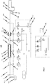
- FIGS. 4 and 5 schematically powder spray coating apparatuses 100 are shown in which embodiments of the powder sealant pump 1 according to the invention for conveying coating powder from a first powder reservoir 101 to a downstream of the powder sealant pump 1 arranged powder spray coating gun 102 are used.
- the powder spray coating gun 102 instead of the powder spray coating gun 102, another device for spraying coating powder onto an object to be coated or a second powder reservoir can also be used.
- the exemplary embodiment of powder sealant pump 1 according to the invention used therein has a powder inlet 2, which is connected or connectable to first powder reservoir 101 by means of a powder line 103, in particular by means of an intake pipe or the like.
- a powder outlet 3 is provided, which is connected or connectable by means of a powder line 104, in particular by means of a powder hose, to a coating powder inlet 105 of the powder spray coating gun 102.
- both the powder inlet 2 and the powder outlet 3 of the powder sealant pump 1 are each formed as a hose connection piece to which the corresponding powder line 103 and 104 attachable and can be fixed with a hose clamp.
- the powder inlet 2 and the powder outlet 3 come into question.
- the powder sealant pump 1 is characterized in that it is designed as a single-chamber powder seal pump, wherein for conveying coating powder from the first powder reservoir 101 to the powder spray coating gun 102 or to another device for spray coating of objects or to another powder reservoir only a single powder conveying chamber 4 is provided.
- the (only) powder delivery chamber 4 has at a first end region a powder inlet 5 which points in the direction of the powder inlet 2 of the powder sealant flow pump 1. Furthermore, the powder delivery chamber 4 has a powder outlet 6 pointing in the direction of the powder outlet 3 of the powder sealant flow pump 1.
- a powder inlet valve 7 is disposed immediately adjacent the powder inlet 5 of the powder delivery chamber 4, in such a way that this powder inlet valve 7 lies between the powder inlet 5 of the powder delivery chamber 4 and the powder inlet 2 of the powder sealant pump 1.
- a powder outlet valve 8 is arranged immediately adjacent to the powder outlet 6 of the powder conveying chamber 4.
- the powder outlet valve 8 is not disposed directly between the powder outlet 6 of the powder delivery chamber and the powder outlet 3 of the powder sealant flow pump 1; Rather, between the powder outlet 8 and the powder outlet 3 of the powder seal current pump 1, an additional compressed air inlet device 9 is arranged. As will be described in more detail below, this additional compressed air inlet device 9 is used for supplying additional transport compressed air as needed into the powder path between the powder outlet valve 8 and the powder outlet 3 of the powder sealant pump 1.
- auxiliary compressed air inlet device 9 between the powder outlet valve 8 and the powder outlet 3 of the powder seal current pump 1.
- the effects achievable with the additional compressed air inlet device 9, which are described in more detail below, can also be realized when the additional compressed air inlet device 9 is arranged behind the powder outlet 3 of the powder seal current pump 1.
- the powder inlet 2 of the powder sealant pump 1, the powder inlet valve 7, the powder inlet 5 of the powder delivery chamber 4, the powder delivery chamber 4, the powder outlet 6 of the powder delivery chamber 4, the auxiliary compressed air inlet device 9 and the powder outlet 3 of the powder seal flow pump 1 lie along a common longitudinal axis
- the powder inlet 2 of the powder sealant flow pump 1 is provided at the opposite end of the powder outlet 3 of the powder sealant flow pump 1.
- the powder feed chamber 4 is formed between its powder inlet 5 and its powder outlet 6 through the cylindrical wall of a tubular filter 10, which is permeable to air, but not for coating powder and may for example consist of sintered material.
- the filter 10 designed as a filter tube is surrounded by an intermediate chamber 11, which is bounded on its outer side by a housing 12 of the powder delivery chamber 4.
- the powder feed chamber 4 is alternately supplied with transport compressed air from a compressed air supply line 50 or with vacuum or vacuum of a vacuum source 52 acted upon.
- the vacuum source 52 an injector 55, which injector compressed air from a compressed air supply line 54 and a compressed air source 58, for example via a pressure regulator 53 and another control valve V2, are supplied.
- the powder outlet valve 8 arranged at the powder outlet 6 of the powder feed chamber 4 is closed and that between the powder inlet 2 of the powder seal flow pump 1 and the powder inlet 5 of the powder conveying chamber 4 arranged powder inlet valve 7 is opened. Simultaneously with the actuation of the powder outlet valve 8 and the powder inlet valve 7 or immediately thereafter, the powder feed chamber 4 is connected to the vacuum source 52 via the control valve V1 and the associated air exchange opening 13 so that a vacuum is applied in the powder feed chamber 4 and coating powder from the first powder reservoir 101 can be sucked.
- the powder inlet valve 7 is closed and the powder outlet valve 8 is opened, while the control valve V1 a fluid connection of the air exchange opening 13 with the compressed air supply line 50, so that the coating powder portion previously sucked into the powder feed chamber 4 during the suction phase is discharged through the open powder discharge valve 8 by means of the conveying compressed air supplied through the air exchange port 13.
- pump cycle is understood to mean a cycle consisting of a suction phase and an ejection phase.
- valves are preferably designed in each case as a pinch valve, although other valve types come into question in principle.
- the powder inlet and powder outlet valves 7, 8 designed as pinch valve in the exemplary embodiment shown in the drawings each have a flexible elastic hose 14.1, 14.2, which serves as a valve channel.
- the flexible elastic hose 14.1, 14.2 can be crimped together to close the corresponding valve (powder inlet valve 7, powder outlet valve 8) by means of actuating compressed air in a pressure chamber 15.1, 15.2 surrounding the flexible elastic tube 14.1, 14.2.
- an air exchange opening 16 is provided in each pressure chamber 15.1, 15.2 in each case, which is connected to a corresponding control valve V3, V4.
- the control valves V3, V4 serve, alternately, the pressure chambers 15.1, 15.2 of the two powder inlet valves, each designed as a pinch valve. or powder outlet valves 7, 8 to pressurize with pressure from a compressed air supply line 56.
- the compressed air supply line 56 is connected to a pressure accumulator 57, wherein the accumulator 57 in turn is connected to a compressed air source 58.
- the compressed air supply line 56 is connected directly to the compressed air source 58 (i.e., without the interposition of a pressure accumulator 57).
- the flexible elastic hose 14.1, 14.2 of the powder inlet valve 7 or powder outlet valve 8 designed as a pinch valve preferably has such an elasticity or internal stress that it automatically stretches again after the pressure of the actuating compressed air in the pressure chamber 15.1, 15.2 disappears, thereby opening the corresponding valve channel.
- a negative pressure is applied via the corresponding air exchange openings 16.
- the powder sealant pump 1 is structurally constructed and constructed so that the pumping frequency achievable with the powder sealant pump 1 can be increased as compared with the pumping frequency achievable with conventional multi-chamber powder sealant pumps.
- a material block 60 is used, in which in advantageous realizations of the powder sealant pump 1 according to the invention the powder inlet valve 7 required for conveying coating powder and also the powder outlet valve 8 required for conveying coating powder, including those for actuating these valves 7, 8 required control valves V3, V4 may be attached (not explicitly shown in the drawings).
- Both the powder inlet valve 7 and the powder outlet valve 8 and the control valves V3, V4 required for the actuation thereof are preferably connected to channels formed in the material block 60 (not shown in the figures).
- the corresponding control valves V1, V3 and V4 and the powder inlet and powder outlet valves 7, 8 are arranged as close as possible to the components of the powder sealant pump 1 to be switched, it is avoided that in the corresponding pressure lines are pneumatically actuated valves 7, 8 or in the corresponding pressure line to the air exchange opening 13 of the powder delivery chamber 4 large volumes present, which must be selectively evacuated during alternate operation of the powder seal pump 1 or filled with compressed air. This can prevent that excessive reaction delay times occur, which would ultimately limit the frequency with which the powder sealant pump 1 can promote coating powder.
- the Pulverdichtstromstromstrompumpe 1 advantageously has a modular structure in which the components "powder inlet 2 of the powder sealant pump 1", “powder inlet valve 7", “powder delivery chamber 4", “Pulverauslassventil 8" and “additional compressed air inlet device 9" are each formed as a modular component together with "powder outlet 3 of the powder sealant pump 1".
- the module constituting the powder inlet 2 of the powder sealant flow pump 1 is indicated by the reference numeral "61" in the drawings, while the module 62 disposed downstream thereof constitutes the powder inlet valve 7.
- the modules 63 and 64 form the powder feed chamber 4 and the powder outlet valve 8, while the module 65 forms the combination of the auxiliary compressed air inlet device 9 and the powder outlet 3 of the powder seal current pump 1.
- the individual modules 61, 62, 63, 64 and 65 are aligned axially with respect to the common longitudinal axis L and mounted one behind the other on the block of material 60.
- the modular design of the powder sealant pump 1 simplifies the maintenance of the pump considerably, since if necessary, for example in the case of a defect or for the purpose of maintenance and / or cleaning, the individual modules 61, 62, 63, 64 and 65 of the pump with the corresponding components can be easily and especially quickly replaced.
- the susceptibility of the pump to failure is greater than that of conventional multi-chamber powder seal pumps in which at least four powder valves and one correspondingly Higher number of control valves for control of the powder valves must be used, significantly reduced.
- the number of wear parts in the powder seal current pump 1 according to the invention is reduced to a minimum, so that a correction of the settings of the powder seal current pump 1 due to wear parts much rarer to perform and a high reproducibility of the settings of the pump is guaranteed.
- the single chamber design used in the powder seal current pump 1 according to the invention allows a particularly compact design of the pump.
- powder delivery of up to 400 g of coating powder per minute can be achieved (width of the pump: 40 mm).
- a filter tube 17 which has a circumference of at least 180 ° (in the illustrated embodiments, a circumference of 360 °) and at least a partial length of the corresponding powder path, a channel wall inner surface to at least 180 ° (in the embodiments shown in the drawings, a channel wall inner surface to 360 °) forms the Pulverwegiscuses.
- the auxiliary compressed air inlet device 9 has a filter tube 17 which surrounds the corresponding powder path for at least a partial length of 360 ° so that the powder ejected from the powder feed chamber 4 of the powder seal current pump 1 during a powder ejection phase Powder portion through the filter tube 17 formed by the filter tube 17 can flow homogeneously.
- compressed air chamber 19 surrounds the filter tube 17 on its outer circumference.
- the compressed air chamber 19 designed here as a compressed air ring chamber is surrounded at its radially inner periphery by the filter tube 17 and at a distance from the filter tube 17 at its radially outer periphery by a housing 20.
- an air exchange opening 21 is introduced, via which, if necessary, compressed air can flow from a compressed air line 59 via a control valve V5 in the compressed air chamber 19 and from there through the filter tube 17 into the filter tube channel 18.
- the compressed air chamber 19 and the filter tube channel 18 formed by the filter tube 17 must be designed to be correspondingly larger in volume.
- the filter tube 17 of the additional compressed air inlet device 9 of microporous material is such that it is permeable to air, but not for coating powder.
- the filter tube 17 is preferably made of a sintered body, for example of metal or plastic, or of a metal or plastic-containing material mixture. Furthermore, it may consist of a different material and / or be formed by a filter membrane.
- the filter pores of the filter tube 17 are preferably designed such that compressed air is passed into the powder path via a powder path region which is large in the circumferential direction as well as in the longitudinal direction of the powder path.
- These micropores of the powder tube 17 may be inclined radially or in the axial direction to the powder path and / or open tangentially to Pulverweghold from the filter tube 17 into the filter tube channel 18 and direct the compressed air accordingly. Due to the large surface of the filter tube 17 on its inner circumference can be homogenized with a small amount of compressed air, the axial powder distribution in the filter tube channel 18 and thus also in the powder path downstream of the powder outlet 3 of the powder seal 1. As a result, pulsations of the powder flow in the powder path can be avoided or at least reduced. Furthermore, a homogenization of the powder density in the longitudinal direction and over the cross section of the powder path can be achieved.
- the transport compressed air quantity per unit time fed into the powder path can be kept so small that it has no or only a small influence on the flow velocity of the coating powder in the flow path.
- the compressed air additionally fed with the additional compressed air inlet device 9 into the powder path of the powder sealant pump 1 can flow in the form of jets or in the form of small air bubbles from the filter tube 17 into the filter tube channel 18, depending on the type of filter pores and the air pressure.
- the filter tube 17 of the auxiliary compressed air inlet device 9 should extend around the powder path for at least 180 ° of the powder path circumference, preferably over the full 360 ° of the powder path circumference.
- the filter tube 17 of the auxiliary compressed air inlet device 9 is preferably a rigid body. But it could also be a flexible body.
- the additional compressed air of the additional compressed air inlet device 9 is pulsed at a pulse frequency which is equal to or preferably greater than the frequency of the powder delivery chamber 4, with which the powder delivery chamber 4 delivers powder portions.
- a pulsating compressed air source or a compressed air pulse generator for the additional compressed air inlet device 9 can be provided.
- a control device 90 is provided, which is designed such that the pulse frequency the additional compressed air inlet device 9 supplied additional compressed air is adjustable in dependence on the powder delivery frequency of the powder delivery chamber 4 in at least one of the following ways: for example, manually adjustable and / or is preferably automatically controlled or preferably controlled.
- the additional compressed air pulse frequency can be increased with increasing Pulverabgabefrequenz and reduced with decreasing Pulverabgabefrequenz.
- control device 90 may advantageously be designed such that the additional compressed air quantity flowing through the additional compressed air inlet device 9 per unit time can be set in at least one of the following ways depending on the delivered powder quantity: for example manually adjustable is and / or preferably automatically controllable or preferably controllable.
- the control device 90 of the powder spray coating device 100 can be designed for the mentioned setting of the additional compressed air pulse frequency or for the said setting of the additional compressed air quantity, or for both settings.
- the controller 90 may include all controls, or two or more controllers may be provided. If it is desired to set the additional compressed air pulse frequency or the additional compressed air flow rate manually, a manual adjusting element can be provided for each of these.
- the powder inlet valve 7 and the powder outlet valve 8 of the powder seal current pump 1 according to the invention are each preferably designed as pinch valves, since less coating powder can be deposited in pinch valves than in other valve types, and because powder deposits due to the air flow in let them clean easily.
- Pinch valves are controllable by means of compressed air or by means of negative pressure valves. In principle, however, other controllable valves are used.
- automatic valves such as ball valves or flap valves, which are controlled by the differential pressure between the valve inlet side and the Ventilauslassseite and thus automatically by the pressure and negative pressure, which prevails in the powder feed chamber 4.
- control device 90 To control the operation of the powder seal current pump 1, the already mentioned control device 90 is used, which in Fig. 3 is indicated schematically.
- the control device 90 is designed to suitably control the individual controllable components of the powder seal current pump 1, in particular the control valves V1, V2, V3, V4 and V5, and to coordinate their actuation.
- FIGS. 4 and 5 schematically illustrated embodiments of the powder spray coating device 100 according to the invention is still another control valve V6 provided, via which in a cleaning cycle of the powder sealant pump 1, the powder feed chamber 4 can be acted upon by high pressure.
- the control device 90 is preferably designed such that it opens the control valve V4 in preparation for the suction phase of the powder delivery chamber 4, so that the compressed air provided in the pressure accumulator 57 or by the compressed air source 58 via the compressed air supply line 56 and the air exchange opening 16 in the pressure chamber 15.2 of as a pinch valve formed powder outlet valve 8 is passed.
- the flexible elastic tube 14.2 of the powder discharge valve 8 formed as the pinch valve is squeezed, as a result of which the powder path provided by the flexible elastic tube 14.2 is closed by the powder discharge valve 8.
- the air exchange opening 13 provided in the housing 12 of the powder delivery chamber 4 is fluidly connected to the vacuum source 52 by means of the control means 90 to generate a negative pressure inside the powder delivery chamber 4, so that coating powder through the powder inlet 2 of the powder seal 1 and the (opened) powder inlet valve 7 and the powder inlet 5 of the powder feed chamber 4 can be sucked into the powder feed chamber 4.
- the predetermined delay time is preferably in the range between 0 ms and 50 ms for a delivery cycle of the powder delivery chamber 4 of approximately 200 ms.
- control valve V3 is fluidly connected to the compressed air supply line 56, as a result of which an overpressure is applied in the pressure chamber 15.1 of the pinch valve formed powder inlet valve 7, which causes a squeezing of the flexible elastic tube 14.1 designed as a pinch valve Pulereinlassventils 7.
- the powder intake valve 7 is closed.
- the control valve V4 switches the air exchange opening 17 of the pressure chamber 15.2 of the powder outlet valve 8 designed as a pinch valve depressurized or vents the pressure chamber 15.2. Due to the elasticity of the hose 14.2 of the powder outlet valve 8 designed as a pinch valve, this then passes directly into its open state.
- control valve V1 is switched such that the air exchange opening 13 formed in the housing 12 of the powder delivery chamber 4 is fluidly connected to the compressed air source 58.
- the compressed air then flows via the compressed air supply line 50, the control valve V1, the intermediate chamber 11 and the filter element 10 into the powder feed chamber 4 and drives the previously sucked powder portion from the powder outlet 6 of the powder feed chamber 4.
- the powder portion is transported further through the opened powder outlet valve 8, the filter tube channel 18 of the auxiliary compressed air inlet device 9 and the powder outlet 3 of the powder seal current pump 1.
- the control device 90 is designed, in particular, to feed pulse-type additional transport compressed air into the powder path between the powder outlet valve 8 and the powder outlet 3 of the powder seal current pump 1 via the additional compressed air inlet device 9.
- additional transport compressed air is always fed during the entire or during a predetermined or predeterminable period of the suction phase of the powder feed chamber 4, in order to effectively pulsations in to avoid or minimize the powder flow discharged from the powder seal current pump 1.
- the controller 90 is configured to always communicate the air exchange port 21 of the compressed air chamber 19 of the auxiliary compressed air intake device 9 with the compressed air source 58 whenever the powder discharge valve 8 is closed.
- the individual compressed air supply lines 50, 54, 56 and 59 run into a control unit 91 in which the compressed air supply of the individual components of the powder spray coating device 100 is coordinated and controlled.
- the per unit time of the powder spray coating gun 102 via the compressed air input 106 of the powder spray coating gun 102 amount of additional compressed air, which serves to atomize, for shaping and / or otherwise influencing the spray powder to be sprayed by the powder spray coating gun 102, and / or the amount of electrode scavenging air supplied per unit time of the powder spray coating gun 102 via the compressed air inlet 107 of the powder spray coating gun 102.
- auxiliary compressed air inlet device 9 used filter tube 17 and the filter 10 used in the powder conveying chamber 4 to understand. In this way, it is ensured that the transport compressed air introduced into the powder feed chamber 4 during the discharge phase experiences the same pneumatic resistance as the additional compressed air which is fed into the powder path downstream of the powder outlet valve 8 via the auxiliary compressed air inlet device 9 during the powder suction phase.
- the solution according to the invention is not limited to a powder sealant pump 1, which has a powder inlet 2 at a first end region and a powder outlet 3 at an opposite second end region, which in the illustrations according to FIGS FIGS. 1 to 5 is shown. Rather, the solution according to the invention is also suitable for embodiments in which - as in the FIGS. 6 and 7 schematically illustrated - the only powder conveying chamber 4 of the powder sealant pump 1 at one end region has a powder passage 30 which serves both as a powder inlet and as a powder outlet for the powder feed chamber 4. In the in the FIGS.
- the powder inlet 2 of the powder seal stream pump 1 is fluidly connected to the powder passage 30 of the powder conveying chamber 4 via the powder inlet valve 7 and the powder outlet 3 of the powder seal stream pump 1 via the powder outlet valve 8.
- a distributor 31 is used, in the in the FIGS. 6 and 7 illustrated embodiments is designed as a Y-piece.
- this manifold 31 of the powder passage 30 of the powder feed chamber 4 with the powder inlet valve 7 on the one hand and the powder outlet valve 8 on the other hand fluidly connected.
- Fig. 7 schematically illustrated embodiment of the powder sealant pump 1 differs from the in Fig. 6 shown embodiment in that the auxiliary compressed air inlet device 9 is identical to the transport compressed-air inlet device of the powder feed chamber 4 designed to equate the occurring during the introduction of the transporting compressed air and the introduction of the additional compressed air pneumatic resistors.
- FIGS. 7 and 8 illustrated embodiments correspond to the components of the embodiments according to FIGS FIGS. 1 to 5 , in which connection reference is made to the previous statements.
- the invention is not limited to the embodiments of the powder sealant pump according to the invention shown in the drawings, but results from a synopsis of all features disclosed herein.
Description
Die vorliegende Erfindung betrifft eine Pulverdichtstrompumpe zum Fördern von Beschichtungspulver nach dem Oberbegriff des unabhängigen Patentanspruches 1.The present invention relates to a powder sealant pump for conveying coating powder according to the preamble of
Demgemäß betrifft die Erfindung insbesondere eine Pulverdichtstrompumpe zum Fördern von Beschichtungspulver von einem ersten Pulverreservoir zu einem stromabwärts der Pulverdichtstrompumpe angeordneten zweiten Pulverreservoir oder einer stromabwärts der Pulverdichtstrompumpe angeordneten Pulversprühbeschichtungspistole oder dergleichen Einrichtung zum Versprühen von Beschichtungspulver.Accordingly, the invention particularly relates to a powder sealant pump for conveying coating powder from a first powder reservoir to a second powder reservoir located downstream of the powder seal pump or a powder spray coating gun or powder coating jet powder downstream of the powder seal pump or the like powder coating powder.
Die Druckschrift
Die Erfindung betrifft ferner ein Verfahren zum Fördern von Beschichtungspulver von einem ersten Pulverreservoir zu einem stromabwärts von dem ersten Pulverreservoir angeordneten zweiten Pulverreservoir oder einer stromabwärts von dem ersten Pulverreservoir angeordneten Pulversprühbeschichtungspistole oder dergleichen Einrichtung zum Versprühen von Beschichtungspulver. Pulverdichtstrompumpen (engl.: dense phase powder pumps) der eingangs genannten Art sind dem Prinzip nach aus dem Stand der Technik bekannt.The invention further relates to a method for conveying coating powder from a first powder reservoir to a second powder reservoir arranged downstream of the first powder reservoir or to a powder spray coating gun or the like for spraying coating powder arranged downstream of the first powder reservoir. Dense phase powder pumps (dense phase powder pumps) of the type mentioned are known in principle from the prior art.
Beispielsweise betrifft die Druckschrift
Im Einzelnen ist dabei vorgesehen, dass im ansaugseitigen bzw. förderseitigen Bereich der Pulverdichtstrompumpe die mit den jeweiligen Pulverförderkammern der Pulverdichtstrompumpe verbundenen Pulverschläuche mit einem mechanisch betätigten Stempel deformierbar sind, um den Schlauchabschnitt bei Bedarf abzuquetschen bzw. zu öffnen. Jeder Pulverförderkammer der aus diesem Stand der Technik bekannten Pulverdichtstrompumpe ist ein Filterrohr zugeordnet, welches den Umfang der entsprechenden Pulverförderkammer begrenzt. Das Filterrohr ist für Luft, jedoch nicht für Beschichtungspulver durchlässig und von einer Ringkammer umgeben, an die wechselweise Unterdruck oder Druckluft anschließbar ist. Dadurch kann in jede Pulverförderkammer wechselweise Beschichtungspulver eingesaugt oder mittels Druckluft aus der entsprechenden Pulverförderkammer ausgestoßen werden. Die beiden zueinander parallel angeordneten Pulverförderkammern werden wechselphasig betrieben, was bedeutet, dass eine der beiden Pulverförderkammern Beschichtungspulver durch den Pulvereinlass der Pulverdichtstrompumpe ansaugt, während die andere der beiden Pulverförderkammern eine zuvor in die Pulverförderkammer angesaugte Beschichtungspulverportion über den Pulverauslass der Pulverdichtstrompumpe abgibt.In detail, it is provided that in the suction-side or delivery-side region of the powder seal pump, the powder hoses connected to the respective powder delivery chambers of the powder seal pump are deformable with a mechanically actuated plunger to squeeze or open the hose section as needed. Each powder feed chamber of the known from this prior art powder seal pump is associated with a filter tube which limits the circumference of the corresponding powder feed chamber. The filter tube is permeable to air but not to coating powder and surrounded by an annular chamber to which alternate negative pressure or compressed air can be connected. As a result, coating powder can be alternately sucked into each powder feed chamber or ejected by means of compressed air from the corresponding powder feed chamber. The two powder feed chambers arranged parallel to one another are operated in an alternating phase, which means that one of the two powder feed chambers sucks coating powder through the powder inlet of the powder seal pump while the other of the two powder feed chambers releases a coating powder portion previously sucked into the powder feed chamber via the powder outlet of the powder seal pump.
Pulverdichtstrompumpen mit mehren, insbesondere zwei parallel zueinander geschalteten Pulverförderkammern sind auch aus der Druckschrift
Die Verwendung von Pulverdichtstrompumpen zur Förderung von Beschichtungspulver zu entsprechenden Einrichtungen zum Versprühen von Beschichtungspulver, wie insbesondere Pulversprühbeschichtungspistolen, ist aus der Druckschrift
Bevor die Verwendung von Pulverdichtstrompumpen der eingangs genannten Art zur Förderung von Beschichtungspulver bekannt wurde, wurden als Injektoren ausgebildete Pulverpumpen verwendet, welche auch heute noch zur Förderung von Beschichtungspulver eingesetzt werden. Im Unterschied zu Pulverdichtstrompumpen der eingangs genannten Art weisen als Injektoren ausgebildete Pulverpumpen jedoch den Nachteil auf, dass die mit als Injektoren ausgebildete Pulverpumpen üblicherweise nur eine geringere Menge an Beschichtungspulver pro Zeiteinheit fördern können.Before the use of powder sealant pumps of the aforementioned type for the promotion of coating powder became known, trained as injectors powder pumps were used, which are still used today for the promotion of coating powder. In contrast to powder seal pumps of the type mentioned have trained as injectors powder pumps however, has the disadvantage that the powder pumps designed as injectors usually can only convey a smaller amount of coating powder per unit of time.
Insofern haben sich Pulverdichtstrompumpen der eingangs genannten Art in der Praxis insbesondere für solche Anwendungen durchgesetzt, bei denen eine relativ große Menge an Beschichtungspulver pro Zeiteinheit zu fördern ist.In this respect, powder seal pumps of the type mentioned in practice have prevailed in particular for those applications in which a relatively large amount of coating powder per unit time is to promote.
Im praktischen Gebrauch hat sich jedoch gezeigt, dass eine Pulverdichtstrompumpe, wie sie beispielsweise aus der Druckschrift
Dadurch, dass bei den herkömmlichen Pulverdichtstrompumpen eingangsseitig mindestens zwei Pulvereinlassventile und ausgangsseitig mindestens zwei Pulverauslassventile Verwendung finden, ist zwangsläufig eine wartungsfreie Laufzeit der Pulverdichtstrompumpe entsprechend reduziert.Due to the fact that at least two powder inlet valves and at least two powder outlet valves are used on the input side in the conventional powder seal pumps, a maintenance-free running time of the powder seal pump is inevitably reduced accordingly.
Darüber hinaus verlangen herkömmliche Pulverdichtstrompumpen ein relativ aufwendiges Schaltdiagramm, um die einzelnen wechselweise anzusteuernden Komponenten der Pumpe koordiniert ansteuern zu können.In addition, conventional powder seal pumps require a relatively complicated circuit diagram in order to be able to coordinately control the individual components of the pump which are to be actuated alternately.
Auf Grundlage dieser Problemstellung liegt der vorliegenden Erfindung die Aufgabe zugrunde, eine Pulverdichtstrompumpe der eingangs genannten Art dahingehend weiterzubilden, dass diese mit weniger wartungsanfälligen Komponenten auskommt, wobei gleichzeitig die Pulverförderleistung der Pumpe möglichst unverändert bleibt.Based on this problem, the present invention has the object, a powder sealant pump of the type mentioned in such a way that it manages with less maintenance-prone components, while the powder delivery rate of the pump remains unchanged as possible.
Darüber hinaus ist es eine Aufgabe der Erfindung, eine Pulverdichtstrompumpe der eingangs genannten Art strukturell einfacher aufzubauen und insbesondere zu vereinfachen bzw. zu verkleinern.Moreover, it is an object of the invention to structurally simpler to build a powder seal pump of the type mentioned and in particular to simplify or reduce.
Des Weiteren soll ein entsprechend vereinfachtes Verfahren zum Fördern von Beschichtungspulver angegeben werden.Furthermore, a correspondingly simplified method for conveying coating powder should be specified.
Im Hinblick auf die Vorrichtung wird die der Erfindung zugrunde liegenden Aufgabe erfindungsgemäß durch den Gegenstand des unabhängigen Patentanspruches 1 gelöst.With regard to the device, the object underlying the invention is achieved by the subject matter of
Im Hinblick auf das Verfahren wird die der Erfindung zugrunde liegende Aufgabe durch den Gegenstand des nebengeordneten Patentanspruches 14 gelöst.With regard to the method, the object underlying the invention is achieved by the subject matter of the independent claim 14.
Vorteilhafte Weiterbildungen der erfindungsgemäßen Pulverdichtstrompumpe sind in den abhängigen Patentansprüchen 2 bis 12 angegeben.Advantageous developments of the powder seal current pump according to the invention are specified in the
Demnach wird erfindungsgemäß insbesondere eine Pulverdichtstrompumpe zum Fördern von Beschichtungspulver von einem ersten Pulverreservoir zu einem zweiten (im Hinblick auf das erste Pulverreservoir) stromabwärts angeordneten Pulverreservoir oder einer stromabwärts angeordneten Pulversprühbeschichtungspistole oder dergleichen Einrichtung zum Versprühen von Beschichtungspulver angegeben, wobei die Pulverdichtstrompumpe als Ein-Kammer-Pulverdichtstrompumpe ausgebildet ist und zur Förderung des Beschichtungspulvers insbesondere nur eine einzige Pulverförderkammer aufweist.Accordingly, according to the invention, in particular a powder sealant pump for conveying coating powder from a first powder reservoir to a second (with regard to the first powder reservoir) downstream powder reservoir or a downstream powder spray coating gun or the like device for spraying coating powder is specified, the powder sealant pump as a single-chamber Powder sealant pump is formed and in particular has only a single powder conveying chamber for conveying the coating powder.
Der erfindungsgemäßen Lösung liegt die überraschende Erkenntnis zugrunde, dass auch mit einer Ein-Kammer-Pulverdichtstrompumpe, d.h. einer Pulverdichtstrompumpe, die zur Förderung des Beschichtungspulvers nur eine einzige Pulverförderkammer aufweist, eine für den praktischen Gebrauch hinreichende kontinuierliche Förderung von Beschichtungspulver möglich wird.The solution according to the invention is based on the surprising finding that even with a single-chamber powder sealant pump, i. a powder sealant pump, which has only a single powder delivery chamber for conveying the coating powder, a sufficient continuous promotion of coating powder is possible for practical use.
Das bislang existierende Vorurteil der Fachwelt, nämlich dass zur kontinuierlichen Förderung von Beschichtungspulver mindestens zwei parallel angeordnete und wechselweise betriebene Pulverförderkammern zum Einsatz kommen müssen, wurde mit der vorliegenden Erfindung dadurch überwunden, dass eine als Ein-Kammer-Pulverdichtstrompumpe ausgebildete Pulverdichtstrompumpe durchaus eine kontinuierliche Förderung von Beschichtungspulver gewährleisten kann, insbesondere dann, wenn bei der als Ein-Kammer-Pulverdichtstrompumpe ausgebildeten Pulverdichtstrompumpe die Pump-Frequenz, d.h. die Frequenz, mit welcher Beschichtungspulver von der einzigen Pulverförderkammer eingesaugt und dann wieder abgegeben wird, entsprechend erhöht wird, und/oder wenn am Pulverauslass der einzigen Pulverförderkammer strömungsmäßig vor oder nach dem Pulverauslass der Pulverdichtstrompumpe zu geeigneten Zeiten Zusatzdruckluft als zusätzliche Transportdruckluft in den Pulverweg eingeleitet wird.The previously existing prejudice of the art, namely that for the continuous promotion of coating powder at least two parallel arranged and alternately operated powder feed chambers must be used, was overcome with the present invention in that a designed as a single-chamber powder seal pump Pulverdichtstrumpumpe thoroughly can ensure a continuous delivery of coating powder, especially when the pump frequency, ie the frequency at which coating powder is sucked in from the single powder conveying chamber and then discharged again, is increased correspondingly in the powder sealant pump designed as a single-chamber powder sealant pump, and / or if additional compressed air is introduced into the powder path as additional transport compressed air at appropriate times at the powder outlet of the single powder feed chamber before or after the powder outlet of the powder seal current pump.
Durch Einleitung von Zusatzdruckluft in den Pulverweg kann die Pulverkonzentration in dem Pulverweg homogenisiert werden.By introducing additional compressed air into the powder path, the powder concentration in the powder path can be homogenized.
Durch das gezielte Einleiten von Zusatzdruckluft in den Pulverweg am Pulverauslass der Pulverförderkammer kann insbesondere erreicht werden, dass in der Pulverleitung stromabwärts des Pulverauslasses der Pulverdichtstrompumpe die Strömungsgeschwindigkeit des geförderten Pulvers einen konstanten Wert annimmt und das Pulver durch die Pulverleitung homogen hindurch strömen kann. Hierbei ist es insbesondere von Vorteil, wenn die je Pumpenzyklus im Pulverweg zugeführte Menge an Zusatzdruckluft gleich oder zumindest im Wesentlichen gleich ist wie die je Pumpenzyklus in die Pulverförderkammer eingespeiste Menge an Transportdruckluft, die zum pneumatischen Ausstoßen von Pulverportionen aus der Pulverförderkammer dient.By selectively introducing additional compressed air into the powder path at the powder outlet of the powder delivery chamber, it can be achieved in particular that the flow rate of the conveyed powder assumes a constant value in the powder line downstream of the powder outlet of the powder sealant pump and the powder can flow homogeneously through the powder line. It is particularly advantageous if the per pump cycle in the powder path supplied amount of additional compressed air is equal to or at least substantially equal to the per pump cycle fed into the powder feed chamber amount of transport compressed air, which is used for pneumatic ejection of powder portions from the powder feed chamber.
Indem die Pump-Frequenz der als Ein-Kammer-Pulverdichtstrompumpe ausgebildeten Pulverdichtstrompumpe, also die Frequenz, mit welcher Beschichtungspulver in die einzige Pulverförderkammer der als Ein-Kammer-Pulverdichtstrompumpe ausgebildeten Pulverdichtstrompumpe eingesaugt und dann wieder abgegeben wird, entsprechend erhöht wird, und/oder indem insbesondere pulsweise und mit der Pump-Frequenz der als Ein-Kammer-Pulverdichtstrompumpe ausgebildeten Pulverdichtstrompumpe koordiniert Zusatzdruckluft in den Pulverweg stromabwärts des Pulverauslasses der Pulverförderkammer eingeleitet wird, kann die Fließfähigkeit des von der Pulverdichtstrompumpe geförderten Beschichtungspulvers stromabwärts der Pulverdichtstrompumpe verbessert werden. Insbesondere ist durch mindestens einer dieser Maßnahmen eine gleichmäßige Pulverförderung von der Pulverdichtstrompumpe zu einem von der Pulverdichtstrompumpe stromabwärts liegenden Pulverreservoir oder einer von der Pulverdichtstrompumpe stromabwärts liegenden Pulversprühbeschichtungspistole oder dergleichen Einrichtung zum Versprühen von Beschichtungspulver möglich.By correspondingly increasing the pumping frequency of the powder sealant pump designed as a single-chamber powder sealant pump, ie the frequency with which coating powder is sucked into the single powder delivery chamber of the powder sealant pump designed as a one-chamber powder sealant pump and then released again, and / or by In particular, pulsed and coordinated with the pumping frequency of the powder sealant pump constructed as a single-chamber powder sealant pump, additional pressurized air is introduced into the powder path downstream of the powder outlet of the powder feed chamber, the flowability of the coating powder conveyed by the powder sealant pump can be improved downstream of the powder sealant pump. In particular, by at least one of these measures a uniform powder delivery from the powder seal pump to one of the powder seal downstream pump reservoir or one of the powder seal pump downstream powder spray coating gun or the like means for spraying coating powder possible.
Im Vergleich zu herkömmlichen Pulverdichtstrompumpen, die als Mehr-Kammer-Pulverdichtstrompumpen ausgebildet sind und mehrere, insbesondere mindestens zwei parallel zueinander angeordnete und gegenphasig zueinander betriebene Pulverförderkammern aufweisen, kann mit der Pulverdichtstrompumpe gemäß der vorliegenden Erfindung eine Pulverförderung mit einer vergleichbaren Gleichmäßigkeit ohne Strömungspulsationen im Pulverweg stromabwärts des Pulverauslasses der Pulverdichtstrompumpe erzielt werden, wobei andererseits jedoch die Anzahl der im Betrieb der Pulverdichtstrompumpe zu betätigenden Komponenten deutlich reduziert und der strukturelle Aufbau der Pulverdichtstrompumpe deutlich vereinfacht ist.Compared to conventional powder seal pumps, which are designed as multi-chamber Pulverdichtstrumpumpumpen and more, in particular at least two mutually parallel and in opposite phase operated Pulverförderkammern, with the powder sealant pump according to the present invention, a powder delivery with a comparable uniformity without flow pulsations downstream in the powder path On the other hand, however, the number of operating in the powder seal pump to be actuated components significantly reduced and the structural design of the powder seal pump is significantly simplified.
Die vorliegende Erfindung liefert somit bei gleichzeitiger Reduzierung der strukturellen Komponenten und bei gleichzeitiger Vereinfachung des zum Betrieb der Pulverdichtstrompumpe erforderlichen Schaltdiagramm eine besonders leicht zu realisierende aber dennoch effektive Alternative zu herkömmlichen als Mehr-Kammer-Pulverdichtstrompumpen ausgeführten Pulverdichtstrompumpen.Thus, while reducing the structural components and simultaneously simplifying the circuitry required to operate the powder sealant pump, the present invention provides a particularly easy-to-implement yet effective alternative to conventional powder sealant pumps constructed as multi-chamber powder sealant pumps.
Gemäß einem Aspekt der vorliegenden Erfindung weist die Pulverdichtstrompumpe einen mit dem (stromaufwärts liegenden) ersten Pulverreservoir verbundenen oder verbindbaren Pulvereinlass und einen mit dem (stromabwärts liegenden) zweiten Pulverreservoir bzw. mit der (stromabwärts liegenden) Pulversprühbeschichtungspistole oder dergleichen Einrichtung zum Versprühen von Beschichtungspulver verbundenen oder verbindbaren Pulverauslass auf. Dabei kann der Pulvereinlass der Pulverdichtstrompumpe an einem ersten Endbereich der Pulverdichtstrompumpe und der Pulverauslass der Pulverdichtstrompumpe an einem gegenüberliegenden zweiten Endbereich der Pulverdichtstrompumpe angeordnet sein, wobei die (einzige) Pulverförderkammer der Pulverdichtstrompumpe zwischen dem Pulvereinlass und dem Pulverauslass der Pulverdichtstrompumpe angeordnet ist.According to one aspect of the present invention, the powder sealant pump has a powder inlet connected or connectable to the (upstream) first powder reservoir and a powder powder spraying device or the like powder powder spraying apparatus (downstream) connectable powder outlet on. Here, the powder inlet of the powder sealant pump may be disposed at a first end portion of the powder sealant flow pump and the powder outlet of the powder sealant flow pump at an opposite second end portion of the powder sealant flow pump, the (single) powder delivery chamber of the powder sealant pump being disposed between the powder inlet and the powder outlet of the powder sealant flow pump.
Bei einer vorteilhaften Realisierung der vorliegenden Erfindung, weist die einzige Pulverförderkammer der erfindungsgemäßen Pulverdichtstrompumpe an einem ersten Endbereich einen Pulvereinlass und an einem gegenüberliegenden zweiten Endbereich einen Pulverauslass auf, wobei die erfindungsgemäße Pulverdichtstrompumpe ferner ein Pulvereinlassventil sowie ein Pulverauslassventil aufweist. Über das Pulvereinlassventil ist der Pulvereinlass der (einzigen) Pulverförderkammer mit dem Pulvereinlass der Pulverdichtstrompumpe strömungsmäßig verbunden oder verbindbar. Andererseits ist der Pulverauslass der einzigen Pulverförderkammer der Pulverdichtstrompumpe über das Pulverauslassventil mit dem Pulverauslass der Pulverdichtstrompumpe verbunden oder verbindbar.In an advantageous implementation of the present invention, the single powder feed chamber of the powder seal current pump according to the invention has a powder inlet at a first end region and a powder outlet at an opposite second end region, the powder seal current pump according to the invention further comprising a powder inlet valve and a powder outlet valve. Via the powder inlet valve, the powder inlet of the (single) powder delivery chamber is fluidly connected or connectable to the powder inlet of the powder sealant pump. On the other hand, the powder outlet of the single powder delivery chamber of the powder sealant pump is connected or connectable to the powder outlet of the powder sealant pump via the powder discharge valve.
Gemäß einem anderen Aspekt der vorliegenden Erfindung weist die Pulverdichtstrompumpe einen mit dem ersten Pulverreservoir verbundenen oder verbindbaren Pulvereinlass und einen mit dem zweiten Pulverreservoir bzw. mit der Pulversprühbeschichtungspistole oder dergleichen Einrichtung zum Versprühen von Beschichtungspulver verbundenen oder verbindbaren Pulverauslass auf, wobei die einzige Pulverförderkammer der erfindungsgemäßen Pulverdichtstrompumpe an einem Endbereich einen Pulverdurchgang aufweist, der sowohl als Pulvereinlass als auch als Pulverauslass für die Pulverförderkammer dient. Gemäß diesem Aspekt der vorliegenden Erfindung ist es von Vorteil, wenn die Pulverdichtstrompumpe ferner ein Pulvereinlassventil sowie ein Pulverauslassventil aufweist, wobei über das Pulvereinlassventil der Pulverdurchgang der einzigen Pulverförderkammer mit dem Pulvereinlass der Pulverdichtstrompumpe strömungsmäßig verbunden oder verbindbar ist, und wobei über das Pulverauslassventil der Pulverdurchgang der einzigen Pulverförderkammer mit dem Pulverauslass der Pulverdichtstrompumpe strömungsmäßig verbunden oder verbindbar ist.According to another aspect of the present invention, the powder sealant pump has a powder inlet connected or connectable to the first powder reservoir and a powder outlet connected or connectable to the second powder reservoir or powder spray gun or the like, wherein the single powder feed chamber of the powder seal current pump of the present invention has at one end a powder passage, which serves both as a powder inlet and as a powder outlet for the powder feed chamber. According to this aspect of the present invention, it is advantageous if the powder sealant pump further comprises a powder inlet valve and a powder outlet valve, via the powder inlet valve the powder passage of the single powder feed chamber is fluidly connected or connectable to the powder inlet of the powder sealant pump and via the powder outlet valve the powder passageway single powder delivery chamber is fluidly connected or connectable to the powder outlet of the powder sealant pump.
Gemäß einer bevorzugten Realisierung ist dabei vorgesehen, dass die Pulverdichtstrompumpe ferner einen Verteiler aufweist, um den Pulverdurchgang der Pulverförderkammer mit dem Pulvereinlassventil einerseits und dem Pulverauslassventil andererseits strömungsmäßig zu verbinden. Denkbar hierbei ist es insbesondere, als Verteiler ein Y-Stück zu verwenden. Selbstverständlich kommen aber auch andere Ausführungsformen hierfür in Frage.According to a preferred embodiment, it is provided that the powder sealant pump further comprises a distributor in order to connect the powder passage of the powder feed chamber with the powder inlet valve on the one hand and the powder outlet valve on the other hand in terms of flow. It is conceivable here, in particular, to use a Y-piece as the distributor. Of course, other embodiments come into question for this purpose.
In bevorzugten Ausführungsformen der erfindungsgemäßen Lösung ist ferner eine Steuereinrichtung vorgesehen, welche derart ausgebildet ist, um das Pulvereinlassventil und/oder das Pulverauslassventil der Pulverdichtstrompumpe wechselweise anzusteuern. Die Steuereinrichtung ist vorzugsweise ferner ausgebildet, um abwechselnd einen Überdruck und einen Unterdruck in der (einzigen) Pulverförderkammer der Pulverdichtstrompumpe anzulegen.In preferred embodiments of the solution according to the invention, a control device is furthermore provided, which is designed such that it alternately activates the powder inlet valve and / or the powder outlet valve of the powder sealant pump. The control device is preferably further configured to alternately apply an overpressure and a negative pressure in the (single) powder feed chamber of the powder seal current pump.
Der (einzigen) Pulverförderkammer der Pulverdichtstrompumpe ist vorzugsweise ein Gasweg zugeordnet, durch welchen die Pulverförderkammer wechselweise mit einer Vakuumleitung oder Vakuumquelle zum Einsaugen von Beschichtungspulver in die Pulverförderkammer durch das offene Pulvereinlassventil, während das Pulverauslassventil geschlossen ist, oder mit einer Druckluftleitung oder Druckluftquelle zum pneumatischen Ausstoßen einer in der Pulverförderkammer vorhandenen Pulverportion durch das offene Pulverauslassventil, während das Pulvereinlassventil geschlossen ist, verbindbar ist. Die Steuereinrichtung ist dabei ausgebildet, die einzige Pulverförderkammer wechselweise auf Einsaugen und auf Ausstoßen von Pulver umzuschalten.The (single) powder feed chamber of the powder seal pump is preferably associated with a gas path through which the powder feed chamber alternately with a vacuum line or vacuum source for sucking coating powder into the powder feed chamber through the open powder inlet valve while the powder outlet valve is closed, or with a pneumatic line or compressed air source for pneumatic ejection a powder portion present in the powder feed chamber through the open powder outlet valve, while the powder inlet valve is closed, is connectable. The control device is designed to switch the single powder feed chamber alternately to suction and ejection of powder.
Bei vorteilhaften Realisierungen der erfindungsgemäßen Pulverdichtstrompumpe weist der zuvor genannte Gasweg eine Saugluftöffnung und eine Druckluftöffnung in einer Gehäuseumfangswand der Pulverförderkammer auf, wobei vorzugsweise ferner ein mikroporöses Filterelement, vorzugsweise in Gestalt eines Filterrohres, vorgesehen ist, welches mindestens auf einer Teillänge oder vorzugsweise der gesamten Länge der Pulverförderkammer die Umfangswand der Pulverförderkammer bildet und die Pulverkammer von einer Ringkammer trennt. Die Ringkammer ist zwischen dem Außenumfang des vorzugsweise als Filterrohr ausgebildeten Filterelements und dem Innenumfang der Gehäuseumfangswand gebildet und umgibt das vorzugsweise als Filterrohr ausgebildete Filterelement.In advantageous realizations of the powder sealant pump according to the invention, the aforementioned gas path has a suction air opening and a compressed air opening in a housing peripheral wall of the powder delivery chamber, wherein preferably also a microporous filter element, preferably in the form of a filter tube is provided which at least a partial length or preferably the entire length of the Powder feed chamber forms the peripheral wall of the powder feed chamber and separates the powder chamber of an annular chamber. The annular chamber is formed between the outer periphery of the filter element preferably designed as a filter tube and the inner circumference of the housing peripheral wall and surrounds the filter element preferably designed as a filter tube.
Das vorzugsweise als Filterrohr ausgebildete Filterelement ist für Luft, jedoch nicht für Beschichtungspulver durchlässig aufgrund seiner kleinen Porengröße. Es besteht vorzugsweise aus einem Sintermaterial.The filter element, preferably designed as a filter tube, is permeable to air but not to coating powder because of its small pore size. It is preferably made of a sintered material.
Bei Ausführungsformen, bei denen der Pulvereinlass und Pulverauslass der einzigen Pulverförderkammer an gegenüberliegenden Endbereichen der Pulverförderkammer liegen, ist es von Vorteil, wenn die Saugluftöffnung nahe bei dem Pulverauslass in die Ringkammer mündet, und die Druckluftöffnung nahe bei dem Pulvereinlass in die Ringkammer mündet.In embodiments in which the powder inlet and outlet of the single powder feed chamber are at opposite end portions of the powder feed chamber, it is advantageous if the suction air port opens into the annulus near the powder outlet and the compressed air port opens into the annulus near the powder inlet.
Selbstverständlich ist es aber auch denkbar, sowohl für die Saugluftöffnung als auch für die Druckluftöffnung eine einzige (gemeinsame) Öffnung zu wählen.Of course, it is also conceivable to choose a single (common) opening both for the suction air opening and for the compressed air opening.
Das Pulvereinlassventil und das Pulverauslassventil der bei der erfindungsgemäßen Pulverdichtstrompumpe vorhandenen (einzigen) Pulverförderkammer sind vorzugsweise jeweils als Quetschventil ausgebildet, insbesondere von der Bauweise, welche einen flexiblen elastischen Schlauch als Ventilkanal aufweisen, wobei dieser flexible elastische Schlauch zum Schließen des entsprechenden Ventils mit Hilfe von Betätigungsdruckluft in einer den Schlauch umgebenden Druckkammer zusammenquetschbar ist.The powder inlet valve and the powder outlet valve are the (single) powder delivery chamber present in the powder seal current pump according to the invention preferably each designed as a pinch valve, in particular of the construction, which have a flexible elastic hose as a valve channel, said flexible elastic hose for closing the corresponding valve by means of actuating compressed air in a pressure chamber surrounding the hose is zusammenquetschbar.
Insbesondere ist es in diesem Zusammenhang von Vorteil, wenn das als Quetschventil ausgebildete Pulvereinlassventil und das als Quetschventil ausgebildete Pulverauslassventil jeweils ein Quetschventilgehäuse mit einem Pulvereinlass und einem Pulverauslass sowie mit einem elastisch verformbaren Ventilelement, vorzugsweise in Gestalt eines Schlauchabschnittes, aufweist. Insbesondere sollte dabei das Ventilelement im Inneren des Quetschventilgehäuses derart angeordnet sein, dass der Pulvereinlass des Quetschventils mit dem Pulverauslass des Quetschventils über das als Schlauchabschnitt gebildete Ventilelement in Fluidverbindung bringbar ist.In particular, it is advantageous in this context if the powder inlet valve designed as a pinch valve and the powder outlet valve designed as a pinch valve each have a pinch valve housing with a powder inlet and a powder outlet and with an elastically deformable valve element, preferably in the form of a tube section. In particular, the valve element should be arranged in the interior of the pinch valve housing such that the powder inlet of the pinch valve can be brought into fluid communication with the powder outlet of the pinch valve via the valve element formed as a tube section.
Hierbei ist es von Vorteil, wenn das Quetschventilgehäuse mindestens einen Anschluss aufweist zum bedarfsweisen Zuführung von Druckluft (Betätigungsdruckluft) in den zwischen der Innenwand des Quetschventilgehäuses und dem im Inneren des Quetschventilgehäuses angeordneten Ventilelement gebildeten Raum. Beim Zuführen von Betätigungsdruckluft wird in dem Raum zwischen der Innenwand des Quetschventilgehäuses und dem Ventilelement ein Überdruck gebildet, infolgedessen das Ventilelement in radialer Richtung zusammengedrückt und das Quetschventil geschlossen wird. Wenn anschließend in dem Quetschventilgehäuse eine Druckentlastung erfolgt, geht das Ventilelement wieder in seinen Ausgangszustand über, so dass zwischen dem Pulvereinlass des Quetschventils und dem Auslass des Quetschventils über das Ventilelement eine Fluidverbindung vorliegt.In this case, it is advantageous if the pinch valve housing has at least one connection for supplying compressed air (actuating compressed air) in the space formed between the inner wall of the pinch valve housing and the valve element arranged in the interior of the pinch valve housing. When supplying actuating compressed air, an overpressure is formed in the space between the inner wall of the pinch valve housing and the valve element, as a result, the valve element is compressed in the radial direction and the pinch valve is closed. Subsequently, when a pressure release takes place in the pinch valve housing, the valve element returns to its initial state, so that there is a fluid connection between the powder inlet of the pinch valve and the outlet of the pinch valve via the valve element.
In diesem Zusammenhang ist es ferner denkbar, dass das Quetschventilgehäuse mindestens einen Anschluss zum bedarfsweisen Anlegen eines Unterdruckes im Inneren des Quetschventilgehäuses aufweist, um auf diese Weise die Öffnungszeit des Quetschventils zu reduzieren.In this context, it is also conceivable that the pinch valve housing has at least one connection for applying a negative pressure in the interior of the pinch valve housing as required in order to reduce the opening time of the pinch valve in this way.
Die von der erfindungsgemäßen Pulverdichtstrompumpe pro Zeiteinheit förderbare Pulvermenge ist von mehreren Parametern abhängig, insbesondere von der Größe (Volumen) der Pulverförderkammer, der Frequenz, mit welcher Beschichtungspulver in die Pulverförderkammer eingesaugt und dann wieder abgegeben wird, der Stärke (Höhe) des zum Einsaugen des Beschichtungspulvers in die Pulverförderkammer angelegten Vakuums, der Öffnungszeitdauer des Pulvereinlassventils während der Saugphase sowie von den Strömungswiderständen in den Pulverleitungen stromaufwärts und insbesondere stromabwärts der Pulverdichtstrompumpe. Die Strömungswiderstände in den Pulverleitungen stromaufwärts und insbesondere stromabwärts der Pulverdichtstrompumpe sind insbesondere von der Länge und dem Innenquerschnitt der Pulverleitungen, meistens Pulverschläuche, abhängig.The quantity of powder which can be conveyed per unit of time by the powder seal current pump according to the invention depends on several parameters, in particular on the size (volume) of the powder feed chamber, the frequency with which coating powder sucked into the powder delivery chamber and then discharged again, the strength (height) of the vacuum applied to the suction of the coating powder in the powder feed chamber, the opening period of the powder inlet valve during the suction phase and the flow resistance in the powder lines upstream and in particular downstream of the powder seal. The flow resistance in the powder lines upstream and in particular downstream of the powder seal pump are particularly dependent on the length and the internal cross-section of the powder lines, usually powder hoses.
Die Förderfrequenz der Pulverdichtstrompumpe hängt vor allem von der Frequenz ab, mit welcher Beschichtungspulver in die Pulverförderkammer eingesaugt und dann wieder abgegeben wird bzw. abgegeben werden kann.Above all, the delivery frequency of the powder sealant pump depends on the frequency with which coating powder is sucked into the powder delivery chamber and then released again or can be dispensed.
Um bei der erfindungsgemäßen und als Ein-Kammer-Pulverdichtstrompumpe ausgeführt Pulverdichtstrompumpe, die nur eine einzige Pulverförderkammer aufweist, am Pulverauslass der Pulverdichtstrompumpe Pulsationen im abgegebenen Pulverstrom zu vermeiden oder zumindest zu reduzieren, ist gemäß bevorzugten Realisierungen der Erfindung die Pulverdichtstrompumpe strukturell derart ausgebildet, dass die Reaktionszeit zum Umschalten von einer Saugphase, während welcher die Pulverförderkammer der Ein-Kammer-Pulverdichtstrompumpe mit einer Vakuumquelle verbunden ist, und einer Abgabephase, während welcher die Pulverförderkammer der Ein-Kammer-Pulverdichtstrompumpe mit einer Druckluftquelle bzw. Transportdruckluftquelle verbunden ist, entsprechend verkürzt werden kann, damit letztendlich die Förderfrequenz der Pulverdichtstrompumpe erhöht werden kann.In order to avoid or at least reduce pulsations in the dispensed powder flow at the powder outlet of the powder sealant pump according to the invention and embodied as a single-chamber powder sealant pump, the powder sealant pump is structurally designed in accordance with preferred implementations of the invention Reaction time for switching from a suction phase during which the powder feed chamber of the single-chamber powder sealant pump is connected to a vacuum source, and a discharge phase during which the powder feed chamber of the single-chamber powder sealant pump is connected to a compressed air source or transport compressed air source can be shortened accordingly so that ultimately the delivery frequency of the powder seal pump can be increased.
Hierzu ist gemäß einem Aspekt der Erfindung vorgesehen, dass während der Saugphase der Pulverförderkammer ein Unterdruck in der Pulverförderkammer frühestens gleichzeitig wie, oder vorzugsweise um eine bestimmte Verzögerungszeit später als ein Steuersignal zum Öffnen des am Pulvereinlass der Pulverförderkammer angeordneten Pulvereinlassventils angelegt wird, so dass der Aufbau des Unterdruckes in der Pulverförderkammer frühestens gleichzeitig mit dem Öffnen des Pulvereinlassventils beginnt, vorzugsweise aber um die genannte vorbestimmte Verzögerungszeit später als das Öffnen des Pulvereinlassventils. Die vorbestimmte Verzögerungszeit liegt vorzugsweise in einem Bereich zwischen 0 ms und 50 ms bei einem Förderzyklus der Förderkammer (= Pumpenzyklus der Pulverdichtstrompumpe) von ungefähr 200 ms. Dieses Beispiel schließt jedoch nicht aus, andere Verzögerungszeiten und Zykluszeiten für die Pulverdichtstrompumpe zu verwenden.For this purpose, according to one aspect of the invention, it is provided that during the suction phase of the powder feed chamber, a negative pressure in the powder feed chamber at the same time as, or preferably by a certain delay time later than a control signal for opening the arranged at the powder inlet of the powder feed chamber powder inlet valve is applied, so that the structure the negative pressure in the powder delivery chamber begins at the same time as the opening of the powder inlet valve at the earliest, but preferably by the said predetermined delay time later than the opening of the powder inlet valve. The predetermined delay time is preferably in a range between 0 ms and 50 ms in a delivery cycle of the delivery chamber (= pump cycle of Powder seal pump) of about 200 ms. However, this example does not exclude the use of other delay times and cycle times for the powder sealant pump.
Dadurch, dass bei vorteilhaften Realisierungen der erfindungsgemäßen Lösung während der Saugphase der Pulverdichtstrompumpe in der Pulverförderkammer erst dann ein Unterdruck angelegt wird, wenn bereits das Pulvereinlassventil geöffnet ist bzw. frühestens gleichzeitig mit dem Öffnen des Pulvereinlassventils, kann erreicht werden, dass der Unterdruck in der Pulverförderkammer einer Öffnungsbewegung des Pulvereinlassventils, insbesondere wenn dieses als Quetschventil ausgeführt ist, zumindest zum Zeitpunkt des Beginns der Öffnungsbewegung des Pulvereinlassventils weniger stark entgegenwirkt als bei aus dem Stand der Technik bekannten und als Mehr-Kammer-Pulverdichtstrompumpen ausgebildeten Lösungen.Due to the fact that in advantageous realizations of the solution according to the invention during the suction phase of the powder seal in the powder conveying chamber only a negative pressure is applied when the powder inlet valve is already open or at the same time with the opening of the powder inlet valve, can be achieved that the negative pressure in the powder delivery chamber an opening movement of the powder inlet valve, in particular when this is designed as a pinch valve, counteracts less strongly at least at the time of the beginning of the opening movement of the powder inlet valve than in known from the prior art and designed as a multi-chamber Pulverdichtstrumpumpen solutions.
Zur Verkürzung der Reaktionszeit der erfindungsgemäßen Pulverdichtstrompumpe und somit zum Erhöhen der Förderfrequenz dieser ist zusätzlich oder alternativ zu der zuvor genannten Maßnahme vorzugsweise vorgesehen, dass das am Pulvereinlass der Pulverförderkammer vorgesehene Pulvereinlassventil sowie das am Pulverauslass der Pulverförderkammer vorgesehene Pulverauslassventil jeweils als pneumatisch ansteuerbares Quetschventil ausgebildet sind. Zur Ansteuerung dieser Quetschventile kommen entsprechende Steuerventile zum Einsatz, mit denen in koordinierter Weise Betätigungsdruckluft den Quetschventilen zugeführt wird.To shorten the reaction time of the powder sealant pump according to the invention and thus to increase the delivery frequency of these, it is additionally or alternatively provided that the powder inlet valve provided at the powder inlet of the powder feed chamber and the powder outlet valve provided at the powder outlet of the powder feed chamber are each designed as a pneumatically controllable pinch valve. For controlling these pinch valves corresponding control valves are used, with which in a coordinated manner actuating compressed air is supplied to the pinch valves.
Gemäß bevorzugten Ausführungsformen der erfindungsgemäßen Pulverdichtstrompumpe ist vorgesehen, dass die Länge der pneumatischen Steuerleitungen zu den Quetschventilen möglichst verkürzt ist, um zu erreichen, dass bei der Betätigung der entsprechenden Quetschventile, d.h. beim Zuführen von Betätigungsdruckluft bzw. beim Anlegen eines Unterdruckes oder beim Entlüften der entsprechenden Quetschventilgehäuse, Reaktions-Verzögerungszeiten minimiert werden können.According to preferred embodiments of the powder sealant pump according to the invention it is provided that the length of the pneumatic control lines to the pinch valves is as short as possible in order to achieve that upon actuation of the corresponding pinch valves, i. can be minimized when supplying actuating compressed air or when applying a negative pressure or when venting the corresponding pinch valve housing, reaction delay times.
Zu diesem Zweck ist bei bevorzugten Ausführungsformen der erfindungsgemäßen Pulverdichtstrompumpe beispielsweise ein vorzugsweise aus mehreren Modulen zusammengesetzter Materialblock vorgesehen, in welchem die einzige Pulverförderkammer der Pulverdichtstrompumpe gebildet bzw. an welchem die einzige Pulverförderkammer der Pulverdichtstrompumpe angeordnet ist, wobei in vorteilhafter Weise ebenfalls das Pulvereinlassventil und das Pulverauslassventil der (einzigen) Pulverförderkammer der Pulverdichtstrompumpe an diesem Materialblock angeordnet sind. Insbesondere sind dabei die entsprechenden Steuerventile, die zum pneumatischen Ansteuern des vorzugsweise jeweils als Quetschventil ausgebildeten Pulvereinlass- und Pulverauslassventils dienen, mit dem Pulvereinlassventil bzw. dem Pulverauslassventil über im Materialblock ausgebildeten Druckluft-Kanälen strömungsmäßig derart direkt verbunden, um die Zufuhr und Abfuhr von Betätigungsluft zu dem als Quetschventil ausgebildeten Pulvereinlass- bzw. Pulverauslassventil zu gewährleisten.For this purpose, in preferred embodiments of the powder sealant pump according to the invention, for example, a material block preferably composed of a plurality of modules is provided in which the single powder feed chamber of the powder seal current pump is formed or on which the only one Powder delivery chamber of the powder sealant pump is arranged, wherein advantageously also the powder inlet valve and the powder outlet valve of the (single) powder delivery chamber of the powder sealant pump are arranged on this block of material. In particular, the corresponding control valves, which are used for the pneumatic activation of the powder inlet and powder outlet valve, in each case directly connected to the powder inlet valve or the powder outlet valve via compressed air channels formed in the material block, are connected directly to the supply and discharge of actuating air to ensure the powder inlet or powder outlet valve designed as a pinch valve.
In diesem Zusammenhang ist es ferner von Vorteil, wenn alle Steuerventile, welche mit der (einzigen) Pulverförderkammer der erfindungsgemäßen Pulverdichtstrompumpe für die Zufuhr von Transportdruckluft (während der Abgabephase der Pulverdichtstrompumpe) und von Vakuum (während der Saugphase der Pulverdichtstrompumpe) strömungsmäßig verbunden sind, an dem Materialblock angeordnet sind und mittels Kanälen, welche in dem Materialblock gebildet sind, mit der einzigen Pulverförderkammer strömungsmäßig direkt verbunden sind.In this connection, it is further advantageous if all the control valves, which are fluidly connected to the (single) powder feed chamber of the powder compacting pump according to the invention for the supply of transport compressed air (during the dispensing phase of the powder seal pump) and vacuum (during the suction phase of the powder seal pump) the material block are arranged and directly connected by means of channels, which are formed in the block of material, with the single powder feed chamber directly in terms of flow.
Mit diesen Maßnahmen kann erreicht werden, dass die Länge der pneumatischen Steuerleitungen zu den Quetschventilen und die Länge der Luftleitungen zu der Pulverförderkamme möglichst verkürzt sind, um damit zu erreichen, dass bei der Betätigung der entsprechenden Quetschventile, d.h. beim Zuführen von Betätigungsdruckluft bzw. beim Anlegen eines Unterdruckes oder beim Entlüften der entsprechenden Quetschventilgehäuse, Reaktions-Verzögerungszeiten minimiert werden können.With these measures it can be achieved that the length of the pneumatic control lines to the pinch valves and the length of the air ducts to the powder delivery chamber are shortened as far as possible in order to ensure that upon actuation of the corresponding pinch valves, i. can be minimized when supplying actuating compressed air or when applying a negative pressure or when venting the corresponding pinch valve housing, reaction delay times.
Wie bereits ausgeführt, kann die Reaktionszeit der erfindungsgemäßen Pulverdichtstrompumpe verkürzt und damit die Förderfrequenz erhöht werden, indem Sorge getragen wird, dass während der Saugphase der Pulverdichtstrompumpe, also dann, wenn in der Pulverförderkammer ein Unterdruck angelegt wird, dieses frühestens gleichzeitig mit dem Öffnen des am Pulvereinlass der Pulverförderkammer angeordneten Pulvereinlassventils beginnt. Alternativ oder zusätzlich hierzu kann die Pumpenfrequenz dadurch erhöht werden, indem die zur pneumatischen Betätigung des als Quetschventil ausgebildeten Pulvereinlassventils bzw. des als Quetschventil ausgebildeten Ausgangsventils vorgesehenen Kanäle zum Zuführen bzw. Abführen von Betätigungsdruckluft zu den Quetschventilen insgesamt möglichst verkürzt wird.As already stated, the reaction time of the powder sealant pump according to the invention can be shortened and thus the delivery frequency can be increased by ensuring that during the suction phase of the powder sealant pump, that is, when a negative pressure is applied in the powder delivery chamber, this at the earliest simultaneously with the opening of the Powder inlet of the powder feed chamber arranged powder inlet valve begins. Alternatively or in addition to this, the pump frequency can be increased by providing the pneumatic actuation of the powder inlet valve designed as a pinch valve or of the outlet valve designed as a pinch valve Supplying and discharging of actuating compressed air to the pinch valves is shortened as far as possible.
Zusätzlich hierzu ist es von Vorteil, wenn die Weglänge der Kanäle bzw. des Kanals zum Zuführen der Transportdruckluft zu der einzigen Pulverförderkammer bzw. die Weglänge der Kanäle bzw. des Kanals zum Anlegen eines Vakuums in der Pulverförderkammer verkürzt ist. Auf diese Weise können Reaktions-Verzögerungszeiten reduziert werden, wenn das Pulvereinlassventil bzw. das Pulverauslassventil angesteuert wird, und wenn in der einzigen Pulverförderkammer während der Saugphase ein Vakuum bzw. während der Abgabephase ein Überdruck angelegt wird.In addition to this, it is advantageous if the path length of the channels or the channel for supplying the conveying compressed air to the single powder conveying chamber or the path length of the channels or the channel for applying a vacuum in the powder conveying chamber is shortened. In this way, reaction delay times can be reduced when the powder inlet valve or the powder outlet valve is activated, and when in the single powder feed chamber during the suction phase, a vacuum or during the discharge phase, an overpressure is applied.
Indem die Förderfrequenz der Pulverdichtstrompumpe entsprechend erhöht wird, ist eine hinreichende Homogenität in dem am Pulverauslass der Pulverdichtstrompumpe abgegebenen Pulverstrom gewährleistet.By correspondingly increasing the delivery frequency of the powder sealant pump, sufficient homogeneity is ensured in the powder stream delivered to the powder outlet of the powder sealant pump.
Um die Homogenität des Pulverstromes am Pulverauslass der Pulverdichtstrompumpe weiter zu erhöhen, und um insbesondere das Auftreten von störenden Pulsationen im Pulverstrom stromabwärts des Pulverauslasses der Pulverdichtstrompumpe zu vermeiden, kommt nach der erfindungsgemäßen Lösung eine Zusatzdruckluft-Einlassvorrichtung zum Einsatz. Diese Zusatzdruckluft-Einlassvorrichtung mündet an mindestens einer Stelle in den Pulverweg zwischen dem der einzigen Pulverförderkammer zugeordneten Pulverauslassventil und dem Pulverauslass der Pulverdichtstrompumpe oder vorzugsweise unmittelbar stromabwärts des Pulverauslasses der Pulverdichtstrompumpe und dient zum bedarfsweisen Zuführen von Zusatzdruckluft, die als zusätzliche Transportdruckluft dient. Mit anderen Worten, zusätzlich zu der während der Abgabephase der Pulverdichtstrompumpe in die Pulverförderkammer eingeleiteten Transportdruckluft wird mit Hilfe der Zusatzdruckluft-Einlassvorrichtung unmittelbar vor oder nach dem Pulverauslass der Pulverdichtstrompumpe zu geeigneten Zeiten bzw. Ereignissen zusätzlich Transportdruckluft eingespeist.In order to further increase the homogeneity of the powder flow at the powder outlet of the powder sealant pump, and in particular to avoid the occurrence of disturbing pulsations in the powder flow downstream of the powder outlet of the powder sealant pump, according to the solution according to the invention an auxiliary compressed air inlet device is used. This additional compressed air inlet device opens at at least one point in the powder path between the Pulverauslassventil associated with the single powder delivery chamber and the powder outlet of the Pulverdichtstrompumpe or preferably immediately downstream of the Pulverauslasses the Pulverdichtstrompumpe and serves to supply additional compressed air as needed, which serves as additional transport compressed air. In other words, in addition to the transport compressed air introduced into the powder feed chamber during the discharge phase of the powder sealant pump, additional compressed air pressure is additionally fed at suitable times or events by the auxiliary compressed air inlet device immediately before or after the powder outlet of the powder seal pump.
Zur Realisierung der mindestens einen Zusatzdruckluft-Einlassvorrichtung ist in bevorzugter Weise ein Filterrohr vorgesehen, durch welches der Pulverweg zwischen dem Pulverauslassventil und dem Pulverauslass der Pulverdichtstrompumpe zumindest bereichsweise verläuft. Vorzugsweise wird der Pulverweg stromabwärts des Pulverauslassventils der Pulverdichtstrompumpe auf einem Teil seiner Länge durch das Filterrohr hindurch geleitet. Das Filterrohr ist für Druckluft, jedoch nicht für die Partikel des Beschichtungspulvers durchlässig. Hierbei bietet es sich an, dass Filterrohr aus mikroporösem Material zu bilden, wie beispielsweise Sintermaterial. Das Filterrohr bildet eine Umfangswand um den Pulverweg und damit eine relativ große Fläche, durch welche bereits kleine Mengen Zusatzdruckluft durch das Filterrohr hindurch homogen in den Pulverweg strömen und Pulverpartikel im Sinne einer Vergleichmäßigung der Pulverkonzentration beeinflussen können.To realize the at least one auxiliary compressed air inlet device, a filter tube is preferably provided, through which the powder path between the powder outlet valve and the powder outlet of the powder sealant pump extends at least in regions. Preferably, the powder path becomes downstream the Pulverauslassventils the powder seal pump over a portion of its length passed through the filter tube. The filter tube is permeable to compressed air but not to the particles of the coating powder. It is advisable to form the filter tube of microporous material, such as sintered material. The filter tube forms a peripheral wall around the powder path and thus a relatively large area through which even small amounts of additional compressed air can flow homogeneously through the filter tube into the powder path and influence powder particles in terms of homogenizing the powder concentration.
In diesem Zusammenhang ist es insbesondere von Vorteil, wenn das Filterrohr einen Umfang von mindestens 180° hat und eine Kanalwandinnenfläche auf mindestens 180° des Pulverwegumfanges bildet.In this context, it is particularly advantageous if the filter tube has a circumference of at least 180 ° and a channel wall inner surface forms at least 180 ° of Pulverwegumfanges.
Selbstverständlich ist es aber auch möglich, die Zusatzdruckluft-Einlassvorrichtung ohne Filterelement, insbesondere Filterrohr auszubilden. Das Filterelement bzw. Filterrohr dient lediglich dazu, zu verhindern, dass Pulverpartikel in eine mit dem Zusatzdruckluft-Einlassvorrichtung verbundene Zusatzdruckluftleitung eindringen können.Of course, it is also possible to form the additional compressed air inlet device without filter element, in particular filter tube. The filter element or filter tube only serves to prevent powder particles from being able to penetrate into an additional compressed air line connected to the additional compressed air inlet device.
Um besonders wirkungsvoll Strömungspulsationen im Pulverweg stromabwärts des Pulverauslasses der Pulverdichtstrompumpe reduzieren oder vermeiden zu können, ist es von Vorteil, wenn über die Zusatzdruckluft-Einlassvorrichtung Zusatzdruckluft vorzugsweise pulsierend in den Pulverweg nach dem Pulverauslassventil der Pulverdichtstrompumpe eingeleitet wird. Die Pulsfrequenz der Zusatzdruckluft sollte hierbei mindestens gleich groß wie die Frequenz der Pulverförderkammer sein, mit welcher Pulverportionen von der Pulverförderkammer abgegeben werden.In order to be able to reduce or avoid flow pulsations in the powder path downstream of the powder outlet of the powder sealant flow pump in a particularly effective manner, additional compressed air is preferably introduced into the powder path downstream of the powder outlet valve of the powder sealant flow pump via the additional compressed air inlet device. The pulse frequency of the additional compressed air should in this case be at least equal to the frequency of the powder delivery chamber, with which powder portions are discharged from the powder delivery chamber.
Gemäß bevorzugten Realisierungen der erfindungsgemäßen Pulverdichtstrompumpe ist vorgesehen, dass die Pulsfrequenz der Zusatzdruckluft gleich groß ist wie die Frequenz der Pulverförderkammer, d. h. die Frequenz, mit welcher Pulverportionen von der Pulverförderkammer abgegeben werden. In diesem Zusammenhang bietet es sich an, eine Vorrichtung zum Zuführen von Zusatzdruckluft zu der mindestens einen Zusatzdruckluft-Einlassvorrichtung vorzusehen, wobei dieser Vorrichtung zum Zuführen von Zusatzdruckluft in vorteilhafter Weise derart ausgebildet ist, dass die Zusatzdruckluft der mindestens einen Zusatzdruckluft-Einlassvorrichtung mit Bezug auf den Pulverabgabezyklus der Pulverförderkammer gegenphasig zuzuführen. Auf diese Weise kann erreicht werden, dass die Zusatzdruckluft immer dann in den Pulverweg nach dem Pulverauslassventil eingespeist wird, wenn das Pulverauslassventil geschlossen ist. Mit dieser Maßnahme kann insbesondere die Strömungsgeschwindigkeit in der Pulverleitung stromabwärts des Pulverauslasses der Pulverdichtstrompumpe einen konstanten Wert annehmen, ohne dass Fluktuationen auftreten.According to preferred implementations of the powder sealant pump according to the invention, it is provided that the pulse frequency of the additional compressed air is the same as the frequency of the powder delivery chamber, ie the frequency with which powder portions are discharged from the powder delivery chamber. In this context, it makes sense to provide a device for supplying additional compressed air to the at least one additional compressed air inlet device, wherein this device for supplying additional compressed air is advantageously designed such that the additional compressed air of the at least one additional compressed air inlet device with respect to the powder delivery cycle of the powder delivery chamber out of phase feed. In this way it can be achieved that the additional compressed air is fed into the powder path after the powder outlet valve whenever the powder outlet valve is closed. With this measure, in particular, the flow velocity in the powder line downstream of the powder outlet of the powder sealant pump can assume a constant value without fluctuations occurring.
In diesem Zusammenhang ist es insbesondere von Vorteil, wenn zum Betrieb der Pulverdichtstrompumpe eine Druckluftquelle vorgesehen ist, die der Pulverdichtstrompumpe kontinuierlich Druckluft zuführt, wobei ein Verteiler beispielsweise in Gestalt eines Dreiwegeventils oder dergleichen vorgesehen ist, um die von der Druckluftquelle kontinuierlich abgegebene Druckluft wechselweise der Pulverförderkammer und der Zusatzdruckluft-Einlassvorrichtung zuzuführen.In this context, it is particularly advantageous if a compressed air source is provided for operating the powder sealant pump, the compressed air flow pump continuously supplies compressed air, wherein a manifold is provided, for example in the form of a three-way valve or the like, to the continuously discharged from the compressed air source compressed air alternately the powder feed chamber and the additional compressed air inlet device supply.
Nach der erfindungsgemäßen Lösung ist vorgesehen, dass die einzige Pulverförderkammer der Pulverdichtstrompumpe mindestens eine Luftaustauschöffnung aufweist, über welche zum Ausstoßen von Pulverportionen aus der Pulverförderkammer während der Abgabephase die Pulverförderkammer zeitweise mit Transportdruckluft beaufschlagbar ist. In einer besonders leicht zu realisierenden aber dennoch effektiven Weise ist ferner vorgesehen, dass die Vorrichtung zum Zuführen von Zusatzdruckluft zu der mindestens einen Zusatzdruckluft-Einlassvorrichtung ein Schaltelement, insbesondere ein Drei/Zwei-Wege-Ventil oder dergleichen Schaltventil, aufweist, über welches Druckluft von einer gemeinsamen Druckluftquelle wechselweise der mindestens einen Luftaustauschöffnung der Pulverförderkammer oder der mindestens einen Zusatzdruckluft-Einlassvorrichtung zuführbar ist. Durch das Vorsehen eines solchen Schaltelements, über welches die Pulverförderkammer und die Zusatzdruckluft-Einlassvorrichtung wechselweise mit einer gemeinsamen Druckluftquelle strömungsmäßig verbindbar sind, kann in einer besonders leicht realisierbaren Weise effektiv bewirkt werden, dass zu jeder Zeit entweder Transportdruckluft oder Zusatzdruckluft der Pulverdichtstrompumpe zugeführt und in den Pulverweg eingespeist wird.According to the solution according to the invention, it is provided that the single powder feed chamber of the powder sealant pump has at least one air exchange opening via which the powder feed chamber can be temporarily exposed to transport compressed air for ejecting powder portions from the powder feed chamber during the discharge phase. In a particularly easy to implement yet effective manner is further provided that the device for supplying additional compressed air to the at least one additional compressed air inlet device, a switching element, in particular a three / two-way valve or the like switching valve, via which compressed air from a common compressed air source alternately the at least one air exchange opening of the powder feed chamber or the at least one additional compressed air inlet device can be fed. By providing such a switching element, via which the powder delivery chamber and the additional compressed air inlet device are alternately connected in terms of flow with a common compressed air source, can be effectively effected in a particularly easy to implement manner either supplied at any time transport compressed air or additional compressed air of Pulverdichtstrompumpe and in the Powder path is fed.
In diesem Zusammenhang ist es denkbar, dass die Vorrichtung zum Zuführen von Zusatzdruckluft zu der mindestens einen Zusatzdruckluft-Einlassvorrichtung derart ausgebildet ist, dass die je Pumpenzyklus der mindestens einen Zusatzdruckluft-Einlassvorrichtung zugeführte Menge an Zusatzdruckluft insbesondere in Abhängigkeit von der je Pumpenzyklus der mindestens einen Luftaustauschöffnung der Pulverförderkammer zugeführten Menge an Transportdruckluft einstellbar ist. Insbesondere ist es hierbei von Vorteil, wenn die Vorrichtung zum Zuführen von Zusatzdruckluft zu der mindestens einen Zusatzdruckluft-Einlassvorrichtung ausgebildet ist, die je Pumpenzyklus der mindestens einen Zusatzdruckluft-Einlassvorrichtung zugeführte Menge an Zusatzdruckluft so einzustellen, dass die je Pumpenzyklus über die mindestens eine Zusatzdruckluft-Einlassvorrichtung in den Pulverweg eingespeiste Menge an Zusatzdruckluft im Wesentlichen gleich ist mit der je Pumpenzyklus über die mindestens eine Luftaustauschöffnung in die Pulverförderkammer eingespeisten Menge an Transportdruckluft.In this context, it is conceivable that the device for supplying additional compressed air to the at least one additional compressed air inlet device is designed such that the per pump cycle of the at least one additional compressed air inlet device supplied amount of additional compressed air in particular as a function of the per pump cycle of the at least one air exchange opening of the powder feed chamber supplied amount of transport compressed air is adjustable. In particular, it is advantageous in this case if the device for supplying additional compressed air to the at least one additional compressed air inlet device is configured to set the amount of additional compressed air fed per pump cycle of the at least one additional compressed air inlet device so that the per pump cycle over the at least one additional compressed air Inlet device fed into the powder path amount of additional compressed air is substantially equal to the per pump cycle via the at least one air exchange opening in the powder feed chamber fed amount of transport compressed air.
"Im Wesentlichen gleich" bedeutet in diesem Zusammenhang, dass die je Pumpenzyklus eingespeiste Menge an Zusatzdruckluft um höchstens 15 % von der je Pumpenzyklus in den Pulverweg bzw. in die Pulverförderkammer eingespeisten Menge an Transportdruckluft abweicht. Je geringer die Abweichung ist, desto gleichmäßiger kann die Strömungsgeschwindigkeit des Pulver-Luft-Gemisches in der Pulverleitung stromabwärts des Pulverauslasses der Pulverdichtstrompumpe eingestellt werden."Substantially equal" in this context means that the amount of additional compressed air fed per pump cycle deviates by at most 15% from the amount of transport compressed air fed into the powder path or into the powder feed chamber per pump cycle. The smaller the deviation, the more uniformly the flow velocity of the powder-air mixture in the powder conduit downstream of the powder outlet of the powder seal pump can be adjusted.
Der vorliegenden Erfindung liegt insbesondere die Erkenntnis zugrunde, dass bei einer als Ein-Kammer-Pulverdichtstrompumpe ausgebildeten Pulverdichtstrompumpe es von Vorteil ist, am Pulverauslass der Pulverdichtstrompumpe Zusatzdruckluft als zusätzliche Transportdruckluft einzuspeisen, wobei stromabwärts des Pulverauslasses der Pulverdichtstrompumpe das Pulver-Luft-Gemisch umso homogener durch die Pulverleitung strömt, wenn die während der Ansaugphase der Pulverförderkammer in den Pulverweg stromabwärts des Pulverauslassventils eingespeiste Menge an Zusatzdruckluft im Wesentlichen gleich groß ist wie die während der Pulverabgabephase in die Pulverförderkammer eingespeiste Menge an Transportdruckluft ist, welche zum pneumatischen Ausstoßen der in der Pulverförderkammer zuvor eingesaugten Pulverportion dient.In particular, the present invention is based on the finding that it is advantageous to feed additional compressed air as additional transport compressed air at the powder outlet of the powder sealant pump, wherein downstream of the powder outlet of the powder sealant pump, the powder-air mixture becomes more homogeneous the powder conduit flows when the amount of additional compressed air fed into the powder path downstream of the powder discharge valve during the suction phase of the powder conveying chamber is substantially equal to the amount of conveying compressed air fed into the powder conveying chamber during the powder discharge phase, which is for the pneumatic ejection of the previously sucked in the powder conveying chamber Powder serving serves.
Um diese Erkenntnis bei der erfindungsgemäßen Pulverdichtstrompumpe zu realisieren, ist es einerseits denkbar eine Vorrichtung zum Zuführen von Zusatzdruckluft zu der mindestens einen Zusatzdruck-Einlassvorrichtung vorzusehen, wobei diese Vorrichtung die Menge der in den Pulverweg eingespeisten Zusatzdruckluft an die Menge der in die Pulverförderkammer eingespeisten Transportdruckluft anpasst.In order to realize this knowledge in the case of the powder seal current pump according to the invention, it is conceivable, on the one hand, to provide a device for supplying additional compressed air to the at least one additional pressure inlet device, wherein this device measures the amount of additional compressed air fed into the powder path Adjusts to the amount of fed into the powder feed chamber transport compressed air.
Um auf eine aufwendige Druckluftmengen-Steuerung verzichten zu können, ist erfindungsgemäß vorgesehen, dass die beim Einspeisen der Transportdruckluft in die Pulverförderkammer und beim Einspeisen der Zusatzdruckluft in den Pulverweg auftretenden pneumatischen Widerstände einen im Wesentlichen gleichen Wert annehmen. Um dies zu erreichen, ist es von Vorteil, wenn zumindest die wesentlichen Bauteile der Zusatzdruckluft-Einlassvorrichtung, d. h. die Bauteile, die zum Einspeisen der Zusatzdruckluft in den Pulverweg benötigt werden, den gleichen Aufbau aufweisen, wie die wesentlichen Bauteile der Pulverförderkammer, d. h. die Bauteile der Pulverförderkammer, die zum Einspeisen der Transportdruckluft während der Abgabephase der Pulverförderkammer benötigt werden. Beispielsweise ist es in diesem Zusammenhang denkbar, dass die Zusatzdruckluft-Einlassvorrichtung eine Kammerwand aufweist, welche mindestens auf einem Teil ihrer Länge durch einen Filter gebildet ist, welcher den Pulverweg umgibt und von einer Zwischenkammer trennt, die den Filter umgibt und zwischen dem Filter und einem Gehäuse der Zusatzdruckluft-Einlassvorrichtung gebildet ist. Dabei sollte zumindest der Filter der Zusatzdruckluft-Einlassvorrichtung baugleich mit dem Filter der Pulverförderkammer sein.In order to be able to dispense with an elaborate compressed air quantity control, the invention provides that the pneumatic resistors occurring during the feeding of the transport compressed air into the powder feed chamber and during the feeding of the additional compressed air into the powder path assume a substantially identical value. To achieve this, it is advantageous if at least the essential components of the additional compressed air inlet device, i. H. the components required for feeding the additional compressed air into the powder path have the same structure as the essential components of the powder conveying chamber, d. H. the components of the powder feed chamber, which are required for feeding the transport compressed air during the discharge phase of the powder feed chamber. For example, in this context, it is conceivable that the auxiliary compressed air inlet device has a chamber wall which is formed at least over part of its length by a filter which surrounds the powder path and separates from an intermediate chamber which surrounds the filter and between the filter and a Housing the additional compressed air inlet device is formed. At least the filter of the additional compressed air inlet device should be identical to the filter of the powder feed chamber.
Andererseits ist es ferner denkbar, wenn eine Steuereinrichtung vorgesehen ist, durch welche die Zusatzdruckluft-Frequenz vorzugsweise automatisch in Abhängigkeit von der Pulverabgabefrequenz der Pulverförderkammer einstellbar vorzugsweise automatisch steuerbar oder regelbar ist. Indem insbesondere die Pulsfrequenz der Zusatzdruckluft angepasst wird an die Frequenz der Pulverförderkammer, wobei in vorteilhafter Weise die Zusatzdruckluft immer dann in den Pulverweg nach dem Pulverauslassventil der Pulverdichtstrompumpe eingespeist wird, wenn sich die Pulverdichtstrompumpe in ihrer Saugphase befindet, in welcher das Pulvereinlassventil geöffnet und das Pulverauslassventil geschlossen ist, ist sichergestellt, dass immer eine ausreichende Menge an Transportdruckluft verwendet wird, die für den Transport des Beschichtungspulvers notwenig ist.On the other hand, it is also conceivable if a control device is provided, by means of which the additional compressed air frequency is preferably automatically controllable or adjustable, preferably automatically as a function of the powder delivery frequency of the powder delivery chamber. In particular, the pulse frequency of the additional compressed air is adapted to the frequency of the powder feed chamber, wherein advantageously the additional compressed air is always fed into the powder path after the Pulverauslassventil the Pulverdichtstromstrompumpe when the Pulverdichtstromstrompumpe is in its suction phase, in which the powder inlet valve open and the powder outlet is closed, it is ensured that always a sufficient amount of transport compressed air is used, which is necessary for the transport of the coating powder.
Selbstverständlich ist es aber auch denkbar, dass zusätzlich während der Abgabephase der Pulverdichtstrompumpe Zusatzdruckluft über die Zusatzdruckluft-Einlassvorrichtung in den Pulverweg nach dem Pulverauslassventil der Pulverdichtstrompumpe eingeleitet wird.Of course, it is also conceivable that additionally compressed air is introduced via the additional compressed air inlet device in the powder path after the powder outlet of the powder seal pump during the discharge phase of the powder seal.
Indem jedoch nur dann mit Hilfe der Zusatzdruckluft-Einlassvorrichtung Zusatzdruckluft in den Pulverweg eingespeist wird, wenn sich die Pulverdichtstrompumpe in ihrer Saugphase befindet, können Ressourcen (Druckluft und somit Energie) für den Betrieb der Pulverdichtstrompumpe reduziert werden. Insbesondere wird dadurch auch verhindert, dass zuviel Transportdruckluft in dem Pulverweg stromabwärts des Pulverauslasses der Pulverdichtstrompumpe vorhanden ist, so dass vermieden wird, dass beim stromabwärts der Pulverdichtstrompumpe angeordneten Verbraucher (Pulversprühbeschichtungspistole oder dergleichen Einrichtung zum Versprühen von Beschichtungspulver) Pulverpartikel aus dem Sprühstrahl herausgetrieben werden.However, by only supplying additional compressed air into the powder path with the auxiliary compressed air inlet device when the powder seal pump is in its suction phase, resources (compressed air and thus energy) for operating the powder seal pump can be reduced. In particular, this also prevents too much transport compressed air from being present in the powder path downstream of the powder outlet of the powder sealant pump, so that powder particles disposed downstream of the powder seal pump (powder spray coating gun or the like powder coating device) are prevented from expelling powder particles from the spray jet.
In diesem Zusammenhang ist es insbesondere von Vorteil, wenn mit Hilfe einer Steuereinrichtung die pro Zeiteinheit durch die Zusatzdruckluft-Einlassvorrichtung hindurchströmende Zusatzdruckluftmenge, welche in den Pulverweg nach dem Pulverauslassventil der Pulverdichtstrompumpe eingeleitet wird, in Abhängigkeit von der insgesamt pro Zeiteinheit geförderten Pulvermenge einstellbar, vorzugsweise automatisch steuerbar oder regelbar ist.In this context, it is particularly advantageous if, with the aid of a control device, the additional compressed air quantity flowing through the additional compressed air inlet device per unit of time, which is introduced into the powder path downstream of the powder outlet valve of the powder seal pump, is adjustable, preferably automatically, depending on the total amount of powder delivered per unit time is controllable or controllable.
Die Erfindung ist nicht nur auf eine Pulverdichtstrompumpe gerichtet, welche als Ein-Kammer-Pulverdichtstrompumpe ausgebildet ist und zur Förderung des Beschichtungspulvers nur eine einzige Pulverförderkammer aufweist, sondern auch auf eine Pulversprühbeschichtungsvorrichtung zur Sprühbeschichtung von Gegenständen mit Beschichtungspulver, wobei die Pulversprühbeschichtungsvorrichtung eine Pulverdichtstrompumpe der zuvor beschriebenen Art sowie mindestens eine vorzugsweise automatisch und manuell ausgebildete Sprühbeschichtungspistole aufweist. Die Sprühbeschichtungspistole weist einen Beschichtungspulvereinlass auf, welcher über eine Pulverleitung mit dem Pulverauslass der Pulverdichtstrompumpe verbunden oder verbindbar ist.The invention is directed not only to a powder sealant pump which is a single-chamber powder sealant pump having only a single powder delivery chamber for conveying the coating powder but also to a powder spray coating apparatus for spray coating articles with coating powder, the powder spray coating apparatus comprising a powder sealant pump as previously described Has type and at least one preferably automatically and manually trained spray coating gun. The spray coating gun has a coating powder inlet which is connected or connectable via a powder conduit to the powder outlet of the powder sealant pump.
Im Hinblick auf das Verfahren zum Fördern von Beschichtungspulver von einem ersten Pulverreservoir zu einem stromabwärts des ersten Pulverreservoirs angeordneten zweiten Pulverreservoir oder zu einer stromabwärts des ersten Pulverreservoirs angeordneten Pulversprühbeschichtungspistole oder dergleichen Einrichtung zum Versprühen von Beschichtungspulver ist erfindungsgemäß vorgesehen, dass das Verfahren den Verfahrensschritt des Bereitstellens einer Pulversprühbeschichtungsvorrichtung der zuvor genannten Art, welche also die erfindungsgemäße Pulverdichtstrompumpe sowie mindestens eine Sprühbeschichtungspistole aufweist, und den Verfahrensschritt des Durchführens eines bestimmten Betriebszykluses aufweist, wobei dieser bestimmte Betriebszyklus folgende Zyklusschritte umfasst:
- a) Erzeugen eines Unterdruckes in der einzigen Pulverförderkammer der Pulverdichtstrompumpe zum Einsaugen von Beschichtungspulver in die Pulverförderkammer durch ein geöffnetes Pulvereinlassventil der Pulverdichtstrompumpe, während das Pulverauslassventil der Pulverdichtstrompumpe geschlossen ist;
- b) Verschließen des Pulvereinlassventils und Öffnen des Pulverauslassventils;
- c) Einleiten von Druckgas in die Pulverförderkammer zum Abgeben des Beschichtungspulvers aus der Pulverförderkammer durch das offene Pulverauslassventil, während das Pulvereinlassventil geschlossen ist; und
- d) Verschließen des Pulverauslassventils und Öffnen des Pulvereinlassventils.
- a) generating a negative pressure in the single powder delivery chamber of the powder sealant pump for sucking coating powder into the powder delivery chamber through an opened powder inlet valve of the powder sealant pump while the powder discharge valve of the powder sealant flow pump is closed;
- b) closing the powder inlet valve and opening the powder outlet valve;
- c) introducing compressed gas into the powder feed chamber for discharging the coating powder from the powder feed chamber through the open powder discharge valve while the powder inlet valve is closed; and
- d) closing the powder outlet valve and opening the powder inlet valve.
Erfindungsgemäß ist bei dem Verfahren vorgesehen, dass beim Zyklusschritt a) oder beim Wechsel vom Zyklusschritt d) zum Zyklusschritt a) an mindestens einer Stelle in den Pulverweg nach dem Pulverauslassventil Zusatzdruckluft als zusätzliche Transportdruckluft eingespeist wird.According to the invention, it is provided in the method that during the cycle step a) or when changing from the cycle step d) to the cycle step a) additional compressed air is fed as additional transport compressed air at least one point in the powder path after the powder outlet.
Bei dem erfindungsgemäßen Verfahren wird die Zusatzdruckluft in den Pulverweg vorzugsweise in einer Art und Weise eingespeist, die es zuvor im Zusammenhang mit der Pulverdichtstrompumpe beschrieben wurde.In the method according to the invention, the additional compressed air is preferably fed into the powder path in a manner which has previously been described in connection with the powder seal pump.
Nachfolgend wird die Erfindung unter Bezugnahme auf die beiliegenden Zeichnungen anhand exemplarischen Ausführungsformen der erfindungsgemäßen Pulverdichtstrompumpe näher beschrieben.The invention will be described in more detail below with reference to the attached drawings with reference to exemplary embodiments of the powder seal current pump according to the invention.
In den Zeichnungen zeigen:
- Fig. 1:
- eine Längsschnittdarstellung entlang des Pulverweges durch eine erste exemplarische Ausführungsform der erfindungsgemäßen Pulverdichtstrompumpe;
- Fig. 2:
- eine perspektivische Ansicht auf die erste exemplarische Ausführungsform der erfindungsgemäßen Pulverdichtstrompumpe gemäß
Fig. 1 ; - Fig. 3:
- eine perspektivische Ansicht auf eine zweite exemplarische Ausführungsform der erfindungsgemäßen Pulverdichtstrompumpe;
- Fig. 4:
- eine schematische Darstellung einer ersten exemplarischen Ausführungsform einer Pulversprühbeschichtungsvorrichtung, bei welcher eine Pulverdichtstrompumpe gemäß der vorliegenden Erfindung zum Einsatz kommt;
- Fig. 5:
- eine schematische Darstellung einer zweiten exemplarischen Ausführungsform einer Pulversprühbeschichtungsvorrichtung, bei welcher eine Pulverdichtstrompumpe gemäß der vorliegenden Erfindung zum Einsatz kommt;
- Fig. 6:
- eine schematische Darstellung einer dritten exemplarischen Ausführungsform der erfindungsgemäßen Pulverdichtstrompumpe; und
- Fig. 7:
- eine schematische Darstellung einer vierten exemplarischen Ausführungsform der erfindungsgemäßen Pulverdichtstrompumpe.
- Fig. 1:
- a longitudinal sectional view along the powder path through a first exemplary embodiment of the powder seal current pump according to the invention;
- Fig. 2:
- a perspective view of the first exemplary embodiment of the powder seal according to the invention according to
Fig. 1 ; - 3:
- a perspective view of a second exemplary embodiment of the powder seal current pump according to the invention;
- 4:
- a schematic representation of a first exemplary embodiment of a powder spray coating apparatus in which a powder sealant pump according to the present invention is used;
- Fig. 5:
- a schematic representation of a second exemplary embodiment of a powder spray coating apparatus in which a powder sealant pump according to the present invention is used;
- Fig. 6:
- a schematic representation of a third exemplary embodiment of the powder seal current pump according to the invention; and
- Fig. 7:
- a schematic representation of a fourth exemplary embodiment of the powder seal current pump according to the invention.
Nachfolgend werden unter Bezugnahme auf die Darstellungen in den
In den
Wie in
Im Einzelnen, und wie es insbesondere den Darstellungen in den
Die erfindungsgemäße Pulverdichtstrompumpe 1 zeichnet sich dadurch aus, dass diese als Ein-Kammer-Pulverdichtstrompumpe ausgebildet ist, wobei zur Förderung von Beschichtungspulver von dem ersten Pulverreservoir 101 zu der Pulversprühbeschichtungspistole 102 bzw. zu einer anderen Einrichtung zur Sprühbeschichtung von Gegenständen oder zu einem weiteren Pulverreservoir nur eine einzige Pulverförderkammer 4 vorgesehen ist.The
Bei den exemplarischen Ausführungsformen der erfindungsgemäßen Pulverdichtstrompumpe 1 gemäß
Im Unterschied zu dem Pulvereinlassbereich der Pulverdichtstrompumpe 1 ist am Pulverauslassbereich der Pulverdichtstrompumpe 1 das Pulverauslassventil 8 jedoch nicht unmittelbar zwischen dem Pulverauslass 6 der Pulverförderkammer und dem Pulverauslass 3 der Pulverdichtstrompumpe 1 angeordnet; vielmehr ist zwischen dem Pulverauslassventil 8 und dem Pulverauslass 3 der Pulverdichtstrompumpe 1 noch eine Zusatzdruckluft-Einlassvorrichtung 9 angeordnet. Wie es anschließend näher beschrieben wird, dient diese Zusatzdruckluft-Einlassvorrichtung 9 zum bedarfsweisen Einspeisen von zusätzlicher Transportdruckluft in den Pulverweg zwischen dem Pulverauslassventil 8 und dem Pulverauslass 3 der Pulverdichtstrompumpe 1.Unlike the powder inlet portion of the powder
An dieser Stelle ist darauf hinzuweisen, dass es nicht zwingend erforderlich ist, die Zusatzdruckluft-Einlassvorrichtung 9 zwischen dem Pulverauslassventil 8 und dem Pulverauslass 3 der Pulverdichtstrompumpe 1 anzuordnen. Die mit der Zusatzdruckluft-Einlassvorrichtung 9 erzielbaren Effekte, die nachfolgend näher beschrieben werden, lassen sich auch dann realisieren, wenn die Zusatzdruckluft-Einlassvorrichtung 9 hinter dem Pulverauslass 3 der Pulverdichtstrompumpe 1 angeordnet ist.At this point, it should be noted that it is not absolutely necessary to arrange the auxiliary compressed
Obwohl in den Zeichnungen nicht dargestellt, ist bei vorteilhaften Realisierungen der erfindungsgemäßen Pulverdichtstrompumpe 1 zwischen der Zusatzdruckluft-Einlassvorrichtung 9 und dem Pulverauslass 3 der Pulverdichtstrompumpe 1 noch ein weiteres Ventil, insbesondere Quetschventil vorgesehen, welches dann die Funktion des Pulverauslassventils übernimmt, da es unmittelbar am Pulverauslass 3 der Pulverdichtstrompumpe 1 angeordnet ist.Although not shown in the drawings, in advantageous realizations of the
Wie es insbesondere der Darstellung in
Nachfolgend werden der Aufbau und die Funktionsweise insbesondere der einzigen Pulverförderkammer 4 der in den Zeichnungen dargestellten exemplarischen Ausführungsform der Pulverdichtstrompumpe 1 näher beschrieben.Hereinafter, the structure and operation of the particular
Wie es der Längsschnittdarstellung in
Durch das Gehäuse 12 mündet eine Luftaustauschöffnung 13, welche strömungsmäßig an ein Steuerventil V1 angeschlossen ist (vgl.
Bei den in
Um während einer Saugphase der Pulverdichtstrompumpe 1 über den Pulvereinlass 2 der Pulverdichtstrompumpe 1 aus dem ersten Pulverreservoir 101 Beschichtungspulver in die Pulverförderkammer 4 einsaugen zu können, wird das am Pulverauslass 6 der Pulverförderkammer 4 angeordnete Pulverauslassventil 8 geschlossen und das zwischen dem Pulvereinlass 2 der Pulverdichtstrompumpe 1 und dem Pulvereinlass 5 der Pulverförderkammer 4 angeordnete Pulvereinlassventil 7 geöffnet. Gleichzeitig mit dem Betätigen des Pulverauslassventils 8 und des Pulvereinlassventils 7 oder unmittelbar anschließend daran wird über das Steuerventil V1 und der damit verbundenen Luftaustauschöffnung 13 die Pulverförderkammer 4 mit der Vakuumquelle 52 verbunden, so dass in der Pulverförderkammer 4 ein Unterdruck anliegt und Beschichtungspulver aus dem ersten Pulverreservoir 101 eingesaugt werden kann.In order to be able to suck coating powder into the
Nach dem Einsaugen von Beschichtungspulver in die Pulverförderkammer 4 erfolgt ein Wechsel von der Saugphase zu der Ausstoßphase von Beschichtungspulver aus der Förderkammer 4. Hierzu wird das Pulvereinlassventil 7 geschlossen und das Pulverauslassventil 8 geöffnet, während das Steuerventil V1 eine strömungsmäßige Verbindung der Luftaustauschöffnung 13 mit der Druckluftversorgungsleitung 50 bereitstellt, so dass die während der Saugphase in die Pulverförderkammer 4 zuvor eingesaugte Beschichtungspulverportion mittels der über die Luftaustauschöffnung 13 zugeführten Transportdruckluft durch das offene Pulverauslassventil 8 ausgestoßen wird.After the suction of coating powder into the
Anschließend erfolgt wieder die Betriebsphase des Einsaugens von Beschichtungspulver über den Pulvereinlass 2 der Pulverdichtstrompumpe 1 und über das geöffnete Pulvereinlassventil 7. Dieser Wechsel der Betriebsphasen wiederholt sich ständig.Subsequently, the operating phase of the suction of coating powder again takes place via the
Hierin wird unter dem Begriff "Pumpenzyklus" ein Zyklus bestehend aus einer Saugphase und einer Ausstoßphase verstanden.Herein, the term "pump cycle" is understood to mean a cycle consisting of a suction phase and an ejection phase.
Die eingangs- und ausgangsseitig der Pulverförderkammer 4 angeordneten Ventile (Pulvereinlassventil 7, Pulverauslassventil 8) sind vorzugsweise jeweils als Quetschventil ausgebildet, wobei allerdings auch andere Ventiltypen grundsätzlich in Frage kommen.The inlet and outlet side of the
Die bei der in den Zeichnungen dargestellten exemplarischen Ausführungsform jeweils als Quetschventil ausgebildeten Pulvereinlass- und Pulverauslassventile 7, 8 weisen jeweils einen flexiblen elastischen Schlauch 14.1, 14.2 auf, der als Ventilkanal dient. Der flexible elastische Schlauch 14.1, 14.2 ist zum Schließen des entsprechenden Ventils (Pulvereinlassventil 7, Pulverauslassventil 8) mittels Betätigungsdruckluft in einer den flexiblen elastischen Schlauch 14.1, 14.2 umgebenen Druckkammer 15.1, 15.2 zusammenquetschbar.The powder inlet and
Zu diesem Zweck ist in jeder Druckkammer 15.1, 15.2 jeweils eine Luftaustauschöffnung 16 vorgesehen, die an ein entsprechendes Steuerventil V3, V4 angeschlossen ist. Die Steuerventile V3, V4 dienen dazu, wechselweise die Druckkammern 15.1, 15.2 der beiden jeweils als Quetschventil ausgebildeten Pulvereinlass- bzw. Pulverauslassventile 7, 8 mit Überdruck aus einer Druckluftversorgungsleitung 56 zu beaufschlagen.For this purpose, an
Wie dargestellt, ist die Druckluftversorgungsleitung 56 mit einem Druckspeicher 57 verbunden, wobei der Druckspeicher 57 seinerseits mit einer Druckluftquelle 58 verbunden ist. Selbstverständlich ist es aber auch denkbar, dass die Druckluftversorgungsleitung 56 direkt mit der Druckluftquelle 58 (d.h. ohne Zwischenschaltung eines Druckspeichers 57) verbunden ist.As shown, the compressed
Der flexible elastische Schlauch 14.1, 14.2 des als Quetschventil ausgebildeten Pulvereinlassventils 7 bzw. Pulverauslassventils 8 hat vorzugsweise eine solche Elastizität oder Eigenspannung, dass er sich nach Wegfall des Drucks der Betätigungsdruckluft in der Druckkammer 15.1, 15.2 selbsttätig wieder streckt und dadurch den entsprechenden Ventilkanal öffnet. Um das Öffnen der Quetschventile zu unterstützen und somit die realisierbare Schaltfrequenz der Pulverdichtstrompumpe 1 zu erhöhen, ist es denkbar, dass über die entsprechenden Luftaustauschöffnungen 16 ein Unterdruck angelegt wird.The flexible elastic hose 14.1, 14.2 of the
Um bei der erfindungsgemäßen Ein-Kammer-Pulverdichtstrompumpe stromabwärts des Pulverauslasses 3 der Pulverdichtstrompumpe 1 einen homogenen Pulverstrom ohne störende Pulsationen zu erreichen, sind bei der erfindungsgemäßen Lösung verschiedene Maßnahmen vorgesehen.In order to achieve a homogeneous powder flow without disturbing pulsations in the single-chamber powder seal current pump according to the invention downstream of the
Beispielsweise ist die Pulverdichtstrompumpe 1 strukturell derart konstruiert und aufgebaut, dass die mit der Pulverdichtstrompumpe 1 erzielbare Pumpfrequenz im Vergleich zu der bei herkömmlichen Mehr-Kammer-Pulverdichtstrompumpen erreichbaren Pumpfrequenz erhöht werden kann. Zu diesem Zweck kommt bei der erfindungsgemäßen Lösung ein Materialblock 60 zum Einsatz, an welchem bei vorteilhaften Realisierungen der erfindungsgemäßen Pulverdichtstrompumpe 1 das zur Förderung von Beschichtungspulver erforderliche Pulvereinlassventil 7 sowie das ebenfalls zur Förderung von Beschichtungspulver erforderliche Pulverauslassventil 8 einschließlich der zur Betätigung dieser Ventile 7, 8 erforderlichen Steuerventile V3, V4 befestigt sein können (in den Zeichnungen nicht explizit gezeigt). Sowohl das Pulvereinlassventil 7 als auch das Pulverauslassventil 8 und die zur Betätigung hierfür erforderlichen Steuerventile V3, V4 sind vorzugsweise an Kanälen angeschlossen, die in dem Materialblock 60 ausgebildet sind (nicht in den Figuren dargestellt). Das gleiche gilt auch für das Steuerventil V1, welches über mindestens einen in dem einstückigen Materialblock 60 ausgebildeten Kanal strömungsmäßig mit der Luftaustauschöffnung 13 der Pulverförderkammer 4 verbunden ist.For example, the
Dadurch, dass bei exemplarischen Ausführungsformen der erfindungsgemäßen Pulverdichtstrompumpe 1 die entsprechenden Steuerventile V1, V3 und V4 sowie das Pulvereinlass- und Pulverauslassventil 7, 8 möglichst dicht an den zu schaltenden Komponenten der Pulverdichtstrompumpe 1 angeordnet sind, wird vermieden, dass in den entsprechenden Druckleitungen zu den pneumatisch zu betätigenden Ventilen 7, 8 bzw. in der entsprechenden Druckleitung zu der Luftaustauschöffnung 13 der Pulverförderkammer 4 große Volumina vorliegen, welche beim wechselweisen Betrieb der Pulverdichtstrompumpe 1 wahlweise evakuiert oder mit Druckluft gefüllt werden müssen. Dadurch kann verhindert werden, dass übermäßige Reaktions-Verzögerungszeiten auftreten, was letztendlich auch die Frequenz begrenzen würde, mit welcher die Pulverdichtstrompumpe 1 Beschichtungspulver fördern kann.Due to the fact that in exemplary embodiments of the powder seal
Wie es insbesondere den Darstellungen in den
Der modulare Aufbau der Pulverdichtstrompumpe 1 vereinfacht die Wartung der Pumpe erheblich, da im Bedarfsfall, beispielsweise bei einem Defekt oder zum Zwecke der Wartung und/oder Reinigung, die einzelnen Module 61, 62, 63, 64 und 65 der Pumpe mit den entsprechenden Komponenten besonders leicht und insbesondere schnell ausgetauscht werden können.The modular design of the
Dadurch, dass bei der erfindungsgemäßen Pulverdichtstrompumpe 1 insgesamt nur zwei vorzugsweise als Quetschventile ausgebildete Pulverventile (Pulvereinlassventil 7 und Pulverauslassventil 8) zum Einsatz kommen, ist die Störanfälligkeit der Pumpe im Vergleich zu herkömmlichen Mehr-Kammer-Pulverdichtstrompumpen, bei denen mindestens vier Pulverventile und eine entsprechend höhere Anzahl an Steuerventile zur Absteuerung der Pulverventile zum Einsatz kommen müssen, deutlich reduziert. Insbesondere ist die Anzahl der Verschleißteile bei der erfindungsgemäßen Pulverdichtstrompumpe 1 auf ein Minimum reduziert, so dass eine Korrektur der Einstellungen der Pulverdichtstrompumpe 1 aufgrund von Verschleißteilen wesentlich seltener durchzuführen und eine hohe Reproduzierbarkeit der Einstellungen der Pumpe gewährleistet ist.Due to the fact that a total of only two powder valves (
Darüber hinaus erlaubt das bei der erfindungsgemäßen Pulverdichtstrompumpe 1 verwendete Ein-Kammer-Design einen besonders kompakten Aufbau der Pumpe. So ist beispielsweise bei einer Pulverdichtstrompumpe 1 mit einer Pumpenlänge von ca. 250 mm eine Pulverförderung von bis zu 400 g Beschichtungspulver pro Minute realisierbar (Breite der Pumpe: 40 mm).In addition, the single chamber design used in the powder seal
Bei den in den Zeichnungen dargestellten exemplarischen Ausführungsformen der erfindungsgemäßen Pulverdichtstrompumpe 1 ist zur Reduzierung bzw. Vermeidung von Pulsationen stromabwärts des Pulverauslasses 3 der Pulverdichtstrompumpe 1 insbesondere aber die bereits erwähnte Zusatzdruckluft-Einlassvorrichtung 9 vorgesehen, welche am Ausgang des Pulverauslassventils 8 bzw. am Pulverauslass 3 der Pulverdichtstrompumpe 1 vorgesehen ist, um dort bedarfsweise Zusatz-Transportdruckluft in den Pulverweg einspeisen zu können.In the illustrated in the drawings exemplary embodiments of the
Bei den in den Zeichnungen dargestellten exemplarischen Ausführungsformen der erfindungsgemäßen Pulverdichtstrompumpe 1 verwendeten Realisierungen der Zusatzdruckluft-Einlassvorrichtung 9 weist diese ein Filterrohr 17 auf, welches einen Umfang von mindestens 180° (bei den dargestellten Ausführungsformen einen Umfang von 360°) hat und zumindest auf einer Teillänge des entsprechenden Pulverweges eine Kanalwandinnenfläche auf mindestens 180° (bei den in den Zeichnungen dargestellten Ausführungsformen eine Kanalwandinnenfläche auf 360°) des Pulverwegumfanges bildet.In the exemplary embodiments of the auxiliary compressed-
Mit anderen Worten, bei den dargestellten Ausführungsformen der erfindungsgemäßen Pulverdichtstrompumpe 1 weist die Zusatzdruckluft-Einlassvorrichtung 9 ein Filterrohr 17 auf, welches den entsprechenden Pulverweg zumindest auf einer Teillänge um 360° umgibt, so dass die von der Pulverförderkammer 4 der Pulverdichtstrompumpe 1 während einer Pulverausstoßphase ausgestoßene Pulverportion durch den von dem Filterrohr 17 gebildeten Filterrohrkanal 18 homogen hindurchströmen kann.In other words, in the illustrated embodiments of the
Eine bei der in den Zeichnungen dargestellten Ausführungsform als Druckluftringkammer ausgebildete Druckluftkammer 19 umgibt das Filterrohr 17 auf seinem Außenumfang. Die hier als Druckluftringkammer ausgebildete Druckluftkammer 19 wird an ihrem radial inneren Umfang von dem Filterrohr 17 und mit Abstand von dem Filterrohr 17 an ihrem radial äußeren Umfang von einem Gehäuse 20 umgeben. In dem Gehäuse 20 ist eine Luftaustauschöffnung 21 eingebracht, über welche bedarfsweise Druckluft von einer Druckluftleitung 59 über ein Steuerventil V5 in die Druckluftkammer 19 und von dort durch das Filterrohr 17 in den Filterrohrkanal 18 strömen kann.An illustrated in the drawings embodiment as a compressed air ring chamber compressed
Abhängig von der pro Zeiteinheit in den Pulverweg einzuspeisenden Menge an Zusatz-Transportdruckluft ist die Druckluftkammer 19 und der von dem Filterrohr 17 gebildete Filterrohrkanal 18 entsprechend großvolumiger auszuführen.Depending on the amount of additional transport compressed air to be fed into the powder path per unit of time, the
Wie bereits ausgeführt, besteht das Filterrohr 17 der Zusatzdruckluft-Einlassvorrichtung 9 aus mikroporösem Material derart, dass es für Luft, jedoch nicht für Beschichtungspulver durchlässig ist. Das Filterrohr 17 besteht vorzugsweise aus einem Sinterkörper, beispielsweise aus Metall oder Kunststoff, oder aus einer Metall oder Kunststoff enthaltenden Materialmischung. Ferner kann es aus einem anderen Material bestehen und/oder durch eine Filtermembran gebildet sein.As already stated, the
Die Filterporen des Filterrohres 17 sind vorzugsweise derart ausgebildet, dass Druckluft über einen sowohl in Umfangsrichtung als auch in Längsrichtung des Pulverweges großen Pulverwegbereich in den Pulverweg geleitet wird. Diese Mikroporen des Pulverrohres 17 können radial oder in axialer Richtung zum Pulverweg geneigt sein und/oder tangential zum Pulverwegumfang aus dem Filterrohr 17 in den Filterrohrkanal 18 ausmünden und die Druckluft entsprechend richten. Durch die große Oberfläche des Filterrohres 17 an seinem Innenumfang kann mit einer geringen Menge von Druckluft die axiale Pulververteilung im Filterrohrkanal 18 und damit auch im Pulverweg stromabwärts des Pulverauslasses 3 der Pulverdichtstrompumpe 1 homogenisiert werden. Dadurch können Pulsationen der Pulverströmung im Pulverweg vermieden oder zumindest reduziert werden. Ferner kann eine Homogenisierung der Pulverdichte in Längsrichtung und über den Querschnitt des Pulverweges erzielt werden.The filter pores of the
Die in den Pulverweg eingespeiste Transportdruckluftmenge pro Zeiteinheit kann so gering gehalten werden, dass sie keinen oder nur einen geringen Einfluss auf die Strömungsgeschwindigkeit des Beschichtungspulvers im Strömungsweg hat. Zusätzlich besteht die Möglichkeit, durch Erhöhung des Druckes der mit Hilfe der Zusatzdruckluft-Einlassvorrichtung 9 zusätzlich eingespeisten Transportdruckluft die Strömungsmenge zu erhöhen, um die Strömungsgeschwindigkeit des Beschichtungspulvers zu beeinflussen.The transport compressed air quantity per unit time fed into the powder path can be kept so small that it has no or only a small influence on the flow velocity of the coating powder in the flow path. In addition, there is the possibility of increasing the flow rate in order to influence the flow rate of the coating powder by increasing the pressure of the conveying compressed air additionally fed with the aid of the auxiliary compressed
Die mit der Zusatzdruckluft-Einlassvorrichtung 9 in den Pulverweg der Pulverdichtstrompumpe 1 bedarfsweise zusätzlich eingespeiste Druckluft kann in Form von Strahlen oder in Form von kleinen Luftblasen von dem Filterrohr 17 in den Filterrohrkanal 18 strömen, und zwar abhängig von der Art der Filterporen und dem Luftdruck.The compressed air additionally fed with the additional compressed
Das Filterrohr 17 der Zusatzdruckluft-Einlassvorrichtung 9 sollte sich über mindestens 180° des Pulverwegumfanges, vorzugsweise über die vollen 360° des Pulverwegumfanges, um den Pulverweg herum erstrecken.The
Das Filterrohr 17 der Zusatzdruckluft-Einlassvorrichtung 9 ist vorzugsweise ein steifer Körper. Es könnte aber auch ein flexibler Körper sein.The
Gemäß einer bevorzugten Ausführungsform der Erfindung wird die Zusatzdruckluft der Zusatzdruckluft-Einlassvorrichtung 9 pulsierend mit einer Pulsfrequenz zugeführt, welche gleich groß oder vorzugsweise größer als die Frequenz der Pulverförderkammer 4 ist, mit welcher die Pulverförderkammer 4 Pulverportionen abgibt. Zu diesem Zweck kann eine pulsierende Druckluftquelle oder ein Druckluftpulsgeber für die Zusatzdruckluft-Einlassvorrichtung 9 vorgesehen werden.According to a preferred embodiment of the invention, the additional compressed air of the additional compressed
Gemäß einer weiteren vorteilhaften Ausführungsform der Erfindung ist eine Steuereinrichtung 90 vorgesehen, welche derart ausgebildet ist, dass die Pulsfrequenz der der Zusatzdruckluft-Einlassvorrichtung 9 zugeführten Zusatzdruckluft in Abhängigkeit von der Pulverabgabefrequenz der Pulverförderkammer 4 nach mindestens einer der folgenden Arten einstellbar ist: beispielsweise manuell einstellbar ist und/oder vorzugsweise automatisch steuerbar oder vorzugsweise regelbar ist. In vorteilhafter Weise kann dadurch die Zusatzdruckluft-Pulsfrequenz mit zunehmender Pulverabgabefrequenz erhöht und mit abnehmender Pulverabgabefrequenz reduziert werden.According to a further advantageous embodiment of the invention, a
Gemäß einer weiteren bevorzugten Ausführungsform der Erfindung kann die Steuereinrichtung 90 in vorteilhafter Weise derart ausgebildet sein, dass mittels ihr die pro Zeiteinheit durch die Zusatzdruckluft-Einlassvorrichtung 9 hindurchströmende Zusatzdruckluftmenge in Abhängigkeit von der geförderten Pulvermenge nach mindestens einer der folgenden Arten einstellbar ist: beispielsweise manuell einstellbar ist und/oder vorzugsweise automatisch steuerbar oder vorzugsweise regelbar ist.According to a further preferred embodiment of the invention, the
Die Steuereinrichtung 90 der Pulversprühbeschichtungsvorrichtung 100 kann zur genannten Einstellung der Zusatzdruckluft-Pulsfrequenz oder zu der genannten Einstellung der Zusatzdruckluftmenge, oder für beide Einstellungen ausgebildet sein. Die Steuereinrichtung 90 kann alle Steuerelemente enthalten oder es können zwei oder mehr Steuereinrichtungen vorgesehen werden. Falls es erwünscht ist, die Zusatzdruckluft-Pulsfrequenz oder die Zusatzdruckluft-Strömungsmenge manuell einzustellen, kann hierfür jeweils ein manuelles Einstellelement vorgesehen werden.The
Wie bereits angedeutet, ist das Pulvereinlassventil 7 und das Pulverauslassventil 8 der erfindungsgemäßen Pulverdichtstrompumpe 1 jeweils vorzugsweise als Quetschventil (engl.: pinch valve) ausgeführt, da sich in Quetschventilen weniger Beschichtungspulver ablagern kann als in anderen Ventilarten, und weil sich Pulverablagerungen durch die Luftströmung in ihnen leicht reinigen lassen. Quetschventile sind mittels Druckluft oder mittels Unterdruck steuerbare Ventile. Vom Prinzip her sind jedoch auch andere steuerbare Ventile verwendbar. Ferner besteht auch die Möglichkeit, anstelle von steuerbaren Ventilen selbsttätige Ventile zu verwenden, beispielsweise Kugelventile oder Klappenventile, welche durch den Differenzdruck zwischen der Ventileinlassseite und der Ventilauslassseite und damit automatisch von dem Überdruck und Unterdruck gesteuert werden, welcher in der Pulverförderkammer 4 herrscht.As already indicated, the
Zur Steuerung des Betriebes der Pulverdichtstrompumpe 1 kommt die bereits erwähnte Steuereinrichtung 90 zum Einsatz, welche in
Bei den in
Die Steuereinrichtung 90 ist vorzugsweise derart ausgebildet, dass diese zur Vorbereitung der Saugphase der Pulverförderkammer 4 das Steuerventil V4 öffnet, so dass die in dem Druckspeicher 57 bzw. von der Druckluftquelle 58 bereitgestellte Druckluft über die Druckluftversorgungsleitung 56 und der Luftaustauschöffnung 16 in die Druckkammer 15.2 des als Quetschventil ausgebildeten Pulverauslassventils 8 geleitet wird. Als Folge hiervon wird der flexible elastische Schlauch 14.2 des als Quetschventil ausgebildeten Pulverauslassventils 8 zusammengequetscht, infolgedessen der von dem flexiblen elastischen Schlauch 14. 2 bereitgestellte Pulverweg durch das Pulverauslassventil 8 geschlossen wird.The
Mit dem Schließen des Pulverauslassventils 8 wird mit Hilfe der Steuereinrichtung 90 die in dem Gehäuse 12 der Pulverförderkammer 4 vorgesehene Luftaustauschöffnung 13 strömungsmäßig mit der Vakuumquelle 52 verbunden, um im Inneren der Pulverförderkammer 4 einen Unterdruck zu erzeugen, so dass Beschichtungspulver über den Pulvereinlass 2 der Pulverdichtstrompumpe 1 und das (geöffnete) Pulvereinlassventil 7 sowie den Pulvereinlass 5 der Pulverförderkammer 4 in die Pulverförderkammer 4 eingesaugt werden kann.With the closing of the
Gemäß bevorzugter Ausführungsformen der Erfindung wird zum Initiieren der Saugphase der Pulverdichtstrompumpe 1 von der Steuereinrichtung 90 ein Steuersignal zum Erzeugen des Unterdruckes in der Pulverförderkammer 4 frühestens gleichzeitig wie, oder vorzugsweise um eine vorbestimmte Verzögerungszeit später als ein Steuersignal zum Öffnen des Pulvereinlassventils 7 erzeugt, so dass der Aufbau des Unterdruckes in der Pulverförderkammer 4 frühestens gleichzeitig mit dem Öffnen des Pulvereinlassventils 7 beginnt, vorzugsweise um die genannte vorbestimmte Verzögerungszeit später als das Öffnen des Pulvereinlassventils 7. Die vorbestimmte Verzögerungszeit liegt vorzugsweise im Bereich zwischen 0 ms und 50 ms bei einem Förderzyklus der Pulverförderkammer 4 von ungefähr 200 ms.According to preferred embodiments of the invention, to initiate the suction phase of the
Dadurch wird erreicht, dass der Unterdruck in der Pulverförderkammer 4 einer Öffnungsbewegung des Pulvereinlassventils 7, insbesondere wenn dieses ein Quetschventil ist, mindestens zum Zeitpunkt des Beginns der Öffnungsbewegung des Pulvereinlassventils 7, weniger stark entgegenwirkt als beim Stand der Technik, wo in der Regel bereits vor dem Öffnen des Pulvereinlassventils in der entsprechenden Pulverförderkammer eine Druckabsenkung stattfindet.This ensures that the negative pressure in the
Anschließend wird das Steuerventil V3 strömungsmäßig mit der Druckluftversorgungsleitung 56 verbunden, infolgedessen ein Überdruck in der Druckkammer 15.1 des als Quetschventil ausgebildeten Pulvereinlassventils 7 angelegt wird, der ein Zusammenquetschen des flexiblen elastischen Schlauches 14.1 des als Quetschventil ausgebildeten Pulvereinlassventils 7 bewirkt. Auf diese Weise wird das Pulvereinlassventil 7 geschlossen. Das Steuerventil V4 schaltet die Luftaustauschöffnung 17 der Druckkammer 15.2 des als Quetschventil ausgebildeten Pulverauslassventils 8 drucklos bzw. entlüftet die Druckkammer 15.2. Aufgrund der Elastizität des Schlauches 14.2 des als Quetschventil ausgebildeten Pulverauslassventils 8 geht dieses dann unmittelbar in seinen geöffneten Zustand über.Subsequently, the control valve V3 is fluidly connected to the compressed
In diesem Augenblick oder unmittelbar danach wird mit Hilfe der Steuereinrichtung 90 das Steuerventil V1 derart geschaltet, dass die in dem Gehäuse 12 der Pulverförderkammer 4 ausgebildete Luftaustauschöffnung 13 strömungsmäßig mit der Druckluftquelle 58 verbunden wird. Die Druckluft strömt dann über die Druckluftversorgungsleitung 50, das Steuerventil V1, die Zwischenkammer 11 und das Filterelement 10 in die Pulverförderkammer 4 und treibt die zuvor eingesaugte Pulverportion aus den Pulverauslass 6 der Pulverförderkammer 4 aus.At this moment or immediately thereafter, by means of the
Mit Hilfe der über die Druckluftversorgungsleitung 50 in die Pulverförderkammer 4 eingespeisten Transportdruckluft wird die Pulverportion weiter durch das geöffnete Pulverauslassventil 8, den Filterrohrkanal 18 der Zusatzdruckluft-Einlassvorrichtung 9 und den Pulverauslass 3 der Pulverdichtstrompumpe 1 transportiert.With the aid of the transport compressed air fed into the
Die Steuereinrichtung 90 ist insbesondere ausgelegt, um über die Zusatzdruckluft-Einlassvorrichtung 9 pulsweise Zusatz-Transportdruckluft in den Pulverweg zwischen dem Pulverauslassventil 8 und dem Pulverauslass 3 der Pulverdichtstrompumpe 1 einzuspeisen. Hierbei hat es sich als Vorteil erwiesen, wenn die über die Zusatzdruckluft-Einlassvorrichtung 9 pulsweise in den Pulverweg eingespeiste Zusatz-Transportdruckluft immer während der gesamten oder während einer vorbestimmten oder vorbestimmbaren Teilperiode der Saugphase der Pulverförderkammer 4 eingespeist wird, um auf diese Weise wirksam Pulsationen in dem von der Pulverdichtstrompumpe 1 abgegebenen Pulverstrom zu vermeiden bzw. zu minimieren.The
Im Einzelnen ist zu diesem Zweck die Steuereinrichtung 90 ausgeführt, die Luftaustauschöffnung 21 der Druckluftkammer 19 der Zusatzdruckluft-Einlassvorrichtung 9 immer dann mit der Druckluftquelle 58 strömungsmäßig zu verbinden, wenn das Pulverauslassventil 8 geschlossen ist.Specifically, for this purpose, the
Bei den in
Wie es insbesondere der schematischen Darstellung in
Die erfindungsgemäße Lösung ist nicht auf eine Pulverdichtstrompumpe 1 beschränkt, welche einen Pulvereinlass 2 an einem ersten Endbereich und einen Pulverauslass 3 an einem gegenüberliegenden zweiten Endbereich aufweist, die es in den Darstellungen gemäß den
Die in
Der Aufbau und die funktionsweise der übrigen Komponenten der in den
Die Erfindung ist nicht auf die in den Zeichnungen dargestellten Ausführungsformen der erfindungsgemäßen Pulverdichtstrompumpe beschränkt, sondern ergibt sich aus einer Zusammenschau sämtlicher hierin offenbarter Merkmale.The invention is not limited to the embodiments of the powder sealant pump according to the invention shown in the drawings, but results from a synopsis of all features disclosed herein.
Claims (14)
- A dense phase powder pump (1) for conveying coating powder from a first powder reservoir (101) to a second powder reservoir disposed downstream or a powder coating gun (102) or other such similar device for spraying coating powder disposed downstream, wherein the dense phase powder pump (1) is designed as a single-chamber dense phase powder pump and only comprises one single powder feed chamber (4) for the conveying of coating powder,
characterized in that
at least one auxiliary compressed air inlet mechanism (9) opens into at least one location in the powder path past a powder outlet valve (8) of the dense phase powder pump (1) to supply auxiliary compressed air as additional conveying compressed air when needed,
wherein the single powder conveying chamber (4) comprises at least one air exchange opening (13) via which conveying compressed air can intermittently act on the powder conveying chamber (4) for discharging portions of powder out of the powder conveying chamber (4), and wherein the at least one auxiliary compressed air inlet mechanism (9) is designed such that the pneumatic resistance which occurs when auxiliary compressed air is fed into the powder path is substantially equal to the pneumatic resistance which occurs when conveying compressed air is introduced into the powder conveying chamber (4). - The dense phase powder pump (1) according to claim 1,
wherein the dense phase powder pump (1) comprises a powder inlet (2) connected or connectable to the first powder reservoir (101) and a powder outlet (3) connected or connectable to the second reservoir or respectively to the powder coating gun (102) or other such similar device for spraying coating powder, wherein the powder inlet (2) is arranged at a first end region of the dense phase powder pump (1) and the powder outlet (3) at an oppositely situated second end region of the dense phase powder pump (1), and wherein the single powder conveying chamber (4) is arranged between the powder inlet (2) and the powder outlet (3) of the dense phase powder pump (1),
wherein the single powder conveying chamber (4) has a powder inlet (5) at a first end region and a powder outlet (6) at an oppositely situated second end region, wherein the dense phase powder pump (1) preferably further comprises a powder inlet valve (7) via which the powder inlet (5) of the single powder conveying chamber (4) is fluidly connected or connectable to the powder inlet (2) of the dense phase powder pump (1), wherein the powder outlet (6) of the single powder conveying chamber (4) is fluidly connected or connectable to the powder outlet (3) of the dense phase powder pump (1) via the powder outlet valve (8). - The dense phase powder pump (1) according to claim 1,
wherein the dense phase powder pump (1) comprises a powder inlet (2) connected or connectable to the first powder reservoir (101) and a powder outlet (3) connected or connectable to the second reservoir or respectively to the powder coating gun (102) or other such similar device for spraying coating powder,
wherein the single powder conveying chamber (4) comprises a powder passageway (30) at one end region which serves both as a powder inlet as well as a powder outlet,
wherein the dense phase powder pump (1) further comprises a powder inlet valve (7) via which the powder passageway (30) of the single powder conveying chamber (4) is fluidly connected or connectable to the powder inlet (2) of the dense phase powder pump (1) and the powder passageway (30) of the single powder conveying chamber (4) is fluidly connected or connectable to the powder outlet (3) of the dense phase powder pump (1) via the powder outlet valve (8),
wherein a distributor (31), in particular in the form of a Y-piece, is preferably further provided for the fluidic connecting of the powder passageway (30) of the powder conveying chamber (4) to the powder inlet valve (7) on one side and the powder outlet valve (8) on the other side. - The dense phase powder pump (1) according to one of claims 2 or 3,
wherein a control device (90) is further provided to actuate the powder inlet valve (7) and/or the powder outlet valve (8) as well as alternatingly apply a positive pressure and a negative pressure in the single powder conveying chamber (4); and/or
wherein the powder inlet valve (7) and the powder outlet valve (8) can be actuated separately from each other; and/or
wherein the powder inlet valve (7) and the powder outlet valve (8) are each designed as a pinch valve preferably of the type having a flexible elastic tube (14.1, 14.2) as a valve channel which can be squeezed by actuating compressed air in a pressure chamber (15.1, 15.2) surrounding the tube (14.1, 14.2) to close the respective valve, wherein a negative pressure can be applied in the pressure chamber (15.1, 15.2) of the respective valve to open the powder inlet valve (7) and/or powder outlet valve (8). - The dense phase powder pump (1) according to one of claims 1 to 4,
wherein the single powder conveying chamber (4) comprises at least one air exchange opening (13) for alternatingly subjecting the single powder conveying chamber (4) to positive pressure or negative pressure, wherein the control device (90) is preferably designed to alternatingly connect the at least one air exchange opening (13) of the single powder conveying chamber (4) to a vacuum line or vacuum source (52) to suction coating powder into the single powder conveying chamber (4) through the open powder inlet valve (7) while powder outlet valve (8) is closed or connect it to a compressed air supply line (50) or compressed air source (58) to pneumatically discharge a portion of powder from within the single powder conveying chamber (4) through the open powder outlet valve (8) while powder inlet valve (7) is closed; and/or
wherein the dense phase powder pump (1) preferably comprises a compressed air/vacuum source (58, 52), and wherein the at least one air exchange opening (13) of the single powder conveying chamber (4) is connected or connectable to the compressed air/vacuum source (58, 52). - The dense phase powder pump (1) according to one of claims 1 to 5 in combination with claim 2 or 3,
wherein the single powder conveying chamber (4) comprises a chamber wall, wherein the chamber wall of the single powder conveying chamber (4) is formed over at least a part of its length by a filter (10) which surrounds the powder conveying chamber (4) and separates it from an intermediate chamber (11) surrounding the filter (10) and formed between the filter (10) and a powder conveying chamber housing (12), wherein the filter (10) is permeable to gas but not to coating powder,
wherein the at least one air exchange opening (13) of the single powder conveying chamber (4) preferably opens into the intermediate chamber (11), wherein the positive pressure and the negative pressure can be conveyed into the powder conveying chamber (4) through the filter (10); and/or
wherein the auxiliary compressed air inlet mechanism (9) opens into at least one location in the powder path between the powder outlet valve (8) and a powder outlet (3) of the dense phase powder pump (1); and/or wherein the auxiliary compressed air inlet mechanism (9) comprises a filter tube (17) having a circumference of at least 180° and forming a channel wall inner surface over at least 180° of the powder path circumference on a partial length of the powder path between the powder outlet valve (8) and the powder outlet (3) of the dense phase powder pump (1). - The dense phase powder pump (1) according to claim 6,
wherein the filter tube (17) consists of microporous material and is permeable to compressed air but not to coating powder; and/or wherein the filter tube (17) is surrounded by a compressed air chamber (19) which is connectable to a compressed air supply line (59) or a compressed air source (58); and/or
wherein the filter tube (17) and the channel wall inner surface it forms extends around 360° of the powder path circumference, wherein the micropores in the inner circumferential surface of the filter tube (17) preferably open into the filter tube channel (18) of the filter tube (17) in a plurality of at least four different directions, of which at least two thereof are differently angled longitudinal tube directions, so as to conduct the auxiliary compressed air in a corresponding plurality of various directions in the filter tube channel (18) in the form of micro-thin streams; and/or wherein the filter tube (17) is a sintered body preferably of metal or plastic or of a material mixture containing metal or plastic; and/or wherein the filter tube (17) is a rigid body. - The dense phase powder pump (1) according to one of claims 1 to 7,
wherein the auxiliary compressed air inlet mechanism (9) is designed to introduce auxiliary compressed air into the powder path past the powder outlet valve (8) in pulses,
wherein a mechanism for supplying auxiliary compressed air to the at least one auxiliary compressed air inlet mechanism (9) is preferably further provided, wherein the pulse frequency of the auxiliary compressed air is preferably at least equal to the frequency of the powder conveying chamber (4) at which portions of powder are dispensed from said powder conveying chamber (4). - The dense phase powder pump (1) according to claim 8,
wherein the pulse frequency of the auxiliary compressed air is equal to the frequency of the powder conveying chamber (4) at which portions of powder are dispensed from said powder conveying chamber (4), and wherein the mechanism for supplying auxiliary compressed air to the at least one auxiliary compressed air inlet mechanism (9) is designed to supply the auxiliary compressed air to the at least one auxiliary compressed air inlet mechanism in phase opposition relative to the powder discharge cycle of the powder conveying chamber; and/or
wherein the single powder conveying chamber (4) comprises at least one air exchange opening (13) via which conveying compressed air can intermittently act on the powder conveying chamber (4) for discharging portions of powder out of the powder conveying chamber (4), wherein the mechanism for supplying auxiliary compressed air to the at least one auxiliary compressed air inlet mechanism (9) comprises a control element, in particular a 3/2-way valve or other such similar control valve, by means of which compressed air from a common compressed air source can be alternatingly supplied to the at least one air exchange opening (13) of the powder conveying chamber (4) or the at least one auxiliary compressed air inlet mechanism (9); and/or
wherein the single powder conveying chamber (4) comprises at least one air exchange opening (13) via which conveying compressed air can intermittently act on the powder conveying chamber (4) for discharging portions of powder out of the powder conveying chamber (4), wherein the mechanism for supplying auxiliary compressed air to the at least one auxiliary compressed air inlet mechanism (9) is designed to set the volume of auxiliary compressed air supplied to the at least one auxiliary compressed air inlet mechanism (9) per pump cycle as a function of the volume of conveying compressed air supplied to the at least one air exchange opening (13) per pump cycle,
wherein the mechanism for supplying auxiliary compressed air to the at least one auxiliary compressed air inlet mechanism (9) is in particular designed to set the volume of auxiliary compressed air supplied to the at least one auxiliary compressed air inlet mechanism (9) per pump cycle such that the volume of auxiliary compressed air fed into the powder path per pump cycle via the at least one auxiliary compressed air inlet mechanism (9) is substantially equivalent to the volume of conveying compressed air fed into the powder conveying chamber (4) per pump cycle via the at least one air exchange opening (13). - The dense phase powder pump (1) according to one of claims 1 to 9,
wherein the auxiliary compressed air inlet mechanism (9) comprises a chamber wall formed by a filter (17) over at least part of its length which surrounds the powder path and separates it from an intermediate chamber (19) surrounding the filter (17) and formed between the filter (17) and a housing (20), wherein the filter (17) of the auxiliary compressed air inlet mechanism (9) is preferably structurally identical to the filter (17) of the powder conveying chamber (4). - The dense phase powder pump (1) according to claim 8,
wherein a control device (90) is provided by means of which the auxiliary compressed air frequency is preferably automatically adjustable, preferably able to be automatically controlled or regulated, as a function of the powder discharge frequency of the powder conveying chamber (4). - The dense phase powder pump (1) according to one of claims 1 to 11,
wherein a control device (90) is provided by means of which the volume of auxiliary compressed air flowing through the auxiliary compressed air inlet mechanism (9) per unit of time is preferably adjustable, preferably able to be automatically controlled or regulated, as a function of the volume of conveyed powder; and/or
wherein a control device (90) is provided by means of which auxiliary compressed air is then always supplied when the powder outlet valve (8) is closed; and/or
wherein a preferably integrally formed material block (60) is provided, in or on which the single powder conveying chamber (4) is formed or arranged, and wherein all of the control valves (V1, V3, V4. V5) which are fluidly connected to the single powder conveying chamber (4) for supplying conveying compressed air and vacuum are arranged on the material block (60) and fluidly connected directly to the single powder conveying chamber (4) by means of channels formed in the material block (60),
wherein the powder inlet valve (7) and the powder outlet valve (8) are preferably arranged on the material block (60), and wherein control valves (V3, V4) are preferably provided which are fluidly connected directly to the powder inlet valve (7) and the powder outlet valve (8) via channels formed in the material block (8) for the supplying and discharging of actuating compressed air. - A powder spray coating device (100) for spray coating objects with coating powder, wherein the powder spray-coating device (100) comprises the following:- a dense phase powder pump in accordance with one of claims 1 to 12; and- at least one preferably automatic or manual spray-coating gun (102) having a coating powder inlet (105), wherein the coating powder inlet (105) of the spray-coating gun (102) is connected or connectable to the powder outlet (3) of the dense phase powder pump (1) via a powder line (104).
- A method for conveying coating powder from a first powder reservoir (101) to a second powder reservoir disposed downstream of the first powder reservoir (101) or to a spray-coating gun (102) or other such similar device for spraying coating powder disposed downstream of the first powder reservoir (101), wherein the method comprises the following method steps:- providing a powder spray coating device (100) in accordance with claim 13; and- performing the following operational cycle at least once:characterized in thata) generating a negative pressure in the single powder conveying chamber (4) of the dense phase powder pump (1) for suctioning coating powder into the powder conveying chamber (4) through the opened powder inlet valve (7) of the dense phase powder pump (1) while the powder outlet valve (8) of the dense phase powder pump (1) is closed;b) closing the powder inlet valve (7) and opening the powder outlet valve (8);c) introducing compressed gas into the powder conveying chamber (4) to discharge the coating powder out of the powder conveying chamber (4) through the open powder outlet valve (8) while the powder inlet valve (7) is closed;d) closing the powder outlet valve (8) and opening the powder inlet valve (7);
auxiliary compressed air is fed into at least one location in the powder path past the powder outlet valve (8) during cycle step a) or upon switching from cycle step d) to cycle step a).
Applications Claiming Priority (3)
| Application Number | Priority Date | Filing Date | Title |
|---|---|---|---|
| DE102013205895.0A DE102013205895A1 (en) | 2013-04-03 | 2013-04-03 | Pulverdichtstrompumpe for conveying coating powder and corresponding method |
| DE102013211536.9A DE102013211536A1 (en) | 2013-06-19 | 2013-06-19 | Powder conveying device, in particular for coating powder, and method for operating a powder conveying device |
| PCT/EP2014/055446 WO2014161718A1 (en) | 2013-04-03 | 2014-03-18 | Dense phase powder pump and corresponding operating method |
Publications (2)
| Publication Number | Publication Date |
|---|---|
| EP2981365A1 EP2981365A1 (en) | 2016-02-10 |
| EP2981365B1 true EP2981365B1 (en) | 2018-05-09 |
Family
ID=50336320
Family Applications (2)
| Application Number | Title | Priority Date | Filing Date |
|---|---|---|---|
| EP14711242.9A Active EP2981364B1 (en) | 2013-04-03 | 2014-03-18 | Powder conveying device and process for operating |
| EP14711243.7A Active EP2981365B1 (en) | 2013-04-03 | 2014-03-18 | Dense phase powder pump and corresponding operating process |
Family Applications Before (1)
| Application Number | Title | Priority Date | Filing Date |
|---|---|---|---|
| EP14711242.9A Active EP2981364B1 (en) | 2013-04-03 | 2014-03-18 | Powder conveying device and process for operating |
Country Status (6)
| Country | Link |
|---|---|
| US (3) | US10112787B2 (en) |
| EP (2) | EP2981364B1 (en) |
| CN (2) | CN105121027B (en) |
| BR (2) | BR112015025287B1 (en) |
| TW (2) | TW201446338A (en) |
| WO (2) | WO2014161718A1 (en) |
Families Citing this family (20)
| Publication number | Priority date | Publication date | Assignee | Title |
|---|---|---|---|---|
| DE102013205362A1 (en) | 2013-03-26 | 2014-10-02 | Gema Switzerland Gmbh | Spray coating gun for spray coating objects with coating powder |
| BR112015025287B1 (en) | 2013-04-03 | 2021-01-05 | Gema Switzerland Gmbh | dense phase powder pump, powder spray coating mechanism and method for conveying coating powder |
| US9574714B2 (en) * | 2013-07-29 | 2017-02-21 | Nordson Corporation | Adhesive melter and method having predictive maintenance for exhaust air filter |
| EP3495292B1 (en) | 2014-05-15 | 2020-10-07 | Nordson Corporation | Dense phase pump diagnostics |
| DE102014223307B4 (en) | 2014-11-14 | 2020-07-16 | Gema Switzerland Gmbh | Powder container for supplying a spray coating system with coating powder |
| US9650206B2 (en) * | 2015-07-24 | 2017-05-16 | Dynamic Aur Inc. | Conveying systems |
| IT201600074328A1 (en) * | 2016-07-15 | 2018-01-15 | Verne Tech S R L | High density powder pump. |
| JP6996566B2 (en) * | 2017-02-15 | 2022-01-17 | 株式会社ニコン | Dual valve fluid actuator assembly |
| DE102017103487A1 (en) * | 2017-02-21 | 2018-08-23 | Gema Switzerland Gmbh | POWDER SEALING POWER PUMP |
| US10760933B2 (en) * | 2017-04-27 | 2020-09-01 | Oerlikon Metco (Us) Inc. | Method for detecting and diagnosing powder flow stability |
| CN107790318B (en) * | 2017-12-08 | 2023-09-08 | 山东大学 | Two-way powder feeding thermal spraying device for gradual change coating and working method |
| PL3552714T3 (en) * | 2018-04-12 | 2021-08-30 | Wagner International Ag | Powder conveyor for conveying coating powder, method for producing the powder conveyor and powder centre with the powder conveyor for supplying a powder coating installation |
| DE102019101930A1 (en) * | 2018-12-27 | 2020-07-02 | Gema Switzerland Gmbh | Powder dispenser with a thin powder pump |
| PL3685924T3 (en) * | 2019-01-25 | 2022-04-19 | Wagner International Ag | Powder feeding device for coating powder and powder coating installation with a powder feeding device |
| CN112718281B (en) * | 2019-10-14 | 2022-07-19 | 上海中国弹簧制造有限公司 | Spring electrostatic powder spraying system |
| JP2021105392A (en) * | 2019-12-27 | 2021-07-26 | 学校法人 中央大学 | Pump unit, pump and method for detecting characteristics of object to be transported |
| CN113599915B (en) * | 2021-08-05 | 2022-11-11 | 青海盐湖工业股份有限公司 | Dust mixed gas processing system |
| CN113716347B (en) * | 2021-08-31 | 2023-07-28 | 成都瑞柯林工程技术有限公司 | System, device, method and control device for pneumatic conveying of particulate matters |
| EP4141390B1 (en) | 2021-08-31 | 2024-03-20 | Wagner International AG | Measuring device for measuring a coating powder mass flow, which can be generated with compressed gas, in a powder line and conveying device for coating powder |
| CN114166466B (en) * | 2021-12-03 | 2022-11-25 | 上海交通大学 | Particle recovery device, hydraulic lifting test system and particle recovery method |
Citations (1)
| Publication number | Priority date | Publication date | Assignee | Title |
|---|---|---|---|---|
| DE10353968A1 (en) * | 2003-11-19 | 2005-07-07 | Itw Gema Ag | Coating powder conveying device, especially for transporting powder from a storage container, e.g. a sack or bag, has a hose membrane pump for transporting powder that has been fluidized using compressed air |
Family Cites Families (53)
| Publication number | Priority date | Publication date | Assignee | Title |
|---|---|---|---|---|
| US4662799A (en) * | 1985-05-17 | 1987-05-05 | Fuller Company | Apparatus and process for pneumatically conveying particulate material |
| US4893966A (en) * | 1987-07-07 | 1990-01-16 | Franz Roehl | Lock apparatus for introducing dry granular materials into a pneumatic conveying conduit and spray gun for such materials |
| US4900199A (en) * | 1988-10-21 | 1990-02-13 | The Perkin-Elmer Corporation | High pressure power feed system |
| US5344077A (en) | 1992-09-14 | 1994-09-06 | Terry Roy D A | Apparatus for delivering compressed particulate solid fire fighting agent |
| DE4325044C2 (en) * | 1993-07-26 | 2002-07-18 | Itw Gema Ag | Powder conveying device, in particular for coating powder |
| US5711489A (en) | 1994-08-18 | 1998-01-27 | Nihon Parkerizing Co., Ltd. | Electrostatic powder coating method and apparatus |
| DE19611533B4 (en) | 1996-03-23 | 2005-11-03 | Itw Gema Ag | Device for powder coating |
| FR2771721B1 (en) * | 1997-12-02 | 2000-02-18 | Lucien Vidal | DEVICE FOR PNEUMATICALLY TRANSPORTING MATERIAL SUCH AS CONCRETE |
| SE510507C2 (en) * | 1998-01-09 | 1999-05-31 | Paer Wellmar | Method and plant for pneumatic transport of solid particles |
| DE19842773A1 (en) * | 1998-09-18 | 2000-04-06 | Motan Fuller Verfahrenstechnik | Overflow valve with length-independent installation |
| DE19959473A1 (en) | 1999-12-10 | 2001-06-13 | Frederic Dietrich | Device and method for the pneumatic conveying of powdery substances and use of the device |
| US6447216B1 (en) * | 2000-08-17 | 2002-09-10 | Xerox Corporation | Fluid pumping system for particulate material |
| JP2002192058A (en) * | 2000-12-26 | 2002-07-10 | Aisin Seiki Co Ltd | Powder coating feeder |
| DE10145448A1 (en) * | 2001-09-14 | 2003-05-22 | Bayerische Motoren Werke Ag | Device for conveying powder and method for operating it |
| DE10147858A1 (en) | 2001-09-27 | 2003-04-30 | Itw Gema Ag | Spray-coating device |
| US6719500B2 (en) * | 2002-08-20 | 2004-04-13 | The Young Industries, Inc. | System for pneumatically conveying bulk particulate materials |
| DE10238946A1 (en) * | 2002-08-24 | 2004-03-04 | Mann + Hummel Protec Gmbh | Conveying device for pourable goods |
| EP2279796B1 (en) * | 2002-10-14 | 2020-12-30 | H. Börger & Co. GmbH | Method and device for conveying powder material |
| DE10300280A1 (en) * | 2003-01-08 | 2004-07-22 | Itw Gema Ag | Pump device for powder, process therefor and powder coating device |
| WO2004065911A2 (en) * | 2003-01-16 | 2004-08-05 | North Carolina State University | Apparatus and method for controlling flow of process materials |
| ITMI20031419A1 (en) | 2003-07-11 | 2005-01-12 | Studio A Z Di Giancarlo Simontacchi | DEVICE FOR THE TRANSPORT OF POWDERS THROUGH PIPES |
| US7793869B2 (en) * | 2003-08-18 | 2010-09-14 | Nordson Corporation | Particulate material applicator and pump |
| US20050158187A1 (en) * | 2003-11-24 | 2005-07-21 | Nordson Corporation | Dense phase pump for dry particulate material |
| DE102004007967A1 (en) * | 2004-02-18 | 2005-09-08 | Dürr Systems GmbH | Powder feed pump and associated operating method |
| US7241080B2 (en) * | 2004-03-22 | 2007-07-10 | Durr Industries, Inc. | Pump for transferring particulate material |
| DE102004052949A1 (en) * | 2004-10-29 | 2006-05-04 | Nordson Corp., Westlake | Method and device for monitoring flow conditions in a wiring harness |
| AU2006206758B2 (en) * | 2005-01-18 | 2010-09-16 | Apla-Tech, Inc. | Material management system for continuous flow of drywall compound |
| DE102005003620A1 (en) * | 2005-01-26 | 2006-08-03 | Lanxess Deutschland Gmbh | Method and device for pneumatic conveying of poorly flowing bulk material |
| DE102005006522B3 (en) | 2005-02-11 | 2006-08-03 | J. Wagner Ag | Feed device for coating powder has controllable inlet and outlet valves, powder feed chamber formed from elastic feed chamber hose |
| DE202006015697U1 (en) | 2005-05-31 | 2007-03-08 | Nordson Corporation, Westlake | Nozzle for powder spray gun for powder coating system used for applying powder coating materials, comprises nozzle body having integral deflector forming outlet having cross-sectional area greater than or equal to that of inlet of flow path |
| DE502005006537D1 (en) | 2005-08-12 | 2009-03-12 | Wagner J Ag | Apparatus and method for conveying powder |
| US7731456B2 (en) * | 2005-10-07 | 2010-06-08 | Nordson Corporation | Dense phase pump with open loop control |
| DE102006019643B4 (en) | 2006-04-25 | 2008-09-25 | Reinhold Gregarek | Device for pneumatic, tribostatic powder coating of workpieces |
| DE102007005313A1 (en) * | 2007-02-02 | 2008-08-07 | Itw Gema Ag | Coating powder conveying device |
| EP1958899B1 (en) * | 2007-02-16 | 2013-08-21 | J. Wagner AG | Device for transporting fluids |
| CA2686395A1 (en) | 2007-05-09 | 2008-11-20 | Nordson Corporation | Nozzle with internal ramp |
| WO2008150790A1 (en) | 2007-05-29 | 2008-12-11 | Nordson Corporation | High density powder coating pump and nozzle for producing a narrow, dense spray pattern |
| DE102007041551A1 (en) * | 2007-08-31 | 2009-03-05 | Itw Gema Gmbh | Powder spray coating apparatus and coating powder conveying apparatus therefor |
| DE102007045330A1 (en) * | 2007-09-22 | 2009-04-02 | Itw Gema Gmbh | Coating powder conveying method, coating powder conveying device and electrostatic powder spray coating device |
| DE102007046738A1 (en) | 2007-09-28 | 2009-04-02 | Itw Gema Gmbh | Powder spray coating method and apparatus |
| DE102007049219A1 (en) | 2007-10-13 | 2009-04-16 | Itw Gema Gmbh | Powder conveying device for powder spray coating devices |
| US9731914B2 (en) * | 2008-11-06 | 2017-08-15 | Michael J. Rasner | Pneumatic convey system with constant velocity pickup |
| US8790048B2 (en) * | 2008-11-14 | 2014-07-29 | J-Power Entech, Inc. | Lock hopper |
| DE102009016095A1 (en) * | 2009-04-03 | 2010-10-14 | Impellis GmbH & Co. KG Oberflächentechnik | Conveyor for a powder / gas mixture |
| CA2789092A1 (en) * | 2010-02-07 | 2011-08-11 | Ian Doig | Pipeline conveyor systems |
| DE102011004035A1 (en) * | 2011-02-14 | 2012-08-16 | Illinois Tool Works Inc. | Powder pump for conveying coating powder |
| US9027506B2 (en) * | 2011-05-02 | 2015-05-12 | Nordson Corporation | Dense phase powder coating system for containers |
| CN102530562A (en) * | 2012-02-03 | 2012-07-04 | 南车长江车辆有限公司 | Particle material fluidization delivery pipe |
| WO2013154702A1 (en) | 2012-04-13 | 2013-10-17 | Nordson Corporation | Powder gun configurable for supply from venturi or dense phase pump |
| US9085065B2 (en) * | 2013-02-28 | 2015-07-21 | Comco Inc. | Particulate media conveying systems and apparatuses |
| DE102013205362A1 (en) | 2013-03-26 | 2014-10-02 | Gema Switzerland Gmbh | Spray coating gun for spray coating objects with coating powder |
| BR112015025287B1 (en) | 2013-04-03 | 2021-01-05 | Gema Switzerland Gmbh | dense phase powder pump, powder spray coating mechanism and method for conveying coating powder |
| US8936416B2 (en) * | 2013-05-01 | 2015-01-20 | Crystal-Mark, Inc., A Swan Technologies Corporation | Fluidized particle abrasion device with precision control |
-
2014
- 2014-03-18 BR BR112015025287-7A patent/BR112015025287B1/en active IP Right Grant
- 2014-03-18 WO PCT/EP2014/055446 patent/WO2014161718A1/en active Application Filing
- 2014-03-18 US US14/782,298 patent/US10112787B2/en active Active
- 2014-03-18 CN CN201480019566.7A patent/CN105121027B/en active Active
- 2014-03-18 US US14/782,316 patent/US9745148B2/en active Active
- 2014-03-18 WO PCT/EP2014/055442 patent/WO2014161717A1/en active Application Filing
- 2014-03-18 EP EP14711242.9A patent/EP2981364B1/en active Active
- 2014-03-18 CN CN201480020210.5A patent/CN105142799B/en active Active
- 2014-03-18 EP EP14711243.7A patent/EP2981365B1/en active Active
- 2014-03-18 BR BR112015024418A patent/BR112015024418B8/en active IP Right Grant
- 2014-03-26 TW TW103111230A patent/TW201446338A/en unknown
- 2014-03-26 TW TW103111228A patent/TW201501810A/en unknown
-
2018
- 2018-09-24 US US16/140,275 patent/US10604360B2/en active Active
Patent Citations (1)
| Publication number | Priority date | Publication date | Assignee | Title |
|---|---|---|---|---|
| DE10353968A1 (en) * | 2003-11-19 | 2005-07-07 | Itw Gema Ag | Coating powder conveying device, especially for transporting powder from a storage container, e.g. a sack or bag, has a hose membrane pump for transporting powder that has been fluidized using compressed air |
Also Published As
| Publication number | Publication date |
|---|---|
| CN105142799A (en) | 2015-12-09 |
| US10604360B2 (en) | 2020-03-31 |
| US20160122138A1 (en) | 2016-05-05 |
| BR112015024418B1 (en) | 2021-02-23 |
| CN105142799B (en) | 2017-12-05 |
| US20160052000A1 (en) | 2016-02-25 |
| EP2981365A1 (en) | 2016-02-10 |
| US20190023505A1 (en) | 2019-01-24 |
| BR112015025287A2 (en) | 2017-07-18 |
| TW201501810A (en) | 2015-01-16 |
| WO2014161717A1 (en) | 2014-10-09 |
| EP2981364B1 (en) | 2018-05-30 |
| BR112015024418B8 (en) | 2021-03-23 |
| BR112015024418A2 (en) | 2017-07-18 |
| CN105121027A (en) | 2015-12-02 |
| TW201446338A (en) | 2014-12-16 |
| WO2014161718A1 (en) | 2014-10-09 |
| EP2981364A1 (en) | 2016-02-10 |
| US10112787B2 (en) | 2018-10-30 |
| BR112015025287B1 (en) | 2021-01-05 |
| CN105121027B (en) | 2018-04-03 |
| US9745148B2 (en) | 2017-08-29 |
Similar Documents
| Publication | Publication Date | Title |
|---|---|---|
| EP2981365B1 (en) | Dense phase powder pump and corresponding operating process | |
| EP3010645B1 (en) | Powder conveyor for coating powder | |
| EP2279796A2 (en) | Method and device for conveying powder material | |
| WO2003024612A1 (en) | Device for conveying powder and method for operating the same | |
| EP3585522B1 (en) | Dense phase powder pump | |
| DE102010039473B4 (en) | Powder supply device for a powder coating system | |
| DE202007018809U1 (en) | Powder spray coating apparatus and coating powder conveying apparatus therefor | |
| EP1752399B1 (en) | Device and method for conveying powder material | |
| DE10353968A1 (en) | Coating powder conveying device, especially for transporting powder from a storage container, e.g. a sack or bag, has a hose membrane pump for transporting powder that has been fluidized using compressed air | |
| EP3177406B1 (en) | Powder-dispensing device and powder-coating installation for spraying articles with a powder coating | |
| DE102007045330A1 (en) | Coating powder conveying method, coating powder conveying device and electrostatic powder spray coating device | |
| DE102013205895A1 (en) | Pulverdichtstrompumpe for conveying coating powder and corresponding method | |
| EP3302819B1 (en) | Method for operating a dense phase powder pump and a dense phase powder pump | |
| WO2023280939A1 (en) | Powder conveying chamber for a dense-phase powder pump and dense-phase powder pump comprising a powder conveying chamber | |
| DE102007048520A1 (en) | Spray Coating Powder Conveyor and Powder Spray Coater | |
| DE19613967A1 (en) | Spraying method for object coating | |
| DE102013211536A1 (en) | Powder conveying device, in particular for coating powder, and method for operating a powder conveying device | |
| DE102006032184B4 (en) | Device for conveying powdered fluidized media | |
| DE10261053A1 (en) | Procedure for pneumatic transporting of powder form material entails charging gas permeable filter element in region of end facing chamber outlet with underpressure, and in region of end facing inlet charging with compressed gas | |
| DE10247829A1 (en) | Method for feeding lacquer powder to spray gun comprises sealing outlets of cylindrical chamber and applying suction, then sealing inlets and blowing powder out, hollow cylindrical filters being fitted around inlets | |
| DE102004008495A1 (en) | Powder feed pump | |
| EP3902633A1 (en) | Powder discharge device with a powder thin flow pump | |
| DE202004013138U1 (en) | Air distributor for a compressed air-operated powder delivery unit of a powder coating device |
Legal Events
| Date | Code | Title | Description |
|---|---|---|---|
| PUAI | Public reference made under article 153(3) epc to a published international application that has entered the european phase |
Free format text: ORIGINAL CODE: 0009012 |
|
| 17P | Request for examination filed |
Effective date: 20150827 |
|
| AK | Designated contracting states |
Kind code of ref document: A1 Designated state(s): AL AT BE BG CH CY CZ DE DK EE ES FI FR GB GR HR HU IE IS IT LI LT LU LV MC MK MT NL NO PL PT RO RS SE SI SK SM TR |
|
| AX | Request for extension of the european patent |
Extension state: BA ME |
|
| DAX | Request for extension of the european patent (deleted) | ||
| 17Q | First examination report despatched |
Effective date: 20161019 |
|
| STAA | Information on the status of an ep patent application or granted ep patent |
Free format text: STATUS: EXAMINATION IS IN PROGRESS |
|
| GRAP | Despatch of communication of intention to grant a patent |
Free format text: ORIGINAL CODE: EPIDOSNIGR1 |
|
| STAA | Information on the status of an ep patent application or granted ep patent |
Free format text: STATUS: GRANT OF PATENT IS INTENDED |
|
| INTG | Intention to grant announced |
Effective date: 20171121 |
|
| GRAS | Grant fee paid |
Free format text: ORIGINAL CODE: EPIDOSNIGR3 |
|
| GRAA | (expected) grant |
Free format text: ORIGINAL CODE: 0009210 |
|
| STAA | Information on the status of an ep patent application or granted ep patent |
Free format text: STATUS: THE PATENT HAS BEEN GRANTED |
|
| AK | Designated contracting states |
Kind code of ref document: B1 Designated state(s): AL AT BE BG CH CY CZ DE DK EE ES FI FR GB GR HR HU IE IS IT LI LT LU LV MC MK MT NL NO PL PT RO RS SE SI SK SM TR |
|
| REG | Reference to a national code |
Ref country code: GB Ref legal event code: FG4D Free format text: NOT ENGLISH |
|
| REG | Reference to a national code |
Ref country code: CH Ref legal event code: EP Ref country code: AT Ref legal event code: REF Ref document number: 997097 Country of ref document: AT Kind code of ref document: T Effective date: 20180515 |
|
| REG | Reference to a national code |
Ref country code: DE Ref legal event code: R096 Ref document number: 502014008217 Country of ref document: DE Ref country code: IE Ref legal event code: FG4D Free format text: LANGUAGE OF EP DOCUMENT: GERMAN |
|
| REG | Reference to a national code |
Ref country code: DE Ref legal event code: R096 Ref document number: 502014008217 Country of ref document: DE |
|
| REG | Reference to a national code |
Ref country code: NL Ref legal event code: MP Effective date: 20180509 |
|
| REG | Reference to a national code |
Ref country code: LT Ref legal event code: MG4D |
|
| PG25 | Lapsed in a contracting state [announced via postgrant information from national office to epo] |
Ref country code: BG Free format text: LAPSE BECAUSE OF FAILURE TO SUBMIT A TRANSLATION OF THE DESCRIPTION OR TO PAY THE FEE WITHIN THE PRESCRIBED TIME-LIMIT Effective date: 20180809 Ref country code: NO Free format text: LAPSE BECAUSE OF FAILURE TO SUBMIT A TRANSLATION OF THE DESCRIPTION OR TO PAY THE FEE WITHIN THE PRESCRIBED TIME-LIMIT Effective date: 20180809 Ref country code: FI Free format text: LAPSE BECAUSE OF FAILURE TO SUBMIT A TRANSLATION OF THE DESCRIPTION OR TO PAY THE FEE WITHIN THE PRESCRIBED TIME-LIMIT Effective date: 20180509 Ref country code: LT Free format text: LAPSE BECAUSE OF FAILURE TO SUBMIT A TRANSLATION OF THE DESCRIPTION OR TO PAY THE FEE WITHIN THE PRESCRIBED TIME-LIMIT Effective date: 20180509 Ref country code: SE Free format text: LAPSE BECAUSE OF FAILURE TO SUBMIT A TRANSLATION OF THE DESCRIPTION OR TO PAY THE FEE WITHIN THE PRESCRIBED TIME-LIMIT Effective date: 20180509 Ref country code: ES Free format text: LAPSE BECAUSE OF FAILURE TO SUBMIT A TRANSLATION OF THE DESCRIPTION OR TO PAY THE FEE WITHIN THE PRESCRIBED TIME-LIMIT Effective date: 20180509 |
|
| PG25 | Lapsed in a contracting state [announced via postgrant information from national office to epo] |
Ref country code: NL Free format text: LAPSE BECAUSE OF FAILURE TO SUBMIT A TRANSLATION OF THE DESCRIPTION OR TO PAY THE FEE WITHIN THE PRESCRIBED TIME-LIMIT Effective date: 20180509 Ref country code: LV Free format text: LAPSE BECAUSE OF FAILURE TO SUBMIT A TRANSLATION OF THE DESCRIPTION OR TO PAY THE FEE WITHIN THE PRESCRIBED TIME-LIMIT Effective date: 20180509 Ref country code: RS Free format text: LAPSE BECAUSE OF FAILURE TO SUBMIT A TRANSLATION OF THE DESCRIPTION OR TO PAY THE FEE WITHIN THE PRESCRIBED TIME-LIMIT Effective date: 20180509 Ref country code: GR Free format text: LAPSE BECAUSE OF FAILURE TO SUBMIT A TRANSLATION OF THE DESCRIPTION OR TO PAY THE FEE WITHIN THE PRESCRIBED TIME-LIMIT Effective date: 20180810 Ref country code: HR Free format text: LAPSE BECAUSE OF FAILURE TO SUBMIT A TRANSLATION OF THE DESCRIPTION OR TO PAY THE FEE WITHIN THE PRESCRIBED TIME-LIMIT Effective date: 20180509 |
|
| PG25 | Lapsed in a contracting state [announced via postgrant information from national office to epo] |
Ref country code: PL Free format text: LAPSE BECAUSE OF FAILURE TO SUBMIT A TRANSLATION OF THE DESCRIPTION OR TO PAY THE FEE WITHIN THE PRESCRIBED TIME-LIMIT Effective date: 20180509 Ref country code: EE Free format text: LAPSE BECAUSE OF FAILURE TO SUBMIT A TRANSLATION OF THE DESCRIPTION OR TO PAY THE FEE WITHIN THE PRESCRIBED TIME-LIMIT Effective date: 20180509 Ref country code: SK Free format text: LAPSE BECAUSE OF FAILURE TO SUBMIT A TRANSLATION OF THE DESCRIPTION OR TO PAY THE FEE WITHIN THE PRESCRIBED TIME-LIMIT Effective date: 20180509 Ref country code: DK Free format text: LAPSE BECAUSE OF FAILURE TO SUBMIT A TRANSLATION OF THE DESCRIPTION OR TO PAY THE FEE WITHIN THE PRESCRIBED TIME-LIMIT Effective date: 20180509 Ref country code: RO Free format text: LAPSE BECAUSE OF FAILURE TO SUBMIT A TRANSLATION OF THE DESCRIPTION OR TO PAY THE FEE WITHIN THE PRESCRIBED TIME-LIMIT Effective date: 20180509 Ref country code: CZ Free format text: LAPSE BECAUSE OF FAILURE TO SUBMIT A TRANSLATION OF THE DESCRIPTION OR TO PAY THE FEE WITHIN THE PRESCRIBED TIME-LIMIT Effective date: 20180509 |
|
| REG | Reference to a national code |
Ref country code: DE Ref legal event code: R097 Ref document number: 502014008217 Country of ref document: DE |
|
| PG25 | Lapsed in a contracting state [announced via postgrant information from national office to epo] |
Ref country code: SM Free format text: LAPSE BECAUSE OF FAILURE TO SUBMIT A TRANSLATION OF THE DESCRIPTION OR TO PAY THE FEE WITHIN THE PRESCRIBED TIME-LIMIT Effective date: 20180509 |
|
| PLBE | No opposition filed within time limit |
Free format text: ORIGINAL CODE: 0009261 |
|
| STAA | Information on the status of an ep patent application or granted ep patent |
Free format text: STATUS: NO OPPOSITION FILED WITHIN TIME LIMIT |
|
| 26N | No opposition filed |
Effective date: 20190212 |
|
| PG25 | Lapsed in a contracting state [announced via postgrant information from national office to epo] |
Ref country code: SI Free format text: LAPSE BECAUSE OF FAILURE TO SUBMIT A TRANSLATION OF THE DESCRIPTION OR TO PAY THE FEE WITHIN THE PRESCRIBED TIME-LIMIT Effective date: 20180509 |
|
| PG25 | Lapsed in a contracting state [announced via postgrant information from national office to epo] |
Ref country code: MC Free format text: LAPSE BECAUSE OF FAILURE TO SUBMIT A TRANSLATION OF THE DESCRIPTION OR TO PAY THE FEE WITHIN THE PRESCRIBED TIME-LIMIT Effective date: 20180509 |
|
| PG25 | Lapsed in a contracting state [announced via postgrant information from national office to epo] |
Ref country code: AL Free format text: LAPSE BECAUSE OF FAILURE TO SUBMIT A TRANSLATION OF THE DESCRIPTION OR TO PAY THE FEE WITHIN THE PRESCRIBED TIME-LIMIT Effective date: 20180509 Ref country code: LU Free format text: LAPSE BECAUSE OF NON-PAYMENT OF DUE FEES Effective date: 20190318 |
|
| REG | Reference to a national code |
Ref country code: BE Ref legal event code: MM Effective date: 20190331 |
|
| PG25 | Lapsed in a contracting state [announced via postgrant information from national office to epo] |
Ref country code: IE Free format text: LAPSE BECAUSE OF NON-PAYMENT OF DUE FEES Effective date: 20190318 |
|
| PG25 | Lapsed in a contracting state [announced via postgrant information from national office to epo] |
Ref country code: BE Free format text: LAPSE BECAUSE OF NON-PAYMENT OF DUE FEES Effective date: 20190331 |
|
| PG25 | Lapsed in a contracting state [announced via postgrant information from national office to epo] |
Ref country code: MT Free format text: LAPSE BECAUSE OF FAILURE TO SUBMIT A TRANSLATION OF THE DESCRIPTION OR TO PAY THE FEE WITHIN THE PRESCRIBED TIME-LIMIT Effective date: 20180509 Ref country code: PT Free format text: LAPSE BECAUSE OF FAILURE TO SUBMIT A TRANSLATION OF THE DESCRIPTION OR TO PAY THE FEE WITHIN THE PRESCRIBED TIME-LIMIT Effective date: 20180910 |
|
| REG | Reference to a national code |
Ref country code: AT Ref legal event code: MM01 Ref document number: 997097 Country of ref document: AT Kind code of ref document: T Effective date: 20190318 |
|
| PG25 | Lapsed in a contracting state [announced via postgrant information from national office to epo] |
Ref country code: AT Free format text: LAPSE BECAUSE OF NON-PAYMENT OF DUE FEES Effective date: 20190318 |
|
| PG25 | Lapsed in a contracting state [announced via postgrant information from national office to epo] |
Ref country code: CY Free format text: LAPSE BECAUSE OF FAILURE TO SUBMIT A TRANSLATION OF THE DESCRIPTION OR TO PAY THE FEE WITHIN THE PRESCRIBED TIME-LIMIT Effective date: 20180509 |
|
| PG25 | Lapsed in a contracting state [announced via postgrant information from national office to epo] |
Ref country code: IS Free format text: LAPSE BECAUSE OF FAILURE TO SUBMIT A TRANSLATION OF THE DESCRIPTION OR TO PAY THE FEE WITHIN THE PRESCRIBED TIME-LIMIT Effective date: 20180909 |
|
| PG25 | Lapsed in a contracting state [announced via postgrant information from national office to epo] |
Ref country code: HU Free format text: LAPSE BECAUSE OF FAILURE TO SUBMIT A TRANSLATION OF THE DESCRIPTION OR TO PAY THE FEE WITHIN THE PRESCRIBED TIME-LIMIT; INVALID AB INITIO Effective date: 20140318 |
|
| PG25 | Lapsed in a contracting state [announced via postgrant information from national office to epo] |
Ref country code: MK Free format text: LAPSE BECAUSE OF FAILURE TO SUBMIT A TRANSLATION OF THE DESCRIPTION OR TO PAY THE FEE WITHIN THE PRESCRIBED TIME-LIMIT Effective date: 20180509 |
|
| PGFP | Annual fee paid to national office [announced via postgrant information from national office to epo] |
Ref country code: FR Payment date: 20230327 Year of fee payment: 10 |
|
| PGFP | Annual fee paid to national office [announced via postgrant information from national office to epo] |
Ref country code: TR Payment date: 20230306 Year of fee payment: 10 Ref country code: IT Payment date: 20230321 Year of fee payment: 10 Ref country code: GB Payment date: 20230327 Year of fee payment: 10 Ref country code: DE Payment date: 20230329 Year of fee payment: 10 |
|
| P01 | Opt-out of the competence of the unified patent court (upc) registered |
Effective date: 20230621 |
|
| PGFP | Annual fee paid to national office [announced via postgrant information from national office to epo] |
Ref country code: CH Payment date: 20230402 Year of fee payment: 10 |