EP2969895B1 - Mediendrehverteiler für gefässfüllmaschinen - Google Patents
Mediendrehverteiler für gefässfüllmaschinen Download PDFInfo
- Publication number
- EP2969895B1 EP2969895B1 EP14705710.3A EP14705710A EP2969895B1 EP 2969895 B1 EP2969895 B1 EP 2969895B1 EP 14705710 A EP14705710 A EP 14705710A EP 2969895 B1 EP2969895 B1 EP 2969895B1
- Authority
- EP
- European Patent Office
- Prior art keywords
- seal
- sealing
- pressure
- stationary element
- gap
- Prior art date
- Legal status (The legal status is an assumption and is not a legal conclusion. Google has not performed a legal analysis and makes no representation as to the accuracy of the status listed.)
- Active
Links
Images

Classifications
-
- B—PERFORMING OPERATIONS; TRANSPORTING
- B67—OPENING, CLOSING OR CLEANING BOTTLES, JARS OR SIMILAR CONTAINERS; LIQUID HANDLING
- B67C—CLEANING, FILLING WITH LIQUIDS OR SEMILIQUIDS, OR EMPTYING, OF BOTTLES, JARS, CANS, CASKS, BARRELS, OR SIMILAR CONTAINERS, NOT OTHERWISE PROVIDED FOR; FUNNELS
- B67C3/00—Bottling liquids or semiliquids; Filling jars or cans with liquids or semiliquids using bottling or like apparatus; Filling casks or barrels with liquids or semiliquids
- B67C3/02—Bottling liquids or semiliquids; Filling jars or cans with liquids or semiliquids using bottling or like apparatus
- B67C3/22—Details
-
- F—MECHANICAL ENGINEERING; LIGHTING; HEATING; WEAPONS; BLASTING
- F16—ENGINEERING ELEMENTS AND UNITS; GENERAL MEASURES FOR PRODUCING AND MAINTAINING EFFECTIVE FUNCTIONING OF MACHINES OR INSTALLATIONS; THERMAL INSULATION IN GENERAL
- F16J—PISTONS; CYLINDERS; SEALINGS
- F16J15/00—Sealings
- F16J15/46—Sealings with packing ring expanded or pressed into place by fluid pressure, e.g. inflatable packings
Definitions
- the invention relates to a media rotary distributor for in particular container filling machines, with a stationary element with therein passage for a medium to be filled, for example a fixed shaft, and with a rotating element, for example a rotatable distributor head, wherein between the stationary element and the rotating element at least one Seal is arranged.
- Vessel filling machines and in particular beverage filling machines are designed either as straight-line or as the most commonly used in beverage bottling rotary models. In the present case, we are dealing with rotary models and appropriately designed container filling machines, which, due to their continuous operation, have significantly higher outputs per hour than straight-line machines.
- the basic structure and operation of such vessel filling machines is exemplified in the DE 43 26 346 A1 the applicant described.
- Such container filling machines and in particular beverage filling machines are regularly equipped with media rotary distributors of the construction described above.
- the container filling machine has a rotor with a plurality of filling elements on its circumference, which is connected to the rotatable or rotating element of the media rotary distributor. With the help of the filling elements, the vessels to be filled are filled at respective filling stations with the desired medium.
- the rotary distributor can be mounted directly on the rotor in question and in the prior art according to the DE 296 20 323 U1 via a rotationally symmetrical jacket.
- the medium to be filled there are supply lines for the medium to be filled and, inter alia, for cleaning fluid.
- a so-called “CIP cleaning” is carried out, ie a "cleaning in place", which is carried out without disassembly of plants or plant parts. All will product-contacted parts of the plant are supplied with a different cleaning medium via a precisely planned cycle.
- each seal is equipped with at least two elastic sealing rings, which are mounted at a distance in a common housing. Between the sealing rings, a continuous annular chamber is formed. Each annular chamber is equipped with an inlet and offset by approx. 180 ° with an outlet for cleaning fluid.
- the inlet of the upper annular chamber is connected to a supply line for the cleaning liquid and, moreover, the respective annular chambers of the individual seals are connected in series in terms of flow.
- the outlet of the lowest ring chamber opens into the open.
- the supply lines and outlets of the rotary distributor are traversed in a closed circuit of the cleaning fluid and the annular chambers.
- the seals of the seals can open to the outside and in this case possibly dirt particles between the sealing rings and the shell of the rotating element are flushed out. This is to take place a complete and effective cleaning of the known media rotary distributor in all areas. This can consequently be used for sterile operation of the vessel filling machine.
- a container filling machine or generally packaging system is referred to as sterile or sterile then working when in the product - in this case the medium to be filled or drink - no replicable germs are present.
- the term "aseptic" regularly implies the absolute absence of microorganisms and spores. In any case play for such packaging equipment and in particular the vessel filling machines in question cleaning process of particular importance. It has been found in practice that the seals each receiving annular grooves in the rotary distributor after the DE 296 20 323 U1 or similarly constructed media rotary distributors inevitably have gaps that are not or not fully reached by the cleaning fluid. As a result, a complete cleaning can not be guaranteed. This is particularly disadvantageous if an aseptic operation is desired and in this context contamination of the medium to be filled by, for example, cleaning fluid, not removed dirt particles, etc. must be avoided under all circumstances.
- the US 4,844,481 discloses a rotary distributor according to the preamble of claim 1 with a seal which is acted upon by overpressure.
- the further prior art according to the DE 20 2006 000 325 U1 suggests in this context a media rotary distributor in which the stationary element and the rotating element are axially sealed against each other. This makes it possible to move the two parts away from each other in the axial direction, so that in this way the seals are easily accessible for replacement.
- the invention aims to provide a total remedy.
- the invention is based on the technical problem of further developing such a media rotary distributor in such a way that a residue-free cleaning is possible and this consequently is particularly suitable for aseptic applications.
- a generic media rotary distributor for particular vessel filling machines in the invention according to claim 1 is formed and characterized in that the at least one seal with pressure (with pressure / vacuum) is acted upon and thereby selectively a gap between the stationary and closes or opens the rotating element.
- the procedure is such that the seal already seals the gap in question at normal pressure. If the seal is additionally subjected to an overpressure, the sealing effect can be improved. Conversely, the pressurization of the seal with a negative pressure, ie a lower pressure than atmospheric pressure, causes the gap to be opened because the seal subjected to the negative pressure is withdrawn from the gap in this way.
- a reverse approach is conceivable and is covered by the invention. That is, in this case, again, the application of the pressure to the normal pressure may correspond to closing the gap between the stationary member and the rotating member. In this case, then an admission of the seal with negative pressure ensures that the sealing effect is improved.
- the procedure is as described in the first variant, that is, the sealing effect is improved with adjacent overpressure and the seal as it withdraws with applied negative pressure from the gap.
- the seal is generally arranged in the stationary element.
- any connection lines or supply lines from the seal to a correspondingly designed pressure source can also be designed to be stationary or stationary. It has proven useful if the seal is arranged in total in a divided seal chamber or a correspondingly designed installation space. As a result, the installation is facilitated regularly.
- such a design favors the further option, according to which the seal is associated with a supporting body.
- This support body is in turn equipped with a supply line for communication with the already mentioned pressure source.
- this pressure source is a combined overpressure / vacuum source or a separate design of, on the one hand, an overpressure source and, on the other hand, a vacuum source is provided.
- the split seal chamber favors the installation and attachment of the support body, because the support body needs to be installed for this purpose only between two parts of the stationary element in this area. That is, the two parts are advantageously connected by the support body.
- the support body is usually designed at least two parts.
- the support body usually has a base body and a sealing body.
- the main body is usually fixed in the stationary element or connects the two previously mentioned parts of the stationary element.
- the seal is supported by the seal body as a further component of the support body.
- the seal may enclose the seal body, and regularly completely.
- the seal advantageously has two opposing stop shoulders, which engage behind a respective undercut of the seal body.
- the seal can advantageously be formed as a hollow seal. At atmospheric pressure or when the gasket or hollow gasket is subjected to overpressure, the gasket defines a cavity in its interior. The cavity communicates with the pressure source.
- the head-side sealing surface of the seal has two spaced-apart sealing lips. Between the sealing lips, the sealing surface in question is generally curved convexly inwards.
- the sealing effect between the seal projecting from the sealing chamber in the stationary element and the rotating element in the gap between the stationary element and the rotating element is provided almost exclusively by abutment of the sealing lips on the rotating element.
- pressurization causes the typically convexly inwardly curved sealing surface between the two sealing lips to be pushed outward and to bear against the rotating element in addition to the sealing lips. In this way, the sealing effect is improved with adjacent overpressure.
- the sealing body as the seal-holding component of the support body is equipped at the front with a sealing surface.
- This front-side sealing surface on the sealing body corresponds with the head-side sealing surface of the seal, which extends substantially between the two sealing lips and laterally thereof.
- Both sealing surfaces, that is, on the one hand, the sealing surface front side of the sealing body and on the other hand, the sealing surface on the head side of the seal are designed to correspond, that is adapted to each other, from their respective contours.
- the transition from the projecting position of the seal with the inside formed cavity to its retracted position without cavity or with a cavity significantly reduced size corresponds exclusively to a deformation of the head-side sealing surface of the seal. That is, the already mentioned abutment shoulders of the seal as well as lateral flanks of the seal are not deformed in this process.
- the invention achieves this in essence by the fact that the investment shoulders in question and also the two opposite flanks are ultimately clamped or clamped between on the one hand the support body and on the other hand the stationary element or its two parts. In this way, no gaps can arise in this area, which lead to possible contamination in the medium to be filled.
- the gap flushing cleaning liquid meets a smooth surface transition from the stationary element in each case to the seal.
- the cleaning liquid and of course the medium to be filled can consequently not penetrate into the gap between the support body and the stationary element, because this gap is closed by the respective flanks of the seal.
- a perfect cleaning of the gap between the stationary element and the rotating element is possible, without residues in non-existent dead spaces.
- in such a cleaning procedure is usually such that for this purpose first the gap between the stationary and the rotating element is opened by the seal is subjected to a negative pressure. As a result, the seal retreats from the gap.
- the head-side sealing surface of the seal engages in this process on the correspondingly shaped front-side sealing surface of the support body and the seal body.
- the gap can be cleaned and rinsed with sterile water afterwards or afterwards.
- the seal can be relieved, so it is subjected to atmospheric pressure or overpressure.
- the gasket re-applies to the rotating element.
- the still present in the gap sterile water acts in the example at the end of the cleaning process as a lubricant for the two abutting the rotating element sealing lips. Since any gaps in this process are occluded or, as a matter of principle, do not even arise, a complete and dead-space-free cleaning is possible. As a result, the media rotary distributor according to the invention is particularly suitable for aseptic applications. Here are the main benefits.
- a corresponding method is suitable for cleaning at least two spaces delimited or separated by a gasket, which have a stationary element and with a component or component rotating in contrast therebetween, between which at least one gasket is arranged.
- at least one of the spaces is media-leading or filled with a usually liquid medium or fillable.
- the seal may close or open a gap between the stationary member and the rotating member or component.
- an internal cavity of the sealing element or a cavity between two adjacent or opposing sealing elements with pressure or a negative pressure (vacuum) is applied. This causes the sealing portion of the seal, which rests on an opposite element wall or rests (sealing surface), at least partially lifted from this sealing surface.
- a cleaning or sterilizing liquid or gaseous fluid can create such a gap and across the seal over the sealing surface can flow.
- a cleaning or sterilizing fluid is passed from the first space via the sealing gap directly into the second space.
- This seal and method is ideally used for CIP cleaning of inside and cavities as well as conduit paths of container treatment machines, in particular filler machines, container molding devices or Aseptic treatment machines for vessels, such as bottles, Cans etc.
- the liquid medium in one of the rooms is usually a drink or food.
- the sealing system and cleaning method is provided for media rotary distributors and the bushing located therein.
- the stationary element 10 is designed as a fixed shaft 10 for rotatably receiving and supporting the rotating element 11 designed as a rotatable distributor head 11.
- the distributor head or the rotating element 11 may be mounted on the shaft or the stationary element 10 with the interposition of bearings not explicitly shown.
- the stationary element 10 is still equipped with a passage 12, through which the medium 1 to be filled or the beverage 1 from the tank 6 via the product supply lines 5 finally reaches the individual filling elements 4.
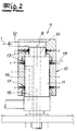
- the rotary distributor or media rotary distributor 9 is shown with its stationary element or the shaft 10 and the rotating element respectively its distributor head 11.
- the stationary element 10 has a rotationally symmetrical bore in comparison to a rotation axis R, within which the rotatable element 11 or the distributor head 11 equipped with a corresponding rotationally symmetrical jacket is received.
- a plurality of leads 12, 13 are provided at the periphery of the stationary element 10 .
- the product is fed to a channel 14, which runs predominantly in the longitudinal direction of the rotating element 11.
- the supply line 13 serves to supply cleaning liquid, which is also continued over a largely extending in the longitudinal direction of the rotating member 11 channel 15.
- further supply lines can be provided.
- a plurality of seals 17 are provided, which are in detail the subject of Fig. 3 are.
- the seals 17 in question are arranged between the stationary element or the shaft 10 and the rotating element or the distributor head 11 and ensure that the gap 16 present here is sealed.
- the seals 17 are provided between the supply lines 12, 13 and on the lower end face of the stationary element 10 and ensure that the fluid flowing through the illustrated media rotary distributor 9 fluids are separated from each other and the rotary distributor or media rotary distributor 9 is sealed to the outside.
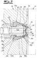
- the respective seal 17 is shown in the Fig. 3 arranged in a sealing chamber 18.
- the seal chamber 18 is designed to be split.
- the stationary part 10 of the media rotary distributor 9 is verifiable Fig. 3 divided and is composed of a part 10 a and a part 10 b, each extending above and below the sealing chamber 18.
- the two parts 10a, 10b of the stationary element 10 receive a support body 19a, 19b between them.
- the support body 19a, 19b is designed in two parts and is composed of a base body 19a and a sealing body 19b.
- the main body 19a is anchored in the stationary part 10.
- the two parts 10a and 10b of the stationary part 10 each have contact webs 20 which engage over a shoulder 21 on the support body 19a, 19b or its base body 19a.
- the support body 19a, 19b as well as the stationary element 10 is designed as a whole rotationally symmetrical compared to the common axis of rotation R.
- the contact webs 20 on the two parts 10a and 10b of the stationary element 10 engage in a groove 22 of the support body 19a, 19b, which connects the already mentioned and described base body 19a with the sealing body 19b.
- the sealing body 19b carries the seal 17, which is a hollow gasket 17 in the exemplary embodiment.
- the seal 17 surrounds the sealing body 19b and engages with plant shoulders 23 a respective undercut 24 of the sealing body 19b.
- the seal 17 experiences a perfect hold in the axial direction on the support body 19a, 19b.
- each subsequent to the abutment shoulders 23 of the seal 17 flanks 25 of the seal 17 between the seal body 19b of the support body 19a, 19b and the respective part 10a, 10b of the stationary element 10 are clamped.
- the support body 19a, 19b has a feed line 26 which in the present case passes through the support body 19a, 19b centrally. Since the support body 19a, 19b is topologically a support ring, it is usual to work with a plurality of supply lines 26 distributed over the circumference of the support ring in question, each of which is designed to communicate with a pressure source 27. That is, with the help of this pressure source 27 can be generated in the respective supply line 26, a positive pressure / negative pressure compared to the prevailing at the site of the vessel filling machine respectively the media rotary distributor 9 normal pressure.
- the seal 17 according to the invention can be acted upon by pressure.
- the seal 17 is designed as a hollow seal 17, one observes depending on their functional position a more or less pronounced cavity 28 which is formed between a head-side sealing portion 29 of the seal 17 on the one hand and a front side of the seal body 19b sealing surface 30 on the other.
- the head-side sealing portion 29 of the seal 17 is equipped with sealing lips 31 on both sides. Between the two sealing lips 31, the head-side sealing portion 29 of the seal 17 according to the embodiment is curved inward, in particular convexly curved inwards. That applies at least in the case that the Seal or hollow seal 17 is subjected to normal pressure. In this case, primarily the sealing lips 31 ensure the required sealing of the gap 16 between the stationary element 10 and the rotating element 11.
- the seal 17 retracts from the gap 16.
- the seal 17 is pressurized with normal pressure or overpressure, the seal or hollow seal 17 protrudes with respect to its seal chamber 18, as shown in the drawing Fig. 3 is shown.
- the seal 17 retracts into the sealing chamber 18 and the previously closed gap 16 is opened. This indicates a dot-dash representation.
- the supply of negative pressure from the pressure source 27 to the supply line 26 ensures that the sealing surfaces 29 on the one hand of the seal 17 and on the other hand the sealing surface 30 on the front side of the sealing body 19b abut each other.
- the two sealing surfaces 29, 30 each designed to correspond or adapted to each other. Since in the embodiment, the head-side sealing portion 29 of the seal 17 is largely convex inwardly curved, also has the corresponding sealing surface 30 front of the seal body 19b via a corresponding convex inwardly curved shape.
- side regions 32 of the head-side sealing section 29 of the seal 17 also engage associated contact surfaces 33 of the front-side sealing surface 30 on the sealing body 19b on.
- the side regions 32 of the seal 17 in each case adjoin the respective fixed flanks 25 on the front side.
- the described pressurization of the seal 17 merely causes the sealing section 29 to engage with the Both side portions 32 as described deformed and can deform.
- the head-side sealing portion 29 of the seal 17 applies to the corresponding sealing surface 30 of the support body 19a, 19b or is approached.
- the seal 17 defines, depending on the inside loading of the hollow chamber 28 with a positive pressure or negative pressure, a front projection Ü with respect to the sealing body 19b or the support body 19a, 19b overall. Then, the gap 16 is closed and the seal 17 protrudes from its sealing chamber 18 before and is at least with their sealing lips 31 on the rotating element 11 at. This applies by and large in the event that the seal 17 is subjected to normal pressure or overpressure.
- the cavity 28 disappears or is reduced to a minimum. Because the sealing portion 29 of the seal 17 applies to the sealing surface 30 of the support body 19 a, 19 b. At the same time the side portions 32 come into contact with the contact surfaces 33.
- the seal 17 is from its projecting position relative to the seal chamber 18 with the supernatant Ü in a contrast retracted position, in which the supernatant Ü is no longer observed. Now the gap 16 is open and can be rinsed with cleaning fluid, for example, which is supplied via the feed line 13 into the gap 16.
- sterile water is routinely passed through the gap 16 to remove any residual cleaning fluid.
- the pressure source 27 ensures that the seal 17 is subjected to a normal pressure and / or pressure.
- the sealing lips 31 abut the rotating element 11, any remaining sterile water still remaining in the gap 16 acting as a lubricant for the two sealing lips 31.
- the two parts 10a, 10b of the stationary element 10 are equipped at the outer edge of the sealing chamber 18 with a respective rounding 35 and otherwise the seal 17 or its two flanks 25 the gap between the support body 19a, 19b and the respective part 10a, 10b of the stationary part 10, a total flawless cleaning is observed, which predestined the described media rotary distributor 9 for aseptic applications. Because the gap 16 is not equipped with any fissures or dead spaces, but are found mostly smooth surfaces. In this way, a complete and dead space-free cleaning, which improves the media rotary distributor 9 for the described aseptic applications, succeeds.
- the pressure source 27 can also be equipped with a pressure gauge 36, which can also be integrated into the pressure source 27. With the help of the pressure gauge 36 can determine whether, for example, leaks in particular in the hollow chamber 28 and consequently the seal 17 are present. For this purpose, for example, measured values for the respectively applied overpressure / underpressure are stored in an associated control unit and compared with previous measured values or desired values. If significant deviations occur, this is an indication that leaks can be observed, which can be deduced, for example, from a porous seal 17.
- the seal 17 can be checked automatically for their functionality, without the media rotary distributor 9 is disassembled. It So finds a quasi-automatic and recurrent examination of the seal 17 on functionality instead. This is particularly necessary and particularly advantageous in view of the fact that the seal 17 is known to seal off the media to be conveyed via the media rotary distributor 9 and optionally deform from the outside as a result of associated pressure, as indicated by corresponding arrows in FIG Fig. 3 suggest. Any damage associated with this pressure can now be detected and identified with the aid of the pressure gauge 36.
- seal 17 consists of two individual seals so that between the two flanks 31 no comparable, connecting sealing element 29 is arranged.
- one or both sealing elements 17 or their free ends can be approximated or applied analogously to one or more sealing surfaces of a support body 19.
Landscapes
- Engineering & Computer Science (AREA)
- General Engineering & Computer Science (AREA)
- Physics & Mathematics (AREA)
- Architecture (AREA)
- Fluid Mechanics (AREA)
- Mechanical Engineering (AREA)
- Filling Of Jars Or Cans And Processes For Cleaning And Sealing Jars (AREA)
Priority Applications (1)
| Application Number | Priority Date | Filing Date | Title |
|---|---|---|---|
| PL14705710T PL2969895T3 (pl) | 2013-03-14 | 2014-02-14 | Obrotowy rozdzielacz mediów do napełniarek pojemników |
Applications Claiming Priority (2)
| Application Number | Priority Date | Filing Date | Title |
|---|---|---|---|
| DE102013102594.3A DE102013102594A1 (de) | 2013-03-14 | 2013-03-14 | Mediendrehverteiler für insbesondere Gefäßfüllmaschinen |
| PCT/EP2014/000412 WO2014139627A1 (de) | 2013-03-14 | 2014-02-14 | Mediendrehverteiler für gefässfüllmaschinen |
Publications (2)
| Publication Number | Publication Date |
|---|---|
| EP2969895A1 EP2969895A1 (de) | 2016-01-20 |
| EP2969895B1 true EP2969895B1 (de) | 2017-03-29 |
Family
ID=50151250
Family Applications (1)
| Application Number | Title | Priority Date | Filing Date |
|---|---|---|---|
| EP14705710.3A Active EP2969895B1 (de) | 2013-03-14 | 2014-02-14 | Mediendrehverteiler für gefässfüllmaschinen |
Country Status (4)
| Country | Link |
|---|---|
| EP (1) | EP2969895B1 (pl) |
| DE (1) | DE102013102594A1 (pl) |
| PL (1) | PL2969895T3 (pl) |
| WO (1) | WO2014139627A1 (pl) |
Families Citing this family (9)
| Publication number | Priority date | Publication date | Assignee | Title |
|---|---|---|---|---|
| EP3015416B1 (en) * | 2014-10-31 | 2016-12-28 | Sidel Participations S.A.S. | Manifold for a filling unit for filling a plurality of articles with a pourable product |
| DE102015118671A1 (de) * | 2015-10-30 | 2017-05-04 | Krones Ag | Vorrichtung zum Befüllen von Behältern mit einem Füllprodukt |
| ITUB20154964A1 (it) * | 2015-11-05 | 2017-05-05 | Zanichelli Mecc S P A | Macchina dosatrice a pistoni, particolarmente per il riempimento di contenitori. |
| DE102016107356A1 (de) * | 2016-04-20 | 2017-10-26 | Krones Ag | Vorrichtung und Verfahren zum Befüllen eines Behälters mit einem Füllprodukt |
| DE102016107355A1 (de) | 2016-04-20 | 2017-10-26 | Krones Ag | Vorrichtung zum Befüllen mindestens eines Behälters mit einem Füllprodukt in einer Getränkeabfüllanlage |
| US10919750B2 (en) * | 2017-06-06 | 2021-02-16 | Pacific Packaging Machinery, Llc | Rotary filling machine |
| CN115180583B (zh) * | 2022-07-25 | 2024-04-26 | 展一智能科技(苏州)有限公司 | 对包装桶进行开关盖的方法 |
| CN117585328B (zh) * | 2023-11-08 | 2026-04-10 | 展一智能科技(东台)有限公司 | 罐口密封连接锁紧方法 |
| DE102024104612A1 (de) * | 2024-02-20 | 2025-08-21 | Khs Gmbh | Vorrichtung zum Behandeln und/oder zum Transportieren von Behältern |
Family Cites Families (9)
| Publication number | Priority date | Publication date | Assignee | Title |
|---|---|---|---|---|
| DE877257C (de) * | 1943-06-20 | 1953-05-21 | Holstein & Kappert Maschf | Kolbenstangenabdichtung fuer Flaschenanpressvorrichtungen |
| US4844481A (en) * | 1988-04-04 | 1989-07-04 | Marchadour Jean Charles | Cylindrical seal system |
| CH679417A5 (pl) * | 1989-04-25 | 1992-02-14 | Erich Bertsch | |
| DE4326346A1 (de) | 1993-08-05 | 1995-02-09 | Khs Masch & Anlagenbau Ag | Verfahren zum sterilen Füllen von Flaschen, Dosen o. dgl. Behälter mit einem flüssigen Füllgut sowie Füller zum Durchführen dieses Verfahrens |
| US6035872A (en) * | 1995-11-14 | 2000-03-14 | Hans Werner Hees | Rotary distributor rotating apparatus for handling of objects, in particular containers, with a revolving joint for the transport of fluid between a stationary assembly and a rotating assembly |
| DE29620323U1 (de) | 1996-11-22 | 1997-01-23 | Krones Ag Hermann Kronseder Maschinenfabrik, 93073 Neutraubling | Drehverteiler für rotierende Gefäßfüllmaschinen |
| DE29808121U1 (de) * | 1998-05-06 | 1998-07-23 | NEM Power-Systems, Niederlassung Deutschland der NEM B.V. Niederlande, 45665 Recklinghausen | Klappe |
| US20050046114A1 (en) * | 2003-08-27 | 2005-03-03 | Bohner Stephan Ernst | Rotary seal member, assembly and methods for a hydraulic rotary swivel |
| DE202006000325U1 (de) | 2006-01-11 | 2006-03-16 | Krones Ag | Drehverteiler für Füller |
-
2013
- 2013-03-14 DE DE102013102594.3A patent/DE102013102594A1/de not_active Ceased
-
2014
- 2014-02-14 WO PCT/EP2014/000412 patent/WO2014139627A1/de not_active Ceased
- 2014-02-14 EP EP14705710.3A patent/EP2969895B1/de active Active
- 2014-02-14 PL PL14705710T patent/PL2969895T3/pl unknown
Also Published As
| Publication number | Publication date |
|---|---|
| PL2969895T3 (pl) | 2017-10-31 |
| EP2969895A1 (de) | 2016-01-20 |
| DE102013102594A1 (de) | 2014-09-18 |
| WO2014139627A1 (de) | 2014-09-18 |
Similar Documents
| Publication | Publication Date | Title |
|---|---|---|
| EP2969895B1 (de) | Mediendrehverteiler für gefässfüllmaschinen | |
| EP3074339B1 (de) | Füllelement sowie füllmaschine | |
| EP2751016B1 (de) | Hubelement mit ausfahrbarer spülhülse | |
| EP1464613B1 (de) | Spülbares Huborgan | |
| WO2014019642A1 (de) | Füllelement sowie füllmaschine | |
| DE102011111483A1 (de) | Behälterbehandlungsmaschine | |
| DE102013105221A1 (de) | Behälterbehandlungsmaschine sowie Verfahren zum Betrieb einer Behälterbehandlungsmaschine | |
| EP2328829B1 (de) | Behälterbehandlungsmachine, insbesondere verschliessmaschine | |
| EP3212934B1 (de) | Kolbenanordnung zum pumpen einer flüssigkeit | |
| EP3554987B1 (de) | Füllelementanordnung sowie füllmaschine | |
| EP2881360A1 (de) | Vorrichtung zum Behandeln eines Behälters in einer Getränkabfüllanlage und Verfahren zur Reinigung der Vorrichtung | |
| EP3331812B1 (de) | Verfahren zur reinigung und/oder desinfektion von verschliesselementen sowie verschliessmaschine | |
| EP3678985B1 (de) | Positioniervorrichtung zur relativpositionierung eines zu behandelnden behälters und einer behandlungseinrichtung in einer behälterbehandlungsanlage | |
| EP2844604A1 (de) | Hubvorrichtung für behälterbehandlungsmaschinen sowie behälterbehandlungsmaschine | |
| WO1997018154A1 (de) | Rotationsverteiler-rundläufereinrichtung zur behandlung von gegenständen, insbesondere von behältern, mit einer drehverbindung für den fluidentransport zwischen einer ständerbaugruppe und einer rotorbaugruppe | |
| EP2958850B1 (de) | Füllsystem | |
| WO2011095187A1 (de) | Verfahren sowie füllsystem zum druckfüllen von behältern | |
| DE29618998U1 (de) | Rotationsverteiler-Rundläufereinrichtung zur Behandlung von Gegenständen, insbesondere von Behältern, mit einer Drehverbindung für den Fluidentransport zwischen einer Ständerbaugruppe und einer Rotorbaugruppe | |
| DE9218509U1 (de) | Vorrichtung zum Behandeln von KEG, insbesondere zum Füllen von KEG | |
| DE102022129297A1 (de) | Vorrichtung und Verfahren zum Herstellen eines mit flüssigem Füllgut befüllten Behälters aus einem thermisch konditionierten Vorformling | |
| DE102013101812A1 (de) | Füllsystem sowie Füllmaschine | |
| DE9218480U1 (de) | Behandlungsstation für eine Vorrichtung zum Behandeln von KEG, insbesondere zum Reinigen oder Füllen von KEG | |
| DE102013101813A1 (de) | Füllsystem |
Legal Events
| Date | Code | Title | Description |
|---|---|---|---|
| PUAI | Public reference made under article 153(3) epc to a published international application that has entered the european phase |
Free format text: ORIGINAL CODE: 0009012 |
|
| 17P | Request for examination filed |
Effective date: 20151014 |
|
| AK | Designated contracting states |
Kind code of ref document: A1 Designated state(s): AL AT BE BG CH CY CZ DE DK EE ES FI FR GB GR HR HU IE IS IT LI LT LU LV MC MK MT NL NO PL PT RO RS SE SI SK SM TR |
|
| AX | Request for extension of the european patent |
Extension state: BA ME |
|
| DAX | Request for extension of the european patent (deleted) | ||
| GRAP | Despatch of communication of intention to grant a patent |
Free format text: ORIGINAL CODE: EPIDOSNIGR1 |
|
| INTG | Intention to grant announced |
Effective date: 20161125 |
|
| GRAS | Grant fee paid |
Free format text: ORIGINAL CODE: EPIDOSNIGR3 |
|
| GRAA | (expected) grant |
Free format text: ORIGINAL CODE: 0009210 |
|
| AK | Designated contracting states |
Kind code of ref document: B1 Designated state(s): AL AT BE BG CH CY CZ DE DK EE ES FI FR GB GR HR HU IE IS IT LI LT LU LV MC MK MT NL NO PL PT RO RS SE SI SK SM TR |
|
| REG | Reference to a national code |
Ref country code: GB Ref legal event code: FG4D Free format text: NOT ENGLISH |
|
| REG | Reference to a national code |
Ref country code: CH Ref legal event code: EP |
|
| REG | Reference to a national code |
Ref country code: AT Ref legal event code: REF Ref document number: 879565 Country of ref document: AT Kind code of ref document: T Effective date: 20170415 |
|
| REG | Reference to a national code |
Ref country code: NL Ref legal event code: FP Ref country code: IE Ref legal event code: FG4D Free format text: LANGUAGE OF EP DOCUMENT: GERMAN |
|
| REG | Reference to a national code |
Ref country code: DE Ref legal event code: R096 Ref document number: 502014003215 Country of ref document: DE |
|
| PG25 | Lapsed in a contracting state [announced via postgrant information from national office to epo] |
Ref country code: HR Free format text: LAPSE BECAUSE OF FAILURE TO SUBMIT A TRANSLATION OF THE DESCRIPTION OR TO PAY THE FEE WITHIN THE PRESCRIBED TIME-LIMIT Effective date: 20170329 Ref country code: GR Free format text: LAPSE BECAUSE OF FAILURE TO SUBMIT A TRANSLATION OF THE DESCRIPTION OR TO PAY THE FEE WITHIN THE PRESCRIBED TIME-LIMIT Effective date: 20170630 Ref country code: LT Free format text: LAPSE BECAUSE OF FAILURE TO SUBMIT A TRANSLATION OF THE DESCRIPTION OR TO PAY THE FEE WITHIN THE PRESCRIBED TIME-LIMIT Effective date: 20170329 Ref country code: FI Free format text: LAPSE BECAUSE OF FAILURE TO SUBMIT A TRANSLATION OF THE DESCRIPTION OR TO PAY THE FEE WITHIN THE PRESCRIBED TIME-LIMIT Effective date: 20170329 Ref country code: NO Free format text: LAPSE BECAUSE OF FAILURE TO SUBMIT A TRANSLATION OF THE DESCRIPTION OR TO PAY THE FEE WITHIN THE PRESCRIBED TIME-LIMIT Effective date: 20170629 |
|
| PG25 | Lapsed in a contracting state [announced via postgrant information from national office to epo] |
Ref country code: RS Free format text: LAPSE BECAUSE OF FAILURE TO SUBMIT A TRANSLATION OF THE DESCRIPTION OR TO PAY THE FEE WITHIN THE PRESCRIBED TIME-LIMIT Effective date: 20170329 Ref country code: LV Free format text: LAPSE BECAUSE OF FAILURE TO SUBMIT A TRANSLATION OF THE DESCRIPTION OR TO PAY THE FEE WITHIN THE PRESCRIBED TIME-LIMIT Effective date: 20170329 Ref country code: SE Free format text: LAPSE BECAUSE OF FAILURE TO SUBMIT A TRANSLATION OF THE DESCRIPTION OR TO PAY THE FEE WITHIN THE PRESCRIBED TIME-LIMIT Effective date: 20170329 Ref country code: BG Free format text: LAPSE BECAUSE OF FAILURE TO SUBMIT A TRANSLATION OF THE DESCRIPTION OR TO PAY THE FEE WITHIN THE PRESCRIBED TIME-LIMIT Effective date: 20170629 |
|
| PG25 | Lapsed in a contracting state [announced via postgrant information from national office to epo] |
Ref country code: RO Free format text: LAPSE BECAUSE OF FAILURE TO SUBMIT A TRANSLATION OF THE DESCRIPTION OR TO PAY THE FEE WITHIN THE PRESCRIBED TIME-LIMIT Effective date: 20170329 Ref country code: CZ Free format text: LAPSE BECAUSE OF FAILURE TO SUBMIT A TRANSLATION OF THE DESCRIPTION OR TO PAY THE FEE WITHIN THE PRESCRIBED TIME-LIMIT Effective date: 20170329 Ref country code: EE Free format text: LAPSE BECAUSE OF FAILURE TO SUBMIT A TRANSLATION OF THE DESCRIPTION OR TO PAY THE FEE WITHIN THE PRESCRIBED TIME-LIMIT Effective date: 20170329 Ref country code: SK Free format text: LAPSE BECAUSE OF FAILURE TO SUBMIT A TRANSLATION OF THE DESCRIPTION OR TO PAY THE FEE WITHIN THE PRESCRIBED TIME-LIMIT Effective date: 20170329 Ref country code: ES Free format text: LAPSE BECAUSE OF FAILURE TO SUBMIT A TRANSLATION OF THE DESCRIPTION OR TO PAY THE FEE WITHIN THE PRESCRIBED TIME-LIMIT Effective date: 20170329 |
|
| PG25 | Lapsed in a contracting state [announced via postgrant information from national office to epo] |
Ref country code: IS Free format text: LAPSE BECAUSE OF FAILURE TO SUBMIT A TRANSLATION OF THE DESCRIPTION OR TO PAY THE FEE WITHIN THE PRESCRIBED TIME-LIMIT Effective date: 20170729 Ref country code: SM Free format text: LAPSE BECAUSE OF FAILURE TO SUBMIT A TRANSLATION OF THE DESCRIPTION OR TO PAY THE FEE WITHIN THE PRESCRIBED TIME-LIMIT Effective date: 20170329 |
|
| REG | Reference to a national code |
Ref country code: DE Ref legal event code: R097 Ref document number: 502014003215 Country of ref document: DE |
|
| PG25 | Lapsed in a contracting state [announced via postgrant information from national office to epo] |
Ref country code: DK Free format text: LAPSE BECAUSE OF FAILURE TO SUBMIT A TRANSLATION OF THE DESCRIPTION OR TO PAY THE FEE WITHIN THE PRESCRIBED TIME-LIMIT Effective date: 20170329 |
|
| PLBE | No opposition filed within time limit |
Free format text: ORIGINAL CODE: 0009261 |
|
| STAA | Information on the status of an ep patent application or granted ep patent |
Free format text: STATUS: NO OPPOSITION FILED WITHIN TIME LIMIT |
|
| REG | Reference to a national code |
Ref country code: FR Ref legal event code: PLFP Year of fee payment: 5 |
|
| 26N | No opposition filed |
Effective date: 20180103 |
|
| PG25 | Lapsed in a contracting state [announced via postgrant information from national office to epo] |
Ref country code: SI Free format text: LAPSE BECAUSE OF FAILURE TO SUBMIT A TRANSLATION OF THE DESCRIPTION OR TO PAY THE FEE WITHIN THE PRESCRIBED TIME-LIMIT Effective date: 20170329 |
|
| REG | Reference to a national code |
Ref country code: CH Ref legal event code: PL |
|
| PG25 | Lapsed in a contracting state [announced via postgrant information from national office to epo] |
Ref country code: MC Free format text: LAPSE BECAUSE OF FAILURE TO SUBMIT A TRANSLATION OF THE DESCRIPTION OR TO PAY THE FEE WITHIN THE PRESCRIBED TIME-LIMIT Effective date: 20170329 Ref country code: MT Free format text: LAPSE BECAUSE OF FAILURE TO SUBMIT A TRANSLATION OF THE DESCRIPTION OR TO PAY THE FEE WITHIN THE PRESCRIBED TIME-LIMIT Effective date: 20170329 |
|
| GBPC | Gb: european patent ceased through non-payment of renewal fee |
Effective date: 20180214 |
|
| REG | Reference to a national code |
Ref country code: IE Ref legal event code: MM4A |
|
| REG | Reference to a national code |
Ref country code: BE Ref legal event code: MM Effective date: 20180228 |
|
| PG25 | Lapsed in a contracting state [announced via postgrant information from national office to epo] |
Ref country code: CH Free format text: LAPSE BECAUSE OF NON-PAYMENT OF DUE FEES Effective date: 20180228 Ref country code: LI Free format text: LAPSE BECAUSE OF NON-PAYMENT OF DUE FEES Effective date: 20180228 Ref country code: LU Free format text: LAPSE BECAUSE OF NON-PAYMENT OF DUE FEES Effective date: 20180214 |
|
| PG25 | Lapsed in a contracting state [announced via postgrant information from national office to epo] |
Ref country code: IE Free format text: LAPSE BECAUSE OF NON-PAYMENT OF DUE FEES Effective date: 20180214 |
|
| PG25 | Lapsed in a contracting state [announced via postgrant information from national office to epo] |
Ref country code: GB Free format text: LAPSE BECAUSE OF NON-PAYMENT OF DUE FEES Effective date: 20180214 Ref country code: BE Free format text: LAPSE BECAUSE OF NON-PAYMENT OF DUE FEES Effective date: 20180228 |
|
| PG25 | Lapsed in a contracting state [announced via postgrant information from national office to epo] |
Ref country code: TR Free format text: LAPSE BECAUSE OF FAILURE TO SUBMIT A TRANSLATION OF THE DESCRIPTION OR TO PAY THE FEE WITHIN THE PRESCRIBED TIME-LIMIT Effective date: 20170329 |
|
| REG | Reference to a national code |
Ref country code: AT Ref legal event code: MM01 Ref document number: 879565 Country of ref document: AT Kind code of ref document: T Effective date: 20190214 |
|
| PG25 | Lapsed in a contracting state [announced via postgrant information from national office to epo] |
Ref country code: AT Free format text: LAPSE BECAUSE OF NON-PAYMENT OF DUE FEES Effective date: 20190214 |
|
| PG25 | Lapsed in a contracting state [announced via postgrant information from national office to epo] |
Ref country code: PT Free format text: LAPSE BECAUSE OF FAILURE TO SUBMIT A TRANSLATION OF THE DESCRIPTION OR TO PAY THE FEE WITHIN THE PRESCRIBED TIME-LIMIT Effective date: 20170329 |
|
| PG25 | Lapsed in a contracting state [announced via postgrant information from national office to epo] |
Ref country code: CY Free format text: LAPSE BECAUSE OF FAILURE TO SUBMIT A TRANSLATION OF THE DESCRIPTION OR TO PAY THE FEE WITHIN THE PRESCRIBED TIME-LIMIT Effective date: 20170329 Ref country code: HU Free format text: LAPSE BECAUSE OF FAILURE TO SUBMIT A TRANSLATION OF THE DESCRIPTION OR TO PAY THE FEE WITHIN THE PRESCRIBED TIME-LIMIT; INVALID AB INITIO Effective date: 20140214 Ref country code: MK Free format text: LAPSE BECAUSE OF NON-PAYMENT OF DUE FEES Effective date: 20170329 |
|
| PG25 | Lapsed in a contracting state [announced via postgrant information from national office to epo] |
Ref country code: AL Free format text: LAPSE BECAUSE OF FAILURE TO SUBMIT A TRANSLATION OF THE DESCRIPTION OR TO PAY THE FEE WITHIN THE PRESCRIBED TIME-LIMIT Effective date: 20170329 |
|
| PGFP | Annual fee paid to national office [announced via postgrant information from national office to epo] |
Ref country code: PL Payment date: 20220203 Year of fee payment: 9 Ref country code: NL Payment date: 20220216 Year of fee payment: 9 |
|
| REG | Reference to a national code |
Ref country code: NL Ref legal event code: MM Effective date: 20230301 |
|
| PG25 | Lapsed in a contracting state [announced via postgrant information from national office to epo] |
Ref country code: NL Free format text: LAPSE BECAUSE OF NON-PAYMENT OF DUE FEES Effective date: 20230301 |
|
| PG25 | Lapsed in a contracting state [announced via postgrant information from national office to epo] |
Ref country code: PL Free format text: LAPSE BECAUSE OF NON-PAYMENT OF DUE FEES Effective date: 20230214 |
|
| PG25 | Lapsed in a contracting state [announced via postgrant information from national office to epo] |
Ref country code: PL Free format text: LAPSE BECAUSE OF NON-PAYMENT OF DUE FEES Effective date: 20230214 |
|
| P01 | Opt-out of the competence of the unified patent court (upc) registered |
Free format text: CASE NUMBER: UPC_APP_0014577_2969895/2025 Effective date: 20251125 |
|
| PGFP | Annual fee paid to national office [announced via postgrant information from national office to epo] |
Ref country code: DE Payment date: 20260218 Year of fee payment: 13 |
|
| PGFP | Annual fee paid to national office [announced via postgrant information from national office to epo] |
Ref country code: IT Payment date: 20260224 Year of fee payment: 13 |
|
| PGFP | Annual fee paid to national office [announced via postgrant information from national office to epo] |
Ref country code: FR Payment date: 20260218 Year of fee payment: 13 |