EP2961078B1 - Information processing apparatus, method of controlling the same, and storage medium - Google Patents
Information processing apparatus, method of controlling the same, and storage medium Download PDFInfo
- Publication number
- EP2961078B1 EP2961078B1 EP15001644.2A EP15001644A EP2961078B1 EP 2961078 B1 EP2961078 B1 EP 2961078B1 EP 15001644 A EP15001644 A EP 15001644A EP 2961078 B1 EP2961078 B1 EP 2961078B1
- Authority
- EP
- European Patent Office
- Prior art keywords
- information
- ssid
- tag
- access point
- identification information
- Prior art date
- Legal status (The legal status is an assumption and is not a legal conclusion. Google has not performed a legal analysis and makes no representation as to the accuracy of the status listed.)
- Active
Links
Images


Classifications
-
- H—ELECTRICITY
- H04—ELECTRIC COMMUNICATION TECHNIQUE
- H04W—WIRELESS COMMUNICATION NETWORKS
- H04W4/00—Services specially adapted for wireless communication networks; Facilities therefor
- H04W4/80—Services using short range communication, e.g. near-field communication [NFC], radio-frequency identification [RFID] or low energy communication
-
- H—ELECTRICITY
- H04—ELECTRIC COMMUNICATION TECHNIQUE
- H04N—PICTORIAL COMMUNICATION, e.g. TELEVISION
- H04N1/00—Scanning, transmission or reproduction of documents or the like, e.g. facsimile transmission; Details thereof
- H04N1/23—Reproducing arrangements
- H04N1/2307—Circuits or arrangements for the control thereof, e.g. using a programmed control device, according to a measured quantity
- H04N1/2338—Circuits or arrangements for the control thereof, e.g. using a programmed control device, according to a measured quantity according to user specified instructions, e.g. user selection of reproduction mode
-
- H—ELECTRICITY
- H04—ELECTRIC COMMUNICATION TECHNIQUE
- H04N—PICTORIAL COMMUNICATION, e.g. TELEVISION
- H04N1/00—Scanning, transmission or reproduction of documents or the like, e.g. facsimile transmission; Details thereof
- H04N1/00127—Connection or combination of a still picture apparatus with another apparatus, e.g. for storage, processing or transmission of still picture signals or of information associated with a still picture
- H04N1/00281—Connection or combination of a still picture apparatus with another apparatus, e.g. for storage, processing or transmission of still picture signals or of information associated with a still picture with a telecommunication apparatus, e.g. a switched network of teleprinters for the distribution of text-based information, a selective call terminal
- H04N1/00307—Connection or combination of a still picture apparatus with another apparatus, e.g. for storage, processing or transmission of still picture signals or of information associated with a still picture with a telecommunication apparatus, e.g. a switched network of teleprinters for the distribution of text-based information, a selective call terminal with a mobile telephone apparatus
-
- H—ELECTRICITY
- H04—ELECTRIC COMMUNICATION TECHNIQUE
- H04W—WIRELESS COMMUNICATION NETWORKS
- H04W12/00—Security arrangements; Authentication; Protecting privacy or anonymity
- H04W12/06—Authentication
- H04W12/068—Authentication using credential vaults, e.g. password manager applications or one time password [OTP] applications
-
- H—ELECTRICITY
- H04—ELECTRIC COMMUNICATION TECHNIQUE
- H04W—WIRELESS COMMUNICATION NETWORKS
- H04W48/00—Access restriction; Network selection; Access point selection
- H04W48/16—Discovering, processing access restriction or access information
-
- H—ELECTRICITY
- H04—ELECTRIC COMMUNICATION TECHNIQUE
- H04W—WIRELESS COMMUNICATION NETWORKS
- H04W52/00—Power management, e.g. TPC [Transmission Power Control], power saving or power classes
- H04W52/02—Power saving arrangements
- H04W52/0209—Power saving arrangements in terminal devices
- H04W52/0225—Power saving arrangements in terminal devices using monitoring of external events, e.g. the presence of a signal
- H04W52/0229—Power saving arrangements in terminal devices using monitoring of external events, e.g. the presence of a signal where the received signal is a wanted signal
-
- H—ELECTRICITY
- H04—ELECTRIC COMMUNICATION TECHNIQUE
- H04W—WIRELESS COMMUNICATION NETWORKS
- H04W76/00—Connection management
- H04W76/10—Connection setup
- H04W76/14—Direct-mode setup
-
- H—ELECTRICITY
- H04—ELECTRIC COMMUNICATION TECHNIQUE
- H04B—TRANSMISSION
- H04B5/00—Near-field transmission systems, e.g. inductive loop type
-
- H—ELECTRICITY
- H04—ELECTRIC COMMUNICATION TECHNIQUE
- H04W—WIRELESS COMMUNICATION NETWORKS
- H04W84/00—Network topologies
- H04W84/18—Self-organising networks, e.g. ad-hoc networks or sensor networks
-
- H—ELECTRICITY
- H04—ELECTRIC COMMUNICATION TECHNIQUE
- H04W—WIRELESS COMMUNICATION NETWORKS
- H04W88/00—Devices specially adapted for wireless communication networks, e.g. terminals, base stations or access point devices
- H04W88/08—Access point devices
Definitions
- the present invention relates to an information processing apparatus, a method of controlling the same, and a storage medium.
- NFC Near Field Communication
- IP address and MAC address device-identifying information
- mobile terminal capable of reading contents of the NFC tag and executing an application used to print images and documents.
- Japanese Patent Laid-Open No. 2013-157736 describes a method in which with an image being displayed by launching an application on such a mobile terminal, information is read from the NFC tag by touching the NFC tag of a printing apparatus with the mobile terminal and the image is printed by the printing apparatus by means of a handover using the information.
- connection information IP address and MAC address of the printing apparatus
- IP address and MAC address of the printing apparatus IP address and MAC address of the printing apparatus
- a portion such as a tag sticker (NFC sticker) which cannot communicate with a controller of the printing apparatus
- an input error might occur when a user enters connection information manually, and if connection information containing such an input error has been written into the NFC tag, there is a problem in that printing using the printing apparatus cannot be executed.
- US 2012/208461 A1 discloses a mobile device and method for performing a function using a short-range communication tag, wherein the mobile device inputs function-related information into a short-range communication tag and recognizes proximity to the short-range communication tag.
- An aspect of the present invention is to eliminate the above-mentioned problems which are found in the conventional technology.
- a feature of the present invention is to provide a technique which can prevent a user from inputting wrong information when information used in communication is written into a partner apparatus.
- the present invention in its first aspect provides an information processing apparatus as specified in claims 1 to 10.
- the present invention in its second aspect provides a method of controlling an information processing apparatus as specified in claims 11 to 20.
- the present invention in its third aspect provides a storage medium as specified in claim 21.
- FIG. 1A is a diagram for describing a configuration of a communication system according to a first embodiment of the present invention.
- the communication system includes a mobile terminal 100 such as a smartphone, a printing apparatus 110, an NFC (Near Field Communication) tag 111, and an access point 120.
- the printing apparatus 110 which is a multifunction peripheral equipped with, for example, a printing function, scanning function, and fax function, conducts wireless communication such as Wi-Fi with the access point 120.
- the communication between the access point 120 and printing apparatus 110 is not limited to wireless communication, and may be wire communication using a LAN cable or the like.
- the mobile terminal 100 is capable of conducting wireless communication such as Wi-Fi.
- the mobile terminal 100 When a user enters an SSID or a security key of the access point 120 into the mobile terminal 100, the mobile terminal 100 is connected to the access point 120 and allowed to communicate with the printing apparatus 110 through the access point 120. Also, the mobile terminal 100 can transmit a print job to the printing apparatus 110 and other apparatus (not shown) connected via the access point 120. When a print job is transmitted to the printing apparatus 110 from the mobile terminal 100, the printing apparatus 110 which receives the print job performs printing according to the print job.
- the mobile terminal 100 and printing apparatus 110 can conduct short range wireless communication such as NFC.
- the printing apparatus 110 is equipped with an NFC tag 111 (Near Field Communication tag) which stores connection information (an IP address, MAC address, model name of the printing apparatus 110 or the like) used to connect to the printing apparatus 110.
- NFC tag 111 Near Field Communication tag
- the mobile terminal 100 can read and obtain the connection information from the NFC tag 111 or write information into the NFC tag 111.
- the mobile terminal 100 and other mobile terminals can obtain the connection information stored in the NFC tag 111 of the printing apparatus 110 using NFC, and connect to the access point 120 based on the connection information.
- the switching of connection between the mobile terminal 100 and printing apparatus 110 to wireless communication such as Wi-Fi using information obtained by short range wireless communication such as NFC in this way is referred to as a handover.
- the handover provides the user of the mobile terminal 100 with the advantage of being able to save the user from entering information (the SSID and security key of the access point 120) used to connect to the access point 120 into the mobile terminal 100.
- FIG. 1B is a block diagram for describing a hardware configuration of the NFC tag 111 according to the first embodiment.
- An antenna 1111 is connected to a controller 1112.
- the electric power is supplied to the controller 1112 as operating power of the controller 1112.
- the antenna 1111 operates as an antenna for wireless communication with the short range wireless communication unit 208 of the mobile terminal 100.
- the controller 1112 communicates with the mobile terminal 100 via the antenna 1111 and reads and writes to a memory 1113 according to read/write commands given via the communication. In this way, information of the printing apparatus 110 including the IP address (described later) is written into the memory 1113, allowing the information to be notified, for example, to the mobile terminal 100 via the antenna 1111 as required.
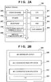
- FIG. 2A is a block diagram for describing a hardware configuration of the mobile terminal 100 according to the first embodiment.
- the mobile terminal 100 according to the first embodiment is assumed to be, for example, a smartphone, tablet PC, or the like, but the mobile terminal 100 may be any other information processing apparatus which can conduct wireless communication.
- a CPU 201 controls operation of the mobile terminal 100 by executing a program deployed in a RAM 203 from a ROM 202 or flash memory 204.
- the ROM 202 stores a control program, various setting data, and the like.
- a RAM 203 is used as a temporary storage area such as a main memory and a work area of the CPU 201.
- the flash memory 204 is used to store various data including photographs and electronic documents. Besides, the flash memory 204 stores an OS (operating system) and application programs such as an NFC writing application, NFC cooperative print application, and NFC cooperative scan application described later with reference to FIG. 2B .
- An operation panel 205 has a touch panel function capable of detecting touch actions of the user and displays various screens provided by application programs stored in the flash memory 204. The user can enter a desired operating command by touching the operation panel 205.
- the mobile terminal 100 is further equipped with hardware keys (not shown), and the user can enter operating commands into the mobile terminal 100 using the hardware keys.
- a speaker 206 and microphone 207 are used by the user to telephone another mobile terminal or a fixed-line phone.
- the short range wireless communication unit 208 conducts short range wireless communication such as NFC.
- the printing apparatus 110 is equipped with the NFC tag 111, and when the user brings the mobile terminal 100 close to the NFC tag 111 of the printing apparatus 110, short range wireless communication is established between the short range wireless communication unit 208 and the NFC tag 111 of the printing apparatus 110. With short range wireless communication being established, the short range wireless communication unit 208 can obtain and rewrite information of the NFC tag 111.
- a wireless communication unit 209 conducts wireless communication such as Wi-Fi. By transmitting a search packet via the wireless communication unit 209, the mobile terminal 100 can search for and find a printing apparatus capable of communicating via the access point 120. Also, with the mobile terminal 100, the use of handover allows the user to carry out wireless communication via the wireless communication unit 209 by a simple operation. Specifically, using the connection information (SSID and password of the access point 120) obtained from the NFC tag 111 of the printing apparatus 110 by the short range wireless communication unit 208, the wireless communication unit 209 can connect to the access point 120.
- connection information SSID and password of the access point 120
- FIG. 2B is a functional block diagram for describing a software configuration of the mobile terminal 100 according to the first embodiment.
- FIG. 2B is a block diagram of software functions implemented when the CPU 201 reads application programs stored in the ROM 202 or flash memory 204.
- An OS 223 is an operating system which controls basic operation of the mobile terminal 100.
- Various application programs can be installed on the mobile terminal 100, including three applications 220 to 222 described later.
- the OS 223 exchanges information with these application programs, and then according to instructions received from any of these application programs, the OS 223 displays a screen on the operation panel 205 or conducts wireless communication using the wireless communication unit 209.
- An NFC writing application 220 which is an application program installed on the mobile terminal 100, can write information needed to communicate with the printing apparatus 110 available via the access point 120 into the NFC tag 111.
- An NFC cooperative print application 221 which is an application program installed on the mobile terminal 100, performs a printing process by connecting to the printing apparatus 110 using information needed to communicate with the printing apparatus 110 and written into the NFC tag 111.
- An NFC cooperative scan application 222 which is an application program installed on the mobile terminal 100, can perform a scanning process by connecting to the printing apparatus 110 using the information needed to communicate with the printing apparatus 110 and written into the NFC tag 111. Note that in addition to the application programs described above, various application programs can be installed on the mobile terminal 100, but description thereof will be omitted.
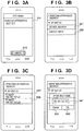
- FIGS. 3A to 3D and FIGS. 4A to 4B depict views illustrating examples of transition of screens displayed on the operation panel 205 when the NFC writing application 220 is executed on the mobile terminal 100 according to the first embodiment.
- FIG. 3A shows an example of a display brought up on the operation panel 205 when the NFC writing application 220 is launched on the mobile terminal 100.
- a display area 311 indicates that no printing apparatus is set.
- a Write button 312 is grayed out, indicating that the Write button 312 will not respond even if touched by the user.
- the screen shifts to a screen as shown in FIG. 3B .
- FIG. 3B shows an example of a screen used to specify whether to search for a printing apparatus by a device search or direct input, where the printing apparatus is a partner apparatus for communication.
- a device search is started and a screen as shown in FIG. 3C is displayed as a result of the device search.
- two printing apparatuses Print01 and Printer02
- apparatus information about the two printing apparatuses has been obtained and displayed.
- FIG. 3C shows an example of search results of a device search.
- Areas 331 and 332 display information about printing apparatuses found by the device search. In this example, the names and IP addresses of printers are displayed.
- the user touches either of the areas 331 and 332 on this screen information about the printing apparatus to be written into the NFC tag 111 is determined and the screen is transferred to the screen as shown in FIG. 4A .
- FIG. 3D shows an example of a screen used to enter an IP address or DNS name directly.
- the user enters an IP address or DNS name into an input box 341.
- FIG. 3D shows a state in which an IP address has been entered in the input box 341.
- the mobile terminal 100 verifies connection to the printing apparatus using the IP address, and obtains the name of the printing apparatus and IP address.
- the screen of the mobile terminal 100 transfers to the screen as shown in FIG. 4A .
- the mobile terminal 100 erases the screen and the screen of the mobile terminal 100 returns to the screen as shown in FIG. 3B .
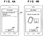
- FIG. 4A shows an example of a screen brought up on the operation panel 205 when the user touches the area 331 in FIG. 3C or when the user touches the OK button 343 in FIG. 3D .
- the user confirms the name and the IP address of the printing apparatus displayed in an area 351.
- the user touches a Write button 352 on this screen the screen is transferred to the screen as shown in FIG. 4B .
- the Write button 352 is displayed in normal, meaning that a user instruction for writing can be accepted.
- the screen of FIG. 4B is displayed when the name and the IP address of the printing apparatus confirmed in FIG. 4A are about to be written into the NFC tag 111.
- the short range wireless communication unit 208 is ready to write information into the NFC tag 111.
- the name and IP address of the printing apparatus 110 are written into the NFC tag 111.
- the name of the printing apparatus "Printer01”, IP address "192.167.127.22”, and MAC address are written.
- a Cancel button 361 is touched by the user to cancel writing into the NFC tag 111.
- FIG. 5 is a flowchart for describing processing of the mobile terminal 100 for writing into the NFC tag 111 of the printing apparatus 110 in the first embodiment. The steps of the flowchart are accomplished when the control program stored in the ROM 202 or flash memory 204 is executed under the control of the CPU 201.
- the CPU 201 determines in step S501 whether a printing apparatus search command has been issued by the user of the mobile terminal 100. Specifically, the CPU 201 determines whether or not the area 311 of the operation panel 205 is touched in FIG. 3A . If the area 311 is touched, the process advances to step S502 by determining that the printing apparatus search command has been issued, but if the area 311 is not touched, the process returns to step S501. In step S502, the CPU 201 displays the screen as shown in FIG. 3B on the operation panel 205 and waits until the user selects either a device search or direct input. Here, if the user touches the direct input area 322, the process advances to step S505, and if the user touches the device search area 321, the process advances to step S503.
- step S503 the CPU 201 searches for a printing apparatus ready to communicate via the access point 120 and displays results of the search, for example, as shown in FIG. 3C .
- the mobile terminal 100 transmits a packet by broadcasting and establishes an SNMP connection to the IP address of each printing apparatus which has responded to the packet.
- the CPU 201 obtains existence confirmation and a name of each printing apparatus (Printer01 and Printer02 in the example of FIG. 3C ) as well as an IP address and MAC address of each printing apparatus from the responses.
- step S504 the CPU 201 obtains the selection result of a printing apparatus selected by the user by touching the area 331 or 332 in FIG. 3C , and then the process advances to step S509.
- step S505 displays a screen as shown in FIG. 3D , on the operation panel 205, allowing the user to enter an IP address or DNS name.
- the CPU 201 obtains the IP address or host name entered by the user on the screen.
- step S506 the process advances to step S506 and conducts a connection confirmation test to test the connection to the IP address or DNS name and thereby determine whether or not the printing apparatus actually exists.
- the CPU 201 establishes an SNMP connection to the entered IP address or DNS name, obtains the existence confirmation of the apparatus as well as the name, IP address, and MAC address of the printing apparatus.
- step S507 where if the name and IP address of the printing apparatus have been obtained as a result of the connection confirmation test in step S506, the process advances to step S509, but if the connection has failed, the CPU 201 notifies the user of the connection failure in step S508 and then returns to step S502.
- a printing apparatus can be identified by the printing apparatus selection through the device search in steps S503 to S504, or by the direct input in steps S505 to S507.
- the CPU 201 displays a screen as shown in FIG. 4A , on the operation panel 205 in step S509.
- step S509 the CPU 201 determines whether or not the user has touched the Write button 352 of FIG. 4A , entering a command for writing information into the NFC tag 111.
- the process advances to step S510, but if there is no writing command, the process returns to step S509.
- step S510 the CPU 201 performs a preparation process for writing into the NFC tag 111. Specifically, the CPU 201 converts the IP address and the name of the printing apparatus 110 obtained by the device search or direct input into a format of the NFC tag 111 and holds the resulting data in the RAM 203. Then, the CPU 201 switches the display on the operation panel 205 to a screen as shown in FIG. 4B , prompting the user to touch the NFC tag 111 with the mobile terminal 100 to write the information into the NFC tag 111.
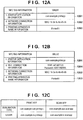
- FIG. 12A is a diagram showing an example of the data format created in step S510 and used to write information into the NFC tag 111.
- Reference numeral 1201 denotes startup application information which describes a name of an application to be launched when the NFC tag 111 is touched by the mobile terminal 100.
- the startup application information indicates that an NFC cooperative print application named "com.example.printapp" is launched.
- Reference numeral 1202 denotes a record of a MAC address which is network connection information. This is the MAC address of a searched printing apparatus. Although only the MAC address is described in FIG. 12A , a combination of information such as the IP address and UUID which can distinguish the printing apparatus 110 may be used instead.
- Reference numeral 1203 denotes a record for storing a device name. The record stores "Printer01" which is the name of the searched printing apparatus.
- step S511 the CPU 201 determines whether the user has brought the mobile terminal 100 close to the NFC tag 111 and touched the NFC tag 111 with the mobile terminal 100. If the NFC tag 111 has not been touched, the process returns to step S511, but if the NFC tag 111 has been touched, the process advances to step S512.
- step S512 the CPU 201 writes the information created in step S510 into the NFC tag 111 via the short range wireless communication unit 208. Then, in step S513, the CPU 201 determines whether or not the writing into the NFC tag 111 has been successful.
- step S514 the CPU 201 notifies the user of the successful writing by voice using, for example, the speaker 206 and/or by a display (not shown) provided on the operation panel 205, indicating the success.
- the CPU 201 finishes the process.
- step S513 the process advances to step S515, and the CPU 201 notifies the user that the writing into the NFC tag 111 has failed by voice using, for example, the speaker 206 and/or by a display (not shown) presented on the operation panel 205, indicating the failure. Then, the process returns to step S511.
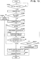
- FIG. 13 is a flowchart for describing processing of the mobile terminal 100 according to the first embodiment, in which the mobile terminal 100 reads the NFC tag 111 of the printing apparatus 110 and makes the printing apparatus 110 perform printing. Note that the steps of the flowchart are accomplished by execution of the control program stored in the ROM 202 or flash memory 204 under the control of the CPU 201.
- the CPU 201 determines in step S1301 whether the short range wireless communication unit 208 has detected that the user has touched the NFC tag 111 of the printing apparatus 110 with the mobile terminal 100. If it is determined here that the user has touched the NFC tag 111 with the mobile terminal 100, the process advances to step S1302. Otherwise, the CPU 201 carries out step S1301. In step S1302, using the short range wireless communication unit 208, the CPU 201 reads the data recorded in the NFC tag 111. Here, the mobile terminal 100 obtains the IP address and MAC address of the printing apparatus 110 stored in the NFC tag 111. Next, in step S1303, the CPU 201 determines whether or not the format of the data read in step S1302 is normal.
- step S1304 the CPU 201 provides an error indication (not shown) on the operation panel 205 and notifies the user of the failure to read the NFC tag 111 and thereby finishes the process.
- step S1303 determines whether data has been read from the NFC tag 111 successfully and that the format of the data is normal. If it is determined in step S1303 that data has been read from the NFC tag 111 successfully and that the format of the data is normal, the CPU 201 advances the process to step S1305.
- step S1305 to check whether the printing apparatus corresponding to the obtained IP address really exists, the CPU 201 causes the wireless communication unit 209 to make an inquiry about the printing apparatus via the access point 120 using a broadcast packet. This is carried out in a manner similar to the process of step S506 in FIG. 5 .
- step S1306 the CPU 201 determines whether or not the printing apparatus corresponding to the IP address obtained in step S1302 really exists.
- the CPU 201 identifies the printing apparatus in step S1310, and then transmits a print job to the IP address of the printing apparatus in step S1311 in order for printing to be done. In this case, the MAC address is not used.
- step S1306 determines whether the printing apparatus corresponding to the IP address does not exist.
- the CPU 201 advances the process to step S1307.
- step S1307 to check whether the printing apparatus really exists, the CPU 201 causes the wireless communication unit 209 to make an inquiry about the printing apparatus via the access point 120 using a broadcast packet.
- step S1308 the CPU 201 receives a response packet (response) from the printing apparatus via the wireless communication unit 209, inquires of the printing apparatus the MAC address of the printing apparatus using SNMP, and receives a response from the printing apparatus.
- the response to the inquiry packet contains the MAC address and IP address. Note that although the CPU 201 obtains the MAC address of the printing apparatus via SNMP in step S1308, the CPU 201 may obtain the MAC address by searching a MAC address table (ARP table) of the OS 223.
- ARP table MAC address table
- step S1309 the CPU 201 compares the MAC address stored in the NFC tag 111 read in step S1302 with the MAC address obtained in step S1308. If the MAC addresses match, the CPU 201 advances the process to step S1310, and if the MAC addresses do not match, the process advances to step S1312 to determine whether or not a time-out has occurred. Note that if the MAC address obtained from the NFC tag does not match the MAC address in the response packet, it is conceivable that the printing apparatus having the NFC tag has been powered off.
- step S1310 the CPU 201 identifies the IP address of the printing apparatus which has transmitted the response packet in step S1308 as that of the printing apparatus 110 with the NFC tag 111 attached thereto and sets the IP address as that of the printing apparatus which will carry out printing. Then, in step S1311, the CPU 201 transmits print data to the printing apparatus 110 of the IP address determined in step S1310 and thereby performs a printing process. Specifically, the CPU 201 transmits a file (image data) selected by the user via the operation panel 205 to the printing apparatus 110 having the IP address determined in step S1308, makes the printing apparatus 110 perform printing, and then finishes the process when the printing is finished.
- a file image data
- step S1312 the CPU 201 counts an elapsed time from step S1307 and if a time period equal to or longer than a predetermined time period (e.g., 10 seconds or more) elapses, the CPU 201 advances the process to step S1313 as a time-out.
- step S1313 the CPU 201 provides an error indication (not shown) on the operation panel 205, informing the user that the printing apparatus written into the NFC tag 111 was not able to be found and thereby finishes the process.
- the CPU 201 determines that the time-out does not occur in step S1312, the process returns to step S1308.
- the first embodiment by writing into the NFC tag of a printing apparatus only when connection to the printing apparatus is confirmed, it is possible to prevent wrong printing apparatus information from being written into the NFC tag. Also, by simply touching the NFC tag with the mobile terminal, a communication connection to the printing apparatus can be set easily and a printing process can be performed easily using the printing apparatus. Note that in the first embodiment, a target printing apparatus is searched for first using the IP address. This is because a shorter time is required for processing than in a case that MAC addresses are compared. Thus, by searching for a printing apparatus first through determination as to whether IP addresses match, it is possible to reduce the time required to transmit a print job and perform printing.
- connection information about wireless communication Wi-Fi
- description will be given of an example in which connection information about wireless communication (Wi-Fi) is also written into the NFC tag 111 in addition to the configuration described above.
- Wi-Fi wireless communication
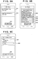
- FIGS. 6A to 6C , FIGS. 7A to 7C , and FIGS. 8A to 8C depict views illustrating examples of transition of screens displayed on the operation panel 205 when the NFC writing application 220 is executed on the mobile terminal 100 according to the second embodiment. Operation of the NFC writing application 220 will be described in detail later with reference to a flowchart of FIG. 9 . Note that the writing screen of FIG. 4B in common with the first embodiment is omitted in FIG. 6A to FIG. 8C by so noting.
- FIG. 6A depicts a view showing an example of a screen displayed on the operation panel 205 when the mobile terminal 100 according to the second embodiment is started.
- a Wi-Fi connection display area 611 and a printing apparatus display area 612 are displayed, both are not set. Also, a Write button 613 is grayed out, indicating that the Write button 613 will not respond even if touched by a user. Now, if the user touches the Wi-Fi connection display area 611, the screen shifts to a screen as shown in FIG. 6B .
- FIG. 6B depicts a view illustrating an example of a screen used to select how to set Wi-Fi connection information.
- a button 622 is designated to write NFC tag information shown in FIG. 12A in a manner similar to the first embodiment without specifying an SSID. That is, only the startup application information 1201, network connection information 1202, and printing apparatus name information 1203 are written into the NFC tag.
- a button 623 is designated to specify the use of an SSID for currently connected wireless communication.
- a button 624 is designated to display a list of access points currently available for connection and selecting a wireless connection.
- a button 625 is designated to specify manual input of an SSID by the user.
- FIG. 6C depicts a view illustrating an example of a screen displayed when the user touches the button 623 on the screen of FIG. 6B .
- "AP-NRT-01" which is the SSID of the access point 120 connected currently is displayed automatically in an area 631.
- FIG. 6C also shows that the user is entering a password in a password input field 632.
- the screen shifts to the screen as shown in FIG. 7A .
- the SSID is obtained from internal information of the mobile terminal 100
- the password is entered by the user because password information cannot be obtained for the security.
- FIG. 7A depicts a view illustrating an example of a connection test screen for wireless communication based on the SSID and password entered on the screen of FIG. 6C .
- a message and graphics are displayed here, indicating that a connection test is going on. If connection is verified here, the screen shifts to a screen as shown in FIG. 7B .
- the screen shifts to the screen of FIG. 7C .
- FIG. 7C depicts a view illustrating an example of a state in which establishment of communication has been confirmed by a wireless connection test via the access point 120.
- an area 702 displays the SSID "AP-NRT-01" of the access point 120 confirmed for communication by the wireless connection test.
- an area 703 displays status in which the printing apparatus is not set.
- the screen is transferred to the printing apparatus search screen as shown in FIG. 3B described above. Subsequently, a printing apparatus to be used for printing is searched for in a manner similar to the first embodiment described above.
- FIG. 8A depicts a view illustrating an example of a screen displayed when the search for a printing apparatus has been finished as a result of operations in FIG. 3B to FIG. 3D . That is, when the user chooses to set a printing apparatus by touching the area 703 on the screen of FIG. 7C , the screen is transferred to the screen as shown in FIG. 3B and allowed to set a printing apparatus in the manner described above with reference to FIGS. 3A to 3D and FIGS. 4A and 4B . Then, if the user touches the Write button 613 on the screen of FIG. 8A , the screen shifts to the writing screen as shown in FIG. 4B to write into the NFC tag 111.
- FIG. 8B depicts a view illustrating an example of a screen displaying a list of access points currently available for connection when the user touches the Wi-Fi Select button 624 on the screen of FIG. 6B .
- the screen is transferred to the screen as shown in FIG. 6C and asked to enter a password.
- FIG. 8C depicts a view illustrating an example of a screen displayed when the user touches the Manual Input button 625 on the screen of FIG. 6B .
- the user enters "AP-NRT-secret-01" into an SSID input area 804 and then enters a password into a password input area 805.
- the user touches a Connection Test button 806 the screen is transferred to the screen of FIG. 7A and a connection test is carried out as described above.
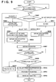
- FIG. 9 is a flowchart for describing processing of the mobile terminal 100 according to the second embodiment, in which the mobile terminal 100 searches for a printing apparatus by radio and writes connection information into the NFC tag 111 of the printing apparatus 110.
- the steps of the flowchart are accomplished when the CPU 201 executes the control program stored in the ROM 202 or flash memory 204.
- This process involves the process of preparing setting information for wireless communication additionally as a process performed before the printing apparatus selection process (steps S502 to S509) and a data writing into the NFC tag (steps S511 to S515) in FIG. 5 described above.
- step S901 the CPU 201 waits until the user of the mobile terminal 100 selects how to set Wi-Fi connection information on the screen of FIG. 6A . Specifically, the CPU 201 determines whether or not the user has touched the Wi-Fi connection display area 611 on the screen of FIG. 6A . If the user has touched the Wi-Fi connection display area 611, the CPU 201 advances the process to step S902, but otherwise, the process returns to step S901. In step S902, the CPU 201 displays, for example, the screen as shown in FIG. 6B , and the process branches to an appropriate step according to a selection made by the user of the mobile terminal 100 on the screen of FIG. 6B . If the user touches the button 622 on the screen of FIG.
- step S911 the CPU 201 stores information in the RAM 203, indicating that no SSID will be written, and the process advances to step S912. Then, in step S913, the CPU 201 uses the stored information in preparation for writing. Thus, in this case, NFC tag information which does not contain an SSID is generated.
- step S903 obtains the SSID from the currently connected wireless communication unit 209, and then the process advances to step S907.
- step S904 the CPU 201 advances the process to step S904, and displays a list of access points currently available for connection, for example, as shown in FIG. 8B .
- step S904 the CPU 201 displays a list of access points available for connection by obtaining a list of SSIDs currently available for connection from the wireless communication unit 209 so that the user is able to select any one of the displayed SSIDs.
- step S905 the CPU 201 obtains the SSID selected by a user operation and advances the process to a password input process in step S907.
- step S902 If the user touches the Manual Input button 625 in step S902, the CPU 201 advances the process to step S906, displays a screen shown, for example, in FIG. 8C , and obtains the SSID entered by the user manually via the screen, and then the process advances to step S907.
- step S907 the CPU 201 displays, for example, the screen of FIG. 6C or FIG. 8C and obtains the password entered by the user via the screen. Then, in step S908, the CPU 201 waits until the user touches the Connection Test button 633 or 806 of FIG. 6C or FIG. 8C , and if the user touches the Connection Test button, the CPU 201 advances the process to step S909 to carry out a connection test.
- step S912 the CPU 201 advances the process to step S912 and enables writing into the NFC tag 111, but if the connection is unsuccessful, the CPU 201 advances the process to step S910 to disable writing into the NFC tag 111 and notify the user of the connection failure, and then the process returns to step S902.
- step S912 the CPU 201 performs a printing apparatus selection process. This process is identical with the process of step S501 to step S509 in FIG. 5 described in the first embodiment. Thus, detailed description will be omitted here.
- the CPU 201 stores apparatus information about the selected printing apparatus.
- step S913 the CPU 201 performs a preparation process for writing data into the NFC tag 111. Specifically, the SSID setting made in steps S902 to S911 as well as the MAC address (or IP address) and name of the printing apparatus 110 obtained in step S912 are converted into the format (NDEF) of the NFC tag and held in the RAM 203. Then, the CPU 201 switches an operation screen to the writing status screen of FIG. 4B and advances the process to step S914.
- step S913 the format written into the NFC tag created in step S913 will be described. If it is determined in step S911 not to use any SSID, the same format as that in FIG. 12A of the first embodiment is used. On the other hand, if the user selects any one of the buttons 623 to 625 on the screen of FIG. 6B in step S902, the format shown in FIG. 12B is used.
- startup application information 1201, network connection information 1202, and printing apparatus name information 1203 are the same as the respective records in FIG. 12A of the first embodiment described above.
- Wi-Fi connection information 1204 has been added in FIG. 12B , where the Wi-Fi connection information 1204 includes SSID and password information about the access point 120 ready to be connected to the printing apparatus 110.
- step S914 the CPU 201 writes information into the NFC tag 111.
- This process is the same as the process of step S511 to step S515 according to the first embodiment. Thus, detailed description will be omitted here.
- the writing into the NFC tag 111 in step S914 finishes, the writing into the NFC tag 111 is completed.
- writing into the NFC tag 111 is performed only when connection to the access point 120 and connection to the printing apparatus 110 are confirmed. This makes it possible to prevent wrong information from being written into the NFC tag 111, including wrong SSID and password information about the access point 120 and wrong information about the printing apparatus 110. Also, as NFC tag information, connection information including the SSID and password for wireless connection can be recorded.
- a printing apparatus is determined on the screen as shown in FIG. 4A according to the first embodiment.
- destination information about a wireless communication network is determined through the operation in FIG. 6B and subsequent operations and written into the NFC tag 111.
- description will be given of a case in which information about a printing method and startup application is also written into the NFC tag 111 in addition to the configuration described above.
- the configuration of the communication system and hardware configuration of the mobile terminal 100 are similar to those of the first embodiment described above, and thus description thereof will be omitted.
- the reason why the user is made to select a printing method and startup application is that a compatible application differs depending on whether the printing apparatus is a sublimation type or a laser type and it is, therefore, necessary to change the startup application information 1201 of FIG. 12B written into the NFC tag 111.
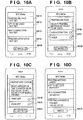
- FIGS. 10A to 10D depict views showing examples of a screen displayed on the operation panel 205 of the mobile terminal 100 according to the third embodiment.
- the examples shown here involve the operation of deciding a printing method, an application to be used for printing, and wireless communication connection information, searching for a printing apparatus, and thereby writing into the NFC tag 111.
- the operation of the NFC writing application will be described in detail later with reference to a flowchart of FIG. 11 . Note that setting screens in common with the first or second embodiment described above are omitted in FIGS. 10A to 10D by so noting.
- FIG. 10A shows a view illustrating an example of a screen displayed on the operation panel 205 when the mobile terminal 100 according to the third embodiment is started. None of a Printing Method area 1011, App To Be Used area 1012, Wi-Fi Connection display area 1013, and Printing Apparatus setting area 1014 is set yet. Also, a Write button 1015 is grayed out, indicating that the Write button 1015 will not respond even if touched by the user. Now, if the user touches the Printing Method area 1011, the screen shifts to the screen of FIG. 10B .
- FIG. 10B shows a view illustrating an example of a screen which allows the user to select a printing method.
- Buttons 1016 and 1017 are used to select a sublimation type and laser type printers, respectively, as printing methods of the printing apparatus 110. Now, if the user touches either of the buttons 1016 and 1017, the screen is transferred to the screen a shown in FIG. 10C .
- FIG. 10C shows a view illustrating an example of a screen used to select a startup application. Buttons 1018 and 1019 are used to select a print application and scan application, respectively, for the printing apparatus 110. If the user touches either of the buttons 1018 and 1019, the screen shifts to a Wi-Fi connection selection screen of FIG. 6B .
- FIG. 10D shows a view illustrating an example of a screen in which a printing method and startup application has been selected in FIGS. 10B to 10C , wireless communication settings are completed by the operations described with reference to FIGS. 6A to 8C , and the search for printing apparatus is finished by the operations of FIGS. 3B to 3D .
- the user touches the Write button 1015 the screen is transferred to the writing screen as shown in FIG. 4B .
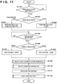
- FIG. 11 is a flowchart for describing processing of the mobile terminal 100 according to the third embodiment. This process additionally involves the process of selecting a printing method and startup application as a process performed before the selection of wireless communication settings (steps S901 to S911) in FIG. 9 , the selection of a printing apparatus (steps S502 to S509), and writing into the NFC tag (steps S511 to S515) in FIG. 5 .
- the steps of the flowchart are accomplished when the control program stored in the ROM 202 or flash memory 204 is executed under the control of the CPU 201.
- step S1101 the CPU 201 determines whether or not the user of the mobile terminal 100 has taken action to select a printing method. Specifically, the CPU 201 determines whether or not the user has touched the Printing Method area 1011 in FIG. 10A . If the user has taken action to select the printing method, the CPU 201 advances the process to step S1102. Otherwise, the process returns to step S1101. In step S1102, the CPU 201 displays, for example, the screen as shown in FIG. 10B and branches the process depending on the button touched by the user of the mobile terminal 100.
- step S1103 if the user touches the Sublimation button 1016 in step S1102, the CPU 201 advances the process to step S1103, stores the printing method as Sublimation in the RAM 203, and then the process advances to step S1105.
- the CPU 201 advances the process to step S1104, stores the printing method as Laser in the RAM 203, and then the process advances to step S1105.
- step S1105 the CPU 201 displays, for example, the screen as shown in FIG. 10C and waits until the user of the mobile terminal 100 takes action to select an application. If the user takes action to select an application, the process advances to step S1106 and the CPU 201 determines the application selected by the user. If it is determined in step S1106 that the user has selected the Print App button 1018, the CPU 201 advances the process to step S1107, stores a print application as the startup application in the RAM 203, and then the process advances to step S1109.
- step S1106 determines whether the user has selected the Scan App button 1019. If it is determined in step S1106 that the user has selected the Scan App button 1019, the CPU 201 advances the process to step S1108, stores a scan application including a print operation as the startup application in the RAM 203, and then the process advances to step S1109.
- step S1109 the CPU 201 performs the process of selecting a Wi-Fi connection information. This process is the same as the process of steps S901 to S911 in FIG. 9 according to the second embodiment described above, and thus description thereof will be omitted here.
- step S1110 the CPU 201 performs the process of selecting a printing apparatus. This process is the same as the process of steps S501 to S509 in FIG. 5 according to the first embodiment described above, and thus description thereof will be omitted.
- step S1111 the CPU 201 performs a preparation process for writing information into the NFC tag 111. Specifically, the CPU 201 obtains the information about the printing method determined in step S1103 or step S1104 and the startup application determined in step S1107 or S1108. Furthermore, the SSID setting made in steps S902 to S911 and the MAC address (or IP address) and the name of the printing apparatus 110 obtained in step S912 are converted into the format of the NFC tag 111 and held in the RAM 203.
- the format written into the NFC tag is the same format as that in FIG. 12B of the second embodiment.
- information about the application to be launched changes depending on the printing method and startup application, and thus CPU 201 determines the NFC tag format by determining the starting application name with reference to a table, as shown in FIG. 12C , held in the ROM 202.
- startup applications are registered by being associated with a printing method and a print/scan application.
- step S1112 the CPU 201 switches the operation screen to the writing status screen of FIG. 4B , where if the NFC tag 111 of the printing apparatus 110 is touched by the mobile terminal 100, the CPU 201 writes the information prepared in step S1111 into the NFC tag 111.
- This process is the same as the process of steps S511 to S515 according to the first embodiment, and thus detailed description thereof will be omitted. In this way, the writing into the NFC tag 111 is completed.
- writing into the NFC tag of a printing apparatus is performed only in a case that the printing method of the printing apparatus, startup application, connection to an access point, and connection to the printing apparatus are confirmed. This makes it possible to prevent wrong information from being written into the NFC tag, including a wrong startup application, wrong SSID and wrong password information about the access point, and wrong printing apparatus information.
- Embodiments of the present invention can also be realized by a computer of a system or apparatus that reads out and executes computer executable instructions (e.g., one or more programs) recorded on a storage medium (which may also be referred to more fully as a 'non-transitory computer-readable storage medium') to perform the functions of one or more of the above-described embodiment(s) and/or that includes one or more circuits (e.g., application specific integrated circuit (ASIC)) for performing the functions of one or more of the above-described embodiment(s), and by a method performed by the computer of the system or apparatus by, for example, reading out and executing the computer executable instructions from the storage medium to perform the functions of one or more of the above-described embodiment(s) and/or controlling the one or more circuits to perform the functions of one or more of the above-described embodiment(s).
- computer executable instructions e.g., one or more programs
- a storage medium which may also be referred to more fully as a '
- the computer may comprise one or more processors (e.g., central processing unit (CPU), micro processing unit (MPU)) and may include a network of separate computers or separate processors to read out and execute the computer executable instructions.
- the computer executable instructions may be provided to the computer, for example, from a network or the storage medium.
- the storage medium may include, for example, one or more of a hard disk, a random-access memory (RAM), a read only memory (ROM), a storage of distributed computing systems, an optical disk (such as a compact disc (CD), digital versatile disc (DVD), or Blu-ray Disc (BD)TM), a flash memory device, a memory card, and the like.
Applications Claiming Priority (1)
| Application Number | Priority Date | Filing Date | Title |
|---|---|---|---|
| JP2014130688A JP6071949B2 (ja) | 2014-06-25 | 2014-06-25 | 情報処理装置、その制御方法、及びプログラム |
Publications (2)
| Publication Number | Publication Date |
|---|---|
| EP2961078A1 EP2961078A1 (en) | 2015-12-30 |
| EP2961078B1 true EP2961078B1 (en) | 2018-03-14 |
Family
ID=53396122
Family Applications (1)
| Application Number | Title | Priority Date | Filing Date |
|---|---|---|---|
| EP15001644.2A Active EP2961078B1 (en) | 2014-06-25 | 2015-06-02 | Information processing apparatus, method of controlling the same, and storage medium |
Country Status (5)
| Country | Link |
|---|---|
| US (3) | US9693177B2 (ja) |
| EP (1) | EP2961078B1 (ja) |
| JP (1) | JP6071949B2 (ja) |
| KR (1) | KR101830201B1 (ja) |
| CN (1) | CN105282361B (ja) |
Families Citing this family (33)
| Publication number | Priority date | Publication date | Assignee | Title |
|---|---|---|---|---|
| JP6008617B2 (ja) * | 2012-06-29 | 2016-10-19 | キヤノン株式会社 | 通信装置およびその制御方法、並びにプログラム |
| WO2015136671A1 (ja) * | 2014-03-13 | 2015-09-17 | 富士機械製造株式会社 | 作業機用表示装置 |
| JP6302399B2 (ja) | 2014-11-17 | 2018-03-28 | キヤノン株式会社 | 近距離無線通信部を備える画像形成装置、その制御方法、及びプログラム |
| DE102014118290A1 (de) * | 2014-12-10 | 2016-06-16 | Océ Printing Systems GmbH & Co. KG | Verfahren zum Konfigurieren einer Steuerungseinrichtung für ein Produktionssystem und ein solches Produktionssystem |
| JP6558134B2 (ja) * | 2015-08-05 | 2019-08-14 | ブラザー工業株式会社 | 通信機器、及び、通信機器のためのコンピュータプログラム |
| JP6240125B2 (ja) | 2015-08-10 | 2017-11-29 | キヤノン株式会社 | 情報処理装置と情報処理装置を制御するプログラム、及びその制御方法 |
| JP6314951B2 (ja) * | 2015-10-08 | 2018-04-25 | コニカミノルタ株式会社 | 画像形成システムおよびプログラム |
| JP6887748B2 (ja) * | 2015-12-11 | 2021-06-16 | キヤノン株式会社 | データ送信装置、データ送信方法及びプログラム |
| JP6184580B1 (ja) * | 2016-01-29 | 2017-08-23 | キヤノン株式会社 | 情報処理装置、制御方法およびプログラム |
| JP6623872B2 (ja) * | 2016-03-18 | 2019-12-25 | 富士ゼロックス株式会社 | 情報処理装置、画像形成装置及び情報処理プログラム |
| JP6619682B2 (ja) | 2016-03-31 | 2019-12-11 | キヤノン株式会社 | 情報処理装置、制御方法およびプログラム |
| JP6772566B2 (ja) * | 2016-06-06 | 2020-10-21 | 富士ゼロックス株式会社 | 情報処理装置及びプログラム |
| JP2018013951A (ja) * | 2016-07-21 | 2018-01-25 | 京セラドキュメントソリューションズ株式会社 | 電子機器及び情報更新プログラム |
| CN106530393B (zh) * | 2016-11-07 | 2019-04-19 | 广东电网有限责任公司佛山供电局 | 一种新型标示牌制作方法及装置 |
| CN106572433A (zh) * | 2016-11-12 | 2017-04-19 | 江苏速度信息科技股份有限公司 | 基于数据交换与识别标签的界桩处理方法 |
| JP6556187B2 (ja) * | 2017-05-19 | 2019-08-07 | キヤノン株式会社 | プログラム、記憶媒体、携帯端末の制御方法、及び携帯端末 |
| JP6984213B2 (ja) * | 2017-07-31 | 2021-12-17 | セイコーエプソン株式会社 | 端末装置、処理システム、プログラム、及び端末装置の制御方法 |
| JP7027084B2 (ja) | 2017-09-14 | 2022-03-01 | キヤノン株式会社 | 情報処理装置及びその制御方法、並びにプログラム |
| CN107911855A (zh) * | 2017-11-15 | 2018-04-13 | 北京小米移动软件有限公司 | 无线局域网选择处理方法、装置及终端 |
| JP2019121875A (ja) * | 2017-12-28 | 2019-07-22 | キヤノン株式会社 | 端末装置、情報処理方法及びプログラム |
| JP7051444B2 (ja) * | 2018-01-09 | 2022-04-11 | キヤノン株式会社 | 情報処理装置、その制御方法及びプログラム |
| JP7016705B2 (ja) * | 2018-01-23 | 2022-02-07 | キヤノン株式会社 | 通信装置、通信システム、情報処理方法及びプログラム |
| JP7114911B2 (ja) | 2018-01-25 | 2022-08-09 | セイコーエプソン株式会社 | 端末装置、通信システム及びプログラム |
| JP7183559B2 (ja) * | 2018-03-30 | 2022-12-06 | ブラザー工業株式会社 | プリンタとプリンタのためのコンピュータプログラム |
| JP7210945B2 (ja) | 2018-09-06 | 2023-01-24 | セイコーエプソン株式会社 | 端末装置、通信システム及びプログラム |
| JP7324001B2 (ja) * | 2018-12-28 | 2023-08-09 | キヤノン株式会社 | 通信装置、通信装置の制御方法、およびプログラム |
| US11106405B2 (en) * | 2019-03-05 | 2021-08-31 | Toshiba Tec Kabushiki Kaisha | Printer and printer search system |
| JP2021128494A (ja) | 2020-02-13 | 2021-09-02 | セイコーエプソン株式会社 | 設定装置の制御方法、設定装置、プログラム、及び画像表示システム |
| JP7056680B2 (ja) * | 2020-02-13 | 2022-04-19 | セイコーエプソン株式会社 | 電子機器、設定装置、設定装置の制御方法、及びプログラム |
| JP7074153B2 (ja) * | 2020-03-30 | 2022-05-24 | コニカミノルタ株式会社 | 情報処理装置及びプログラム |
| JP2021167898A (ja) * | 2020-04-10 | 2021-10-21 | キヤノン株式会社 | 画像形成装置、画像形成装置の制御方法並びにプログラム |
| US11811996B2 (en) * | 2021-03-25 | 2023-11-07 | Fujifilm Business Innovation Corp. | Information processing system, terminal device, and non-transitory computer readable medium |
| CN115514396B (zh) | 2021-06-23 | 2023-06-13 | 广州视源电子科技股份有限公司 | 基于nfc的传屏设备连接方法、装置和计算机设备 |
Citations (1)
| Publication number | Priority date | Publication date | Assignee | Title |
|---|---|---|---|---|
| US20090282130A1 (en) * | 2008-05-12 | 2009-11-12 | Nokia Corporation | Resource sharing via close-proximity wireless communication |
Family Cites Families (15)
| Publication number | Priority date | Publication date | Assignee | Title |
|---|---|---|---|---|
| JP5035001B2 (ja) * | 2008-02-14 | 2012-09-26 | セイコーエプソン株式会社 | 印刷装置管理システム、印刷装置管理方法および印刷装置管理プログラム |
| US8627075B2 (en) * | 2008-12-26 | 2014-01-07 | Panasonic Corporation | Communication device that receives external device information from an external device using near field communication |
| EP2797349B1 (en) * | 2009-11-30 | 2018-09-26 | Sun Patent Trust | Communication device with several antennas, communication method, and position determination method |
| WO2011065007A1 (ja) * | 2009-11-30 | 2011-06-03 | パナソニック株式会社 | 携帯型通信装置、通信方法、集積回路、プログラム |
| US8548992B2 (en) * | 2010-10-28 | 2013-10-01 | Cary Scott Abramoff | User interface for a digital content management system |
| JP5937510B2 (ja) * | 2010-11-25 | 2016-06-22 | パナソニック インテレクチュアル プロパティ コーポレーション オブ アメリカPanasonic Intellectual Property Corporation of America | 通信機器 |
| KR101807286B1 (ko) | 2011-02-11 | 2017-12-08 | 삼성전자주식회사 | 근거리 통신을 이용한 휴대 단말기의 기능 수행 방법 및 장치 |
| JP2013157736A (ja) * | 2012-01-27 | 2013-08-15 | Canon Inc | 通信装置、通信装置の制御方法、プログラム |
| US20130215467A1 (en) * | 2012-02-21 | 2013-08-22 | Zih Corp. | Method and apparatus for implementing near field communications with a printer |
| CN103298144A (zh) * | 2012-03-02 | 2013-09-11 | 中兴通讯股份有限公司 | 一种通过NFC进行Wi-Fi连接的方法、系统和终端 |
| WO2014037812A1 (en) * | 2012-09-10 | 2014-03-13 | Assa Abloy Ab | Method, apparatus, and system for providing and using a trusted tag |
| JP6142495B2 (ja) * | 2012-10-11 | 2017-06-07 | ブラザー工業株式会社 | 画像形成装置,情報処理装置および画像形成システム |
| KR20150132499A (ko) * | 2013-03-15 | 2015-11-25 | 멘터 그래픽스 코포레이션 | 클라우드 서비스 플랫폼 |
| KR102077821B1 (ko) * | 2013-06-03 | 2020-02-14 | 휴렛-팩커드 디벨롭먼트 컴퍼니, 엘.피. | 엔에프씨를 이용한 모바일 프린팅 시스템 및 방법 |
| KR102064500B1 (ko) * | 2013-08-01 | 2020-01-09 | 휴렛-팩커드 디벨롭먼트 컴퍼니, 엘.피. | 화상형성장치의 서비스 제공 제어 방법 및 서비스 제공을 제어하는 화상형성장치 |
-
2014
- 2014-06-25 JP JP2014130688A patent/JP6071949B2/ja active Active
-
2015
- 2015-06-02 EP EP15001644.2A patent/EP2961078B1/en active Active
- 2015-06-15 US US14/739,161 patent/US9693177B2/en active Active
- 2015-06-22 KR KR1020150088186A patent/KR101830201B1/ko active IP Right Grant
- 2015-06-23 CN CN201510349890.1A patent/CN105282361B/zh active Active
-
2017
- 2017-06-13 US US15/621,294 patent/US10412566B2/en not_active Expired - Fee Related
-
2019
- 2019-08-01 US US16/528,822 patent/US11197141B2/en active Active
Patent Citations (1)
| Publication number | Priority date | Publication date | Assignee | Title |
|---|---|---|---|---|
| US20090282130A1 (en) * | 2008-05-12 | 2009-11-12 | Nokia Corporation | Resource sharing via close-proximity wireless communication |
Also Published As
| Publication number | Publication date |
|---|---|
| US20150382136A1 (en) | 2015-12-31 |
| JP6071949B2 (ja) | 2017-02-01 |
| US10412566B2 (en) | 2019-09-10 |
| KR101830201B1 (ko) | 2018-02-20 |
| JP2016010067A (ja) | 2016-01-18 |
| US9693177B2 (en) | 2017-06-27 |
| US20170289746A1 (en) | 2017-10-05 |
| CN105282361A (zh) | 2016-01-27 |
| US11197141B2 (en) | 2021-12-07 |
| EP2961078A1 (en) | 2015-12-30 |
| US20190357030A1 (en) | 2019-11-21 |
| CN105282361B (zh) | 2019-02-12 |
| KR20160000854A (ko) | 2016-01-05 |
Similar Documents
| Publication | Publication Date | Title |
|---|---|---|
| EP2961078B1 (en) | Information processing apparatus, method of controlling the same, and storage medium | |
| KR102026511B1 (ko) | 화상 처리 장치, 그 제어 방법 및 기억 매체 | |
| US10623592B2 (en) | Information processing apparatus that determines whether a format of near field communication tag data is appropriate, method of controlling the same, and non-transitory computer-readable medium | |
| JP6371825B2 (ja) | 情報処理装置、その制御方法、及びプログラム | |
| JP6351241B2 (ja) | システム、画像処理装置、および制御方法 | |
| EP3419255B1 (en) | Method and image forming apparatus using near field communication | |
| US10735603B2 (en) | Image forming apparatus with near-field and direct wireless communication | |
| US9591436B2 (en) | Communication apparatus, method of controlling the same, and storage medium | |
| GB2544914A (en) | Communication apparatus, control method, and program | |
| JP6265192B2 (ja) | 通信装置、通信システムおよびアプリケーションプログラム | |
| US10203916B2 (en) | Information processing apparatus that changes a message to be displayed when an icon is operated by a user, in accordance with setting regarding a near field wireless communication function, method of controlling the same, and non-transitory storage medium | |
| JP7302050B2 (ja) | 通信装置および制御方法およびプログラム | |
| US10251039B2 (en) | Information processing apparatus, method for controlling information processing apparatus, and storage medium | |
| WO2018037792A1 (en) | Information processing apparatus, method of controlling the same, and program | |
| US10708447B2 (en) | Image forming apparatus sharing connection information with a terminal device | |
| JP2017212648A (ja) | 印刷装置、印刷装置の制御方法及びプログラム装置 | |
| JP2023157059A (ja) | データ処理システム、データ処理方法、複合機およびプログラム | |
| JP2015100064A (ja) | 画像形成システム、携帯端末、画像形成装置及びその制御方法、並びにプログラム | |
| CN115883742A (zh) | 图像处理装置、图像处理装置的控制方法和存储介质 | |
| JP2020047288A (ja) | 情報処理装置およびその制御方法、並びにプログラム |
Legal Events
| Date | Code | Title | Description |
|---|---|---|---|
| PUAI | Public reference made under article 153(3) epc to a published international application that has entered the european phase |
Free format text: ORIGINAL CODE: 0009012 |
|
| AK | Designated contracting states |
Kind code of ref document: A1 Designated state(s): AL AT BE BG CH CY CZ DE DK EE ES FI FR GB GR HR HU IE IS IT LI LT LU LV MC MK MT NL NO PL PT RO RS SE SI SK SM TR |
|
| AX | Request for extension of the european patent |
Extension state: BA ME |
|
| 17P | Request for examination filed |
Effective date: 20160630 |
|
| RBV | Designated contracting states (corrected) |
Designated state(s): AL AT BE BG CH CY CZ DE DK EE ES FI FR GB GR HR HU IE IS IT LI LT LU LV MC MK MT NL NO PL PT RO RS SE SI SK SM TR |
|
| 17Q | First examination report despatched |
Effective date: 20160801 |
|
| GRAP | Despatch of communication of intention to grant a patent |
Free format text: ORIGINAL CODE: EPIDOSNIGR1 |
|
| INTG | Intention to grant announced |
Effective date: 20170124 |
|
| GRAS | Grant fee paid |
Free format text: ORIGINAL CODE: EPIDOSNIGR3 |
|
| GRAJ | Information related to disapproval of communication of intention to grant by the applicant or resumption of examination proceedings by the epo deleted |
Free format text: ORIGINAL CODE: EPIDOSDIGR1 |
|
| GRAL | Information related to payment of fee for publishing/printing deleted |
Free format text: ORIGINAL CODE: EPIDOSDIGR3 |
|
| GRAP | Despatch of communication of intention to grant a patent |
Free format text: ORIGINAL CODE: EPIDOSNIGR1 |
|
| INTC | Intention to grant announced (deleted) | ||
| RAP1 | Party data changed (applicant data changed or rights of an application transferred) |
Owner name: CANON KABUSHIKI KAISHA |
|
| INTG | Intention to grant announced |
Effective date: 20170630 |
|
| GRAJ | Information related to disapproval of communication of intention to grant by the applicant or resumption of examination proceedings by the epo deleted |
Free format text: ORIGINAL CODE: EPIDOSDIGR1 |
|
| GRAL | Information related to payment of fee for publishing/printing deleted |
Free format text: ORIGINAL CODE: EPIDOSDIGR3 |
|
| INTC | Intention to grant announced (deleted) | ||
| GRAP | Despatch of communication of intention to grant a patent |
Free format text: ORIGINAL CODE: EPIDOSNIGR1 |
|
| INTG | Intention to grant announced |
Effective date: 20171130 |
|
| GRAA | (expected) grant |
Free format text: ORIGINAL CODE: 0009210 |
|
| AK | Designated contracting states |
Kind code of ref document: B1 Designated state(s): AL AT BE BG CH CY CZ DE DK EE ES FI FR GB GR HR HU IE IS IT LI LT LU LV MC MK MT NL NO PL PT RO RS SE SI SK SM TR |
|
| REG | Reference to a national code |
Ref country code: GB Ref legal event code: FG4D |
|
| REG | Reference to a national code |
Ref country code: CH Ref legal event code: EP Ref country code: AT Ref legal event code: REF Ref document number: 979801 Country of ref document: AT Kind code of ref document: T Effective date: 20180315 |
|
| REG | Reference to a national code |
Ref country code: IE Ref legal event code: FG4D |
|
| REG | Reference to a national code |
Ref country code: DE Ref legal event code: R096 Ref document number: 602015008626 Country of ref document: DE |
|
| REG | Reference to a national code |
Ref country code: NL Ref legal event code: MP Effective date: 20180314 |
|
| REG | Reference to a national code |
Ref country code: LT Ref legal event code: MG4D |
|
| PG25 | Lapsed in a contracting state [announced via postgrant information from national office to epo] |
Ref country code: HR Free format text: LAPSE BECAUSE OF FAILURE TO SUBMIT A TRANSLATION OF THE DESCRIPTION OR TO PAY THE FEE WITHIN THE PRESCRIBED TIME-LIMIT Effective date: 20180314 Ref country code: LT Free format text: LAPSE BECAUSE OF FAILURE TO SUBMIT A TRANSLATION OF THE DESCRIPTION OR TO PAY THE FEE WITHIN THE PRESCRIBED TIME-LIMIT Effective date: 20180314 Ref country code: CY Free format text: LAPSE BECAUSE OF FAILURE TO SUBMIT A TRANSLATION OF THE DESCRIPTION OR TO PAY THE FEE WITHIN THE PRESCRIBED TIME-LIMIT Effective date: 20180314 Ref country code: NO Free format text: LAPSE BECAUSE OF FAILURE TO SUBMIT A TRANSLATION OF THE DESCRIPTION OR TO PAY THE FEE WITHIN THE PRESCRIBED TIME-LIMIT Effective date: 20180614 Ref country code: FI Free format text: LAPSE BECAUSE OF FAILURE TO SUBMIT A TRANSLATION OF THE DESCRIPTION OR TO PAY THE FEE WITHIN THE PRESCRIBED TIME-LIMIT Effective date: 20180314 |
|
| REG | Reference to a national code |
Ref country code: AT Ref legal event code: MK05 Ref document number: 979801 Country of ref document: AT Kind code of ref document: T Effective date: 20180314 |
|
| PG25 | Lapsed in a contracting state [announced via postgrant information from national office to epo] |
Ref country code: BG Free format text: LAPSE BECAUSE OF FAILURE TO SUBMIT A TRANSLATION OF THE DESCRIPTION OR TO PAY THE FEE WITHIN THE PRESCRIBED TIME-LIMIT Effective date: 20180614 Ref country code: SE Free format text: LAPSE BECAUSE OF FAILURE TO SUBMIT A TRANSLATION OF THE DESCRIPTION OR TO PAY THE FEE WITHIN THE PRESCRIBED TIME-LIMIT Effective date: 20180314 Ref country code: LV Free format text: LAPSE BECAUSE OF FAILURE TO SUBMIT A TRANSLATION OF THE DESCRIPTION OR TO PAY THE FEE WITHIN THE PRESCRIBED TIME-LIMIT Effective date: 20180314 Ref country code: RS Free format text: LAPSE BECAUSE OF FAILURE TO SUBMIT A TRANSLATION OF THE DESCRIPTION OR TO PAY THE FEE WITHIN THE PRESCRIBED TIME-LIMIT Effective date: 20180314 Ref country code: GR Free format text: LAPSE BECAUSE OF FAILURE TO SUBMIT A TRANSLATION OF THE DESCRIPTION OR TO PAY THE FEE WITHIN THE PRESCRIBED TIME-LIMIT Effective date: 20180615 |
|
| PG25 | Lapsed in a contracting state [announced via postgrant information from national office to epo] |
Ref country code: NL Free format text: LAPSE BECAUSE OF FAILURE TO SUBMIT A TRANSLATION OF THE DESCRIPTION OR TO PAY THE FEE WITHIN THE PRESCRIBED TIME-LIMIT Effective date: 20180314 Ref country code: RO Free format text: LAPSE BECAUSE OF FAILURE TO SUBMIT A TRANSLATION OF THE DESCRIPTION OR TO PAY THE FEE WITHIN THE PRESCRIBED TIME-LIMIT Effective date: 20180314 Ref country code: PL Free format text: LAPSE BECAUSE OF FAILURE TO SUBMIT A TRANSLATION OF THE DESCRIPTION OR TO PAY THE FEE WITHIN THE PRESCRIBED TIME-LIMIT Effective date: 20180314 Ref country code: ES Free format text: LAPSE BECAUSE OF FAILURE TO SUBMIT A TRANSLATION OF THE DESCRIPTION OR TO PAY THE FEE WITHIN THE PRESCRIBED TIME-LIMIT Effective date: 20180314 Ref country code: AL Free format text: LAPSE BECAUSE OF FAILURE TO SUBMIT A TRANSLATION OF THE DESCRIPTION OR TO PAY THE FEE WITHIN THE PRESCRIBED TIME-LIMIT Effective date: 20180314 Ref country code: EE Free format text: LAPSE BECAUSE OF FAILURE TO SUBMIT A TRANSLATION OF THE DESCRIPTION OR TO PAY THE FEE WITHIN THE PRESCRIBED TIME-LIMIT Effective date: 20180314 Ref country code: IT Free format text: LAPSE BECAUSE OF FAILURE TO SUBMIT A TRANSLATION OF THE DESCRIPTION OR TO PAY THE FEE WITHIN THE PRESCRIBED TIME-LIMIT Effective date: 20180314 |
|
| PG25 | Lapsed in a contracting state [announced via postgrant information from national office to epo] |
Ref country code: CZ Free format text: LAPSE BECAUSE OF FAILURE TO SUBMIT A TRANSLATION OF THE DESCRIPTION OR TO PAY THE FEE WITHIN THE PRESCRIBED TIME-LIMIT Effective date: 20180314 Ref country code: AT Free format text: LAPSE BECAUSE OF FAILURE TO SUBMIT A TRANSLATION OF THE DESCRIPTION OR TO PAY THE FEE WITHIN THE PRESCRIBED TIME-LIMIT Effective date: 20180314 Ref country code: SM Free format text: LAPSE BECAUSE OF FAILURE TO SUBMIT A TRANSLATION OF THE DESCRIPTION OR TO PAY THE FEE WITHIN THE PRESCRIBED TIME-LIMIT Effective date: 20180314 Ref country code: SK Free format text: LAPSE BECAUSE OF FAILURE TO SUBMIT A TRANSLATION OF THE DESCRIPTION OR TO PAY THE FEE WITHIN THE PRESCRIBED TIME-LIMIT Effective date: 20180314 |
|
| REG | Reference to a national code |
Ref country code: DE Ref legal event code: R097 Ref document number: 602015008626 Country of ref document: DE |
|
| PG25 | Lapsed in a contracting state [announced via postgrant information from national office to epo] |
Ref country code: PT Free format text: LAPSE BECAUSE OF FAILURE TO SUBMIT A TRANSLATION OF THE DESCRIPTION OR TO PAY THE FEE WITHIN THE PRESCRIBED TIME-LIMIT Effective date: 20180716 |
|
| RIC2 | Information provided on ipc code assigned after grant |
Ipc: H04B 5/00 20060101AFI20151020BHEP Ipc: H04W 4/00 20180101ALI20151020BHEP Ipc: H04W 76/02 20181130ALI20151020BHEP |
|
| REG | Reference to a national code |
Ref country code: CH Ref legal event code: PK Free format text: BERICHTIGUNGEN |
|
| PLBE | No opposition filed within time limit |
Free format text: ORIGINAL CODE: 0009261 |
|
| STAA | Information on the status of an ep patent application or granted ep patent |
Free format text: STATUS: NO OPPOSITION FILED WITHIN TIME LIMIT |
|
| PG25 | Lapsed in a contracting state [announced via postgrant information from national office to epo] |
Ref country code: DK Free format text: LAPSE BECAUSE OF FAILURE TO SUBMIT A TRANSLATION OF THE DESCRIPTION OR TO PAY THE FEE WITHIN THE PRESCRIBED TIME-LIMIT Effective date: 20180314 |
|
| REG | Reference to a national code |
Ref country code: CH Ref legal event code: PK Free format text: BERICHTIGUNGEN Ref country code: CH Ref legal event code: PL |
|
| RIC2 | Information provided on ipc code assigned after grant |
Ipc: H04B 5/00 20060101AFI20151020BHEP Ipc: H04W 4/00 20180101ALI20151020BHEP Ipc: H04W 76/02 20090101ALI20151020BHEP |
|
| 26N | No opposition filed |
Effective date: 20181217 |
|
| PG25 | Lapsed in a contracting state [announced via postgrant information from national office to epo] |
Ref country code: SI Free format text: LAPSE BECAUSE OF FAILURE TO SUBMIT A TRANSLATION OF THE DESCRIPTION OR TO PAY THE FEE WITHIN THE PRESCRIBED TIME-LIMIT Effective date: 20180314 |
|
| REG | Reference to a national code |
Ref country code: BE Ref legal event code: MM Effective date: 20180630 |
|
| REG | Reference to a national code |
Ref country code: IE Ref legal event code: MM4A |
|
| PG25 | Lapsed in a contracting state [announced via postgrant information from national office to epo] |
Ref country code: MC Free format text: LAPSE BECAUSE OF FAILURE TO SUBMIT A TRANSLATION OF THE DESCRIPTION OR TO PAY THE FEE WITHIN THE PRESCRIBED TIME-LIMIT Effective date: 20180314 Ref country code: LU Free format text: LAPSE BECAUSE OF NON-PAYMENT OF DUE FEES Effective date: 20180602 |
|
| PG25 | Lapsed in a contracting state [announced via postgrant information from national office to epo] |
Ref country code: CH Free format text: LAPSE BECAUSE OF NON-PAYMENT OF DUE FEES Effective date: 20180630 Ref country code: IE Free format text: LAPSE BECAUSE OF NON-PAYMENT OF DUE FEES Effective date: 20180602 Ref country code: LI Free format text: LAPSE BECAUSE OF NON-PAYMENT OF DUE FEES Effective date: 20180630 Ref country code: FR Free format text: LAPSE BECAUSE OF NON-PAYMENT OF DUE FEES Effective date: 20180630 |
|
| PG25 | Lapsed in a contracting state [announced via postgrant information from national office to epo] |
Ref country code: BE Free format text: LAPSE BECAUSE OF NON-PAYMENT OF DUE FEES Effective date: 20180630 |
|
| PG25 | Lapsed in a contracting state [announced via postgrant information from national office to epo] |
Ref country code: MT Free format text: LAPSE BECAUSE OF NON-PAYMENT OF DUE FEES Effective date: 20180602 |
|
| PG25 | Lapsed in a contracting state [announced via postgrant information from national office to epo] |
Ref country code: TR Free format text: LAPSE BECAUSE OF FAILURE TO SUBMIT A TRANSLATION OF THE DESCRIPTION OR TO PAY THE FEE WITHIN THE PRESCRIBED TIME-LIMIT Effective date: 20180314 |
|
| PG25 | Lapsed in a contracting state [announced via postgrant information from national office to epo] |
Ref country code: HU Free format text: LAPSE BECAUSE OF FAILURE TO SUBMIT A TRANSLATION OF THE DESCRIPTION OR TO PAY THE FEE WITHIN THE PRESCRIBED TIME-LIMIT; INVALID AB INITIO Effective date: 20150602 Ref country code: MK Free format text: LAPSE BECAUSE OF NON-PAYMENT OF DUE FEES Effective date: 20180314 |
|
| PG25 | Lapsed in a contracting state [announced via postgrant information from national office to epo] |
Ref country code: IS Free format text: LAPSE BECAUSE OF FAILURE TO SUBMIT A TRANSLATION OF THE DESCRIPTION OR TO PAY THE FEE WITHIN THE PRESCRIBED TIME-LIMIT Effective date: 20180714 |
|
| PGFP | Annual fee paid to national office [announced via postgrant information from national office to epo] |
Ref country code: DE Payment date: 20230523 Year of fee payment: 9 |
|
| PGFP | Annual fee paid to national office [announced via postgrant information from national office to epo] |
Ref country code: GB Payment date: 20230523 Year of fee payment: 9 |