EP2952973B1 - Instant jumping mechanism for timepieces - Google Patents
Instant jumping mechanism for timepieces Download PDFInfo
- Publication number
- EP2952973B1 EP2952973B1 EP15170344.4A EP15170344A EP2952973B1 EP 2952973 B1 EP2952973 B1 EP 2952973B1 EP 15170344 A EP15170344 A EP 15170344A EP 2952973 B1 EP2952973 B1 EP 2952973B1
- Authority
- EP
- European Patent Office
- Prior art keywords
- mobile
- mechanism according
- pinion
- locking
- spiral spring
- Prior art date
- Legal status (The legal status is an assumption and is not a legal conclusion. Google has not performed a legal analysis and makes no representation as to the accuracy of the status listed.)
- Active
Links
Images


Classifications
-
- G—PHYSICS
- G04—HOROLOGY
- G04B—MECHANICALLY-DRIVEN CLOCKS OR WATCHES; MECHANICAL PARTS OF CLOCKS OR WATCHES IN GENERAL; TIME PIECES USING THE POSITION OF THE SUN, MOON OR STARS
- G04B19/00—Indicating the time by visual means
- G04B19/02—Back-gearing arrangements between gear train and hands
-
- G—PHYSICS
- G04—HOROLOGY
- G04B—MECHANICALLY-DRIVEN CLOCKS OR WATCHES; MECHANICAL PARTS OF CLOCKS OR WATCHES IN GENERAL; TIME PIECES USING THE POSITION OF THE SUN, MOON OR STARS
- G04B19/00—Indicating the time by visual means
- G04B19/06—Dials
- G04B19/08—Geometrical arrangement of the graduations
- G04B19/082—Geometrical arrangement of the graduations varying from the normal closed scale
Definitions
- the present invention relates to an instant jump mechanism with low power consumption. More particularly, the present invention relates to an instantaneous jump mechanism comprising a mobile armature, a spiral spring whose one end is secured to the armoring mobile and the other of an output mobile whose periphery is adapted to cooperate with blocking means.
- EP 2,068,210 proposes a trigger device comprising a cam cooperating with a fork secured to an anchor which regularly and instantaneously releases a trigger spring.
- the interior of the latter consists of a spiral spring whose center is continuously rotated.
- the trigger spring is secured to an output mobile and thus rotates in an instantaneous manner.
- the French patent application published under the number FR 2 947 066 relates to a watch with time display in digital form having a jump command.
- Minute display disks in particular, are periodically driven in rotation by a minute jump wheel, itself secured to an axis to which is fixed the inner end of a spiral spring.
- the outer end of this hairspring is integral with a wheel driven continuously rotating.
- the periodic and instantaneous rotation of the minute jump wheel is controlled by a locking index cooperating with an actuator lever whose movement follows the periphery of a cochlea.
- the patent CH 524 847 discloses an instantaneous jump mechanism comprising a mobile armature, a spiral spring whose one end is secured to the armoring mobile and the other of an output mobile whose periphery is adapted to cooperate with a locking means, central end of the spiral spring being fixed to the mobile armature and its distal end to the mobile output.
- the major object of the invention is to provide an instant jump mechanism with low torque and therefore low energy consumption.
- an instantaneous jump mechanism comprising an armature mobile, a spiral spring whose one end is secured to the armoring mobile and the other of an output mobile whose periphery is able to cooperate. with a locking means, this mechanism having this particular that the central end of the spiral spring is fixed to the mobile armature and its distal end to the mobile output.
- the resistance torque that the whole of such a mechanism opposes the wheel of the basic movement of a timepiece has the advantage of being low and very constant.
- the difference in torque of the hairspring between the beginning and end of the haft is relatively small.
- Such a mechanism is also easy to achieve and adjust.
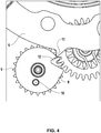
- FIG. 1 A preferred embodiment of the invention is shown on the Figures 1 to 11 .
- the instantaneous jump mechanism comprises a winding wheel 1 and a spiral spring 2.
- the central or central end 3 of the spiral spring 2 is integral with the winding wheel 2 and the distal end 4 of the spiral spring 2 is integral with an outlet ring 6, the periphery or outer edge 7 is adapted to cooperate with a substantially disk-shaped latch 8.
- This latch 8 is mounted on an integral axis of a lock pinion 9 in a manner that allows it to perform a limited rotational movement relative thereto.
- This rotational movement is delimited by the displacement, inside an oblong hole 11 visible on the figure 2 , a pin 10 connecting the lock 8 to the lock pinion 9.
- the lock 8 has a notch 12 and that the output ring 6 has teeth 13 capable of being received in the notch 12.
- a driving wheel 14 which may be the mobile unit of a timepiece driven by a time train, rotates counterclockwise (as represented by the arrow at the figure 2 ) meshing with the winding wheel 1.
- the driving wheel 14 also meshes with a return pinion 15 secured to a deflection wheel 16 driving the lock pinion 9.
- the latter also rotates counterclockwise (as also represented by the arrow in FIG. figure 2 ).
- the rotation of the winding wheel 1, by driving the center 3 of the spiral 2, allows to arm it, at least when the distal end 4 of the spiral 2 is stationary.
- This situation is represented in particular on the figure 3 , where a tooth 13 of the output ring 6 abuts against the periphery 23 of the lock 8.
- the center of the spiral 2 preferably comprises a ferrule 3 which facilitates its attachment to the winding wheel 1.
- This fixing can be done by means of fixing pins 17, for example three in number, which connect the ferrule 3 to the winding wheel 1 by occupying positioning holes provided all around the axis common to the shell 3 and the winding wheel 1.
- the fixing pins 17 and the corresponding positioning holes are spaced around the axis common to the shell 3 and the winding wheel 1 regularly.
- the drive wheel 14 rotates continuously counterclockwise and drives the winding wheel 1.
- the latter by means of the pins 17, drives the center 3 of the spiral 2.
- the distal end 4 of the hairspring 2 can not rotate because it is fixed to the output ring 6 and one of the teeth 13 of the periphery 7 thereof is blocked by the latch 8.
- the center 3 of the spiral 2 rotates, which makes it possible to arm the latter.
- the driving wheel 14 also drives the lock pinion 9 via the idler gear 15 and the idler wheel 16. As already mentioned, the pin 10 connects the lock pinion 9 to the lock 8.
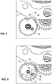
- the notch 12 formed in the lock 8 is intended to cause the release of the output mobile 6. This occurs once per turn of the lock 8.
- the lock 8 preferably has a spout 19 and the output wheel 6 a clearance 20 close to the tooth 13 allowing the passage of the spout 19.
- the spout 19 of the lock 8 prevents in particular the lock 8 to turn in direction hour and cause an untimely release of the output wheel 6. This situation could especially occur after a voluntary release, during a rebound of the lock 8 which would project it clockwise.
- the figure 8 corresponds to the figure 7 by showing, by transparency of the latch 8, the displacement of the pin 10 inside the oblong hole 11.
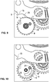
- the figure 10 which corresponds to the situation of figure 9 , shows that the pin 10 has meanwhile arrived at the end position 21 of the oblong hole 11.
- the idler gear 15 and its idler wheel 16 are preferably mounted coaxially on an axle by providing a frictional connection, which allows a precise adjustment of the moment of release of the output mobile 6.
- the shell 3 preferably comprises several positioning holes 17 for the fixing pins 18.
- the shell 3 preferably comprises several positioning holes 17 for the fixing pins 18.
- the mechanism according to the invention can be used in all kinds of applications.
- the skilled person can adapt easily by changing the size of the parts, the gear ratios, the number of return wheels, the number of teeth 13 of the output mobile 6, etc.
- the mobile output 6 can be made in one piece with the spiral spring 2, which may or may not form a single piece with a ferrule 3.
- the low resistive torque of the jump mechanism according to the invention makes it possible to drive a device for displaying the heavy and bulky minutes without unduly altering the operation of the basic movement.
- On the mobile output can for example come to set a cage of minutes composed of two bridges and five mobiles supporting the minutes disks.
- the minute cage can be held between a turntable and a stick bridge.
Description
La présente invention concerne un mécanisme de saut instantané à faible consommation d'énergie. Plus particulièrement, la présente invention concerne un mécanisme de saut instantané comportant un mobile d'armage, un ressort spiral dont une extrémité est solidaire du mobile d'armage et l'autre d'un mobile de sortie dont la périphérie est apte à coopérer avec un moyen de blocage.The present invention relates to an instant jump mechanism with low power consumption. More particularly, the present invention relates to an instantaneous jump mechanism comprising a mobile armature, a spiral spring whose one end is secured to the armoring mobile and the other of an output mobile whose periphery is adapted to cooperate with blocking means.
On connaît d'après la demande de brevet suisse publiée sous le numéro
La demande de brevet européen publiée sous le numéro
La demande de brevet français publiée sous le numéro
Le brevet
Le but majeur de l'invention est de proposer un mécanisme de saut instantané à faible couple et donc, à faible consommation d'énergie.The major object of the invention is to provide an instant jump mechanism with low torque and therefore low energy consumption.
Ce but est atteint au moyen d'un mécanisme de saut instantané comportant un mobile d'armage, un ressort spiral dont une extrémité est solidaire du mobile d'armage et l'autre d'un mobile de sortie dont la périphérie est apte à coopérer avec un moyen de blocage, ce mécanisme ayant ceci de particulier que l'extrémité centrale du ressort spiral est fixée au mobile d'armage et son extrémité distale au mobile de sortie.This object is achieved by means of an instantaneous jump mechanism comprising an armature mobile, a spiral spring whose one end is secured to the armoring mobile and the other of an output mobile whose periphery is able to cooperate. with a locking means, this mechanism having this particular that the central end of the spiral spring is fixed to the mobile armature and its distal end to the mobile output.
Ainsi, le couple de résistance que l'ensemble d'un tel mécanisme oppose au rouage du mouvement de base d'une pièce d'horlogerie a l'avantage d'être faible et très constant. De plus, la différence de couple du spiral entre le début et la fin de l'armage est relativement petite.Thus, the resistance torque that the whole of such a mechanism opposes the wheel of the basic movement of a timepiece has the advantage of being low and very constant. In addition, the difference in torque of the hairspring between the beginning and end of the haft is relatively small.
Un tel mécanisme est en outre facile à réaliser et à régler.Such a mechanism is also easy to achieve and adjust.
Des caractéristiques avantageuses du mécanisme selon l'invention sont indiquées aux points 2 à 11 suivants :
- 2. Mécanisme de saut instantané tel que décrit précédemment, dans lequel le moyen de blocage est un verrou fixé à un pignon de verrou d'une manière qui lui permet d'effectuer un mouvement de rotation limité par rapport à ce pignon.
- 3. Mécanisme selon le
point 2, dans lequel la fixation du verrou est réalisée au moyen d'une goupille pouvant se déplacer à l'intérieur d'un trou oblong. - 4. Mécanisme selon le
point 2 ou 3, dans lequel le verrou présente une encoche et le mobile de sortie comporte au moins une dent apte à être reçue dans cette encoche. - 5. Mécanisme selon le
point 2 ou l'un despoints 3 et 4, lorsque ceux-ci se rattachent aupoint 2, dans lequel le mobile d'armage et le pignon de verrou sont reliés cinématiquement à un même mobile d'entraînement. - 6. Mécanisme selon le
point 2 ou l'un despoints 3 à 5, lorsque ceux-ci se rattachent aupoint 2, dans lequel une roue de renvoi solidaire d'un pignon de renvoi est prévue entre le mobile d'entraînement et le pignon de verrou, la liaison entre la roue de renvoi et son pignon de renvoi étant prévue pour permettre une friction. - 7. Mécanisme tel que décrit précédemment, dans lequel l'extrémité centrale du ressort spiral comprend une virole comportant plusieurs trous de positionnement aptes à recevoir des goupilles de fixation au mobile d'armage. Grâce à cette caractéristique, il est notamment possible d'ajuster l'armage du spiral
- 8. Mécanisme tel que décrit précédemment, dans lequel le moyen de blocage présente un bec et le mobile de sortie un dégagement prévu pour recevoir ce bec.
- 9. Mécanisme tel que décrit précédemment, dans lequel un frottement est prévu entre la périphérie du moyen de blocage et celle du mobile de sortie.
- 10. Pièce d'horlogerie comportant un mécanisme tel que décrit précédem ment.
- 2. Instant jump mechanism as described above, wherein the locking means is a lock attached to a lock pinion in a manner that allows it to perform a limited rotational movement relative to the pinion.
- 3. Mechanism according to
point 2, wherein the fixing of the lock is carried out by means of a pin which can move inside an oblong hole. - 4. Mechanism according to
point - 5. Mechanism according to
point 2 or one ofpoints point 2, wherein the mobile armature and the lock pinion are kinematically connected to a single driving mobile. - 6. Mechanism according to
point 2 or one ofpoints 3 to 5, when these are attached topoint 2, in which a return wheel secured to a pinion gear is provided between the driving wheel and the lock pinion, the connection between the idler wheel and its idler gear being provided to allow friction. - 7. Mechanism as described above, wherein the central end of the spiral spring comprises a ferrule having a plurality of positioning holes adapted to receive fixing pins to the mobile arming. Thanks to this characteristic, it is in particular possible to adjust the winding of the hairspring
- 8. Mechanism as described above, wherein the locking means has a spout and the mobile output a clearance provided to receive the spout.
- 9. Mechanism as described above, wherein a friction is provided between the periphery of the locking means and that of the output mobile.
- 10. Timepiece comprising a mechanism as described above.
D'autres caractéristiques et avantages de l'invention vont maintenant être décrits en détail dans l'exposé suivant qui est donné en référence aux figures annexées, lesquelles représentent schématiquement :
-
figure 1 : une vue d'ensemble de dessus d'un mode de réalisation préféré du mécanisme de saut instantané selon l'invention ; -
figure 2 : une partie du mécanisme de lafigure 1 , faisant apparaître les liaisons cinématiques entre ses pièces constituantes ; -
figure 3 : une vue d'une partie du mécanisme desfigures 1 et2 ; et -
figures 4 à 11 : des détails du mécanisme desfigures 1 à 3 , destinées à illustrer son fonctionnement.
-
figure 1 : a top view of a preferred embodiment of the instant jump mechanism according to the invention; -
figure 2 : part of the mechanism of thefigure 1 , showing the kinematic links between its component parts; -
figure 3 : a view of a part of the mechanism offigures 1 and2 ; and -
Figures 4 to 11 : details of the mechanism ofFigures 1 to 3 , intended to illustrate its operation.
Un mode de réalisation préféré de l'invention est représenté sur les
Sur la
Ce verrou 8 est monté sur un axe solidaire d'un pignon de verrou 9 d'une manière qui lui permet d'effectuer un mouvement de rotation limité par rapport à celui-ci.This
Ce mouvement de rotation est délimité par le déplacement, à l'intérieur d'un trou oblong 11 visible sur la
En revenant à la
Sur la
Un mobile d'entraînement 14, qui peut être le mobile des unités d'une pièce d'horlogerie entraîné par un rouage de temps, tourne en sens antihoraire (comme représenté par la flèche à la
Parallèlement, le mobile d'entraînement 14 engrène aussi avec un pignon de renvoi 15 solidaire d'une roue de renvoi 16 entraînant le pignon de verrou 9. Ainsi, ce dernier tourne également en sens antihoraire (comme également représenté par la flèche à la
La rotation de la roue d'armage 1, en entraînant le centre 3 du spiral 2, permet d'armer celui-ci, du moins, lorsque l'extrémité distale 4 du spiral 2 est immobile. Cette situation est représentée en particulier sur la
Comme on peut le voir sur les
Comme représenté par la flèche à la
Le mobile d'entraînement 14 entraîne aussi le pignon de verrou 9 par l'intermédiaire du pignon de renvoi 15 et de la roue de renvoi 16. Comme déjà mentionné, la goupille 10 relie le pignon de verrou 9 au verrou 8.The
L'encoche 12 pratiquée dans le verrou 8 est destinée à provoquer la libération du mobile de sortie 6. Ceci se produit une fois par tour du verrou 8.The
Le déroulement de cette libération est illustré par les
Sur la
Sur la
Comme on peut le voir sur la
Sur la
La
Les rotations de l'anneau de sortie 6 et du verrou 8 continuent, et, une fois arrivée à la situation de la
La
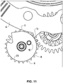
Par la suite, la rotation de l'anneau de sortie 6 se poursuit jusqu'à ce qu'une nouvelle dent 13 vienne buter contre la périphérie du verrou 8 et on arrive ainsi à la situation de la
La rotation du pignon de verrou 9 continue toujours dans le sens antihoraire, ce qui a pour conséquence que la goupille 10 revient progressivement à sa position initiale 22 dans le trou oblong 11, c'est-à-dire celle située à l'extrémité opposée, par rapport à la position finale 21, de l'arc de cercle formé par le trou oblong 11 (cf.
Ensuite, le pignon 9 se remet à entraîner en rotation le verrou 8 par l'intermédiaire de la goupille 10 en butée contre l'extrémité 22 du trou oblong 11, jusqu'à ce que l'on arrive à la situation de la
Le pignon de renvoi 15 et sa roue de renvoi 16 sont de préférence montés coaxialement sur un axe en prévoyant une liaison par friction, ce qui permet un ajustement précis du moment de la libération du mobile de sortie 6.The
La virole 3 comprend préférentiellement plusieurs trous de positionnement 17 pour les goupilles de fixation 18. Ainsi, il est possible de plus ou moins préarmer le spiral 2, en changeant de trous de positionnement 17 recevant les goupilles de fixation 18, ce qui se traduit par un déplacement angulaire de la virole 3 par rapport à la roue d'armage 1 et donc à une modification de l'intensité de l'armage du spiral 2.The
Le mécanisme selon l'invention peut être utilisé dans toutes sortes d'applications. L'homme du métier peut l'adapter aisément en modifiant la taille des pièces, les rapports d'engrenage, le nombre de roues de renvoi, le nombre de dents 13 du mobile de sortie 6, etc.The mechanism according to the invention can be used in all kinds of applications. The skilled person can adapt easily by changing the size of the parts, the gear ratios, the number of return wheels, the number of
Le mobile de sortie 6 peut être réalisé d'un seul tenant avec le ressort spiral 2, lequel peut ou non former une seule pièce avec une virole 3.The
La libération du mobile de sortie se produit instantanément, c'est pour cette raison qu'on emploie l'expression « saut instantané ». Ce saut peut être mis en oeuvre dans des mécanismes variés, notamment d'affichage des dizaines de minutes et des heures. Ainsi, si le mobile d'entraînement est le mobile des unités d'une pièce d'horlogerie, sa vitesse est de 1/5ème de tour par minute, la vitesse du verrou 8 est de 1 tour par minute et le cycle décrit ci-dessus se produit toutes les minutes.The release of the mobile output occurs instantly, it is for this reason that the term "instant jump" is used. This jump can be implemented in various mechanisms, including display tens of minutes and hours. Thus, if the driving wheel is the mobile units of a timepiece, its speed is 1/5 th of a minute, the speed of the
Le faible couple résistif du mécanisme de saut selon l'invention permet d'entraîner un dispositif d'affichage des minutes lourd et volumineux sans trop altérer le fonctionnement du mouvement de base. Sur le mobile de sortie peut par exemple venir se fixer une cage des minutes composée de deux ponts et de cinq mobiles supportant les disques des minutes. La cage des minutes peut être maintenue entre une platine et un pont baguette.The low resistive torque of the jump mechanism according to the invention makes it possible to drive a device for displaying the heavy and bulky minutes without unduly altering the operation of the basic movement. On the mobile output can for example come to set a cage of minutes composed of two bridges and five mobiles supporting the minutes disks. The minute cage can be held between a turntable and a stick bridge.
Claims (10)
- Instant jumping mechanism comprising a winding mobile (1), a spiral spring (2), one end (3) of which is integral with the winding mobile (1) and the other (4) with an exit mobile (6), the periphery (7) of which is able to cooperate with a locking means (8), the central end (3) of the spiral spring (2) being fixed to the winding mobile (1) and its distal end (4) to the exit mobile (6), characterized in that the exit mobile (6) has substantially the shape of a ring inside which the spiral spring (2) is disposed.
- Mechanism according to claim 1, wherein the locking means is a locking piece (8) fixed to a locking pinion (9) in a manner which allows it to carry out a movement of rotation limited with respect to this pinion (9).
- Mechanism according to claim 2, wherein the fixation of the locking piece (8) is achieved by means of a pin (10) able to be displaced inside a slot (11).
- Mechanism according to claim 2 or 3, wherein the locking piece (8) has a notch (12), and the exit mobile (6) comprises at least one tooth (13) able to be received in this notch (12).
- Mechanism according to claim 2 or one of the claims 3 and 4, when they are linked to claim 2, wherein the winding mobile (1) and the locking pinion (9) are connected kinematically to a same drive mobile (14).
- Mechanism according to claim 2 or one of the claims 3 to 5, when they are linked to claim 2, wherein an intermediate wheel (16), integral with an intermediate pinion (15), is provided between the drive mobile (14) and the locking pinion (9), the connection between the intermediate wheel (16) and its intermediate pinion (15) being provided to permit friction.
- Mechanism according to one of the claims 1 to 6, wherein the central end (3) of the spiral spring (2) comprises a collet comprising a plurality of positioning holes (17) able to receive pins (17) of fixation to the winding mobile (1).
- Mechanism according to one of the claims 1 to 7, wherein the locking means (8) has a beak (19) and the exit mobile (6) a recess (20) provided to receive this beak (19).
- Mechanism according to one of the claims 1 to 8, wherein friction is foreseen between the periphery (23) of the locking means (8) and that (7) of the exit mobile (6).
- Timepiece comprising a mechanism according to one of the claims 1 to 9.
Priority Applications (2)
| Application Number | Priority Date | Filing Date | Title |
|---|---|---|---|
| EP15170344.4A EP2952973B1 (en) | 2013-04-30 | 2013-04-30 | Instant jumping mechanism for timepieces |
| ES15170344.4T ES2661863T3 (en) | 2013-04-30 | 2013-04-30 | Instant jump mechanism for watch piece |
Applications Claiming Priority (2)
| Application Number | Priority Date | Filing Date | Title |
|---|---|---|---|
| EP15170344.4A EP2952973B1 (en) | 2013-04-30 | 2013-04-30 | Instant jumping mechanism for timepieces |
| EP20130166004 EP2799938A1 (en) | 2013-04-30 | 2013-04-30 | Instant jumping mechanism |
Related Parent Applications (1)
| Application Number | Title | Priority Date | Filing Date |
|---|---|---|---|
| EP20130166004 Division EP2799938A1 (en) | 2013-04-30 | 2013-04-30 | Instant jumping mechanism |
Publications (3)
| Publication Number | Publication Date |
|---|---|
| EP2952973A2 EP2952973A2 (en) | 2015-12-09 |
| EP2952973A3 EP2952973A3 (en) | 2016-06-08 |
| EP2952973B1 true EP2952973B1 (en) | 2017-12-06 |
Family
ID=48236702
Family Applications (2)
| Application Number | Title | Priority Date | Filing Date |
|---|---|---|---|
| EP20130166004 Withdrawn EP2799938A1 (en) | 2013-04-30 | 2013-04-30 | Instant jumping mechanism |
| EP15170344.4A Active EP2952973B1 (en) | 2013-04-30 | 2013-04-30 | Instant jumping mechanism for timepieces |
Family Applications Before (1)
| Application Number | Title | Priority Date | Filing Date |
|---|---|---|---|
| EP20130166004 Withdrawn EP2799938A1 (en) | 2013-04-30 | 2013-04-30 | Instant jumping mechanism |
Country Status (2)
| Country | Link |
|---|---|
| EP (2) | EP2799938A1 (en) |
| ES (1) | ES2661863T3 (en) |
Families Citing this family (6)
| Publication number | Priority date | Publication date | Assignee | Title |
|---|---|---|---|---|
| JP7473300B2 (en) | 2018-04-30 | 2024-04-23 | ロレックス・ソシエテ・アノニム | Clock Display System |
| EP3598242A1 (en) * | 2018-07-19 | 2020-01-22 | Patek Philippe SA Genève | Cam timepiece mechanism |
| EP3598243B1 (en) | 2018-07-19 | 2022-10-19 | Patek Philippe SA Genève | Timepiece mechanism with jumping member |
| EP3598241B1 (en) * | 2018-07-19 | 2022-11-09 | Patek Philippe SA Genève | Clock mechanism having a constant-force device |
| CH715723B1 (en) * | 2019-01-10 | 2022-08-15 | Richemont Int Sa | Instant jump mechanism of a display mobile. |
| CH717359B1 (en) * | 2020-04-29 | 2022-11-30 | Van Cleef & Arpels SA | Device for triggering a watch mechanism. |
Family Cites Families (6)
| Publication number | Priority date | Publication date | Assignee | Title |
|---|---|---|---|---|
| CH339129A (en) * | 1957-12-16 | 1959-06-15 | Longines Montres Comp D | Timepiece with instantaneous dates |
| CH525507A (en) * | 1969-11-03 | 1971-08-13 | Tissot Horlogerie | Drive mechanism for a date indicator in a timepiece |
| CH524847A (en) * | 1970-07-10 | 1972-02-29 | Omega Brandt & Freres Sa Louis | Calendar watch |
| EP2068210A3 (en) | 2007-12-04 | 2011-04-20 | Chronode SA | Trigger device |
| FR2947066B1 (en) | 2009-06-19 | 2011-06-17 | Francois Quentin | WATCH WITH TIME DISPLAY IN DIGITAL FORM AND JUMP CONTROL |
| CH704915B1 (en) | 2011-05-11 | 2016-02-29 | Manuf La Joux Perret Sa | A display device jumping improved. |
-
2013
- 2013-04-30 ES ES15170344.4T patent/ES2661863T3/en active Active
- 2013-04-30 EP EP20130166004 patent/EP2799938A1/en not_active Withdrawn
- 2013-04-30 EP EP15170344.4A patent/EP2952973B1/en active Active
Non-Patent Citations (1)
| Title |
|---|
| None * |
Also Published As
| Publication number | Publication date |
|---|---|
| EP2799938A1 (en) | 2014-11-05 |
| EP2952973A2 (en) | 2015-12-09 |
| ES2661863T3 (en) | 2018-04-04 |
| EP2952973A3 (en) | 2016-06-08 |
Similar Documents
| Publication | Publication Date | Title |
|---|---|---|
| EP2952973B1 (en) | Instant jumping mechanism for timepieces | |
| EP2583143B1 (en) | Mechanism for advancing a tourbillon cage or a karrusel cage by periodic jumps | |
| EP2487546B1 (en) | High-performance bi-axial escapement, or HPBE | |
| EP2397921B1 (en) | Mechanism for a jumping tourbillon cage | |
| EP3021175B1 (en) | Split-seconds device with epicycloidal train for a timepiece | |
| EP1772783A1 (en) | Watch movement with constant-force device | |
| EP1536298A1 (en) | Calendar mechanism having entrainment and correction means for two indicators | |
| CH709328B1 (en) | Escapement, timepiece movement and timepiece. | |
| WO2011160970A1 (en) | Clockwork movement exhibiting chronograph and countdown functions | |
| EP3584643B1 (en) | Instantaneous command device for date display of timepieces | |
| CH710108A2 (en) | Mechanism constant force, motion and timepiece. | |
| EP3382468A1 (en) | Movement with extension of running reserve | |
| CH707181A2 (en) | Clockwork device for use in clockwork movement of e.g. wristwatch, has control unit kinematically connected to jumping wheel and arranged to start action in minute jumping display mechanism at instants corresponding to jumps | |
| WO2013104803A1 (en) | Clockwork movement mechanism for controlling a barrel | |
| CH703331B1 (en) | feed mechanism by periodically skipping a tourbillon cage or carousel cage. | |
| EP2990880B1 (en) | Clockwork | |
| CH710450A1 (en) | Timepiece fitted with an orbital view. | |
| CH713705A2 (en) | Mechanism with constant force, movement of timepiece and timepiece. | |
| FR2921164A1 (en) | Device i.e. sequential display module, for visualizing e.g. watch complication, has mechanical module and masking disk integrated in casing including visualizable parts and units associated to visualizable parts | |
| EP2990879B1 (en) | Clockwork | |
| WO2023105270A1 (en) | Chronograph watch movements and use thereof in timepieces | |
| EP2990881B1 (en) | Clockwork | |
| CH703330B1 (en) | advance mechanism by periodically skipping a carousel cage. | |
| WO2014033510A1 (en) | Display mechanism, for timepiece | |
| CH714615B1 (en) | Winding force transmission mechanism, movement and mechanical timepiece. |
Legal Events
| Date | Code | Title | Description |
|---|---|---|---|
| PUAI | Public reference made under article 153(3) epc to a published international application that has entered the european phase |
Free format text: ORIGINAL CODE: 0009012 |
|
| AC | Divisional application: reference to earlier application |
Ref document number: 2799938 Country of ref document: EP Kind code of ref document: P |
|
| AK | Designated contracting states |
Kind code of ref document: A2 Designated state(s): AL AT BE BG CH CY CZ DE DK EE ES FI FR GB GR HR HU IE IS IT LI LT LU LV MC MK MT NL NO PL PT RO RS SE SI SK SM TR |
|
| AX | Request for extension of the european patent |
Extension state: BA ME |
|
| PUAL | Search report despatched |
Free format text: ORIGINAL CODE: 0009013 |
|
| AK | Designated contracting states |
Kind code of ref document: A3 Designated state(s): AL AT BE BG CH CY CZ DE DK EE ES FI FR GB GR HR HU IE IS IT LI LT LU LV MC MK MT NL NO PL PT RO RS SE SI SK SM TR |
|
| AX | Request for extension of the european patent |
Extension state: BA ME |
|
| RIC1 | Information provided on ipc code assigned before grant |
Ipc: G04B 19/02 20060101AFI20160502BHEP Ipc: G04B 19/08 20060101ALI20160502BHEP |
|
| RBV | Designated contracting states (corrected) |
Designated state(s): AL AT BE BG CH CY CZ DE DK EE ES FI FR GB GR HR HU IE IS IT LI LT LU LV MC MK MT NL NO PL PT RO RS SE SI SK SM TR |
|
| 17P | Request for examination filed |
Effective date: 20160623 |
|
| GRAP | Despatch of communication of intention to grant a patent |
Free format text: ORIGINAL CODE: EPIDOSNIGR1 |
|
| INTG | Intention to grant announced |
Effective date: 20170727 |
|
| GRAS | Grant fee paid |
Free format text: ORIGINAL CODE: EPIDOSNIGR3 |
|
| GRAA | (expected) grant |
Free format text: ORIGINAL CODE: 0009210 |
|
| AC | Divisional application: reference to earlier application |
Ref document number: 2799938 Country of ref document: EP Kind code of ref document: P |
|
| AK | Designated contracting states |
Kind code of ref document: B1 Designated state(s): AL AT BE BG CH CY CZ DE DK EE ES FI FR GB GR HR HU IE IS IT LI LT LU LV MC MK MT NL NO PL PT RO RS SE SI SK SM TR |
|
| REG | Reference to a national code |
Ref country code: GB Ref legal event code: FG4D Free format text: NOT ENGLISH |
|
| REG | Reference to a national code |
Ref country code: AT Ref legal event code: REF Ref document number: 952912 Country of ref document: AT Kind code of ref document: T Effective date: 20171215 Ref country code: CH Ref legal event code: EP |
|
| REG | Reference to a national code |
Ref country code: IE Ref legal event code: FG4D Free format text: LANGUAGE OF EP DOCUMENT: FRENCH |
|
| REG | Reference to a national code |
Ref country code: DE Ref legal event code: R096 Ref document number: 602013030651 Country of ref document: DE |
|
| REG | Reference to a national code |
Ref country code: CH Ref legal event code: NV Representative=s name: BOVARD AG PATENT- UND MARKENANWAELTE, CH |
|
| REG | Reference to a national code |
Ref country code: ES Ref legal event code: FG2A Ref document number: 2661863 Country of ref document: ES Kind code of ref document: T3 Effective date: 20180404 |
|
| REG | Reference to a national code |
Ref country code: NL Ref legal event code: MP Effective date: 20171206 |
|
| REG | Reference to a national code |
Ref country code: FR Ref legal event code: PLFP Year of fee payment: 6 |
|
| REG | Reference to a national code |
Ref country code: LT Ref legal event code: MG4D |
|
| PG25 | Lapsed in a contracting state [announced via postgrant information from national office to epo] |
Ref country code: SE Free format text: LAPSE BECAUSE OF FAILURE TO SUBMIT A TRANSLATION OF THE DESCRIPTION OR TO PAY THE FEE WITHIN THE PRESCRIBED TIME-LIMIT Effective date: 20171206 Ref country code: FI Free format text: LAPSE BECAUSE OF FAILURE TO SUBMIT A TRANSLATION OF THE DESCRIPTION OR TO PAY THE FEE WITHIN THE PRESCRIBED TIME-LIMIT Effective date: 20171206 Ref country code: LT Free format text: LAPSE BECAUSE OF FAILURE TO SUBMIT A TRANSLATION OF THE DESCRIPTION OR TO PAY THE FEE WITHIN THE PRESCRIBED TIME-LIMIT Effective date: 20171206 Ref country code: NO Free format text: LAPSE BECAUSE OF FAILURE TO SUBMIT A TRANSLATION OF THE DESCRIPTION OR TO PAY THE FEE WITHIN THE PRESCRIBED TIME-LIMIT Effective date: 20180306 |
|
| REG | Reference to a national code |
Ref country code: AT Ref legal event code: MK05 Ref document number: 952912 Country of ref document: AT Kind code of ref document: T Effective date: 20171206 |
|
| PG25 | Lapsed in a contracting state [announced via postgrant information from national office to epo] |
Ref country code: GR Free format text: LAPSE BECAUSE OF FAILURE TO SUBMIT A TRANSLATION OF THE DESCRIPTION OR TO PAY THE FEE WITHIN THE PRESCRIBED TIME-LIMIT Effective date: 20180307 Ref country code: LV Free format text: LAPSE BECAUSE OF FAILURE TO SUBMIT A TRANSLATION OF THE DESCRIPTION OR TO PAY THE FEE WITHIN THE PRESCRIBED TIME-LIMIT Effective date: 20171206 Ref country code: RS Free format text: LAPSE BECAUSE OF FAILURE TO SUBMIT A TRANSLATION OF THE DESCRIPTION OR TO PAY THE FEE WITHIN THE PRESCRIBED TIME-LIMIT Effective date: 20171206 Ref country code: BG Free format text: LAPSE BECAUSE OF FAILURE TO SUBMIT A TRANSLATION OF THE DESCRIPTION OR TO PAY THE FEE WITHIN THE PRESCRIBED TIME-LIMIT Effective date: 20180306 Ref country code: HR Free format text: LAPSE BECAUSE OF FAILURE TO SUBMIT A TRANSLATION OF THE DESCRIPTION OR TO PAY THE FEE WITHIN THE PRESCRIBED TIME-LIMIT Effective date: 20171206 |
|
| PG25 | Lapsed in a contracting state [announced via postgrant information from national office to epo] |
Ref country code: NL Free format text: LAPSE BECAUSE OF FAILURE TO SUBMIT A TRANSLATION OF THE DESCRIPTION OR TO PAY THE FEE WITHIN THE PRESCRIBED TIME-LIMIT Effective date: 20171206 |
|
| PG25 | Lapsed in a contracting state [announced via postgrant information from national office to epo] |
Ref country code: EE Free format text: LAPSE BECAUSE OF FAILURE TO SUBMIT A TRANSLATION OF THE DESCRIPTION OR TO PAY THE FEE WITHIN THE PRESCRIBED TIME-LIMIT Effective date: 20171206 Ref country code: SK Free format text: LAPSE BECAUSE OF FAILURE TO SUBMIT A TRANSLATION OF THE DESCRIPTION OR TO PAY THE FEE WITHIN THE PRESCRIBED TIME-LIMIT Effective date: 20171206 Ref country code: CZ Free format text: LAPSE BECAUSE OF FAILURE TO SUBMIT A TRANSLATION OF THE DESCRIPTION OR TO PAY THE FEE WITHIN THE PRESCRIBED TIME-LIMIT Effective date: 20171206 |
|
| PGFP | Annual fee paid to national office [announced via postgrant information from national office to epo] |
Ref country code: DE Payment date: 20180420 Year of fee payment: 6 Ref country code: ES Payment date: 20180525 Year of fee payment: 6 |
|
| PG25 | Lapsed in a contracting state [announced via postgrant information from national office to epo] |
Ref country code: SM Free format text: LAPSE BECAUSE OF FAILURE TO SUBMIT A TRANSLATION OF THE DESCRIPTION OR TO PAY THE FEE WITHIN THE PRESCRIBED TIME-LIMIT Effective date: 20171206 Ref country code: AT Free format text: LAPSE BECAUSE OF FAILURE TO SUBMIT A TRANSLATION OF THE DESCRIPTION OR TO PAY THE FEE WITHIN THE PRESCRIBED TIME-LIMIT Effective date: 20171206 Ref country code: RO Free format text: LAPSE BECAUSE OF FAILURE TO SUBMIT A TRANSLATION OF THE DESCRIPTION OR TO PAY THE FEE WITHIN THE PRESCRIBED TIME-LIMIT Effective date: 20171206 Ref country code: PL Free format text: LAPSE BECAUSE OF FAILURE TO SUBMIT A TRANSLATION OF THE DESCRIPTION OR TO PAY THE FEE WITHIN THE PRESCRIBED TIME-LIMIT Effective date: 20171206 |
|
| PGFP | Annual fee paid to national office [announced via postgrant information from national office to epo] |
Ref country code: IT Payment date: 20180420 Year of fee payment: 6 Ref country code: FR Payment date: 20180420 Year of fee payment: 6 |
|
| REG | Reference to a national code |
Ref country code: DE Ref legal event code: R097 Ref document number: 602013030651 Country of ref document: DE |
|
| PG25 | Lapsed in a contracting state [announced via postgrant information from national office to epo] |
Ref country code: MT Free format text: LAPSE BECAUSE OF FAILURE TO SUBMIT A TRANSLATION OF THE DESCRIPTION OR TO PAY THE FEE WITHIN THE PRESCRIBED TIME-LIMIT Effective date: 20171206 |
|
| PLBE | No opposition filed within time limit |
Free format text: ORIGINAL CODE: 0009261 |
|
| STAA | Information on the status of an ep patent application or granted ep patent |
Free format text: STATUS: NO OPPOSITION FILED WITHIN TIME LIMIT |
|
| PGFP | Annual fee paid to national office [announced via postgrant information from national office to epo] |
Ref country code: GB Payment date: 20180418 Year of fee payment: 6 |
|
| 26N | No opposition filed |
Effective date: 20180907 |
|
| PG25 | Lapsed in a contracting state [announced via postgrant information from national office to epo] |
Ref country code: DK Free format text: LAPSE BECAUSE OF FAILURE TO SUBMIT A TRANSLATION OF THE DESCRIPTION OR TO PAY THE FEE WITHIN THE PRESCRIBED TIME-LIMIT Effective date: 20171206 Ref country code: MC Free format text: LAPSE BECAUSE OF FAILURE TO SUBMIT A TRANSLATION OF THE DESCRIPTION OR TO PAY THE FEE WITHIN THE PRESCRIBED TIME-LIMIT Effective date: 20171206 Ref country code: SI Free format text: LAPSE BECAUSE OF FAILURE TO SUBMIT A TRANSLATION OF THE DESCRIPTION OR TO PAY THE FEE WITHIN THE PRESCRIBED TIME-LIMIT Effective date: 20171206 |
|
| REG | Reference to a national code |
Ref country code: BE Ref legal event code: MM Effective date: 20180430 |
|
| REG | Reference to a national code |
Ref country code: IE Ref legal event code: MM4A |
|
| PG25 | Lapsed in a contracting state [announced via postgrant information from national office to epo] |
Ref country code: LU Free format text: LAPSE BECAUSE OF NON-PAYMENT OF DUE FEES Effective date: 20180430 |
|
| PG25 | Lapsed in a contracting state [announced via postgrant information from national office to epo] |
Ref country code: BE Free format text: LAPSE BECAUSE OF NON-PAYMENT OF DUE FEES Effective date: 20180430 |
|
| PG25 | Lapsed in a contracting state [announced via postgrant information from national office to epo] |
Ref country code: IE Free format text: LAPSE BECAUSE OF NON-PAYMENT OF DUE FEES Effective date: 20180430 |
|
| REG | Reference to a national code |
Ref country code: DE Ref legal event code: R119 Ref document number: 602013030651 Country of ref document: DE |
|
| GBPC | Gb: european patent ceased through non-payment of renewal fee |
Effective date: 20190430 |
|
| PG25 | Lapsed in a contracting state [announced via postgrant information from national office to epo] |
Ref country code: DE Free format text: LAPSE BECAUSE OF NON-PAYMENT OF DUE FEES Effective date: 20191101 Ref country code: GB Free format text: LAPSE BECAUSE OF NON-PAYMENT OF DUE FEES Effective date: 20190430 |
|
| PG25 | Lapsed in a contracting state [announced via postgrant information from national office to epo] |
Ref country code: FR Free format text: LAPSE BECAUSE OF NON-PAYMENT OF DUE FEES Effective date: 20190430 |
|
| PG25 | Lapsed in a contracting state [announced via postgrant information from national office to epo] |
Ref country code: TR Free format text: LAPSE BECAUSE OF FAILURE TO SUBMIT A TRANSLATION OF THE DESCRIPTION OR TO PAY THE FEE WITHIN THE PRESCRIBED TIME-LIMIT Effective date: 20171206 |
|
| PG25 | Lapsed in a contracting state [announced via postgrant information from national office to epo] |
Ref country code: IT Free format text: LAPSE BECAUSE OF NON-PAYMENT OF DUE FEES Effective date: 20190430 |
|
| PG25 | Lapsed in a contracting state [announced via postgrant information from national office to epo] |
Ref country code: PT Free format text: LAPSE BECAUSE OF FAILURE TO SUBMIT A TRANSLATION OF THE DESCRIPTION OR TO PAY THE FEE WITHIN THE PRESCRIBED TIME-LIMIT Effective date: 20171206 |
|
| PG25 | Lapsed in a contracting state [announced via postgrant information from national office to epo] |
Ref country code: HU Free format text: LAPSE BECAUSE OF FAILURE TO SUBMIT A TRANSLATION OF THE DESCRIPTION OR TO PAY THE FEE WITHIN THE PRESCRIBED TIME-LIMIT; INVALID AB INITIO Effective date: 20130430 Ref country code: CY Free format text: LAPSE BECAUSE OF FAILURE TO SUBMIT A TRANSLATION OF THE DESCRIPTION OR TO PAY THE FEE WITHIN THE PRESCRIBED TIME-LIMIT Effective date: 20171206 Ref country code: MK Free format text: LAPSE BECAUSE OF NON-PAYMENT OF DUE FEES Effective date: 20171206 |
|
| PG25 | Lapsed in a contracting state [announced via postgrant information from national office to epo] |
Ref country code: AL Free format text: LAPSE BECAUSE OF FAILURE TO SUBMIT A TRANSLATION OF THE DESCRIPTION OR TO PAY THE FEE WITHIN THE PRESCRIBED TIME-LIMIT Effective date: 20171206 Ref country code: IS Free format text: LAPSE BECAUSE OF FAILURE TO SUBMIT A TRANSLATION OF THE DESCRIPTION OR TO PAY THE FEE WITHIN THE PRESCRIBED TIME-LIMIT Effective date: 20180406 |
|
| REG | Reference to a national code |
Ref country code: ES Ref legal event code: FD2A Effective date: 20200901 |
|
| REG | Reference to a national code |
Ref country code: CH Ref legal event code: PFA Owner name: MANUFACTURE D'HORLOGERIE AUDEMARS PIGUET SA, CH Free format text: FORMER OWNER: AUDEMARS PIGUET (RENAUD ET PAPI) SA, CH |
|
| PG25 | Lapsed in a contracting state [announced via postgrant information from national office to epo] |
Ref country code: ES Free format text: LAPSE BECAUSE OF NON-PAYMENT OF DUE FEES Effective date: 20190501 |
|
| PGFP | Annual fee paid to national office [announced via postgrant information from national office to epo] |
Ref country code: CH Payment date: 20230502 Year of fee payment: 11 |