EP3598242A1 - Cam timepiece mechanism - Google Patents
Cam timepiece mechanism Download PDFInfo
- Publication number
- EP3598242A1 EP3598242A1 EP18184529.8A EP18184529A EP3598242A1 EP 3598242 A1 EP3598242 A1 EP 3598242A1 EP 18184529 A EP18184529 A EP 18184529A EP 3598242 A1 EP3598242 A1 EP 3598242A1
- Authority
- EP
- European Patent Office
- Prior art keywords
- clock mechanism
- cam
- return spring
- elastic arm
- cam follower
- Prior art date
- Legal status (The legal status is an assumption and is not a legal conclusion. Google has not performed a legal analysis and makes no representation as to the accuracy of the status listed.)
- Withdrawn
Links
Images


Classifications
-
- G—PHYSICS
- G04—HOROLOGY
- G04B—MECHANICALLY-DRIVEN CLOCKS OR WATCHES; MECHANICAL PARTS OF CLOCKS OR WATCHES IN GENERAL; TIME PIECES USING THE POSITION OF THE SUN, MOON OR STARS
- G04B19/00—Indicating the time by visual means
- G04B19/02—Back-gearing arrangements between gear train and hands
-
- G—PHYSICS
- G04—HOROLOGY
- G04B—MECHANICALLY-DRIVEN CLOCKS OR WATCHES; MECHANICAL PARTS OF CLOCKS OR WATCHES IN GENERAL; TIME PIECES USING THE POSITION OF THE SUN, MOON OR STARS
- G04B11/00—Click devices; Stop clicks; Clutches
-
- G—PHYSICS
- G04—HOROLOGY
- G04B—MECHANICALLY-DRIVEN CLOCKS OR WATCHES; MECHANICAL PARTS OF CLOCKS OR WATCHES IN GENERAL; TIME PIECES USING THE POSITION OF THE SUN, MOON OR STARS
- G04B19/00—Indicating the time by visual means
- G04B19/24—Clocks or watches with date or week-day indicators, i.e. calendar clocks or watches; Clockwork calendars
-
- G—PHYSICS
- G04—HOROLOGY
- G04F—TIME-INTERVAL MEASURING
- G04F7/00—Apparatus for measuring unknown time intervals by non-electric means
- G04F7/04—Apparatus for measuring unknown time intervals by non-electric means using a mechanical oscillator
- G04F7/08—Watches or clocks with stop devices, e.g. chronograph
- G04F7/0866—Special arrangements
Definitions
- the present invention relates to a cam clock mechanism.
- Mechanisms are known in watchmaking for instantaneous driving of an indicator comprising a spiral cam known as a snail cam or snail cam against which a rocker rests under the action of a return spring applied against the rocker.
- the return spring is a V-shaped, U-shaped or spiral blade.
- the rocker slides from the lower part towards the upper part of the cam, which gradually arms the return spring, then the rocker drops from said upper part to said lower part, this sudden movement, considered instantaneous, being used to actuate an indicator such as a needle associated with a scale or a disc bearing indications and cooperating with a window.
- Patent applications CH 702137 and EP 2241944 describe such mechanisms for a minute counter.
- This variation in torque increases the energy consumption and affects the regularity of the oscillations of the regulating body of the watch and therefore the accuracy of the measurement.
- the present invention aims to alleviate these problems and proposes for this purpose a timepiece mechanism according to claim 1, namely a timepiece mechanism comprising a cam intended to be driven in rotation, a cam follower and a return spring arranged to hold the follower cam resting against the cam, the return spring being arranged to work within a predetermined range of winding angles during each rotation of the cam, characterized in that the stiffness of the return spring is zero or negative in at least part of the predetermined range.
- the invention further provides a timepiece, such as a wristwatch or a pocket watch, comprising this timepiece mechanism.
- a clockwork mechanism 1 is shown according to an exemplary embodiment of the invention, mounted on a frame 1a.
- the mechanism 1 is an instantaneous minute counter mechanism of a chronograph. It includes a rocker 2 pivoted in O and having a feeler 3 cooperating with a snail cam 4 mounted on, and driven by, the chronograph axis 5.
- This chronograph axis 5 carries at its upper end the hand indicating the seconds of chronograph 6 and is integral in rotation with the chronograph wheel 7 and the chronograph seconds reset heart 8.
- the lever 2 is held in abutment against the periphery of the snail cam 4 by a lever return spring 9 acting on the axis 10 of a finger 11, this finger 11 acting itself on the lever 2.
- the cooperation between the finger 11 and the lever 2 is of the rolling type.
- the finger 11 indeed interacts with the wall of a recess 12 of the rocker 2 in the manner of an engagement, almost without friction.
- the rocker 2 and the finger 11 thus rotate in opposite directions.
- a hook 13 is pivoted at P on the free end of the lever 2 and is subjected to the action of a hook return spring 14, mounted on the lever 2, tending to apply the spout 15 of the hook 13 against the wolf teeth teeth of a minute counter wheel 16.
- the axis 17 of the minute counter wheel 16 carries a chronograph minute indicator 18, such as a hand (as shown) or a disc, displaying the chronograph minutes in cooperation with the chronograph dial.
- a heart for resetting the chronograph minutes 19 to zero is integral in rotation with the minute counter wheel 16.
- the minute counter wheel 16 is held in angular positions determined between its successive actuations by a jumper 20 on which acts a jumper return spring 21.
- the snail cam 4 has a slot 22 in its terminal part, in accordance with the teaching of the patent application EP 2241944 , but it could have a more classic shape, without this slot 22.
- the rocker 2 and its return spring 9 are armed as the probe 3 slides from the bottom part B towards the top part H of the cam 4.
- Each minute, the probe 3 and with it all the rocker 2 falls from the upper part H to the lower part B of the snail cam 4 under the action of the rocker return spring 9.
- the hook 13 advances the wheel one step of the minute counter 16 to instantly change the value indicated by the chronograph minute indicator 18.
- the hook 13 passes from the the minute counter wheel 16 in which it was located during the fall in the previous crank against the action of its return spring 14, to again advance the minute counter wheel 16 during one step the next fall of rocker 2.
- the rocker return spring 9 is specially shaped to improve the constancy of the torque or moment of force which it exerts (indirectly) on the cam 4 and thus, on the one hand, improve the regularity of the oscillations of the chronograph regulator and therefore the accuracy of the measurement and, on the other hand, reduce energy consumption.
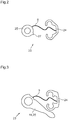
- the rocker return spring 9 is in the form of an elastic arm or blade forming part of a part 23 further comprising a base 24 and a rotary element 25, the elastic arm 9 connecting the base 24 to the element rotary 25, only the elastic arm 9 deforms during the operation of the mechanism 1.
- the base 24 is fixed, for example by means of pins 26, to the frame 1a.
- the rotary element 25, intended to rotate on itself, is eccentric relative to the base 24.
- the rotary element 25 is mounted on the axis 10 of the finger 11 and is integral in rotation with this finger 11.
- the rotary element 25 is the finger 11 itself, in other words the base 24, the elastic arm 9 and the finger 11 form the part 23.
- the part 23 is typically monobloc. It is for example made of metal, alloy, silicon, plastic, mineral glass or metallic glass. It can be produced by machining or by the LIGA technique, in particular in the case where it is made of a metal or alloy, by deep reactive ion etching known as DRIE, in particular in the case where it is made of silicon, by molding, in particular in the case where it is made of plastic or metallic glass, or by laser cutting, in particular in the case where it is made of mineral glass.
- DRIE deep reactive ion etching
- the part 23 Due to the shape of its elastic arm 9, the part 23 has a preferred direction of rotation of its rotary element 25 relative to its base 24, this direction being defined as that which allows, from a state of rest, the isolated piece 23 in which its elastic arm 9 is at rest, the greatest relative angular displacement of the rotary element 25 relative to the base 24.
- This preferred direction of rotation is the counterclockwise direction to the figure 1 and clockwise at the figure 2 .
- ⁇ be the angular position of the rotary element 25 of the isolated part 23 relative to the base 24, ⁇ being equal to zero when the isolated part 23 is at rest, that is to say when its elastic arm 9 is at rest, and increasing with the relative angular displacement of the rotary element 25 relative to the base 24 in the preferred direction of rotation of the isolated piece 23;
- the figure 4 illustrates the evolution M ( ⁇ ) of the elastic return moment exerted by the elastic arm 9 in the piece 23 isolated as a function of the angular position ⁇ of the rotary element 25 relative to the base 24.
- the isolated piece 23 having a curve M ( ⁇ ) of the type of that shown in the figure 4 differs from conventional elastic structures. Its properties are based on a sinuous shape of its elastic arm 9 which deforms so as to generate a substantially constant elastic return moment (the curve M ( ⁇ ) has a plateau between ⁇ 1 and ⁇ 2 ) over a predetermined range of angular positions of its rotary element 25 relative to its base 24. Obtaining such an elastic arm 9 requires a specific and parameterized design.
- the topological optimization discussed in the aforementioned article uses parametric polynomial curves such as the Bézier curves to determine the geometric shape of the elastic arm.
- the geometric shape of the elastic arm 9 is a Bézier curve whose control points have been optimized to take into account, in particular, the dimensions of the part 23 to be designed as well as a constraint "(M max -M min ) / ( (M max + M min ) / 2) ⁇ 0.05 ".
- the inequality "(M max -M min ) / ((M max + M min ) / 2) ⁇ 0.05" corresponds to a constancy of the elastic return moment of 5% over an angular range.
- the elastic arm or rocker return spring 9 is designed, in particular by its shape, to exert, in the part 23, a substantially constant elastic return moment (constancy of 5%) over a range of angular positions of the rotary element 25 relative to the base 24 of at least 10 °, preferably at least 15 °, more preferably at least 20 °.
- control points Q 0 , Q 1 , Q 2 , Q 3 , Q 4 , Q 5 , Q 6 were used.
- the coordinates of these control points are given in table 1 below.
- the Bézier curve has been broken down into two segments, a first segment corresponding to a curve of Bézier of order 4 based on control points Q 0 to Q 3 and a second segment corresponding to a Bézier curve of order 4 based on control points Q 3 to Q 6 .
- the graph of the figure 5 shows the external surface of the rotary element 25, the internal surface of the base 24 and the elastic arm 9 of the particular part 23 that the applicant has designed, the geometry of the arm 9 being defined by a curve passing through the assembly coordinates of points defined in table 2 above.
- This graph is made in an orthonormal coordinate system.
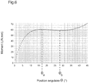
- the figure 6 represents the results of a simulation of the evolution of the elastic return moment of the particular part 23 thus produced as a function of the angular position ⁇ of its rotary element 25 relative to its base 24.
- the simulation carried out considers a part 23 produced in an amorphous alloy based on zirconium, titanium, nickel, copper and beryllium, more precisely in a metallic glass of the Vitreloy 1b type, but any suitable material can be used.
- materials such as other metallic glasses, other alloys such as Nivaflex® 45/18 (alloy based on cobalt, nickel and chromium), nickel-phosphorus or CK101 (non-alloy structural steel ), silicon, typically coated with silicon oxide, or plastic are also suitable. It is important to take into account the relationship between the elastic limit and the Young's modulus of the material to choose the material constituting the elastic arm 9.
- the stiffness of the part 23, more precisely of its elastic arm 9, is the derivative of the function M ( ⁇ ) defined above.
- the part 23 is therefore arranged so that, at each rotation of the snail cam 4 against the return action of the elastic arm or rocker return spring 9, the rotary element 25 moves in a predetermined range of angular positions relative to the base 24, this range being included in the range of positions [ ⁇ 1 , ⁇ 2 ] associated with the part 23 and comprising at least part of the range of positions [ ⁇ a , ⁇ b ] in which the stiffness of the elastic arm 9 is zero or negative.
- said predetermined range is included in the range [ ⁇ a , ⁇ b ] or constituted by the latter. More preferably, said predetermined range is included in the range] ⁇ a , ⁇ b [where the stiffness is negative at each point.
- the rotary element 25 is angularly positioned when it is mounted on the axis 10 of the finger 11 so that the rocker return spring 9 is armed with ⁇ arm degrees when the probe 3 of the flip-flop 2 is located on the lower part B of the snail cam 4, this value ⁇ arm being the lower limit of the aforementioned predetermined range.
- the rotary element 25 may include a mark 27 to be aligned for example with the finger 11.
- the part 23 is shown in its rest position, before its pre-winding.
- the length of the predetermined range is defined by the difference in radius between the upper part H and the lower part B of the cam 4, the position of the lever 2 and that of the finger 11. In the example illustrated, it is 3 °.
- the average intensity of the force applied to the snail cam 4 by the rocker return spring 9 via the finger 11 and the rocker 2 on a rotation of the snail cam 4 can be reduced compared to a traditional rocker return spring, for the same force applied to the cam 4 when the probe 3 is on the lower part B, thereby reducing the energy required to rotate the snail cam 4.
- the negative stiffness of the rocker return spring 9 also makes it possible to at least partially compensate for the variation of the lever arm of the force applied to the cam 4 by the rocker 2 on a rotation of this cam, more precisely the increase in the lever arm of the force applied to the cam 4 during the movement of the rocker 2 from the lower part B to the upper part H. A smaller variation in the torque required to rotate the cam 4 and therefore better timing can thus be obtained.
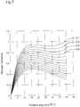
- the figure 7 shows different curves representative of a normalized moment of force M ( ⁇ ) exerted by the elastic arm 9 in the isolated part 23 for different variations in section of the elastic arm 9.
- the highest curve, designated by C1 corresponds to an arm elastic 9 of constant section and thickness (width) 30 ⁇ m.
- the curves located below the curve C1 correspond to an elastic arm 9 whose thickness increases linearly from the rotary element 25 to the base 24, the thickness at the point of junction with the base 24 being 30 ⁇ m for each curve, the thickness at the junction point with the rotary element 25 being 29 ⁇ m for the first curve C2 under the curve C1, of 28 ⁇ m for the second curve C3 under the curve C1, of 27 ⁇ m for the third curve C4 under curve C1, and so on by decrementing by 1 ⁇ m. It is noted that, for at least the first curves, the stiffness decreases (the force moment decreases more) in the range of winding angles of interest where the stiffness is negative when the variation in section is increased.
- the figure 8 shows different curves representative of a normalized moment of force M ( ⁇ ) exerted by the elastic arm 9 in the isolated part 23.
- the highest curve, designated by C1 corresponds to an elastic arm 9 of constant section and 30 ⁇ m thick.
- the curves located below the curve C1 correspond to an elastic arm 9 whose thickness increases linearly from the rotary element 25 in the middle of the elastic arm 9 and decreases linearly from the middle of the elastic arm 9 to the base 24, l ' thickness in the middle of the elastic arm 9 being 30 ⁇ m for each curve, the thickness at the junction point with the rotary element 25 and at the junction point with the base 24 being 29 ⁇ m for the first curve C2 ′ under the curve C1, 28 ⁇ m for the second curve C3 'under the curve C1, 27 ⁇ m for the third curve C4' under the curve C1, and so on by decrementing by 1 ⁇ m.
- this mode of variation of the section of the elastic arm 9 also makes it possible to adjust the negative stiffness in order for example to completely or almost completely compensate for the effect of the increase in the lever arm of the force applied to the snail cam 4 by rocker 2 during its movement from the lower part B to the upper part H.
- the elastic arm 19 In general, in cases where the elastic arm 19 has a variable section, this typically varies strictly monotonously (it increases or decreases without interruption but not necessarily linearly) over at least one continuous portion of the elastic arm representing 10% , preferably 20%, preferably 30%, preferably 40%, of the length (curvilinear) of the elastic arm.
- the variation of the section is also chosen to make the stiffness of the elastic arm 19 more negative over the range [ ⁇ a , ⁇ b ] or at least over the part of the predetermined range which overlaps with the range [ ⁇ a , ⁇ b ], relative to an elastic arm of the same shape as the arm 19 but of constant section.
- the rocker return spring or elastic arm 9 may have a shape different from that illustrated in figures 1 and 2 . It can in particular take a form as described in the article "Functional joint mechanisms with constant-torque outputs", Mechanism and Machine Theory 62 (2013) 166-181, Chia-Wen Hou et al.
- the rocker return spring 9 could comprise several elastic arms connecting the base 24 to the rotary element 25, to the like the devices described in the two articles "Design of adjustable constant-force forceps for robot-assisted surgical manipulation” and “Functional joint mechanisms with constant-torque outputs” mentioned above.
- a single elastic arm 9 is sufficient since the latter has no guiding function - the rotary element 25 is guided by the axis 10 of the finger 11 - but only fulfills an elastic return function. It will also be noted that producing the rocker return spring 9 in the form of a single elastic arm has the advantage of greater compactness.
- the choice of the number of elastic arms (s), their length and their thickness determines the intensity of the force produced.
- the present invention is not limited to a minute counter mechanism or a snail cam. It is also not limited to an instantaneous action mechanism, causing a jump movement of an indicator or other movable member. It can be applied to any watch mechanism comprising a cam which successively, one or more times per revolution, arms and disarms (partially) a rocker, a rake or other cam follower.
- the term "cam follower” means a member which cooperates with the periphery of a cam, typically for reading information, without having any function of maintaining the cam in positions determined by normal operation of the mechanism, unlike for example a jumper or a pawl cooperating with a toothed wheel to position it.
- the use of the intermediate finger 11 between the rocker return spring 9 and the rocker 2 allows, by playing on the lever arms, to reduce the size of the mechanism 1 for a given return torque applied to the rocker 2.
- this finger 11 could be removed and the rocker return spring 9 could act more directly on the rocker 2, for example the rotary element 25 could be mounted on the axis of the rocker 2.
- the return spring of lever 9 could also form a single piece with lever 2, or even be an integral part of the lever and guide in rotation relative to a base a rigid end acting as a cam follower.
Abstract
Le mécanisme horloger (1) selon l'invention comprend une came (4) destinée à être entraînée en rotation, un suiveur de came (2) et un ressort de rappel (9) agencé pour maintenir le suiveur de came (2) en appui contre la came (4), le ressort de rappel (9) étant agencé pour travailler dans une plage prédéterminée d'angles d'armage pendant chaque tour de rotation de la came (4). La raideur du ressort de rappel (9) est nulle ou négative dans au moins une partie de la plage prédéterminée.The clock mechanism (1) according to the invention comprises a cam (4) intended to be driven in rotation, a cam follower (2) and a return spring (9) arranged to hold the cam follower (2) in support. against the cam (4), the return spring (9) being arranged to work within a predetermined range of winding angles during each rotation of the cam (4). The stiffness of the return spring (9) is zero or negative in at least part of the predetermined range.
Description
La présente invention concerne un mécanisme horloger à came.The present invention relates to a cam clock mechanism.
On connaît dans l'horlogerie des mécanismes pour l'entraînement instantané d'un indicateur comprenant une came en spirale dite came escargot ou came limaçon contre laquelle s'appuie une bascule sous l'action d'un ressort de rappel appliqué contre la bascule. Le ressort de rappel est une lame en forme de V, de U ou de spirale. A chaque tour de rotation de la came, la bascule glisse de la partie basse vers la partie haute de la came, ce qui arme progressivement le ressort de rappel, puis la bascule chute de ladite partie haute à ladite partie basse, ce mouvement brusque, considéré comme instantané, étant utilisé pour actionner un indicateur tel qu'une aiguille associée à une graduation ou un disque portant des indications et coopérant avec un guichet. Les demandes de brevet
Ces mécanismes ont pour inconvénient que le couple à produire pour faire tourner la came varie en fonction du temps. En effet, le couple résistant exercé par la bascule et son ressort de rappel augmente pendant le déplacement de la bascule de la partie basse vers la partie haute de la came, ceci en raison de la force du ressort de rappel qui augmente linéairement avec son degré d'armage et aussi en raison de la forme en spirale de la came qui accroît le bras de levier de la force appliquée à la came par la bascule.These mechanisms have the disadvantage that the torque to be produced to rotate the cam varies as a function of time. Indeed, the resistant torque exerted by the rocker and its return spring increases during the movement of the rocker from the lower part to the upper part of the cam, this due to the force of the return spring which increases linearly with its degree of armament and also because of the spiral shape of the cam which increases the lever arm of the force applied to the cam by the rocker.
Cette variation de couple augmente la consommation d'énergie et affecte la régularité des oscillations de l'organe régulateur de la montre et donc la précision de la mesure.This variation in torque increases the energy consumption and affects the regularity of the oscillations of the regulating body of the watch and therefore the accuracy of the measurement.
Des problèmes similaires se posent avec d'autres types de mécanismes horlogers à came, à action instantanée ou non, par exemple les mécanismes d'affichage rétrograde comprenant une came escargot coopérant avec un râteau, le mécanisme d'affichage instantané de quantième décrit dans la demande de brevet
La présente invention vise à atténuer ces problèmes et propose à cette fin un mécanisme horloger selon la revendication 1, à savoir un mécanisme horloger comprenant une came destinée à être entraînée en rotation, un suiveur de came et un ressort de rappel agencé pour maintenir le suiveur de came en appui contre la came, le ressort de rappel étant agencé pour travailler dans une plage prédéterminée d'angles d'armage pendant chaque tour de rotation de la came, caractérisé en ce que la raideur du ressort de rappel est nulle ou négative dans au moins une partie de la plage prédéterminée.The present invention aims to alleviate these problems and proposes for this purpose a timepiece mechanism according to
Des modes de réalisation particuliers du mécanisme horloger selon l'invention sont définis dans les revendications dépendantes.Particular embodiments of the timepiece mechanism according to the invention are defined in the dependent claims.
L'invention propose en outre une pièce d'horlogerie, telle qu'une montre-bracelet ou une montre de poche, comprenant ce mécanisme horloger.The invention further provides a timepiece, such as a wristwatch or a pocket watch, comprising this timepiece mechanism.
D'autres caractéristiques et avantages de la présente invention apparaîtront à la lecture de la description détaillée suivante faite en référence aux dessins annexés dans lesquels :
- la
figure 1 est une vue plane de dessous d'un mécanisme horloger à came selon un exemple de réalisation de l'invention ; - la
figure 2 est une vue plane de dessus d'une pièce du mécanisme horloger selon l'invention comprenant un ressort de rappel ; - la
figure 3 est une vue plane de dessus d'une variante de ladite pièce ; - la
figure 4 est une représentation graphique schématique du moment de rappel élastique exercé dans la pièce illustrée à lafigure 2 ; - la
figure 5 représente les coordonnées de points définissant une forme particulière d'un bras élastique constituant le ressort de rappel ; - la
figure 6 est une représentation graphique du moment de rappel élastique exercé dans la pièce illustrée à lafigure 2 par le ressort de rappel ayant la forme telle que représentée à lafigure 5 ; - la
figure 7 est une représentation graphique d'un moment de rappel élastique normalisé exercé dans la pièce illustrée à lafigure 2 par un bras élastique ayant la forme telle que représentée à lafigure 5 selon différentes variantes du bras élastique, à savoir un tel bras à section constante (courbe C1) et un tel bras à section variable (autres courbes), la section variant selon un premier mode de variation ; - la
figure 8 est une représentation graphique d'un moment de rappel élastique normalisé exercé dans la pièce illustrée à lafigure 2 par un bras élastique ayant la forme telle que représentée à lafigure 5 selon différentes variantes du bras élastique, à savoir un tel bras à section constante (courbe C1) et un tel bras à section variable (autres courbes), la section variant selon un deuxième mode de variation.
- the
figure 1 is a plan view from below of a cam clock mechanism according to an exemplary embodiment of the invention; - the
figure 2 is a plan view from above of a part of the timepiece mechanism according to the invention comprising a return spring; - the
figure 3 is a plan view from above of a variant of said part; - the
figure 4 is a schematic graphic representation of the elastic return moment exerted in the part illustrated in thefigure 2 ; - the
figure 5 represents the coordinates of points defining a particular shape of an elastic arm constituting the return spring; - the
figure 6 is a graphic representation of the elastic return moment exerted in the part illustrated in thefigure 2 by the return spring having the shape as shown in thefigure 5 ; - the
figure 7 is a graphic representation of a normalized elastic recall moment exerted in the part illustrated in thefigure 2 by an elastic arm having the shape as shown in thefigure 5 according to different variants of the elastic arm, namely such a constant section arm (curve C1) and such a variable section arm (other curves), the section varying according to a first mode of variation; - the
figure 8 is a graphic representation of a normalized elastic recall moment exerted in the part illustrated in thefigure 2 by an elastic arm having the shape as shown in thefigure 5 according to different variants of the elastic arm, namely such a constant section arm (curve C1) and such a variable section arm (other curves), the section varying according to a second mode of variation.
A la
Un crochet 13 est pivoté en P sur l'extrémité libre de la bascule 2 et est soumis à l'action d'un ressort de rappel de crochet 14, monté sur la bascule 2, tendant à appliquer le bec 15 du crochet 13 contre la denture en dents de loup d'une roue de compteur de minutes 16. L'axe 17 de la roue de compteur de minutes 16 porte un indicateur des minutes de chronographe 18, tel qu'une aiguille (comme représenté) ou un disque, affichant les minutes de chronographe en coopération avec le cadran du chronographe. Un coeur de remise à zéro des minutes de chronographe 19 est solidaire en rotation de la roue de compteur de minutes 16. La roue de compteur de minutes 16 est maintenue dans des positions angulaires déterminées entre ses actionnements successifs par un sautoir 20 sur lequel agit un ressort de rappel de sautoir 21.A
Dans l'exemple illustré, la came escargot 4 présente une fente 22 dans sa partie terminale, conformément à l'enseignement de la demande de brevet
A chaque tour de rotation de la came escargot 4, la bascule 2 et son ressort de rappel 9 sont armés à mesure que le palpeur 3 glisse de la partie basse B vers la partie haute H de la came 4. Chaque minute, le palpeur 3 et avec lui toute la bascule 2 chute de la partie haute H à la partie basse B de la came escargot 4 sous l'action du ressort de rappel de bascule 9. Pendant cette chute, le crochet 13 fait avancer d'un pas la roue de compteur de minutes 16 pour changer de manière instantanée la valeur indiquée par l'indicateur des minutes de chronographe 18. Puis, pendant le réarmage progressif de la bascule 2 par la came escargot 4, le crochet 13 passe de l'entre-dent de la roue de compteur de minutes 16 dans lequel il se trouvait pendant la chute à l'entre-dent précédent contre l'action de son ressort de rappel 14, pour à nouveau faire avancer d'un pas la roue de compteur de minutes 16 pendant la chute suivante de la bascule 2.At each revolution of the
Selon l'invention, le ressort de rappel de bascule 9 est conformé spécialement pour améliorer la constance du couple ou moment de force qu'il exerce (indirectement) sur la came 4 et ainsi, d'une part, améliorer la régularité des oscillations de l'organe régulateur du chronographe et donc la précision de la mesure et, d'autre part, diminuer la consommation d'énergie.According to the invention, the
Comme montré aux
La pièce 23 est typiquement monobloc. Elle est par exemple en métal, alliage, silicium, plastique, verre minéral ou verre métallique. Elle peut être réalisée par usinage ou par la technique LIGA, notamment dans le cas où elle est faite d'un métal ou alliage, par gravure ionique réactive profonde dite DRIE, notamment dans le cas où elle est faite en silicium, par moulage, notamment dans le cas où elle est faite en plastique ou verre métallique, ou par découpe laser, notamment dans le cas où elle est en verre minéral.The
Pour la compréhension de l'invention, le comportement de la pièce 23 considérée isolément, c'est-à-dire libre de toute interaction avec le reste du mécanisme 1, est décrit ci-dessous. La
En raison de la forme de son bras élastique 9, la pièce 23 possède un sens de rotation privilégié de son élément rotatif 25 par rapport à sa base 24, ce sens étant défini comme celui qui permet, à partir d'un état de repos de la pièce 23 isolée dans lequel son bras élastique 9 est au repos, le plus grand déplacement angulaire relatif de l'élément rotatif 25 par rapport à la base 24. Ce sens de rotation privilégié est le sens antihoraire à la
Soit θ la position angulaire de l'élément rotatif 25 de la pièce 23 isolée par rapport à la base 24, θ étant égal à zéro lorsque la pièce 23 isolée est au repos, c'est-à-dire lorsque son bras élastique 9 est au repos, et augmentant avec le déplacement angulaire relatif de l'élément rotatif 25 par rapport à la base 24 dans le sens de rotation privilégié de la pièce 23 isolée ; la
De manière générale, lorsque l'élément rotatif 25 est dans la position angulaire dans laquelle θ = x°, on dit que la pièce 23 est armée de x°.Generally, when the
Comme cela est visible sur la courbe M(θ) de la
- pour un angle θ compris entre 0 et une première valeur θ1, le moment de rappel élastique augmente rapidement avec la position angulaire θ ;
- au-delà de cette première valeur θ1, la
pièce 23 est dans une phase sensiblement stable. En effet, entre cette première valeur θ1 et une seconde valeur θ2, le moment de rappel élastique est sensiblement constant par rapport à la position angulaire θ.
On entend par moment « sensiblement constant » un moment ne variant pas de plus de 10%, depréférence 5%, de préférence encore 3%, étant entendu que ce pourcentage peut être diminué davantage. Plus précisément, soient respectivement Mmin et Mmax les valeurs des moments minimum et maximum exercés dans la pièce 23 isolée sur une plage [θ1, θ2] donnée de positions angulaires de l'élément rotatif 25 par rapport à labase 24, le moment exercé dans cette pièce 23 isolée est sensiblement constant dès lors que l'inéquation « (Mmax-Mmin)/((Mmax+Mmin)/2) ≤ 0,1 » est vérifiée, plus précisément, dès lors que l'inéquation « (Mmax-Mmin)/((Mmax+Mmin)/2) ≤ y% », avec y=10, de préférence y=5, de préférence encore y=3, est vérifiée.
Dans cette phase sensiblement stable, le moment de rappel élastique exercé par le bras élastique 9 dans la pièce 23 isolée atteint toutefois localement un maximum pour une position angulaire θa, puis est décroissant dans l'intervalle de positions angulaires compris entre les valeurs θa et θb, où θa et θb sont compris entre θ1 et θ2 ; - au-delà de la valeur θ2, le moment de rappel élastique augmente à nouveau jusqu'à atteindre une valeur limite Mlimite, pour un déplacement angulaire θ=θ3. Cette valeur Mlimite dépend des propriétés du matériau dans lequel la pièce 23 est réalisée et correspond à la contrainte maximale que peut subir cette pièce.
- for an angle θ between 0 and a first value θ 1 , the elastic return moment increases rapidly with the angular position θ;
- beyond this first value θ 1 , the
part 23 is in a substantially stable phase. Indeed, between this first value θ 1 and a second value θ 2 , the elastic return moment is substantially constant with respect to the angular position θ.
By "substantially constant" moment is meant a moment not varying by more than 10%, preferably 5%, more preferably 3%, it being understood that this percentage can be further reduced. More precisely, let M min and M max respectively be the values of the minimum and maximum moments exerted in theisolated part 23 over a given range [θ 1 , θ 2 ] of angular positions of therotary element 25 relative to thebase 24, the moment exerted in thisisolated part 23 is substantially constant as soon as the inequality "(M max -M min ) / ((M max + M min ) / 2) ≤ 0.1" is verified, more precisely, from then on that the inequality "(M max -M min ) / ((M max + M min ) / 2) ≤ y%", with y = 10, preferably y = 5, more preferably y = 3, is verified.
In this substantially stable phase, the elastic return moment exerted by theelastic arm 9 in theisolated piece 23, however, locally reaches a maximum for an angular position θ a , then decreases in the range of angular positions between the values θ a and θ b , where θ a and θ b are between θ 1 and θ 2 ; - beyond the value θ 2 , the elastic return moment increases again until reaching a limit value M limit , for an angular displacement θ = θ 3 . This limit value M depends on the properties of the material from which the
part 23 is made and corresponds to the maximum stress that this part can undergo.
La pièce 23 isolée présentant une courbe M(θ) du type de celle représentée à la
L'optimisation topologique dont il est question dans l'article précité utilise des courbes polynomiales paramétriques telles que les courbes de Bézier pour déterminer la forme géométrique du bras élastique.The topological optimization discussed in the aforementioned article uses parametric polynomial curves such as the Bézier curves to determine the geometric shape of the elastic arm.
Les courbes de Bézier se définissent, conjointement à une série de m=(n+1) points de contrôle (Q0, Q1, ... Qn), par un ensemble de points dont les coordonnées sont données par des sommes de polynômes de Bernstein pondérées par les coordonnées desdits points de contrôle.Bézier curves are defined, together with a series of m = (n + 1) control points (Q 0 , Q 1 , ... Q n ), by a set of points whose coordinates are given by sums of Bernstein polynomials weighted by the coordinates of said control points.
La forme géométrique du bras élastique 9 est une courbe de Bézier dont les points de contrôle ont été optimisés pour prendre en compte, notamment, les dimensions de la pièce 23 à concevoir ainsi qu'une contrainte « (Mmax-Mmin)/((Mmax+Mmin)/2) ≤ 0,05 ». L'inéquation « (Mmax-Mmin)/((Mmax+Mmin)/2) ≤ 0,05 » correspond à une constance du moment de rappel élastique de 5% sur une plage angulaire.The geometric shape of the
D'une manière générale, le bras élastique ou ressort de rappel de bascule 9 est conçu, notamment de par sa forme, pour exercer, dans la pièce 23, un moment de rappel élastique sensiblement constant (constance de 5%) sur une plage de positions angulaires de l'élément rotatif 25 par rapport à la base 24 d'au moins 10°, de préférence d'au moins 15°, de préférence encore d'au moins 20°.In general, the elastic arm or
Plus précisément, la forme géométrique du bras élastique 9 est définie par l'ensemble des points ![]()
où les ![]()
![]()
et où les Qi sont les points de contrôle Q0 à Qn. Elle correspond à la représentation graphique dans un repère orthonormé de l'ensemble des points définis par les couples de coordonnées (x ; y) définis respectivement par les fonctions x(t) et y(t), t ∈ [0, 1], ci-dessous : 

![]()
where the ![]()
![]()
and where the Q i are the control points Q 0 to Q n . It corresponds to the graphic representation in an orthonormal coordinate system of all the points defined by the pairs of coordinates (x; y) defined respectively by the functions x (t) and y (t), t ∈ [0, 1], below :
Les formules indiquées ci-dessus donnent les coordonnées d'une courbe de Bézier d'ordre m, c'est-à-dire une courbe de Bézier basée sur m points de contrôle. Pour des raisons pratiques, une telle courbe de Bézier peut être décomposée en une succession de courbes de Bézier d'ordre inférieur à m, auquel cas la forme géométrique du bras élastique est une succession de courbes de Bézier.The formulas indicated above give the coordinates of a Bézier curve of order m, that is to say a Bézier curve based on m control points. For practical reasons, such a Bézier curve can be broken down into a succession of Bézier curves of order less than m, in which case the geometric shape of the elastic arm is a succession of Bézier curves.
En utilisant ce principe, la demanderesse a conçu une pièce 23 particulière ayant les dimensions suivantes :
- Distance entre le centre de rotation de l'élément rotatif 25 et le point de jonction du bras élastique 9 à l'élément rotatif 25 : 0,5 mm ;
- Distance entre le centre de rotation de l'élément rotatif 25 et le point de jonction du bras élastique 9 à la base 24 : 2,5 mm ;
- Distance entre les deux extrémités du bras élastique 9 : 2 mm
- Longueur curviligne du bras élastique 9 : 2,4 mm ;
- Epaisseur (largeur) du bras élastique 9 : 25,6 µm ;
- Hauteur de la pièce 23 : 0,3 mm.
- Distance between the center of rotation of the
rotary element 25 and the junction point of theelastic arm 9 with the rotary element 25: 0.5 mm; - Distance between the center of rotation of the
rotary member 25 and the junction point of theelastic arm 9 at the base 24: 2.5 mm; - Distance between the two ends of the elastic arm 9: 2 mm
- Curvilinear length of elastic arm 9: 2.4 mm;
- Thickness (width) of the elastic arm 9: 25.6 μm;
- Height of the workpiece 23: 0.3 mm.
Dans le cadre de cette conception, sept points de contrôle Q0, Q1, Q2, Q3, Q4, Q5, Q6 ont été utilisés. Les coordonnées de ces points de contrôle sont indiquées dans le tableau 1 ci-dessous.
Avec ces sept points de contrôle il aurait été possible de réaliser une courbe de Bézier d'ordre sept. Cependant, selon le principe indiqué ci-dessus, la courbe de Bézier a été décomposée en deux segments, un premier segment correspondant à une courbe de Bézier d'ordre 4 basée sur les points de contrôle Q0 à Q3 et un second segment correspondant à une courbe de Bézier d'ordre 4 basée sur les points de contrôle Q3 à Q6.With these seven control points it would have been possible to produce a Bézier curve of order seven. However, according to the principle indicated above, the Bézier curve has been broken down into two segments, a first segment corresponding to a curve of Bézier of
En utilisant les coordonnées des points de contrôle Q0 à Q6 ci-dessus dans les fonctions x(t) et y(t) précitées, la demanderesse a obtenu les coordonnées des points définissant la forme géométrique du bras élastique 9. Un certain nombre de ces couples de coordonnées sont donnés dans le tableau 2 ci-après.
Le graphique de la
La
La simulation effectuée considère une pièce 23 réalisée dans un alliage amorphe à base de zirconium, titane, nickel, cuivre et béryllium, plus précisément dans un verre métallique de type Vitreloy 1b, mais tout matériau approprié peut être utilisé. Par exemple des matériaux tels que d'autres verres métalliques, d'autres alliages tels que le Nivaflex® 45/18 (alliage à base de cobalt, nickel et chrome), le nickel-phosphore ou le CK101 (acier de construction non-allié), le silicium, typiquement revêtu d'oxyde de silicium, ou le plastique conviennent également. Il est important de tenir compte du rapport entre la limite élastique et le module de Young du matériau pour choisir le matériau constituant le bras élastique 9.The simulation carried out considers a
Il ressort de l'analyse des résultats présentés à la
La raideur de la pièce 23, plus précisément de son bras élastique 9, est la dérivée de la fonction M(θ) définie précédemment.The stiffness of the
Sur la plage de positions angulaires [θa, θb] la raideur est nulle aux positions angulaires θa et θb et négative entre ces positions θa et θb. Dans la présente invention, on se place dans cette plage [θa, θb] ou au moins en partie dans cette plage.On the range of angular positions [θ a , θ b ] the stiffness is zero at the angular positions θ a and θ b and negative between these positions θ a and θ b . In the present invention, one places oneself in this range [θ a , θ b ] or at least partially in this range.
Au sein du mécanisme 1, la pièce 23 est donc agencée pour que, à chaque tour de rotation de la came escargot 4 contre l'action de rappel du bras élastique ou ressort de rappel de bascule 9, l'élément rotatif 25 se déplace dans une plage prédéterminée de positions angulaires par rapport à la base 24, cette plage étant incluse dans la plage de positions [θ1, θ2] associée à la pièce 23 et comprenant au moins une partie de la plage de positions [θa, θb] dans laquelle la raideur du bras élastique 9 est nulle ou négative. De préférence, ladite plage prédéterminée est incluse dans la plage [θa, θb] ou constituée par cette dernière. De préférence encore, ladite plage prédéterminée est incluse dans la plage ]θa, θb[ où la raideur est négative en chaque point.Within the
Pour obtenir un tel agencement, l'élément rotatif 25 est positionné angulairement lors de son montage sur l'axe 10 du doigt 11 de manière à ce que le ressort de rappel de bascule 9 soit armé de θarm degrés lorsque le palpeur 3 de la bascule 2 se trouve sur la partie basse B de la came escargot 4, cette valeur θarm étant la borne inférieure de la plage prédéterminée susmentionnée. Afin de faciliter cette opération de positionnement, l'élément rotatif 25 peut comporter un repère 27 à aligner par exemple avec le doigt 11. A la
Grâce à la raideur au moins en partie nulle ou négative du ressort de rappel de bascule 9 dans la plage prédéterminée des positions angulaires que peut prendre l'élément rotatif 25 pendant le fonctionnement du mécanisme 1, l'intensité moyenne de la force appliquée à la came escargot 4 par le ressort de rappel de bascule 9 via le doigt 11 et la bascule 2 sur un tour de rotation de la came escargot 4 peut être diminuée par rapport à un ressort de rappel de bascule traditionnel, pour une même force appliquée à la came 4 lorsque le palpeur 3 est sur la partie basse B, réduisant ainsi l'énergie requise pour faire tourner la came escargot 4. Les ressorts de rappel de bascule traditionnels, en V, en U ou en spirale, présentent en effet tous un comportement linéaire, leur raideur est positive et constante sur toute leur plage de travail.Thanks to the at least partly zero or negative stiffness of the
La raideur négative du ressort de rappel de bascule 9 permet en outre de compenser en partie au moins la variation du bras de levier de la force appliquée à la came 4 par la bascule 2 sur un tour de rotation de cette came, plus précisément l'augmentation du bras de levier de la force appliquée à la came 4 pendant le déplacement de la bascule 2 de la partie basse B à la partie haute H. Une plus faible variation du couple requis pour faire tourner la came 4 et donc une meilleure chronométrie peut ainsi être obtenue.The negative stiffness of the
Il est possible d'ajuster la valeur de raideur négative en concevant le ressort de rappel de bascule ou bras élastique 9 avec une section variable. La
D'autres modes de variation de la section du bras élastique 9 peuvent être envisagés. La
De manière générale, dans les cas où le bras élastique 19 a une section variable, celle-ci varie typiquement de manière strictement monotone (elle augmente ou diminue sans interruption mais pas nécessairement linéairement) sur au moins une portion continue du bras élastique représentant 10%, de préférence 20%, de préférence 30%, de préférence 40%, de la longueur (curviligne) du bras élastique. La variation de la section est en outre choisie pour rendre plus négative la raideur du bras élastique 19 sur la plage [θa, θb] ou au moins sur la partie de la plage prédéterminée qui se recoupe avec la plage [θa, θb], par rapport à un bras élastique de même forme que le bras 19 mais de section constante.In general, in cases where the
Dans des variantes, le ressort de rappel de bascule ou bras élastique 9 peut présenter une forme différente de celle illustrée aux
Il apparaîtra clairement à l'homme du métier qu'au lieu d'être constitué d'un seul bras élastique, le ressort de rappel de bascule 9 pourrait comprendre plusieurs bras élastiques reliant la base 24 à l'élément rotatif 25, à l'instar des dispositifs décrits dans les deux articles « Design of adjustable constant-force forceps for robot-assisted surgical manipulation » et « Functional joint mechanisms with constant-torque outputs » mentionnés ci-dessus. Dans l'exemple de réalisation illustré à la
La présente invention n'est pas limitée à un mécanisme de compteur de minutes ni à une came escargot. Elle n'est pas non plus limitée à un mécanisme à action instantané, entraînant un déplacement par sauts d'un indicateur ou autre organe mobile. Elle peut s'appliquer à tout mécanisme horloger comprenant une came qui successivement, une ou plusieurs fois par tour de rotation, arme et désarme (partiellement) une bascule, un râteau ou autre suiveur de came. Dans le contexte de la présente invention, on entend par « suiveur de came » un organe qui coopère avec la périphérie d'une came, typiquement pour lire une information, sans avoir aucune fonction de maintien de la came dans des positions déterminées en fonctionnement normal du mécanisme, à la différence par exemple d'un sautoir ou d'un cliquet coopérant avec une roue dentée pour la positionner.The present invention is not limited to a minute counter mechanism or a snail cam. It is also not limited to an instantaneous action mechanism, causing a jump movement of an indicator or other movable member. It can be applied to any watch mechanism comprising a cam which successively, one or more times per revolution, arms and disarms (partially) a rocker, a rake or other cam follower. In the context of the present invention, the term "cam follower" means a member which cooperates with the periphery of a cam, typically for reading information, without having any function of maintaining the cam in positions determined by normal operation of the mechanism, unlike for example a jumper or a pawl cooperating with a toothed wheel to position it.
L'utilisation du doigt intermédiaire 11 entre le ressort de rappel de bascule 9 et la bascule 2 permet, en jouant sur les bras de levier, de diminuer l'encombrement du mécanisme 1 pour un couple de rappel donné appliqué à la bascule 2. Cependant, ce doigt 11 pourrait être supprimé et le ressort de rappel de bascule 9 pourrait agir de manière plus directe sur la bascule 2, par exemple l'élément rotatif 25 pourrait être monté sur l'axe de la bascule 2. Le ressort de rappel de bascule 9 pourrait aussi former une seule pièce avec la bascule 2, voire faire partie intégrante de la bascule et guider en rotation par rapport à une base une extrémité rigide faisant office de suiveur de came.The use of the
Claims (19)
Priority Applications (3)
| Application Number | Priority Date | Filing Date | Title |
|---|---|---|---|
| EP18184529.8A EP3598242A1 (en) | 2018-07-19 | 2018-07-19 | Cam timepiece mechanism |
| PCT/IB2019/056140 WO2020016818A1 (en) | 2018-07-19 | 2019-07-18 | Clockwork mechanism having a cam |
| EP19766359.4A EP3824354A1 (en) | 2018-07-19 | 2019-07-18 | Clockwork mechanism having a cam |
Applications Claiming Priority (1)
| Application Number | Priority Date | Filing Date | Title |
|---|---|---|---|
| EP18184529.8A EP3598242A1 (en) | 2018-07-19 | 2018-07-19 | Cam timepiece mechanism |
Publications (1)
| Publication Number | Publication Date |
|---|---|
| EP3598242A1 true EP3598242A1 (en) | 2020-01-22 |
Family
ID=63012933
Family Applications (2)
| Application Number | Title | Priority Date | Filing Date |
|---|---|---|---|
| EP18184529.8A Withdrawn EP3598242A1 (en) | 2018-07-19 | 2018-07-19 | Cam timepiece mechanism |
| EP19766359.4A Pending EP3824354A1 (en) | 2018-07-19 | 2019-07-18 | Clockwork mechanism having a cam |
Family Applications After (1)
| Application Number | Title | Priority Date | Filing Date |
|---|---|---|---|
| EP19766359.4A Pending EP3824354A1 (en) | 2018-07-19 | 2019-07-18 | Clockwork mechanism having a cam |
Country Status (2)
| Country | Link |
|---|---|
| EP (2) | EP3598242A1 (en) |
| WO (1) | WO2020016818A1 (en) |
Cited By (1)
| Publication number | Priority date | Publication date | Assignee | Title |
|---|---|---|---|---|
| EP3955064A1 (en) | 2020-08-12 | 2022-02-16 | Patek Philippe SA Genève | Timepiece component comprising an opening designed for insertion of an axis |
Families Citing this family (2)
| Publication number | Priority date | Publication date | Assignee | Title |
|---|---|---|---|---|
| EP3907563B1 (en) | 2020-05-07 | 2022-09-14 | Patek Philippe SA Genève | Timepiece mechanism comprising a pivot member |
| EP4325301A1 (en) | 2022-08-17 | 2024-02-21 | Patek Philippe SA Genève | Timepiece mechanism comprising a rotary timepiece member and a device with a predetermined angular stiffness |
Citations (6)
| Publication number | Priority date | Publication date | Assignee | Title |
|---|---|---|---|---|
| EP1746470A1 (en) | 2005-07-20 | 2007-01-24 | Breitling AG | Timepiece with calendar mechanism |
| EP2241944A2 (en) | 2009-04-15 | 2010-10-20 | Patek Philippe SA Genève | Instantaneous counter mechanism and snail cam for such mechanism |
| CH702137B1 (en) | 2007-02-05 | 2011-05-13 | Patek Philippe Sa Geneve | Device for driving and setting an instantaneous counter and timepiece including such a device. |
| CH702804A2 (en) * | 2010-03-10 | 2011-09-15 | Patek Philippe Sa Geneve | Torque converting mechanism for use in e.g. perpetual calendar mechanism in timepiece, has lever with bearing surface that includes shape formed in manner such that length of lever arm is reduced for compensating increase in return force |
| EP2645189A1 (en) * | 2012-03-29 | 2013-10-02 | Nivarox-FAR S.A. | Flexible escapement mechanism |
| EP2799938A1 (en) * | 2013-04-30 | 2014-11-05 | Audemars Piguet (Renaud et Papi) SA | Instant jumping mechanism |
-
2018
- 2018-07-19 EP EP18184529.8A patent/EP3598242A1/en not_active Withdrawn
-
2019
- 2019-07-18 EP EP19766359.4A patent/EP3824354A1/en active Pending
- 2019-07-18 WO PCT/IB2019/056140 patent/WO2020016818A1/en active Application Filing
Patent Citations (6)
| Publication number | Priority date | Publication date | Assignee | Title |
|---|---|---|---|---|
| EP1746470A1 (en) | 2005-07-20 | 2007-01-24 | Breitling AG | Timepiece with calendar mechanism |
| CH702137B1 (en) | 2007-02-05 | 2011-05-13 | Patek Philippe Sa Geneve | Device for driving and setting an instantaneous counter and timepiece including such a device. |
| EP2241944A2 (en) | 2009-04-15 | 2010-10-20 | Patek Philippe SA Genève | Instantaneous counter mechanism and snail cam for such mechanism |
| CH702804A2 (en) * | 2010-03-10 | 2011-09-15 | Patek Philippe Sa Geneve | Torque converting mechanism for use in e.g. perpetual calendar mechanism in timepiece, has lever with bearing surface that includes shape formed in manner such that length of lever arm is reduced for compensating increase in return force |
| EP2645189A1 (en) * | 2012-03-29 | 2013-10-02 | Nivarox-FAR S.A. | Flexible escapement mechanism |
| EP2799938A1 (en) * | 2013-04-30 | 2014-11-05 | Audemars Piguet (Renaud et Papi) SA | Instant jumping mechanism |
Non-Patent Citations (2)
| Title |
|---|
| CHAO-CHIEH LAN ET AL.: "IEEE International Conférence on Robotics and Automation", 2011, SHANGHAI INTERNATIONAL CONFÉRENCE CENTER, article "Design of adjustable constant-force forceps for robot-assisted surgical manipulation" |
| CHIA-WEN HOU: "Functional joint mechanisms with constant-torque outputs", MECHANISM AND MACHINE THEORY, vol. 62, 2013, pages 166 - 181, XP028970320, DOI: doi:10.1016/j.mechmachtheory.2012.12.002 |
Cited By (1)
| Publication number | Priority date | Publication date | Assignee | Title |
|---|---|---|---|---|
| EP3955064A1 (en) | 2020-08-12 | 2022-02-16 | Patek Philippe SA Genève | Timepiece component comprising an opening designed for insertion of an axis |
Also Published As
| Publication number | Publication date |
|---|---|
| EP3824354A1 (en) | 2021-05-26 |
| WO2020016818A1 (en) | 2020-01-23 |
Similar Documents
| Publication | Publication Date | Title |
|---|---|---|
| EP2927756A1 (en) | Clock movement provided with a drive mechanism for an analogue indicator with periodic or intermittent movement | |
| EP3824354A1 (en) | Clockwork mechanism having a cam | |
| EP2010971A2 (en) | Movement for timepiece with retrograde display | |
| EP3580618B1 (en) | Timepiece driving organ | |
| EP3598243B1 (en) | Timepiece mechanism with jumping member | |
| EP3690556B1 (en) | Timepiece comprising a display with variable pitch | |
| CH713787A2 (en) | Watchmaker device with positioning member | |
| EP3707565B1 (en) | Device for guiding the rotation of a mobile component | |
| EP3619579B1 (en) | Clock device with positioning member | |
| EP3185090B1 (en) | Device for counting and displaying a fraction of a time unit | |
| EP3598241B1 (en) | Clock mechanism having a constant-force device | |
| EP3435363B1 (en) | Display system having a display module by mobile elements around flexible links, and timepiece comprising such a display system | |
| EP3907563B1 (en) | Timepiece mechanism comprising a pivot member | |
| EP3707563A1 (en) | Driving member of a timepiece | |
| EP3851919A1 (en) | Repositioning device for timepieces | |
| EP3629100B1 (en) | Symmetrical device for guiding two elements, especially for timepieces | |
| EP1475682B1 (en) | Chronograph watch with immediate display of the fractions of a second | |
| EP3761122B1 (en) | Timepiece escapement component, associated escapement mechanism and timepiece | |
| EP4325301A1 (en) | Timepiece mechanism comprising a rotary timepiece member and a device with a predetermined angular stiffness | |
| EP2017681A1 (en) | Breguet overcoil for timepiece and method of manufacturing the same | |
| CH719047A9 (en) | Discontinuous clockwork drive mechanism. | |
| EP2138912B1 (en) | Horological hairspring with concentric development | |
| CH717215A2 (en) | Guide mechanism, display mechanism, movement and timepiece. | |
| CH714318A2 (en) | Clockwork motor member delivering a substantially constant force. | |
| CH716150B1 (en) | Watchmaker's mechanism for blocking a jumping mobile and movement for a chronograph watch including it. |
Legal Events
| Date | Code | Title | Description |
|---|---|---|---|
| PUAI | Public reference made under article 153(3) epc to a published international application that has entered the european phase |
Free format text: ORIGINAL CODE: 0009012 |
|
| AK | Designated contracting states |
Kind code of ref document: A1 Designated state(s): AL AT BE BG CH CY CZ DE DK EE ES FI FR GB GR HR HU IE IS IT LI LT LU LV MC MK MT NL NO PL PT RO RS SE SI SK SM TR |
|
| AX | Request for extension of the european patent |
Extension state: BA ME |
|
| STAA | Information on the status of an ep patent application or granted ep patent |
Free format text: STATUS: THE APPLICATION IS DEEMED TO BE WITHDRAWN |
|
| 18D | Application deemed to be withdrawn |
Effective date: 20200723 |