EP2946857B1 - Support d'outil de tournage et insert d'outil de coupe - Google Patents
Support d'outil de tournage et insert d'outil de coupe Download PDFInfo
- Publication number
- EP2946857B1 EP2946857B1 EP14168809.3A EP14168809A EP2946857B1 EP 2946857 B1 EP2946857 B1 EP 2946857B1 EP 14168809 A EP14168809 A EP 14168809A EP 2946857 B1 EP2946857 B1 EP 2946857B1
- Authority
- EP
- European Patent Office
- Prior art keywords
- coolant
- cutting
- shim
- insert
- extending
- Prior art date
- Legal status (The legal status is an assumption and is not a legal conclusion. Google has not performed a legal analysis and makes no representation as to the accuracy of the status listed.)
- Active
Links
Images


Classifications
-
- B—PERFORMING OPERATIONS; TRANSPORTING
- B23—MACHINE TOOLS; METAL-WORKING NOT OTHERWISE PROVIDED FOR
- B23B—TURNING; BORING
- B23B27/00—Tools for turning or boring machines; Tools of a similar kind in general; Accessories therefor
- B23B27/10—Cutting tools with special provision for cooling
-
- B—PERFORMING OPERATIONS; TRANSPORTING
- B23—MACHINE TOOLS; METAL-WORKING NOT OTHERWISE PROVIDED FOR
- B23B—TURNING; BORING
- B23B27/00—Tools for turning or boring machines; Tools of a similar kind in general; Accessories therefor
-
- B—PERFORMING OPERATIONS; TRANSPORTING
- B23—MACHINE TOOLS; METAL-WORKING NOT OTHERWISE PROVIDED FOR
- B23B—TURNING; BORING
- B23B27/00—Tools for turning or boring machines; Tools of a similar kind in general; Accessories therefor
- B23B27/14—Cutting tools of which the bits or tips or cutting inserts are of special material
- B23B27/141—Specially shaped plate-like cutting inserts, i.e. length greater or equal to width, width greater than or equal to thickness
- B23B27/143—Specially shaped plate-like cutting inserts, i.e. length greater or equal to width, width greater than or equal to thickness characterised by having chip-breakers
-
- B—PERFORMING OPERATIONS; TRANSPORTING
- B23—MACHINE TOOLS; METAL-WORKING NOT OTHERWISE PROVIDED FOR
- B23B—TURNING; BORING
- B23B27/00—Tools for turning or boring machines; Tools of a similar kind in general; Accessories therefor
- B23B27/14—Cutting tools of which the bits or tips or cutting inserts are of special material
- B23B27/16—Cutting tools of which the bits or tips or cutting inserts are of special material with exchangeable cutting bits or cutting inserts, e.g. able to be clamped
- B23B27/1614—Cutting tools of which the bits or tips or cutting inserts are of special material with exchangeable cutting bits or cutting inserts, e.g. able to be clamped with plate-like cutting inserts of special shape clamped against the walls of the recess in the shank by a clamping member acting upon the wall of a hole in the insert
- B23B27/1618—Cutting tools of which the bits or tips or cutting inserts are of special material with exchangeable cutting bits or cutting inserts, e.g. able to be clamped with plate-like cutting inserts of special shape clamped against the walls of the recess in the shank by a clamping member acting upon the wall of a hole in the insert characterised by having chip-breakers
-
- B—PERFORMING OPERATIONS; TRANSPORTING
- B23—MACHINE TOOLS; METAL-WORKING NOT OTHERWISE PROVIDED FOR
- B23B—TURNING; BORING
- B23B27/00—Tools for turning or boring machines; Tools of a similar kind in general; Accessories therefor
- B23B27/14—Cutting tools of which the bits or tips or cutting inserts are of special material
- B23B27/16—Cutting tools of which the bits or tips or cutting inserts are of special material with exchangeable cutting bits or cutting inserts, e.g. able to be clamped
- B23B27/1614—Cutting tools of which the bits or tips or cutting inserts are of special material with exchangeable cutting bits or cutting inserts, e.g. able to be clamped with plate-like cutting inserts of special shape clamped against the walls of the recess in the shank by a clamping member acting upon the wall of a hole in the insert
- B23B27/1622—Cutting tools of which the bits or tips or cutting inserts are of special material with exchangeable cutting bits or cutting inserts, e.g. able to be clamped with plate-like cutting inserts of special shape clamped against the walls of the recess in the shank by a clamping member acting upon the wall of a hole in the insert characterised by having a special shape
-
- B—PERFORMING OPERATIONS; TRANSPORTING
- B23—MACHINE TOOLS; METAL-WORKING NOT OTHERWISE PROVIDED FOR
- B23B—TURNING; BORING
- B23B2200/00—Details of cutting inserts
- B23B2200/04—Overall shape
- B23B2200/0423—Irregular
-
- B—PERFORMING OPERATIONS; TRANSPORTING
- B23—MACHINE TOOLS; METAL-WORKING NOT OTHERWISE PROVIDED FOR
- B23B—TURNING; BORING
- B23B2200/00—Details of cutting inserts
- B23B2200/32—Chip breaking or chip evacuation
- B23B2200/321—Chip breaking or chip evacuation by chip breaking projections
-
- B—PERFORMING OPERATIONS; TRANSPORTING
- B23—MACHINE TOOLS; METAL-WORKING NOT OTHERWISE PROVIDED FOR
- B23B—TURNING; BORING
- B23B2200/00—Details of cutting inserts
- B23B2200/36—Other features of cutting inserts not covered by B23B2200/04 - B23B2200/32
- B23B2200/3627—Indexing
-
- B—PERFORMING OPERATIONS; TRANSPORTING
- B23—MACHINE TOOLS; METAL-WORKING NOT OTHERWISE PROVIDED FOR
- B23B—TURNING; BORING
- B23B2200/00—Details of cutting inserts
- B23B2200/36—Other features of cutting inserts not covered by B23B2200/04 - B23B2200/32
- B23B2200/3681—Split inserts, i.e. comprising two or more sections roughly equal in size and having similar or dissimilar cutting geometries
-
- B—PERFORMING OPERATIONS; TRANSPORTING
- B23—MACHINE TOOLS; METAL-WORKING NOT OTHERWISE PROVIDED FOR
- B23B—TURNING; BORING
- B23B2205/00—Fixation of cutting inserts in holders
- B23B2205/12—Seats for cutting inserts
-
- B—PERFORMING OPERATIONS; TRANSPORTING
- B23—MACHINE TOOLS; METAL-WORKING NOT OTHERWISE PROVIDED FOR
- B23B—TURNING; BORING
- B23B2205/00—Fixation of cutting inserts in holders
- B23B2205/16—Shims
-
- B—PERFORMING OPERATIONS; TRANSPORTING
- B23—MACHINE TOOLS; METAL-WORKING NOT OTHERWISE PROVIDED FOR
- B23B—TURNING; BORING
- B23B2250/00—Compensating adverse effects during turning, boring or drilling
- B23B2250/12—Cooling and lubrication
-
- Y—GENERAL TAGGING OF NEW TECHNOLOGICAL DEVELOPMENTS; GENERAL TAGGING OF CROSS-SECTIONAL TECHNOLOGIES SPANNING OVER SEVERAL SECTIONS OF THE IPC; TECHNICAL SUBJECTS COVERED BY FORMER USPC CROSS-REFERENCE ART COLLECTIONS [XRACs] AND DIGESTS
- Y10—TECHNICAL SUBJECTS COVERED BY FORMER USPC
- Y10T—TECHNICAL SUBJECTS COVERED BY FORMER US CLASSIFICATION
- Y10T407/00—Cutters, for shaping
- Y10T407/14—Cutters, for shaping with means to apply fluid to cutting tool
-
- Y—GENERAL TAGGING OF NEW TECHNOLOGICAL DEVELOPMENTS; GENERAL TAGGING OF CROSS-SECTIONAL TECHNOLOGIES SPANNING OVER SEVERAL SECTIONS OF THE IPC; TECHNICAL SUBJECTS COVERED BY FORMER USPC CROSS-REFERENCE ART COLLECTIONS [XRACs] AND DIGESTS
- Y10—TECHNICAL SUBJECTS COVERED BY FORMER USPC
- Y10T—TECHNICAL SUBJECTS COVERED BY FORMER US CLASSIFICATION
- Y10T407/00—Cutters, for shaping
- Y10T407/23—Cutters, for shaping including tool having plural alternatively usable cutting edges
- Y10T407/235—Cutters, for shaping including tool having plural alternatively usable cutting edges with integral chip breaker, guide or deflector
Claims (17)
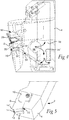
- Support d'outil de tournage (2) comprenant
un corps d'outil (4),
une plaquette d'outil de coupe (6),
une cale (8), et
un agencement de serrage (10), où
le corps d'outil (4) comprend un évidement (18), la cale (8) étant agencée au niveau d'une partie inférieure de l'évidement (18) et la plaquette d'outil de coupe (6) étant serrée de manière libérable par l'agencement de serrage (10) contre la cale (8), et où
un système de conduit de réfrigérant s'étend à travers le support d'outil de tournage (2), une première partie du système de conduit de réfrigérant s'étendant à travers le corps d'outil (4) et une partie d'extrémité du système de conduit de réfrigérant s'étendant à travers la cale (8),
caractérisé en ce que
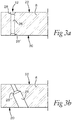
la partie d'extrémité du système de conduit de réfrigérant comprend un trou traversant (26) s'étendant depuis une première surface (20) de la cale (8) faisant face à un fond de l'évidement (18) jusqu'à une deuxième surface opposée (22) de la cale (8), où
la partie d'extrémité comprend une ouverture de sortie de réfrigérant (12) au niveau de la deuxième surface (22), l'ouverture de sortie de réfrigérant (12) étant formée par la cale (8) seule, et où
la cale (8) et l'ouverture de sortie de réfrigérant (12) sont configurées pour orienter un jet de réfrigérant depuis l'ouverture de sortie de réfrigérant (12) non obstruée par la plaquette d'outil de coupe (6) en direction d'un espace censé comprendre une zone de coupe d'une pièce d'ouvrage. - Support d'outil de tournage (2) selon la revendication 1, dans lequel une partie latérale (24) de la cale (8) s'étend au-delà d'un corps (50) de la plaquette d'outil de coupe (6), et où l'ouverture de sortie de réfrigérant (12) est prévue au niveau de la deuxième surface (22) dans la partie latérale (24).
- Support d'outil de tournage (2) selon la revendication 1 ou 2, dans lequel le trou traversant (26) présente un diamètre uniforme sensiblement sur toute son étendue à travers la cale (8).
- Support d'outil de tournage (2) selon la revendication 1 ou 2, dans lequel le trou traversant (26) comprend au moins une partie conique (28, 28', 28").
- Support d'outil de tournage (2) selon l'une quelconque des revendications précédentes, dans lequel une section (30) de la première partie du système de conduit de réfrigérant adjacente à la partie d'extrémité est formée par la cale (8) et un creux (32) dans le corps d'outil (4) dans la partie inférieure de l'évidement (18).
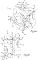
- Support d'outil de tournage (2) selon la revendication 5, dans lequel la première partie du système de conduit de réfrigérant comprend une partie de conduit droite (34) et un passage de distribution de réfrigérant (36) dans le corps d'outil (4), et où la partie de conduit droite (34) s'étend depuis le creux (32) jusqu'au passage de distribution de réfrigérant (36).
- Support d'outil de tournage (2) selon la revendication 6, dans lequel le creux (32) comprend une surface (35) s'étendant sensiblement perpendiculairement à la partie de conduit droite (34).
- Support d'outil de tournage (2) selon la revendication 6 ou 7, dans lequel la partie de conduit droite (34) s'étend à un angle aigu par rapport à un plan s'étendant le long de la partie inférieure de l'évidement (18) et de la cale (8).
- Support d'outil de tournage (2) selon l'une quelconque des revendications 6 à 8, dans lequel la partie d'extrémité présente un premier diamètre et la partie de conduit droite (34) présente un deuxième diamètre, et où le deuxième diamètre est supérieur ou égal au premier diamètre.
- Support d'outil de tournage (2) selon l'une quelconque des revendications 6 à 9, dans lequel le passage de distribution de réfrigérant (36) forme une partie d'entrée du système de conduit de réfrigérant comprenant un agencement de raccord (38) destiné à raccorder le système de conduit de réfrigérant à un système d'alimentation en réfrigérant d'un tour approprié.
- Support d'outil de tournage (2) selon l'une quelconque des revendications 6 à 10, dans lequel le passage de distribution de réfrigérant (36) s'étend dans une direction différente de celle de la partie de conduit droite (34).
- Support d'outil de tournage (2) selon l'une quelconque des revendications précédentes, dans lequel la cale (8) comprend une ouverture (40) permettant de fixer la cale (8) sur le corps d'outil (4), et où l'ouverture (40) est distincte du trou traversant (26).
- Support d'outil de tournage (2) selon l'une quelconque des revendications précédentes, dans lequel la plaquette d'outil de coupe (6) est une plaquette d'outil de coupe repositionnable huit fois (6).
- Support d'outil de tournage (2) selon la revendication 13, dans lequel
la plaquette d'outil de coupe (6) comprend un corps de plaquette (50), le corps de plaquette (50) comprenant deux surfaces de face parallèles opposées (52, 54) et quatre surfaces latérales mutuellement sensiblement identiques (56) s'étendant entre les surfaces de face (52, 54),
la plaquette d'outil de coupe (6) comprenant quatre arêtes de coupe distinctes (14) agencées symétriquement au niveau de chaque surface de face (52, 54), où
chaque arête de coupe distincte (14) comprend une première partie d'arête de coupe (58) s'étendant le long d'une partie de bordure d'une surface de face (52, 54) et une première partie d'arête de coupe (60) s'étendant le long d'une partie de bordure d'une surface latérale (56) dans un sens allant de la surface de face (52, 54) vers un plan milieu imaginaire (62) agencé entre les surfaces de face (52, 54) et parallèlement à celles-ci, la première partie d'arête de coupe (58) étant interconnectée à la première partie d'arête de coupe (60) via une partie d'arête de coin (64), où
selon une observation suivant une vue de côté le long d'un axe central (66), l'axe central (66) s'étendant perpendiculairement aux surfaces de face (52, 54), la plaquette d'outil de coupe (6) comprend un point de coin (68) au niveau de chacune des parties d'arête de coin (64), quatre des points de coin (68) étant agencés symétriquement au niveau de chacune des surfaces de face (52, 54) avec des distances de diagonale égales entre les points de coin (68), et où
un premier angle (δ) entre une première droite imaginaire (70) s'étendant depuis un premier point de coin (68') vers un deuxième point de coin (68") parmi deux points de coin adjacents (68, 68', 68") au niveau d'une seule surface de face (52, 54) et une deuxième droite imaginaire (72) s'étendant le long d'une partie de pointe (74) de la première partie d'arête de coupe (58) au niveau du premier point de coin (68) se situe dans une plage de 15 à 25 degrés. - Support d'outil de tournage (2) selon la revendication 14, dans lequel selon une observation suivant une vue de côté le long de l'axe central (66), un deuxième angle (β) d'environ 17 degrés est formé entre une troisième droite imaginaire (76) s'étendant depuis l'axe central (66) vers l'un des points de coin (68) au niveau d'une première surface de face (52) parmi les surfaces de face (52, 54) et une quatrième droite imaginaire (78) s'étendant depuis l'axe central (66) vers un point de coin adjacent (68) parmi les points de coin (68) au niveau d'une deuxième surface de face (54) parmi les surfaces de face (52, 54).
- Plaquette d'outil de coupe (6) conçue pour être utilisée dans un support d'outil de tournage (2) selon l'une quelconque des revendications précédentes, où la plaquette d'outil de coupe (6) est une plaquette d'outil de coupe repositionnable huit fois (6) comprenant un corps de plaquette (50), le corps de plaquette (50) comprenant deux surfaces de face parallèles opposées (52, 54) et quatre surfaces latérales mutuellement sensiblement identiques (56) s'étendant entre les surfaces de face (52, 54),
la plaquette d'outil de coupe (6) comprenant en outre quatre arêtes de coupe distinctes (14) agencées symétriquement au niveau de chaque surface de face (52, 54), où
chaque arête de coupe distincte comprend une première partie d'arête de coupe (58) s'étendant le long d'une partie de bordure d'une surface de face (52, 54) et une première partie d'arête de coupe (60) s'étendant le long d'une partie de bordure d'une surface latérale (56) dans un sens allant de la surface de face (52, 54) vers un plan milieu imaginaire (62) agencé entre les surfaces de face (52, 54) et parallèlement à celles-ci, la première partie d'arête de coupe (58) étant interconnectée à la première partie d'arête de coupe (60) via une partie d'arête de coin (64), où
selon une observation suivant une vue de côté le long d'un axe central (66), l'axe central (66) s'étendant perpendiculairement aux surfaces de face (52, 54), la plaquette d'outil de coupe (6) comprend un point de coin (68) au niveau de chacune des parties d'arête de coin (64), quatre des points de coin (68) étant agencés symétriquement au niveau de chacune des surfaces de face (52, 54) avec des distances de diagonale égales entre les points de coin (68), et caractérisée en ce que
un premier angle (δ) entre une première droite imaginaire s'étendant depuis un premier point de coin (68') vers un deuxième point de coin (68") parmi deux points de coin adjacents (68, 68', 68") au niveau d'une seule surface de face (52, 54) et une deuxième droite imaginaire (72) s'étendant le long d'une partie de pointe de la première partie d'arête de coupe (58) au niveau du premier point de coin (68) se situe dans une plage de 15 à 25 degrés. - Plaquette d'outil de coupe (6) selon la revendication 16, dans laquelle selon une observation suivant une vue de côté le long de l'axe central (66), un deuxième angle (β) d'environ 17 degrés est formé entre une troisième droite imaginaire (76) s'étendant depuis l'axe central (66) vers l'un des points de coin (68) au niveau d'une première surface de face (52) parmi les surfaces de face (52, 54) et une quatrième droite imaginaire (78) s'étendant depuis l'axe central (66) vers un point de coin adjacent (68) parmi les points de coin (68) au niveau d'une deuxième surface de face (54) parmi les surfaces de face (52, 54).
Priority Applications (7)
| Application Number | Priority Date | Filing Date | Title |
|---|---|---|---|
| EP14168809.3A EP2946857B1 (fr) | 2014-05-19 | 2014-05-19 | Support d'outil de tournage et insert d'outil de coupe |
| JP2015080547A JP6499492B2 (ja) | 2014-05-19 | 2015-04-10 | 旋削工具ホルダ及び切削インサート |
| CN201510186002.9A CN105081376B (zh) | 2014-05-19 | 2015-04-20 | 车刀刀架和切削刀具刀片 |
| BR102015011228-9A BR102015011228B1 (pt) | 2014-05-19 | 2015-05-15 | suporte de ferramenta de torneamento e pastilha de ferramenta de corte |
| KR1020150068040A KR102334778B1 (ko) | 2014-05-19 | 2015-05-15 | 선삭 공구 홀더 및 절삭 공구 인서트 |
| US14/715,447 US9925596B2 (en) | 2014-05-19 | 2015-05-18 | Turning tool holder and cutting tool insert |
| RU2015118561A RU2675130C2 (ru) | 2014-05-19 | 2015-05-18 | Токарный инструмент и режущая пластина |
Applications Claiming Priority (1)
| Application Number | Priority Date | Filing Date | Title |
|---|---|---|---|
| EP14168809.3A EP2946857B1 (fr) | 2014-05-19 | 2014-05-19 | Support d'outil de tournage et insert d'outil de coupe |
Publications (2)
| Publication Number | Publication Date |
|---|---|
| EP2946857A1 EP2946857A1 (fr) | 2015-11-25 |
| EP2946857B1 true EP2946857B1 (fr) | 2019-10-16 |
Family
ID=50729416
Family Applications (1)
| Application Number | Title | Priority Date | Filing Date |
|---|---|---|---|
| EP14168809.3A Active EP2946857B1 (fr) | 2014-05-19 | 2014-05-19 | Support d'outil de tournage et insert d'outil de coupe |
Country Status (7)
| Country | Link |
|---|---|
| US (1) | US9925596B2 (fr) |
| EP (1) | EP2946857B1 (fr) |
| JP (1) | JP6499492B2 (fr) |
| KR (1) | KR102334778B1 (fr) |
| CN (1) | CN105081376B (fr) |
| BR (1) | BR102015011228B1 (fr) |
| RU (1) | RU2675130C2 (fr) |
Families Citing this family (25)
| Publication number | Priority date | Publication date | Assignee | Title |
|---|---|---|---|---|
| DE102012108752B3 (de) | 2012-09-18 | 2014-01-23 | Hartmetall-Werkzeugfabrik Paul Horn Gmbh | Schneideinsatz und Werkzeug zur spanenden Bearbeitung eines Werkstücks |
| DE102012108751A1 (de) * | 2012-09-18 | 2014-03-20 | Hartmetall-Werkzeugfabrik Paul Horn Gmbh | Schneideinsatz und Werkzeug zur spanenden Bearbeitung eines Werkstücks |
| EP2946858B1 (fr) * | 2014-05-19 | 2019-07-10 | Sandvik Intellectual Property AB | Insert d'outil de coupe porte-outil de coupe |
| JP6550759B2 (ja) * | 2015-01-23 | 2019-07-31 | 三菱マテリアル株式会社 | バイト |
| EP3112066B1 (fr) * | 2015-07-03 | 2023-09-27 | Sandvik Intellectual Property AB | Outil, insert de coupe et partie de poudre compactée |
| CN108472736B (zh) * | 2016-01-29 | 2021-01-15 | 山高刀具公司 | 切削刀具 |
| JP6874292B2 (ja) * | 2016-07-21 | 2021-05-19 | 三菱マテリアル株式会社 | バイト |
| JP2018027605A (ja) * | 2016-08-19 | 2018-02-22 | 住友電工ハードメタル株式会社 | 切削工具用敷板および切削工具 |
| CN109562458B (zh) * | 2016-08-22 | 2020-09-01 | 京瓷株式会社 | 切削工具用刀架及切削工具、以及使用它们的切削加工物的制造方法 |
| US10201862B2 (en) * | 2016-09-07 | 2019-02-12 | Iscar, Ltd. | Cutting tool having a coolant chamber with an integrally formed coolant deflection portion and tool body |
| EP3330024B1 (fr) | 2016-12-01 | 2021-04-28 | Seco Tools Ab | Outil de coupe avec cale ayant un passage courbé et procédé de fabrication d'un tel outil |
| TWI640376B (zh) * | 2017-06-30 | 2018-11-11 | 黃憲仁 | 車刀架的改良結構 |
| DE102017122054A1 (de) | 2017-09-22 | 2019-03-28 | Kennametal Inc. | Schneidwerkzeug sowie Verfahren zur Herstellung eines Schneidwerkzeugs |
| CN109570629B (zh) * | 2017-09-28 | 2020-09-25 | 株式会社泰珂洛 | 切削工具 |
| WO2019107204A1 (fr) * | 2017-11-28 | 2019-06-06 | 京セラ株式会社 | Outil de coupe et procédé de fabrication d'un article coupé |
| DE102018100783A1 (de) | 2018-01-15 | 2019-07-18 | Kennametal Inc. | Drehwerkzeughalter sowie Drehwerkzeug |
| CN108031876A (zh) * | 2018-01-31 | 2018-05-15 | 张伟东 | 一种切削刀具 |
| EP3539696B1 (fr) * | 2018-03-13 | 2023-10-11 | AB Sandvik Coromant | Outil pour le tournage de métal comprenant un canal de refroidissement |
| US10953471B2 (en) * | 2018-04-16 | 2021-03-23 | Iscar, Ltd. | External turning tool having a cutting portion with a transverse elongated damping mechanism |
| JP6687200B2 (ja) * | 2018-04-24 | 2020-04-22 | 住友電工ハードメタル株式会社 | 切削工具用敷板および切削工具 |
| WO2020017011A1 (fr) * | 2018-07-19 | 2020-01-23 | 株式会社Fuji | Dispositif de déplacement |
| DE102019127027A1 (de) | 2019-10-08 | 2021-04-08 | Kennametal Inc. | Schneidwerkzeug |
| US11590587B2 (en) | 2020-04-16 | 2023-02-28 | Allied Machine & Engineering Corporation | Drill systems with coolant delivery arrangements and methods |
| JP6974808B1 (ja) * | 2021-02-10 | 2021-12-01 | 株式会社タンガロイ | 切削インサート |
| JP6972513B1 (ja) * | 2021-02-10 | 2021-11-24 | 株式会社タンガロイ | 切削インサート |
Citations (31)
| Publication number | Priority date | Publication date | Assignee | Title |
|---|---|---|---|---|
| US3490117A (en) | 1967-01-20 | 1970-01-20 | Karl Hertel | Tool holder |
| DE1602795A1 (de) | 1967-03-01 | 1970-04-09 | Hertel Karl | Schneidkoerper und zugehoeriges Klemmwerkzeug |
| FR1593553A (fr) | 1968-06-14 | 1970-06-01 | ||
| US4074949A (en) | 1975-09-19 | 1978-02-21 | Robert Zapp, Werkzeug-Und Maschinenfabrik Gmbh | Cutting tool |
| EP0042237A1 (fr) | 1980-06-16 | 1981-12-23 | Carmet Company | Outil de coupe et plaquette de coupe pour celui-ci |
| DE3033626A1 (de) | 1980-09-06 | 1982-04-22 | Karl Gustav Dipl.-Ing. 8500 Nürnberg Hertel jun. | Drehmeissel |
| EP0100376A2 (fr) | 1982-08-04 | 1984-02-15 | Rockwell International Corporation | Outil pour l'usinage des métaux |
| DE3004166C2 (fr) | 1979-02-07 | 1988-07-21 | Sandvik Ab, Sandviken, Se | |
| JPH0685712A (ja) | 1992-09-04 | 1994-03-25 | Sony Corp | アンテナ共用装置 |
| US5439327A (en) | 1991-09-27 | 1995-08-08 | Iscar Ltd. | Metal cutting tool |
| JPH0825111A (ja) | 1994-07-08 | 1996-01-30 | Toshiba Tungaloy Co Ltd | 旋削工具 |
| JPH1076404A (ja) | 1996-02-28 | 1998-03-24 | Sumitomo Electric Ind Ltd | 旋削用バイト |
| JP2003266207A (ja) | 2002-03-14 | 2003-09-24 | Ngk Spark Plug Co Ltd | バイト |
| US6705805B2 (en) | 2001-02-27 | 2004-03-16 | Sandvik Aktiebolag | Chip removing machining of a workpiece while applying high pressure cooling liquid |
| US20040240949A1 (en) | 2003-05-30 | 2004-12-02 | Pachao-Morbitzer Nelson M. | Threading insert with cooling channels |
| JP2006055916A (ja) | 2004-08-17 | 2006-03-02 | Tungaloy Corp | スローアウェイ式バイト |
| US20070292219A1 (en) | 2006-06-20 | 2007-12-20 | Craig Karen A | Indexable cutting insert with positive axial rake angle and multiple cutting edges |
| JP2008018515A (ja) | 2006-07-14 | 2008-01-31 | Mitsubishi Materials Corp | 切削インサート及び切削工具 |
| US20080175677A1 (en) | 2007-01-18 | 2008-07-24 | Prichard Paul D | Milling cutter and milling insert with coolant delivery |
| WO2009075634A1 (fr) | 2007-12-13 | 2009-06-18 | Seco Tools Ab | Plaquette de coupe et outil d'usinage par enlèvement de copeaux |
| US7634957B2 (en) | 2004-09-16 | 2009-12-22 | Air Products And Chemicals, Inc. | Method and apparatus for machining workpieces having interruptions |
| US20100129166A1 (en) | 2007-05-14 | 2010-05-27 | Kennametal Inc. | Eight-Edged Cutting Insert, and Tool Holder for Same |
| US7922427B2 (en) | 2008-12-18 | 2011-04-12 | Kennametal Inc. | Toolholder and toolholder assembly with elongated seating pads |
| US20120057942A1 (en) | 2007-01-18 | 2012-03-08 | Kennametal Inc. | Metal cutting system for effective coolant delivery |
| US8215878B2 (en) | 2009-04-22 | 2012-07-10 | Creare Incorporated | Indirect cooling of a rotary cutting tool |
| US20130051934A1 (en) | 2010-09-02 | 2013-02-28 | Kennametal lnc. | Cutting insert assembly and components thereof |
| DE112011102902T5 (de) | 2010-09-01 | 2013-06-06 | Kennametal Inc. | Scheibe für einen Schneideinsatz und Schneideinsatz-Scheiben-Anordnung mit interner Kühlmittelabgabe |
| US20140037390A1 (en) | 2011-08-14 | 2014-02-06 | Iscar, Ltd. | Apparatus and method for manufacturing cutting inserts |
| US20140064864A1 (en) | 2012-08-28 | 2014-03-06 | Kennametal Inc. | Tangential indexable cutting insert |
| WO2014033549A2 (fr) | 2012-08-28 | 2014-03-06 | Kennametal Inc. | Porte-outil pour insert de coupe tangentiel |
| JP2014046446A (ja) | 2012-09-04 | 2014-03-17 | Ngk Spark Plug Co Ltd | 切削工具用ホルダ及び切削工具 |
Family Cites Families (29)
| Publication number | Priority date | Publication date | Assignee | Title |
|---|---|---|---|---|
| SU471952A2 (ru) * | 1973-09-19 | 1975-05-30 | Резец | |
| SU588099A1 (ru) * | 1975-01-14 | 1978-01-15 | Проектно-Конструкторский Технологический Институт | Устройство дл охлпждени зоны резани |
| SU1060322A1 (ru) * | 1982-03-05 | 1983-12-15 | Сестрорецкий Инструментальный Завод Им.Воскова | Режуща пластина |
| US4535216A (en) * | 1983-10-14 | 1985-08-13 | Rockwell International Corporation | Metal-working tool using electrical heating |
| RU2005577C1 (ru) * | 1990-12-19 | 1994-01-15 | Таганрогский Радиотехнический Институт | Режущий инструмент |
| US5775854A (en) * | 1991-09-27 | 1998-07-07 | Iscar Ltd. | Metal cutting tool |
| JPH0839387A (ja) * | 1994-07-29 | 1996-02-13 | Mitsubishi Materials Corp | スローアウェイチップおよびこれを用いたフライスカッタ |
| JP2001287103A (ja) * | 2000-04-06 | 2001-10-16 | Seiko Epson Corp | 切削加工装置 |
| IL153252A0 (en) * | 2002-06-04 | 2003-07-06 | Iscar Ltd | Tangential cutting insert and milling cutter |
| US7094007B2 (en) * | 2002-12-04 | 2006-08-22 | Iscar Ltd. | Tangential cutting insert and milling cutter |
| IL158098A (en) * | 2003-09-24 | 2008-03-20 | Amir Satran | Tangential cutting insert and milling cutter |
| JP2006088297A (ja) * | 2004-09-27 | 2006-04-06 | Kobe Univ | 切削加工装置および切削加工方法 |
| JP2006136953A (ja) * | 2004-11-10 | 2006-06-01 | Tokyo Institute Of Technology | 最少量潤滑切削工具、最少量潤滑切削装置および最少量潤滑切削方法 |
| US7273331B2 (en) * | 2004-12-29 | 2007-09-25 | Giannetti Enrico R | Boring bar having internal coolant supply |
| DE102005054434B4 (de) * | 2005-11-15 | 2009-09-24 | Kennametal Inc. | Wendeschneidplatte mit zwei Teilkörpern |
| US8454274B2 (en) | 2007-01-18 | 2013-06-04 | Kennametal Inc. | Cutting inserts |
| IL182100A (en) * | 2007-03-21 | 2010-11-30 | Taegutec India Ltd | Cutting insert for a milling cutter |
| DE102007022535A1 (de) * | 2007-05-14 | 2008-11-20 | Kennametal Inc. | Achtschneidiger Schneideinsatz sowie Werkzeughalter hierfür |
| RU2350432C1 (ru) * | 2007-09-05 | 2009-03-27 | Нина Алексеевна Корюкина | Тангенциальная режущая пластина |
| US8454277B2 (en) * | 2008-12-18 | 2013-06-04 | Kennametal Inc. | Toolholder and toolholder assembly with elongated seating pads |
| SE533017C2 (sv) * | 2009-02-20 | 2010-06-08 | Seco Tools Ab | Skärverktyg och skär med fluidströmningsstrukturer |
| IL197898A0 (en) * | 2009-04-05 | 2009-12-24 | Iscar Ltd | Cutting insert and cutting tool therefor |
| US8061241B2 (en) * | 2009-04-06 | 2011-11-22 | Creare Incorporated | Indirect cooling of a cutting tool |
| US8596935B2 (en) * | 2010-10-08 | 2013-12-03 | TDY Industries, LLC | Cutting tools and cutting inserts including internal cooling |
| IL210966A (en) * | 2011-01-31 | 2015-06-30 | Iscar Ltd | Tangential and milling |
| EP2596889B1 (fr) * | 2011-11-23 | 2017-04-26 | Sandvik Intellectual Property AB | Plaquette de coupe et fraise |
| US9511421B2 (en) * | 2013-06-14 | 2016-12-06 | Kennametal Inc. | Cutting tool assembly having clamp assembly comprising a clamp and a coolant plate |
| EP2946858B1 (fr) * | 2014-05-19 | 2019-07-10 | Sandvik Intellectual Property AB | Insert d'outil de coupe porte-outil de coupe |
| US10046398B2 (en) * | 2014-12-15 | 2018-08-14 | Seco Tools Ab | Reinforced double-sided cutting insert and cutting tool with reinforced double-sided cutting insert |
-
2014
- 2014-05-19 EP EP14168809.3A patent/EP2946857B1/fr active Active
-
2015
- 2015-04-10 JP JP2015080547A patent/JP6499492B2/ja active Active
- 2015-04-20 CN CN201510186002.9A patent/CN105081376B/zh active Active
- 2015-05-15 KR KR1020150068040A patent/KR102334778B1/ko active IP Right Grant
- 2015-05-15 BR BR102015011228-9A patent/BR102015011228B1/pt active IP Right Grant
- 2015-05-18 RU RU2015118561A patent/RU2675130C2/ru active
- 2015-05-18 US US14/715,447 patent/US9925596B2/en active Active
Patent Citations (31)
| Publication number | Priority date | Publication date | Assignee | Title |
|---|---|---|---|---|
| US3490117A (en) | 1967-01-20 | 1970-01-20 | Karl Hertel | Tool holder |
| DE1602795A1 (de) | 1967-03-01 | 1970-04-09 | Hertel Karl | Schneidkoerper und zugehoeriges Klemmwerkzeug |
| FR1593553A (fr) | 1968-06-14 | 1970-06-01 | ||
| US4074949A (en) | 1975-09-19 | 1978-02-21 | Robert Zapp, Werkzeug-Und Maschinenfabrik Gmbh | Cutting tool |
| DE3004166C2 (fr) | 1979-02-07 | 1988-07-21 | Sandvik Ab, Sandviken, Se | |
| EP0042237A1 (fr) | 1980-06-16 | 1981-12-23 | Carmet Company | Outil de coupe et plaquette de coupe pour celui-ci |
| DE3033626A1 (de) | 1980-09-06 | 1982-04-22 | Karl Gustav Dipl.-Ing. 8500 Nürnberg Hertel jun. | Drehmeissel |
| EP0100376A2 (fr) | 1982-08-04 | 1984-02-15 | Rockwell International Corporation | Outil pour l'usinage des métaux |
| US5439327A (en) | 1991-09-27 | 1995-08-08 | Iscar Ltd. | Metal cutting tool |
| JPH0685712A (ja) | 1992-09-04 | 1994-03-25 | Sony Corp | アンテナ共用装置 |
| JPH0825111A (ja) | 1994-07-08 | 1996-01-30 | Toshiba Tungaloy Co Ltd | 旋削工具 |
| JPH1076404A (ja) | 1996-02-28 | 1998-03-24 | Sumitomo Electric Ind Ltd | 旋削用バイト |
| US6705805B2 (en) | 2001-02-27 | 2004-03-16 | Sandvik Aktiebolag | Chip removing machining of a workpiece while applying high pressure cooling liquid |
| JP2003266207A (ja) | 2002-03-14 | 2003-09-24 | Ngk Spark Plug Co Ltd | バイト |
| US20040240949A1 (en) | 2003-05-30 | 2004-12-02 | Pachao-Morbitzer Nelson M. | Threading insert with cooling channels |
| JP2006055916A (ja) | 2004-08-17 | 2006-03-02 | Tungaloy Corp | スローアウェイ式バイト |
| US7634957B2 (en) | 2004-09-16 | 2009-12-22 | Air Products And Chemicals, Inc. | Method and apparatus for machining workpieces having interruptions |
| US20070292219A1 (en) | 2006-06-20 | 2007-12-20 | Craig Karen A | Indexable cutting insert with positive axial rake angle and multiple cutting edges |
| JP2008018515A (ja) | 2006-07-14 | 2008-01-31 | Mitsubishi Materials Corp | 切削インサート及び切削工具 |
| US20120057942A1 (en) | 2007-01-18 | 2012-03-08 | Kennametal Inc. | Metal cutting system for effective coolant delivery |
| US20080175677A1 (en) | 2007-01-18 | 2008-07-24 | Prichard Paul D | Milling cutter and milling insert with coolant delivery |
| US20100129166A1 (en) | 2007-05-14 | 2010-05-27 | Kennametal Inc. | Eight-Edged Cutting Insert, and Tool Holder for Same |
| WO2009075634A1 (fr) | 2007-12-13 | 2009-06-18 | Seco Tools Ab | Plaquette de coupe et outil d'usinage par enlèvement de copeaux |
| US7922427B2 (en) | 2008-12-18 | 2011-04-12 | Kennametal Inc. | Toolholder and toolholder assembly with elongated seating pads |
| US8215878B2 (en) | 2009-04-22 | 2012-07-10 | Creare Incorporated | Indirect cooling of a rotary cutting tool |
| DE112011102902T5 (de) | 2010-09-01 | 2013-06-06 | Kennametal Inc. | Scheibe für einen Schneideinsatz und Schneideinsatz-Scheiben-Anordnung mit interner Kühlmittelabgabe |
| US20130051934A1 (en) | 2010-09-02 | 2013-02-28 | Kennametal lnc. | Cutting insert assembly and components thereof |
| US20140037390A1 (en) | 2011-08-14 | 2014-02-06 | Iscar, Ltd. | Apparatus and method for manufacturing cutting inserts |
| US20140064864A1 (en) | 2012-08-28 | 2014-03-06 | Kennametal Inc. | Tangential indexable cutting insert |
| WO2014033549A2 (fr) | 2012-08-28 | 2014-03-06 | Kennametal Inc. | Porte-outil pour insert de coupe tangentiel |
| JP2014046446A (ja) | 2012-09-04 | 2014-03-17 | Ngk Spark Plug Co Ltd | 切削工具用ホルダ及び切削工具 |
Non-Patent Citations (1)
| Title |
|---|
| ANONYMOUS: "New product news High Pressure Coolant tool", TAEGUTEC, 1 April 2014 (2014-04-01), pages 1 - 14, XP055790949 |
Also Published As
| Publication number | Publication date |
|---|---|
| JP2015217512A (ja) | 2015-12-07 |
| US9925596B2 (en) | 2018-03-27 |
| RU2675130C2 (ru) | 2018-12-17 |
| KR102334778B1 (ko) | 2021-12-02 |
| EP2946857A1 (fr) | 2015-11-25 |
| JP6499492B2 (ja) | 2019-04-10 |
| CN105081376A (zh) | 2015-11-25 |
| RU2015118561A (ru) | 2016-12-10 |
| BR102015011228A2 (pt) | 2017-07-18 |
| US20150328688A1 (en) | 2015-11-19 |
| KR20150133141A (ko) | 2015-11-27 |
| RU2015118561A3 (fr) | 2018-10-29 |
| BR102015011228B1 (pt) | 2021-02-17 |
| CN105081376B (zh) | 2018-09-18 |
Similar Documents
| Publication | Publication Date | Title |
|---|---|---|
| EP2946857B1 (fr) | Support d'outil de tournage et insert d'outil de coupe | |
| JP6550759B2 (ja) | バイト | |
| EP2682212B1 (fr) | Patin de guidage et outil de coupe | |
| EP3059034B1 (fr) | Porte-outil et outil de coupe | |
| KR102307031B1 (ko) | 일체 형성된 냉각제 편향부를 갖는 냉각 챔버 및 공구 몸체를 갖는 절삭 공구 | |
| US9676043B2 (en) | Slot milling disc and a rotatable mounting shaft for such a milling disc | |
| US10661352B2 (en) | Parting lathe tool | |
| KR102614838B1 (ko) | 절삭 공구 | |
| EP2718049B1 (fr) | Patin de support pour outil de coupe et outil de coupe avec un tel patin | |
| KR20110139218A (ko) | 절삭 유체를 팬과 유사한 패턴으로 제공하는 냉각제 전달 시스템을 구비한 절삭 공구 | |
| JP2021030385A (ja) | 刃先交換式クーラント孔付きエンドミルのエンドミル本体および刃先交換式クーラント孔付きエンドミル | |
| CN108463302B (zh) | 金属切削刀具架和通过车削操作加工金属工件的方法 | |
| EP2682211A1 (fr) | Plot de guidage, corps d'outil de coupe et outil de coupe | |
| KR102647951B1 (ko) | 냉각제 채널을 포함하는 금속 절삭을 위한 선삭 공구 | |
| WO2018016412A1 (fr) | Outil de coupe | |
| JP2018012172A (ja) | バイト | |
| EP3199274B1 (fr) | Outil de découpage |
Legal Events
| Date | Code | Title | Description |
|---|---|---|---|
| PUAI | Public reference made under article 153(3) epc to a published international application that has entered the european phase |
Free format text: ORIGINAL CODE: 0009012 |
|
| AK | Designated contracting states |
Kind code of ref document: A1 Designated state(s): AL AT BE BG CH CY CZ DE DK EE ES FI FR GB GR HR HU IE IS IT LI LT LU LV MC MK MT NL NO PL PT RO RS SE SI SK SM TR |
|
| AX | Request for extension of the european patent |
Extension state: BA ME |
|
| 17P | Request for examination filed |
Effective date: 20160525 |
|
| RBV | Designated contracting states (corrected) |
Designated state(s): AL AT BE BG CH CY CZ DE DK EE ES FI FR GB GR HR HU IE IS IT LI LT LU LV MC MK MT NL NO PL PT RO RS SE SI SK SM TR |
|
| RIC1 | Information provided on ipc code assigned before grant |
Ipc: B23B 27/10 20060101AFI20190308BHEP Ipc: B23B 27/16 20060101ALI20190308BHEP |
|
| GRAP | Despatch of communication of intention to grant a patent |
Free format text: ORIGINAL CODE: EPIDOSNIGR1 |
|
| STAA | Information on the status of an ep patent application or granted ep patent |
Free format text: STATUS: GRANT OF PATENT IS INTENDED |
|
| INTG | Intention to grant announced |
Effective date: 20190619 |
|
| GRAS | Grant fee paid |
Free format text: ORIGINAL CODE: EPIDOSNIGR3 |
|
| GRAA | (expected) grant |
Free format text: ORIGINAL CODE: 0009210 |
|
| STAA | Information on the status of an ep patent application or granted ep patent |
Free format text: STATUS: THE PATENT HAS BEEN GRANTED |
|
| AK | Designated contracting states |
Kind code of ref document: B1 Designated state(s): AL AT BE BG CH CY CZ DE DK EE ES FI FR GB GR HR HU IE IS IT LI LT LU LV MC MK MT NL NO PL PT RO RS SE SI SK SM TR |
|
| REG | Reference to a national code |
Ref country code: GB Ref legal event code: FG4D |
|
| REG | Reference to a national code |
Ref country code: CH Ref legal event code: EP |
|
| REG | Reference to a national code |
Ref country code: DE Ref legal event code: R096 Ref document number: 602014055151 Country of ref document: DE |
|
| REG | Reference to a national code |
Ref country code: IE Ref legal event code: FG4D |
|
| REG | Reference to a national code |
Ref country code: AT Ref legal event code: REF Ref document number: 1190801 Country of ref document: AT Kind code of ref document: T Effective date: 20191115 |
|
| REG | Reference to a national code |
Ref country code: NL Ref legal event code: MP Effective date: 20191016 |
|
| REG | Reference to a national code |
Ref country code: LT Ref legal event code: MG4D |
|
| REG | Reference to a national code |
Ref country code: AT Ref legal event code: MK05 Ref document number: 1190801 Country of ref document: AT Kind code of ref document: T Effective date: 20191016 |
|
| PG25 | Lapsed in a contracting state [announced via postgrant information from national office to epo] |
Ref country code: ES Free format text: LAPSE BECAUSE OF FAILURE TO SUBMIT A TRANSLATION OF THE DESCRIPTION OR TO PAY THE FEE WITHIN THE PRESCRIBED TIME-LIMIT Effective date: 20191016 Ref country code: NL Free format text: LAPSE BECAUSE OF FAILURE TO SUBMIT A TRANSLATION OF THE DESCRIPTION OR TO PAY THE FEE WITHIN THE PRESCRIBED TIME-LIMIT Effective date: 20191016 Ref country code: AT Free format text: LAPSE BECAUSE OF FAILURE TO SUBMIT A TRANSLATION OF THE DESCRIPTION OR TO PAY THE FEE WITHIN THE PRESCRIBED TIME-LIMIT Effective date: 20191016 Ref country code: GR Free format text: LAPSE BECAUSE OF FAILURE TO SUBMIT A TRANSLATION OF THE DESCRIPTION OR TO PAY THE FEE WITHIN THE PRESCRIBED TIME-LIMIT Effective date: 20200117 Ref country code: PL Free format text: LAPSE BECAUSE OF FAILURE TO SUBMIT A TRANSLATION OF THE DESCRIPTION OR TO PAY THE FEE WITHIN THE PRESCRIBED TIME-LIMIT Effective date: 20191016 Ref country code: LT Free format text: LAPSE BECAUSE OF FAILURE TO SUBMIT A TRANSLATION OF THE DESCRIPTION OR TO PAY THE FEE WITHIN THE PRESCRIBED TIME-LIMIT Effective date: 20191016 Ref country code: PT Free format text: LAPSE BECAUSE OF FAILURE TO SUBMIT A TRANSLATION OF THE DESCRIPTION OR TO PAY THE FEE WITHIN THE PRESCRIBED TIME-LIMIT Effective date: 20200217 Ref country code: BG Free format text: LAPSE BECAUSE OF FAILURE TO SUBMIT A TRANSLATION OF THE DESCRIPTION OR TO PAY THE FEE WITHIN THE PRESCRIBED TIME-LIMIT Effective date: 20200116 Ref country code: FI Free format text: LAPSE BECAUSE OF FAILURE TO SUBMIT A TRANSLATION OF THE DESCRIPTION OR TO PAY THE FEE WITHIN THE PRESCRIBED TIME-LIMIT Effective date: 20191016 Ref country code: LV Free format text: LAPSE BECAUSE OF FAILURE TO SUBMIT A TRANSLATION OF THE DESCRIPTION OR TO PAY THE FEE WITHIN THE PRESCRIBED TIME-LIMIT Effective date: 20191016 Ref country code: SE Free format text: LAPSE BECAUSE OF FAILURE TO SUBMIT A TRANSLATION OF THE DESCRIPTION OR TO PAY THE FEE WITHIN THE PRESCRIBED TIME-LIMIT Effective date: 20191016 Ref country code: NO Free format text: LAPSE BECAUSE OF FAILURE TO SUBMIT A TRANSLATION OF THE DESCRIPTION OR TO PAY THE FEE WITHIN THE PRESCRIBED TIME-LIMIT Effective date: 20200116 |
|
| PG25 | Lapsed in a contracting state [announced via postgrant information from national office to epo] |
Ref country code: HR Free format text: LAPSE BECAUSE OF FAILURE TO SUBMIT A TRANSLATION OF THE DESCRIPTION OR TO PAY THE FEE WITHIN THE PRESCRIBED TIME-LIMIT Effective date: 20191016 Ref country code: RS Free format text: LAPSE BECAUSE OF FAILURE TO SUBMIT A TRANSLATION OF THE DESCRIPTION OR TO PAY THE FEE WITHIN THE PRESCRIBED TIME-LIMIT Effective date: 20191016 Ref country code: IS Free format text: LAPSE BECAUSE OF FAILURE TO SUBMIT A TRANSLATION OF THE DESCRIPTION OR TO PAY THE FEE WITHIN THE PRESCRIBED TIME-LIMIT Effective date: 20200224 |
|
| PG25 | Lapsed in a contracting state [announced via postgrant information from national office to epo] |
Ref country code: AL Free format text: LAPSE BECAUSE OF FAILURE TO SUBMIT A TRANSLATION OF THE DESCRIPTION OR TO PAY THE FEE WITHIN THE PRESCRIBED TIME-LIMIT Effective date: 20191016 |
|
| REG | Reference to a national code |
Ref country code: DE Ref legal event code: R026 Ref document number: 602014055151 Country of ref document: DE |
|
| PLBI | Opposition filed |
Free format text: ORIGINAL CODE: 0009260 |
|
| PLAX | Notice of opposition and request to file observation + time limit sent |
Free format text: ORIGINAL CODE: EPIDOSNOBS2 |
|
| PG2D | Information on lapse in contracting state deleted |
Ref country code: IS |
|
| PG25 | Lapsed in a contracting state [announced via postgrant information from national office to epo] |
Ref country code: RO Free format text: LAPSE BECAUSE OF FAILURE TO SUBMIT A TRANSLATION OF THE DESCRIPTION OR TO PAY THE FEE WITHIN THE PRESCRIBED TIME-LIMIT Effective date: 20191016 Ref country code: CZ Free format text: LAPSE BECAUSE OF FAILURE TO SUBMIT A TRANSLATION OF THE DESCRIPTION OR TO PAY THE FEE WITHIN THE PRESCRIBED TIME-LIMIT Effective date: 20191016 Ref country code: DK Free format text: LAPSE BECAUSE OF FAILURE TO SUBMIT A TRANSLATION OF THE DESCRIPTION OR TO PAY THE FEE WITHIN THE PRESCRIBED TIME-LIMIT Effective date: 20191016 Ref country code: EE Free format text: LAPSE BECAUSE OF FAILURE TO SUBMIT A TRANSLATION OF THE DESCRIPTION OR TO PAY THE FEE WITHIN THE PRESCRIBED TIME-LIMIT Effective date: 20191016 Ref country code: IS Free format text: LAPSE BECAUSE OF FAILURE TO SUBMIT A TRANSLATION OF THE DESCRIPTION OR TO PAY THE FEE WITHIN THE PRESCRIBED TIME-LIMIT Effective date: 20200216 |
|
| 26 | Opposition filed |
Opponent name: ISCAR LTD. Effective date: 20200716 |
|
| PG25 | Lapsed in a contracting state [announced via postgrant information from national office to epo] |
Ref country code: SM Free format text: LAPSE BECAUSE OF FAILURE TO SUBMIT A TRANSLATION OF THE DESCRIPTION OR TO PAY THE FEE WITHIN THE PRESCRIBED TIME-LIMIT Effective date: 20191016 Ref country code: SK Free format text: LAPSE BECAUSE OF FAILURE TO SUBMIT A TRANSLATION OF THE DESCRIPTION OR TO PAY THE FEE WITHIN THE PRESCRIBED TIME-LIMIT Effective date: 20191016 |
|
| PLBB | Reply of patent proprietor to notice(s) of opposition received |
Free format text: ORIGINAL CODE: EPIDOSNOBS3 |
|
| PG25 | Lapsed in a contracting state [announced via postgrant information from national office to epo] |
Ref country code: SI Free format text: LAPSE BECAUSE OF FAILURE TO SUBMIT A TRANSLATION OF THE DESCRIPTION OR TO PAY THE FEE WITHIN THE PRESCRIBED TIME-LIMIT Effective date: 20191016 |
|
| PG25 | Lapsed in a contracting state [announced via postgrant information from national office to epo] |
Ref country code: LI Free format text: LAPSE BECAUSE OF NON-PAYMENT OF DUE FEES Effective date: 20200531 Ref country code: CH Free format text: LAPSE BECAUSE OF NON-PAYMENT OF DUE FEES Effective date: 20200531 Ref country code: MC Free format text: LAPSE BECAUSE OF FAILURE TO SUBMIT A TRANSLATION OF THE DESCRIPTION OR TO PAY THE FEE WITHIN THE PRESCRIBED TIME-LIMIT Effective date: 20191016 |
|
| REG | Reference to a national code |
Ref country code: BE Ref legal event code: MM Effective date: 20200531 |
|
| PG25 | Lapsed in a contracting state [announced via postgrant information from national office to epo] |
Ref country code: LU Free format text: LAPSE BECAUSE OF NON-PAYMENT OF DUE FEES Effective date: 20200519 |
|
| PG25 | Lapsed in a contracting state [announced via postgrant information from national office to epo] |
Ref country code: IE Free format text: LAPSE BECAUSE OF NON-PAYMENT OF DUE FEES Effective date: 20200519 |
|
| PG25 | Lapsed in a contracting state [announced via postgrant information from national office to epo] |
Ref country code: BE Free format text: LAPSE BECAUSE OF NON-PAYMENT OF DUE FEES Effective date: 20200531 |
|
| REG | Reference to a national code |
Ref country code: DE Ref legal event code: R100 Ref document number: 602014055151 Country of ref document: DE |
|
| PLCK | Communication despatched that opposition was rejected |
Free format text: ORIGINAL CODE: EPIDOSNREJ1 |
|
| PLBN | Opposition rejected |
Free format text: ORIGINAL CODE: 0009273 |
|
| STAA | Information on the status of an ep patent application or granted ep patent |
Free format text: STATUS: OPPOSITION REJECTED |
|
| PG25 | Lapsed in a contracting state [announced via postgrant information from national office to epo] |
Ref country code: TR Free format text: LAPSE BECAUSE OF FAILURE TO SUBMIT A TRANSLATION OF THE DESCRIPTION OR TO PAY THE FEE WITHIN THE PRESCRIBED TIME-LIMIT Effective date: 20191016 Ref country code: MT Free format text: LAPSE BECAUSE OF FAILURE TO SUBMIT A TRANSLATION OF THE DESCRIPTION OR TO PAY THE FEE WITHIN THE PRESCRIBED TIME-LIMIT Effective date: 20191016 Ref country code: CY Free format text: LAPSE BECAUSE OF FAILURE TO SUBMIT A TRANSLATION OF THE DESCRIPTION OR TO PAY THE FEE WITHIN THE PRESCRIBED TIME-LIMIT Effective date: 20191016 |
|
| 27O | Opposition rejected |
Effective date: 20220121 |
|
| PG25 | Lapsed in a contracting state [announced via postgrant information from national office to epo] |
Ref country code: MK Free format text: LAPSE BECAUSE OF FAILURE TO SUBMIT A TRANSLATION OF THE DESCRIPTION OR TO PAY THE FEE WITHIN THE PRESCRIBED TIME-LIMIT Effective date: 20191016 |
|
| P01 | Opt-out of the competence of the unified patent court (upc) registered |
Effective date: 20230603 |
|
| PGFP | Annual fee paid to national office [announced via postgrant information from national office to epo] |
Ref country code: IT Payment date: 20230412 Year of fee payment: 10 Ref country code: FR Payment date: 20230421 Year of fee payment: 10 Ref country code: DE Payment date: 20230404 Year of fee payment: 10 |
|
| PGFP | Annual fee paid to national office [announced via postgrant information from national office to epo] |
Ref country code: GB Payment date: 20230406 Year of fee payment: 10 |