US10661352B2 - Parting lathe tool - Google Patents
Parting lathe tool Download PDFInfo
- Publication number
- US10661352B2 US10661352B2 US15/971,055 US201815971055A US10661352B2 US 10661352 B2 US10661352 B2 US 10661352B2 US 201815971055 A US201815971055 A US 201815971055A US 10661352 B2 US10661352 B2 US 10661352B2
- Authority
- US
- United States
- Prior art keywords
- coolant
- lathe tool
- parting lathe
- parting
- supply port
- Prior art date
- Legal status (The legal status is an assumption and is not a legal conclusion. Google has not performed a legal analysis and makes no representation as to the accuracy of the status listed.)
- Active
Links
- 239000002826 coolant Substances 0.000 claims abstract description 262
- 238000005520 cutting process Methods 0.000 claims abstract description 67
- 238000003754 machining Methods 0.000 claims abstract description 9
- 239000002184 metal Substances 0.000 claims abstract description 6
- 238000004519 manufacturing process Methods 0.000 claims description 20
- 238000001816 cooling Methods 0.000 description 7
- 230000000694 effects Effects 0.000 description 4
- 239000005068 cooling lubricant Substances 0.000 description 2
- 238000000034 method Methods 0.000 description 2
- 239000000463 material Substances 0.000 description 1
- 230000003313 weakening effect Effects 0.000 description 1
Images


Classifications
-
- B—PERFORMING OPERATIONS; TRANSPORTING
- B23—MACHINE TOOLS; METAL-WORKING NOT OTHERWISE PROVIDED FOR
- B23B—TURNING; BORING
- B23B27/00—Tools for turning or boring machines; Tools of a similar kind in general; Accessories therefor
- B23B27/10—Cutting tools with special provision for cooling
-
- B—PERFORMING OPERATIONS; TRANSPORTING
- B23—MACHINE TOOLS; METAL-WORKING NOT OTHERWISE PROVIDED FOR
- B23B—TURNING; BORING
- B23B27/00—Tools for turning or boring machines; Tools of a similar kind in general; Accessories therefor
- B23B27/04—Cutting-off tools
-
- B—PERFORMING OPERATIONS; TRANSPORTING
- B23—MACHINE TOOLS; METAL-WORKING NOT OTHERWISE PROVIDED FOR
- B23B—TURNING; BORING
- B23B27/00—Tools for turning or boring machines; Tools of a similar kind in general; Accessories therefor
- B23B27/08—Cutting tools with blade- or disc-like main parts
- B23B27/083—Cutting tools with disc-like main parts
-
- B—PERFORMING OPERATIONS; TRANSPORTING
- B23—MACHINE TOOLS; METAL-WORKING NOT OTHERWISE PROVIDED FOR
- B23B—TURNING; BORING
- B23B27/00—Tools for turning or boring machines; Tools of a similar kind in general; Accessories therefor
- B23B27/08—Cutting tools with blade- or disc-like main parts
- B23B27/086—Cutting tools with blade- or disc-like main parts with yieldable support for the cutting insert
-
- B—PERFORMING OPERATIONS; TRANSPORTING
- B23—MACHINE TOOLS; METAL-WORKING NOT OTHERWISE PROVIDED FOR
- B23B—TURNING; BORING
- B23B29/00—Holders for non-rotary cutting tools; Boring bars or boring heads; Accessories for tool holders
- B23B29/04—Tool holders for a single cutting tool
- B23B29/043—Tool holders for a single cutting tool with cutting-off, grooving or profile cutting tools, i.e. blade- or disc-like main cutting parts
-
- B—PERFORMING OPERATIONS; TRANSPORTING
- B23—MACHINE TOOLS; METAL-WORKING NOT OTHERWISE PROVIDED FOR
- B23B—TURNING; BORING
- B23B2200/00—Details of cutting inserts
- B23B2200/36—Other features of cutting inserts not covered by B23B2200/04 - B23B2200/32
- B23B2200/3627—Indexing
-
- B—PERFORMING OPERATIONS; TRANSPORTING
- B23—MACHINE TOOLS; METAL-WORKING NOT OTHERWISE PROVIDED FOR
- B23B—TURNING; BORING
- B23B2250/00—Compensating adverse effects during turning, boring or drilling
- B23B2250/12—Cooling and lubrication
-
- B—PERFORMING OPERATIONS; TRANSPORTING
- B23—MACHINE TOOLS; METAL-WORKING NOT OTHERWISE PROVIDED FOR
- B23B—TURNING; BORING
- B23B2260/00—Details of constructional elements
- B23B2260/078—Hand tools used to operate chucks or to assemble, adjust or disassemble tools or equipment used for turning, boring or drilling
- B23B2260/0785—Hand tools used to operate chucks or to assemble, adjust or disassemble tools or equipment used for turning, boring or drilling for unclamping cutting inserts
-
- B—PERFORMING OPERATIONS; TRANSPORTING
- B23—MACHINE TOOLS; METAL-WORKING NOT OTHERWISE PROVIDED FOR
- B23Q—DETAILS, COMPONENTS, OR ACCESSORIES FOR MACHINE TOOLS, e.g. ARRANGEMENTS FOR COPYING OR CONTROLLING; MACHINE TOOLS IN GENERAL CHARACTERISED BY THE CONSTRUCTION OF PARTICULAR DETAILS OR COMPONENTS; COMBINATIONS OR ASSOCIATIONS OF METAL-WORKING MACHINES, NOT DIRECTED TO A PARTICULAR RESULT
- B23Q11/00—Accessories fitted to machine tools for keeping tools or parts of the machine in good working condition or for cooling work; Safety devices specially combined with or arranged in, or specially adapted for use in connection with, machine tools
- B23Q11/10—Arrangements for cooling or lubricating tools or work
Definitions
- the invention relates to a parting lathe tool for machining metal, with a clamping seat for receiving a cutting insert and with an internal coolant supply system for supplying a cutting zone with coolant comprising at least one coolant line running in the parting lathe tool.
- Parting lathe tools are known in the prior art. They are used for severing workpieces clamped in a lathe. Parting lathe tools can also be used for producing grooves. For this purpose, these tools are available in different widths, which usually correspond to a groove width to be produced.
- coolant supply systems are known by means of which a cutting zone and tool parts close to the cutting zone can be cooled.
- cutting edges and other tool parts in direct contact with the workpiece are hereby cooled.
- a cutting tool is normally supplied with coolant or cooling lubricant via an internal cooling system within the lathe which usually provides a fixed coolant pressure.
- parting lathe tools do however have the problem that they are particularly flat, especially in the areas to be cooled. For this reason, the coolant lines running within a parting lathe tool are subject to geometrically narrow limits. This applies in particular to the feasible cross-sections of the coolant lines. This means that the supply of coolant to a cutting zone is limited.
- the object of the invention is to further improve a parting lathe tool of the aforementioned type.
- a parting lathe tool is presented which has particularly good cutting properties.
- the coolant supply system has at least three coolant outlets, wherein the coolant outlets are fluidically connected to a coolant supply port via at least two separate coolant lines running within the parting lathe tool.
- the coolant lines To each of the coolant lines, one or more coolant outlets are thus assigned.
- the assigned coolant outlets are supplied with coolant via the coolant line.
- the coolant line fluidically connects the coolant outlets assigned to it to the coolant supply port.
- Separate coolant lines means that along their entire length the coolant lines do not share any line sections, that is, from the coolant supply port as far as the coolant outlets assigned to the coolant line.
- the parting lathe tool can also be referred to as a cutting lathe tool or a grooving tool.
- coolant will also be taken to include cooling lubricant.
- the coolant supply port represents the coolant inlet of the internal coolant supply system of the parting lathe tool.
- the parting lathe tool preferably only comprises one coolant supply port. However, if so required, several can also be used.
- the coolant supply port preferably takes the form of a hole or slot.
- other geometries are also possible.
- the cross-sections of coolant lines of known parting lathe tools are limited due to the geometry of such tools. Furthermore they are limited due to manufacturing conditions, since they are usually drilled. They must therefore be correspondingly accessible and have a substantially round cross-section.
- the pressure at which coolant can be introduced into a cutting zone is also determined outside the tool. A coolant volume flow with which the cutting zone can be supplied is thus also substantially limited in the prior art. As a consequence, certain feasible cutting capacities, for example, machining rates and tool lives, emerge.
- the cutting zone can be supplied with a significantly higher coolant volume flow than is possible in the prior art.
- at least two of the flow paths for coolant to the three coolant outlets are independent of each other starting at the coolant supply port. In this way, a particularly effective cooling and particularly good cutting performances can be achieved.
- Each of the coolant outlets can also be fluidically connected to the coolant supply port via a separate coolant line running within the parting lathe tool.
- a coolant line is thus assigned to each coolant outlet.
- the coolant outlet is supplied with coolant via this coolant line. Consequently, the cutting zone can be supplied at a particularly high coolant flow rate. This yields a particularly good cooling effect and particularly high cutting performances.
- a first coolant outlet is provided in a clamping face of the clamping seat. During operation, coolant can thus flow out of the clamping face. In the process, the coolant is directed directly onto or into a cutting insert, thereby cooling it particularly effectively.
- the first coolant outlet may be designed to be fluidically connected to a coolant inlet of a cutting insert.
- Such cutting inserts are known from the prior art. They include a coolant duct that runs inside the cutting insert and a coolant outlet in the vicinity of a cutting edge. In this way, the cutting zone and the cutting edge can be cooled particularly well, so that high cutting performances can be achieved.
- a second coolant outlet is provided in the end face of the parting lathe tool at the workpiece end.
- the end face thus points toward a workpiece to be machined and thus toward the cutting zone.
- coolant can be introduced into the cutting zone from the associated coolant outlet.
- the second coolant outlet is considerably separated from the first coolant outlet. In this way, a weakening of the structure of the parting lathe tool is largely avoided, so that it has sufficient mechanical stability.
- coolant can be introduced into the cutting zone via the second coolant outlet from a different direction than the first coolant outlet. This results in an efficient and effective dissipation of heat.
- the second coolant outlet considered in a mounted state of the parting lathe tool, can be arranged below the clamping seat.
- the mounted state is the state in which the parting lathe tool is mounted in a lathe.
- the second coolant outlet can be assigned to a free face of a cutting insert. Coolant flowing out of the second coolant outlet can thus flow against the free face. This enables a particularly good cooling of the cutting zone with the known effects.
- a third coolant outlet is provided on a workpiece-side end face of a clamping lug of the clamping seat. In operation, the end face thus points toward the workpiece to be machined. Starting from the third coolant outlet, coolant can thus be introduced into the cutting zone.
- the third coolant outlet is separated from the first and second coolant outlets. This results in the aforementioned effects on the mechanical structure of the parting lathe tool and the cooling of the cutting zone.
- the third coolant outlet considered in the mounted state of the parting lathe tool, is arranged above the clamping seat.
- the mounted state is the state in which the parting lathe tool is mounted in a lathe.
- the third coolant outlet can here be assigned to a cutting face of a cutting insert. Coolant flowing out of the third coolant outlet can thus flow onto the cutting face. In this way, a particularly good cooling of the cutting zone with the known effects is achieved.
- a cutting insert preferably an indexable insert
- the cutting insert can be accommodated in the clamping seat.
- the cutting insert can then be made from another material better suited for machining than the tool body of the parting lathe tool.
- the cutting insert can also be selected and replaced substantially independently of the tool body. This enables particularly good machining results to be achieved.
- the cutting insert can comprise an internal coolant duct that is supplied with coolant via the first coolant outlet.
- the coolant duct is fluidically connected to the first coolant outlet.
- the parting lathe tool is a cutting blade.
- the term ‘cut-off blade’ is often used for this. Such cut-off blades can be mounted in standard toolholders.
- the parting lathe tool can include a tool shank with a substantially rectangular, especially square, cross-section.
- Such tool shanks are common in turning tools. The same applies to the corresponding toolholders on lathes. The turning tools can therefore be used in different lathes without any problems.
- a parting lathe tool can be attached simply and reliably to a lathe via the tool shank with a substantially rectangular cross-section.
- At least one of the coolant lines here consists of a substantially linear coolant line section with a substantially circular cross-section.
- a coolant line section of this kind can be drilled. This makes it easy and inexpensive to produce. In extreme cases, all coolant lines of the cutting lathe tool can be put together from drilled coolant line sections. As a rule, each coolant line will then comprise a plurality of such sections.
- At least one of the coolant lines can include a coolant line section produced by a generative manufacturing process.
- Such coolant line sections are subject to fewer manufacturing constraints than drilled coolant line sections.
- generatively produced sections may be curvilinear.
- All of the coolant lines are then produced using a generative manufacturing process.
- Combined manufacture of coolant lines is also possible.
- Certain coolant line sections can then be produced conventionally, for example, drilled, and other coolant line sections produced generatively. Of course, even with a generative manufacturing method, linear coolant line sections with a circular cross-section can be produced.
- the coolant line section produced by a generative manufacturing process can have a cross-section that differs from a circular cross-section.
- the cross-section can be polygonal or oval. In this way, a relatively large cross-sectional area can be combined with a relatively small cross-sectional extension, at least in one dimension. This makes it possible to provide large cross-sectional areas in confined spaces and thus to convey coolant at relatively high flow rates into areas to be cooled.
- FIG. 1 a parting lathe tool according to the invention in a first embodiment in a perspective view
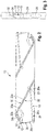
- FIG. 2 the parting lathe tool from FIG. 1 in a side view along direction II
- FIG. 3 the parting lathe tool from FIG. 1 in a frontal view along direction III
- FIG. 4 a variant of the parting lathe tool from FIG. 1 in a broken perspective view
- FIG. 5 a parting lathe tool according to the invention according to a second embodiment in a perspective view
- FIG. 6 the parting lathe tool from FIG. 5 in a side view along direction VI
- FIG. 7 the parting lathe tool from FIG. 5 in a frontal view along direction VII,
- FIG. 8 a parting lathe tool according to the invention in a third embodiment in a perspective view
- FIG. 9 the parting lathe tool from FIG. 8 in a side view along direction IX
- FIG. 10 the parting lathe tool from FIG. 8 in a frontal view along direction X
- FIG. 11 the parting lathe tool from FIG. 8 in a perspective view cut along the plane X-X, and
- FIG. 12 the parting lathe tool from FIG. 8 in a sectional view X-X.
- FIGS. 1 to 3 show a parting lathe tool 10 for machining metal.
- the parting lathe tool 10 can also be referred to as a cutting lathe tool.
- the parting lathe tool 10 comprises a clamping seat 12 to accommodate a cutting insert that is not shown in more detail and which can in particular be an indexable insert. This is basically made up of two clamping faces 14 , 16 between which the cutting insert can be clamped.
- the parting lathe tool 10 also includes an internal coolant supply system 18 for supplying coolant to a cutting zone.
- a coolant supply port 20 is provided on the parting lathe tool 10 on the toolholder side or on the lathe side.
- This is designed as a substantially circular hole and can be fluidly connected to a coolant supply outside the parting lathe tool 10 .
- the parting lathe tool 10 is supplied with coolant via the coolant supply port 20 .
- the coolant supply port 20 is fluidically connected to a first coolant outlet 24 via a first coolant line 22 , to a second coolant outlet 28 via a second coolant line 26 and to a third coolant outlet 32 via a third coolant line 30 .
- the coolant lines 22 , 26 , 30 are fluidically connected to the respectively associated coolant outlets 24 , 28 , 32 .
- the first coolant outlet 24 is provided on the first clamping face 14 .
- the cutting insert can also be supplied solely with coolant via the coolant outlet 24 .
- the second coolant outlet 28 is provided on one end face 34 on the workpiece side of the parting lathe tool 10 .
- the second coolant outlet 28 is located below the clamping seat 12 . This situation is illustrated in FIG. 1 .
- the second coolant outlet 28 is assigned to a free area of the cutting insert, which is not shown, and serves to supply it with a flow of coolant.
- the third coolant outlet 32 is arranged on one workpiece-side end face 36 of a clamping lug 38 of the clamping seat 12 .
- the third coolant outlet 32 will be located above the clamping seat 12 .
- the third coolant outlet 32 is assigned to a cutting face of the cutting insert, which is not shown.
- the cutting face can be supplied with a flow of coolant via the third coolant outlet 32 .
- the coolant line 26 is made of three linear coolant line sections 26 a , 26 b and 26 c . These are substantially circular in cross-section.
- the coolant line sections 26 a , 26 b , 26 c are holes.
- coolant line 22 which is composed of coolant line sections 22 a and 22 b.
- the coolant line 30 comprises coolant line sections 30 a and 30 b which also extend in a straight line and are substantially circular in cross-section.
- the coolant line sections 22 a , 30 a are designed as a single coolant line section which, at a certain distance from the coolant supply port 20 , branches off into the coolant line sections 22 b , 30 b .
- coolant outlets 24 , 32 are supplied with coolant via a common coolant line which is formed by the coolant line section designated 22 a and 30 a.
- Such a parting lathe tool then comprises a total of two coolant lines, namely the coolant line section designated 22 a and 30 a , and the coolant line 26 , and three coolant outlets 24 , 28 , 32 .
- the parting lathe tool 10 shown is designed as a so-called indexable tool. This means that a second clamping seat is provided on the parting lathe tool 10 and is point-symmetrical with respect to the above-described clamping seat 12 . Since the two clamping seats and the associated coolant supply system are identical in design, a separate explanation will be dispensed with.
- parting lathe tool 10 in one variant can also have just one single clamping seat 12 and just one single coolant supply system 18 .
- FIGS. 4 to 6 show a second embodiment of the parting lathe tool 10 .
- the parting lathe tool 10 comprises a first section 10 a produced by means of a generative manufacturing process, and a second section 10 b , also produced by means of a generative manufacturing process.
- the linear coolant line sections 22 a , 22 b of the coolant line 22 are shorter compared with the first embodiment and are connected via a coolant line section 22 c.
- coolant line 26 in which the coolant line segment 26 b is shorter compared with the first embodiment, and the coolant line segment 26 c has been replaced by an arcuate coolant line segment 26 d.
- the coolant line section 26 d is also produced using a generative manufacturing process.
- the coolant line section 30 a and the coolant line section 30 b are connected via an arcuate coolant line section 30 c which is produced using a generative manufacturing process.
- the coolant line sections 22 c , 30 c , 26 d running within the generatively produced sections 10 a , 10 b of the parting lathe tool 10 are produced with a substantially circular cross-section.
- the parting lathe tool can even be produced in its entirety by the generative manufacturing process. In that case, all of the coolant line sections 22 a , 22 b , 22 c , 22 c , 26 a , 26 b , 26 c , 26 c , 26 d , 30 a , 30 b , 30 c are manufactured generatively.
- coolant line sections other than those in the embodiment according to FIGS. 4 to 6 can also be manufactured by means of a generative manufacturing process.
- the coolant line sections 22 a , 30 a and/or the coolant line sections 22 c , 30 c are designed as a single coolant line section which, at a certain distance from the coolant supply port 20 , branches off into the coolant line sections 22 b , 30 b .
- the branch can lie within the region of the coolant line sections 22 a and 30 a or in the region of the coolant line sections 22 c and 30 c .
- the coolant outlets 24 , 32 are supplied with coolant via a common coolant line.
- the parting lathe tool 10 shown is designed as a so-called indexable tool. Again, only one clamping seat 12 and one coolant supply system 18 are described.
- FIGS. 7 to 11 show a third embodiment of the parting lathe tool 10 .
- the course of the coolant lines 22 , 26 , 30 is substantially identical to the second embodiment. However, in the third embodiment, the cross-sections of the coolant lines 22 , 26 , 30 are elliptical in form (see FIGS. 10 and 11 ).
- the parting lathe tool 10 is produced in its entirety by means of a generative manufacturing process. Accordingly even the coolant lines 22 , 26 , 30 are produced in their entirety by a generative manufacturing process.
- the coolant lines 22 , 30 are designed as a single coolant line which at a certain distance from the coolant supply port 20 branches off and is thus fluidically connected to the two coolant outlets 24 , 32 .
- the coolant outlets 24 , 32 are supplied with coolant via a common coolant line.
Abstract
Description
Claims (15)
Applications Claiming Priority (3)
| Application Number | Priority Date | Filing Date | Title |
|---|---|---|---|
| DE102017110132.2 | 2017-05-10 | ||
| DE102017110132 | 2017-05-10 | ||
| DE102017110132.2A DE102017110132A1 (en) | 2017-05-10 | 2017-05-10 | Abstechdrehwerkzeug |
Publications (2)
| Publication Number | Publication Date |
|---|---|
| US20180326500A1 US20180326500A1 (en) | 2018-11-15 |
| US10661352B2 true US10661352B2 (en) | 2020-05-26 |
Family
ID=63962264
Family Applications (1)
| Application Number | Title | Priority Date | Filing Date |
|---|---|---|---|
| US15/971,055 Active US10661352B2 (en) | 2017-05-10 | 2018-05-04 | Parting lathe tool |
Country Status (3)
| Country | Link |
|---|---|
| US (1) | US10661352B2 (en) |
| CN (1) | CN108857566B (en) |
| DE (1) | DE102017110132A1 (en) |
Cited By (2)
| Publication number | Priority date | Publication date | Assignee | Title |
|---|---|---|---|---|
| US20210402485A1 (en) * | 2020-06-30 | 2021-12-30 | Iscar, Ltd. | Indexable parting blade with circuitous coolant channels |
| US11897038B2 (en) * | 2020-09-30 | 2024-02-13 | Iscar, Ltd. | Curved face grooving blade and face grooving holder therefor |
Families Citing this family (7)
| Publication number | Priority date | Publication date | Assignee | Title |
|---|---|---|---|---|
| ES2953461T3 (en) * | 2012-03-06 | 2023-11-13 | Iscar Ltd | Using a knife holder for a chopping knife with high pressure cooling |
| WO2017018369A1 (en) * | 2015-07-24 | 2017-02-02 | 京セラ株式会社 | Cutting tool and method for manufacturing machined workpiece using same |
| US10569337B2 (en) * | 2015-12-25 | 2020-02-25 | Kyocera Corporation | Holder for a cutting tool, cutting tool, and method of manufacturing machined product |
| EP3867001A1 (en) * | 2018-10-17 | 2021-08-25 | Hartmetall-Werkzeugfabrik Paul Horn GmbH | Tool holder and tool having a tool holder of this kind |
| JP7183916B2 (en) * | 2019-03-29 | 2022-12-06 | 三菱マテリアル株式会社 | Head member for grooving tool and grooving tool |
| US10814406B1 (en) | 2019-04-24 | 2020-10-27 | Raytheon Technologies Corporation | Internal cooling passages for rotating cutting tools |
| DE102019116864A1 (en) * | 2019-06-24 | 2020-12-24 | Zcc Cutting Tools Europe Gmbh | Clamp holder |
Citations (8)
| Publication number | Priority date | Publication date | Assignee | Title |
|---|---|---|---|---|
| US5718156A (en) * | 1993-12-01 | 1998-02-17 | Societe Nationale D'etude Et De Construction De Monteurs D'aviation "Snecma" | Process for machining titanium parts using separate biased spraying collar |
| US5901623A (en) * | 1994-08-09 | 1999-05-11 | The Edison Materials Technology Center | Cryogenic machining |
| US20020127067A1 (en) * | 1999-09-02 | 2002-09-12 | Stig Lagerberg | Machine for chip cutting machining plus cutting tool for such machines |
| US20130129428A1 (en) * | 2011-11-22 | 2013-05-23 | Kennametal Inc. | Cutting assembly with enhanced coolant delivery |
| US20140030033A1 (en) * | 2011-03-28 | 2014-01-30 | Ernst Graf Gmbh | Tool for the machining of a workpiece with lateral coolant outlet |
| US20150352640A1 (en) * | 2014-06-05 | 2015-12-10 | Kennametal Inc. | Tool holder having improved internal coolant delivery |
| US20160175938A1 (en) * | 2014-12-19 | 2016-06-23 | Kennametal Inc. | Tool holder for a cutting insert and process for manufacturing the tool holder |
| US20160339523A1 (en) * | 2014-01-27 | 2016-11-24 | Rosswag Gmbh | Cut-Off Tool Holder and Production Method |
Family Cites Families (4)
| Publication number | Priority date | Publication date | Assignee | Title |
|---|---|---|---|---|
| DE50006020D1 (en) * | 1999-12-31 | 2004-05-13 | Volkmar Mauel | Cutting tool with a device for indirect cooling of an insert. |
| CN201140280Y (en) * | 2008-01-10 | 2008-10-29 | 四川天虎工具有限责任公司 | Indexable mechanically-clamped strong air cooling double-end heavy type lathe cutter |
| DE102012111576B4 (en) * | 2012-11-29 | 2022-05-25 | Kennametal Inc. | Cutting insert with coolant channel and cutting tool with a tool holder and such a cutting insert |
| EP2873477A3 (en) * | 2013-11-14 | 2015-12-23 | Sandvik Tooling France | Cartridge for a grooving tool holder, corresponding grooving tool holder, kit and assembly thereof |
-
2017
- 2017-05-10 DE DE102017110132.2A patent/DE102017110132A1/en active Pending
-
2018
- 2018-04-26 CN CN201810383862.5A patent/CN108857566B/en active Active
- 2018-05-04 US US15/971,055 patent/US10661352B2/en active Active
Patent Citations (8)
| Publication number | Priority date | Publication date | Assignee | Title |
|---|---|---|---|---|
| US5718156A (en) * | 1993-12-01 | 1998-02-17 | Societe Nationale D'etude Et De Construction De Monteurs D'aviation "Snecma" | Process for machining titanium parts using separate biased spraying collar |
| US5901623A (en) * | 1994-08-09 | 1999-05-11 | The Edison Materials Technology Center | Cryogenic machining |
| US20020127067A1 (en) * | 1999-09-02 | 2002-09-12 | Stig Lagerberg | Machine for chip cutting machining plus cutting tool for such machines |
| US20140030033A1 (en) * | 2011-03-28 | 2014-01-30 | Ernst Graf Gmbh | Tool for the machining of a workpiece with lateral coolant outlet |
| US20130129428A1 (en) * | 2011-11-22 | 2013-05-23 | Kennametal Inc. | Cutting assembly with enhanced coolant delivery |
| US20160339523A1 (en) * | 2014-01-27 | 2016-11-24 | Rosswag Gmbh | Cut-Off Tool Holder and Production Method |
| US20150352640A1 (en) * | 2014-06-05 | 2015-12-10 | Kennametal Inc. | Tool holder having improved internal coolant delivery |
| US20160175938A1 (en) * | 2014-12-19 | 2016-06-23 | Kennametal Inc. | Tool holder for a cutting insert and process for manufacturing the tool holder |
Cited By (4)
| Publication number | Priority date | Publication date | Assignee | Title |
|---|---|---|---|---|
| US20210402485A1 (en) * | 2020-06-30 | 2021-12-30 | Iscar, Ltd. | Indexable parting blade with circuitous coolant channels |
| WO2022003671A1 (en) | 2020-06-30 | 2022-01-06 | Iscar Ltd. | Indexable parting blade with circuitous coolant channels |
| US11565327B2 (en) * | 2020-06-30 | 2023-01-31 | Iscar, Ltd. | Indexable parting blade with circuitous coolant channels |
| US11897038B2 (en) * | 2020-09-30 | 2024-02-13 | Iscar, Ltd. | Curved face grooving blade and face grooving holder therefor |
Also Published As
| Publication number | Publication date |
|---|---|
| DE102017110132A1 (en) | 2018-11-15 |
| US20180326500A1 (en) | 2018-11-15 |
| CN108857566B (en) | 2022-06-03 |
| CN108857566A (en) | 2018-11-23 |
Similar Documents
| Publication | Publication Date | Title |
|---|---|---|
| US10661352B2 (en) | Parting lathe tool | |
| EP2946857B1 (en) | Turning tool holder and cutting tool insert | |
| EP3248721B1 (en) | Tool comprising a tool holder | |
| US9931699B2 (en) | Cutting tool holder and cutting tool | |
| EP2313224B1 (en) | Milling cutter and cutting insert therefor | |
| US20150063926A1 (en) | Indexable cutting insert with coolant delivery | |
| US9827614B2 (en) | Cutting tool assembly having clamp assembly comprising a clamp and a coolant plate | |
| US20150063931A1 (en) | Indexable drill assembly and drill body having coolant supply | |
| US20200001383A1 (en) | Metal-cutting tool, in particular a reaming tool and method of making the same | |
| US20130115017A1 (en) | Chip breaker system, cooling channel, cooling channel system and high-speed reamer comprising at least one thereof | |
| WO2018047158A1 (en) | Cutting tool having a coolant chamber with an integrally formed coolant deflection portion and tool body | |
| KR20160013797A (en) | Blade positioning structure of disposable milling cutter | |
| US11141795B2 (en) | Cutting tool and method for manufacturing a cutting tool | |
| KR20130038292A (en) | Cutting insert and indexable rotary cutting tool | |
| WO2017110903A1 (en) | Cutting tool holder, cutting tool, and method for manufacturing cut workpiece | |
| EP3150319B1 (en) | A tool body, a milling tool and a method for manufacturing a tool body | |
| US11491594B2 (en) | Tooling assembly with internal coolant passages for machines | |
| JP2010094766A (en) | Boring tool | |
| CN113458463B (en) | Composite multi-edge PCD reamer for machining automobile engine cylinder body hole | |
| US10875099B2 (en) | Turning tool holder and turning tool | |
| WO2020162581A1 (en) | Cutting insert and cutting tool | |
| JP7312387B1 (en) | Indexable cutting tools and cutting inserts | |
| JP7449504B1 (en) | Cutting tool and its body | |
| US20230024391A1 (en) | Shank and cutting tool having the shank | |
| CN113458472A (en) | Multi-step multi-profile coating forming reaming milling cutter |
Legal Events
| Date | Code | Title | Description |
|---|---|---|---|
| FEPP | Fee payment procedure |
Free format text: ENTITY STATUS SET TO UNDISCOUNTED (ORIGINAL EVENT CODE: BIG.); ENTITY STATUS OF PATENT OWNER: LARGE ENTITY |
|
| AS | Assignment |
Owner name: KENNAMETAL INC., PENNSYLVANIA Free format text: ASSIGNMENT OF ASSIGNORS INTEREST;ASSIGNORS:KAUFMANN, IGOR;BIRKMANN, FABIAN;SIGNING DATES FROM 20180704 TO 20180706;REEL/FRAME:046306/0535 |
|
| STPP | Information on status: patent application and granting procedure in general |
Free format text: DOCKETED NEW CASE - READY FOR EXAMINATION |
|
| STPP | Information on status: patent application and granting procedure in general |
Free format text: NON FINAL ACTION MAILED |
|
| STPP | Information on status: patent application and granting procedure in general |
Free format text: RESPONSE TO NON-FINAL OFFICE ACTION ENTERED AND FORWARDED TO EXAMINER |
|
| STPP | Information on status: patent application and granting procedure in general |
Free format text: FINAL REJECTION MAILED |
|
| STPP | Information on status: patent application and granting procedure in general |
Free format text: NON FINAL ACTION MAILED |
|
| STPP | Information on status: patent application and granting procedure in general |
Free format text: RESPONSE TO NON-FINAL OFFICE ACTION ENTERED AND FORWARDED TO EXAMINER |
|
| STPP | Information on status: patent application and granting procedure in general |
Free format text: NOTICE OF ALLOWANCE MAILED -- APPLICATION RECEIVED IN OFFICE OF PUBLICATIONS |
|
| STPP | Information on status: patent application and granting procedure in general |
Free format text: PUBLICATIONS -- ISSUE FEE PAYMENT RECEIVED |
|
| STCF | Information on status: patent grant |
Free format text: PATENTED CASE |
|
| MAFP | Maintenance fee payment |
Free format text: PAYMENT OF MAINTENANCE FEE, 4TH YEAR, LARGE ENTITY (ORIGINAL EVENT CODE: M1551); ENTITY STATUS OF PATENT OWNER: LARGE ENTITY Year of fee payment: 4 |