WO2020162581A1 - Cutting insert and cutting tool - Google Patents
Cutting insert and cutting tool Download PDFInfo
- Publication number
- WO2020162581A1 WO2020162581A1 PCT/JP2020/004701 JP2020004701W WO2020162581A1 WO 2020162581 A1 WO2020162581 A1 WO 2020162581A1 JP 2020004701 W JP2020004701 W JP 2020004701W WO 2020162581 A1 WO2020162581 A1 WO 2020162581A1
- Authority
- WO
- WIPO (PCT)
- Prior art keywords
- cutting
- rake face
- cooling
- cutting insert
- internal cooling
- Prior art date
Links
Images


Classifications
-
- B—PERFORMING OPERATIONS; TRANSPORTING
- B23—MACHINE TOOLS; METAL-WORKING NOT OTHERWISE PROVIDED FOR
- B23B—TURNING; BORING
- B23B27/00—Tools for turning or boring machines; Tools of a similar kind in general; Accessories therefor
- B23B27/10—Cutting tools with special provision for cooling
-
- B—PERFORMING OPERATIONS; TRANSPORTING
- B23—MACHINE TOOLS; METAL-WORKING NOT OTHERWISE PROVIDED FOR
- B23B—TURNING; BORING
- B23B27/00—Tools for turning or boring machines; Tools of a similar kind in general; Accessories therefor
- B23B27/14—Cutting tools of which the bits or tips or cutting inserts are of special material
- B23B27/148—Composition of the cutting inserts
-
- B—PERFORMING OPERATIONS; TRANSPORTING
- B23—MACHINE TOOLS; METAL-WORKING NOT OTHERWISE PROVIDED FOR
- B23B—TURNING; BORING
- B23B27/00—Tools for turning or boring machines; Tools of a similar kind in general; Accessories therefor
- B23B27/14—Cutting tools of which the bits or tips or cutting inserts are of special material
- B23B27/16—Cutting tools of which the bits or tips or cutting inserts are of special material with exchangeable cutting bits or cutting inserts, e.g. able to be clamped
- B23B27/1625—Cutting tools of which the bits or tips or cutting inserts are of special material with exchangeable cutting bits or cutting inserts, e.g. able to be clamped with plate-like cutting inserts of special shape clamped by a clamping member acting almost perpendicularly on the chip-forming plane
- B23B27/164—Cutting tools of which the bits or tips or cutting inserts are of special material with exchangeable cutting bits or cutting inserts, e.g. able to be clamped with plate-like cutting inserts of special shape clamped by a clamping member acting almost perpendicularly on the chip-forming plane characterised by having a special shape
-
- B—PERFORMING OPERATIONS; TRANSPORTING
- B23—MACHINE TOOLS; METAL-WORKING NOT OTHERWISE PROVIDED FOR
- B23B—TURNING; BORING
- B23B2205/00—Fixation of cutting inserts in holders
- B23B2205/16—Shims
Definitions
- the present disclosure relates to cutting inserts and cutting tools.
- This application is based on Japanese Patent Application No. 2019-021386 filed on February 8, 2019, and claims the benefit of its priority, and the entire contents of the patent application are Incorporated herein by reference.
- Non-Patent Document 1 discloses a cooling cutting device provided with a circulation circuit of a cooling liquid which is provided with a through hole in a shank to which a tool blade edge is attached and which returns from a cooling tank to a cooling tank through a through hole of the shank.
- Non-Patent Document 1 discloses a structure in which a tool edge is cooled through a cooled shank, but the rake face in the vicinity of the edge, which has the highest temperature, is separated from the shank through hole through which the cooling liquid passes, so cooling is performed. Not very efficient.
- the present disclosure has been made in view of such circumstances, and is to provide a structure for cooling the rake face near the cutting edge.
- a cutting insert has a rake face, a cutting edge formed on the outer periphery of the rake face, a base portion supporting the rake face, and a fluid for cooling the rake face.
- An internal cooling passage is provided.
- a cutting tool includes a tool body, a cutting insert having an internal cooling passage, and a supply port for supplying a fluid to the internal cooling passage.
- FIG. 1 It is a figure which shows a temperature distribution analysis result. It is a figure which shows schematic structure of the cutting tool which concerns on embodiment. It is an enlarged view of around the cutting edge. It is a figure which shows the cross section of a cutting tool. It is a figure which shows the structure of a base body. It is a figure which shows the structure of a thin plate member. It is a figure which shows the modification of the cross section of a cutting tool. It is a figure which shows the upper surface of a base body.
- FIG. 1(a) shows a temperature distribution analysis result when a tool is cutting a workpiece
- FIG. 1(b) is an enlarged temperature distribution analysis result near the cutting edge. Is.
- the chips contact the rake face near the cutting edge immediately after cutting. It is observed that frictional heat and shear insulation are transferred from the chips to the rake face near the cutting edge, and the temperature becomes higher than that of the cutting edge. In this analysis, the maximum temperature of the rake face rose to nearly 1000 degrees. Temperatures near 1000 degrees may cause thermal wear, even with cemented carbide inserts with high high temperature strength.
- the temperature drops to near 200 degrees. .. This is because the distance from the contact point between the chip and the rake face is sufficiently large, and it is clear from the analysis that the place to be cooled must be near the contact point.
- the cutting thickness is about several tens of ⁇ m (microns) to about 300 microns under many practical cutting conditions, the portion to be cooled needs to be within 1.5 mm from the cutting edge.
- the contact length between the rake face and the chips correlates with the cutting thickness of the work material. Strictly speaking, this correlation also depends on the cutting speed, the shape of the cutting edge of the tool, etc., but when the practical conditions are adopted, the contact length between the rake face and the chips is the same as the cutting thickness shown in Fig. 1. Less than several times In consideration of the fact that the cutting thickness is about several tens of microns to about three hundreds of microns under many practical cutting conditions, the contact length is within the range of 1.5 mm. The embodiments of the present disclosure will be described below based on these considerations.
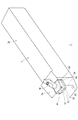
- FIG. 2 shows a schematic configuration of the cutting tool according to the embodiment.
- the cutting tool 1 includes a shank 2 formed of steel material.
- the shank 2 is a tool body, and has a shank tip portion 2a on which the cutting insert 10 is mounted and a held portion 2b held by a machine tool during cutting.
- the upper surface of the shank tip portion 2a is formed higher than the upper surface of the held portion 2b, and a cutout portion for mounting the cutting insert 10 and the sheet member 12 is provided in a part of the upper surface tip side of the shank tip portion 2a.
- the cutting insert 10 and the sheet member 12 are made of a hard material such as cemented carbide, are arranged in the notch, and are fixed to the shank 2 by the clamp member 14.
- the cutting insert 10 and the sheet member 12 may be fixed to the shank 2 by other means.
- a screw hole penetrating the cutting insert 10 and the sheet member 12 may be provided, and the cutting insert 10 and the sheet member 12 may be directly fixed to the shank 2 by a screw member. ..
- the cutting insert 10 may be directly fixed to the cutout portion of the shank tip portion 2a without the sheet member 12.
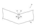
- FIG. 3 is an enlarged view of the periphery of the cutting edge of the cutting insert 10.
- the cutting insert 10 includes a rake face 22, a cutting edge 20 formed on the outer periphery of the rake face 22, and a base portion 24 that supports the rake face 22.
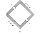
- the cutting insert 10 of the embodiment includes two cutting edges 20 located on the diagonal line of the rake face 22, but may include the cutting edges 20 at each corner.
- the base portion 24, the sheet member 12 and the shank tip portion 2a are provided with an internal cooling passage 40 through which a fluid for cooling the rake face 22 flows.
- the cooling fluid supplied to the internal cooling passage 40 may be a liquid such as a water-soluble cutting fluid or a water-insoluble cutting fluid, but may be a gas such as cooling air.
- the supply port 32 which is an inlet of the internal cooling passage 40 is formed on the lower surface of the shank tip portion 2a, and the outlet of the internal cooling passage 40 is formed on the flank near the cutting edge 20 of the base 24 of the cutting insert 10.
- a plurality of flow passage openings 30a, 30b, 30c (hereinafter, may be referred to as "flow passage opening 30" unless otherwise specified) are formed.
- the internal cooling passage 40 passes through the inside of the shank tip portion 2 a from the supply port 32, penetrates the sheet member 12, and extends directly below the rake face 22, and the rake face 22 on the rear surface side of the rake face 22.
- the cooling channel extends parallel to the channel opening 30.
- the term “parallel to the rake face 22” may include a configuration that is substantially parallel to the rake face 22 without departing from the intended purpose.
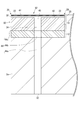
- FIG. 4 shows a cross section of the cutting tool 1 taken along a diagonal line of a rake face 22 provided with a pair of cutting edges 20. Illustration of the clamp member 14 is omitted.
- the internal cooling passage 40 has an introduction flow passage 44 extending from the supply port 32 to just below the rake face 22, and a cooling flow passage 42 extending from the end of the introduction flow passage 44 to the flow passage opening 30 parallel to the rake face 22. Have.
- the introduction flow path 44 includes a first introduction flow path 44a formed in the shank tip 2a, a second introduction flow path 44b formed in the sheet member 12, and a third introduction flow path formed in the base portion 24 of the cutting insert 10. It has a channel 44c.
- the introduction flow passage 44 shown in FIG. 4 is formed in a straight line perpendicular to the lower surface of the shank tip portion 2a, but the first introduction flow passage 44a is bent so that the supply port 32 has the shank tip portion 2a. It may be provided on the side surface.
- the supply port 32 is preferably provided at a position where it is easy to supply the cooling fluid by the machine tool. The butt surfaces of each member may be sealed to prevent leakage of the cooling fluid.
- the cooling channel 42 is formed as a groove-shaped channel parallel to the rake face 22.
- the cooling flow path 42 is provided at least on the back surface side of the region where the chips of the work material come into contact with the rake face 22.
- the cooling flow path 42 causes the cooling fluid supplied from the supply port 32 through the introduction flow path 44 to flow toward the flow path opening 30 formed immediately below the cutting edge 20 along the rake face 22, It also has a role of cooling the rake face 22 near the cutting edge 20.
- the cutting insert 10 of the embodiment includes a thin plate member 52 having a rake face 22 on the upper surface thereof, and a base body 50 that constitutes the base 24 that supports the thin plate member 52, and an upper surface of the base body 50 has a lower surface of the thin plate member 52 (
- the cooling channels 42 are formed by combining the back surfaces.
- FIG. 5A shows the upper surface of the base body 50
- FIG. 5B shows a partial cross section of the upper surface.
- a plurality of cooling channels 42a, 42b, 42c (hereinafter, referred to as "cooling channels 42" unless otherwise specified) for flowing a cooling fluid are provided in parallel with each other.
- the cooling flow passage 42 is provided at least over a section connecting the position of the cutting edge 20 on the rake face 22 and the region where the chips contact the rake face 22. As described above, under practical conditions, the contact length between the chips and the rake face 22 falls within the range of 1.5 mm from the cutting edge.
- the cooling flow path 42 may be provided in a section about 1.5 mm from the position of the cutting edge of the cutting edge 20.
- the cooling flow passage 42 of the embodiment is formed so as to extend from the upper end of the third introduction flow passage 44c toward the corner portion corresponding to the position of the cutting edge 20 on the rake face 22.
- FIG. 6A shows the upper surface of the thin plate member 52
- FIG. 6B shows the lower surface of the thin plate member 52
- the upper surface of the thin plate member 52 is a rake surface 22, and a plurality of cutting edges 20 are formed on the outer circumference.
- the lower surface of the thin plate member 52 is arranged to match the upper surface of the base body 50, and the cooling flow path 42 is provided between the base body 50 and the lower surface of the thin plate member 52.
- the cooling flow passage 42 is provided within a depth of 1.5 mm from the rake face 22.
- the depth of the cooling flow passage 42 from the rake face 22 is defined by the distance between the upper surface of the cooling flow passage 42 and the rake face 22, and is therefore equal to the thickness of the thin plate member 52.
- the depth from the rake face 22 of the cooling flow path 42 that is, the thickness of the thin plate member 52 is 0.2 mm or more and 1.5 mm.
- the range is preferably set to the following, more preferably 0.2 mm or more and 1 mm or less, and further preferably 0.2 mm or more and 0.5 mm or less.
- the thin plate member 52 is formed of a cemented carbide having low toughness, if the width Wa of the cooling flow passage 42 is wider than the above depth, the thin plate member 52 may crack. Therefore, the flow passage width Wa is designed to be equal to or less than a predetermined length, and specifically, it is preferable to be equal to or less than the depth. Further, in order to avoid cracking of the thin plate member 52, it is preferable that the ratio (Wa/Wb) of the flow passage width Wa and the flow passage length Wb is set to 1 or less.
- the cutting insert 10 By forming the cutting insert 10 with two members, the base body 50 and the thin plate member 52, manufacturing becomes easy. Further, when the channel opening 30 is clogged with chips during use, the chips can be easily removed by removing the thin plate member 52 from the base body 50. Further, when the cutting edge 20 is worn, it is only necessary to replace the thin plate member 52 and there is an advantage that the base body 50 can be reused.
- the cooling flow path 42 is formed on the upper surface of the base body 50, but the cooling flow path 42 may be formed on the lower surface of the thin plate member 52, and may be formed on both the upper surface of the base body 50 and the lower surface of the thin plate member 52.
- the cooling channel 42 may be formed.
- the introduction flow path 44 is also formed in the sheet member 12 and the shank tip portion 2a, but the third introduction flow path 44c is not formed, and cooling is performed from the flow path opening 30 on the other cutting edge 20 side. It is also possible to supply a fluid.
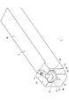
- FIG. 7 shows a schematic configuration of a cutting tool according to a modification.
- FIG. 8 shows the upper surface of the base body 50 in the modified example.
- the cooling structure shown in FIG. 4 discharges the cooling fluid from the flow path opening 30 just below the cutting edge 20, but the cooling structure shown in FIG. 7 corresponds to the dry machining, and the flow provided on the lower surface of the shank tip portion 2a.
- the cooling fluid is discharged from the passage opening 30.
- the internal cooling passage has an introduction flow passage 44 extending from the supply port 32 to just below the rake face 22, and cooling passages 48d, 48e, 48f extending in parallel to the rake face 22 from the end of the introduction flow passage 44, It has 48 g, 48 h, 48 i (hereinafter, referred to as “cooling channel 48 ”), and a discharge channel 46 extending from immediately below the rake face 22 to the channel opening 30.
- cooling channel 48 the supply port 32 serving as the inlet of the internal cooling passage 40 and the flow passage opening 30 serving as the outlet of the internal cooling passage 40 are formed on the lower surface of the shank tip 2a.
- the cooling flow channel 48 is formed as a groove-shaped flow channel parallel to the rake face 22, and is provided at least on the back surface side of the region where the chips of the work material come into contact with the rake face 22.
- the cooling flow path 48 directs the cooling fluid supplied from the supply port 32 through the introduction flow path 44 toward the discharge flow path 46 so as to pass through the region near the cutting edge 20 along the rake face 22. It has a role of flowing and cooling the rake face 22 near the cutting edge 20.
- the cutting edge 20 may be formed at the four corners of the rake face 22.
- the plurality of cooling flow paths 48 provided in parallel are 1.5 mm apart from the cutting edge position of the cutting edge 20. It is preferably provided so as to cover the range.
- the cutting insert 10 is formed of two members, the base body 50 and the thin plate member 52, but may be formed as an integral structure.
- the cutting insert 10 when manufacturing a cutting insert by sintering, after compression molding a cemented carbide powder in which a low melting point material having a shape to be an internal cooling path is embedded, and then firing at high temperature, the low melting point material is eluted,
- the internal cooling passage may be configured.
- the shank 2 is shown as the tool body of the cutting tool 1, but the cutting tool 1 is not limited to a turning tool, and may be a milling tool having a cutter body.
- a cutting insert according to an aspect of the present disclosure includes a rake face, a cutting edge formed on the outer periphery of the rake face, a base portion that supports the rake face, and an internal cooling passage through which a fluid that cools the rake face flows.
- the cutting insert can be efficiently cooled.
- the internal cooling passage may be provided on the back surface side of the region where the chips of the work material come into contact with the rake face. By providing the internal cooling passage on the back surface side of the contact area, the cooling efficiency can be improved. At least a part of the internal cooling passage may be provided on the back surface side of the region so as to extend parallel to the rake face.
- the internal cooling passage is provided within a depth of 1.5 mm from the rake face. Cooling efficiency can be improved by providing the internal cooling passage at a depth of 1.5 mm or less from the rake face.
- the cutting insert may include a thin plate member whose upper surface is a rake surface, and an internal cooling passage may be provided between the base portion and the lower surface of the thin plate member.
- a cutting tool may include a tool body such as a shank, a cutting insert having an internal cooling passage, and a supply port for supplying a fluid to the internal cooling passage.
Abstract
Provided is a structure that cools a cutting surface near a cutting edge. A cutting insert (10) comprises: a cutting surface (22); a cutting blade (20) that is formed on the outer periphery of the cutting surface (22); a base part (24) that supports the cutting surface (22); and an internal cooling path (40) through which fluid configured to cool the cutting surface (22) flows. The internal cooling path (40) has an introduction flow path (44) and a cooling flow path (42), wherein the cooling flow path (42) is provided on a rear surface side of a region where a cutting layer of an object to be cut is in contact with the cutting surface (22). The cooling flow path (42) is provided at a depth of 1.5 mm from the cutting surface (22).
Description
本開示は、切削インサートおよび切削工具に関する。本出願は、2019年2月8日に出願された日本国特許出願2019-021386号に基づくものであって、その優先権の利益を主張するものであり、その特許出願の全ての内容が、参照により本明細書に組み込まれる。
The present disclosure relates to cutting inserts and cutting tools. This application is based on Japanese Patent Application No. 2019-021386 filed on February 8, 2019, and claims the benefit of its priority, and the entire contents of the patent application are Incorporated herein by reference.
切削時に発生する摩擦熱や剪断熱が工具刃先温度を上昇させ、熱的摩耗を生じさせることが知られている。切削加工中、発生する摩擦熱や剪断熱を吸収する目的で切削油剤が工具刃先に供給されるが、最も高温となる刃先近傍の工具すくい面は切屑に接触しているため切削油剤が到達せず、接触箇所の温度を十分に下げることは容易でない。
It is known that frictional heat and shearing heat generated during cutting raise the temperature of the tool edge and cause thermal wear. During cutting, cutting oil is supplied to the cutting edge of the tool in order to absorb the frictional heat and shearing heat generated, but the cutting tool reaches the highest temperature because the rake face near the cutting edge is in contact with chips. Therefore, it is not easy to sufficiently lower the temperature at the contact point.
非特許文献1は、工具刃先を装着するシャンクに貫通穴をあけ、冷却槽からシャンクの貫通穴を通って冷却槽に戻る冷却液の循環回路を備えた冷却切削装置を開示する。
Non-Patent Document 1 discloses a cooling cutting device provided with a circulation circuit of a cooling liquid which is provided with a through hole in a shank to which a tool blade edge is attached and which returns from a cooling tank to a cooling tank through a through hole of the shank.
非特許文献1は、冷却されたシャンクを介して工具刃先を冷却する構造を開示するが、最も高温となる刃先近傍のすくい面は、冷却液が通過するシャンク貫通穴から離れているため、冷却効率が高いとはいえない。
Non-Patent Document 1 discloses a structure in which a tool edge is cooled through a cooled shank, but the rake face in the vicinity of the edge, which has the highest temperature, is separated from the shank through hole through which the cooling liquid passes, so cooling is performed. Not very efficient.
本開示はこうした状況に鑑みてなされており、刃先近傍のすくい面を冷却する構造を提供することにある。
The present disclosure has been made in view of such circumstances, and is to provide a structure for cooling the rake face near the cutting edge.
上記課題を解決するために、本発明のある態様の切削インサートは、すくい面と、すくい面の外周に形成される切れ刃と、すくい面を支持する基部と、すくい面を冷却する流体を流す内部冷却路と、を備える。
In order to solve the above problems, a cutting insert according to an aspect of the present invention has a rake face, a cutting edge formed on the outer periphery of the rake face, a base portion supporting the rake face, and a fluid for cooling the rake face. An internal cooling passage.
本発明の別の態様の切削工具は、工具本体と、内部冷却路を備えた切削インサートと、内部冷却路に流体を供給するための供給口と、を備える。
A cutting tool according to another aspect of the present invention includes a tool body, a cutting insert having an internal cooling passage, and a supply port for supplying a fluid to the internal cooling passage.
本開示によれば、刃先近傍のすくい面を冷却する構造を提供できる。
According to the present disclosure, it is possible to provide a structure for cooling the rake face near the cutting edge.
本開示の実施形態を説明する前に、刃先近傍のすくい面の温度上昇について説明する。
図1(a)は、工具(tool)が被削材(workpiece)を切削しているときの温度分布解析結果を示し、図1(b)は、刃先近傍の温度分布解析結果を拡大したものである。 Before describing the embodiments of the present disclosure, the temperature increase of the rake face near the cutting edge will be described.
FIG. 1(a) shows a temperature distribution analysis result when a tool is cutting a workpiece, and FIG. 1(b) is an enlarged temperature distribution analysis result near the cutting edge. Is.
図1(a)に示すように、切屑(chip)は、切削直後に刃先近傍のすくい面と接触する。刃先近傍のすくい面には切屑から摩擦熱および剪断熱が伝達され、刃先より高温となることが観察される。この解析では、すくい面の最高温度が1000度近くまで上昇した。1000度近傍の温度は、高温強度が高い超硬合金製インサートであっても、熱的摩耗を生じさせる可能性がある。
As shown in Fig. 1(a), the chips contact the rake face near the cutting edge immediately after cutting. It is observed that frictional heat and shear insulation are transferred from the chips to the rake face near the cutting edge, and the temperature becomes higher than that of the cutting edge. In this analysis, the maximum temperature of the rake face rose to nearly 1000 degrees. Temperatures near 1000 degrees may cause thermal wear, even with cemented carbide inserts with high high temperature strength.
この解析によると、約1000度の最高温度に対して、刃先から被削材の切取り厚さ(2次元切削における切込み量)の5倍程度離れた位置では、200度近くの温度まで下がっている。これは切屑とすくい面との接触箇所から十分に離れているためであり、したがって冷却するべき箇所が、接触箇所の近傍でなければならないことが解析から明らかである。実用的な多くの切削条件において切取り厚さが数十μm(ミクロン)から三百ミクロン程度までであることを考慮すると、冷却するべき箇所は刃先から1.5mm以内である必要がある。
According to this analysis, at a position about 5 times the cutting thickness (cut amount in two-dimensional cutting) of the work material from the cutting edge with respect to the maximum temperature of about 1000 degrees, the temperature drops to near 200 degrees. .. This is because the distance from the contact point between the chip and the rake face is sufficiently large, and it is clear from the analysis that the place to be cooled must be near the contact point. Considering that the cutting thickness is about several tens of μm (microns) to about 300 microns under many practical cutting conditions, the portion to be cooled needs to be within 1.5 mm from the cutting edge.
また、すくい面と切屑との接触長さは、被削材の切取り厚さと相関があることが知られている。この相関関係は厳密には切削速度、工具刃先形状等にも依存するが、実用的な条件を採用した場合、すくい面と切屑との接触長さは、図1に示す例のように切取り厚さの数倍以下となる。実用的な多くの切削条件において、切取り厚さが数十ミクロンから三百ミクロン程度までであることを考慮すると、接触長さも1.5mmの範囲内に収まる。以下、これらの考察をふまえて、本開示の実施形態を説明する。
Also, it is known that the contact length between the rake face and the chips correlates with the cutting thickness of the work material. Strictly speaking, this correlation also depends on the cutting speed, the shape of the cutting edge of the tool, etc., but when the practical conditions are adopted, the contact length between the rake face and the chips is the same as the cutting thickness shown in Fig. 1. Less than several times In consideration of the fact that the cutting thickness is about several tens of microns to about three hundreds of microns under many practical cutting conditions, the contact length is within the range of 1.5 mm. The embodiments of the present disclosure will be described below based on these considerations.
図2は、実施形態に係る切削工具の概略構成を示す。切削工具1は、鋼材により形成されるシャンク2を備える。シャンク2は工具本体であって、切削インサート10を装着するシャンク先端部2aと、切削加工時に工作機械によって保持される被保持部2bとを有する。シャンク先端部2aの上面は、被保持部2bの上面より一段高く形成され、シャンク先端部2aの上面先端側の一部に、切削インサート10およびシート部材12を装着するための切り欠き部が設けられる。
FIG. 2 shows a schematic configuration of the cutting tool according to the embodiment. The cutting tool 1 includes a shank 2 formed of steel material. The shank 2 is a tool body, and has a shank tip portion 2a on which the cutting insert 10 is mounted and a held portion 2b held by a machine tool during cutting. The upper surface of the shank tip portion 2a is formed higher than the upper surface of the held portion 2b, and a cutout portion for mounting the cutting insert 10 and the sheet member 12 is provided in a part of the upper surface tip side of the shank tip portion 2a. To be
切削インサート10およびシート部材12は超硬合金等の硬質材料から形成され、切り欠き部に配置されて、クランプ部材14によりシャンク2に固定される。なお切削インサート10およびシート部材12は他の手段によってシャンク2に固定されてよく、たとえば切削インサート10およびシート部材12を貫通するねじ穴が設けられ、ねじ部材によりシャンク2に直接固定されてもよい。なお切削インサート10がシート部材12を介さず、シャンク先端部2aの切り欠き部に直接固定されてもよい。
The cutting insert 10 and the sheet member 12 are made of a hard material such as cemented carbide, are arranged in the notch, and are fixed to the shank 2 by the clamp member 14. The cutting insert 10 and the sheet member 12 may be fixed to the shank 2 by other means. For example, a screw hole penetrating the cutting insert 10 and the sheet member 12 may be provided, and the cutting insert 10 and the sheet member 12 may be directly fixed to the shank 2 by a screw member. .. The cutting insert 10 may be directly fixed to the cutout portion of the shank tip portion 2a without the sheet member 12.
図3は、切削インサート10の切れ刃周辺を拡大した図である。切削インサート10は、すくい面22と、すくい面22の外周に形成される切れ刃20と、すくい面22を支持する基部24とを備える。実施形態の切削インサート10は、すくい面22の対角線上に位置する2つの切れ刃20を備えるが、各角部に切れ刃20を備えてもよい。
FIG. 3 is an enlarged view of the periphery of the cutting edge of the cutting insert 10. The cutting insert 10 includes a rake face 22, a cutting edge 20 formed on the outer periphery of the rake face 22, and a base portion 24 that supports the rake face 22. The cutting insert 10 of the embodiment includes two cutting edges 20 located on the diagonal line of the rake face 22, but may include the cutting edges 20 at each corner.
基部24、シート部材12およびシャンク先端部2aには、すくい面22を冷却する流体を流す内部冷却路40が設けられる。内部冷却路40に供給される冷却用流体は、たとえば水溶性切削油剤や不水溶性切削油剤などの液体であってよいが、冷却空気などの気体であってもよい。切削工具1では、シャンク先端部2aの下面に、内部冷却路40の入口となる供給口32が形成され、切削インサート10の基部24の切れ刃20近傍の逃げ面に、内部冷却路40の出口となる複数の流路開口30a、30b、30c(以下、特に区別しない場合には「流路開口30」と呼ぶこともある)が形成される。内部冷却路40は、供給口32からシャンク先端部2aの内部を通り、シート部材12を貫通して、すくい面22の直下まで延びる導入流路と、すくい面22の裏面側にてすくい面22に平行に流路開口30まで延在する冷却流路を有する。実施形態において、すくい面22に平行とは、所期の目的を逸脱しない範囲で実質的に平行な形態を含んでよい。
The base portion 24, the sheet member 12 and the shank tip portion 2a are provided with an internal cooling passage 40 through which a fluid for cooling the rake face 22 flows. The cooling fluid supplied to the internal cooling passage 40 may be a liquid such as a water-soluble cutting fluid or a water-insoluble cutting fluid, but may be a gas such as cooling air. In the cutting tool 1, the supply port 32 which is an inlet of the internal cooling passage 40 is formed on the lower surface of the shank tip portion 2a, and the outlet of the internal cooling passage 40 is formed on the flank near the cutting edge 20 of the base 24 of the cutting insert 10. A plurality of flow passage openings 30a, 30b, 30c (hereinafter, may be referred to as "flow passage opening 30" unless otherwise specified) are formed. The internal cooling passage 40 passes through the inside of the shank tip portion 2 a from the supply port 32, penetrates the sheet member 12, and extends directly below the rake face 22, and the rake face 22 on the rear surface side of the rake face 22. The cooling channel extends parallel to the channel opening 30. In the embodiment, the term “parallel to the rake face 22” may include a configuration that is substantially parallel to the rake face 22 without departing from the intended purpose.
図4は、切削工具1を、一対の切れ刃20が設けられたすくい面22の対角線に沿って切断した断面を示す。なおクランプ部材14の図示は省略している。内部冷却路40は、供給口32からすくい面22の直下まで延びる導入流路44と、導入流路44の終端からすくい面22に平行に流路開口30まで延在する冷却流路42とを有する。
FIG. 4 shows a cross section of the cutting tool 1 taken along a diagonal line of a rake face 22 provided with a pair of cutting edges 20. Illustration of the clamp member 14 is omitted. The internal cooling passage 40 has an introduction flow passage 44 extending from the supply port 32 to just below the rake face 22, and a cooling flow passage 42 extending from the end of the introduction flow passage 44 to the flow passage opening 30 parallel to the rake face 22. Have.
導入流路44は、シャンク先端部2aに形成される第1導入流路44aと、シート部材12に形成される第2導入流路44bと、切削インサート10の基部24に形成される第3導入流路44cを有する。図4に示す導入流路44は、シャンク先端部2aの下面に対して垂直に直線状に形成されているが、第1導入流路44aが屈曲して、供給口32がシャンク先端部2aの側面に設けられてもよい。供給口32は、工作機械により冷却用流体を供給しやすい位置に設けられることが好ましい。冷却用流体の漏れを防止するために、各部材の突き合わせ面はシーリングを施されてもよい。
The introduction flow path 44 includes a first introduction flow path 44a formed in the shank tip 2a, a second introduction flow path 44b formed in the sheet member 12, and a third introduction flow path formed in the base portion 24 of the cutting insert 10. It has a channel 44c. The introduction flow passage 44 shown in FIG. 4 is formed in a straight line perpendicular to the lower surface of the shank tip portion 2a, but the first introduction flow passage 44a is bent so that the supply port 32 has the shank tip portion 2a. It may be provided on the side surface. The supply port 32 is preferably provided at a position where it is easy to supply the cooling fluid by the machine tool. The butt surfaces of each member may be sealed to prevent leakage of the cooling fluid.
冷却流路42は、すくい面22と平行な溝状流路として形成される。冷却流路42は、少なくとも被削材の切屑がすくい面22に接触する領域の裏面側に設けられる。冷却流路42は、供給口32から導入流路44を通過して供給される冷却用流体を、すくい面22に沿って切れ刃20の直下に形成された流路開口30に向けて流し、切れ刃20の近傍のすくい面22を冷却する役割をもつ。
The cooling channel 42 is formed as a groove-shaped channel parallel to the rake face 22. The cooling flow path 42 is provided at least on the back surface side of the region where the chips of the work material come into contact with the rake face 22. The cooling flow path 42 causes the cooling fluid supplied from the supply port 32 through the introduction flow path 44 to flow toward the flow path opening 30 formed immediately below the cutting edge 20 along the rake face 22, It also has a role of cooling the rake face 22 near the cutting edge 20.
実施形態の切削インサート10は、上面にすくい面22を有する薄板部材52と、薄板部材52を支持する基部24を構成する基部本体50とを備え、基部本体50の上面に薄板部材52の下面(裏面)を合わせることで、冷却流路42が形成される。
The cutting insert 10 of the embodiment includes a thin plate member 52 having a rake face 22 on the upper surface thereof, and a base body 50 that constitutes the base 24 that supports the thin plate member 52, and an upper surface of the base body 50 has a lower surface of the thin plate member 52 ( The cooling channels 42 are formed by combining the back surfaces.
図5(a)は、基部本体50の上面を示し、図5(b)は、上面の一部断面を示す。基部本体50の上面には、冷却用流体を流すための複数の冷却流路42a、42b、42c(以下、特に区別しない場合には「冷却流路42」と呼ぶ)が互いに平行に設けられる。冷却流路42は、少なくとも、すくい面22における切れ刃20の位置から、切屑がすくい面22に接触する領域を結ぶ区間にわたって設けられる。上記したように実用的な条件下では、切屑とすくい面22との接触長さが刃先から1.5mmの範囲内に収まる。そこで冷却流路42は、切れ刃20の刃先位置から1.5mm程度の区間に設けられていればよい。実施形態の冷却流路42は、第3導入流路44cの上方終端から、すくい面22における切れ刃20の位置に対応する角部に向かって延在するように形成される。
5A shows the upper surface of the base body 50, and FIG. 5B shows a partial cross section of the upper surface. On the upper surface of the base body 50, a plurality of cooling channels 42a, 42b, 42c (hereinafter, referred to as "cooling channels 42" unless otherwise specified) for flowing a cooling fluid are provided in parallel with each other. The cooling flow passage 42 is provided at least over a section connecting the position of the cutting edge 20 on the rake face 22 and the region where the chips contact the rake face 22. As described above, under practical conditions, the contact length between the chips and the rake face 22 falls within the range of 1.5 mm from the cutting edge. Therefore, the cooling flow path 42 may be provided in a section about 1.5 mm from the position of the cutting edge of the cutting edge 20. The cooling flow passage 42 of the embodiment is formed so as to extend from the upper end of the third introduction flow passage 44c toward the corner portion corresponding to the position of the cutting edge 20 on the rake face 22.
図6(a)は、薄板部材52の上面を示し、図6(b)は、薄板部材52の下面を示す。薄板部材52の上面はすくい面22であり、外周に複数の切れ刃20を形成される。薄板部材52の下面は基部本体50の上面に合わせて配置され、基部本体50と薄板部材52の下面の間に、冷却流路42が設けられる。
6A shows the upper surface of the thin plate member 52, and FIG. 6B shows the lower surface of the thin plate member 52. The upper surface of the thin plate member 52 is a rake surface 22, and a plurality of cutting edges 20 are formed on the outer circumference. The lower surface of the thin plate member 52 is arranged to match the upper surface of the base body 50, and the cooling flow path 42 is provided between the base body 50 and the lower surface of the thin plate member 52.
冷却効率を高めるため、冷却流路42は、すくい面22から1.5mm以内の深さに設けられることが好ましい。実施形態で冷却流路42のすくい面22からの深さは、冷却流路42の上面とすくい面22との距離で定義され、したがって薄板部材52の厚みに等しい。薄板部材52の強度を確保しつつ、薄板部材52の冷却効率を高めるために、冷却流路42のすくい面22からの深さ、すなわち薄板部材52の厚みを、0.2mm以上、1.5mm以下の範囲に設定することが好ましく、より好ましくは0.2mm以上、1mm以下の範囲に、さらに好ましくは0.2mm以上、0.5mm以下の範囲に設定してよい。
In order to improve the cooling efficiency, it is preferable that the cooling flow passage 42 is provided within a depth of 1.5 mm from the rake face 22. In the embodiment, the depth of the cooling flow passage 42 from the rake face 22 is defined by the distance between the upper surface of the cooling flow passage 42 and the rake face 22, and is therefore equal to the thickness of the thin plate member 52. In order to enhance the cooling efficiency of the thin plate member 52 while ensuring the strength of the thin plate member 52, the depth from the rake face 22 of the cooling flow path 42, that is, the thickness of the thin plate member 52 is 0.2 mm or more and 1.5 mm. The range is preferably set to the following, more preferably 0.2 mm or more and 1 mm or less, and further preferably 0.2 mm or more and 0.5 mm or less.
なお薄板部材52は、靱性が小さい超硬合金で形成されるため、上記の深さに比べて冷却流路42の幅Waが広いと、薄板部材52が割れる可能性がある。そこで流路幅Waは、所定長さ以下に設計され、具体的には深さと同程度以下であることが好ましい。また薄板部材52の割れを回避するために、流路幅Waと流路間長さWbの比(Wa/Wb)は、1以下に設定されることが好ましい。
Since the thin plate member 52 is formed of a cemented carbide having low toughness, if the width Wa of the cooling flow passage 42 is wider than the above depth, the thin plate member 52 may crack. Therefore, the flow passage width Wa is designed to be equal to or less than a predetermined length, and specifically, it is preferable to be equal to or less than the depth. Further, in order to avoid cracking of the thin plate member 52, it is preferable that the ratio (Wa/Wb) of the flow passage width Wa and the flow passage length Wb is set to 1 or less.
切削インサート10を、基部本体50と薄板部材52の2つの部材で形成することで製作が容易となる。また使用中に流路開口30が切屑で塞がれた場合に、基部本体50から薄板部材52を外すことで、切屑を容易に取り除くことができる。また切れ刃20が摩耗した場合、薄板部材52を交換するだけでよく、基部本体50を再利用できるメリットもある。
By forming the cutting insert 10 with two members, the base body 50 and the thin plate member 52, manufacturing becomes easy. Further, when the channel opening 30 is clogged with chips during use, the chips can be easily removed by removing the thin plate member 52 from the base body 50. Further, when the cutting edge 20 is worn, it is only necessary to replace the thin plate member 52 and there is an advantage that the base body 50 can be reused.
以上、本開示を実施形態をもとに説明した。この実施形態は例示であり、それらの各構成要素や各処理プロセスの組合せにいろいろな変形例が可能なこと、またそうした変形例も本開示の範囲にあることは当業者に理解されるところである。
The present disclosure has been described above based on the embodiments. It should be understood by those skilled in the art that this embodiment is an exemplification, that various modifications can be made to the combinations of the respective constituent elements and the respective processing processes, and that such modifications are within the scope of the present disclosure. ..
実施形態では、基部本体50の上面に冷却流路42を形成したが、薄板部材52の下面に冷却流路42を形成してもよく、基部本体50の上面および薄板部材52の下面の双方に冷却流路42を形成してもよい。また実施形態では、導入流路44をシート部材12およびシャンク先端部2aにも形成したが、第3導入流路44cを形成せずに、他方の切れ刃20側の流路開口30から冷却用流体を供給することも可能である。
In the embodiment, the cooling flow path 42 is formed on the upper surface of the base body 50, but the cooling flow path 42 may be formed on the lower surface of the thin plate member 52, and may be formed on both the upper surface of the base body 50 and the lower surface of the thin plate member 52. The cooling channel 42 may be formed. Further, in the embodiment, the introduction flow path 44 is also formed in the sheet member 12 and the shank tip portion 2a, but the third introduction flow path 44c is not formed, and cooling is performed from the flow path opening 30 on the other cutting edge 20 side. It is also possible to supply a fluid.
図7は、変形例に係る切削工具の概略構成を示す。図8は、変形例における基部本体50の上面を示す。図4に示す冷却構造は、冷却用流体を切れ刃20直下の流路開口30から排出するが、図7に示す冷却構造は、乾式加工に対応し、シャンク先端部2aの下面に設けた流路開口30から冷却用流体を排出する。
FIG. 7 shows a schematic configuration of a cutting tool according to a modification. FIG. 8 shows the upper surface of the base body 50 in the modified example. The cooling structure shown in FIG. 4 discharges the cooling fluid from the flow path opening 30 just below the cutting edge 20, but the cooling structure shown in FIG. 7 corresponds to the dry machining, and the flow provided on the lower surface of the shank tip portion 2a. The cooling fluid is discharged from the passage opening 30.
変形例において内部冷却路は、供給口32からすくい面22の直下まで延びる導入流路44と、導入流路44の終端からすくい面22に平行に延在する冷却流路48d、48e、48f、48g、48h、48i(以下、「冷却流路48」と呼ぶ)と、すくい面22の直下から流路開口30まで延びる排出流路46とを有する。図7に示すように、内部冷却路40の入口となる供給口32、および内部冷却路40の出口となる流路開口30は、シャンク先端部2aの下面に形成される。
In the modified example, the internal cooling passage has an introduction flow passage 44 extending from the supply port 32 to just below the rake face 22, and cooling passages 48d, 48e, 48f extending in parallel to the rake face 22 from the end of the introduction flow passage 44, It has 48 g, 48 h, 48 i (hereinafter, referred to as “cooling channel 48 ”), and a discharge channel 46 extending from immediately below the rake face 22 to the channel opening 30. As shown in FIG. 7, the supply port 32 serving as the inlet of the internal cooling passage 40 and the flow passage opening 30 serving as the outlet of the internal cooling passage 40 are formed on the lower surface of the shank tip 2a.
冷却流路48は、すくい面22と平行な溝状流路として形成され、少なくとも被削材の切屑がすくい面22に接触する領域の裏面側に設けられる。冷却流路48は、供給口32から導入流路44を通過して供給される冷却用流体を、すくい面22に沿って切れ刃20近傍の領域を通過するように排出流路46に向けて流し、切れ刃20の近傍のすくい面22を冷却する役割をもつ。この変形例で切れ刃20は、すくい面22の4つの角部に形成されてよい。
The cooling flow channel 48 is formed as a groove-shaped flow channel parallel to the rake face 22, and is provided at least on the back surface side of the region where the chips of the work material come into contact with the rake face 22. The cooling flow path 48 directs the cooling fluid supplied from the supply port 32 through the introduction flow path 44 toward the discharge flow path 46 so as to pass through the region near the cutting edge 20 along the rake face 22. It has a role of flowing and cooling the rake face 22 near the cutting edge 20. In this modification, the cutting edge 20 may be formed at the four corners of the rake face 22.
切屑とすくい面22との接触長さが刃先から1.5mmの範囲内に収まるという考察にもとづき、並列に設けられた複数の冷却流路48は、切れ刃20の刃先位置から1.5mmの範囲内をカバーするように設けられることが好ましい。
Based on the consideration that the contact length between the chips and the rake face 22 is within the range of 1.5 mm from the cutting edge, the plurality of cooling flow paths 48 provided in parallel are 1.5 mm apart from the cutting edge position of the cutting edge 20. It is preferably provided so as to cover the range.
図4および図7に示す例では、切削インサート10が、基部本体50および薄板部材52の2つの部材から形成されたが、一体構造として形成されてもよい。たとえば切削インサートを焼結により製造する際に、内部冷却路となる形状の低融点材料を埋め込んだ超硬合金粉末を圧縮成形した後、高温で焼成することで、低融点材料が溶出して、内部冷却路が構成されるようにしてもよい。
In the example shown in FIGS. 4 and 7, the cutting insert 10 is formed of two members, the base body 50 and the thin plate member 52, but may be formed as an integral structure. For example, when manufacturing a cutting insert by sintering, after compression molding a cemented carbide powder in which a low melting point material having a shape to be an internal cooling path is embedded, and then firing at high temperature, the low melting point material is eluted, The internal cooling passage may be configured.
なお実施形態では、切削工具1の工具本体としてシャンク2を示したが、切削工具1は旋削用工具に限らず、カッターボディを有するフライス工具であってもよい。
In the embodiment, the shank 2 is shown as the tool body of the cutting tool 1, but the cutting tool 1 is not limited to a turning tool, and may be a milling tool having a cutter body.
本開示の態様の概要は、次の通りである。本開示のある態様の切削インサートは、すくい面と、すくい面の外周に形成される切れ刃と、すくい面を支持する基部と、すくい面を冷却する流体を流す内部冷却路とを備える。
The outline of the aspects of the present disclosure is as follows. A cutting insert according to an aspect of the present disclosure includes a rake face, a cutting edge formed on the outer periphery of the rake face, a base portion that supports the rake face, and an internal cooling passage through which a fluid that cools the rake face flows.
この態様によると、切削インサートの内部に冷却路を形成することで、切削インサートを効率的に冷却できるようになる。
According to this aspect, by forming the cooling passage inside the cutting insert, the cutting insert can be efficiently cooled.
内部冷却路は、被削材の切屑がすくい面に接触する領域の裏面側に設けられてよい。接触領域の裏面側に内部冷却路を設けることで、冷却効率を高められる。内部冷却路の少なくとも一部は、領域の裏面側にて、すくい面に平行に延在するように設けられてよい。
▽The internal cooling passage may be provided on the back surface side of the region where the chips of the work material come into contact with the rake face. By providing the internal cooling passage on the back surface side of the contact area, the cooling efficiency can be improved. At least a part of the internal cooling passage may be provided on the back surface side of the region so as to extend parallel to the rake face.
内部冷却路は、すくい面から1.5mm以内の深さに設けられることが好ましい。すくい面から1.5mm以内の深さに内部冷却路を設けることで、冷却効率を高められる。切削インサートは、上面がすくい面となる薄板部材を備えて、基部と薄板部材の下面の間に、内部冷却路が設けられてもよい。
It is preferable that the internal cooling passage is provided within a depth of 1.5 mm from the rake face. Cooling efficiency can be improved by providing the internal cooling passage at a depth of 1.5 mm or less from the rake face. The cutting insert may include a thin plate member whose upper surface is a rake surface, and an internal cooling passage may be provided between the base portion and the lower surface of the thin plate member.
本開示の別の態様の切削工具は、シャンクなどの工具本体と、内部冷却路を有する切削インサートと、内部冷却路に流体を供給するための供給口と、を備えてもよい。
A cutting tool according to another aspect of the present disclosure may include a tool body such as a shank, a cutting insert having an internal cooling passage, and a supply port for supplying a fluid to the internal cooling passage.
1・・・切削工具、2・・・シャンク、2a・・・シャンク先端部、2b・・・被保持部、10・・・切削インサート、12・・・シート部材、14・・・クランプ部材、20・・・切れ刃、22・・・すくい面、24・・・基部、30・・・流路開口、32・・・供給口、40・・・内部冷却路、42・・・冷却流路、44・・・導入流路、46・・・排出流路、48・・・冷却流路、50・・・基部本体、52・・・薄板部材。
1... Cutting tool, 2... Shank, 2a... Shank tip, 2b... Held part, 10... Cutting insert, 12... Sheet member, 14... Clamping member, 20... Cutting edge, 22... Rake face, 24... Base part, 30... Flow path opening, 32... Supply port, 40... Internal cooling path, 42... Cooling flow path , 44... Introducing channel, 46... Discharging channel, 48... Cooling channel, 50... Base body, 52... Thin plate member.
Claims (6)
- すくい面と、
前記すくい面の外周に形成される切れ刃と、
前記すくい面を支持する基部と、
前記すくい面を冷却する流体を流す内部冷却路と、
を備えることを特徴とする切削インサート。 A rake face,
A cutting edge formed on the outer periphery of the rake face,
A base for supporting the rake face,
An internal cooling passage through which a fluid for cooling the rake face flows,
A cutting insert comprising: - 前記内部冷却路は、被削材の切屑が前記すくい面に接触する領域の裏面側に設けられる、
ことを特徴とする請求項1に記載の切削インサート。 The internal cooling path is provided on the back surface side of the region where the chips of the work material come into contact with the rake face,
The cutting insert according to claim 1, wherein: - 前記内部冷却路の少なくとも一部は、前記領域の裏面側にて、前記すくい面に平行に延在するように設けられる、
ことを特徴とする請求項2に記載の切削インサート。 At least a part of the internal cooling path is provided on the back surface side of the region so as to extend parallel to the rake surface.
The cutting insert according to claim 2, wherein: - 前記内部冷却路は、すくい面から1.5mm以内の深さに設けられる、
ことを特徴とする請求項1から3のいずれかに記載の切削インサート。 The internal cooling passage is provided within a depth of 1.5 mm from the rake face,
The cutting insert according to any one of claims 1 to 3, wherein. - 上面が前記すくい面となる薄板部材を備え、
前記基部と前記薄板部材の下面の間に、前記内部冷却路が設けられる、
ことを特徴とする請求項1から4のいずれかに記載の切削インサート。 A thin plate member whose upper surface is the rake face,
The internal cooling passage is provided between the base portion and the lower surface of the thin plate member,
The cutting insert according to any one of claims 1 to 4, wherein. - 工具本体と、
前記工具本体に装着される請求項1~5のいずれかに記載の切削インサートと、
前記内部冷却路に流体を供給するための供給口と、
を備えることを特徴とする切削工具。 Tool body,
The cutting insert according to any one of claims 1 to 5, which is mounted on the tool body,
A supply port for supplying a fluid to the internal cooling passage,
A cutting tool comprising:
Priority Applications (3)
| Application Number | Priority Date | Filing Date | Title |
|---|---|---|---|
| EP20752480.2A EP3922381A4 (en) | 2019-02-08 | 2020-02-07 | Cutting insert and cutting tool |
| US17/429,018 US20220105573A1 (en) | 2019-02-08 | 2020-02-07 | Cutting insert and cutting tool |
| CN202080012495.3A CN113382816A (en) | 2019-02-08 | 2020-02-07 | Cutting insert and cutting tool |
Applications Claiming Priority (2)
| Application Number | Priority Date | Filing Date | Title |
|---|---|---|---|
| JP2019021386A JP7418960B2 (en) | 2019-02-08 | 2019-02-08 | Cutting inserts and cutting tools |
| JP2019-021386 | 2019-02-08 |
Publications (1)
| Publication Number | Publication Date |
|---|---|
| WO2020162581A1 true WO2020162581A1 (en) | 2020-08-13 |
Family
ID=71947360
Family Applications (1)
| Application Number | Title | Priority Date | Filing Date |
|---|---|---|---|
| PCT/JP2020/004701 WO2020162581A1 (en) | 2019-02-08 | 2020-02-07 | Cutting insert and cutting tool |
Country Status (5)
| Country | Link |
|---|---|
| US (1) | US20220105573A1 (en) |
| EP (1) | EP3922381A4 (en) |
| JP (2) | JP7418960B2 (en) |
| CN (1) | CN113382816A (en) |
| WO (1) | WO2020162581A1 (en) |
Families Citing this family (1)
| Publication number | Priority date | Publication date | Assignee | Title |
|---|---|---|---|---|
| CN115055703B (en) * | 2022-08-08 | 2022-11-18 | 泉州迪特工业产品设计有限公司 | Turning device |
Citations (6)
| Publication number | Priority date | Publication date | Assignee | Title |
|---|---|---|---|---|
| JPH05301104A (en) * | 1992-04-28 | 1993-11-16 | Sumitomo Electric Ind Ltd | Throw away tip and its manufacture, and cutting tool |
| WO2001064376A1 (en) * | 2000-03-03 | 2001-09-07 | Masao Murakawa | Heat absorbing throw-away tip and heat absorbing throw-away tool using the throw-away tip |
| JP2006088297A (en) * | 2004-09-27 | 2006-04-06 | Kobe Univ | Cutting device and cutting method |
| JP2006102932A (en) * | 2004-09-16 | 2006-04-20 | Air Products & Chemicals Inc | Method and device to machine work having connected/disconnected portion |
| JP2010516484A (en) * | 2007-01-18 | 2010-05-20 | ケンナメタル インコーポレイテッド | Milling and milling inserts with central core and coolant supply |
| JP2019021386A (en) | 2017-07-11 | 2019-02-07 | 矢崎総業株式会社 | Inspection system of connector |
Family Cites Families (26)
| Publication number | Priority date | Publication date | Assignee | Title |
|---|---|---|---|---|
| BE527749A (en) * | 1952-12-31 | 1900-01-01 | ||
| FR1593553A (en) * | 1968-06-14 | 1970-06-01 | ||
| US3889520A (en) * | 1973-02-13 | 1975-06-17 | Theodor Stoferle | Fluidic system for monitoring machine tool wear during a machining operation |
| US4535216A (en) * | 1983-10-14 | 1985-08-13 | Rockwell International Corporation | Metal-working tool using electrical heating |
| JPH0318083Y2 (en) * | 1987-03-25 | 1991-04-17 | ||
| JPH0839387A (en) * | 1994-07-29 | 1996-02-13 | Mitsubishi Materials Corp | Throw-away chip and milling cutter using it |
| SE510284C2 (en) * | 1996-11-18 | 1999-05-10 | Sandvik Ab | Internally chilled cutter for chip separating machining |
| JP2001198708A (en) * | 2000-01-11 | 2001-07-24 | Fuji Mach Mfg Co Ltd | Cutting tool and cutting work method |
| US20060123801A1 (en) * | 2004-12-13 | 2006-06-15 | Cool Clean Technologies, Inc. | Device for applying cryogenic composition and method of using same |
| SE528615C2 (en) | 2005-05-02 | 2006-12-27 | Sandvik Intellectual Property | Threaded inserts with a downwardly open channel in the underside of the inserts |
| US8454274B2 (en) | 2007-01-18 | 2013-06-04 | Kennametal Inc. | Cutting inserts |
| US7963729B2 (en) * | 2007-01-18 | 2011-06-21 | Kennametal Inc. | Milling cutter and milling insert with coolant delivery |
| US7802947B2 (en) | 2007-05-09 | 2010-09-28 | Michigan Technological University | Cutting tool insert having internal microduct for coolant |
| JP5279300B2 (en) * | 2008-02-29 | 2013-09-04 | 国立大学法人名古屋大学 | Cutting tool with chip guidance function |
| US7955032B2 (en) * | 2009-01-06 | 2011-06-07 | Kennametal Inc. | Cutting insert with coolant delivery and method of making the cutting insert |
| IL196439A (en) * | 2009-01-11 | 2013-04-30 | Iscar Ltd | Method of grooving superalloys and cutting insert therefor |
| CA2813610A1 (en) * | 2010-10-04 | 2012-04-12 | Michigan Technological University | Micro-jet cooling of cutting tools |
| RU2481925C2 (en) * | 2011-02-21 | 2013-05-20 | Константин Эдуардович Огоньков | Cutting plate fastener |
| JP2014018891A (en) | 2012-07-13 | 2014-02-03 | Mitsubishi Materials Corp | Cutting insert |
| US10007246B2 (en) * | 2014-12-02 | 2018-06-26 | Caterpillar Inc. | Machining tool utilizing a supercritical coolant |
| US9895755B2 (en) * | 2014-12-09 | 2018-02-20 | Kennametal Inc. | Cutting insert with internal coolant passages and method of making same |
| JP5950240B2 (en) * | 2015-04-23 | 2016-07-13 | 住友電工ハードメタル株式会社 | Ultra-high pressure sintered tool with flank internal oil hole |
| JP6792955B2 (en) | 2016-04-11 | 2020-12-02 | 株式会社豊田中央研究所 | Cutting tools |
| JP2019018294A (en) | 2017-07-19 | 2019-02-07 | 住友電工ハードメタル株式会社 | Cutting insert |
| JP7131750B2 (en) | 2017-07-19 | 2022-09-06 | 住友電工ハードメタル株式会社 | Cutting insert and method for manufacturing cutting insert |
| JP6687200B2 (en) | 2018-04-24 | 2020-04-22 | 住友電工ハードメタル株式会社 | Cutting board and cutting tool |
-
2019
- 2019-02-08 JP JP2019021386A patent/JP7418960B2/en active Active
-
2020
- 2020-02-07 US US17/429,018 patent/US20220105573A1/en active Pending
- 2020-02-07 WO PCT/JP2020/004701 patent/WO2020162581A1/en unknown
- 2020-02-07 CN CN202080012495.3A patent/CN113382816A/en active Pending
- 2020-02-07 EP EP20752480.2A patent/EP3922381A4/en active Pending
-
2024
- 2024-01-09 JP JP2024001013A patent/JP2024029195A/en active Pending
Patent Citations (6)
| Publication number | Priority date | Publication date | Assignee | Title |
|---|---|---|---|---|
| JPH05301104A (en) * | 1992-04-28 | 1993-11-16 | Sumitomo Electric Ind Ltd | Throw away tip and its manufacture, and cutting tool |
| WO2001064376A1 (en) * | 2000-03-03 | 2001-09-07 | Masao Murakawa | Heat absorbing throw-away tip and heat absorbing throw-away tool using the throw-away tip |
| JP2006102932A (en) * | 2004-09-16 | 2006-04-20 | Air Products & Chemicals Inc | Method and device to machine work having connected/disconnected portion |
| JP2006088297A (en) * | 2004-09-27 | 2006-04-06 | Kobe Univ | Cutting device and cutting method |
| JP2010516484A (en) * | 2007-01-18 | 2010-05-20 | ケンナメタル インコーポレイテッド | Milling and milling inserts with central core and coolant supply |
| JP2019021386A (en) | 2017-07-11 | 2019-02-07 | 矢崎総業株式会社 | Inspection system of connector |
Non-Patent Citations (2)
| Title |
|---|
| SADAJI OKAMOTO ET AL.: "On Cutting with Internally Cooled Cutting Tool (1st Report", JOURNAL OF THE JAPAN SOCIETY OF PRECISION ENGINEERING, vol. 38, no. 5, May 1972 (1972-05-01) |
| See also references of EP3922381A4 |
Also Published As
| Publication number | Publication date |
|---|---|
| JP2024029195A (en) | 2024-03-05 |
| US20220105573A1 (en) | 2022-04-07 |
| EP3922381A1 (en) | 2021-12-15 |
| EP3922381A4 (en) | 2022-11-16 |
| JP7418960B2 (en) | 2024-01-22 |
| JP2020127983A (en) | 2020-08-27 |
| CN113382816A (en) | 2021-09-10 |
Similar Documents
| Publication | Publication Date | Title |
|---|---|---|
| US6447218B1 (en) | Cutting insert with cooling channel | |
| EP2946857B1 (en) | Turning tool holder and cutting tool insert | |
| US7802947B2 (en) | Cutting tool insert having internal microduct for coolant | |
| US7963729B2 (en) | Milling cutter and milling insert with coolant delivery | |
| EP2117753B1 (en) | Milling cutter and milling insert with core and coolant delivery | |
| CA2464157C (en) | Tool holder with coolant system | |
| US10661352B2 (en) | Parting lathe tool | |
| KR101149630B1 (en) | Tool and method for metal-cutting machining of valve seats | |
| KR20140002622A (en) | Cutting tool with a coolant system and fastener therefor | |
| KR20140002625A (en) | Cutting tools and cutting inserts including internal cooling | |
| JP2024029195A (en) | Cutting inserts and cutting tools | |
| JP2014018891A (en) | Cutting insert | |
| US20160067785A1 (en) | Cutting inserts with honeycomb sandwich structure for cooling | |
| JP2019077002A (en) | Cutting insert, bearing plate and holder | |
| JP4959395B2 (en) | Throw-away insert, turning tool equipped with the insert, and cutting method | |
| WO2017110903A1 (en) | Cutting tool holder, cutting tool, and method for manufacturing cut workpiece | |
| JP6035696B1 (en) | Cutting tool and support member | |
| CN113573829B (en) | Insert and cutting tool | |
| KR102647951B1 (en) | Turning tool for metal cutting with coolant channels | |
| JP6335654B2 (en) | Fine tool | |
| JP2009107046A (en) | Cutting insert and insert attacheable/detachable cutting tool | |
| JP2021084138A (en) | Cutting tool | |
| JP2015160266A (en) | Cutting insert, and tip-replaceable cutting-tool | |
| JP2020127983A5 (en) | ||
| US20230211425A1 (en) | Milling tool, use thereof and milling process |
Legal Events
| Date | Code | Title | Description |
|---|---|---|---|
| 121 | Ep: the epo has been informed by wipo that ep was designated in this application |
Ref document number: 20752480 Country of ref document: EP Kind code of ref document: A1 |
|
| NENP | Non-entry into the national phase |
Ref country code: DE |
|
| ENP | Entry into the national phase |
Ref document number: 2020752480 Country of ref document: EP Effective date: 20210908 |