EP2942594B1 - Echangeur thermique - Google Patents
Echangeur thermique Download PDFInfo
- Publication number
- EP2942594B1 EP2942594B1 EP13869525.9A EP13869525A EP2942594B1 EP 2942594 B1 EP2942594 B1 EP 2942594B1 EP 13869525 A EP13869525 A EP 13869525A EP 2942594 B1 EP2942594 B1 EP 2942594B1
- Authority
- EP
- European Patent Office
- Prior art keywords
- refrigerant
- flat tubes
- heat exchanger
- hole flat
- header
- Prior art date
- Legal status (The legal status is an assumption and is not a legal conclusion. Google has not performed a legal analysis and makes no representation as to the accuracy of the status listed.)
- Active
Links
- 239000003507 refrigerant Substances 0.000 claims description 318
- 238000010438 heat treatment Methods 0.000 claims description 14
- 230000008859 change Effects 0.000 claims description 6
- 239000007788 liquid Substances 0.000 description 65
- XLYOFNOQVPJJNP-UHFFFAOYSA-N water Substances O XLYOFNOQVPJJNP-UHFFFAOYSA-N 0.000 description 41
- 230000004048 modification Effects 0.000 description 24
- 238000012986 modification Methods 0.000 description 24
- 238000005192 partition Methods 0.000 description 16
- 238000005057 refrigeration Methods 0.000 description 16
- 238000009434 installation Methods 0.000 description 10
- 230000005484 gravity Effects 0.000 description 8
- 238000009833 condensation Methods 0.000 description 6
- 230000005494 condensation Effects 0.000 description 6
- 230000003292 diminished effect Effects 0.000 description 6
- 229910052782 aluminium Inorganic materials 0.000 description 4
- XAGFODPZIPBFFR-UHFFFAOYSA-N aluminium Chemical compound [Al] XAGFODPZIPBFFR-UHFFFAOYSA-N 0.000 description 4
- 230000007423 decrease Effects 0.000 description 4
- 230000000717 retained effect Effects 0.000 description 4
- 238000003466 welding Methods 0.000 description 4
- 229910000838 Al alloy Inorganic materials 0.000 description 3
- CURLTUGMZLYLDI-UHFFFAOYSA-N Carbon dioxide Chemical compound O=C=O CURLTUGMZLYLDI-UHFFFAOYSA-N 0.000 description 3
- 230000014759 maintenance of location Effects 0.000 description 3
- 229910052751 metal Inorganic materials 0.000 description 3
- 239000002184 metal Substances 0.000 description 3
- 238000005476 soldering Methods 0.000 description 3
- 239000010935 stainless steel Substances 0.000 description 3
- 229910001220 stainless steel Inorganic materials 0.000 description 3
- 229910000881 Cu alloy Inorganic materials 0.000 description 2
- 238000005219 brazing Methods 0.000 description 2
- 229910002092 carbon dioxide Inorganic materials 0.000 description 2
- 239000001569 carbon dioxide Substances 0.000 description 2
- 238000009826 distribution Methods 0.000 description 2
- 238000000034 method Methods 0.000 description 2
- 230000008569 process Effects 0.000 description 2
- FXRLMCRCYDHQFW-UHFFFAOYSA-N 2,3,3,3-tetrafluoropropene Chemical compound FC(=C)C(F)(F)F FXRLMCRCYDHQFW-UHFFFAOYSA-N 0.000 description 1
- 230000001668 ameliorated effect Effects 0.000 description 1
- 239000011248 coating agent Substances 0.000 description 1
- 238000000576 coating method Methods 0.000 description 1
- 238000005260 corrosion Methods 0.000 description 1
- 230000007797 corrosion Effects 0.000 description 1
- 230000001419 dependent effect Effects 0.000 description 1
- 238000010586 diagram Methods 0.000 description 1
- 238000007599 discharging Methods 0.000 description 1
- 230000000694 effects Effects 0.000 description 1
- 230000008014 freezing Effects 0.000 description 1
- 238000007710 freezing Methods 0.000 description 1
- 238000005304 joining Methods 0.000 description 1
- 238000012423 maintenance Methods 0.000 description 1
- 239000000463 material Substances 0.000 description 1
- 230000002093 peripheral effect Effects 0.000 description 1
- 238000011176 pooling Methods 0.000 description 1
- 238000003825 pressing Methods 0.000 description 1
- 230000001737 promoting effect Effects 0.000 description 1
- 239000001294 propane Substances 0.000 description 1
- 230000009467 reduction Effects 0.000 description 1
- 239000011347 resin Substances 0.000 description 1
- 229920005989 resin Polymers 0.000 description 1
- 125000006850 spacer group Chemical group 0.000 description 1
Images


Classifications
-
- F—MECHANICAL ENGINEERING; LIGHTING; HEATING; WEAPONS; BLASTING
- F28—HEAT EXCHANGE IN GENERAL
- F28F—DETAILS OF HEAT-EXCHANGE AND HEAT-TRANSFER APPARATUS, OF GENERAL APPLICATION
- F28F1/00—Tubular elements; Assemblies of tubular elements
- F28F1/10—Tubular elements and assemblies thereof with means for increasing heat-transfer area, e.g. with fins, with projections, with recesses
- F28F1/40—Tubular elements and assemblies thereof with means for increasing heat-transfer area, e.g. with fins, with projections, with recesses the means being only inside the tubular element
-
- F—MECHANICAL ENGINEERING; LIGHTING; HEATING; WEAPONS; BLASTING
- F28—HEAT EXCHANGE IN GENERAL
- F28D—HEAT-EXCHANGE APPARATUS, NOT PROVIDED FOR IN ANOTHER SUBCLASS, IN WHICH THE HEAT-EXCHANGE MEDIA DO NOT COME INTO DIRECT CONTACT
- F28D7/00—Heat-exchange apparatus having stationary tubular conduit assemblies for both heat-exchange media, the media being in contact with different sides of a conduit wall
- F28D7/0066—Multi-circuit heat-exchangers, e.g. integrating different heat exchange sections in the same unit or heat-exchangers for more than two fluids
-
- F—MECHANICAL ENGINEERING; LIGHTING; HEATING; WEAPONS; BLASTING
- F25—REFRIGERATION OR COOLING; COMBINED HEATING AND REFRIGERATION SYSTEMS; HEAT PUMP SYSTEMS; MANUFACTURE OR STORAGE OF ICE; LIQUEFACTION SOLIDIFICATION OF GASES
- F25B—REFRIGERATION MACHINES, PLANTS OR SYSTEMS; COMBINED HEATING AND REFRIGERATION SYSTEMS; HEAT PUMP SYSTEMS
- F25B39/00—Evaporators; Condensers
- F25B39/04—Condensers
-
- F—MECHANICAL ENGINEERING; LIGHTING; HEATING; WEAPONS; BLASTING
- F28—HEAT EXCHANGE IN GENERAL
- F28D—HEAT-EXCHANGE APPARATUS, NOT PROVIDED FOR IN ANOTHER SUBCLASS, IN WHICH THE HEAT-EXCHANGE MEDIA DO NOT COME INTO DIRECT CONTACT
- F28D1/00—Heat-exchange apparatus having stationary conduit assemblies for one heat-exchange medium only, the media being in contact with different sides of the conduit wall, in which the other heat-exchange medium is a large body of fluid, e.g. domestic or motor car radiators
- F28D1/02—Heat-exchange apparatus having stationary conduit assemblies for one heat-exchange medium only, the media being in contact with different sides of the conduit wall, in which the other heat-exchange medium is a large body of fluid, e.g. domestic or motor car radiators with heat-exchange conduits immersed in the body of fluid
- F28D1/03—Heat-exchange apparatus having stationary conduit assemblies for one heat-exchange medium only, the media being in contact with different sides of the conduit wall, in which the other heat-exchange medium is a large body of fluid, e.g. domestic or motor car radiators with heat-exchange conduits immersed in the body of fluid with plate-like or laminated conduits
- F28D1/0308—Heat-exchange apparatus having stationary conduit assemblies for one heat-exchange medium only, the media being in contact with different sides of the conduit wall, in which the other heat-exchange medium is a large body of fluid, e.g. domestic or motor car radiators with heat-exchange conduits immersed in the body of fluid with plate-like or laminated conduits the conduits being formed by paired plates touching each other
- F28D1/0325—Heat-exchange apparatus having stationary conduit assemblies for one heat-exchange medium only, the media being in contact with different sides of the conduit wall, in which the other heat-exchange medium is a large body of fluid, e.g. domestic or motor car radiators with heat-exchange conduits immersed in the body of fluid with plate-like or laminated conduits the conduits being formed by paired plates touching each other the plates having lateral openings therein for circulation of the heat-exchange medium from one conduit to another
- F28D1/0333—Heat-exchange apparatus having stationary conduit assemblies for one heat-exchange medium only, the media being in contact with different sides of the conduit wall, in which the other heat-exchange medium is a large body of fluid, e.g. domestic or motor car radiators with heat-exchange conduits immersed in the body of fluid with plate-like or laminated conduits the conduits being formed by paired plates touching each other the plates having lateral openings therein for circulation of the heat-exchange medium from one conduit to another the plates having integrated connecting members
-
- F—MECHANICAL ENGINEERING; LIGHTING; HEATING; WEAPONS; BLASTING
- F28—HEAT EXCHANGE IN GENERAL
- F28D—HEAT-EXCHANGE APPARATUS, NOT PROVIDED FOR IN ANOTHER SUBCLASS, IN WHICH THE HEAT-EXCHANGE MEDIA DO NOT COME INTO DIRECT CONTACT
- F28D1/00—Heat-exchange apparatus having stationary conduit assemblies for one heat-exchange medium only, the media being in contact with different sides of the conduit wall, in which the other heat-exchange medium is a large body of fluid, e.g. domestic or motor car radiators
- F28D1/02—Heat-exchange apparatus having stationary conduit assemblies for one heat-exchange medium only, the media being in contact with different sides of the conduit wall, in which the other heat-exchange medium is a large body of fluid, e.g. domestic or motor car radiators with heat-exchange conduits immersed in the body of fluid
- F28D1/04—Heat-exchange apparatus having stationary conduit assemblies for one heat-exchange medium only, the media being in contact with different sides of the conduit wall, in which the other heat-exchange medium is a large body of fluid, e.g. domestic or motor car radiators with heat-exchange conduits immersed in the body of fluid with tubular conduits
- F28D1/0408—Multi-circuit heat exchangers, e.g. integrating different heat exchange sections in the same unit or heat exchangers for more than two fluids
- F28D1/0461—Combination of different types of heat exchanger, e.g. radiator combined with tube-and-shell heat exchanger; Arrangement of conduits for heat exchange between at least two media and for heat exchange between at least one medium and the large body of fluid
-
- F—MECHANICAL ENGINEERING; LIGHTING; HEATING; WEAPONS; BLASTING
- F28—HEAT EXCHANGE IN GENERAL
- F28D—HEAT-EXCHANGE APPARATUS, NOT PROVIDED FOR IN ANOTHER SUBCLASS, IN WHICH THE HEAT-EXCHANGE MEDIA DO NOT COME INTO DIRECT CONTACT
- F28D1/00—Heat-exchange apparatus having stationary conduit assemblies for one heat-exchange medium only, the media being in contact with different sides of the conduit wall, in which the other heat-exchange medium is a large body of fluid, e.g. domestic or motor car radiators
- F28D1/02—Heat-exchange apparatus having stationary conduit assemblies for one heat-exchange medium only, the media being in contact with different sides of the conduit wall, in which the other heat-exchange medium is a large body of fluid, e.g. domestic or motor car radiators with heat-exchange conduits immersed in the body of fluid
- F28D1/04—Heat-exchange apparatus having stationary conduit assemblies for one heat-exchange medium only, the media being in contact with different sides of the conduit wall, in which the other heat-exchange medium is a large body of fluid, e.g. domestic or motor car radiators with heat-exchange conduits immersed in the body of fluid with tubular conduits
- F28D1/053—Heat-exchange apparatus having stationary conduit assemblies for one heat-exchange medium only, the media being in contact with different sides of the conduit wall, in which the other heat-exchange medium is a large body of fluid, e.g. domestic or motor car radiators with heat-exchange conduits immersed in the body of fluid with tubular conduits the conduits being straight
- F28D1/0535—Heat-exchange apparatus having stationary conduit assemblies for one heat-exchange medium only, the media being in contact with different sides of the conduit wall, in which the other heat-exchange medium is a large body of fluid, e.g. domestic or motor car radiators with heat-exchange conduits immersed in the body of fluid with tubular conduits the conduits being straight the conduits having a non-circular cross-section
- F28D1/05366—Assemblies of conduits connected to common headers, e.g. core type radiators
- F28D1/05391—Assemblies of conduits connected to common headers, e.g. core type radiators with multiple rows of conduits or with multi-channel conduits combined with a particular flow pattern, e.g. multi-row multi-stage radiators
-
- F—MECHANICAL ENGINEERING; LIGHTING; HEATING; WEAPONS; BLASTING
- F28—HEAT EXCHANGE IN GENERAL
- F28D—HEAT-EXCHANGE APPARATUS, NOT PROVIDED FOR IN ANOTHER SUBCLASS, IN WHICH THE HEAT-EXCHANGE MEDIA DO NOT COME INTO DIRECT CONTACT
- F28D21/00—Heat-exchange apparatus not covered by any of the groups F28D1/00 - F28D20/00
-
- F—MECHANICAL ENGINEERING; LIGHTING; HEATING; WEAPONS; BLASTING
- F28—HEAT EXCHANGE IN GENERAL
- F28D—HEAT-EXCHANGE APPARATUS, NOT PROVIDED FOR IN ANOTHER SUBCLASS, IN WHICH THE HEAT-EXCHANGE MEDIA DO NOT COME INTO DIRECT CONTACT
- F28D7/00—Heat-exchange apparatus having stationary tubular conduit assemblies for both heat-exchange media, the media being in contact with different sides of a conduit wall
- F28D7/0008—Heat-exchange apparatus having stationary tubular conduit assemblies for both heat-exchange media, the media being in contact with different sides of a conduit wall the conduits for one medium being in heat conductive contact with the conduits for the other medium
- F28D7/0025—Heat-exchange apparatus having stationary tubular conduit assemblies for both heat-exchange media, the media being in contact with different sides of a conduit wall the conduits for one medium being in heat conductive contact with the conduits for the other medium the conduits for one medium or the conduits for both media being flat tubes or arrays of tubes
-
- F—MECHANICAL ENGINEERING; LIGHTING; HEATING; WEAPONS; BLASTING
- F28—HEAT EXCHANGE IN GENERAL
- F28D—HEAT-EXCHANGE APPARATUS, NOT PROVIDED FOR IN ANOTHER SUBCLASS, IN WHICH THE HEAT-EXCHANGE MEDIA DO NOT COME INTO DIRECT CONTACT
- F28D7/00—Heat-exchange apparatus having stationary tubular conduit assemblies for both heat-exchange media, the media being in contact with different sides of a conduit wall
- F28D7/0066—Multi-circuit heat-exchangers, e.g. integrating different heat exchange sections in the same unit or heat-exchangers for more than two fluids
- F28D7/0083—Multi-circuit heat-exchangers, e.g. integrating different heat exchange sections in the same unit or heat-exchangers for more than two fluids with units having particular arrangement relative to a supplementary heat exchange medium, e.g. with interleaved units or with adjacent units arranged in common flow of supplementary heat exchange medium
-
- F—MECHANICAL ENGINEERING; LIGHTING; HEATING; WEAPONS; BLASTING
- F25—REFRIGERATION OR COOLING; COMBINED HEATING AND REFRIGERATION SYSTEMS; HEAT PUMP SYSTEMS; MANUFACTURE OR STORAGE OF ICE; LIQUEFACTION SOLIDIFICATION OF GASES
- F25B—REFRIGERATION MACHINES, PLANTS OR SYSTEMS; COMBINED HEATING AND REFRIGERATION SYSTEMS; HEAT PUMP SYSTEMS
- F25B2339/00—Details of evaporators; Details of condensers
- F25B2339/04—Details of condensers
- F25B2339/047—Water-cooled condensers
-
- F—MECHANICAL ENGINEERING; LIGHTING; HEATING; WEAPONS; BLASTING
- F28—HEAT EXCHANGE IN GENERAL
- F28D—HEAT-EXCHANGE APPARATUS, NOT PROVIDED FOR IN ANOTHER SUBCLASS, IN WHICH THE HEAT-EXCHANGE MEDIA DO NOT COME INTO DIRECT CONTACT
- F28D21/00—Heat-exchange apparatus not covered by any of the groups F28D1/00 - F28D20/00
- F28D2021/0019—Other heat exchangers for particular applications; Heat exchange systems not otherwise provided for
- F28D2021/0061—Other heat exchangers for particular applications; Heat exchange systems not otherwise provided for for phase-change applications
- F28D2021/0064—Vaporizers, e.g. evaporators
-
- F—MECHANICAL ENGINEERING; LIGHTING; HEATING; WEAPONS; BLASTING
- F28—HEAT EXCHANGE IN GENERAL
- F28D—HEAT-EXCHANGE APPARATUS, NOT PROVIDED FOR IN ANOTHER SUBCLASS, IN WHICH THE HEAT-EXCHANGE MEDIA DO NOT COME INTO DIRECT CONTACT
- F28D9/00—Heat-exchange apparatus having stationary plate-like or laminated conduit assemblies for both heat-exchange media, the media being in contact with different sides of a conduit wall
- F28D9/0031—Heat-exchange apparatus having stationary plate-like or laminated conduit assemblies for both heat-exchange media, the media being in contact with different sides of a conduit wall the conduits for one heat-exchange medium being formed by paired plates touching each other
- F28D9/0043—Heat-exchange apparatus having stationary plate-like or laminated conduit assemblies for both heat-exchange media, the media being in contact with different sides of a conduit wall the conduits for one heat-exchange medium being formed by paired plates touching each other the plates having openings therein for circulation of at least one heat-exchange medium from one conduit to another
-
- F—MECHANICAL ENGINEERING; LIGHTING; HEATING; WEAPONS; BLASTING
- F28—HEAT EXCHANGE IN GENERAL
- F28F—DETAILS OF HEAT-EXCHANGE AND HEAT-TRANSFER APPARATUS, OF GENERAL APPLICATION
- F28F1/00—Tubular elements; Assemblies of tubular elements
- F28F1/02—Tubular elements of cross-section which is non-circular
- F28F1/022—Tubular elements of cross-section which is non-circular with multiple channels
-
- F—MECHANICAL ENGINEERING; LIGHTING; HEATING; WEAPONS; BLASTING
- F28—HEAT EXCHANGE IN GENERAL
- F28F—DETAILS OF HEAT-EXCHANGE AND HEAT-TRANSFER APPARATUS, OF GENERAL APPLICATION
- F28F9/00—Casings; Header boxes; Auxiliary supports for elements; Auxiliary members within casings
- F28F9/02—Header boxes; End plates
- F28F2009/0285—Other particular headers or end plates
- F28F2009/0297—Side headers, e.g. for radiators having conduits laterally connected to common header
Definitions
- the present invention relates to a heat exchanger.
- Heat exchangers constituted from a plurality of multi-hole flat tubes having formed in the interior thereof a plurality of refrigerant flow channels, and a plurality of flat tubes through the interior of which flows another heating medium, stacked in alternating fashion, exist in the prior art.
- Patent Document 1 Japanese Laid-open Patent Application 2007-17133
- such heat exchangers are constituted such that the ends of the respective multi-hole flat tubes connect to a header which extends in a direction intersecting a lengthwise direction of the multi-hole flat tubes, the refrigerant flow channels of the respective multi-hole flat tubes communicating via the internal space of the header.
- the heat exchanger is a heat exchanger for carrying out heat exchange between a refrigerant that gives undergoes a phase change during heat exchange, and another heating medium, and is provided with headers, a plurality of multi-hole flat tubes, and a plurality of flat tubes.
- the refrigerant flows through the interior of the headers.
- the multi-hole flat tubes extend in a direction intersecting a lengthwise direction of the headers.
- Within the multi-hole flat tubes are formed a plurality of refrigerant flow channels through the interior of which the refrigerant flows.
- the flat tubes are stacked in alternating fashion with respect to the plurality of multi-hole flat tubes.
- the other heating medium flows through the interior of the flat tubes.
- the headers are arranged in such a way as to extend along a horizontal direction.
- the header is arranged to extend in a direction along the horizontal direction in the heat exchanger according to the first aspect of the present invention, even when the liquid refrigerant produced during condensation of the refrigerant pools in the header interior, the surface level of the pooled liquid refrigerant can be made lower than when the header of a heat exchanger of similar constitution is arranged to extend along the vertical direction. For this reason, the risk that the refrigerant flow channels of some of the multi-hole flat tubes will be immersed in the liquid refrigerant can be reduced, and as a result, uneven flow of the refrigerant in the multi-hole flat tubes can be reduced.
- the multi-hole flat tubes are arranged in such a way as to extend along the horizontal direction.
- the multi-hole flat tubes are divided among a plurality of paths, and are also arranged so as to extend along the vertical direction, the need arises to lift the condensed liquid refrigerant against gravity.
- the multi-hole flat tubes are arranged so as to extend along the horizontal direction, thereby eliminating the need to lift the liquid refrigerant against gravity as in the case in which the multi-hole flat tubes have been arranged so as to extend along the vertical direction. Therefore, instances of increased pressure loss of the refrigerant in the multi-hole flat tubes can be reduced to a greater extent than when the multi-hole flat tubes are arranged so as to extend along the vertical direction.
- the plurality of refrigerant flow channels formed in the multi-hole flat tubes are arranged in such a way as to line up along the vertical direction. For this reason, with this heat exchanger, even when the refrigerant has condensed into liquid refrigerant, retention of the liquid refrigerant in the header interior can be reduced because the liquid refrigerant flows through those refrigerant flow channels which, of the plurality of refrigerant flow channels lined up along the vertical direction, are arranged towards the bottom.
- the heat exchanger according to a preferred embodiment of the present invention is a heat exchanger according to the third aspect, wherein, once the multi-hole flat tubes have been fitted into the header, a gap is present between the bottom surface of the header interior and the bottom end of the multi-hole flat tubes. For this reason, with this heat exchanger, space for the liquid refrigerant to pool at the bottom of the header can be ensured.
- the flow channel cross-section of a lowermost tier refrigerant flow channel which, of the plurality of refrigerant flow channels, is that positioned lowermost, is greater than the flow channel cross-section of upper tier refrigerant flow channels positioned above the lowermost tier refrigerant flow channel. For this reason, with this heat exchanger, flow channel resistance in the lowermost tier refrigerant flow channel can be lowered. In so doing, the liquid refrigerant pooled within the header can flow smoothly.
- grooves for heat transfer promotion are formed on surfaces constituting the upper tier refrigerant flow channels.
- the grooves are not formed on surfaces constituting the lowermost tier refrigerant flow channel. For this reason, the flow channel resistance in the lowermost tier refrigerant flow channel can be lowered to a greater extent that in the case in which grooves are formed on the surfaces constituting the lowermost tier refrigerant flow channel.
- the header includes an inlet section for the refrigerant and an outlet section for the refrigerant.
- the plurality of flat tubes communicate via communicating portions which include an outlet section for the other heating medium and an inlet section for the other heating medium.
- the communicating portions extend along a direction of extension of the header.
- the header is arranged such that the refrigerant outlet section side is positioned below the refrigerant inlet section side.
- the flat tubes include heat transfer portions contacting the multi-hole flat tubes.
- the communicating portions are arranged below the heat transfer portions. For this reason, the other heating medium is unlikely to collect within the heat transfer portion than in the case in which the communicating portions are arranged above the heat transfer portions, and the other heating medium having pooled in the heat exchanger can be easily discharged.
- the multi-hole flat tubes are arranged in such a way as to extend along the vertical direction. For this reason, even when the liquid refrigerant is retained in the header interior, the inlets of the multi-hole flat tubes and the surface level of the liquid refrigerant are generally parallel, and the liquid refrigerant is easily distributed uniformly among the multi-hole flat tubes.
- a heat exchanger 10 is a heat exchanger for carrying out heat exchange between a refrigerant that undergoes a phase change during heat exchange, such as an HFC refrigerant including R407C, R410A, R134a, and R32, and an HFO refrigerant including 2,3,3,3-tetrafluoro-1-propane (HFO-1234yf), and another heating medium.
- the refrigerants used are presumed to not include carbon dioxide (CO 2 ) refrigerants.
- CO 2 carbon dioxide
- a heat pump-type hot water supply apparatus 90 is provided with a refrigeration apparatus 91 which is a warm water heat source apparatus and a hot water unit 92.
- the refrigeration apparatus 91 has a compressor 93 for compressing the refrigerant, a heat exchanger 10 for carrying heat exchange between the refrigerant and the water, an expansion valve 94 as a refrigerant pressure reduction means, and an air heat exchanger 95 for carrying out heat exchange between the outside air and the refrigerant.
- the compressor 93, the heat exchanger 10, the expansion valve 94, and the air heat exchanger 95 are connected, and constitute a refrigerant circuit for circulating the refrigerant.
- the hot water unit 92 is provided with a hot water tank 96, and a water circulation pump 97. On the hot water unit 92 side, the heat exchanger 10, the hot water tank 96, and the water circulation pump 97 are connected, and constitute a water circulation circuit for circulating the water.
- FIG. 2 is a schematic view showing the internal structure of the refrigeration apparatus 91.
- a compartment to the right side of an adiabatic wall 91c serves as a machine compartment 91a
- a compartment to the left side of the adiabatic wall 91c serves as a blower chamber 91b.
- the compressor 93 and/or the expansion valve 94 are arranged in the machine compartment 91a.
- a fan 98 driven by a motor (not shown) is arranged in the blower chamber 91b.
- the heat exchanger 10 is arranged below the blower chamber 91b, to the other side of an adiabatic wall 91d. Within the heat exchanger 10, heat exchange is carried out between the refrigerant circulating through the refrigerant circuit, and the water circulating through the water circulation circuit. In FIG. 2 , the air heat exchanger 95 is arranged to the left side and the rear side of the blower chamber 91b.
- FIG. 3 is a view showing part of the exterior of the heat exchanger 10.
- FIG. 4 is a simplified schematic view of the heat exchanger 10.
- FIG. 5 is a cross-sectional view of FIG. 3 across line V-V.
- FIG. 6 is a VI-VI cross-sectional view of FIG. 4 .
- the heat exchanger 10 is a stacked plate water heat exchanger for heat exchange between the refrigerant and the water, and includes a plurality of flat tubes 20, a plurality of multi-hole flat tubes 40, and refrigerant headers 50 which extend in a direction intersecting a lengthwise direction of the multi-hole flat tubes 40 (see FIGS. 3 , 4 , and 5 ).
- the respective flat tubes 20 communicate through communicating portions 31, 32, which are positioned in proximity to either end of the flat tubes 20 and extend along the direction of extension of the refrigerant headers 50.
- 15 flat tubes 20 and 16 multi-hole flat tubes 40 are stacked in alternating fashion.
- the number of stacked flat tubes 20 and/or multi-hole flat tubes 40 may be selected, as appropriate, according to the required performance, and may be greater than, or less than, the number employed in the present embodiment.
- the multi-hole flat tubes 40 are required to have higher pressure resistance than of the flat tubes 20. Consequently, the interiors of the multi-hole flat tubes 40 are furnished with a plurality of fine refrigerant flow channels 41 which extend in the lengthwise direction of the multi-hole flat tubes 40.
- the multi-hole flat tubes 40 are formed from aluminum, aluminum alloy, copper alloy, stainless steel, or the like. To form the multi-hole flat tubes 40 having the plurality of fine refrigerant flow channels 41, it is suitable for an aluminum and an aluminum alloy to be drawn and/or extruded.
- a high degree of corrosion resistance is required of the flat tubes 20 through the interior of which the water flows.
- the flat tubes 20 it is preferable for the flat tubes 20 to be formed of stainless steel and/or a copper alloy. While the flat tubes 20 could be formed from aluminum and/or an aluminum alloy, in this case, it will be preferable to carry out an anticorrosion treatment, such as an alumite process or resin process coating, on the inside surfaces that will serve as the flow channel 21 for the water.
- a single flat tube 20 is constituted by superimposing a pair of metal plates formed by pressing metal panels (made of, e.g., stainless steel), and brazing or welding the outside peripheral edges thereof together.
- the metal plates constituting the flat tube 20 may have dimples and/or chevrons formed thereon, for promoting heat transfer.
- FIG. 4 which is a view showing the heat exchanger 10 in a state of arrangement such that the flat tubes 20, the multi-hole flat tubes 40, and the refrigerant headers 50 extend along the horizontal direction
- the communicating portion 32 at the side that includes the inlet section 37 for water into the heat exchanger 10 is arranged in proximity to the right end portions of the flat tubes 20, and the communicating portion 31 at the side that includes the outlet section 38 for water from the heat exchanger 10 is arranged in proximity to the left end portions of the flat tubes 20.
- the inlet section 37 and the outlet section 38 are respectively furnished with an inlet-side cock 80 and an outlet-side cock 81.
- the inlet section 37 and the outlet section 38 of the communicating portions 31, 32 are also furnished with an inlet/outlet port 36 that connects to a pipeline or the like (see FIG. 3 ).
- the respective internal spaces of the communicating portions 31, 32 are partitioned into three spaces by partition portions 33a, 33b, 33c, and 33d.
- the communicating portion 31 is furnished with the partition portions 33a, 33b, and the partition portions 33a, 33b partition the communicating portion 31 into a first space 31a, a second space 31b, and a third space 31c.
- the communicating portion 32 is furnished with the partition portions 33c, 33d, and the partition portions 33c, 33d partition the communicating portion 32 into a first space 32a, a second space 32b, and a third space 32c.
- the communicating portion 31 includes a first section 34a constituting the first space 31a, a second section 34b constituting the second space 31b, and a third section 34c constituting the third space 31c.
- the communicating portion 32 includes a first section 35a constituting the first space 32a, a second section 35b constituting the second space 32b, and a third section 35c constituting the third space 32c.
- the water enters the third section 35c from the inlet section 37 of the communicating portion 32, branches into three of the flat tubes 20 and flows from right to left therein, then converges in the third section 34c of the communicating portion 31. Having converged, the water branches from the third section 34c into three of the flat tubes 20 and flows from left to right therein, then converges in the second section 35b of the communicating portion 32. Having converged, the water branches from the second section 35b into three of the flat tubes 20 and flows from right to left therein, then converges in the second section 34b of the communicating portion 31.
- the refrigerant headers 50 are arranged at either end in the lengthwise direction of the multi-hole flat tubes 40 which extend in linear fashion.
- FIG. 4 which shows the heat exchanger 10 in a state of arrangement such that the flat tubes 20, the multi-hole flat tubes 40, and the refrigerant headers 50 extend along the horizontal direction
- the refrigerant header arranged at the right ends of the multi-hole flat tubes 40 is denoted by symbol 51
- the refrigerant header arranged at the left ends is denoted by symbol 52.
- the refrigerant headers 51, 52 are furnished with partition panels 53a, 53b, 53c, 53d which partition the interior spaces thereof into three spaces.
- the partition panels 53a, 53b, 53c, 53d extend in a direction intersecting the direction of extension of the refrigerant headers 51, 52.
- the partition panels 53c, 53d partition the refrigerant header 51 into a first space 51a, a second space 51b, and a third space 51c.
- the partition panels 53a, 53b partition the refrigerant header 52 into a first space 52a, a second space 52b, and a third space 52c.
- the refrigerant header 51 includes a first header part 54a constituting the first space 51a, a second header part 54b constituting the second space 51b, and a third header part 54c constituting the third space 51c.
- the refrigerant header 52 includes a first header part 55a constituting the first space 52a, a second header part 55b constituting the second space 52b, and a third header part 55c constituting the third space 52c.
- the refrigerant thus enters the first header part 55a from the inlet section 57 of the refrigerant header 52, branches into four of the multi-hole flat tubes 40 and flows from left to right to therein, and converges in the first header part 54a of the refrigerant header 51. Having converged, the refrigerant branches from the first header part 54a into three of the multi-hole flat tubes 40 and flows from right to left therein, and converges in the second header part 55b of the refrigerant header 52.
- the refrigerant branches from the second header part 55b into three of the multi-hole flat tubes 40 and flows from left to right therein, and converges in the second header part 54b of the refrigerant header 51.
- the refrigerant branches from the second header part 54b into three of the multi-hole flat tubes 40 and flows from right to left therein, and converges in the third header part 55c of the refrigerant header 52.
- the refrigerant branches from the third header part 55c into three of the multi-hole flat tubes 40 and flows from left to right therein, converges in the third header part 54c of the refrigerant header 51, and outflows from the heat exchanger 10 through the outlet section 58 of the refrigerant header 51. While flowing through the multi-hole flat tubes 40, the refrigerant loses heat to the water in the flat tubes 20.
- the communicating portions 31, 32 and the refrigerant headers 51, 52 have been respectively partitioned into three spaces; however, this number is not provided by way of limitation. It would also be acceptable to not partition the internal spaces of the communicating portions 31, 32 and the refrigerant headers 51, 52.
- the heat exchanger 10 is constituted by fitting an assembly formed of the flat tubes 20 into an assembly formed of the multi-hole flat tubes 40 and the refrigerant headers 50, and soldering or welding the joining sections of the flat tubes 20 and the multi-hole flat tubes 40 together in a site of stacking the flat tubes 20 and the multi-hole flat tubes 40 alternately.
- the assembly formed of the flat tubes 20 is constituted by soldering or welding the flat tubes 20 as they are being stacked, and the assembly formed of the multi-hole flat tubes 40 and the refrigerant headers 50 is constituted by fitting the multi-hole flat tubes 40 into the refrigerant headers 50 and soldering or welding them together.
- the partition portions 33a, 33b, 33c, and 33d of the communicating portions 31, 32 are not subjected to brazing or the like, so that the thermal conductivity does not decline.
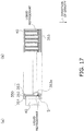
- FIG. 7 is a cross-sectional view of case in which the refrigerant header 50 has been cut along the lengthwise direction thereof, when the heat exchanger 10 has been installed in a state with the refrigerant headers 50 and the multi-hole flat tubes 40 arranged extending along the horizontal direction.
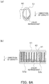
- FIG. 8A (a) is a cross-sectional view of a case in which the refrigerant header 50 has been cut along a direction orthogonal to the lengthwise direction thereof, when the heat exchanger 10 has been installed in a state with the refrigerant headers 50 and the multi-hole flat tubes 40 arranged extending along the horizontal direction.
- FIG. 8A (a) is a cross-sectional view of a case in which the refrigerant header 50 has been cut along a direction orthogonal to the lengthwise direction thereof, when the heat exchanger 10 has been installed in a state with the refrigerant headers 50 and the multi-hole flat tubes 40 arranged extending along the horizontal direction.
- FIG. 8A (b) is a cross-sectional view of a case in which the refrigerant header 50 has been cut along the lengthwise direction thereof, when the heat exchanger 10 has been installed in a state with the refrigerant headers 50 and the multi-hole flat tubes 40 arranged extending along the horizontal direction.
- the "refrigerant headers 50 being arranged so as to extend along the horizontal direction” herein refers to a range of instances from those in which the refrigerant headers 50 are not inclined at all with respect to a horizontal plane, to those in which they inclined by about ⁇ 15° with respect to a horizontal plane.
- the heat exchanger 10 oriented in a state in which the refrigerant headers 50 and the multi-hole flat tubes 40 are arranged so as to extend along the horizontal direction (a state of zero inclination with respect to a horizontal plane), is installed within the refrigeration apparatus 91.
- FIG. 4 shows the heat exchanger 10 as-installed installation by the installation means of the present embodiment, viewed from above.
- the plurality of refrigerant flow channels 41 in the present embodiment, 12 formed in the multi-hole flat tubes 40 are arranged so as to line up along the vertical direction, as shown in FIG. 7 .
- the "plurality of refrigerant flow channels 41 are arranged so as to line up along the vertical direction” refers to a range of instances from those in which the plurality of refrigerant flow channels 41 are not inclined at all with respect to a vertical plane, to those in which they inclined by about ⁇ 15° with respect to a vertical plane.
- the liquid refrigerant can be expelled from the refrigerant flow channel 41 that, of the refrigerant flow channels 41 lined up in the vertical direction, is positioned in the lowermost part.
- FIG. 9 is a view of a heat exchanger of the same configuration as the heat exchanger 10 of the present embodiment, shown in a state of being installed in a state in which the refrigerant headers 50 are arranged extending along the vertical direction (top-to-bottom direction), and the multi-hole flat tubes 40 are arranged extending along the horizontal direction.
- FIG. 10 is a view of the heat exchanger installed in the state shown in FIG. 9 , showing a state in which, in a case in which gaseous refrigerant has condensed into liquid refrigerant, the liquid refrigerant pools in the refrigerant header 50 interior.
- FIG. 10 is a view of the heat exchanger installed in the state shown in FIG. 9 , showing a state in which, in a case in which gaseous refrigerant has condensed into liquid refrigerant, the liquid refrigerant pools in the refrigerant header 50 interior.
- FIG. 11 is a view of predicted temperature distribution of the refrigerant and the water at points (A-F) in the heat exchanger installed in the state shown in FIG. 9 .
- the heat exchanger installed in the state shown in FIG. 9 i.e., in a state in which the refrigerant headers 50 are arranged extending along the vertical direction and the multi-hole flat tubes 40 are arranged extending along the horizontal direction, is denoted by symbol 510.
- point A refers to the first header part 55a and the first section 34a in FIG. 9
- point B refers to the first header part 54a and the first section 35a in FIG. 9
- point C refers to the second header part 55b and the second section 34b in FIG.
- point D refers to the second header part 54b and the second section 35b in FIG. 9
- point E refers to the third header part 55c and the third section 34c in FIG. 9
- point F refers to the third header part 54c and the third section 35c in FIG. 9 .
- the heat exchanger 510 constituted by stacking the plurality of multi-hole flat tubes 40 and the plurality of flat tubes 20 in alternating fashion, in cases in which a refrigerant that undergoes a phase change during heat exchange is employed as the refrigerant flowing through the refrigerant flow channels 41 of the multi-hole flat tubes 40, when the refrigerant headers 51, 52 are arranged to extend along the vertical direction as shown in FIG. 9 , due to gravity, the liquid refrigerant produced during condensation is retained respectively in the bottom parts of the first spaces 51a, 52a, the second spaces 51b, 52b, and the third spaces 51c, 52c which are provided in the refrigerant headers 51, 52 (see FIG. 10 ).
- all of the refrigerant flow channels 41 of the multi-hole flat tubes 40 that, of the plurality of multi-hole flat tubes 40 connected to the refrigerant headers 50, are those positioned at the bottom parts of the spaces 51a, 52a, 51b, 52b, 51c, 52c are submerged in the liquid refrigerant.
- the overall function of the heat exchanger 510 will be diminished due to a decline in the amount of heat exchange by the multi-hole flat tubes 40.
- the refrigerant headers 50 are arranged so as to extend along the horizontal direction. For this reason, as shown in FIG. 9 , as compared with the case in which the refrigerant headers are arranged to extend along the vertical direction, even when the liquid refrigerant produced during refrigerant condensation has pooled in the refrigerant header 50 interior, the surface level height of the pooled refrigerant can be lowered. Consequently, as shown in FIG.
- the multi-hole flat tubes 40 are arranged to extend along the horizontal direction.
- the multi-hole flat tubes 40 are arranged to extend along the horizontal direction in this manner, there is no need to lift the liquid refrigerant against gravity, as is the case in which the multi-hole flat tubes are arranged to extend along the vertical direction, and therefore increase in pressure loss can be kept smaller than when the multi-hole flat tubes are arranged to extend along the vertical direction.
- the plurality of refrigerant flow channels 41 formed in the multi-hole flat tubes 40 are arranged to line up along the vertical direction. For this reason, even if gaseous refrigerant condenses into liquid refrigerant, the liquid refrigerant is transported from a refrigerant flow channel 41 that, of the refrigerant flow channels 41 lined up along the vertical direction, is one positioned to the bottom.
- FIG. 12 is a view showing a state in which a heat exchanger has been installed in a state in which the refrigerant headers 50 are arranged to extend along the horizontal direction, and the multi-hole flat tubes 40 are arranged to extend along the vertical direction.
- FIG. 13(a) is a cross-sectional view of the refrigerant header 52 of the heat exchanger in the state shown in FIG. 12 , in the case of being cut along a direction orthogonal to the lengthwise direction thereof.
- FIG. 13(b) is a cross-sectional view of the refrigerant header 52 of the heat exchanger in the state shown in FIG. 12 , in the case of being cut along the lengthwise direction thereof.
- FIG. 13(a) is a cross-sectional view of the refrigerant header 52 of the heat exchanger in the state shown in FIG. 12 , in the case of being cut along the lengthwise direction thereof.
- FIG. 14(a) is a cross-sectional view of the refrigerant header 51 of the heat exchanger in the state shown in FIG. 12 , in the case of being cut along a direction orthogonal to the lengthwise direction thereof.
- FIG. 14(b) is a cross-sectional view of the refrigerant header 51 of the heat exchanger in the state shown in FIG. 12 , in the case of being cut along the lengthwise direction thereof.
- the refrigerant headers 50 and the multi-hole flat tubes 40 are arranged so as to extend along the horizontal direction.
- the multi-hole flat tubes need not be arranged to extend along the horizontal direction, as long as the refrigerant headers are arranged so as to extend along the horizontal direction.
- the heat exchanger 110 shown in FIG. 12 has the same constitution as the heat exchanger 10 of the aforedescribed embodiment, and therefore the parts that constitute the heat exchanger 110 are assigned the same symbols as in the aforedescribed embodiment, and descriptions thereof are omitted.
- the refrigerant header 52 is positioned to the top, and the refrigerant header 51 is positioned to the bottom.
- the refrigerant enters the first header part 55a of the refrigerant header 52, branches into four of the multi-hole flat tubes 40 and flows from top to bottom to therein, and converges in the first header part 54a of the refrigerant header 51.
- the refrigerant branches from the first header part 54a into three of the multi-hole flat tubes 40 and flows from bottom to top therein, and converges in the second header part 55b of the refrigerant header 52.
- the refrigerant branches from the second header part 55b into three of the multi-hole flat tubes 40 and flows from top to bottom therein, and converges in the second header part 54b of the refrigerant header 51.
- the refrigerant branches from the second header part 54b into three of the multi-hole flat tubes 40 and flows from bottom to top therein, and converges in the third header part 55c of the refrigerant header 52.
- the refrigerant branches from the third header part 55c into three of the multi-hole flat tubes 40 and flows from top to bottom therein, converges in the third header part 54c of the refrigerant header 51, and outflows from the heat exchanger 110.
- the refrigerant headers 50 of this heat exchanger 110 are arranged to extend in the horizontal direction, and therefore, as shown in FIG. 9 , as compared with the case in which the refrigerant headers 50 are arranged to extend in the vertical direction, even when gaseous refrigerant has condensed and liquid refrigerant has pooled in the refrigerant header 50 interior, the surface level height of the pooled refrigerant can be lowered. Therefore, the risk that all of the refrigerant flow channels 41 of the prescribed multi-hole flat tubes 40 will become submerged in the liquid refrigerant can be reduced, and as a result, uneven flow of the refrigerant in the multi-hole flat tubes 40 can be reduced.
- the multi-hole flat tubes 40 By arranging the multi-hole flat tubes 40 to extend along the vertical direction, the multi-hole flat tubes 40 are uniform in height, as shown in FIG. 12 . For this reason, as shown in FIG. 13 , even when the liquid refrigerant is retained in the refrigerant header 52 interior, the inlets of the multi-hole flat tubes 40 (the end faces of the refrigerant flow channels 41) and the surface level of the liquid refrigerant are generally parallel, and the liquid refrigerant is readily distributed uniformly among the multi-hole flat tubes 40. As a result, uneven flow of the refrigerant can be reduced.
- the multi-hole flat tubes 40 to extend along the vertical direction makes it necessary to lift the condensed liquid refrigerant against gravity, increasing the pressure loss of the refrigerant when lifted. Thus, the condensation temperature drops, and the temperature differential between the refrigerant and the water is small, so that the amount of heat exchange is smaller. Further, as shown in FIG. 14 , when the liquid refrigerant is retained within the refrigerant header 51 which is arranged at the bottom, there is a possibility that the amount of refrigerant filling the header will increase. Consequently, during installation of the heat exchanger in the refrigeration apparatus, it is more preferable for the multi-hole flat tubes 40 to be arranged to extend along the horizontal direction, than to be arranged to extend along the vertical direction.
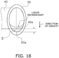
- the cross-section of the refrigerant header 50 when cut in a direction orthogonal to the lengthwise direction thereof is ellipsoidal and the multi-hole flat tube 40 is fitted into the refrigerant header 50 in such a way that, once the heat exchanger 10 has been installed a gap S is formed between the bottom surface 50a of the refrigerant header 50 interior and the bottom end 40a of the multi-hole flat tube 40.
- the shape of the refrigerant header 50 is not limited thereto, as long as the gap S can be provided between the bottom surface 50a of the refrigerant header 50 interior and the bottom end 40a of the multi-hole flat tube 40, with the heat exchanger 10 in the installed state.
- the refrigerant header may have a semicircular cross-section when cut in a direction orthogonal to the lengthwise direction thereof.
- a refrigerant header 150 may curve so as to protrude out towards the direction in which the multi-hole flat tube 40 is fitted therein, as shown in FIG. 15 ; or a refrigerant header 250 may curve so as to protrude out towards opposite direction from the direction in which the multi-hole flat tube 40 is fitted therein, as shown in FIG. 16 .
- the liquid refrigerant is able to pool in the bottom space of the refrigerant header 150, 250.
- the cross-sectional shape of the refrigerant header 50 when cut in a direction orthogonal to the lengthwise direction thereof may differ in the top-to-bottom direction, with the heat exchanger 10 in the installed state.
- a refrigerant header 350 is a stacked type header having a bonded panel 351, a spacer 352, and a side panel 353, a portion of the side panel 353 may be constituted so as to protrude outward.
- the multi-hole flat tube 40 may be fitted eccentrically into the refrigerant header 50, thus increasing the size of the gap S between the bottom surface 50a of the refrigerant header 50 interior and the bottom end 40a of the multi-hole flat tube 40.
- the liquid refrigerant pools in the space during operation of the heat exchanger 10, and the surface level thereof reaches the liquid refrigerant flow channel 41 that, of the liquid refrigerant flow channels 41 lined up along the vertical direction, is in the bottommost part, whereby the liquid refrigerant can be discharged from the liquid refrigerant flow channel 41 positioned in the bottommost part.
- the plurality of refrigerant flow channels 41 formed in the multi-hole flat tubes 40 are all identical. Therefore, the planar dimensions of the flow channel cross-sections of all of the refrigerant flow channels 41 are identical.
- the refrigerant flow channels 441a, 441c that are positioned at the ends among the plurality of refrigerant flow channels 441 formed in the multi-hole flat tubes 440 to be provided with a flow channel cross-section larger than the flow channel cross-section of the other refrigerant flow channels 441b.
- the planar dimensions of the flow channel cross-section of the lowermost tier refrigerant flow channel 441a that is positioned lowermost among the plurality of refrigerant flow channels 441 lined up in the vertical direction (direction of gravity) are larger than the planar dimensions of the flow channel cross-section of the upper tier refrigerant flow channels 441b which are positioned above the lowermost tier refrigerant flow channel 441a, and therefore, as compared with the case in which the flow channel cross-sections of all of the refrigerant flow channels 441 have identical planar dimensions, flow resistance in the lowermost tier refrigerant flow channel 441a can be reduced, and as a result, the liquid refrigerant pooling within the refrigerant header 350 can flow smoothly. As a result, the heat exchange efficiency of the heat exchanger 10 can be improved.
- grooves 442 for heat transfer promotion may be formed on surfaces constituting the refrigerant flow channels 441b other than the refrigerant flow channels 441a, 441c positioned at the ends, among the plurality of refrigerant flow channels 441 formed in the multi-hole flat tubes 440.
- the grooves 442 for heat transfer promotion need not be formed on the surfaces constituting the refrigerant flow channels 441a, 441c positioned at the ends, among the plurality of refrigerant flow channels 441 formed in the multi-hole flat tubes 440.
- the flow resistance in the lowermost tier refrigerant flow channel 441a can be reduced, and as a result, the liquid refrigerant pooled within the refrigerant header 350 can flow smoothly. As a result, the heat exchange efficiency of the heat exchanger 10 can be improved.
- the multi-hole flat tubes 440 of the present modification can be applied not only to the aforedescribed embodiment, but also to heat exchangers according to the other modification.
- the multi-hole flat tubes 440 of the present modification can be applied to refrigerant headers constituted to have a larger space for the liquid refrigerant to pool, as in the aforedescribed Modification B, the heat exchange efficiency of the heat exchanger 10 can be improved further.
- FIG. 20 is a schematic view depicting the installation state of a heat exchanger 10 according to Modification D, when the heat exchanger 10 is viewed from the refrigerant header 51 side.
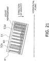
- FIG. 21 is a cross-sectional view of the refrigerant header 51 in the state shown in FIG. 20 .
- FIG. 22 is a schematic view describing the installation state of the heat exchanger 10 according to Modification D. The hatched section in FIG. 22 indicates a heat transfer portion 39.
- Draining of the heat exchanger 10 specifically refers to an operation of opening the inlet-side cock 80 provided to the inlet section 37 of the communicating portions 31, 32 of the flat tubes 20, and the outlet-side cock 81 provided to the outlet section 38, and discharging the water in the heat exchanger 10 to the outside.
- the heat exchanger 10 may be installed within the refrigeration apparatus 91 in such a way as to be inclined by a prescribed angle (within a range of 0° to ⁇ 15°) with respect to a horizontal plane, such that the ends of the communicating portions 31, 32 at either the inlet section 37 side or the outlet section 38 side thereof are lower than the ends of the other.
- the water within the heat exchanger 10 can be more easily discharged from the inlet-side cock 80, than when the heat exchanger 10 is installed in a state in which the communicating portions 31, 32 are not inclined at all with respect to the horizontal plane.
- the respective ends of the communicating portions 31, 32 at the side where the inlet section 37 is located are positioned below the respective ends of the communicating portions 31, 32 at the side where the outlet section 38 is located
- the respective ends of the refrigerant headers 51, 52 at the side where the outlet section 58 is located will be positioned below the respective ends of the refrigerant headers 51, 52 at the side where the inlet section 57 is located (see FIGS. 20 and 21 ).
- the gaseous refrigerant that has entered from the inlet section 57 undergoes phase change from a gaseous refrigerant to a liquid refrigerant through heat exchange, and the outflow from the outlet section 58 is primarily the liquid refrigerant.
- the heat exchanger 10 functions as a condenser
- the heat exchanger 10 by installing the heat exchanger 10 in such a way that the respective ends of the refrigerant headers 51, 52 at the side where the outlet section 58 is located are positioned below the respective ends of the refrigerant headers 51, 52 at the side where the inlet section 57 is located, the liquid refrigerant flows out from the outlet section 58 more easily than when the heat exchanger 10 is installed in a state in which the refrigerant headers 51, 52 are not inclined at all with respect to the horizontal plane, and therefore the risk of the liquid refrigerant collecting within the heat exchanger 10 can be reduced.
- heat transfer portion which is the section that contacts the multi-hole flat tube 40
- the heat transfer portion 39 it is more difficult for water to collect in the heat transfer portion 39, as compared with the case in which the heat exchanger 10 is installed such that the heat transfer portion 39 is arranged below the communicating portions 31, 32, and therefore the water that has pooled within the heat exchanger 10 is easily discharged. In so doing, the operation to drain the heat exchanger 10 can be simplified.
- the present invention relates to a heat exchanger capable of reducing any decrease in performance, the heat exchanger being effective for applications oriented to heat exchangers in which a plurality of flat tubes and a plurality of multi-hole flat tubes are stacked in alternating fashion, and which are provided with headers extending in a direction intersecting the lengthwise direction of the multi-hole flat tubes.
- PATENT LITERATURE 1 Japanese Laid-Open Patent Application 2007-17133
Landscapes
- Engineering & Computer Science (AREA)
- Physics & Mathematics (AREA)
- Thermal Sciences (AREA)
- Mechanical Engineering (AREA)
- General Engineering & Computer Science (AREA)
- Geometry (AREA)
- Heat-Exchange Devices With Radiators And Conduit Assemblies (AREA)
Claims (6)
- Échangeur de chaleur pour la réalisation de l'échange de chaleur entre un réfrigérant qui subit un changement de phase pendant l'échange de chaleur, et un autre milieu de chauffage, comprenant :des collecteurs (50) dans lesquels le réfrigérant s'écoule au travers de l'intérieur ;une pluralité de tubes plats à orifices multiples (440) qui s'étendent dans une direction croisant la direction de longueur des collecteurs, et dans lesquels est formée une pluralité de canaux de flux de réfrigérant (441) au travers de l'intérieur desquels le réfrigérant s'écoule ; etune pluralité de tubes plats (20) au travers de l'intérieur desquels l'autre milieu de chauffage s'écoule, et qui sont empilés en alternance par rapport à la pluralité de tubes plats à orifices multiples ; dans lequelles collecteurs (50) étant agencés de manière à s'étendre le long d'une direction horizontale,les tubes plats à orifices multiples (440) sont agencés de manière à s'étendre le long d'une direction horizontale,la pluralité de canaux de flux de réfrigérant (441) formés dans les tubes plats à orifices multiples (440) est agencée de manière à s'aligner le long d'une direction verticale, caractérisé en ce quela section transversale du canal de flux de réfrigérant de niveau inférieur (441a) positionné le plus bas parmi la pluralité de canaux de flux de réfrigérant (441) est plus grande que la section transversale de canaux de flux de réfrigérant de niveau supérieur (441b) positionnés au-dessus du canal de flux de réfrigérant de niveau inférieur (441a).
- Échangeur de chaleur selon la revendication 1, dans lequel,
une fois que les tubes plats à orifices multiples ont été insérés dans les collecteurs, une fente est présente entre la surface inférieure de l'intérieur de collecteur et l'extrémité inférieure des tubes plats à orifices multiples. - Échangeur de chaleur selon la revendication 1 ou 2, dans lequel
des rainures pour favoriser le transfert thermique sont formées sur des surfaces constituant les canaux de flux de réfrigérant de niveau supérieur mais ne sont pas formées sur des surfaces constituant le canal de flux de réfrigérant de niveau inférieur. - Échangeur de chaleur selon l'une quelconque des revendications 1 à 3, dans lequel
les collecteurs incluent une section d'entrée (57) pour le réfrigérant et une section de sortie (58) pour le réfrigérant,
la pluralité de tubes plats à orifices multiples communique via des portions de communication (31, 32) qui incluent une section d'entrée (37) pour l'autre milieu de chauffage et une section de sortie (38) pour l'autre milieu de chauffage,
les portions de communication s'étendent le long de la direction d'extension des collecteurs, et
les collecteurs sont agencés de sorte que le côté de section de sortie de réfrigérant soit positionné sous le côté de section d'entrée de réfrigérant. - Échangeur de chaleur selon la revendication 4, dans lequel
les tubes plats incluent une portion de transfert de chaleur (39) touchant les tubes plats à orifices multiples, et
les portions de communication sont agencées sous la portion de transfert de chaleur. - Échangeur de chaleur selon l'une quelconque des revendications 1 à 5, dans lequel
les tubes plats à orifices multiples sont agencés de manière à s'étendre le long d'une direction verticale.
Applications Claiming Priority (3)
| Application Number | Priority Date | Filing Date | Title |
|---|---|---|---|
| JP2012281797 | 2012-12-25 | ||
| JP2013205780A JP5790730B2 (ja) | 2012-12-25 | 2013-09-30 | 熱交換器 |
| PCT/JP2013/081173 WO2014103563A1 (fr) | 2012-12-25 | 2013-11-19 | Echangeur thermique |
Publications (3)
| Publication Number | Publication Date |
|---|---|
| EP2942594A1 EP2942594A1 (fr) | 2015-11-11 |
| EP2942594A4 EP2942594A4 (fr) | 2016-10-26 |
| EP2942594B1 true EP2942594B1 (fr) | 2019-04-24 |
Family
ID=51020657
Family Applications (1)
| Application Number | Title | Priority Date | Filing Date |
|---|---|---|---|
| EP13869525.9A Active EP2942594B1 (fr) | 2012-12-25 | 2013-11-19 | Echangeur thermique |
Country Status (5)
| Country | Link |
|---|---|
| US (1) | US9791213B2 (fr) |
| EP (1) | EP2942594B1 (fr) |
| JP (1) | JP5790730B2 (fr) |
| CN (1) | CN104884891B (fr) |
| WO (1) | WO2014103563A1 (fr) |
Families Citing this family (19)
| Publication number | Priority date | Publication date | Assignee | Title |
|---|---|---|---|---|
| FR3025596B1 (fr) * | 2014-09-08 | 2016-12-23 | Valeo Systemes Thermiques | Tube a reservoir de materiau a changement de phase pour echangeur de chaleur |
| JP6531380B2 (ja) * | 2014-12-12 | 2019-06-19 | ダイキン工業株式会社 | 熱交換器 |
| CN105133258A (zh) * | 2015-09-21 | 2015-12-09 | 蒋凤英 | 一种洗衣机用热交换器 |
| CN105133273A (zh) * | 2015-09-21 | 2015-12-09 | 蒋凤英 | 一种具有热交换器的洗衣机 |
| JP2017166728A (ja) * | 2016-03-15 | 2017-09-21 | 三菱重工サーマルシステムズ株式会社 | 熱交換器の評価装置、熱交換器の評価方法、熱交換器の製造方法、並びに熱交換器の設計方法 |
| JP2018096568A (ja) * | 2016-12-09 | 2018-06-21 | 株式会社デンソー | 熱交換器 |
| US11181328B2 (en) | 2017-03-27 | 2021-11-23 | Daikin Industries, Ltd. | Heat exchanger and air conditioner |
| JP6369648B1 (ja) | 2017-03-27 | 2018-08-08 | ダイキン工業株式会社 | 熱交換器および空気調和装置 |
| EP3489604B1 (fr) * | 2017-11-24 | 2020-12-23 | TitanX Holding AB | Condenseur de véhicule |
| JP2019120449A (ja) * | 2017-12-28 | 2019-07-22 | ダイキン工業株式会社 | 冷凍装置の熱源ユニット |
| JP2019120448A (ja) * | 2017-12-28 | 2019-07-22 | ダイキン工業株式会社 | 冷凍装置の熱源ユニット |
| US11498162B2 (en) | 2018-09-21 | 2022-11-15 | Johnson Controls Tyco IP Holdings LLP | Heat exchanger tube with flattened draining dimple |
| JP7227457B2 (ja) * | 2018-11-07 | 2023-02-22 | ダイキン工業株式会社 | 熱交換器及び空調機 |
| CN110030846A (zh) * | 2019-04-10 | 2019-07-19 | 清华大学 | 三介质换热器 |
| USD982730S1 (en) * | 2019-06-18 | 2023-04-04 | Caterpillar Inc. | Tube |
| JP6822525B2 (ja) * | 2019-06-28 | 2021-01-27 | ダイキン工業株式会社 | 熱交換器およびヒートポンプ装置 |
| JP7158601B2 (ja) * | 2019-10-23 | 2022-10-21 | 三菱電機株式会社 | 熱交換器及び冷凍サイクル装置 |
| US11982459B2 (en) * | 2020-08-26 | 2024-05-14 | Gd Midea Heating & Ventilating Equipment Co., Ltd. | Air conditioning apparatus and electric control box |
| CN113102452A (zh) * | 2021-04-02 | 2021-07-13 | 广东亿云智能环保科技有限公司 | 一种可回收余热的大型餐厨垃圾生物降解处理设备 |
Family Cites Families (21)
| Publication number | Priority date | Publication date | Assignee | Title |
|---|---|---|---|---|
| JP3300192B2 (ja) * | 1995-03-27 | 2002-07-08 | サンデン株式会社 | 熱交換器 |
| JPH1123086A (ja) * | 1997-07-01 | 1999-01-26 | Daikin Ind Ltd | 空冷吸収式冷凍機及びその凝縮器 |
| GB2344643B (en) * | 1998-12-07 | 2002-06-26 | Serck Heat Transfer Ltd | Heat exchanger core connection |
| JP3812792B2 (ja) * | 1999-08-06 | 2006-08-23 | 株式会社豊田自動織機 | 固気反応粉粒充填間接熱交換器 |
| JP2001221580A (ja) * | 2000-02-08 | 2001-08-17 | Sanden Corp | 熱交換器 |
| JP4166591B2 (ja) * | 2003-02-13 | 2008-10-15 | カルソニックカンセイ株式会社 | 熱交換器 |
| EP1844288B1 (fr) | 2005-02-02 | 2011-10-19 | Carrier Corporation | Échangeur de chaleur à détente du fluide dans le collecteur |
| JP2007017132A (ja) * | 2005-07-11 | 2007-01-25 | Denso Corp | 熱交換用チューブおよび熱交換器 |
| JP2007017133A (ja) * | 2005-07-11 | 2007-01-25 | Denso Corp | 熱交換器 |
| JP2007333304A (ja) * | 2006-06-15 | 2007-12-27 | Valeo Thermal Systems Japan Corp | 熱交換器 |
| JP2009204277A (ja) * | 2008-02-29 | 2009-09-10 | Nippon Light Metal Co Ltd | 熱交換器 |
| JP2009287907A (ja) * | 2008-06-02 | 2009-12-10 | Showa Denko Kk | 熱交換器 |
| US8234881B2 (en) * | 2008-08-28 | 2012-08-07 | Johnson Controls Technology Company | Multichannel heat exchanger with dissimilar flow |
| CN101482378B (zh) * | 2008-12-29 | 2011-08-10 | 清华大学 | 一种分段式汽液相变换热器的汽液分离方法及换热器 |
| JP5408017B2 (ja) * | 2009-06-05 | 2014-02-05 | 株式会社デンソー | 蓄冷熱交換器 |
| JP2011033290A (ja) * | 2009-08-04 | 2011-02-17 | Mitsubishi Electric Corp | 熱交換器、空気調和装置およびヒートポンプシステム |
| CN101672581A (zh) * | 2009-09-25 | 2010-03-17 | 北京龙源冷却技术有限公司 | 一种换热器 |
| JP2011106738A (ja) * | 2009-11-17 | 2011-06-02 | Mitsubishi Electric Corp | 熱交換器およびヒートポンプシステム |
| WO2012017681A1 (fr) * | 2010-08-05 | 2012-02-09 | 三菱電機株式会社 | Échangeur de chaleur et dispositif de conditionnement d'air et de réfrigération |
| JP5670672B2 (ja) * | 2010-09-03 | 2015-02-18 | シーアイ化成株式会社 | 熱交換器 |
| JP5206830B2 (ja) * | 2011-03-25 | 2013-06-12 | ダイキン工業株式会社 | 熱交換器 |
-
2013
- 2013-09-30 JP JP2013205780A patent/JP5790730B2/ja active Active
- 2013-11-19 US US14/654,799 patent/US9791213B2/en active Active
- 2013-11-19 CN CN201380067863.4A patent/CN104884891B/zh active Active
- 2013-11-19 EP EP13869525.9A patent/EP2942594B1/fr active Active
- 2013-11-19 WO PCT/JP2013/081173 patent/WO2014103563A1/fr active Application Filing
Non-Patent Citations (1)
| Title |
|---|
| None * |
Also Published As
| Publication number | Publication date |
|---|---|
| US20150338168A1 (en) | 2015-11-26 |
| CN104884891A (zh) | 2015-09-02 |
| JP5790730B2 (ja) | 2015-10-07 |
| JP2014142165A (ja) | 2014-08-07 |
| EP2942594A1 (fr) | 2015-11-11 |
| WO2014103563A1 (fr) | 2014-07-03 |
| CN104884891B (zh) | 2018-04-06 |
| US9791213B2 (en) | 2017-10-17 |
| EP2942594A4 (fr) | 2016-10-26 |
Similar Documents
| Publication | Publication Date | Title |
|---|---|---|
| EP2942594B1 (fr) | Echangeur thermique | |
| JP6701372B2 (ja) | 熱交換器 | |
| JP4055449B2 (ja) | 熱交換器およびこれを用いた空気調和機 | |
| US9212836B2 (en) | Heat exchanger | |
| US10371422B2 (en) | Condenser with tube support structure | |
| JP4180801B2 (ja) | 冷凍空調サイクル装置 | |
| US10612856B2 (en) | Heat exchanger and air conditioning system | |
| EP3183528B1 (fr) | Échangeur de chaleur à micro-canal à faible charge de réfrigérant | |
| JP7364930B2 (ja) | 熱交換器 | |
| JP2007212091A (ja) | シェルアンドチューブ型凝縮器 | |
| EP2932162B1 (fr) | Compresseur frigorifique basse pression | |
| EP3875878B1 (fr) | Échangeur de chaleur et dispositif à cycle de réfrigération | |
| CN108224857B (zh) | 具有冷凝器的储液罐 | |
| US20220404099A1 (en) | Heat exchanger built with additive manufacturing | |
| JP3911604B2 (ja) | 熱交換器および冷凍サイクル | |
| CN108931151A (zh) | 用于冷却电子设备外壳的热交换器 | |
| JP2003028539A (ja) | 熱交換器および冷凍サイクル装置 | |
| KR100812497B1 (ko) | 고압 열교환기의 헤더 | |
| CN111316053B (zh) | 用于降膜蒸发器管板的系统和方法 | |
| KR20090120078A (ko) | 고압 열교환기의 헤더 | |
| US20190041135A1 (en) | Double plated heat exchanger | |
| JP2010078171A (ja) | 内部熱交換器 | |
| JP2011133188A (ja) | 内部熱交換器 |
Legal Events
| Date | Code | Title | Description |
|---|---|---|---|
| PUAI | Public reference made under article 153(3) epc to a published international application that has entered the european phase |
Free format text: ORIGINAL CODE: 0009012 |
|
| 17P | Request for examination filed |
Effective date: 20150625 |
|
| AK | Designated contracting states |
Kind code of ref document: A1 Designated state(s): AL AT BE BG CH CY CZ DE DK EE ES FI FR GB GR HR HU IE IS IT LI LT LU LV MC MK MT NL NO PL PT RO RS SE SI SK SM TR |
|
| AX | Request for extension of the european patent |
Extension state: BA ME |
|
| DAX | Request for extension of the european patent (deleted) | ||
| A4 | Supplementary search report drawn up and despatched |
Effective date: 20160923 |
|
| RIC1 | Information provided on ipc code assigned before grant |
Ipc: F28F 1/02 20060101ALI20160919BHEP Ipc: F28D 7/00 20060101ALI20160919BHEP Ipc: F28F 9/26 20060101AFI20160919BHEP |
|
| GRAP | Despatch of communication of intention to grant a patent |
Free format text: ORIGINAL CODE: EPIDOSNIGR1 |
|
| STAA | Information on the status of an ep patent application or granted ep patent |
Free format text: STATUS: GRANT OF PATENT IS INTENDED |
|
| INTG | Intention to grant announced |
Effective date: 20181008 |
|
| GRAS | Grant fee paid |
Free format text: ORIGINAL CODE: EPIDOSNIGR3 |
|
| RIN1 | Information on inventor provided before grant (corrected) |
Inventor name: YOSHIOKA, SHUN Inventor name: MATSUO, NOBUHIKO Inventor name: AKAI, KANJI Inventor name: OHTA, SHOUGO Inventor name: KAGOHARA, KENTO Inventor name: YOSHIDA, KAORI |
|
| GRAA | (expected) grant |
Free format text: ORIGINAL CODE: 0009210 |
|
| STAA | Information on the status of an ep patent application or granted ep patent |
Free format text: STATUS: THE PATENT HAS BEEN GRANTED |
|
| AK | Designated contracting states |
Kind code of ref document: B1 Designated state(s): AL AT BE BG CH CY CZ DE DK EE ES FI FR GB GR HR HU IE IS IT LI LT LU LV MC MK MT NL NO PL PT RO RS SE SI SK SM TR |
|
| REG | Reference to a national code |
Ref country code: GB Ref legal event code: FG4D |
|
| REG | Reference to a national code |
Ref country code: CH Ref legal event code: EP |
|
| REG | Reference to a national code |
Ref country code: AT Ref legal event code: REF Ref document number: 1124645 Country of ref document: AT Kind code of ref document: T Effective date: 20190515 Ref country code: IE Ref legal event code: FG4D |
|
| REG | Reference to a national code |
Ref country code: DE Ref legal event code: R096 Ref document number: 602013054470 Country of ref document: DE |
|
| REG | Reference to a national code |
Ref country code: NL Ref legal event code: MP Effective date: 20190424 |
|
| REG | Reference to a national code |
Ref country code: LT Ref legal event code: MG4D |
|
| PG25 | Lapsed in a contracting state [announced via postgrant information from national office to epo] |
Ref country code: NL Free format text: LAPSE BECAUSE OF FAILURE TO SUBMIT A TRANSLATION OF THE DESCRIPTION OR TO PAY THE FEE WITHIN THE PRESCRIBED TIME-LIMIT Effective date: 20190424 |
|
| PG25 | Lapsed in a contracting state [announced via postgrant information from national office to epo] |
Ref country code: FI Free format text: LAPSE BECAUSE OF FAILURE TO SUBMIT A TRANSLATION OF THE DESCRIPTION OR TO PAY THE FEE WITHIN THE PRESCRIBED TIME-LIMIT Effective date: 20190424 Ref country code: LT Free format text: LAPSE BECAUSE OF FAILURE TO SUBMIT A TRANSLATION OF THE DESCRIPTION OR TO PAY THE FEE WITHIN THE PRESCRIBED TIME-LIMIT Effective date: 20190424 Ref country code: PT Free format text: LAPSE BECAUSE OF FAILURE TO SUBMIT A TRANSLATION OF THE DESCRIPTION OR TO PAY THE FEE WITHIN THE PRESCRIBED TIME-LIMIT Effective date: 20190824 Ref country code: SE Free format text: LAPSE BECAUSE OF FAILURE TO SUBMIT A TRANSLATION OF THE DESCRIPTION OR TO PAY THE FEE WITHIN THE PRESCRIBED TIME-LIMIT Effective date: 20190424 Ref country code: AL Free format text: LAPSE BECAUSE OF FAILURE TO SUBMIT A TRANSLATION OF THE DESCRIPTION OR TO PAY THE FEE WITHIN THE PRESCRIBED TIME-LIMIT Effective date: 20190424 Ref country code: NO Free format text: LAPSE BECAUSE OF FAILURE TO SUBMIT A TRANSLATION OF THE DESCRIPTION OR TO PAY THE FEE WITHIN THE PRESCRIBED TIME-LIMIT Effective date: 20190724 Ref country code: ES Free format text: LAPSE BECAUSE OF FAILURE TO SUBMIT A TRANSLATION OF THE DESCRIPTION OR TO PAY THE FEE WITHIN THE PRESCRIBED TIME-LIMIT Effective date: 20190424 Ref country code: HR Free format text: LAPSE BECAUSE OF FAILURE TO SUBMIT A TRANSLATION OF THE DESCRIPTION OR TO PAY THE FEE WITHIN THE PRESCRIBED TIME-LIMIT Effective date: 20190424 |
|
| PG25 | Lapsed in a contracting state [announced via postgrant information from national office to epo] |
Ref country code: GR Free format text: LAPSE BECAUSE OF FAILURE TO SUBMIT A TRANSLATION OF THE DESCRIPTION OR TO PAY THE FEE WITHIN THE PRESCRIBED TIME-LIMIT Effective date: 20190725 Ref country code: BG Free format text: LAPSE BECAUSE OF FAILURE TO SUBMIT A TRANSLATION OF THE DESCRIPTION OR TO PAY THE FEE WITHIN THE PRESCRIBED TIME-LIMIT Effective date: 20190724 Ref country code: PL Free format text: LAPSE BECAUSE OF FAILURE TO SUBMIT A TRANSLATION OF THE DESCRIPTION OR TO PAY THE FEE WITHIN THE PRESCRIBED TIME-LIMIT Effective date: 20190424 Ref country code: RS Free format text: LAPSE BECAUSE OF FAILURE TO SUBMIT A TRANSLATION OF THE DESCRIPTION OR TO PAY THE FEE WITHIN THE PRESCRIBED TIME-LIMIT Effective date: 20190424 Ref country code: LV Free format text: LAPSE BECAUSE OF FAILURE TO SUBMIT A TRANSLATION OF THE DESCRIPTION OR TO PAY THE FEE WITHIN THE PRESCRIBED TIME-LIMIT Effective date: 20190424 |
|
| REG | Reference to a national code |
Ref country code: AT Ref legal event code: MK05 Ref document number: 1124645 Country of ref document: AT Kind code of ref document: T Effective date: 20190424 |
|
| PG25 | Lapsed in a contracting state [announced via postgrant information from national office to epo] |
Ref country code: IS Free format text: LAPSE BECAUSE OF FAILURE TO SUBMIT A TRANSLATION OF THE DESCRIPTION OR TO PAY THE FEE WITHIN THE PRESCRIBED TIME-LIMIT Effective date: 20190824 |
|
| REG | Reference to a national code |
Ref country code: DE Ref legal event code: R097 Ref document number: 602013054470 Country of ref document: DE |
|
| PG25 | Lapsed in a contracting state [announced via postgrant information from national office to epo] |
Ref country code: CZ Free format text: LAPSE BECAUSE OF FAILURE TO SUBMIT A TRANSLATION OF THE DESCRIPTION OR TO PAY THE FEE WITHIN THE PRESCRIBED TIME-LIMIT Effective date: 20190424 Ref country code: RO Free format text: LAPSE BECAUSE OF FAILURE TO SUBMIT A TRANSLATION OF THE DESCRIPTION OR TO PAY THE FEE WITHIN THE PRESCRIBED TIME-LIMIT Effective date: 20190424 Ref country code: EE Free format text: LAPSE BECAUSE OF FAILURE TO SUBMIT A TRANSLATION OF THE DESCRIPTION OR TO PAY THE FEE WITHIN THE PRESCRIBED TIME-LIMIT Effective date: 20190424 Ref country code: AT Free format text: LAPSE BECAUSE OF FAILURE TO SUBMIT A TRANSLATION OF THE DESCRIPTION OR TO PAY THE FEE WITHIN THE PRESCRIBED TIME-LIMIT Effective date: 20190424 Ref country code: DK Free format text: LAPSE BECAUSE OF FAILURE TO SUBMIT A TRANSLATION OF THE DESCRIPTION OR TO PAY THE FEE WITHIN THE PRESCRIBED TIME-LIMIT Effective date: 20190424 Ref country code: SK Free format text: LAPSE BECAUSE OF FAILURE TO SUBMIT A TRANSLATION OF THE DESCRIPTION OR TO PAY THE FEE WITHIN THE PRESCRIBED TIME-LIMIT Effective date: 20190424 |
|
| PG25 | Lapsed in a contracting state [announced via postgrant information from national office to epo] |
Ref country code: SM Free format text: LAPSE BECAUSE OF FAILURE TO SUBMIT A TRANSLATION OF THE DESCRIPTION OR TO PAY THE FEE WITHIN THE PRESCRIBED TIME-LIMIT Effective date: 20190424 Ref country code: IT Free format text: LAPSE BECAUSE OF FAILURE TO SUBMIT A TRANSLATION OF THE DESCRIPTION OR TO PAY THE FEE WITHIN THE PRESCRIBED TIME-LIMIT Effective date: 20190424 |
|
| PLBE | No opposition filed within time limit |
Free format text: ORIGINAL CODE: 0009261 |
|
| STAA | Information on the status of an ep patent application or granted ep patent |
Free format text: STATUS: NO OPPOSITION FILED WITHIN TIME LIMIT |
|
| PG25 | Lapsed in a contracting state [announced via postgrant information from national office to epo] |
Ref country code: TR Free format text: LAPSE BECAUSE OF FAILURE TO SUBMIT A TRANSLATION OF THE DESCRIPTION OR TO PAY THE FEE WITHIN THE PRESCRIBED TIME-LIMIT Effective date: 20190424 |
|
| 26N | No opposition filed |
Effective date: 20200127 |
|
| PG25 | Lapsed in a contracting state [announced via postgrant information from national office to epo] |
Ref country code: SI Free format text: LAPSE BECAUSE OF FAILURE TO SUBMIT A TRANSLATION OF THE DESCRIPTION OR TO PAY THE FEE WITHIN THE PRESCRIBED TIME-LIMIT Effective date: 20190424 |
|
| REG | Reference to a national code |
Ref country code: CH Ref legal event code: PL |
|
| PG25 | Lapsed in a contracting state [announced via postgrant information from national office to epo] |
Ref country code: LU Free format text: LAPSE BECAUSE OF NON-PAYMENT OF DUE FEES Effective date: 20191119 Ref country code: MC Free format text: LAPSE BECAUSE OF FAILURE TO SUBMIT A TRANSLATION OF THE DESCRIPTION OR TO PAY THE FEE WITHIN THE PRESCRIBED TIME-LIMIT Effective date: 20190424 Ref country code: CH Free format text: LAPSE BECAUSE OF NON-PAYMENT OF DUE FEES Effective date: 20191130 Ref country code: LI Free format text: LAPSE BECAUSE OF NON-PAYMENT OF DUE FEES Effective date: 20191130 |
|
| REG | Reference to a national code |
Ref country code: BE Ref legal event code: MM Effective date: 20191130 |
|
| PG25 | Lapsed in a contracting state [announced via postgrant information from national office to epo] |
Ref country code: IE Free format text: LAPSE BECAUSE OF NON-PAYMENT OF DUE FEES Effective date: 20191119 |
|
| PG25 | Lapsed in a contracting state [announced via postgrant information from national office to epo] |
Ref country code: BE Free format text: LAPSE BECAUSE OF NON-PAYMENT OF DUE FEES Effective date: 20191130 |
|
| PG25 | Lapsed in a contracting state [announced via postgrant information from national office to epo] |
Ref country code: CY Free format text: LAPSE BECAUSE OF FAILURE TO SUBMIT A TRANSLATION OF THE DESCRIPTION OR TO PAY THE FEE WITHIN THE PRESCRIBED TIME-LIMIT Effective date: 20190424 |
|
| PG25 | Lapsed in a contracting state [announced via postgrant information from national office to epo] |
Ref country code: MT Free format text: LAPSE BECAUSE OF FAILURE TO SUBMIT A TRANSLATION OF THE DESCRIPTION OR TO PAY THE FEE WITHIN THE PRESCRIBED TIME-LIMIT Effective date: 20190424 Ref country code: HU Free format text: LAPSE BECAUSE OF FAILURE TO SUBMIT A TRANSLATION OF THE DESCRIPTION OR TO PAY THE FEE WITHIN THE PRESCRIBED TIME-LIMIT; INVALID AB INITIO Effective date: 20131119 |
|
| PG25 | Lapsed in a contracting state [announced via postgrant information from national office to epo] |
Ref country code: MK Free format text: LAPSE BECAUSE OF FAILURE TO SUBMIT A TRANSLATION OF THE DESCRIPTION OR TO PAY THE FEE WITHIN THE PRESCRIBED TIME-LIMIT Effective date: 20190424 |
|
| P01 | Opt-out of the competence of the unified patent court (upc) registered |
Effective date: 20230525 |
|
| PGFP | Annual fee paid to national office [announced via postgrant information from national office to epo] |
Ref country code: GB Payment date: 20230928 Year of fee payment: 11 |
|
| PGFP | Annual fee paid to national office [announced via postgrant information from national office to epo] |
Ref country code: FR Payment date: 20230929 Year of fee payment: 11 |
|
| PGFP | Annual fee paid to national office [announced via postgrant information from national office to epo] |
Ref country code: DE Payment date: 20230929 Year of fee payment: 11 |