EP2940386A1 - Four de fusion de déchets - Google Patents
Four de fusion de déchets Download PDFInfo
- Publication number
- EP2940386A1 EP2940386A1 EP13830075.1A EP13830075A EP2940386A1 EP 2940386 A1 EP2940386 A1 EP 2940386A1 EP 13830075 A EP13830075 A EP 13830075A EP 2940386 A1 EP2940386 A1 EP 2940386A1
- Authority
- EP
- European Patent Office
- Prior art keywords
- waste
- furnace
- main part
- drying
- gas
- Prior art date
- Legal status (The legal status is an assumption and is not a legal conclusion. Google has not performed a legal analysis and makes no representation as to the accuracy of the status listed.)
- Granted
Links
- 239000002699 waste material Substances 0.000 title claims abstract description 190
- 238000002844 melting Methods 0.000 title claims abstract description 99
- 230000008018 melting Effects 0.000 title claims abstract description 99
- 238000001035 drying Methods 0.000 claims abstract description 101
- 239000000155 melt Substances 0.000 claims abstract description 29
- 230000006698 induction Effects 0.000 claims abstract description 19
- 230000003247 decreasing effect Effects 0.000 claims abstract description 4
- 239000007789 gas Substances 0.000 claims description 125
- 238000005979 thermal decomposition reaction Methods 0.000 claims description 44
- QVGXLLKOCUKJST-UHFFFAOYSA-N atomic oxygen Chemical compound [O] QVGXLLKOCUKJST-UHFFFAOYSA-N 0.000 claims description 15
- 229910052760 oxygen Inorganic materials 0.000 claims description 15
- 239000001301 oxygen Substances 0.000 claims description 15
- 239000000571 coke Substances 0.000 description 33
- 230000000052 comparative effect Effects 0.000 description 30
- OKTJSMMVPCPJKN-UHFFFAOYSA-N Carbon Chemical compound [C] OKTJSMMVPCPJKN-UHFFFAOYSA-N 0.000 description 22
- 229910052799 carbon Inorganic materials 0.000 description 22
- 239000000463 material Substances 0.000 description 20
- 238000005259 measurement Methods 0.000 description 20
- 239000002956 ash Substances 0.000 description 12
- 235000002918 Fraxinus excelsior Nutrition 0.000 description 11
- 238000012545 processing Methods 0.000 description 10
- 238000012546 transfer Methods 0.000 description 9
- 238000002485 combustion reaction Methods 0.000 description 8
- 238000011038 discontinuous diafiltration by volume reduction Methods 0.000 description 8
- 238000002309 gasification Methods 0.000 description 7
- 230000003179 granulation Effects 0.000 description 5
- 238000005469 granulation Methods 0.000 description 5
- 238000000034 method Methods 0.000 description 5
- 230000001737 promoting effect Effects 0.000 description 5
- 230000000717 retained effect Effects 0.000 description 5
- 238000010835 comparative analysis Methods 0.000 description 4
- 230000000694 effects Effects 0.000 description 4
- 239000002440 industrial waste Substances 0.000 description 4
- 230000002829 reductive effect Effects 0.000 description 4
- 238000010586 diagram Methods 0.000 description 3
- 238000009826 distribution Methods 0.000 description 3
- 230000001747 exhibiting effect Effects 0.000 description 3
- 238000010438 heat treatment Methods 0.000 description 3
- 230000006872 improvement Effects 0.000 description 3
- 239000000203 mixture Substances 0.000 description 3
- 230000008569 process Effects 0.000 description 3
- 230000002411 adverse Effects 0.000 description 2
- 238000005422 blasting Methods 0.000 description 2
- 238000006555 catalytic reaction Methods 0.000 description 2
- 239000012141 concentrate Substances 0.000 description 2
- 238000001816 cooling Methods 0.000 description 2
- 230000007423 decrease Effects 0.000 description 2
- 230000002401 inhibitory effect Effects 0.000 description 2
- 229910052751 metal Inorganic materials 0.000 description 2
- 239000002184 metal Substances 0.000 description 2
- 150000001247 metal acetylides Chemical class 0.000 description 2
- 150000002739 metals Chemical class 0.000 description 2
- 239000002245 particle Substances 0.000 description 2
- 239000011819 refractory material Substances 0.000 description 2
- 230000001105 regulatory effect Effects 0.000 description 2
- 239000002893 slag Substances 0.000 description 2
- 239000000126 substance Substances 0.000 description 2
- 239000002028 Biomass Substances 0.000 description 1
- 235000019738 Limestone Nutrition 0.000 description 1
- PNEYBMLMFCGWSK-UHFFFAOYSA-N aluminium oxide Inorganic materials [O-2].[O-2].[O-2].[Al+3].[Al+3] PNEYBMLMFCGWSK-UHFFFAOYSA-N 0.000 description 1
- 230000015572 biosynthetic process Effects 0.000 description 1
- 238000007664 blowing Methods 0.000 description 1
- 239000011449 brick Substances 0.000 description 1
- 239000000567 combustion gas Substances 0.000 description 1
- 239000000470 constituent Substances 0.000 description 1
- 239000000498 cooling water Substances 0.000 description 1
- 238000007599 discharging Methods 0.000 description 1
- 239000000428 dust Substances 0.000 description 1
- 230000007613 environmental effect Effects 0.000 description 1
- 238000011156 evaluation Methods 0.000 description 1
- 238000001704 evaporation Methods 0.000 description 1
- 230000008020 evaporation Effects 0.000 description 1
- 239000002803 fossil fuel Substances 0.000 description 1
- 239000002737 fuel gas Substances 0.000 description 1
- 239000008187 granular material Substances 0.000 description 1
- 239000006028 limestone Substances 0.000 description 1
- 230000007774 longterm Effects 0.000 description 1
- 238000012423 maintenance Methods 0.000 description 1
- 230000007246 mechanism Effects 0.000 description 1
- 230000000452 restraining effect Effects 0.000 description 1
- 238000012031 short term test Methods 0.000 description 1
- 230000006641 stabilisation Effects 0.000 description 1
- 238000011105 stabilization Methods 0.000 description 1
- 230000000087 stabilizing effect Effects 0.000 description 1
- 238000012360 testing method Methods 0.000 description 1
- 230000008719 thickening Effects 0.000 description 1
- 239000002023 wood Substances 0.000 description 1
Images


Classifications
-
- F—MECHANICAL ENGINEERING; LIGHTING; HEATING; WEAPONS; BLASTING
- F23—COMBUSTION APPARATUS; COMBUSTION PROCESSES
- F23G—CREMATION FURNACES; CONSUMING WASTE PRODUCTS BY COMBUSTION
- F23G5/00—Incineration of waste; Incinerator constructions; Details, accessories or control therefor
- F23G5/24—Incineration of waste; Incinerator constructions; Details, accessories or control therefor having a vertical, substantially cylindrical, combustion chamber
-
- F—MECHANICAL ENGINEERING; LIGHTING; HEATING; WEAPONS; BLASTING
- F23—COMBUSTION APPARATUS; COMBUSTION PROCESSES
- F23G—CREMATION FURNACES; CONSUMING WASTE PRODUCTS BY COMBUSTION
- F23G5/00—Incineration of waste; Incinerator constructions; Details, accessories or control therefor
- F23G5/02—Incineration of waste; Incinerator constructions; Details, accessories or control therefor with pretreatment
- F23G5/027—Incineration of waste; Incinerator constructions; Details, accessories or control therefor with pretreatment pyrolising or gasifying stage
- F23G5/0276—Incineration of waste; Incinerator constructions; Details, accessories or control therefor with pretreatment pyrolising or gasifying stage using direct heating
-
- F—MECHANICAL ENGINEERING; LIGHTING; HEATING; WEAPONS; BLASTING
- F27—FURNACES; KILNS; OVENS; RETORTS
- F27B—FURNACES, KILNS, OVENS, OR RETORTS IN GENERAL; OPEN SINTERING OR LIKE APPARATUS
- F27B1/00—Shaft or like vertical or substantially vertical furnaces
-
- F—MECHANICAL ENGINEERING; LIGHTING; HEATING; WEAPONS; BLASTING
- F27—FURNACES; KILNS; OVENS; RETORTS
- F27B—FURNACES, KILNS, OVENS, OR RETORTS IN GENERAL; OPEN SINTERING OR LIKE APPARATUS
- F27B1/00—Shaft or like vertical or substantially vertical furnaces
- F27B1/10—Details, accessories, or equipment peculiar to furnaces of these types
- F27B1/16—Arrangements of tuyeres
-
- F—MECHANICAL ENGINEERING; LIGHTING; HEATING; WEAPONS; BLASTING
- F23—COMBUSTION APPARATUS; COMBUSTION PROCESSES
- F23G—CREMATION FURNACES; CONSUMING WASTE PRODUCTS BY COMBUSTION
- F23G2201/00—Pretreatment
- F23G2201/10—Drying by heat
-
- F—MECHANICAL ENGINEERING; LIGHTING; HEATING; WEAPONS; BLASTING
- F23—COMBUSTION APPARATUS; COMBUSTION PROCESSES
- F23G—CREMATION FURNACES; CONSUMING WASTE PRODUCTS BY COMBUSTION
- F23G2201/00—Pretreatment
- F23G2201/30—Pyrolysing
- F23G2201/303—Burning pyrogases
-
- F—MECHANICAL ENGINEERING; LIGHTING; HEATING; WEAPONS; BLASTING
- F23—COMBUSTION APPARATUS; COMBUSTION PROCESSES
- F23G—CREMATION FURNACES; CONSUMING WASTE PRODUCTS BY COMBUSTION
- F23G2202/00—Combustion
- F23G2202/20—Combustion to temperatures melting waste
Definitions
- the present invention relates to a waste melting furnace which dries, thermally decomposes, and melts waste.
- An example of methods for processing waste such as general and industrial waste is one melting the waste in an industrial furnace using a carbon-based combustible material such as coke as a melting heat source. Processing the waste by melting can reduce the volume of waste and also recycle burned ashes and noncombustible refuses, which have hitherto been finally disposed as landfills, into slag and metals.
- a method for melting waste is one burning the waste and then melting the resulting burned ashes and noncombustible matters by heating.
- the gasification and melting furnace bums and gasifies the combustible matters in the waste by the heat of combustion of a carbon-based combustible material and lets them out and melts the ashes and noncombustible matters remaining in the furnace by heating. That is, the gasification and melting furnace thermally decomposes the waste and melts the ashes and noncombustible matters by heating.
- Patent Literatures 1 to 3 As a gasification and melting furnace, shaft-type melting furnaces have been known (see, for example, Patent Literatures 1 to 3).
- Each of the melting furnaces disclosed in Patent Literatures 1 to 3 comprises a cylindrical shaft part (straight barrel part), an inverted truncated cone part (taper part), and a furnace bottom part.
- the furnace bottom part is provided with a lower tuyere.
- a gas (combustion-supporting gas) for burning the carbon-based combustible material is blown into the furnace through the lower tuyere. This bums the carbon-based combustible material, thereby producing a high-temperature in-furnace gas, which ascends.
- Heat exchange occurs between the in-furnace gas and the waste, thereby promoting the drying and thermal decomposition of the waste.
- the ashes and noncombustible matters accumulate on the furnace bottom part side along the inner face of the taper part, so as to be melted by the heat of combustion of the carbon-based combustible material.
- the melt is retained on the furnace bottom part and taken out therefrom.
- the inverted truncated cone part is further provided with an upper tuyere. Air is blown into the furnace through the upper tuyere. This promotes the drying and thermal decomposition of the waste.
- the burden descent velocity of the waste is not uniform in the furnace but tends to be lower in the vicinity of the furnace wall than in the center part in the furnace.
- the burden descent velocity is low in the vicinity of the inner face of the inverted truncated cone part in particular, whereby the waste is apt to stop.
- the waste is likely to be caught at the boundary between the inner face of the shaft part and the inner face of the inverted truncated cone part and stop there.
- the in-furnace gas may fail to fully extend over a certain part, thereby lowering the efficiency in heat exchange between the waste and the in-furnace gas.
- Thermal decomposition may also occur locally in the part where the waste stops, thereby producing a space.
- the local thermal decomposition is likely to occur in particular in the vicinity of the upper tuyere, since the air is blown into the inverted truncated cone part through the upper tuyere.
- the in-flow gas may blow through the flow path and tends not to extend over parts other than the space (this phenomenon will hereinafter be referred to as "gas blowout"). This may further lower the efficiency in heat exchange between the waste and the in-furnace gas.
- Thermal decomposition residues produced when the space is formed may melt and adhere to the inner face of the furnace. When such adhesion occurs, the waste is more likely to stop. This may further lower the efficiency in heat exchange between the waste and the in-furnace gas.
- the waste melting furnace in accordance with the present invention is a waste melting furnace for drying, thermally decomposing, and melting waste, the furnace comprising a cylindrical main part extending vertically so as to form a space for containing the waste and guide the waste from upside to downside; a melt reservoir part, joined to a lower side of the main part along a center axis of the main part, for retaining melt generated from the waste; and a gas induction part, joined to an upper side of the main part along the center axis of the main part, for collecting a gas generated from the waste and guiding the collected gas to an exhaust port; wherein the main part has a taper part having an inner cross-sectional area gradually decreasing to the downside; wherein the taper part vertically occupies the whole height of the main part or the largest height in all of parts constituting the main part; and wherein an inner face of the taper part forms an angle of inclination exceeding 75° but less than 90° with a horizontal plane.
- Burning a carbon-based combustible material in a lower part in this waste melting furnace produces a high-temperature in-furnace gas, which ascends. The waste descends against the upward flow of the in-furnace gas. In this process, heat exchange occurs between the in-furnace gas and the waste, thereby promoting the drying and thermal decomposition of the waste. Gases produced by the thermal decomposition of the waste concentrate in the gas induction part and are discharged therefrom. The ashes and noncombustible matters remaining in the furnace accumulate on the bottom part side of the furnace along the inner face of the taper part and are melted by the heat of combustion of the carbon-based combustible material. The melt is retained in the melt reservoir part and taken out therefrom.
- the taper part occupies the largest height in all of the parts constituting the main part. Therefore, the inner face of the taper part forms a greater angle of inclination with the horizontal plane than in the case where the non-tapered straight barrel part occupies the largest height. This allows the waste in the vicinity of the inner face of the taper part to be guided smoothly to the downside. Further, even when the taper part is joined to the lower side of the straight barrel part, the inner face of the taper part tilts moderately with respect to the inner face of the straight barrel part, whereby the waste tends not to stop at the upper end portion of the taper part. When the taper part occupies the largest height, the upper end portion of the taper part is located on the upper side of the main part.
- the waste reduces its volume by being dried and thermally decomposed as it descends through the main part.
- the volume reduction also proceeds on the upper side of the main part.
- the cross-sectional area of the main part becomes smaller from the upper side to downside in conformity to the volume reduction also proceeding on the upper side of the main part. This inhibits spaces from being formed and prevents the gas blowout from occurring.
- the fact that the inner volume of the main part is smaller than that in the case where the straight barrel part occupies the largest height does not adversely affect the efficiency in processing the waste. This is because the efficiency in heat exchange between the waste and the in-furnace gas improves as mentioned above, so that the waste reduces its volume efficiently.
- the inner face of the taper part forms an angle of inclination exceeding 75° but less than 90° with the horizontal plane. This more securely prevents the waste from stagnating. Hence, the efficiency in heat exchange between the waste and the in-furnace gas can further be improved.
- the main part may have a drying region for drying the waste and a thermal decomposition region, placed under the drying region, for thermally decomposing the waste, while a boundary between the drying and thermal decomposition regions may be located in the taper part.
- the upper end portion of the taper part is located in the drying region.
- the above-mentioned volume reduction of the waste also proceeds within the drying region.
- the cross-sectional area of the main part becomes smaller from within the drying region to downside in conformity to the volume reduction also proceeding within the drying region. This can more securely inhibit spaces from occurring.
- the melt reservoir part may be provided with a lower tuyere for feeding an oxygen-enriched gas into the furnace
- the taper part may be provided with an upper tuyere for feeding air into the furnace
- at least one upper tuyere may be located in the drying region.
- feeding the oxygen-enriched gas into the furnace through the lower tuyere can keep the carbon-based combustible material burning.
- Feeding the air into the furnace also from the upper tuyere can promote the drying and thermal decomposition of the waste.
- at least one upper tuyere is located in the drying region. This further promotes the drying of the waste in the drying region.
- the waste in the drying region descends along the taper part.
- the waste further reduces its volume as the drying thereof is promoted, whereby the burden descent along the taper part is more smoothened.
- the waste having reduced its volume by promoting the drying thereof is accumulated at the center by the taper part, whereby spaces are inhibited from being formed.
- the upper tuyere in the drying region may be located closer to a lower end portion of the drying region between the lower end portion of the drying region and the upper end portion of the taper part. This can more securely inhibit spaces from occurring.
- the waste melting furnace in accordance with the present invention can reduce the consumption of carbon-based combustible materials.
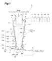
- a waste processing system 1 is a system for processing general and industrial waste and comprises a waste melting furnace 2, a granulation pit 5, a combustion chamber 6, a boiler 61, a cooling tower 62, a bag filter 63, a catalytic reaction tower 64, and a chimney 65.
- the waste melting furnace 2 thermally decomposes and gasifies combustible matters in the waste and melts ashes and noncombustible matters.
- gases generated from the waste are discharged from the upper part of the waste melting furnace 2, while melt generated from the waste are discharged from the lower part of the waste melting furnace 2.
- the granulation pit 5 granulates, cools, and collects the melt discharged from the waste melting furnace 2.
- the granulation pit 5 comprises a casing for retaining cooling water and a scraper conveyor (not depicted) for taking out the cooled products granulated and cooled within the casing.
- the combustion chamber 6 and boiler 61 are connected to the upper part of the waste melting furnace 2 through an exhaust duct, so as to collect thermal energy from exhaust gases of the waste melting furnace 2.
- the cooling tower 62, bag filter 63, and catalytic reaction tower 64 are connected to the downstream side of the boiler 61, so as to detoxify the exhaust gases.
- the chimney 65 discharges the detoxified exhaust gases.
- the waste melting furnace 2 is formed by a refractory material and the like, examples of which include bricks, SiC, and alumina.
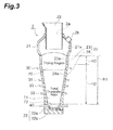
- the waste melting furnace 2 comprises a vertically extending cylindrical main part 20 centered at a vertical axis CL1, a gas induction part 21 joined to the upper side of the main part 20, and a melt reservoir part 22 joined to the lower side of the main part 20.
- the main part 20 forms a space for containing the waste and guides them from upside to downside.
- the gas induction part 21 collects gases generated from the waste within the main part 20 and guides the collected gases to the exhaust duct.
- the melt reservoir part 22 retains the melt generated from the waste within the main part 20.
- the main part 20 is constituted by a straight barrel part 23 having a fixed inner cross-sectional area and a taper part 24, joined to the lower side of the straight barrel part 23, having an inner cross-sectional area gradually decreasing to the downside.
- the straight barrel part 23 has a cylindrical inner face 23a, while the taper part 24 has an inner face 24a of an inverted truncated cone.
- the inner diameter of the upper end portion of the taper part 24 is equal to that of the straight barrel part 23.
- the height H2 of the taper part 24 is greater than the height H3 of the straight barrel part 23 (see Fig. 3 ). That is, the taper part 24 occupies the largest height in all of the parts constituting the main part 20. Therefore, the inner face 24a of the taper part 24 forms a greater angle of inclination ⁇ with a horizontal plane than in the case where the straight barrel part 23 occupies the largest height.
- the angle of inclination ⁇ is more than 75° but less than 90°. More preferably, it is at least 80° but less than 90°.
- the inner diameter and height of the main part 20 are determined according to volumes necessary for a drying region 70 and a thermal decomposition region 71 which will be explained later, for example.
- the volume necessary for the drying region 70 is a volume in which the total amount of moisture contained in the waste put into the waste melting furnace 2 per hour (i.e., input moisture amount) can be dried, assuming that the amount of moisture dried per hour is 50 to 150 kg/m 3 ⁇ h, for example.
- the volume necessary for the thermal decomposition region 71 is a volume in which the amount of carbon contained in the waste and coke put into the waste melting furnace 2 per hour can be gasified, assuming that the amount of gasification per hour is 50 to 150 kg/m 3 ⁇ h, for example.
- the melt reservoir part 22 has a cylindrical side wall part 22a centered at the axis CL1 and a bottom part 22b closing the lower end portion of the side wall part 22a.
- the upper end portion of the side wall part 22a is connected to the lower end portion of the taper part 24.
- the inner diameter of the side wall part 22a is equal to that of the lower end portion of the taper part 24.
- a tap hole 27 for discharging the melt retained in the melt reservoir part 22 is formed in the lower end portion of the side wall part 22a.
- the tap hole 27 is provided with an opening and closing mechanism (not depicted) through which the melt are discharged intermittently.
- Disposed on the outside of the tap hole 27 is a melt chute 28 extending obliquely downward from the side wall part 22a. The melt chute 28 sends the melt to the granulation pit 5.
- the gas induction part 21 exhibits a cylindrical form centered at the axis CL1.
- the lower end portion of the gas induction part 21 is connected to the upper end portion of the straight barrel part 23 of the main part 20.
- the inner diameter of the lower end portion of the gas induction part 21 is equal to that of the straight barrel part 23.
- the vertical middle portion of the gas induction part 21 bulges radially.
- the gas induction part 21 has an inner face 21 a which radially bulges as compared with the inner face 23a of the straight barrel part 23.
- the upper end portion of the gas induction part 21 is narrower than the lower end portion and constitutes an opening part 2a of the waste melting furnace 2.
- An inner cylinder 25 is inserted into the opening part 2a.
- the inner cylinder 25 has a cylindrical form centered at the axis CL1 and introduces the waste and a carbon-based combustible material into the waste melting furnace 2.
- the lower end portion of the inner cylinder 25 is located higher than that of the gas induction part 21.
- the upper portion of the gas induction part 21 is provided with an exhaust port 26.
- the exhaust port 26 discharges gases generated from the waste within the main part 20.
- the exhaust port 26 is connected to the combustion chamber 6 through the exhaust duct.
- the melt reservoir part 22 is provided with lower tuyeres 40 for feeding air enriched with oxygen (hereinafter referred to as "oxygen-enriched gas") into the furnace.
- oxygen-enriched gas air enriched with oxygen
- the oxygen enrichment is meant to enhance the oxygen concentration.
- the lower tuyeres 40 are arranged at a plurality of locations aligning circumferentially of the side wall part 22a. In a preferred example of their arrangement, the lower tuyeres 40 are arranged at eight locations circumferentially aligning at intervals of 45°. The leading end portion of each lower tuyere 40 may or may not project into the melt reservoir part 22.
- the taper part 24 is provided with upper tuyeres 30, 31, 32, 33 for feeding air into the furnace.
- the upper tuyeres 30, 31, 32, 33 align from the upside to downside.
- the number of stages of the vertically aligning upper tuyeres is not limited to 4 but may be less or more than 4.
- the respective sets of upper tuyeres 30, 31, 32, 33 are each arranged at a plurality of locations aligning circumferentially of the taper part 24. In a preferred example of their arrangement, each set of the upper tuyeres 30, 31, 32, 33 are arranged at four locations circumferentially aligning at intervals of 90°.
- the leading end portion of each of the upper tuyeres 30, 31, 32, 33 may or may not project into the taper part 24.
- a blower 42 is connected to the upper tuyeres 30, 31, 32, 33 and lower tuyeres 40. Flow paths from the blower 42 to the sets of upper tuyeres 30, 31, 32, 33 and lower tuyere 40 are provided with flow regulating valves 30a, 31a, 32a, 33a, 40a, respectively.
- An oxygen generator 41 for enriching air with oxygen is also connected to the flow path from the flow regulating valve 40a to the lower tuyeres 40.
- the waste melting furnace 2 is arranged with thermometers T1 to T5 for measuring in-furnace temperatures.
- the thermometer T1 is arranged in the upper portion of the gas introduction part 21.
- the thermometer T5 is embedded in the refractory material constituting the bottom part 22b of the melt reservoir part 22.
- the thermometers T2, T3, T4 align from the upside to downside between the thermometers T1, T5.
- the waste melting furnace 2 is also arranged with a plurality of pressure gauges for measuring in-furnace pressures.
- the pressure gauge P1 is arranged in the upper portion of the gas induction part 21.
- the pressure gauges P2, P3, P4 are arranged in the upper, middle, and lower portions of the taper part 24, respectively.
- a carbon-based combustible material is introduced into the furnace 2 through the inner cylinder 25.
- An example of the carbon-based combustible material is coke. Coke may wholly or partly be replaced by carbides of biomass such as wood.
- the coke accumulated on the bottom part 22b in the waste melting furnace 2 is ignited by a burner (not depicted) or the like. This forms a so-called coke bed 81 on the bottom part in the furnace.
- a mixture of coke and waste is introduced into the waste melting furnace 2 through the inner cylinder 25 and fills the main part 20.
- the kind of the waste is not limited in particular but may be any of general and industrial waste. This can process shredder dust (ASR), dug-up refuse, burned ash, and the like either singly or in mixtures with or without combustible refuse. Dry-distilled waste may also be put in. Limestone and the like as an alkalinity adjuster may be added to the waste in addition to coke.
- the oxygen-enriched gas is fed into the furnace through the lower tuyeres 40.
- the blast pressure of the oxygen-enriched gas it is set within the range of 5 to 25 kPa.
- Fuel gases such as LNG may be mixed with the oxygen-enriched gas fed into the furnace through the lower tuyeres 40.
- An air is fed into the furnace through the upper tuyeres 30, 31, 32, 33.
- the blast pressure of the air it is set within the range of 5 to 25 kPa.
- the oxygen-enriched gas fed from the lower tuyeres 40 keeps coke burning, thereby producing a high-temperature in-furnace gas, which ascends.
- the air fed from the upper tuyeres 30, 31, 32, 33 partly burns the waste in the taper part 24, thereby producing a high-temperature in-furnace gas, which ascends.
- the waste is guided to the main part 20 and descends against upward flows of the in-furnace gases. In this process, heat exchange occurs between the waste and the in-furnace gases, thereby promoting the drying and thermal decomposition of the waste. Gases produced by the thermal decomposition of the waste concentrate in the gas induction part 21 and are guided to the upside, so as to be discharged through the exhaust port 26. The discharged gases are sent to the combustion chamber 6 through the exhaust duct.
- the char layer 82 functions as a ventilation-resistance layer and adjusts flows of the oxygen-enriched gas fed from the lower tuyeres 40. This prevents local blowout of the oxygen-enriched air fed from the lower tuyeres 40.
- the combustible dry-distilled product (fixed carbon) in the thermal decomposition residue is burned with coke.
- the combustion gas of coke and combustible dry-distilled product attains the highest temperature in a region near the upper end of the coke bed 81.
- the ashes and noncombustible matters melt in this region.
- the melt enters the melt reservoir part 22 through interstices of the coke bed, so as to be retained.
- Thus retained melt is intermittently taken out from the tap hole 27.
- the melt taken out from the tap hole 27 is granulated and cooled in the granulation pit 5, so as to be collected as slag and metals. Subsequently, the furnace is refilled with the mixture of coke and waste, and the waste melting processing is continued.
- the drying region 70 is formed in the upper portion within the waste melting furnace 2.
- the drying region 70 mainly performs the drying and preheating of the waste.
- the thermal decomposition region 71 is formed under the drying region 70.
- the thermal decomposition region 71 1. mainly performs the thermal decomposition and gasification of combustible components in the dried waste.
- a melting region 72 is formed under the thermal decomposition region 71.
- the melting region 72 mainly performs the melting of ashes and noncombustible matters (see Fig. 3 ).
- the upper end portion of the taper part 24 is higher than in the case where the straight barrel part 23 occupies the largest height, thus reaching the drying region 70, whereby the boundary between the drying region 70 and thermal decomposition region 71 is located in the taper part 24.
- the upper tuyeres 30 arranged at the uppermost stage are located in the drying region 70.
- the upper tuyeres 30 are located closer to the lower end portion of the drying region 70 between the lower end portion of the drying region 70 and the upper end portion of the taper part 24.
- a greater gap is formed between waste pieces in the drying region 70 than in the thermal decomposition region 71, whereby the waste in the drying region 70 is easier to move than that in the thermal decomposition region 71. Therefore, if the upper tuyeres 30 of the drying region 70 yield a too much amount of blast, it may foster the formation of blowout paths for the in-furnace gases. It is therefore preferable for the amount of blast from the upper tuyeres 30 to be 50 Nm 3 /h or less per location. It is not always necessary for the drying region 70 to be provided with the upper tuyeres 30. Two or more stages of the four-stage upper tuyeres 30, 31, 32, 33 may be arranged within the drying region 70.
- thermometers T1 to T5 are arranged within the waste melting furnace 2 from its upper portion to lower portion. The extent of the drying region 70, thermal decomposition region 71, and melting region 72 can roughly be grasped according to the respective temperatures measured by the thermometers.
- the position of the boundary between the drying region 70 and thermal decomposition region 71 can also be grasped according to in-furnace differential pressures.
- the waste reduces its volume by losing the moisture upon drying.
- the waste forms carbide particles by being thermally decomposed, so as to further reduce its volume, thereby thickening. Therefore, a difference of about 0.5 kPa/m, for example, exists between the differential pressure in the drying region and that in the thermal decomposition region.
- the differential pressure is the amount of rise in pressure caused by a descent of 1 m.
- grasping a part where the differential pressure rises by about 0.5 kPa/m as compared with that in the upper region can roughly figure out the boundary between the drying region 70 and the thermal decomposition region 71.
- the respective differential pressures in the individual parts within the furnace can roughly be grasped by the pressure gauges P1 to P4 arranged within the furnace. For example, when the differential pressure near the middle pressure gauge P3 is higher than that in the upper region by about 0.5 kPa/m, the vicinity of the middle pressure gauge P3 is grasped as the boundary between the drying region 70 and the thermal decomposition region 71.
- the thermal decomposition region 71 of the waste is a region located lower than the part where the differential pressure has completely risen to 0.5 kPa/m or more within the drying region 70.
- the differential pressure means the differential pressure at the time when the operation of the furnace is relatively stable, while excluding the differential pressure at the time when the gas blowout and the like occur.
- the taper part 24 occupies the largest height in all of the parts constituting the main part 20. Therefore, the inner face 24a of the taper part 24 forms a greater angle of inclination with the horizontal plane than in the case where the non-tapered straight barrel part 23 occupies the largest height. As a consequence, the waste in the vicinity of the inner face 24a of the taper part 24 is guided smoothly to the downside. Further, the inner face 24a of the taper part 24 tilts moderately with respect to the inner face 23a of the straight barrel part 23, thereby making it hard for the waste to stop at the upper end portion of the taper part 24.
- the upper end portion of the taper part 24 is located on the upper side of the main part 20.
- the waste reduces its volume by being dried and thermally decomposed as it descends through the main part 20.
- the volume reduction also proceeds on the upper side of the main part 20.
- the cross-sectional area of the main part 20 becomes smaller from the upper side to downside in conformity to the volume reduction also proceeding on the upper side of the main part 20. This inhibits spaces from being formed and prevents the gas blowout from occurring.
- the fact that the inner volume of the main part 20 is smaller than that in the case where the straight barrel part 23 occupies the largest height does not adversely affect the efficiency in processing the waste. This is because the efficiency in heat exchange between the waste and the in-furnace gases improves as mentioned above, so that the waste reduces its volume efficiently.
- the inner face 24a of the taper part 24 forms an angle of inclination greater than 75° but less than 90° with the horizontal plane. This more securely prevents the waste from stagnating. Hence, the efficiency in heat exchange between the waste and the in-furnace gas can further be improved.
- the boundary between the drying region 70 and the thermal decomposition region 71 is located in the taper part 24.
- the upper end portion of the taper part 24 is located in the drying region 70.
- the above-mentioned volume reduction of the waste also proceeds within the drying region 70.
- the cross-sectional area of the main part 20 becomes smaller from within the drying region 70 to the downside in conformity to the volume reduction also proceeding within the drying region 70. This can more securely inhibit spaces from occurring.
- the upper tuyeres 30 are located in the drying region 70. This further promotes the drying of the waste in the drying region 70. Since the upper end portion of the taper part 24 is located in the drying region 70 as mentioned above, the waste in the drying region 70 descends along the taper part 24. The waste further reduces its volume as the drying thereof is promoted, whereby the burden descent along the taper part 24 is more smoothened. The waste having reduced its volume by promoting the drying thereof is accumulated at the center by the taper part 24, whereby spaces are inhibited from being formed.
- the fact that the upper end portion of the taper part 24 is located in the drying region 70 cooperates with the fact that the drying region 70 is provided with the upper tuyeres 30, thereby making it possible to promote the drying of the waste while inhibiting spaces from being formed.
- the upper tuyeres 30 are located closer to the lower end portion of the drying region 70 between the lower end portion of the drying region 70 and the upper end portion of the taper part 24. This can separate the upper tuyeres 30 located in the drying region 70 from the boundary between the straight barrel part 23 and the taper part 24 and more securely inhibit spaces from occurring.
- the waste melting furnace 2 inhibits thermal decomposition residues from adhering and thus can dramatically reduce the workload at the time of maintenance of the waste melting furnace 2. Since spaces are restrained from occurring, the waste melting furnace 2 can be operated stably. If a space occurs and then grows, the in-furnace differential pressure will decrease. When the growing space is filled by a load shift, the in-furnace differential pressure rises drastically. Restraining spaces from occurring suppresses such fluctuations in the in-furnace differential pressure, thereby enabling the waste melting furnace to operate stably.
- the inner diameter of the thermal decomposition region 71 is smaller than that in the conventional furnace as compared with the case where the straight barrel part 23 occupies the largest height.
- the char layer can accordingly increase its thickness, thereby securing a sufficient in-furnace differential pressure. This also contributes to stabilizing the operation of the waste melting furnace 2.
- the present invention is not necessarily limited to the above-mentioned embodiment but may be modified in various ways within the scope not deviating from the gist thereof.
- the main part 20 may be constituted by the taper part 24 alone without the straight barrel part 23. That is, the taper part 24 may occupy the total height H1 of the main part 20.
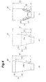
- Example 1 a waste melting furnace 2A schematically illustrated in Fig. 4(a) was prepared.
- the waste melting furnace 2A corresponds to the waste melting furnace 2 of the above-mentioned embodiment.
- the ratio of the height H2 of the taper part 24 with respect to the total height H1 of the main part 20 is 95%.
- the inner face 24a of the taper part 24 forms an angle of inclination ⁇ of 80° with the horizontal plane.
- the above-mentioned thermometers T2 are disposed at four locations which align circumferentially at intervals of 90°.
- Example 2 a waste melting furnace 2B schematically illustrated in Fig. 4(b) was prepared.
- the waste melting furnace 2B corresponds to the waste melting furnace 2 of the above-mentioned embodiment.
- the ratio of the height H2 of the taper part 24 with respect to the total height H1 of the main part 20 is 50%.
- the inner face 24a of the taper part 24 forms an angle of inclination ⁇ of 75° with the horizontal plane.
- the inner diameter of the straight barrel part 23, the inner diameter of the lower end portion of the taper part 24, and the total height H1 of the main part 20 in the waste melting furnace 2B are equal to those in the waste melting furnace 2A.
- a waste melting furnace 2C schematically illustrated in Fig. 4(c) was prepared.
- the waste melting furnace 2C differs from the above-mentioned waste melting furnace 2 in the following points.
- the straight barrel part 23 occupies the largest height in all of the parts constituting the main part 20.
- the ratio of the height H2 of the taper part 24 with respect to the total height H1 of the main part 20 is 35%.
- the upper tuyeres 30, 31, 32, 33 the uppermost ones 30 are omitted. All of the upper tuyeres 31, 32, 33 are located in the thermal decomposition region 71.
- the inner face 24a of the taper part 24 forms an angle of inclination 0 of 70° with the horizontal plane.
- the inner diameter of the straight barrel part 23, the inner diameter of the lower end portion of the taper part 24, and the total height H1 of the main part 20 in the waste melting furnace 2C are equal to those in the waste melting furnace 2A.
- the above-mentioned thermometers T2 are disposed at four locations which align circumferentially at intervals of 90° also in the waste melting furnace 2C.
- the waste melting furnaces 2A, 2B, 2C of Examples 1 and 2 and Comparative Example 1 were operated at the same period of time, and their in-furnace differential pressures were measured. As for the furnaces 2A, 2C of Example 1 and Comparative Example 1, their furnace-top gas temperature and middle-furnace gas temperature were measured. For evaluating only the effects of forms of the main part 20 while using Comparative Example 1 having no upper tuyeres 30 as a subject for comparison, no air was fed from the upper tuyeres 30 in Examples 1 and 2.
- the in-furnace differential pressure in this test example is the difference between the value detected by the pressure gauge P4 disposed in the lower portion of the taper part 24 and the value detected by the pressure gauge P1 disposed in the upper portion of the gas induction part 21.
- the furnace-top gas temperature is the value detected by the thermometer T1 disposed in the upper portion of the gas induction part 21.
- the middle-furnace gas temperature is the value measured by the thermometer T2.
- Fig. 5 is a graph illustrating daily shifts in the in-furnace differential pressure.
- Comparative Example 1 as a polygonal line L1 in Fig. 5 indicates, the in-furnace differential pressure was low during the period from the first day to the third day, thereby falling below the lower limit LL of a range suitable for operating the furnace. It is speculated from these results that the gas blowout occurred during the period from the first day to the third day in the waste melting furnace 2C, thereby lowering the in-furnace differential pressure.
- the gas blowout seems to be caused by the waste stagnating in the vicinity of the inner face 24a of the taper part 24 in the waste melting furnace 2C (see hatched parts in Fig. 4(c) ).
- the stagnating waste if any, may locally be thermally decomposed by the air from the upper tuyeres 31, 32, 33, for example, so as to generate spaces, which may grow, thereby forming flow paths for the in-furnace gases (this phenomenon is likely to occur in particular in the vicinity of the boundary between the inner face 23a of the straight barrel part 23 and the inner face 24a of the taper part 24).
- Fig. 6 is a graph illustrating daily shifts in the furnace-top gas temperature.
- the furnace-top gas temperature in Comparative Example 1 is high during the period from the first day to the third day and differs much from that on the fourth day and thereafter.
- the temperature during the period from the first day to the third day exceeds the upper limit ML of a range desirable for operating the furnace. It is seen from these results that the gas blowout occurred during the period from the first day to the third day in Comparative Example 1, thereby raising the furnace-top gas temperature.
- Example 1 By contrast, as a polygonal line L5 in Fig. 6 indicates, the furnace-top gas temperature in Example 1 was lower than the upper limit ML of the range desirable for operating the furnace, while its width of daily shift was small. It is speculated from these results that the gas blowout is restrained from occurring in Example 1.
- Fig. 7 illustrates results of measurement of the middle-furnace gas temperature.
- Fig. 7 is a set of graphs illustrating shifts in the middle-furnace gas temperature with time. As Fig. 7(a) indicates, a large temperature fluctuation with time was seen in each of the four thermometers T2 in Comparative Example 1. Time slots when the temperature fluctuated vary among the thermometers. It is speculated from these results that the gas blowouts occurred one after another at different locations in different time slots within the furnace in Comparative Example 1.
- the present invention can restrain the gas blowout from occurring.
- the ratio of the height H2 of the taper part 24 with respect to the total height H1 of the main part 20 is 50% or more in Example 2, it is substantially seen that the gas blowout can be restrained from occurring if the condition that the taper part occupies the largest height in all of the parts constituting the main part 20 is satisfied.
- the waste melting furnaces 2A, 2C of Example 1 and Comparative Example 1 were operated for about one week at the same period of time, and their coke ratios were compared with each other.
- no air was fed from the upper tuyeres 30 in Examples 1 and 2.
- Fig. 8 is a chart illustrating results of measurement of the amount of waste processed, coke ratio, in-furnace differential pressure, and furnace-top gas temperature.
- the coke ratio, in-furnace differential pressure, and furnace-top gas temperature are indicated by differences from the results of measurement of Comparative Example 1 serving as a reference.
- the coke ratio (kg/TR) is a value obtained by dividing the amount (kg) of coke put into the melting furnace by the total amount (t) of the waste processed in the melting furnace.
- the coke ratio was lower in Example 1 by about 12.7 kg/TR than in Comparative Example 1 in a short-term test of about one week. It is seen from these results that the present invention can reduce the consumption of carbon-based combustible materials.
- the furnace-top gas temperature in Example 1 is lower by about 100°C than that in Comparative Example 1.
- the in-furnace differential pressure in Example 1 is higher by about 1.5 kPa than that in Comparative Example 1. It is speculated from these results that the stagnation of waste and the occurrence of gas blowout are suppressed in the waste melting furnace 2A. This seems to contribute greatly to cutting down the consumption of carbon-based combustible materials.
- the waste melting furnaces 2A, 2C of Example 1 and Comparative Example 1 were operated at the same period of time, and their drying capacities were compared with each other.
- As parameters related to the drying capacities their in-furnace gas flow rates (superficial velocities), in-furnace differential pressures, coke ratios, in-furnace heat exchange temperatures, moisture drying capacities per volume, and heat transfer efficiencies were measured during the operation and compared.
- This evaluation is aimed at verifying effects obtained when the lower end portion of the drying region 70 is located in the taper part 24 while the drying region 70 is provided with the upper tuyeres 30. Therefore, the air was fed from the upper tuyeres 30 in Example 1.
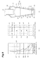
- Fig. 9(a) is a graph illustrating in-furnace gas flow rate (superficial velocity) distributions in the furnace height direction.
- Curves L6, L7 illustrate in-furnace gas flow rates in Example 1 and Comparative Example 1, respectively.
- Reference lines b1, b2, b3, b4 indicate where the upper tuyeres 30, 31, 32, 33 are placed, respectively.
- Fig. 9(b) is a chart plotting an in-furnace differential pressure distribution in the furnace height direction.
- Reference lines a1, a2, a3, a4, a5 indicate where pressure gauges used for measuring the in-furnace differential pressures are placed. The pressure gauges used here differ from the above-mentioned pressure gauges P1, P2, P3, P4.
- Dots F1, F2, F3, F4 indicate the differential pressure between the reference lines a2, a1, the differential pressure between the reference lines a3, a2, the differential pressure between the reference lines a4, a3, and the differential pressure between the reference lines a5, a4, respectively.
- Figs. 9(a) and 9(b) are represented with their ordinates indicating the furnace height, while the scale of each ordinate is in conformity to the height in the sectional view of the furnace illustrated in Fig. 9(c) .
- Example 1 improves the efficiency in heat exchange between the in-furnace gas and the waste and enhances the drying capacity. Also, as mentioned above, Example 1 inhibits the gas blowout from occurring and stabilizes the in-furnace gas flow. Therefore, the fact that the in-furnace gas flow rate becomes higher and the fact that the in-furnace gas flow is stabilized are assumed to cooperate with each other, so as to further improve the efficiency in heat exchange between the in-furnace gas and the waste.
- Example 1 In Comparative Example 1, the gas blowout often occurred during the operation, thereby raising the furnace-top gas temperature, thus forcing to stop blasting from the upper tuyeres 31. The result also appears in the flow rate data in Fig. 9 . By contrast, Example 1 restrained the gas blowout from occurring, thus enabling stable and steady blasting from the upper tuyeres 31.
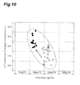
- Fig. 10 is a chart plotting results of measurement of in-furnace heat exchange temperature (°C) and coke ratio (kg/TR).
- Example 1 exhibited higher heat exchange temperature and lower coke ratio than Comparative Example 1. That is, Example 1 is seen to promote the drying of the waste as compared with Comparative Example 1.
- Fig. 11 is a chart plotting results of measurement of moisture drying capacity per volume (Mcal/(m 3 ⁇ h)) and coke ratio (kg/TR).
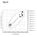
- Fig. 12 is a chart plotting results of measurement of heat transfer efficiency (Mcal/(m3 ⁇ h ⁇ °C)) and in-furnace gas flow rate (superficial velocity) (Bm/s).
- heat transfer efficiency heat transfer area ⁇ heat transfer coefficient .
- the in-furnace gas flow rate indicates the flow rate at the height of the upper tuyeres 30.
- Example 1 is seen to have a drying capacity which is about 2.5 times that of Comparative Example 1.
- the 2.5-fold improvement in drying capacity is caused by about a 1.7-fold improvement due to the stabilization of the in-furnace gas flow and about a 1.5-fold improvement due to the increased in-furnace gas flow rate.
- Fig. 13 is a chart plotting results of measurement of gas blowout occurrence time and coke ratio.
- black circles indicate the results of measurement in the case where the air was fed from the upper tuyeres 30, while white triangles indicate the results of measurement in the case where no air was fed from the upper tuyeres 30.
- Fig. 13 illustrates, when no air was blown in from the upper tuyeres 30, the gas blowout time fluctuated a lot, and there were instances where the blowout occurred for a long period of time.
- the white triangles also indicate a tendency of the coke ratio to increase under the influence of the long-term blowout when the latter occurs.
- the present invention can be utilized for processing general and industrial waste.
Landscapes
- Engineering & Computer Science (AREA)
- Mechanical Engineering (AREA)
- General Engineering & Computer Science (AREA)
- Gasification And Melting Of Waste (AREA)
- Processing Of Solid Wastes (AREA)
Priority Applications (1)
| Application Number | Priority Date | Filing Date | Title |
|---|---|---|---|
| PL13830075T PL2940386T3 (pl) | 2012-12-25 | 2013-07-26 | Piec do topienia odpadów |
Applications Claiming Priority (2)
| Application Number | Priority Date | Filing Date | Title |
|---|---|---|---|
| JP2012281343A JP5283780B1 (ja) | 2012-12-25 | 2012-12-25 | 廃棄物溶融炉 |
| PCT/JP2013/070334 WO2014103417A1 (fr) | 2012-12-25 | 2013-07-26 | Four de fusion de déchets |
Publications (3)
| Publication Number | Publication Date |
|---|---|
| EP2940386A1 true EP2940386A1 (fr) | 2015-11-04 |
| EP2940386A4 EP2940386A4 (fr) | 2016-08-24 |
| EP2940386B1 EP2940386B1 (fr) | 2019-09-04 |
Family
ID=49274015
Family Applications (1)
| Application Number | Title | Priority Date | Filing Date |
|---|---|---|---|
| EP13830075.1A Active EP2940386B1 (fr) | 2012-12-25 | 2013-07-26 | Four de fusion de déchets |
Country Status (8)
| Country | Link |
|---|---|
| EP (1) | EP2940386B1 (fr) |
| JP (1) | JP5283780B1 (fr) |
| KR (1) | KR101921225B1 (fr) |
| CN (1) | CN104053949B (fr) |
| BR (1) | BR112014006698B8 (fr) |
| ES (1) | ES2748138T3 (fr) |
| PL (1) | PL2940386T3 (fr) |
| WO (1) | WO2014103417A1 (fr) |
Families Citing this family (6)
| Publication number | Priority date | Publication date | Assignee | Title |
|---|---|---|---|---|
| JP6299466B2 (ja) * | 2014-06-17 | 2018-03-28 | Jfeエンジニアリング株式会社 | 廃棄物ガス化溶融装置及び廃棄物ガス化溶融方法 |
| CN105605581B (zh) * | 2016-03-09 | 2017-11-28 | 中冶华天工程技术有限公司 | 竖式垃圾气化熔融炉 |
| CN106642139A (zh) * | 2017-02-20 | 2017-05-10 | 长沙超梵环境科技有限公司 | 生活垃圾热解气化飞灰直接熔融装置及其使用方法 |
| CN108330282A (zh) * | 2018-03-08 | 2018-07-27 | 扬州晨光特种设备有限公司 | 危险废弃物熔融-冶金一体化的处理方法 |
| CN108775585B (zh) * | 2018-07-04 | 2020-05-12 | 加拿大艾浦莱斯有限公司 | 一种废弃物高温空气/水蒸气气化燃烧熔融系统 |
| CN112197588B (zh) * | 2020-10-30 | 2023-04-07 | 唐海燕 | 一种带碾压净化处理机构的环保型垃圾回收装置 |
Family Cites Families (16)
| Publication number | Priority date | Publication date | Assignee | Title |
|---|---|---|---|---|
| JPS5316633B2 (fr) * | 1974-01-23 | 1978-06-02 | ||
| JPS6011766B2 (ja) * | 1978-12-25 | 1985-03-28 | 新日本製鐵株式会社 | 廃棄物の溶融式熱分解炉における燃焼支持ガス吹込方法 |
| US4346661A (en) * | 1980-03-20 | 1982-08-31 | Osaka Gas Kabushiki Kaisha | Furnace for treating industrial wastes |
| JPS5838694B2 (ja) * | 1980-04-28 | 1983-08-24 | 大阪瓦斯株式会社 | 産業廃棄物処理炉 |
| JP2515169B2 (ja) * | 1990-07-25 | 1996-07-10 | 善元 浮田 | ゴミ焼却炉 |
| JP2723010B2 (ja) * | 1993-10-29 | 1998-03-09 | 日本鋼管株式会社 | 収束衝撃波による廃棄物処理装置 |
| JP3542831B2 (ja) * | 1994-09-27 | 2004-07-14 | 新日本製鐵株式会社 | 廃棄物の溶融炉 |
| JP3742441B2 (ja) * | 1994-09-27 | 2006-02-01 | 新日本製鐵株式会社 | シャフト炉方式の廃棄物の溶融炉における燃焼温度調整方法 |
| JPH09112852A (ja) * | 1995-10-17 | 1997-05-02 | Nippon Steel Corp | 廃棄物の処理装置および処理方法 |
| JPH09329313A (ja) * | 1996-06-07 | 1997-12-22 | Kubota Corp | 廃棄物ガス化溶融炉の操炉方法 |
| JP2000291919A (ja) * | 1999-04-07 | 2000-10-20 | Nippon Steel Corp | シャフト炉式熱分解溶融炉及び熱分解溶融方法 |
| JP3445958B2 (ja) * | 2000-04-26 | 2003-09-16 | 株式会社川崎技研 | シャフト型熱分解溶融炉 |
| JP2002130632A (ja) * | 2000-10-27 | 2002-05-09 | Kawasaki Heavy Ind Ltd | 廃棄物ガス化溶融炉とその操業方法 |
| JP3969016B2 (ja) * | 2001-05-31 | 2007-08-29 | Jfeエンジニアリング株式会社 | 廃棄物溶融炉 |
| JP2011012901A (ja) * | 2009-07-02 | 2011-01-20 | Nippon Steel Engineering Co Ltd | 廃棄物溶融炉 |
| JP5490488B2 (ja) * | 2009-10-21 | 2014-05-14 | 新日鉄住金エンジニアリング株式会社 | 廃棄物溶融処理方法 |
-
2012
- 2012-12-25 JP JP2012281343A patent/JP5283780B1/ja active Active
-
2013
- 2013-07-26 CN CN201380003838.XA patent/CN104053949B/zh active Active
- 2013-07-26 BR BR112014006698A patent/BR112014006698B8/pt active IP Right Grant
- 2013-07-26 EP EP13830075.1A patent/EP2940386B1/fr active Active
- 2013-07-26 WO PCT/JP2013/070334 patent/WO2014103417A1/fr active Application Filing
- 2013-07-26 PL PL13830075T patent/PL2940386T3/pl unknown
- 2013-07-26 ES ES13830075T patent/ES2748138T3/es active Active
- 2013-07-26 KR KR1020147028431A patent/KR101921225B1/ko active IP Right Grant
Also Published As
| Publication number | Publication date |
|---|---|
| EP2940386B1 (fr) | 2019-09-04 |
| CN104053949A (zh) | 2014-09-17 |
| KR101921225B1 (ko) | 2018-11-22 |
| WO2014103417A1 (fr) | 2014-07-03 |
| ES2748138T3 (es) | 2020-03-13 |
| KR20150099684A (ko) | 2015-09-01 |
| JP2014126227A (ja) | 2014-07-07 |
| EP2940386A4 (fr) | 2016-08-24 |
| JP5283780B1 (ja) | 2013-09-04 |
| BR112014006698A2 (pt) | 2017-04-11 |
| BR112014006698B1 (pt) | 2021-12-07 |
| PL2940386T3 (pl) | 2020-02-28 |
| CN104053949B (zh) | 2017-05-24 |
| BR112014006698B8 (pt) | 2022-11-08 |
Similar Documents
| Publication | Publication Date | Title |
|---|---|---|
| EP2940386B1 (fr) | Four de fusion de déchets | |
| JP5120823B1 (ja) | 廃棄物ガス化溶融炉 | |
| DK2631222T3 (en) | WASTE TREATMENT DEVICES | |
| JP5744904B2 (ja) | 流動床炉及び廃棄物の処理方法 | |
| EP2765177B1 (fr) | Système de gazéification | |
| JP5166213B2 (ja) | 溶融炉 | |
| JP5154094B2 (ja) | ガス化溶融システムの燃焼制御方法及び該システム | |
| JP5426119B2 (ja) | ガス化溶融システムの燃焼制御方法及び該システム | |
| JP2006207911A (ja) | 廃棄物溶融炉の操業方法 | |
| JP4918834B2 (ja) | 廃棄物溶融炉および廃棄物溶融炉の操業方法 | |
| JP4126317B2 (ja) | ガス化溶融システムの運転制御方法及び該システム | |
| JP5086177B2 (ja) | ガス化溶融設備及びガス化溶融設備の溶融炉燃焼用空気供給方法 | |
| JP2015075246A (ja) | 廃棄物ガス化溶融炉及びその運転方法 | |
| JP5855785B1 (ja) | 廃棄物ガス化溶融炉の運転方法 | |
| JP6223104B2 (ja) | 廃棄物ガス化溶融炉及びその運転方法 | |
| JP5855786B1 (ja) | 廃棄物ガス化溶融炉の運転方法 | |
| JP6299467B2 (ja) | 廃棄物ガス化溶融装置及び廃棄物ガス化溶融方法 | |
| JP6299466B2 (ja) | 廃棄物ガス化溶融装置及び廃棄物ガス化溶融方法 | |
| JP5909583B1 (ja) | 廃棄物ガス化溶融炉の運転方法 | |
| JP5886144B2 (ja) | 廃棄物処理装置 | |
| JP5909584B1 (ja) | 廃棄物ガス化溶融炉の運転方法 | |
| JP2014001915A (ja) | 廃棄物ガス化溶融炉における送風制御方法および廃棄物ガス化溶融炉 | |
| JP4742686B2 (ja) | 高炉への合成樹脂材の吹き込み方法 | |
| JP5783078B2 (ja) | 廃棄物ガス化溶融炉のクリンカの破壊・発生抑制装置 | |
| JP2019007718A (ja) | 廃棄物溶融炉及びその運転方法 |
Legal Events
| Date | Code | Title | Description |
|---|---|---|---|
| PUAI | Public reference made under article 153(3) epc to a published international application that has entered the european phase |
Free format text: ORIGINAL CODE: 0009012 |
|
| 17P | Request for examination filed |
Effective date: 20150723 |
|
| AK | Designated contracting states |
Kind code of ref document: A1 Designated state(s): AL AT BE BG CH CY CZ DE DK EE ES FI FR GB GR HR HU IE IS IT LI LT LU LV MC MK MT NL NO PL PT RO RS SE SI SK SM TR |
|
| AX | Request for extension of the european patent |
Extension state: BA ME |
|
| DAX | Request for extension of the european patent (deleted) | ||
| A4 | Supplementary search report drawn up and despatched |
Effective date: 20160726 |
|
| RIC1 | Information provided on ipc code assigned before grant |
Ipc: F27B 1/10 20060101ALI20160720BHEP Ipc: F27B 1/16 20060101ALI20160720BHEP Ipc: F27B 17/00 20060101ALI20160720BHEP Ipc: F23G 5/027 20060101ALI20160720BHEP Ipc: F27B 1/00 20060101ALI20160720BHEP Ipc: F23G 5/24 20060101AFI20160720BHEP Ipc: F23G 5/00 20060101ALI20160720BHEP |
|
| STAA | Information on the status of an ep patent application or granted ep patent |
Free format text: STATUS: EXAMINATION IS IN PROGRESS |
|
| 17Q | First examination report despatched |
Effective date: 20170630 |
|
| GRAP | Despatch of communication of intention to grant a patent |
Free format text: ORIGINAL CODE: EPIDOSNIGR1 |
|
| STAA | Information on the status of an ep patent application or granted ep patent |
Free format text: STATUS: GRANT OF PATENT IS INTENDED |
|
| INTG | Intention to grant announced |
Effective date: 20190213 |
|
| GRAS | Grant fee paid |
Free format text: ORIGINAL CODE: EPIDOSNIGR3 |
|
| RAP1 | Party data changed (applicant data changed or rights of an application transferred) |
Owner name: NIPPON STEEL ENVIRONMENTAL PLANT SOLUTIONS CORPORA Owner name: NIPPON STEEL ENGINEERING CO., LTD. |
|
| GRAA | (expected) grant |
Free format text: ORIGINAL CODE: 0009210 |
|
| STAA | Information on the status of an ep patent application or granted ep patent |
Free format text: STATUS: THE PATENT HAS BEEN GRANTED |
|
| AK | Designated contracting states |
Kind code of ref document: B1 Designated state(s): AL AT BE BG CH CY CZ DE DK EE ES FI FR GB GR HR HU IE IS IT LI LT LU LV MC MK MT NL NO PL PT RO RS SE SI SK SM TR |
|
| REG | Reference to a national code |
Ref country code: GB Ref legal event code: FG4D |
|
| REG | Reference to a national code |
Ref country code: CH Ref legal event code: EP Ref country code: CH Ref legal event code: NV Representative=s name: BOVARD AG PATENT- UND MARKENANWAELTE, CH |
|
| REG | Reference to a national code |
Ref country code: AT Ref legal event code: REF Ref document number: 1175863 Country of ref document: AT Kind code of ref document: T Effective date: 20190915 |
|
| REG | Reference to a national code |
Ref country code: SE Ref legal event code: TRGR |
|
| REG | Reference to a national code |
Ref country code: DE Ref legal event code: R096 Ref document number: 602013060156 Country of ref document: DE |
|
| REG | Reference to a national code |
Ref country code: IE Ref legal event code: FG4D |
|
| REG | Reference to a national code |
Ref country code: NL Ref legal event code: MP Effective date: 20190904 |
|
| REG | Reference to a national code |
Ref country code: LT Ref legal event code: MG4D |
|
| PG25 | Lapsed in a contracting state [announced via postgrant information from national office to epo] |
Ref country code: LT Free format text: LAPSE BECAUSE OF FAILURE TO SUBMIT A TRANSLATION OF THE DESCRIPTION OR TO PAY THE FEE WITHIN THE PRESCRIBED TIME-LIMIT Effective date: 20190904 Ref country code: FI Free format text: LAPSE BECAUSE OF FAILURE TO SUBMIT A TRANSLATION OF THE DESCRIPTION OR TO PAY THE FEE WITHIN THE PRESCRIBED TIME-LIMIT Effective date: 20190904 Ref country code: HR Free format text: LAPSE BECAUSE OF FAILURE TO SUBMIT A TRANSLATION OF THE DESCRIPTION OR TO PAY THE FEE WITHIN THE PRESCRIBED TIME-LIMIT Effective date: 20190904 Ref country code: BG Free format text: LAPSE BECAUSE OF FAILURE TO SUBMIT A TRANSLATION OF THE DESCRIPTION OR TO PAY THE FEE WITHIN THE PRESCRIBED TIME-LIMIT Effective date: 20191204 |
|
| REG | Reference to a national code |
Ref country code: NO Ref legal event code: T2 Effective date: 20190904 |
|
| PG25 | Lapsed in a contracting state [announced via postgrant information from national office to epo] |
Ref country code: AL Free format text: LAPSE BECAUSE OF FAILURE TO SUBMIT A TRANSLATION OF THE DESCRIPTION OR TO PAY THE FEE WITHIN THE PRESCRIBED TIME-LIMIT Effective date: 20190904 Ref country code: LV Free format text: LAPSE BECAUSE OF FAILURE TO SUBMIT A TRANSLATION OF THE DESCRIPTION OR TO PAY THE FEE WITHIN THE PRESCRIBED TIME-LIMIT Effective date: 20190904 Ref country code: GR Free format text: LAPSE BECAUSE OF FAILURE TO SUBMIT A TRANSLATION OF THE DESCRIPTION OR TO PAY THE FEE WITHIN THE PRESCRIBED TIME-LIMIT Effective date: 20191205 Ref country code: RS Free format text: LAPSE BECAUSE OF FAILURE TO SUBMIT A TRANSLATION OF THE DESCRIPTION OR TO PAY THE FEE WITHIN THE PRESCRIBED TIME-LIMIT Effective date: 20190904 |
|
| REG | Reference to a national code |
Ref country code: ES Ref legal event code: FG2A Ref document number: 2748138 Country of ref document: ES Kind code of ref document: T3 Effective date: 20200313 |
|
| PG25 | Lapsed in a contracting state [announced via postgrant information from national office to epo] |
Ref country code: NL Free format text: LAPSE BECAUSE OF FAILURE TO SUBMIT A TRANSLATION OF THE DESCRIPTION OR TO PAY THE FEE WITHIN THE PRESCRIBED TIME-LIMIT Effective date: 20190904 Ref country code: EE Free format text: LAPSE BECAUSE OF FAILURE TO SUBMIT A TRANSLATION OF THE DESCRIPTION OR TO PAY THE FEE WITHIN THE PRESCRIBED TIME-LIMIT Effective date: 20190904 Ref country code: RO Free format text: LAPSE BECAUSE OF FAILURE TO SUBMIT A TRANSLATION OF THE DESCRIPTION OR TO PAY THE FEE WITHIN THE PRESCRIBED TIME-LIMIT Effective date: 20190904 Ref country code: PT Free format text: LAPSE BECAUSE OF FAILURE TO SUBMIT A TRANSLATION OF THE DESCRIPTION OR TO PAY THE FEE WITHIN THE PRESCRIBED TIME-LIMIT Effective date: 20200106 |
|
| PG25 | Lapsed in a contracting state [announced via postgrant information from national office to epo] |
Ref country code: SM Free format text: LAPSE BECAUSE OF FAILURE TO SUBMIT A TRANSLATION OF THE DESCRIPTION OR TO PAY THE FEE WITHIN THE PRESCRIBED TIME-LIMIT Effective date: 20190904 Ref country code: IS Free format text: LAPSE BECAUSE OF FAILURE TO SUBMIT A TRANSLATION OF THE DESCRIPTION OR TO PAY THE FEE WITHIN THE PRESCRIBED TIME-LIMIT Effective date: 20200224 Ref country code: SK Free format text: LAPSE BECAUSE OF FAILURE TO SUBMIT A TRANSLATION OF THE DESCRIPTION OR TO PAY THE FEE WITHIN THE PRESCRIBED TIME-LIMIT Effective date: 20190904 |
|
| REG | Reference to a national code |
Ref country code: DE Ref legal event code: R097 Ref document number: 602013060156 Country of ref document: DE |
|
| PLBE | No opposition filed within time limit |
Free format text: ORIGINAL CODE: 0009261 |
|
| STAA | Information on the status of an ep patent application or granted ep patent |
Free format text: STATUS: NO OPPOSITION FILED WITHIN TIME LIMIT |
|
| PG2D | Information on lapse in contracting state deleted |
Ref country code: IS |
|
| PG25 | Lapsed in a contracting state [announced via postgrant information from national office to epo] |
Ref country code: DK Free format text: LAPSE BECAUSE OF FAILURE TO SUBMIT A TRANSLATION OF THE DESCRIPTION OR TO PAY THE FEE WITHIN THE PRESCRIBED TIME-LIMIT Effective date: 20190904 Ref country code: IS Free format text: LAPSE BECAUSE OF FAILURE TO SUBMIT A TRANSLATION OF THE DESCRIPTION OR TO PAY THE FEE WITHIN THE PRESCRIBED TIME-LIMIT Effective date: 20200105 |
|
| 26N | No opposition filed |
Effective date: 20200605 |
|
| PG25 | Lapsed in a contracting state [announced via postgrant information from national office to epo] |
Ref country code: SI Free format text: LAPSE BECAUSE OF FAILURE TO SUBMIT A TRANSLATION OF THE DESCRIPTION OR TO PAY THE FEE WITHIN THE PRESCRIBED TIME-LIMIT Effective date: 20190904 |
|
| REG | Reference to a national code |
Ref country code: AT Ref legal event code: UEP Ref document number: 1175863 Country of ref document: AT Kind code of ref document: T Effective date: 20190904 |
|
| PG25 | Lapsed in a contracting state [announced via postgrant information from national office to epo] |
Ref country code: MC Free format text: LAPSE BECAUSE OF FAILURE TO SUBMIT A TRANSLATION OF THE DESCRIPTION OR TO PAY THE FEE WITHIN THE PRESCRIBED TIME-LIMIT Effective date: 20190904 |
|
| REG | Reference to a national code |
Ref country code: BE Ref legal event code: MM Effective date: 20200731 |
|
| PG25 | Lapsed in a contracting state [announced via postgrant information from national office to epo] |
Ref country code: LU Free format text: LAPSE BECAUSE OF NON-PAYMENT OF DUE FEES Effective date: 20200726 |
|
| PG25 | Lapsed in a contracting state [announced via postgrant information from national office to epo] |
Ref country code: BE Free format text: LAPSE BECAUSE OF NON-PAYMENT OF DUE FEES Effective date: 20200731 |
|
| PG25 | Lapsed in a contracting state [announced via postgrant information from national office to epo] |
Ref country code: IE Free format text: LAPSE BECAUSE OF NON-PAYMENT OF DUE FEES Effective date: 20200726 |
|
| PG25 | Lapsed in a contracting state [announced via postgrant information from national office to epo] |
Ref country code: MT Free format text: LAPSE BECAUSE OF FAILURE TO SUBMIT A TRANSLATION OF THE DESCRIPTION OR TO PAY THE FEE WITHIN THE PRESCRIBED TIME-LIMIT Effective date: 20190904 Ref country code: CY Free format text: LAPSE BECAUSE OF FAILURE TO SUBMIT A TRANSLATION OF THE DESCRIPTION OR TO PAY THE FEE WITHIN THE PRESCRIBED TIME-LIMIT Effective date: 20190904 |
|
| PG25 | Lapsed in a contracting state [announced via postgrant information from national office to epo] |
Ref country code: MK Free format text: LAPSE BECAUSE OF FAILURE TO SUBMIT A TRANSLATION OF THE DESCRIPTION OR TO PAY THE FEE WITHIN THE PRESCRIBED TIME-LIMIT Effective date: 20190904 |
|
| PGFP | Annual fee paid to national office [announced via postgrant information from national office to epo] |
Ref country code: IT Payment date: 20230612 Year of fee payment: 11 Ref country code: FR Payment date: 20230620 Year of fee payment: 11 |
|
| PGFP | Annual fee paid to national office [announced via postgrant information from national office to epo] |
Ref country code: SE Payment date: 20230613 Year of fee payment: 11 Ref country code: PL Payment date: 20230616 Year of fee payment: 11 |
|
| PGFP | Annual fee paid to national office [announced via postgrant information from national office to epo] |
Ref country code: TR Payment date: 20230725 Year of fee payment: 11 Ref country code: NO Payment date: 20230712 Year of fee payment: 11 Ref country code: GB Payment date: 20230601 Year of fee payment: 11 Ref country code: ES Payment date: 20230801 Year of fee payment: 11 Ref country code: CZ Payment date: 20230718 Year of fee payment: 11 Ref country code: CH Payment date: 20230801 Year of fee payment: 11 Ref country code: AT Payment date: 20230626 Year of fee payment: 11 |
|
| PGFP | Annual fee paid to national office [announced via postgrant information from national office to epo] |
Ref country code: DE Payment date: 20230531 Year of fee payment: 11 |