EP2932002B1 - Procédé de fabrication de serrures de véhicules à moteur présentant une surface laminée en tant que contour de partie de cliquet - Google Patents
Procédé de fabrication de serrures de véhicules à moteur présentant une surface laminée en tant que contour de partie de cliquet Download PDFInfo
- Publication number
- EP2932002B1 EP2932002B1 EP13840160.9A EP13840160A EP2932002B1 EP 2932002 B1 EP2932002 B1 EP 2932002B1 EP 13840160 A EP13840160 A EP 13840160A EP 2932002 B1 EP2932002 B1 EP 2932002B1
- Authority
- EP
- European Patent Office
- Prior art keywords
- pawl
- free end
- catch
- motor vehicle
- locking
- Prior art date
- Legal status (The legal status is an assumption and is not a legal conclusion. Google has not performed a legal analysis and makes no representation as to the accuracy of the status listed.)
- Active
Links
Images
Classifications
-
- E—FIXED CONSTRUCTIONS
- E05—LOCKS; KEYS; WINDOW OR DOOR FITTINGS; SAFES
- E05B—LOCKS; ACCESSORIES THEREFOR; HANDCUFFS
- E05B85/00—Details of vehicle locks not provided for in groups E05B77/00 - E05B83/00
- E05B85/20—Bolts or detents
- E05B85/22—Rectilinearly moving bolts
-
- B—PERFORMING OPERATIONS; TRANSPORTING
- B21—MECHANICAL METAL-WORKING WITHOUT ESSENTIALLY REMOVING MATERIAL; PUNCHING METAL
- B21D—WORKING OR PROCESSING OF SHEET METAL OR METAL TUBES, RODS OR PROFILES WITHOUT ESSENTIALLY REMOVING MATERIAL; PUNCHING METAL
- B21D53/00—Making other particular articles
- B21D53/38—Making other particular articles locksmith's goods, e.g. handles
-
- B—PERFORMING OPERATIONS; TRANSPORTING
- B21—MECHANICAL METAL-WORKING WITHOUT ESSENTIALLY REMOVING MATERIAL; PUNCHING METAL
- B21D—WORKING OR PROCESSING OF SHEET METAL OR METAL TUBES, RODS OR PROFILES WITHOUT ESSENTIALLY REMOVING MATERIAL; PUNCHING METAL
- B21D22/00—Shaping without cutting, by stamping, spinning, or deep-drawing
- B21D22/02—Stamping using rigid devices or tools
-
- B—PERFORMING OPERATIONS; TRANSPORTING
- B21—MECHANICAL METAL-WORKING WITHOUT ESSENTIALLY REMOVING MATERIAL; PUNCHING METAL
- B21D—WORKING OR PROCESSING OF SHEET METAL OR METAL TUBES, RODS OR PROFILES WITHOUT ESSENTIALLY REMOVING MATERIAL; PUNCHING METAL
- B21D5/00—Bending sheet metal along straight lines, e.g. to form simple curves
-
- E—FIXED CONSTRUCTIONS
- E05—LOCKS; KEYS; WINDOW OR DOOR FITTINGS; SAFES
- E05B—LOCKS; ACCESSORIES THEREFOR; HANDCUFFS
- E05B77/00—Vehicle locks characterised by special functions or purposes
- E05B77/36—Noise prevention; Anti-rattling means
-
- E—FIXED CONSTRUCTIONS
- E05—LOCKS; KEYS; WINDOW OR DOOR FITTINGS; SAFES
- E05B—LOCKS; ACCESSORIES THEREFOR; HANDCUFFS
- E05B79/00—Mounting or connecting vehicle locks or parts thereof
- E05B79/10—Connections between movable lock parts
-
- E—FIXED CONSTRUCTIONS
- E05—LOCKS; KEYS; WINDOW OR DOOR FITTINGS; SAFES
- E05B—LOCKS; ACCESSORIES THEREFOR; HANDCUFFS
- E05B85/00—Details of vehicle locks not provided for in groups E05B77/00 - E05B83/00
- E05B85/20—Bolts or detents
- E05B85/24—Bolts rotating about an axis
- E05B85/26—Cooperation between bolts and detents
-
- E—FIXED CONSTRUCTIONS
- E05—LOCKS; KEYS; WINDOW OR DOOR FITTINGS; SAFES
- E05B—LOCKS; ACCESSORIES THEREFOR; HANDCUFFS
- E05B77/00—Vehicle locks characterised by special functions or purposes
- E05B77/36—Noise prevention; Anti-rattling means
- E05B77/40—Lock elements covered by silencing layers, e.g. coatings
Definitions
- the invention relates to a method for producing motor vehicle locks with the locking parts catch and pawl, in which the rotary latch and the pawl punched out of rolled sheets perpendicular or approximately vertical edges with corresponding locking surfaces of the catch and pawl predefined and then provided with free space of the locking surfaces with a sheath become.
- the invention also relates to a motor vehicle lock with a catch and a locking latch locking the latch in the closed state, wherein catch and pawl have corresponding locking surfaces on the resulting edges of the locking parts at the free end of the locking parts and these locking surfaces free sheathing.
- the present invention is based on the object to provide a manufacturing method and a motor vehicle lock, in which the creaking between the catch and pawl is avoided.
- the object is procedurally achieved in that the locking parts angled after punching in the region of the main catch and / or another rest stanzriefenfill a contour and then inserted into the lock housing box.
- the locking parts ie both the pawl and the catch are punched out of rolled sheets, so that the surfaces of both locking parts are smooth.
- the invention makes use of this by at least one of the free ends of the locking parts is angled or bent in the region of the main catch and / or other detent areas, so that then not a free end of a stamped part bears against another free end of a stamped part, but that by the angling of one end of a locking part or both ends now the bent rolled surface of the or the locking parts are adjacent to each other, so that the grooves or grooves having punching contours with the movement of both locking parts can no longer interact with each other.
- the described adverse creaking noises can no longer occur and it is also excluded that the free ends with the resulting by punching grooves against each other and then interlock with each other.
- a locking part is bent after punching in the region of the main catch and / or another catch and then mounted and brought in the assembled state with the free punched end of the other locking part and thus a straight punched contour in contact ,
- the locking surface of the two locking parts which come into contact with the movement during the movement or when supporting the catch by the pawl, are greatly reduced in terms of area, as provided according to the invention when bending the free end of the stamped locking part the angled free end slightly curved arcuately about its transverse axis becomes.
- the shape of the bend or the arcuate bend can be chosen so that only a small contact surface or just a slightly larger contact surface between the two locking parts remains, depending on how this proves to be useful in one or the other motor vehicle lock.
- Another way to reduce the size of the contact surface in the region of the locking surfaces is that, when bending the free end of the stamped locking part, the free end is slightly bent about its longitudinal axis or the free end is milled, so that the center creates a slightly rounded back.
- the milling has the advantage that this results in grooves that are inclined in a certain proportion to the vertical Stamping contour of the other locking part are executed, so that a reduction of the sliding friction is achieved here safely.
- the device for solving the problem that the locking parts have at their free, a punching contour having end angling, so that their rolled locking member surface is directed against the free end of the adjacent locking member with this in abutment.
- a trained locking part or appropriately trained locking parts make it possible that the catch and the pawl does not come to rest with the punching contour having free ends together, but rather with the rolled locking part surface, the emergence of the due to the smoothness caused by the rolling excludes adverse stick-slip effect.
- the pawl has a punched contour exhibiting free end with an angled portion and the catch a free, directed against the bend and there to plant to bring free end or that the free end of the catch formed on the bend is.
- Such an embodiment is already useful because the manufacturing cost is reduced, because only one of the two free ends of the locking parts must be angled, while the other free end remains unchanged with its punching contour in action.
- the remaining on the free end, for example, the rotary latch punching contour is noiseless harmless because the existing grooves of the punching contour easily roll on the smooth surface of the bend or to be able to move grinding. This is true even if only the rotary latch has, for example, an angling, while the free end of the pawl has the disadvantageous punch marks.
- the pawl is reduced at the free end in the plate thickness and the protruding end piece is bent or angled. Assuming that the pawl is a 4 mm thick component, so would reduce the plate thickness, for example, to about 2 mm at the free end, then to bend or bend the projecting tail, this has the advantage that the pawl then can easily rest on the lock case housing floor.
- the pawl should be associated with a supplementary plate having a height compensating the height of the angled portion. Even with this training so the angling would not affect the positioning of the pawl in the lock case housing, because is wororg for a smooth support of the pawl on the bottom of the lock box housing.
- the invention is characterized in particular by the fact that with a small additional manufacturing effort, a motor vehicle can be created in which the pawl and the catch in the rest area so in the area where they are both on or against each other are formed so that the previous noise pollution significantly minimized or completely prevented.
- a uniform movement is ensured along the rotary latch, because the existing configuration of the pawl or possibly the catch the existing grooves of the punch contour can not react with each other, because the corresponding punching contour of the two locking parts or both locking parts bent so in another position is brought.
- the different grooves generated during punching can therefore not interlock and lead to harmful noises.
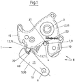
- FIG. 1 shows a plan view of a motor vehicle lock 1, in which the rotary latch 2 moving about the axis 3, the bracket leg 9 of the lock bracket 7 comprises.
- the closed state of a motor vehicle lock 1 is shown, wherein the catch 2 is secured by the pawl axis 6 pivotable pawl 5, ie the motor vehicle lock 1 can only be opened again, if previously the pawl 5 is pivoted away, which is not reproduced here Handle the vehicle door is possible.
- the hanger arm 9 is zoomed over the receptacle 4 to the depth of 27 to the catch 2 and thus secures the closed state of the vehicle door, not shown here, the locking members 30, 31, ie the pawl 5 and the catch 2 are parts of the vehicle door while the lock bracket 7 are fixed to the bracket 9 on the body of the motor vehicle.
- the locking parts 30, 31 of the locking mechanism 8 are produced in a preferably multi-part punching process from corresponding rolled sheets, wherein the surface is characterized by a punched contour 14 at the latching surfaces 12, 13 kept free of the sheath 10 first at both locking parts 30, 31.
- edges 15, 16 of the rotary latch 2 and the pawl 5 are provided with a sheath 10.
- the edges 15, 16 are thus covered by such a sheath 10, only in the region of the locking surfaces 12, 13 and the contact surface 20 between the rotary latch 2 and shackle leg 9, the sheath 10 is not present, so that there the special surface structure as shown in the following Figures can be seen, can be effective.
- the surface structure ensures a noise minimization and a sliding friction minimization, whereby both also cooperate.
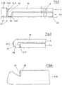
- FIG. 2 shows a pawl 5 in side view, which is clear that this pawl 5 is pivotable about the pawl axis 6 in such a way that the pawl 5 can move over the bottom of the lock case housing 40.
- the free end 59 of the locking member 31 with the punching contour 14 against the free end 58 of the pawl 5, which has an angled portion 60.
- the locking part surface 11 rests with its rolled smooth surface against the free end 59 of the rotary latch 2, so that the existing there straight grooves 17 can not adversely affect.
- Also present on the free end 58 of the pawl 5 straight grooves 17 on the locking surface 13, can not be adversely affected, because they are removed by the angled portion 60 from the region of the contact surface 65.
- the pawl 5 is here secured by a supplementary plate 64 having a thickness which corresponds approximately to the height of the angled portion 60.
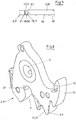
- FIG. 3 shows a particular shape of the bend 60, which is here arcuate, so that a reduced contact surface 65 is formed.
- This part of the bend can have exactly the locking part surface 61 as the rest of the area or else it is treated separately or formed, for example by a coating.
- Pawl 5 and supplementary plate 64 move together.
- the angled portion 60 is shaped such that an arcuate contact surface 65 is produced, which again entails a reduction of the latching surface 13 (contact surface 65).
- FIG. 3 shows a particular shape of the bend 60, which is here arcuate, so that a reduced contact surface 65 is formed.
- This part of the bend can have exactly the locking part surface 61 as the rest of the area or else it is treated separately or formed, for example by a coating.
- the locking surface 13 with the existing straight grooves 17 is harmless, because it is correspondingly far angled.
- Pawl 5 and supplementary plate 64 move together.
- the angled portion 60 is shaped such that an arcuate contact surface 65 is
- FIG. 6 shows a perspective view of the rotary latch 2 which is pivotable about the axis 3.
- the in FIG. 5 is not shown, introduced into the receptacle 4 and later then freed again, so that the vehicle door can then be opened or just closes.
- the Rotary latch 2 locked by the pawl 5.
- FIG. 6 It can be seen that the stamping of the rotary catch 2 produces a clearly recognizable edge 15, the surface of which, as explained further above, is characterized in particular by the punching contour 14 on the latching surface 12. This punching contour 14 is in FIG. 6 only hinted.
- the locking surface 12 indicates the main catch 22, that is, the position in which the pawl 5 prevents the catch 2 in the closed position at a pivoting back.
Landscapes
- Engineering & Computer Science (AREA)
- Mechanical Engineering (AREA)
- Lock And Its Accessories (AREA)
- Portable Nailing Machines And Staplers (AREA)
Claims (10)
- Procédé de fabrication de serrures de véhicules à moteur comportant des pièces de blocage pêne pivotant et cliquet d'arrêt en tôles laminées où le pêne pivotant et cliquet d'arrêt sont estampés donnant des arêtes verticales ou presque verticales avec des surfaces d'enclenchement correspondantes au pêne pivotant et cliquet d'arrêt et ensuite sont pourvus d'une gaine en laissant libres les surfaces d'enclenchement,
caractérisé en ce
qu'après l'estampage, les pièces de blocage sont pliées dans la zone du premier cran et/ou d'un autre cran donnant un contour libre de stries d'estampage et ensuite qui sont installées dans le boîtier de serrure. - Procédé selon la revendication 1
caractérisé en ce
qu'après l'estampage, une pièce de blocage est pliée dans la zone du premier cran et/ou d'un autre cran et ensuite montée et à l'état monté, mise en contact avec l'extrémité libre estampée de l'autre pièce de blocage et donc avec un contour d'estampage droit. - Procédé selon l'une des revendications précédentes
caractérisé en ce que lors du pliage de l'extrémité libre de la pièce de blocage estampée, l'extrémité libre à plier se déforme légèrement en arc autour de son axe transversal. - Procédé selon l'une des revendications précédentes
caractérisé en ce
que lors du pliage de l'extrémité libre de la pièce de blocage estampée, l'extrémité libre se courbe légèrement autour de son axe longitudinal ou l'extrémité libre est fraisée de façon qu'au centre, un dos légèrement arrondi se réalise. - Serrure de véhicule à moteur avec un pêne pivotant (2) et un cliquet d'arrêt (5) bloquant le pêne pivotant (2) à l'état de fermeture, le pêne pivotant (2) et le cliquet d'arrêt (5) présentant des surfaces d'enclenchement (12, 13) sur les bords apparus lors de l'estampage des pièces de blocage à l'extrémité libre des pièces de blocage et une gaine (10) laissant libre ces surfaces d'enclenchement
caractérisée en ce
que les pièces de blocage (30, 31) présentent à leur extrémité (58, 59) libre présentant un contour d'estampage (14) un pli (60) de façon que leur surface de pièce de blocage laminée (61) soit dirigée vers l'extrémité libre (58, 59) de la pièce de blocage voisine (30, 31) et mise en contact avec celle-ci. - Serrure de véhicule à moteur selon la revendication 5,
caractérisée en ce
que le cliquet d'arrêt (5) présente une extrémité (58) libre présentant un contour estampé (14) avec un pli (60) et le pêne pivotant (2) une extrémité (59) libre dirigée vers le pli (60) et étant mise en contact avec celui-ci ou que l'extrémité (59) libre du pêne pivotant (2) est formée disposant du pli (60). - Serrure de véhicule à moteur selon la revendication 5
caractérisée en ce que
le cliquet d'arrêt (5) est réduit à l'épaisseur de la tôle à son extrémité (58) libre et que l'embout (62) saillant est courbé ou plié. - Serrure de véhicule à moteur selon la revendication 5
caractérisée en ce
que le cliquet d'arrêt (5) ou le pêne pivotant (2) présente un pli (60) arrondi à l'extrémité libre (58, 59). - Serrure de véhicule à moteur selon la revendication 5
caractérisée en ce
que le pli (60) est formé, vu sur sa longueur, en forme légèrement courbée. - Serrure de véhicule à moteur selon l'une des revendications précédentes
caractérisée en ce
que le cliquet d'arrêt (5) est affecté à une tôle complémentaire (64) qui présente une épaisseur compensant la hauteur du pli (60).
Applications Claiming Priority (2)
| Application Number | Priority Date | Filing Date | Title |
|---|---|---|---|
| DE102012024302.2A DE102012024302A1 (de) | 2012-12-12 | 2012-12-12 | Kraftfahrzeugtürschloss |
| PCT/DE2013/000772 WO2014090217A2 (fr) | 2012-12-12 | 2013-12-11 | Procédé de fabrication de serrures de véhicules à moteur présentant une surface laminée en tant que contour de partie de cliquet |
Publications (2)
| Publication Number | Publication Date |
|---|---|
| EP2932002A2 EP2932002A2 (fr) | 2015-10-21 |
| EP2932002B1 true EP2932002B1 (fr) | 2017-02-15 |
Family
ID=50349394
Family Applications (1)
| Application Number | Title | Priority Date | Filing Date |
|---|---|---|---|
| EP13840160.9A Active EP2932002B1 (fr) | 2012-12-12 | 2013-12-11 | Procédé de fabrication de serrures de véhicules à moteur présentant une surface laminée en tant que contour de partie de cliquet |
Country Status (11)
| Country | Link |
|---|---|
| US (1) | US9810007B2 (fr) |
| EP (1) | EP2932002B1 (fr) |
| JP (1) | JP2016506462A (fr) |
| KR (1) | KR102155816B1 (fr) |
| CN (1) | CN105189895B (fr) |
| BR (1) | BR112015013724A2 (fr) |
| CA (1) | CA2897848A1 (fr) |
| DE (1) | DE102012024302A1 (fr) |
| MX (1) | MX2015007355A (fr) |
| RU (1) | RU2015127195A (fr) |
| WO (1) | WO2014090217A2 (fr) |
Families Citing this family (9)
| Publication number | Priority date | Publication date | Assignee | Title |
|---|---|---|---|---|
| DE102012207443A1 (de) * | 2012-05-04 | 2013-11-07 | Kiekert Ag | Schloss für eine Klappe oder Tür |
| DE102012024209A1 (de) * | 2012-12-11 | 2014-06-26 | Kiekert Aktiengesellschaft | Kraftfahrzeugtürschloss |
| DE102013110194A1 (de) * | 2013-09-16 | 2015-03-19 | Kiekert Aktiengesellschaft | Kraftfahrzeugstelleinrichtung |
| DE102019107229A1 (de) * | 2019-03-21 | 2020-09-24 | Kiekert Aktiengesellschaft | Türschloss insbesondere Kraftfahrzeugtürschloss |
| DE102019117053A1 (de) * | 2019-06-25 | 2020-12-31 | Kiekert Aktiengesellschaft | Türschloss, insbesondere Kraftfahrzeugtürschloss |
| DE102020100146A1 (de) * | 2020-01-07 | 2021-07-08 | Kiekert Aktiengesellschaft | Kraftfahrzeug-Schloss |
| CN115559622B (zh) * | 2022-10-26 | 2025-06-27 | 麦格纳汽车系统(苏州)有限公司 | 车门锁及车辆 |
| CN115992627B (zh) * | 2023-02-28 | 2024-12-13 | 麦格纳汽车系统(苏州)有限公司 | 车门锁及车辆 |
| DE102023123633A1 (de) * | 2023-09-01 | 2025-03-06 | Brose Schließsysteme GmbH & Co. Kommanditgesellschaft | Verfahren zur Fertigung eines Kraftfahrzeugschlosses |
Family Cites Families (44)
| Publication number | Priority date | Publication date | Assignee | Title |
|---|---|---|---|---|
| JPS5811878Y2 (ja) * | 1977-04-20 | 1983-03-07 | アイシン精機株式会社 | 自動車用ドアロツク装置 |
| US4358141A (en) * | 1979-04-07 | 1982-11-09 | Mitsui Kinzoku Kogyo Kabushiki Kaisha | Noise prevention device in an automobile locking apparatus |
| JP3201969B2 (ja) * | 1997-03-07 | 2001-08-27 | 三井金属鉱業株式会社 | 車両ドアロック装置における衝突時の開扉防止装置 |
| GB0118687D0 (en) * | 2001-08-01 | 2001-09-19 | Arvinmeritor Light Vehicle Sys | Latch arrangement |
| US7175212B2 (en) * | 2002-02-25 | 2007-02-13 | Intier Automotive Closures Inc. | Latch having releasable cinching mechanism |
| DE10320439A1 (de) * | 2003-05-08 | 2004-11-25 | Kiekert Ag | Kraftfahrzeugtürverschluss |
| DE10320457A1 (de) * | 2003-05-08 | 2004-12-16 | Kiekert Ag | Kraftfahrzeugtürverschluss |
| DE102004033735B4 (de) * | 2004-07-13 | 2006-07-27 | Huf Hülsbeck & Fürst Gmbh & Co. Kg | Vorrichtung zur Betätigung von Schlössern an Türen oder Klappen von Fahrzeugen |
| JP4852544B2 (ja) * | 2004-08-10 | 2012-01-11 | マグナ クロージャーズ インコーポレイテッド | パワー解除式二重ロックラッチ |
| EP1724424B1 (fr) | 2005-05-16 | 2009-10-07 | Intier Automotive Closures S.p.A. | Serrure de porte de véhicule |
| EP1734209B1 (fr) * | 2005-06-15 | 2013-08-14 | Intier Automotive Closures S.p.A. | Serrure pour porte de véhicule automobile |
| EP1746230A1 (fr) * | 2005-07-21 | 2007-01-24 | ArvinMeritor Light Vehicle Systems (UK) Ltd | Mécanisme de déverrouillage motorisé |
| US20080224482A1 (en) * | 2007-02-15 | 2008-09-18 | Cumbo Francesco | Electrical Door Latch |
| WO2009069851A1 (fr) * | 2007-11-27 | 2009-06-04 | Austem Co., Ltd. | Ensemble loquet pour siege de vehicule |
| DE202008007719U1 (de) * | 2007-12-03 | 2009-04-16 | BROSE SCHLIEßSYSTEME GMBH & CO. KG | Schließhilfsantrieb für ein Kraftfahrzeugschloß |
| DE102007060626A1 (de) | 2007-12-15 | 2009-06-18 | BROSE SCHLIEßSYSTEME GMBH & CO. KG | Schwenkbar oder verschiebbar gelagerte Paare von in Kontakt bringbaren Kraftübertragungselementen für Verstelleinrichtungen in Kraftfahrzeugen sowie Herstellungs- und Montageverfahren |
| US20100072761A1 (en) * | 2008-02-04 | 2010-03-25 | Kris Tomaszewski | Global Side Door Latch |
| DE102008009506A1 (de) * | 2008-02-15 | 2009-08-20 | Kiekert Ag | Kraftfahrzeugtürverschluss |
| KR100877203B1 (ko) * | 2008-03-04 | 2009-01-07 | (주)대일씨에프티 | 차량용 도어래치 조립체에 설치되는 파울 샤프트 및 이를제조하기 위한 단조방법 |
| WO2009151929A2 (fr) * | 2008-05-27 | 2009-12-17 | Inteva Products Llc. | Verrou de véhicule |
| DE102009020488A1 (de) * | 2008-08-22 | 2010-02-25 | Kiekert Ag | Antriebseinheit mit blockiertem Funktionselement für eine Zentralverriegelung |
| DE102008057961A1 (de) * | 2008-11-19 | 2010-05-20 | Kiekert Ag | Schlosseinheit mit Mehrklinken-Gesperre |
| DE102008063489A1 (de) * | 2008-12-17 | 2010-06-24 | Kiekert Ag | Vorrichtung für ein Kraftfahrzeugschloss |
| US8191516B2 (en) | 2009-03-09 | 2012-06-05 | GM Global Technology Operations LLC | Delayed exhaust engine cycle |
| US8235428B2 (en) * | 2009-07-14 | 2012-08-07 | Kiekert Ag | Lock unit having a slotted pawl |
| US20110133491A1 (en) * | 2009-12-08 | 2011-06-09 | Perkins Donald M | Vehicle door latch |
| DE102010009141A1 (de) | 2010-02-24 | 2011-08-25 | Kiekert AG, 42579 | Kraftfahrzeugschloss mit geräuscharmem Schlossbügel |
| DE102010023919A1 (de) * | 2010-06-16 | 2011-12-22 | Kiekert Ag | Schloss für eine Tür oder Klappe an einem Kraftfahrzeug oder Gebäude mit Blattfeder |
| KR20120005239A (ko) * | 2010-07-08 | 2012-01-16 | (주) 에이 에스 티 | 파인 블랭킹 펀치 |
| US20120126549A1 (en) * | 2010-11-22 | 2012-05-24 | Kosta Papanikolaou | Pawl Isolation Disk |
| KR101254158B1 (ko) * | 2011-01-25 | 2013-04-18 | (주)동아금속 | 자동차용 스트라이커 제조방법 및 스트라이커 |
| KR20120118251A (ko) * | 2011-04-18 | 2012-10-26 | (주) 에이 에스 티 | 베이스 플레이트의 관상 고정공 성형방법 |
| CN104428078B (zh) * | 2012-04-23 | 2017-09-26 | 蒂森克虏伯钢铁欧洲股份公司 | 弯曲复合板的方法以及经这种弯曲的复合板 |
| DE102012024209A1 (de) * | 2012-12-11 | 2014-06-26 | Kiekert Aktiengesellschaft | Kraftfahrzeugtürschloss |
| DE102012024210A1 (de) * | 2012-12-11 | 2014-06-12 | Kiekert Aktiengesellschaft | Kraftfahrzeugtürschloss |
| DE102012024285A1 (de) * | 2012-12-12 | 2014-06-12 | Kiekert Ag | Kraftfahrzeugtürschloss |
| DE102012024379A1 (de) * | 2012-12-12 | 2014-03-27 | Kiekert Aktiengesellschaft | Verfahren zum Herstellen von Kraftfahrzeugschlössern mit tordierter Gesperreteilkante |
| DE102012024303A1 (de) * | 2012-12-12 | 2014-06-12 | Kiekert Aktiengesellschaft | Kraftfahrzeugtürschloss |
| CN104936716B (zh) * | 2013-01-18 | 2016-09-07 | 株式会社神户制钢所 | 热压成形钢构件的制造方法 |
| KR20160030190A (ko) * | 2013-07-05 | 2016-03-16 | 오토테크 엔지니어링 에이.아이.이. | 제어된 변형 배향을 갖는 금속 부품 |
| CN107186034B (zh) * | 2013-09-20 | 2019-03-19 | 新日铁住金株式会社 | 压制成型品的制造装置 |
| KR101821909B1 (ko) * | 2013-10-09 | 2018-01-24 | 신닛테츠스미킨 카부시키카이샤 | 자동차 차체용 구조 부재의 제조 방법 및 프레스 성형 장치 |
| JP6376140B2 (ja) * | 2013-12-25 | 2018-08-22 | 新日鐵住金株式会社 | 自動車部品及び自動車部品の製造方法 |
| RU2654403C2 (ru) * | 2014-04-09 | 2018-05-17 | Ниппон Стил Энд Сумитомо Метал Корпорейшн | Образованное штамповкой изделие, автомобильный конструктивный элемент, включающий в себя изделие, способ изготовления и устройство для изготовления образованного штамповкой изделия |
-
2012
- 2012-12-12 DE DE102012024302.2A patent/DE102012024302A1/de not_active Withdrawn
-
2013
- 2013-12-11 US US14/650,607 patent/US9810007B2/en active Active
- 2013-12-11 KR KR1020157018267A patent/KR102155816B1/ko active Active
- 2013-12-11 RU RU2015127195A patent/RU2015127195A/ru not_active Application Discontinuation
- 2013-12-11 MX MX2015007355A patent/MX2015007355A/es unknown
- 2013-12-11 JP JP2015546852A patent/JP2016506462A/ja active Pending
- 2013-12-11 BR BR112015013724A patent/BR112015013724A2/pt not_active IP Right Cessation
- 2013-12-11 CA CA2897848A patent/CA2897848A1/fr not_active Abandoned
- 2013-12-11 WO PCT/DE2013/000772 patent/WO2014090217A2/fr not_active Ceased
- 2013-12-11 CN CN201380072626.7A patent/CN105189895B/zh active Active
- 2013-12-11 EP EP13840160.9A patent/EP2932002B1/fr active Active
Non-Patent Citations (1)
| Title |
|---|
| None * |
Also Published As
| Publication number | Publication date |
|---|---|
| CN105189895A (zh) | 2015-12-23 |
| DE102012024302A1 (de) | 2014-06-12 |
| BR112015013724A2 (pt) | 2017-07-11 |
| KR20150094704A (ko) | 2015-08-19 |
| CN105189895B (zh) | 2017-03-08 |
| US20150308164A1 (en) | 2015-10-29 |
| CA2897848A1 (fr) | 2014-06-19 |
| KR102155816B1 (ko) | 2020-09-15 |
| JP2016506462A (ja) | 2016-03-03 |
| WO2014090217A3 (fr) | 2014-12-04 |
| MX2015007355A (es) | 2015-09-10 |
| US9810007B2 (en) | 2017-11-07 |
| EP2932002A2 (fr) | 2015-10-21 |
| WO2014090217A2 (fr) | 2014-06-19 |
| RU2015127195A (ru) | 2017-01-11 |
Similar Documents
| Publication | Publication Date | Title |
|---|---|---|
| EP2932002B1 (fr) | Procédé de fabrication de serrures de véhicules à moteur présentant une surface laminée en tant que contour de partie de cliquet | |
| EP2932001B1 (fr) | Procédé de fabrication de serrures de véhicules à moteur comportant des surfaces d'encastrement affectées à une partie de puzzle | |
| EP3230119B1 (fr) | Dispositif de réglage longitudinal d'un siège de véhicule et siège de véhicule | |
| EP2932003B1 (fr) | Procédé de fabrication de serrures de véhicules à moteur comportant un cliquet placé de manière oblique | |
| EP2640916A1 (fr) | Serrure à lèvre élastique modifiée pour portes de véhicule automobile | |
| WO2011103847A2 (fr) | Serrure de véhicule automobile dotée d'un étrier de serrure peu bruyant | |
| DE102012024210A1 (de) | Kraftfahrzeugtürschloss | |
| EP2932004B1 (fr) | Procédé de fabrication de serrures de véhicules à moteur comportant une arête de partie de cliquet tordue | |
| DE102008021802B4 (de) | Türführung eines Fahrzeuges und Verfahren zu deren Herstellung | |
| EP0305731B1 (fr) | Barre de guidage pour un joint d'angle | |
| DE102010026074B4 (de) | Verriegelungsanordnung | |
| EP2932000B1 (fr) | Procédé de fabrication de serrures de véhicules à moteur comportant un contour d'encastrement principal oblique et une serrure de véhicules à moteur | |
| EP2754805A2 (fr) | Tringle de verrouillage pour une crémone | |
| EP2784248B1 (fr) | Agencement d'engrenage pour une ferrure de bielle | |
| EP2243650B1 (fr) | Arrangement d'enjoliveur pour une fenêtre de véhicule automobile | |
| AT512882A1 (de) | Schubladenrückwand | |
| EP4477831A2 (fr) | Meuble et procédé de montage d'une porte coulissante sur un corps de meuble | |
| DE102020104949A1 (de) | Hebel zum manuellen Entriegeln einer Sitzschienenanordnung | |
| DE102010023903B4 (de) | Schloss für eine Tür oder Klappe an einem Kraftfahrzeug oder Gebäude mit Druckstiften | |
| WO2008119460A1 (fr) | Ensemble tringle de crémone constitué d'au moins une tringle et d'au moins un élément de guidage de tringle | |
| EP2860339B1 (fr) | Dispositif anti-levage | |
| DE102010024508A1 (de) | Schlosshalter für Schlösser in Kraftfahrzeugen und Gebäuden mit eine Einschnürung aufweisendem Schließbolzen | |
| DE202020100179U1 (de) | Sektionaltorblatt | |
| DE29705022U1 (de) | Haltevorrichtung zum Haltern eines Vorhangs | |
| DE102009031171A1 (de) | Schlosshalter aus Z-Profil |
Legal Events
| Date | Code | Title | Description |
|---|---|---|---|
| PUAI | Public reference made under article 153(3) epc to a published international application that has entered the european phase |
Free format text: ORIGINAL CODE: 0009012 |
|
| 17P | Request for examination filed |
Effective date: 20150604 |
|
| AK | Designated contracting states |
Kind code of ref document: A2 Designated state(s): AL AT BE BG CH CY CZ DE DK EE ES FI FR GB GR HR HU IE IS IT LI LT LU LV MC MK MT NL NO PL PT RO RS SE SI SK SM TR |
|
| AX | Request for extension of the european patent |
Extension state: BA ME |
|
| DAX | Request for extension of the european patent (deleted) | ||
| GRAP | Despatch of communication of intention to grant a patent |
Free format text: ORIGINAL CODE: EPIDOSNIGR1 |
|
| GRAS | Grant fee paid |
Free format text: ORIGINAL CODE: EPIDOSNIGR3 |
|
| INTG | Intention to grant announced |
Effective date: 20161011 |
|
| GRAA | (expected) grant |
Free format text: ORIGINAL CODE: 0009210 |
|
| AK | Designated contracting states |
Kind code of ref document: B1 Designated state(s): AL AT BE BG CH CY CZ DE DK EE ES FI FR GB GR HR HU IE IS IT LI LT LU LV MC MK MT NL NO PL PT RO RS SE SI SK SM TR |
|
| REG | Reference to a national code |
Ref country code: CH Ref legal event code: EP Ref country code: GB Ref legal event code: FG4D Free format text: NOT ENGLISH |
|
| REG | Reference to a national code |
Ref country code: IE Ref legal event code: FG4D Free format text: LANGUAGE OF EP DOCUMENT: GERMAN |
|
| REG | Reference to a national code |
Ref country code: AT Ref legal event code: REF Ref document number: 868013 Country of ref document: AT Kind code of ref document: T Effective date: 20170315 |
|
| REG | Reference to a national code |
Ref country code: DE Ref legal event code: R096 Ref document number: 502013006396 Country of ref document: DE |
|
| REG | Reference to a national code |
Ref country code: NL Ref legal event code: MP Effective date: 20170215 |
|
| REG | Reference to a national code |
Ref country code: LT Ref legal event code: MG4D |
|
| PG25 | Lapsed in a contracting state [announced via postgrant information from national office to epo] |
Ref country code: GR Free format text: LAPSE BECAUSE OF FAILURE TO SUBMIT A TRANSLATION OF THE DESCRIPTION OR TO PAY THE FEE WITHIN THE PRESCRIBED TIME-LIMIT Effective date: 20170516 Ref country code: LT Free format text: LAPSE BECAUSE OF FAILURE TO SUBMIT A TRANSLATION OF THE DESCRIPTION OR TO PAY THE FEE WITHIN THE PRESCRIBED TIME-LIMIT Effective date: 20170215 Ref country code: FI Free format text: LAPSE BECAUSE OF FAILURE TO SUBMIT A TRANSLATION OF THE DESCRIPTION OR TO PAY THE FEE WITHIN THE PRESCRIBED TIME-LIMIT Effective date: 20170215 Ref country code: NO Free format text: LAPSE BECAUSE OF FAILURE TO SUBMIT A TRANSLATION OF THE DESCRIPTION OR TO PAY THE FEE WITHIN THE PRESCRIBED TIME-LIMIT Effective date: 20170515 Ref country code: HR Free format text: LAPSE BECAUSE OF FAILURE TO SUBMIT A TRANSLATION OF THE DESCRIPTION OR TO PAY THE FEE WITHIN THE PRESCRIBED TIME-LIMIT Effective date: 20170215 |
|
| PG25 | Lapsed in a contracting state [announced via postgrant information from national office to epo] |
Ref country code: RS Free format text: LAPSE BECAUSE OF FAILURE TO SUBMIT A TRANSLATION OF THE DESCRIPTION OR TO PAY THE FEE WITHIN THE PRESCRIBED TIME-LIMIT Effective date: 20170215 Ref country code: LV Free format text: LAPSE BECAUSE OF FAILURE TO SUBMIT A TRANSLATION OF THE DESCRIPTION OR TO PAY THE FEE WITHIN THE PRESCRIBED TIME-LIMIT Effective date: 20170215 Ref country code: ES Free format text: LAPSE BECAUSE OF FAILURE TO SUBMIT A TRANSLATION OF THE DESCRIPTION OR TO PAY THE FEE WITHIN THE PRESCRIBED TIME-LIMIT Effective date: 20170215 Ref country code: SE Free format text: LAPSE BECAUSE OF FAILURE TO SUBMIT A TRANSLATION OF THE DESCRIPTION OR TO PAY THE FEE WITHIN THE PRESCRIBED TIME-LIMIT Effective date: 20170215 Ref country code: NL Free format text: LAPSE BECAUSE OF NON-PAYMENT OF DUE FEES Effective date: 20170215 Ref country code: BG Free format text: LAPSE BECAUSE OF FAILURE TO SUBMIT A TRANSLATION OF THE DESCRIPTION OR TO PAY THE FEE WITHIN THE PRESCRIBED TIME-LIMIT Effective date: 20170515 Ref country code: PT Free format text: LAPSE BECAUSE OF FAILURE TO SUBMIT A TRANSLATION OF THE DESCRIPTION OR TO PAY THE FEE WITHIN THE PRESCRIBED TIME-LIMIT Effective date: 20170615 |
|
| PG25 | Lapsed in a contracting state [announced via postgrant information from national office to epo] |
Ref country code: IT Free format text: LAPSE BECAUSE OF FAILURE TO SUBMIT A TRANSLATION OF THE DESCRIPTION OR TO PAY THE FEE WITHIN THE PRESCRIBED TIME-LIMIT Effective date: 20170215 Ref country code: RO Free format text: LAPSE BECAUSE OF FAILURE TO SUBMIT A TRANSLATION OF THE DESCRIPTION OR TO PAY THE FEE WITHIN THE PRESCRIBED TIME-LIMIT Effective date: 20170215 Ref country code: EE Free format text: LAPSE BECAUSE OF FAILURE TO SUBMIT A TRANSLATION OF THE DESCRIPTION OR TO PAY THE FEE WITHIN THE PRESCRIBED TIME-LIMIT Effective date: 20170215 Ref country code: SK Free format text: LAPSE BECAUSE OF FAILURE TO SUBMIT A TRANSLATION OF THE DESCRIPTION OR TO PAY THE FEE WITHIN THE PRESCRIBED TIME-LIMIT Effective date: 20170215 |
|
| REG | Reference to a national code |
Ref country code: DE Ref legal event code: R097 Ref document number: 502013006396 Country of ref document: DE |
|
| PG25 | Lapsed in a contracting state [announced via postgrant information from national office to epo] |
Ref country code: DK Free format text: LAPSE BECAUSE OF FAILURE TO SUBMIT A TRANSLATION OF THE DESCRIPTION OR TO PAY THE FEE WITHIN THE PRESCRIBED TIME-LIMIT Effective date: 20170215 Ref country code: SM Free format text: LAPSE BECAUSE OF FAILURE TO SUBMIT A TRANSLATION OF THE DESCRIPTION OR TO PAY THE FEE WITHIN THE PRESCRIBED TIME-LIMIT Effective date: 20170215 Ref country code: PL Free format text: LAPSE BECAUSE OF FAILURE TO SUBMIT A TRANSLATION OF THE DESCRIPTION OR TO PAY THE FEE WITHIN THE PRESCRIBED TIME-LIMIT Effective date: 20170215 |
|
| REG | Reference to a national code |
Ref country code: FR Ref legal event code: PLFP Year of fee payment: 5 |
|
| PLBE | No opposition filed within time limit |
Free format text: ORIGINAL CODE: 0009261 |
|
| STAA | Information on the status of an ep patent application or granted ep patent |
Free format text: STATUS: NO OPPOSITION FILED WITHIN TIME LIMIT |
|
| 26N | No opposition filed |
Effective date: 20171116 |
|
| PG25 | Lapsed in a contracting state [announced via postgrant information from national office to epo] |
Ref country code: SI Free format text: LAPSE BECAUSE OF FAILURE TO SUBMIT A TRANSLATION OF THE DESCRIPTION OR TO PAY THE FEE WITHIN THE PRESCRIBED TIME-LIMIT Effective date: 20170215 |
|
| REG | Reference to a national code |
Ref country code: CH Ref legal event code: PL |
|
| GBPC | Gb: european patent ceased through non-payment of renewal fee |
Effective date: 20171211 |
|
| REG | Reference to a national code |
Ref country code: IE Ref legal event code: MM4A |
|
| PG25 | Lapsed in a contracting state [announced via postgrant information from national office to epo] |
Ref country code: LU Free format text: LAPSE BECAUSE OF NON-PAYMENT OF DUE FEES Effective date: 20171211 Ref country code: MT Free format text: LAPSE BECAUSE OF FAILURE TO SUBMIT A TRANSLATION OF THE DESCRIPTION OR TO PAY THE FEE WITHIN THE PRESCRIBED TIME-LIMIT Effective date: 20170215 |
|
| REG | Reference to a national code |
Ref country code: BE Ref legal event code: MM Effective date: 20171231 |
|
| PG25 | Lapsed in a contracting state [announced via postgrant information from national office to epo] |
Ref country code: IE Free format text: LAPSE BECAUSE OF NON-PAYMENT OF DUE FEES Effective date: 20171211 |
|
| PG25 | Lapsed in a contracting state [announced via postgrant information from national office to epo] |
Ref country code: GB Free format text: LAPSE BECAUSE OF NON-PAYMENT OF DUE FEES Effective date: 20171211 Ref country code: BE Free format text: LAPSE BECAUSE OF NON-PAYMENT OF DUE FEES Effective date: 20171231 Ref country code: CH Free format text: LAPSE BECAUSE OF NON-PAYMENT OF DUE FEES Effective date: 20171231 Ref country code: LI Free format text: LAPSE BECAUSE OF NON-PAYMENT OF DUE FEES Effective date: 20171231 |
|
| PG25 | Lapsed in a contracting state [announced via postgrant information from national office to epo] |
Ref country code: MC Free format text: LAPSE BECAUSE OF FAILURE TO SUBMIT A TRANSLATION OF THE DESCRIPTION OR TO PAY THE FEE WITHIN THE PRESCRIBED TIME-LIMIT Effective date: 20170215 Ref country code: HU Free format text: LAPSE BECAUSE OF FAILURE TO SUBMIT A TRANSLATION OF THE DESCRIPTION OR TO PAY THE FEE WITHIN THE PRESCRIBED TIME-LIMIT; INVALID AB INITIO Effective date: 20131211 |
|
| PG25 | Lapsed in a contracting state [announced via postgrant information from national office to epo] |
Ref country code: CY Free format text: LAPSE BECAUSE OF FAILURE TO SUBMIT A TRANSLATION OF THE DESCRIPTION OR TO PAY THE FEE WITHIN THE PRESCRIBED TIME-LIMIT Effective date: 20170215 |
|
| PG25 | Lapsed in a contracting state [announced via postgrant information from national office to epo] |
Ref country code: MK Free format text: LAPSE BECAUSE OF FAILURE TO SUBMIT A TRANSLATION OF THE DESCRIPTION OR TO PAY THE FEE WITHIN THE PRESCRIBED TIME-LIMIT Effective date: 20170215 |
|
| REG | Reference to a national code |
Ref country code: AT Ref legal event code: MM01 Ref document number: 868013 Country of ref document: AT Kind code of ref document: T Effective date: 20181211 |
|
| PG25 | Lapsed in a contracting state [announced via postgrant information from national office to epo] |
Ref country code: TR Free format text: LAPSE BECAUSE OF FAILURE TO SUBMIT A TRANSLATION OF THE DESCRIPTION OR TO PAY THE FEE WITHIN THE PRESCRIBED TIME-LIMIT Effective date: 20170215 |
|
| PG25 | Lapsed in a contracting state [announced via postgrant information from national office to epo] |
Ref country code: AT Free format text: LAPSE BECAUSE OF NON-PAYMENT OF DUE FEES Effective date: 20181211 |
|
| PG25 | Lapsed in a contracting state [announced via postgrant information from national office to epo] |
Ref country code: AL Free format text: LAPSE BECAUSE OF FAILURE TO SUBMIT A TRANSLATION OF THE DESCRIPTION OR TO PAY THE FEE WITHIN THE PRESCRIBED TIME-LIMIT Effective date: 20170215 Ref country code: IS Free format text: LAPSE BECAUSE OF FAILURE TO SUBMIT A TRANSLATION OF THE DESCRIPTION OR TO PAY THE FEE WITHIN THE PRESCRIBED TIME-LIMIT Effective date: 20170615 |
|
| P01 | Opt-out of the competence of the unified patent court (upc) registered |
Effective date: 20230529 |
|
| PGFP | Annual fee paid to national office [announced via postgrant information from national office to epo] |
Ref country code: FR Payment date: 20251218 Year of fee payment: 13 |
|
| PGFP | Annual fee paid to national office [announced via postgrant information from national office to epo] |
Ref country code: CZ Payment date: 20251204 Year of fee payment: 13 |
|
| PGFP | Annual fee paid to national office [announced via postgrant information from national office to epo] |
Ref country code: DE Payment date: 20251222 Year of fee payment: 13 |