EP2932002B1 - Method for producing motor vehicle door locks with a rolling surface as a locking part contour - Google Patents
Method for producing motor vehicle door locks with a rolling surface as a locking part contour Download PDFInfo
- Publication number
- EP2932002B1 EP2932002B1 EP13840160.9A EP13840160A EP2932002B1 EP 2932002 B1 EP2932002 B1 EP 2932002B1 EP 13840160 A EP13840160 A EP 13840160A EP 2932002 B1 EP2932002 B1 EP 2932002B1
- Authority
- EP
- European Patent Office
- Prior art keywords
- pawl
- free end
- catch
- motor vehicle
- locking
- Prior art date
- Legal status (The legal status is an assumption and is not a legal conclusion. Google has not performed a legal analysis and makes no representation as to the accuracy of the status listed.)
- Active
Links
Images
Classifications
-
- E—FIXED CONSTRUCTIONS
- E05—LOCKS; KEYS; WINDOW OR DOOR FITTINGS; SAFES
- E05B—LOCKS; ACCESSORIES THEREFOR; HANDCUFFS
- E05B85/00—Details of vehicle locks not provided for in groups E05B77/00 - E05B83/00
- E05B85/20—Bolts or detents
- E05B85/22—Rectilinearly moving bolts
-
- B—PERFORMING OPERATIONS; TRANSPORTING
- B21—MECHANICAL METAL-WORKING WITHOUT ESSENTIALLY REMOVING MATERIAL; PUNCHING METAL
- B21D—WORKING OR PROCESSING OF SHEET METAL OR METAL TUBES, RODS OR PROFILES WITHOUT ESSENTIALLY REMOVING MATERIAL; PUNCHING METAL
- B21D53/00—Making other particular articles
- B21D53/38—Making other particular articles locksmith's goods, e.g. handles
-
- B—PERFORMING OPERATIONS; TRANSPORTING
- B21—MECHANICAL METAL-WORKING WITHOUT ESSENTIALLY REMOVING MATERIAL; PUNCHING METAL
- B21D—WORKING OR PROCESSING OF SHEET METAL OR METAL TUBES, RODS OR PROFILES WITHOUT ESSENTIALLY REMOVING MATERIAL; PUNCHING METAL
- B21D22/00—Shaping without cutting, by stamping, spinning, or deep-drawing
- B21D22/02—Stamping using rigid devices or tools
-
- B—PERFORMING OPERATIONS; TRANSPORTING
- B21—MECHANICAL METAL-WORKING WITHOUT ESSENTIALLY REMOVING MATERIAL; PUNCHING METAL
- B21D—WORKING OR PROCESSING OF SHEET METAL OR METAL TUBES, RODS OR PROFILES WITHOUT ESSENTIALLY REMOVING MATERIAL; PUNCHING METAL
- B21D5/00—Bending sheet metal along straight lines, e.g. to form simple curves
-
- E—FIXED CONSTRUCTIONS
- E05—LOCKS; KEYS; WINDOW OR DOOR FITTINGS; SAFES
- E05B—LOCKS; ACCESSORIES THEREFOR; HANDCUFFS
- E05B77/00—Vehicle locks characterised by special functions or purposes
- E05B77/36—Noise prevention; Anti-rattling means
-
- E—FIXED CONSTRUCTIONS
- E05—LOCKS; KEYS; WINDOW OR DOOR FITTINGS; SAFES
- E05B—LOCKS; ACCESSORIES THEREFOR; HANDCUFFS
- E05B79/00—Mounting or connecting vehicle locks or parts thereof
- E05B79/10—Connections between movable lock parts
-
- E—FIXED CONSTRUCTIONS
- E05—LOCKS; KEYS; WINDOW OR DOOR FITTINGS; SAFES
- E05B—LOCKS; ACCESSORIES THEREFOR; HANDCUFFS
- E05B85/00—Details of vehicle locks not provided for in groups E05B77/00 - E05B83/00
- E05B85/20—Bolts or detents
- E05B85/24—Bolts rotating about an axis
- E05B85/26—Cooperation between bolts and detents
-
- E—FIXED CONSTRUCTIONS
- E05—LOCKS; KEYS; WINDOW OR DOOR FITTINGS; SAFES
- E05B—LOCKS; ACCESSORIES THEREFOR; HANDCUFFS
- E05B77/00—Vehicle locks characterised by special functions or purposes
- E05B77/36—Noise prevention; Anti-rattling means
- E05B77/40—Lock elements covered by silencing layers, e.g. coatings
Definitions
- the invention relates to a method for producing motor vehicle locks with the locking parts catch and pawl, in which the rotary latch and the pawl punched out of rolled sheets perpendicular or approximately vertical edges with corresponding locking surfaces of the catch and pawl predefined and then provided with free space of the locking surfaces with a sheath become.
- the invention also relates to a motor vehicle lock with a catch and a locking latch locking the latch in the closed state, wherein catch and pawl have corresponding locking surfaces on the resulting edges of the locking parts at the free end of the locking parts and these locking surfaces free sheathing.
- the present invention is based on the object to provide a manufacturing method and a motor vehicle lock, in which the creaking between the catch and pawl is avoided.
- the object is procedurally achieved in that the locking parts angled after punching in the region of the main catch and / or another rest stanzriefenfill a contour and then inserted into the lock housing box.
- the locking parts ie both the pawl and the catch are punched out of rolled sheets, so that the surfaces of both locking parts are smooth.
- the invention makes use of this by at least one of the free ends of the locking parts is angled or bent in the region of the main catch and / or other detent areas, so that then not a free end of a stamped part bears against another free end of a stamped part, but that by the angling of one end of a locking part or both ends now the bent rolled surface of the or the locking parts are adjacent to each other, so that the grooves or grooves having punching contours with the movement of both locking parts can no longer interact with each other.
- the described adverse creaking noises can no longer occur and it is also excluded that the free ends with the resulting by punching grooves against each other and then interlock with each other.
- a locking part is bent after punching in the region of the main catch and / or another catch and then mounted and brought in the assembled state with the free punched end of the other locking part and thus a straight punched contour in contact ,
- the locking surface of the two locking parts which come into contact with the movement during the movement or when supporting the catch by the pawl, are greatly reduced in terms of area, as provided according to the invention when bending the free end of the stamped locking part the angled free end slightly curved arcuately about its transverse axis becomes.
- the shape of the bend or the arcuate bend can be chosen so that only a small contact surface or just a slightly larger contact surface between the two locking parts remains, depending on how this proves to be useful in one or the other motor vehicle lock.
- Another way to reduce the size of the contact surface in the region of the locking surfaces is that, when bending the free end of the stamped locking part, the free end is slightly bent about its longitudinal axis or the free end is milled, so that the center creates a slightly rounded back.
- the milling has the advantage that this results in grooves that are inclined in a certain proportion to the vertical Stamping contour of the other locking part are executed, so that a reduction of the sliding friction is achieved here safely.
- the device for solving the problem that the locking parts have at their free, a punching contour having end angling, so that their rolled locking member surface is directed against the free end of the adjacent locking member with this in abutment.
- a trained locking part or appropriately trained locking parts make it possible that the catch and the pawl does not come to rest with the punching contour having free ends together, but rather with the rolled locking part surface, the emergence of the due to the smoothness caused by the rolling excludes adverse stick-slip effect.
- the pawl has a punched contour exhibiting free end with an angled portion and the catch a free, directed against the bend and there to plant to bring free end or that the free end of the catch formed on the bend is.
- Such an embodiment is already useful because the manufacturing cost is reduced, because only one of the two free ends of the locking parts must be angled, while the other free end remains unchanged with its punching contour in action.
- the remaining on the free end, for example, the rotary latch punching contour is noiseless harmless because the existing grooves of the punching contour easily roll on the smooth surface of the bend or to be able to move grinding. This is true even if only the rotary latch has, for example, an angling, while the free end of the pawl has the disadvantageous punch marks.
- the pawl is reduced at the free end in the plate thickness and the protruding end piece is bent or angled. Assuming that the pawl is a 4 mm thick component, so would reduce the plate thickness, for example, to about 2 mm at the free end, then to bend or bend the projecting tail, this has the advantage that the pawl then can easily rest on the lock case housing floor.
- the pawl should be associated with a supplementary plate having a height compensating the height of the angled portion. Even with this training so the angling would not affect the positioning of the pawl in the lock case housing, because is wororg for a smooth support of the pawl on the bottom of the lock box housing.
- the invention is characterized in particular by the fact that with a small additional manufacturing effort, a motor vehicle can be created in which the pawl and the catch in the rest area so in the area where they are both on or against each other are formed so that the previous noise pollution significantly minimized or completely prevented.
- a uniform movement is ensured along the rotary latch, because the existing configuration of the pawl or possibly the catch the existing grooves of the punch contour can not react with each other, because the corresponding punching contour of the two locking parts or both locking parts bent so in another position is brought.
- the different grooves generated during punching can therefore not interlock and lead to harmful noises.
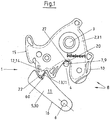
- FIG. 1 shows a plan view of a motor vehicle lock 1, in which the rotary latch 2 moving about the axis 3, the bracket leg 9 of the lock bracket 7 comprises.
- the closed state of a motor vehicle lock 1 is shown, wherein the catch 2 is secured by the pawl axis 6 pivotable pawl 5, ie the motor vehicle lock 1 can only be opened again, if previously the pawl 5 is pivoted away, which is not reproduced here Handle the vehicle door is possible.
- the hanger arm 9 is zoomed over the receptacle 4 to the depth of 27 to the catch 2 and thus secures the closed state of the vehicle door, not shown here, the locking members 30, 31, ie the pawl 5 and the catch 2 are parts of the vehicle door while the lock bracket 7 are fixed to the bracket 9 on the body of the motor vehicle.
- the locking parts 30, 31 of the locking mechanism 8 are produced in a preferably multi-part punching process from corresponding rolled sheets, wherein the surface is characterized by a punched contour 14 at the latching surfaces 12, 13 kept free of the sheath 10 first at both locking parts 30, 31.
- edges 15, 16 of the rotary latch 2 and the pawl 5 are provided with a sheath 10.
- the edges 15, 16 are thus covered by such a sheath 10, only in the region of the locking surfaces 12, 13 and the contact surface 20 between the rotary latch 2 and shackle leg 9, the sheath 10 is not present, so that there the special surface structure as shown in the following Figures can be seen, can be effective.
- the surface structure ensures a noise minimization and a sliding friction minimization, whereby both also cooperate.
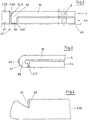
- FIG. 2 shows a pawl 5 in side view, which is clear that this pawl 5 is pivotable about the pawl axis 6 in such a way that the pawl 5 can move over the bottom of the lock case housing 40.
- the free end 59 of the locking member 31 with the punching contour 14 against the free end 58 of the pawl 5, which has an angled portion 60.
- the locking part surface 11 rests with its rolled smooth surface against the free end 59 of the rotary latch 2, so that the existing there straight grooves 17 can not adversely affect.
- Also present on the free end 58 of the pawl 5 straight grooves 17 on the locking surface 13, can not be adversely affected, because they are removed by the angled portion 60 from the region of the contact surface 65.
- the pawl 5 is here secured by a supplementary plate 64 having a thickness which corresponds approximately to the height of the angled portion 60.
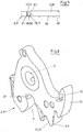
- FIG. 3 shows a particular shape of the bend 60, which is here arcuate, so that a reduced contact surface 65 is formed.
- This part of the bend can have exactly the locking part surface 61 as the rest of the area or else it is treated separately or formed, for example by a coating.
- Pawl 5 and supplementary plate 64 move together.
- the angled portion 60 is shaped such that an arcuate contact surface 65 is produced, which again entails a reduction of the latching surface 13 (contact surface 65).
- FIG. 3 shows a particular shape of the bend 60, which is here arcuate, so that a reduced contact surface 65 is formed.
- This part of the bend can have exactly the locking part surface 61 as the rest of the area or else it is treated separately or formed, for example by a coating.
- the locking surface 13 with the existing straight grooves 17 is harmless, because it is correspondingly far angled.
- Pawl 5 and supplementary plate 64 move together.
- the angled portion 60 is shaped such that an arcuate contact surface 65 is
- FIG. 6 shows a perspective view of the rotary latch 2 which is pivotable about the axis 3.
- the in FIG. 5 is not shown, introduced into the receptacle 4 and later then freed again, so that the vehicle door can then be opened or just closes.
- the Rotary latch 2 locked by the pawl 5.
- FIG. 6 It can be seen that the stamping of the rotary catch 2 produces a clearly recognizable edge 15, the surface of which, as explained further above, is characterized in particular by the punching contour 14 on the latching surface 12. This punching contour 14 is in FIG. 6 only hinted.
- the locking surface 12 indicates the main catch 22, that is, the position in which the pawl 5 prevents the catch 2 in the closed position at a pivoting back.
Landscapes
- Engineering & Computer Science (AREA)
- Mechanical Engineering (AREA)
- Lock And Its Accessories (AREA)
- Portable Nailing Machines And Staplers (AREA)
Description
Verfahren zum Herstellen von Kraftfahrzeugschlössern mit einer Walzfläche als SperrteilkonturMethod for producing motor vehicle locks with a rolling surface as a locking part contour
Die Erfindung betrifft ein Verfahren zum Herstellen von Kraftfahrzeugschlössern mit den Gesperreteilen Drehfalle und Sperrklinke, bei dem die Drehfalle und die Sperrklinke aus gewalzten Blechen senkrechte oder annähernd senkrechte Kanten mit korrespondierenden Rastflächen an Drehfalle und Sperrklinke vorgebend ausgestanzt und anschließend unter Freihaltung der Rastflächen mit einer Ummantelung versehen werden. Die Erfindung betrifft außerdem ein Kraftfahrzeugschloss mit einer Drehfalle und einer die Drehfalle im Schließzustand arretierenden Sperrklinke, wobei Drehfalle und Sperrklinke korrespondierende Rastflächen auf den beim Stanzen der Gesperreteile entstehenden Kanten am freien Ende der Gesperreteile und eine diese Rastflächen freilassende Ummantelung aufweisen.The invention relates to a method for producing motor vehicle locks with the locking parts catch and pawl, in which the rotary latch and the pawl punched out of rolled sheets perpendicular or approximately vertical edges with corresponding locking surfaces of the catch and pawl predefined and then provided with free space of the locking surfaces with a sheath become. The invention also relates to a motor vehicle lock with a catch and a locking latch locking the latch in the closed state, wherein catch and pawl have corresponding locking surfaces on the resulting edges of the locking parts at the free end of the locking parts and these locking surfaces free sheathing.
Es ist grundsätzlich bekannt, die beim Fahren des Kraftfahrzeuges auftretenden Knarzgeräusche, die zwischen Bügelschenkel und Drehfalle auftreten können, dadurch zu verringern, dass man entweder den Bügelschenkel oder auch die Drehfalle im Kontaktbereich beider mit einer Oberflächenstruktur versieht, die zu einer Verringerung der Gleitreibung beiträgt. Dabei werden nach der
Der vorliegenden Erfindung liegt nun die Aufgabe zugrunde, ein Herstellungsverfahren und ein Kraftfahrzeugschloss zu schaffen, bei denen das Knarzen zwischen Drehfalle und Sperrklinke vermieden wird.The present invention is based on the object to provide a manufacturing method and a motor vehicle lock, in which the creaking between the catch and pawl is avoided.
Die Aufgabe wird verfahrensmäßig dadurch gelöst, dass die Gesperreteile nach dem Stanzen im Bereich der Hauptrast und/oder einer anderen Rast eine stanzriefenfreie Kontur ergebend abgewinkelt und dann in den Schlossgehäusekasten eingesetzt werden.The object is procedurally achieved in that the locking parts angled after punching in the region of the main catch and / or another rest stanzriefenfreie a contour and then inserted into the lock housing box.
Die Gesperreteile, d. h. sowohl die Sperrklinke wie auch die Drehfalle werden aus gewalzten Blechen herausgestanzt, sodass die Oberflächen beider Gesperreteile glatt sind. Die Erfindung macht sich dies zu Nutze, indem im Bereich der Hauptrast und/oder auch anderer Rastbereiche zumindest eine der freien Enden der Gesperreteile abgewinkelt oder abgebogen wird, sodass dann nicht ein freies Ende eines Stanzteils gegen ein anderes freies Ende eines Stanzteils anliegt, sondern dass durch das Abwinkeln eines Endes eines Gesperreteils oder auch beider Enden nunmehr die umgebogene gewalzte Oberfläche des oder der Gesperreteile aneinander liegen, sodass die Riefen oder Rillen aufweisenden Stanzkonturen beim Bewegungsablauf beider Gesperreteile miteinander keine Wirkung mehr entfalten können. Dadurch können die beschriebenen nachteiligen Knarzgeräusche nicht mehr auftreten und es ist auch ausgeschlossen, dass die freien Enden mit den durch das Stanzen darauf entstandenen Riefen gegeneinander stehen und dann miteinander verhaken.The locking parts, ie both the pawl and the catch are punched out of rolled sheets, so that the surfaces of both locking parts are smooth. The invention makes use of this by at least one of the free ends of the locking parts is angled or bent in the region of the main catch and / or other detent areas, so that then not a free end of a stamped part bears against another free end of a stamped part, but that by the angling of one end of a locking part or both ends now the bent rolled surface of the or the locking parts are adjacent to each other, so that the grooves or grooves having punching contours with the movement of both locking parts can no longer interact with each other. As a result, the described adverse creaking noises can no longer occur and it is also excluded that the free ends with the resulting by punching grooves against each other and then interlock with each other.
Nach einer zweckmäßigen Ausführungsform der Erfindung ist vorgesehen, dass ein Gesperreteil nach dem Stanzen im Bereich der Hauptrast und/oder einer anderen Rast abgewinkelt und dann montiert und im montierten Zustand mit dem freien gestanzten Ende des anderen Gesperreteils und damit einer geraden Stanzkontur in Kontakt gebracht wird. Dies bedeutet, dass nur ein freies Ende eines Gesperreteils umgebogen bzw. abgewinkelt wird, während das andere so verbleibt, sodass nun die stanzriefenfreie Kontur des abgewinkelten Endes gegen das Ende ansteht, das noch die Stanzkonturen und die Riefen aufweist. Aufgrund der umgebogenen gewalzten Oberfläche kann es auch bei einer ausgeprägten Stanzkontur mit geraden Riefen nicht mehr zu den nachteiligen Geräuschen und einer Erschwerung des Bewegungsablaufes der Sperrklinke entlang der Drehfalle kommen.According to an advantageous embodiment of the invention, it is provided that a locking part is bent after punching in the region of the main catch and / or another catch and then mounted and brought in the assembled state with the free punched end of the other locking part and thus a straight punched contour in contact , This means that only one free end of a locking part is bent or angled while the other remains so that now the punch-free contour of the angled end is present against the end, which still has the punched contours and the grooves. Due to the bent rolled surface, even with a pronounced punching contour with straight grooves, it is no longer possible for the disadvantageous noises and an aggravation of the movement sequence of the pawl to occur along the rotary latch.
Die Rastfläche der beiden Gesperreteile, die beim Bewegungsablauf bzw. auch beim Abstützten der Drehfalle durch die Sperrklinke in Berührung kommen, werden flächenmäßig stark reduziert, wenn wie erfindungsgemäß vorgesehen beim Abwinkeln des freien Endes des gestanzten Gesperreteils das abzuwinkelnde freie Ende leicht um seine Querachse bogenförmig verformt wird. Dabei kann die Form der Abwinklung bzw. der bogenförmigen Abwinklung so gewählt werden, dass nur eine geringe Berührungsfläche oder eben eine etwas größere Berührungsfläche zwischen beiden Gesperreteilen verbleibt, je nachdem wie sich dies bei dem einen oder anderen Kraftfahrzeugschloss als zweckmäßig erweist.The locking surface of the two locking parts, which come into contact with the movement during the movement or when supporting the catch by the pawl, are greatly reduced in terms of area, as provided according to the invention when bending the free end of the stamped locking part the angled free end slightly curved arcuately about its transverse axis becomes. In this case, the shape of the bend or the arcuate bend can be chosen so that only a small contact surface or just a slightly larger contact surface between the two locking parts remains, depending on how this proves to be useful in one or the other motor vehicle lock.
Eine andere Möglichkeit, die Größe der Berührungsfläche im Bereich der Rastflächen zu reduzieren ist die, bei der beim Abwinkeln des freien Endes des gestanzten Gesperreteils das freie Ende um seine Längsachse geringfügig gebogen oder das freie Ende abgefräst wird, sodass mittig ein leicht gerundeter Rücken entsteht. Auch hier kann durch die Ausbildung des Rückens der Bewegungsablauf berücksichtigt werden, wobei das Abfräsen den Vorteil hat, dass dadurch Rillen entstehen, die im bestimmten Verhältnis geneigt zu der senkrechten Stanzkontur des anderen Gesperreteils ausgeführt sind, sodass auch hierbei eine Reduzierung der Gleitreibung sicher erreicht wird.Another way to reduce the size of the contact surface in the region of the locking surfaces is that, when bending the free end of the stamped locking part, the free end is slightly bent about its longitudinal axis or the free end is milled, so that the center creates a slightly rounded back. Here, too, can be taken into account by the formation of the back of the movement, the milling has the advantage that this results in grooves that are inclined in a certain proportion to the vertical Stamping contour of the other locking part are executed, so that a reduction of the sliding friction is achieved here safely.
Vorrichtungsgemäß ist zur Lösung der Aufgabe vorgesehen, dass die Gesperreteile an ihren freien, eine Stanzkontur aufweisenden Ende eine Abwinklung aufweisen, sodass ihre gewalzte Gesperreteileoberfläche gegen das freie Ende des benachbarten Gesperreteils gerichtet mit dieser in Anlage zu bringen ist. Ein derart ausgebildetes Gesperreteil bzw. entsprechend ausgebildete Gesperreteile machen es möglich, dass die Drehfalle und die Sperrklinke nicht mit den eine Stanzkontur aufweisenden freien Enden aneinander zu liegen kommen, sondern vielmehr mit der gewalzten Gesperreteilenoberfläche, die wegen der durch das Walzen entstandenen Glätte das Entstehen des nachteiligen Stick-Slip-Effektes ausschließt.According to the device is provided for solving the problem that the locking parts have at their free, a punching contour having end angling, so that their rolled locking member surface is directed against the free end of the adjacent locking member with this in abutment. Such a trained locking part or appropriately trained locking parts make it possible that the catch and the pawl does not come to rest with the punching contour having free ends together, but rather with the rolled locking part surface, the emergence of the due to the smoothness caused by the rolling excludes adverse stick-slip effect.
Nach einer zweckmäßigen Ausführungsform ist vorgesehen, dass die Sperrklinke ein eine Stanzkontur aufweisendes freies Ende mit einer Abwinklung und die Drehfalle ein freies, gegen die Abwinklung gerichtetes und dort zur Anlage zu bringendes freies Ende aufweist oder dass das freie Ende der Drehfalle über die Abwinklung verfügend ausgebildet ist. Eine solche Ausführungsform ist schon deshalb zweckmäßig, weil der Herstellungsaufwand verringert ist, weil nur eines der beiden freien Enden einer der Gesperreteile abgewinkelt werden muss, während das andere freie Ende unverändert mit seiner Stanzkontur in Aktion bleibt. Die auf dem freien Ende beispielsweise der Drehfalle verbleibende Stanzkontur ist geräuschmäßig unschädlich, weil die vorhandenen Riefen der Stanzkontur problemlos auf der glatten Oberfläche der Abwinklung sich abrollen bzw. sich schleifend bewegen zu können. Dies trifft auch dann zu, wenn nur die Drehfalle beispielsweise über eine Abwinklung verfügt, während das freie Ende der Sperrklinke die an sich nachteiligen Stanzriefen aufweist.According to an expedient embodiment, it is provided that the pawl has a punched contour exhibiting free end with an angled portion and the catch a free, directed against the bend and there to plant to bring free end or that the free end of the catch formed on the bend is. Such an embodiment is already useful because the manufacturing cost is reduced, because only one of the two free ends of the locking parts must be angled, while the other free end remains unchanged with its punching contour in action. The remaining on the free end, for example, the rotary latch punching contour is noiseless harmless because the existing grooves of the punching contour easily roll on the smooth surface of the bend or to be able to move grinding. This is true even if only the rotary latch has, for example, an angling, while the free end of the pawl has the disadvantageous punch marks.
Um eine zweckmäßige Abwinklung zu ermöglichen, ist vorgesehen, dass die Sperrklinke am freien Ende in der Blechstärke reduziert und das überstehende Endstück abgebogen bzw. abgewinkelt ist. Geht man davon aus, dass die Sperrklinke ein rund 4 mm dickes Bauteil ist, würde also am freien Ende die Blechstärke beispielsweise auf rund 2 mm reduziert, um dann das überstehende Endstück abzubiegen bzw. abzuwinkeln, wobei dies den Vorteil hat, dass die Sperrklinke dann problemlos auf dem Schlosskastengehäuseboden aufliegen kann.In order to enable a suitable bending, it is provided that the pawl is reduced at the free end in the plate thickness and the protruding end piece is bent or angled. Assuming that the pawl is a 4 mm thick component, so would reduce the plate thickness, for example, to about 2 mm at the free end, then to bend or bend the projecting tail, this has the advantage that the pawl then can easily rest on the lock case housing floor.
Ist eine solche Reduzierung der Abwinklung nicht möglich, sollte gemäß der vorliegenden Erfindung der Sperrklinke ein Ergänzungsblech zugeordnet sein, das eine die Höhe der Abwinklung ausgleichende Dicke aufweist. Auch bei dieser Ausbildung würde also die Abwinklung die Positionierung der Sperrklinke im Schlosskastengehäuse nicht beeinträchtigen können, weil für eine glatte Auflage der Sperrklinke auf dem Boden des Schlosskastengehäuses gesorg ist.If such a reduction of the angling is not possible, according to the present invention, the pawl should be associated with a supplementary plate having a height compensating the height of the angled portion. Even with this training so the angling would not affect the positioning of the pawl in the lock case housing, because is wororg for a smooth support of the pawl on the bottom of the lock box housing.
Will man eine geringere Anlagefläche beispielsweise zwischen Sperrklinke und Drehfalle erreichen, so ist dies dadurch möglich, dass die Sperrklinke oder die Drehfalle am freien Ende eine abgerollte Abwinklung aufweisen. Zum Einen wird dadurch die Dicke des eventuellen Ergänzungsbleches geringer sein können und zum Anderen ist es so möglich, die eigentliche Rastfläche also die Fläche, in der sich Drehfalle und Sperrklinke berühren, weiter zu reduzieren, weil eben nur in der streifenförmigen Längsrichtung der abgerollten Abwinklung eine Berührung zwischen den Gesperreteilen möglich ist. Durch die Formgebung der abgerollten Abwinklung bzw. ihres Rückens können die Abmaße der wirksamen Abwinklung genau bestimmt werden.If you want to achieve a smaller contact surface, for example, between pawl and rotary latch, this is possible because the pawl or the rotary latch at the free end have a rolled-off angled. On the one hand thereby the thickness of the possible supplemental sheet can be smaller and on the other hand it is possible, the actual locking surface thus the surface in which catch and pawl touch, continue to reduce, because just just in the strip-shaped longitudinal direction of the rolled angled Contact between the locking parts is possible. By shaping the unrolled bend or its back, the dimensions of the effective bend can be accurately determined.
Ähnlich ist dies auch dann, wenn die Abwinklung über ihre Länge gesehen leicht bogenförmig ausgebildet ist, wobei dann die Anlage im Mittelpunkt des Bogens erfolgt und bezüglich der Abmessungen die Größe der Anlage durch eine entsprechende Bearbeitung bzw. Formgebung der bogenförmigen Abwinklung erreicht und eingestellt werden kann.This is similar even if the bend seen over its length is slightly arcuate, in which case the plant is in the center of the arc and the dimensions of the plant by a size appropriate processing or shaping of the arcuate bend can be achieved and adjusted.
Die Erfindung zeichnet sich insbesondere dadurch aus, dass mit einem geringen zusätzlichen Herstellungsaufwand ein Kraftfahrzeug geschaffen werden kann, bei dem die Sperrklinke und die Drehfalle im Rastbereich also in dem Bereich, wo sie beide aufeinander oder aneinander liegen so ausgebildet sind, dass die bisherige Geräuschbelastung deutlich minimiert oder ganz verhindert ist. Außerdem wird eine gleichförmige Bewegung an der Drehfalle entlang sichergestellt, weil durch die besondere Ausbildung der Sperrklinke bzw. ggf. auch der Drehfalle die vorhandenen Riefen der Stanzkontur nicht miteinander reagieren können, weil die entsprechende Stanzkontur eines der beiden Gesperreteile oder auch beider Gesperreteile abgebogen also in eine andere Position gebracht ist. Die unterschiedlichen, beim Stanzen erzeugten Riefen können also nicht ineinander greifen und zu schädlichen Geräuschen führen. Die "herausnahme" der problematischen Rastfläche eines der Gesperreteile aus dem Bewegungsablauf hat aber auch noch den Vorteil, dass die nun zur Verfügung stehende Gesperreteileoberfläche besonders glatt ist, sodass der Bewegungsablauf zwischen Drehfalle und Sperrklinke begünstigt ist.The invention is characterized in particular by the fact that with a small additional manufacturing effort, a motor vehicle can be created in which the pawl and the catch in the rest area so in the area where they are both on or against each other are formed so that the previous noise pollution significantly minimized or completely prevented. In addition, a uniform movement is ensured along the rotary latch, because the existing configuration of the pawl or possibly the catch the existing grooves of the punch contour can not react with each other, because the corresponding punching contour of the two locking parts or both locking parts bent so in another position is brought. The different grooves generated during punching can therefore not interlock and lead to harmful noises. The "exception" of the problematic locking surface of the locking parts from the movement but also has the advantage that the now available locking part surface is particularly smooth, so that the movement between the catch and pawl is favored.
Weitere Einzelheiten und Vorteile des Erfindungsgegenstandes ergeben sich aus der nachfolgenden Beschreibung der zugehörigen Zeichnung, in der ein bevorzugtes Ausführungsbeispiel mit den dazu notwendigen Einzelheiten und Einzelteilen dargestellt ist. Es zeigen:
Figur 1- eine Draufsicht auf ein Kraftfahrzeugschloss im geschlossenen Zustand,
- Figur 2
- eine Seitenansicht einer Sperrklinke mit Abwinklung am freien Ende und zugeordnetem Ergänzungsblech,
Figur 3- die gegenüber
Figur 2 bogenförmig ausgebildete Abwinklung des freien Endes der Sperrklinke, - Figur 4
- eine Draufsicht auf eine Sperrklinke mit Abwinklung,
Figur 5- eine Seitenansicht einer Sperrklinke mit einer weiteren Ausbildung der Abwinklung und
Figur 6- eine perspektivische Wiedergabe der Drehfalle mit der besonderen Kantenausbildung.
- FIG. 1
- a plan view of a motor vehicle lock in the closed state,
- FIG. 2
- a side view of a pawl with angled at the free end and associated supplementary sheet,
- FIG. 3
- the opposite
FIG. 2 arcuately formed angling of the free end of the pawl, - FIG. 4
- a plan view of a pawl with angling,
- FIG. 5
- a side view of a pawl with a further embodiment of the bend and
- FIG. 6
- a perspective view of the catch with the special edge formation.
Nicht besonders hervorgehoben ist, dass die Kanten 15, 16 der Drehfalle 2 und der Sperrklinke 5 mit einer Ummantelung 10 versehen sind. Die Kanten 15, 16 sind somit von einer solchen Ummantelung 10 verhüllt, lediglich im Bereich der Rastflächen 12, 13 und auch der Kontaktfläche 20 zwischen Drehfalle 2 und Bügelschenkel 9 ist die Ummantelung 10 nicht vorhanden, sodass dort die besondere Oberflächenstruktur wie sie aus den nachfolgenden Figuren zu entnehmen ist, wirksam werden kann. Die Oberflächenstruktur sorgt für eine Geräuschminimierung und eine Gleitreibungsminimierung, wobei beides auch zusammenwirkt.It is not particularly emphasized that the
Um die Bewegung der Sperrklinke 5 im Schlossgehäuse bzw. Schlosskastengehäuse 40 nicht zu behindern, ist die Sperrklinke 5 hier durch ein Ergänzungsblech 64 gesichert, das eine Dicke aufweist, die in etwa der Höhe der Abwinklung 60 entspricht.In order not to hinder the movement of the
Im Tiefengrund 27 der Aufnahme 4 ist erkennbar, dass hier eine von der übrigen Oberfläche der Kante 15 abweichende Oberfläche vorhanden ist, was insbesondere dadurch erreicht wird, dass hier keine Ummantelung 10 vorhanden ist. Erkennbar ist, dass hier auch ein gesondertes Teil eingeschoben ist, um die Gleitwirkung der Drehfalle 2 am Bügelschenkel 9 positiv zu beeinflussen.In the depth of 27 of the receptacle 4 it can be seen that there is a deviating from the rest of the surface of the
Claims (10)
- Procedure to produce motor vehicle latches with the locking parts catch and pawl, whereby the catch and pawl are stamped out of rolled sheet metal with specified vertical or virtually vertical edges with corresponding ratchet surfaces on the catch and pawl and then are equipped with a sheathing while keeping the ratchet surfaces free,
characterized in that
after stamping the locking parts are bent in the area of the main ratchet position and/or another ratchet position resulting in a stamping groove-free contour and then are inserted in the latch housing case. - Procedure according to claim 1,
characterized in that
one locking part is bent and then mounted after stamping in the area of the main ratchet position and/or another ratchet position and in the mounted state is brought into contact with the free stamped end of the other locking part and thus with a straight stamping contour. - Procedure according to one of the previous claims,
characterized in that
during bending of the free end of the stamped locking part the free end to be bent is slightly deformed around its transverse axis in an arch shape. - Procedure according to one of the previous claims,
characterized in that
during bending of the free end of the stamped locking part, the free end is slightly bent around its longitudinal axis or the free end is milled off, resulting in a slightly rounded back in the center. - Motor vehicle latch with a catch (2) and a pawl (5) which locks the catch (2) in the closed state, whereby the catch (2) and pawl (5) have corresponding ratchet surfaces (12, 13) on the edges formed during stamping of the locking parts at the free end of the locking parts and a sheathing (10) which leaves these ratchet surfaces free,
characterized in that
the locking parts (30, 31) have an angular deflection (60) at their free end (58, 59) having a stamping contour (14), so that its rolled locking part surface (61) is to be directed against the free end (58, 59) of the adjacent locking part (30, 31) abutted with it. - Motor vehicle latch according to claim 5,
characterized in that
the pawl (5) has a free end (58) with a stamping contour (14) with an angular deflection (60) and the catch (2) a free end (59) directed against the angular deflection (60) and to be abutted there or that the free end (59) of the catch (2) is designed possessing an angular deflection (60). - Motor vehicle latch according to claim 5,
characterized in that,
the pawl (5) has on the free end (58) a reduced sheet thickness and the protruding end piece (62) is bent or deflected at an angle. - Motor vehicle latch according to claim 5,
characterized in that
the pawl (5) or the catch (2) have a rolled angular deflection (60) at the free end (58, 59). - Motor vehicle latch according to claim 5,
characterized in that
the angular deflection (60) is slightly arched over its length. - Motor vehicle latch according to one of the previous claims,
characterized in that
the pawl (5) is assigned to a supplementary metal sheet (64) which has a thickness that offsets the height of the angular deflection (60).
Applications Claiming Priority (2)
| Application Number | Priority Date | Filing Date | Title |
|---|---|---|---|
| DE102012024302.2A DE102012024302A1 (en) | 2012-12-12 | 2012-12-12 | Motor vehicle door lock |
| PCT/DE2013/000772 WO2014090217A2 (en) | 2012-12-12 | 2013-12-11 | Method for producing motor vehicle door locks with a rolling surface as a locking part contour |
Publications (2)
| Publication Number | Publication Date |
|---|---|
| EP2932002A2 EP2932002A2 (en) | 2015-10-21 |
| EP2932002B1 true EP2932002B1 (en) | 2017-02-15 |
Family
ID=50349394
Family Applications (1)
| Application Number | Title | Priority Date | Filing Date |
|---|---|---|---|
| EP13840160.9A Active EP2932002B1 (en) | 2012-12-12 | 2013-12-11 | Method for producing motor vehicle door locks with a rolling surface as a locking part contour |
Country Status (11)
| Country | Link |
|---|---|
| US (1) | US9810007B2 (en) |
| EP (1) | EP2932002B1 (en) |
| JP (1) | JP2016506462A (en) |
| KR (1) | KR102155816B1 (en) |
| CN (1) | CN105189895B (en) |
| BR (1) | BR112015013724A2 (en) |
| CA (1) | CA2897848A1 (en) |
| DE (1) | DE102012024302A1 (en) |
| MX (1) | MX2015007355A (en) |
| RU (1) | RU2015127195A (en) |
| WO (1) | WO2014090217A2 (en) |
Families Citing this family (9)
| Publication number | Priority date | Publication date | Assignee | Title |
|---|---|---|---|---|
| DE102012207443A1 (en) * | 2012-05-04 | 2013-11-07 | Kiekert Ag | Lock for a flap or door |
| DE102012024209A1 (en) * | 2012-12-11 | 2014-06-26 | Kiekert Aktiengesellschaft | Motor vehicle door lock |
| DE102013110194A1 (en) * | 2013-09-16 | 2015-03-19 | Kiekert Aktiengesellschaft | Motor vehicle positioning device |
| DE102019107229A1 (en) * | 2019-03-21 | 2020-09-24 | Kiekert Aktiengesellschaft | Door lock, in particular motor vehicle door lock |
| DE102019117053A1 (en) * | 2019-06-25 | 2020-12-31 | Kiekert Aktiengesellschaft | Door lock, in particular motor vehicle door lock |
| DE102020100146A1 (en) * | 2020-01-07 | 2021-07-08 | Kiekert Aktiengesellschaft | Motor vehicle lock |
| CN115559622B (en) * | 2022-10-26 | 2025-06-27 | 麦格纳汽车系统(苏州)有限公司 | Door locks and vehicles |
| CN115992627B (en) * | 2023-02-28 | 2024-12-13 | 麦格纳汽车系统(苏州)有限公司 | Door locks and vehicles |
| DE102023123633A1 (en) * | 2023-09-01 | 2025-03-06 | Brose Schließsysteme GmbH & Co. Kommanditgesellschaft | Method for manufacturing a motor vehicle lock |
Family Cites Families (44)
| Publication number | Priority date | Publication date | Assignee | Title |
|---|---|---|---|---|
| JPS5811878Y2 (en) * | 1977-04-20 | 1983-03-07 | アイシン精機株式会社 | Automobile door lock device |
| US4358141A (en) * | 1979-04-07 | 1982-11-09 | Mitsui Kinzoku Kogyo Kabushiki Kaisha | Noise prevention device in an automobile locking apparatus |
| JP3201969B2 (en) * | 1997-03-07 | 2001-08-27 | 三井金属鉱業株式会社 | Door opening prevention device at the time of collision in vehicle door lock device |
| GB0118687D0 (en) * | 2001-08-01 | 2001-09-19 | Arvinmeritor Light Vehicle Sys | Latch arrangement |
| US7175212B2 (en) * | 2002-02-25 | 2007-02-13 | Intier Automotive Closures Inc. | Latch having releasable cinching mechanism |
| DE10320439A1 (en) * | 2003-05-08 | 2004-11-25 | Kiekert Ag | Motor vehicle door lock, has externally and internally operating coupling components that optionally connect safety catches with internally and externally operating levers |
| DE10320457A1 (en) * | 2003-05-08 | 2004-12-16 | Kiekert Ag | Motor vehicle door lock |
| DE102004033735B4 (en) * | 2004-07-13 | 2006-07-27 | Huf Hülsbeck & Fürst Gmbh & Co. Kg | Device for actuating locks on doors or flaps of vehicles |
| JP4852544B2 (en) * | 2004-08-10 | 2012-01-11 | マグナ クロージャーズ インコーポレイテッド | Power release double lock latch |
| EP1724424B1 (en) | 2005-05-16 | 2009-10-07 | Intier Automotive Closures S.p.A. | Vehicle door lock |
| EP1734209B1 (en) * | 2005-06-15 | 2013-08-14 | Intier Automotive Closures S.p.A. | Automotive door lock |
| EP1746230A1 (en) * | 2005-07-21 | 2007-01-24 | ArvinMeritor Light Vehicle Systems (UK) Ltd | A power release mechanism |
| US20080224482A1 (en) * | 2007-02-15 | 2008-09-18 | Cumbo Francesco | Electrical Door Latch |
| WO2009069851A1 (en) * | 2007-11-27 | 2009-06-04 | Austem Co., Ltd. | Latch assembly for vehicle seat |
| DE202008007719U1 (en) * | 2007-12-03 | 2009-04-16 | BROSE SCHLIEßSYSTEME GMBH & CO. KG | Closing auxiliary drive for a motor vehicle lock |
| DE102007060626A1 (en) | 2007-12-15 | 2009-06-18 | BROSE SCHLIEßSYSTEME GMBH & CO. KG | Pivotably or adjustably mounted power transmission elements e.g. pivoted levers, for locks in e.g. side doors, in motor vehicle, have surface structures produced by pressing or cutting process and run angular to another surface structures |
| US20100072761A1 (en) * | 2008-02-04 | 2010-03-25 | Kris Tomaszewski | Global Side Door Latch |
| DE102008009506A1 (en) * | 2008-02-15 | 2009-08-20 | Kiekert Ag | Motor vehicle door lock |
| KR100877203B1 (en) * | 2008-03-04 | 2009-01-07 | (주)대일씨에프티 | Foul shaft installed in the vehicle door latch assembly and forging method for manufacturing the same |
| WO2009151929A2 (en) * | 2008-05-27 | 2009-12-17 | Inteva Products Llc. | Vehicle latch |
| DE102009020488A1 (en) * | 2008-08-22 | 2010-02-25 | Kiekert Ag | Drive unit with blocked functional element for central locking |
| DE102008057961A1 (en) * | 2008-11-19 | 2010-05-20 | Kiekert Ag | Locking unit with multi-ratchet lock |
| DE102008063489A1 (en) * | 2008-12-17 | 2010-06-24 | Kiekert Ag | Device for a motor vehicle lock |
| US8191516B2 (en) | 2009-03-09 | 2012-06-05 | GM Global Technology Operations LLC | Delayed exhaust engine cycle |
| US8235428B2 (en) * | 2009-07-14 | 2012-08-07 | Kiekert Ag | Lock unit having a slotted pawl |
| US20110133491A1 (en) * | 2009-12-08 | 2011-06-09 | Perkins Donald M | Vehicle door latch |
| DE102010009141A1 (en) | 2010-02-24 | 2011-08-25 | Kiekert AG, 42579 | Motor vehicle lock with low-noise lock handle |
| DE102010023919A1 (en) * | 2010-06-16 | 2011-12-22 | Kiekert Ag | Lock for door or flap in motor vehicle or building, has lock housing with rotary latch and locking bolt embraced by rotary latch, where locking bolt is partially and positively encased by rotary latch in its locking position |
| KR20120005239A (en) * | 2010-07-08 | 2012-01-16 | (주) 에이 에스 티 | Fine Blanking Punch |
| US20120126549A1 (en) * | 2010-11-22 | 2012-05-24 | Kosta Papanikolaou | Pawl Isolation Disk |
| KR101254158B1 (en) * | 2011-01-25 | 2013-04-18 | (주)동아금속 | Manufacturing method of striker for vehicle and striker |
| KR20120118251A (en) * | 2011-04-18 | 2012-10-26 | (주) 에이 에스 티 | Forming method of pipe-shaped fixing hole for base plate |
| CN104428078B (en) * | 2012-04-23 | 2017-09-26 | 蒂森克虏伯钢铁欧洲股份公司 | Bend the method for composite plate and the composite plate through this bending |
| DE102012024209A1 (en) * | 2012-12-11 | 2014-06-26 | Kiekert Aktiengesellschaft | Motor vehicle door lock |
| DE102012024210A1 (en) * | 2012-12-11 | 2014-06-12 | Kiekert Aktiengesellschaft | Motor vehicle door lock |
| DE102012024285A1 (en) * | 2012-12-12 | 2014-06-12 | Kiekert Ag | Motor vehicle door lock |
| DE102012024379A1 (en) * | 2012-12-12 | 2014-03-27 | Kiekert Aktiengesellschaft | Method for producing motor vehicle locks with twisted locking part edge |
| DE102012024303A1 (en) * | 2012-12-12 | 2014-06-12 | Kiekert Aktiengesellschaft | Motor vehicle door lock |
| CN104936716B (en) * | 2013-01-18 | 2016-09-07 | 株式会社神户制钢所 | The manufacture method of hot forming steel beam column |
| KR20160030190A (en) * | 2013-07-05 | 2016-03-16 | 오토테크 엔지니어링 에이.아이.이. | Metal part with controlled deformation orientation |
| CN107186034B (en) * | 2013-09-20 | 2019-03-19 | 新日铁住金株式会社 | Manufacturing equipment for press-molded products |
| KR101821909B1 (en) * | 2013-10-09 | 2018-01-24 | 신닛테츠스미킨 카부시키카이샤 | Method for manufacturing structural member for automobile body, and press molding device |
| JP6376140B2 (en) * | 2013-12-25 | 2018-08-22 | 新日鐵住金株式会社 | Automobile parts and method of manufacturing auto parts |
| RU2654403C2 (en) * | 2014-04-09 | 2018-05-17 | Ниппон Стил Энд Сумитомо Метал Корпорейшн | Stamping-formed product, automobile construction element, including the product, method of manufacturing and device for manufacturing of the stamping-formed product |
-
2012
- 2012-12-12 DE DE102012024302.2A patent/DE102012024302A1/en not_active Withdrawn
-
2013
- 2013-12-11 US US14/650,607 patent/US9810007B2/en active Active
- 2013-12-11 KR KR1020157018267A patent/KR102155816B1/en active Active
- 2013-12-11 RU RU2015127195A patent/RU2015127195A/en not_active Application Discontinuation
- 2013-12-11 MX MX2015007355A patent/MX2015007355A/en unknown
- 2013-12-11 JP JP2015546852A patent/JP2016506462A/en active Pending
- 2013-12-11 BR BR112015013724A patent/BR112015013724A2/en not_active IP Right Cessation
- 2013-12-11 CA CA2897848A patent/CA2897848A1/en not_active Abandoned
- 2013-12-11 WO PCT/DE2013/000772 patent/WO2014090217A2/en not_active Ceased
- 2013-12-11 CN CN201380072626.7A patent/CN105189895B/en active Active
- 2013-12-11 EP EP13840160.9A patent/EP2932002B1/en active Active
Non-Patent Citations (1)
| Title |
|---|
| None * |
Also Published As
| Publication number | Publication date |
|---|---|
| CN105189895A (en) | 2015-12-23 |
| DE102012024302A1 (en) | 2014-06-12 |
| BR112015013724A2 (en) | 2017-07-11 |
| KR20150094704A (en) | 2015-08-19 |
| CN105189895B (en) | 2017-03-08 |
| US20150308164A1 (en) | 2015-10-29 |
| CA2897848A1 (en) | 2014-06-19 |
| KR102155816B1 (en) | 2020-09-15 |
| JP2016506462A (en) | 2016-03-03 |
| WO2014090217A3 (en) | 2014-12-04 |
| MX2015007355A (en) | 2015-09-10 |
| US9810007B2 (en) | 2017-11-07 |
| EP2932002A2 (en) | 2015-10-21 |
| WO2014090217A2 (en) | 2014-06-19 |
| RU2015127195A (en) | 2017-01-11 |
Similar Documents
| Publication | Publication Date | Title |
|---|---|---|
| EP2932002B1 (en) | Method for producing motor vehicle door locks with a rolling surface as a locking part contour | |
| EP2932001B1 (en) | Method for producing motor vehicle locks with latch surfaces associated with a puzzle part | |
| EP3230119B1 (en) | Longitudinal adjuster for a vehicle seat and vehicle seat | |
| EP2932003B1 (en) | Method for producing motor vehicle door locks with a pawl placed in an oblique manner | |
| EP2640916A1 (en) | Lock having a modified spring lip for motor vehicle doors | |
| WO2011103847A2 (en) | Motor vehicle lock having a low-noise lock bow | |
| DE102012024210A1 (en) | Motor vehicle door lock | |
| EP2932004B1 (en) | Method for producing motor vehicle locks with a twisted locking part edge | |
| DE102008021802B4 (en) | Door guide of a vehicle and method for their production | |
| EP0305731B1 (en) | Corner joint guiding bar | |
| DE102010026074B4 (en) | lock assembly | |
| EP2932000B1 (en) | Method for producing motor vehicle locks with an oblique main latch contour and a motor vehicle lock | |
| EP2754805A2 (en) | Locking bar for an espagnolette fitting | |
| EP2784248B1 (en) | Drive unit for a fitting on a connecting rod | |
| EP2243650B1 (en) | Decoration strip arrangement for a motor vehicle window | |
| AT512882A1 (en) | Drawer rear wall | |
| EP4477831A2 (en) | Furniture and method for mounting a sliding door on a furniture body | |
| DE102020104949A1 (en) | Lever for manually unlocking a seat track assembly | |
| DE102010023903B4 (en) | Lock for a door or hatch on a motor vehicle or building with push pins | |
| WO2008119460A1 (en) | Drive rod arrangement comprising at least one drive rod and at least one drive rod guiding element | |
| EP2860339B1 (en) | Anti-lifting device | |
| DE102010024508A1 (en) | Lock holder for lock in e.g. motor car, has lock bracket with bolts connected with lock holder plate, and locking bolts including deferred-rotation contact zone that is characterized as constriction in close bolt cross-section | |
| DE202020100179U1 (en) | Sectional | |
| DE29705022U1 (en) | Holding device for holding a curtain | |
| DE102009031171A1 (en) | Motor vehicle lock, has upper flat web arranged as crash flange, and lower flat web arranged as base plate, where upper and lower flat webs are connected over coupling bar that is provided with opening |
Legal Events
| Date | Code | Title | Description |
|---|---|---|---|
| PUAI | Public reference made under article 153(3) epc to a published international application that has entered the european phase |
Free format text: ORIGINAL CODE: 0009012 |
|
| 17P | Request for examination filed |
Effective date: 20150604 |
|
| AK | Designated contracting states |
Kind code of ref document: A2 Designated state(s): AL AT BE BG CH CY CZ DE DK EE ES FI FR GB GR HR HU IE IS IT LI LT LU LV MC MK MT NL NO PL PT RO RS SE SI SK SM TR |
|
| AX | Request for extension of the european patent |
Extension state: BA ME |
|
| DAX | Request for extension of the european patent (deleted) | ||
| GRAP | Despatch of communication of intention to grant a patent |
Free format text: ORIGINAL CODE: EPIDOSNIGR1 |
|
| GRAS | Grant fee paid |
Free format text: ORIGINAL CODE: EPIDOSNIGR3 |
|
| INTG | Intention to grant announced |
Effective date: 20161011 |
|
| GRAA | (expected) grant |
Free format text: ORIGINAL CODE: 0009210 |
|
| AK | Designated contracting states |
Kind code of ref document: B1 Designated state(s): AL AT BE BG CH CY CZ DE DK EE ES FI FR GB GR HR HU IE IS IT LI LT LU LV MC MK MT NL NO PL PT RO RS SE SI SK SM TR |
|
| REG | Reference to a national code |
Ref country code: CH Ref legal event code: EP Ref country code: GB Ref legal event code: FG4D Free format text: NOT ENGLISH |
|
| REG | Reference to a national code |
Ref country code: IE Ref legal event code: FG4D Free format text: LANGUAGE OF EP DOCUMENT: GERMAN |
|
| REG | Reference to a national code |
Ref country code: AT Ref legal event code: REF Ref document number: 868013 Country of ref document: AT Kind code of ref document: T Effective date: 20170315 |
|
| REG | Reference to a national code |
Ref country code: DE Ref legal event code: R096 Ref document number: 502013006396 Country of ref document: DE |
|
| REG | Reference to a national code |
Ref country code: NL Ref legal event code: MP Effective date: 20170215 |
|
| REG | Reference to a national code |
Ref country code: LT Ref legal event code: MG4D |
|
| PG25 | Lapsed in a contracting state [announced via postgrant information from national office to epo] |
Ref country code: GR Free format text: LAPSE BECAUSE OF FAILURE TO SUBMIT A TRANSLATION OF THE DESCRIPTION OR TO PAY THE FEE WITHIN THE PRESCRIBED TIME-LIMIT Effective date: 20170516 Ref country code: LT Free format text: LAPSE BECAUSE OF FAILURE TO SUBMIT A TRANSLATION OF THE DESCRIPTION OR TO PAY THE FEE WITHIN THE PRESCRIBED TIME-LIMIT Effective date: 20170215 Ref country code: FI Free format text: LAPSE BECAUSE OF FAILURE TO SUBMIT A TRANSLATION OF THE DESCRIPTION OR TO PAY THE FEE WITHIN THE PRESCRIBED TIME-LIMIT Effective date: 20170215 Ref country code: NO Free format text: LAPSE BECAUSE OF FAILURE TO SUBMIT A TRANSLATION OF THE DESCRIPTION OR TO PAY THE FEE WITHIN THE PRESCRIBED TIME-LIMIT Effective date: 20170515 Ref country code: HR Free format text: LAPSE BECAUSE OF FAILURE TO SUBMIT A TRANSLATION OF THE DESCRIPTION OR TO PAY THE FEE WITHIN THE PRESCRIBED TIME-LIMIT Effective date: 20170215 |
|
| PG25 | Lapsed in a contracting state [announced via postgrant information from national office to epo] |
Ref country code: RS Free format text: LAPSE BECAUSE OF FAILURE TO SUBMIT A TRANSLATION OF THE DESCRIPTION OR TO PAY THE FEE WITHIN THE PRESCRIBED TIME-LIMIT Effective date: 20170215 Ref country code: LV Free format text: LAPSE BECAUSE OF FAILURE TO SUBMIT A TRANSLATION OF THE DESCRIPTION OR TO PAY THE FEE WITHIN THE PRESCRIBED TIME-LIMIT Effective date: 20170215 Ref country code: ES Free format text: LAPSE BECAUSE OF FAILURE TO SUBMIT A TRANSLATION OF THE DESCRIPTION OR TO PAY THE FEE WITHIN THE PRESCRIBED TIME-LIMIT Effective date: 20170215 Ref country code: SE Free format text: LAPSE BECAUSE OF FAILURE TO SUBMIT A TRANSLATION OF THE DESCRIPTION OR TO PAY THE FEE WITHIN THE PRESCRIBED TIME-LIMIT Effective date: 20170215 Ref country code: NL Free format text: LAPSE BECAUSE OF NON-PAYMENT OF DUE FEES Effective date: 20170215 Ref country code: BG Free format text: LAPSE BECAUSE OF FAILURE TO SUBMIT A TRANSLATION OF THE DESCRIPTION OR TO PAY THE FEE WITHIN THE PRESCRIBED TIME-LIMIT Effective date: 20170515 Ref country code: PT Free format text: LAPSE BECAUSE OF FAILURE TO SUBMIT A TRANSLATION OF THE DESCRIPTION OR TO PAY THE FEE WITHIN THE PRESCRIBED TIME-LIMIT Effective date: 20170615 |
|
| PG25 | Lapsed in a contracting state [announced via postgrant information from national office to epo] |
Ref country code: IT Free format text: LAPSE BECAUSE OF FAILURE TO SUBMIT A TRANSLATION OF THE DESCRIPTION OR TO PAY THE FEE WITHIN THE PRESCRIBED TIME-LIMIT Effective date: 20170215 Ref country code: RO Free format text: LAPSE BECAUSE OF FAILURE TO SUBMIT A TRANSLATION OF THE DESCRIPTION OR TO PAY THE FEE WITHIN THE PRESCRIBED TIME-LIMIT Effective date: 20170215 Ref country code: EE Free format text: LAPSE BECAUSE OF FAILURE TO SUBMIT A TRANSLATION OF THE DESCRIPTION OR TO PAY THE FEE WITHIN THE PRESCRIBED TIME-LIMIT Effective date: 20170215 Ref country code: SK Free format text: LAPSE BECAUSE OF FAILURE TO SUBMIT A TRANSLATION OF THE DESCRIPTION OR TO PAY THE FEE WITHIN THE PRESCRIBED TIME-LIMIT Effective date: 20170215 |
|
| REG | Reference to a national code |
Ref country code: DE Ref legal event code: R097 Ref document number: 502013006396 Country of ref document: DE |
|
| PG25 | Lapsed in a contracting state [announced via postgrant information from national office to epo] |
Ref country code: DK Free format text: LAPSE BECAUSE OF FAILURE TO SUBMIT A TRANSLATION OF THE DESCRIPTION OR TO PAY THE FEE WITHIN THE PRESCRIBED TIME-LIMIT Effective date: 20170215 Ref country code: SM Free format text: LAPSE BECAUSE OF FAILURE TO SUBMIT A TRANSLATION OF THE DESCRIPTION OR TO PAY THE FEE WITHIN THE PRESCRIBED TIME-LIMIT Effective date: 20170215 Ref country code: PL Free format text: LAPSE BECAUSE OF FAILURE TO SUBMIT A TRANSLATION OF THE DESCRIPTION OR TO PAY THE FEE WITHIN THE PRESCRIBED TIME-LIMIT Effective date: 20170215 |
|
| REG | Reference to a national code |
Ref country code: FR Ref legal event code: PLFP Year of fee payment: 5 |
|
| PLBE | No opposition filed within time limit |
Free format text: ORIGINAL CODE: 0009261 |
|
| STAA | Information on the status of an ep patent application or granted ep patent |
Free format text: STATUS: NO OPPOSITION FILED WITHIN TIME LIMIT |
|
| 26N | No opposition filed |
Effective date: 20171116 |
|
| PG25 | Lapsed in a contracting state [announced via postgrant information from national office to epo] |
Ref country code: SI Free format text: LAPSE BECAUSE OF FAILURE TO SUBMIT A TRANSLATION OF THE DESCRIPTION OR TO PAY THE FEE WITHIN THE PRESCRIBED TIME-LIMIT Effective date: 20170215 |
|
| REG | Reference to a national code |
Ref country code: CH Ref legal event code: PL |
|
| GBPC | Gb: european patent ceased through non-payment of renewal fee |
Effective date: 20171211 |
|
| REG | Reference to a national code |
Ref country code: IE Ref legal event code: MM4A |
|
| PG25 | Lapsed in a contracting state [announced via postgrant information from national office to epo] |
Ref country code: LU Free format text: LAPSE BECAUSE OF NON-PAYMENT OF DUE FEES Effective date: 20171211 Ref country code: MT Free format text: LAPSE BECAUSE OF FAILURE TO SUBMIT A TRANSLATION OF THE DESCRIPTION OR TO PAY THE FEE WITHIN THE PRESCRIBED TIME-LIMIT Effective date: 20170215 |
|
| REG | Reference to a national code |
Ref country code: BE Ref legal event code: MM Effective date: 20171231 |
|
| PG25 | Lapsed in a contracting state [announced via postgrant information from national office to epo] |
Ref country code: IE Free format text: LAPSE BECAUSE OF NON-PAYMENT OF DUE FEES Effective date: 20171211 |
|
| PG25 | Lapsed in a contracting state [announced via postgrant information from national office to epo] |
Ref country code: GB Free format text: LAPSE BECAUSE OF NON-PAYMENT OF DUE FEES Effective date: 20171211 Ref country code: BE Free format text: LAPSE BECAUSE OF NON-PAYMENT OF DUE FEES Effective date: 20171231 Ref country code: CH Free format text: LAPSE BECAUSE OF NON-PAYMENT OF DUE FEES Effective date: 20171231 Ref country code: LI Free format text: LAPSE BECAUSE OF NON-PAYMENT OF DUE FEES Effective date: 20171231 |
|
| PG25 | Lapsed in a contracting state [announced via postgrant information from national office to epo] |
Ref country code: MC Free format text: LAPSE BECAUSE OF FAILURE TO SUBMIT A TRANSLATION OF THE DESCRIPTION OR TO PAY THE FEE WITHIN THE PRESCRIBED TIME-LIMIT Effective date: 20170215 Ref country code: HU Free format text: LAPSE BECAUSE OF FAILURE TO SUBMIT A TRANSLATION OF THE DESCRIPTION OR TO PAY THE FEE WITHIN THE PRESCRIBED TIME-LIMIT; INVALID AB INITIO Effective date: 20131211 |
|
| PG25 | Lapsed in a contracting state [announced via postgrant information from national office to epo] |
Ref country code: CY Free format text: LAPSE BECAUSE OF FAILURE TO SUBMIT A TRANSLATION OF THE DESCRIPTION OR TO PAY THE FEE WITHIN THE PRESCRIBED TIME-LIMIT Effective date: 20170215 |
|
| PG25 | Lapsed in a contracting state [announced via postgrant information from national office to epo] |
Ref country code: MK Free format text: LAPSE BECAUSE OF FAILURE TO SUBMIT A TRANSLATION OF THE DESCRIPTION OR TO PAY THE FEE WITHIN THE PRESCRIBED TIME-LIMIT Effective date: 20170215 |
|
| REG | Reference to a national code |
Ref country code: AT Ref legal event code: MM01 Ref document number: 868013 Country of ref document: AT Kind code of ref document: T Effective date: 20181211 |
|
| PG25 | Lapsed in a contracting state [announced via postgrant information from national office to epo] |
Ref country code: TR Free format text: LAPSE BECAUSE OF FAILURE TO SUBMIT A TRANSLATION OF THE DESCRIPTION OR TO PAY THE FEE WITHIN THE PRESCRIBED TIME-LIMIT Effective date: 20170215 |
|
| PG25 | Lapsed in a contracting state [announced via postgrant information from national office to epo] |
Ref country code: AT Free format text: LAPSE BECAUSE OF NON-PAYMENT OF DUE FEES Effective date: 20181211 |
|
| PG25 | Lapsed in a contracting state [announced via postgrant information from national office to epo] |
Ref country code: AL Free format text: LAPSE BECAUSE OF FAILURE TO SUBMIT A TRANSLATION OF THE DESCRIPTION OR TO PAY THE FEE WITHIN THE PRESCRIBED TIME-LIMIT Effective date: 20170215 Ref country code: IS Free format text: LAPSE BECAUSE OF FAILURE TO SUBMIT A TRANSLATION OF THE DESCRIPTION OR TO PAY THE FEE WITHIN THE PRESCRIBED TIME-LIMIT Effective date: 20170615 |
|
| P01 | Opt-out of the competence of the unified patent court (upc) registered |
Effective date: 20230529 |
|
| PGFP | Annual fee paid to national office [announced via postgrant information from national office to epo] |
Ref country code: FR Payment date: 20251218 Year of fee payment: 13 |
|
| PGFP | Annual fee paid to national office [announced via postgrant information from national office to epo] |
Ref country code: CZ Payment date: 20251204 Year of fee payment: 13 |
|
| PGFP | Annual fee paid to national office [announced via postgrant information from national office to epo] |
Ref country code: DE Payment date: 20251222 Year of fee payment: 13 |