EP2930728B1 - Élément de stockage au lithium non aqueux - Google Patents
Élément de stockage au lithium non aqueux Download PDFInfo
- Publication number
- EP2930728B1 EP2930728B1 EP13860736.1A EP13860736A EP2930728B1 EP 2930728 B1 EP2930728 B1 EP 2930728B1 EP 13860736 A EP13860736 A EP 13860736A EP 2930728 B1 EP2930728 B1 EP 2930728B1
- Authority
- EP
- European Patent Office
- Prior art keywords
- negative electrode
- active material
- electrode active
- activated carbon
- mah
- Prior art date
- Legal status (The legal status is an assumption and is not a legal conclusion. Google has not performed a legal analysis and makes no representation as to the accuracy of the status listed.)
- Active
Links
- 238000003860 storage Methods 0.000 title claims description 119
- 229910052744 lithium Inorganic materials 0.000 title claims description 77
- WHXSMMKQMYFTQS-UHFFFAOYSA-N Lithium Chemical compound [Li] WHXSMMKQMYFTQS-UHFFFAOYSA-N 0.000 title claims description 76
- OKTJSMMVPCPJKN-UHFFFAOYSA-N Carbon Chemical compound [C] OKTJSMMVPCPJKN-UHFFFAOYSA-N 0.000 claims description 285
- 239000011148 porous material Substances 0.000 claims description 147
- 239000007773 negative electrode material Substances 0.000 claims description 117
- 238000000034 method Methods 0.000 claims description 106
- 239000002131 composite material Substances 0.000 claims description 88
- HBBGRARXTFLTSG-UHFFFAOYSA-N Lithium ion Chemical compound [Li+] HBBGRARXTFLTSG-UHFFFAOYSA-N 0.000 claims description 76
- 229910001416 lithium ion Inorganic materials 0.000 claims description 76
- 238000007599 discharging Methods 0.000 claims description 61
- 239000007774 positive electrode material Substances 0.000 claims description 58
- 239000002245 particle Substances 0.000 claims description 53
- 238000007600 charging Methods 0.000 claims description 44
- 239000003245 coal Substances 0.000 claims description 32
- 239000002002 slurry Substances 0.000 claims description 29
- 239000002994 raw material Substances 0.000 claims description 27
- 239000008151 electrolyte solution Substances 0.000 claims description 25
- 239000011230 binding agent Substances 0.000 claims description 20
- 239000002904 solvent Substances 0.000 claims description 12
- 238000001035 drying Methods 0.000 claims description 11
- 238000004519 manufacturing process Methods 0.000 claims description 10
- 239000012298 atmosphere Substances 0.000 claims description 7
- 229910003002 lithium salt Inorganic materials 0.000 claims description 4
- 159000000002 lithium salts Chemical class 0.000 claims description 4
- 238000012360 testing method Methods 0.000 description 53
- 239000011295 pitch Substances 0.000 description 50
- 239000003990 capacitor Substances 0.000 description 46
- 230000014759 maintenance of location Effects 0.000 description 45
- 238000010438 heat treatment Methods 0.000 description 40
- 238000009826 distribution Methods 0.000 description 38
- 238000005259 measurement Methods 0.000 description 34
- IJGRMHOSHXDMSA-UHFFFAOYSA-N Atomic nitrogen Chemical compound N#N IJGRMHOSHXDMSA-UHFFFAOYSA-N 0.000 description 31
- 229910052751 metal Inorganic materials 0.000 description 30
- 239000002184 metal Substances 0.000 description 30
- 238000002360 preparation method Methods 0.000 description 28
- 230000004913 activation Effects 0.000 description 27
- SECXISVLQFMRJM-UHFFFAOYSA-N N-Methylpyrrolidone Chemical compound CN1CCCC1=O SECXISVLQFMRJM-UHFFFAOYSA-N 0.000 description 26
- 239000003575 carbonaceous material Substances 0.000 description 26
- 230000001965 increasing effect Effects 0.000 description 24
- 239000011888 foil Substances 0.000 description 21
- 239000002033 PVDF binder Substances 0.000 description 18
- 238000006243 chemical reaction Methods 0.000 description 18
- 238000002156 mixing Methods 0.000 description 18
- 239000000047 product Substances 0.000 description 18
- 239000011149 active material Substances 0.000 description 17
- RYGMFSIKBFXOCR-UHFFFAOYSA-N Copper Chemical compound [Cu] RYGMFSIKBFXOCR-UHFFFAOYSA-N 0.000 description 16
- 238000002844 melting Methods 0.000 description 16
- 230000008018 melting Effects 0.000 description 16
- 229920002981 polyvinylidene fluoride Polymers 0.000 description 16
- 238000010298 pulverizing process Methods 0.000 description 16
- 229910001220 stainless steel Inorganic materials 0.000 description 16
- 239000010935 stainless steel Substances 0.000 description 16
- 239000007789 gas Substances 0.000 description 15
- 229910052757 nitrogen Inorganic materials 0.000 description 15
- 229920005989 resin Polymers 0.000 description 15
- 239000011347 resin Substances 0.000 description 15
- 239000006230 acetylene black Substances 0.000 description 14
- -1 polycyclic hydrocarbon Chemical class 0.000 description 14
- 238000011156 evaluation Methods 0.000 description 13
- 239000000463 material Substances 0.000 description 13
- ZWEHNKRNPOVVGH-UHFFFAOYSA-N 2-Butanone Chemical compound CCC(C)=O ZWEHNKRNPOVVGH-UHFFFAOYSA-N 0.000 description 12
- CURLTUGMZLYLDI-UHFFFAOYSA-N Carbon dioxide Chemical compound O=C=O CURLTUGMZLYLDI-UHFFFAOYSA-N 0.000 description 12
- 239000011889 copper foil Substances 0.000 description 12
- 239000012299 nitrogen atmosphere Substances 0.000 description 12
- 230000000052 comparative effect Effects 0.000 description 11
- 238000000151 deposition Methods 0.000 description 11
- 238000003763 carbonization Methods 0.000 description 9
- 239000011231 conductive filler Substances 0.000 description 9
- 238000010281 constant-current constant-voltage charging Methods 0.000 description 9
- 230000007423 decrease Effects 0.000 description 9
- 238000003795 desorption Methods 0.000 description 9
- 239000011261 inert gas Substances 0.000 description 9
- 239000012982 microporous membrane Substances 0.000 description 9
- 239000000203 mixture Substances 0.000 description 9
- 150000001339 alkali metal compounds Chemical class 0.000 description 8
- 239000012528 membrane Substances 0.000 description 8
- 239000003463 adsorbent Substances 0.000 description 7
- 229910052782 aluminium Inorganic materials 0.000 description 7
- XAGFODPZIPBFFR-UHFFFAOYSA-N aluminium Chemical compound [Al] XAGFODPZIPBFFR-UHFFFAOYSA-N 0.000 description 7
- 238000001354 calcination Methods 0.000 description 7
- 239000011300 coal pitch Substances 0.000 description 7
- 238000001816 cooling Methods 0.000 description 7
- 229920000642 polymer Polymers 0.000 description 7
- XKRFYHLGVUSROY-UHFFFAOYSA-N Argon Chemical compound [Ar] XKRFYHLGVUSROY-UHFFFAOYSA-N 0.000 description 6
- 229910002092 carbon dioxide Inorganic materials 0.000 description 6
- 239000001569 carbon dioxide Substances 0.000 description 6
- 238000010280 constant potential charging Methods 0.000 description 6
- 238000010277 constant-current charging Methods 0.000 description 6
- 239000002023 wood Substances 0.000 description 6
- KMTRUDSVKNLOMY-UHFFFAOYSA-N Ethylene carbonate Chemical compound O=C1OCCO1 KMTRUDSVKNLOMY-UHFFFAOYSA-N 0.000 description 5
- 230000008021 deposition Effects 0.000 description 5
- 239000007772 electrode material Substances 0.000 description 5
- JBTWLSYIZRCDFO-UHFFFAOYSA-N ethyl methyl carbonate Chemical compound CCOC(=O)OC JBTWLSYIZRCDFO-UHFFFAOYSA-N 0.000 description 5
- 238000000465 moulding Methods 0.000 description 5
- 238000003825 pressing Methods 0.000 description 5
- KXGFMDJXCMQABM-UHFFFAOYSA-N 2-methoxy-6-methylphenol Chemical compound [CH]OC1=CC=CC([CH])=C1O KXGFMDJXCMQABM-UHFFFAOYSA-N 0.000 description 4
- 229910001290 LiPF6 Inorganic materials 0.000 description 4
- 229910052799 carbon Inorganic materials 0.000 description 4
- 239000011248 coating agent Substances 0.000 description 4
- 238000000576 coating method Methods 0.000 description 4
- 229910052802 copper Inorganic materials 0.000 description 4
- 239000010949 copper Substances 0.000 description 4
- 230000002708 enhancing effect Effects 0.000 description 4
- VNWKTOKETHGBQD-UHFFFAOYSA-N methane Chemical compound C VNWKTOKETHGBQD-UHFFFAOYSA-N 0.000 description 4
- 239000012046 mixed solvent Substances 0.000 description 4
- 229920001568 phenolic resin Polymers 0.000 description 4
- 239000005011 phenolic resin Substances 0.000 description 4
- 239000004810 polytetrafluoroethylene Substances 0.000 description 4
- 229920001343 polytetrafluoroethylene Polymers 0.000 description 4
- GHMLBKRAJCXXBS-UHFFFAOYSA-N resorcinol Chemical compound OC1=CC=CC(O)=C1 GHMLBKRAJCXXBS-UHFFFAOYSA-N 0.000 description 4
- 238000007789 sealing Methods 0.000 description 4
- XLYOFNOQVPJJNP-UHFFFAOYSA-N water Substances O XLYOFNOQVPJJNP-UHFFFAOYSA-N 0.000 description 4
- 229920000049 Carbon (fiber) Polymers 0.000 description 3
- 241000196324 Embryophyta Species 0.000 description 3
- 239000004698 Polyethylene Substances 0.000 description 3
- HEMHJVSKTPXQMS-UHFFFAOYSA-M Sodium hydroxide Chemical compound [OH-].[Na+] HEMHJVSKTPXQMS-UHFFFAOYSA-M 0.000 description 3
- 229910052786 argon Inorganic materials 0.000 description 3
- QVGXLLKOCUKJST-UHFFFAOYSA-N atomic oxygen Chemical compound [O] QVGXLLKOCUKJST-UHFFFAOYSA-N 0.000 description 3
- 230000015572 biosynthetic process Effects 0.000 description 3
- 238000009835 boiling Methods 0.000 description 3
- 239000004917 carbon fiber Substances 0.000 description 3
- 239000000571 coke Substances 0.000 description 3
- 230000003247 decreasing effect Effects 0.000 description 3
- 229910001873 dinitrogen Inorganic materials 0.000 description 3
- 235000013312 flour Nutrition 0.000 description 3
- 239000012530 fluid Substances 0.000 description 3
- 239000003273 ketjen black Substances 0.000 description 3
- 239000001301 oxygen Substances 0.000 description 3
- 229910052760 oxygen Inorganic materials 0.000 description 3
- 229920000573 polyethylene Polymers 0.000 description 3
- 230000008569 process Effects 0.000 description 3
- RUOJZAUFBMNUDX-UHFFFAOYSA-N propylene carbonate Chemical compound CC1COC(=O)O1 RUOJZAUFBMNUDX-UHFFFAOYSA-N 0.000 description 3
- 238000004080 punching Methods 0.000 description 3
- 238000011160 research Methods 0.000 description 3
- 229920003048 styrene butadiene rubber Polymers 0.000 description 3
- 238000003466 welding Methods 0.000 description 3
- YEJRWHAVMIAJKC-UHFFFAOYSA-N 4-Butyrolactone Chemical compound O=C1CCCO1 YEJRWHAVMIAJKC-UHFFFAOYSA-N 0.000 description 2
- 238000004438 BET method Methods 0.000 description 2
- 239000004215 Carbon black (E152) Substances 0.000 description 2
- UGFAIRIUMAVXCW-UHFFFAOYSA-N Carbon monoxide Chemical compound [O+]#[C-] UGFAIRIUMAVXCW-UHFFFAOYSA-N 0.000 description 2
- OIFBSDVPJOWBCH-UHFFFAOYSA-N Diethyl carbonate Chemical compound CCOC(=O)OCC OIFBSDVPJOWBCH-UHFFFAOYSA-N 0.000 description 2
- XEEYBQQBJWHFJM-UHFFFAOYSA-N Iron Chemical compound [Fe] XEEYBQQBJWHFJM-UHFFFAOYSA-N 0.000 description 2
- 239000004640 Melamine resin Substances 0.000 description 2
- 229920000877 Melamine resin Polymers 0.000 description 2
- PXHVJJICTQNCMI-UHFFFAOYSA-N Nickel Chemical compound [Ni] PXHVJJICTQNCMI-UHFFFAOYSA-N 0.000 description 2
- 239000004743 Polypropylene Substances 0.000 description 2
- 229920001807 Urea-formaldehyde Polymers 0.000 description 2
- XTXRWKRVRITETP-UHFFFAOYSA-N Vinyl acetate Chemical compound CC(=O)OC=C XTXRWKRVRITETP-UHFFFAOYSA-N 0.000 description 2
- BZHJMEDXRYGGRV-UHFFFAOYSA-N Vinyl chloride Chemical compound ClC=C BZHJMEDXRYGGRV-UHFFFAOYSA-N 0.000 description 2
- MCMNRKCIXSYSNV-UHFFFAOYSA-N Zirconium dioxide Chemical compound O=[Zr]=O MCMNRKCIXSYSNV-UHFFFAOYSA-N 0.000 description 2
- 239000002253 acid Substances 0.000 description 2
- 239000000853 adhesive Substances 0.000 description 2
- 230000001070 adhesive effect Effects 0.000 description 2
- 229910052783 alkali metal Inorganic materials 0.000 description 2
- 150000001340 alkali metals Chemical class 0.000 description 2
- 238000004458 analytical method Methods 0.000 description 2
- 239000005539 carbonized material Substances 0.000 description 2
- 239000000919 ceramic Substances 0.000 description 2
- 239000013065 commercial product Substances 0.000 description 2
- CVSVTCORWBXHQV-UHFFFAOYSA-N creatine Chemical compound NC(=[NH2+])N(C)CC([O-])=O CVSVTCORWBXHQV-UHFFFAOYSA-N 0.000 description 2
- 230000006866 deterioration Effects 0.000 description 2
- 238000000113 differential scanning calorimetry Methods 0.000 description 2
- 239000006185 dispersion Substances 0.000 description 2
- 230000000694 effects Effects 0.000 description 2
- 239000003792 electrolyte Substances 0.000 description 2
- 238000010828 elution Methods 0.000 description 2
- 239000000446 fuel Substances 0.000 description 2
- 239000007849 furan resin Substances 0.000 description 2
- 229910002804 graphite Inorganic materials 0.000 description 2
- 239000010439 graphite Substances 0.000 description 2
- 238000009998 heat setting Methods 0.000 description 2
- 229910052734 helium Inorganic materials 0.000 description 2
- 239000001307 helium Substances 0.000 description 2
- SWQJXJOGLNCZEY-UHFFFAOYSA-N helium atom Chemical compound [He] SWQJXJOGLNCZEY-UHFFFAOYSA-N 0.000 description 2
- 229930195733 hydrocarbon Natural products 0.000 description 2
- 230000001771 impaired effect Effects 0.000 description 2
- 150000002500 ions Chemical class 0.000 description 2
- 238000004898 kneading Methods 0.000 description 2
- 239000003077 lignite Substances 0.000 description 2
- 239000007788 liquid Substances 0.000 description 2
- 229940057995 liquid paraffin Drugs 0.000 description 2
- 238000000691 measurement method Methods 0.000 description 2
- 239000003921 oil Substances 0.000 description 2
- 239000003960 organic solvent Substances 0.000 description 2
- 239000011301 petroleum pitch Substances 0.000 description 2
- 229920000098 polyolefin Polymers 0.000 description 2
- 229920005672 polyolefin resin Polymers 0.000 description 2
- 229920001155 polypropylene Polymers 0.000 description 2
- 238000010248 power generation Methods 0.000 description 2
- 238000012545 processing Methods 0.000 description 2
- 238000003672 processing method Methods 0.000 description 2
- 230000004044 response Effects 0.000 description 2
- 230000000630 rising effect Effects 0.000 description 2
- 150000003839 salts Chemical class 0.000 description 2
- 238000007613 slurry method Methods 0.000 description 2
- 239000000243 solution Substances 0.000 description 2
- 238000001179 sorption measurement Methods 0.000 description 2
- 229920003002 synthetic resin Polymers 0.000 description 2
- 239000000057 synthetic resin Substances 0.000 description 2
- 238000000927 vapour-phase epitaxy Methods 0.000 description 2
- 238000005406 washing Methods 0.000 description 2
- RNAMYOYQYRYFQY-UHFFFAOYSA-N 2-(4,4-difluoropiperidin-1-yl)-6-methoxy-n-(1-propan-2-ylpiperidin-4-yl)-7-(3-pyrrolidin-1-ylpropoxy)quinazolin-4-amine Chemical compound N1=C(N2CCC(F)(F)CC2)N=C2C=C(OCCCN3CCCC3)C(OC)=CC2=C1NC1CCN(C(C)C)CC1 RNAMYOYQYRYFQY-UHFFFAOYSA-N 0.000 description 1
- 241000609240 Ambelania acida Species 0.000 description 1
- 229920002160 Celluloid Polymers 0.000 description 1
- VGGSQFUCUMXWEO-UHFFFAOYSA-N Ethene Chemical compound C=C VGGSQFUCUMXWEO-UHFFFAOYSA-N 0.000 description 1
- 239000005977 Ethylene Substances 0.000 description 1
- VEXZGXHMUGYJMC-UHFFFAOYSA-N Hydrochloric acid Chemical compound Cl VEXZGXHMUGYJMC-UHFFFAOYSA-N 0.000 description 1
- 229920006369 KF polymer Polymers 0.000 description 1
- 239000004677 Nylon Substances 0.000 description 1
- 241000282320 Panthera leo Species 0.000 description 1
- 239000005062 Polybutadiene Substances 0.000 description 1
- XBDQKXXYIPTUBI-UHFFFAOYSA-M Propionate Chemical compound CCC([O-])=O XBDQKXXYIPTUBI-UHFFFAOYSA-M 0.000 description 1
- VYPSYNLAJGMNEJ-UHFFFAOYSA-N Silicium dioxide Chemical compound O=[Si]=O VYPSYNLAJGMNEJ-UHFFFAOYSA-N 0.000 description 1
- 238000010521 absorption reaction Methods 0.000 description 1
- 230000001133 acceleration Effects 0.000 description 1
- 230000004308 accommodation Effects 0.000 description 1
- 239000002156 adsorbate Substances 0.000 description 1
- 239000003513 alkali Substances 0.000 description 1
- 150000001450 anions Chemical class 0.000 description 1
- RHZUVFJBSILHOK-UHFFFAOYSA-N anthracen-1-ylmethanolate Chemical compound C1=CC=C2C=C3C(C[O-])=CC=CC3=CC2=C1 RHZUVFJBSILHOK-UHFFFAOYSA-N 0.000 description 1
- 239000003830 anthracite Substances 0.000 description 1
- 239000003963 antioxidant agent Substances 0.000 description 1
- 230000003078 antioxidant effect Effects 0.000 description 1
- 229910021383 artificial graphite Inorganic materials 0.000 description 1
- 125000004429 atom Chemical group 0.000 description 1
- 239000010905 bagasse Substances 0.000 description 1
- 239000011324 bead Substances 0.000 description 1
- 230000008901 benefit Effects 0.000 description 1
- 239000002802 bituminous coal Substances 0.000 description 1
- 239000006227 byproduct Substances 0.000 description 1
- 238000004364 calculation method Methods 0.000 description 1
- 229910002091 carbon monoxide Inorganic materials 0.000 description 1
- 238000005266 casting Methods 0.000 description 1
- 238000004523 catalytic cracking Methods 0.000 description 1
- 238000006555 catalytic reaction Methods 0.000 description 1
- 229920002678 cellulose Polymers 0.000 description 1
- 239000001913 cellulose Substances 0.000 description 1
- 230000008859 change Effects 0.000 description 1
- 230000015271 coagulation Effects 0.000 description 1
- 238000005345 coagulation Methods 0.000 description 1
- 239000011280 coal tar Substances 0.000 description 1
- 239000000084 colloidal system Substances 0.000 description 1
- 238000002485 combustion reaction Methods 0.000 description 1
- 239000000306 component Substances 0.000 description 1
- 238000011109 contamination Methods 0.000 description 1
- 238000005336 cracking Methods 0.000 description 1
- 238000002788 crimping Methods 0.000 description 1
- 239000010779 crude oil Substances 0.000 description 1
- 239000013078 crystal Substances 0.000 description 1
- 238000009831 deintercalation Methods 0.000 description 1
- 238000009792 diffusion process Methods 0.000 description 1
- IEJIGPNLZYLLBP-UHFFFAOYSA-N dimethyl carbonate Chemical compound COC(=O)OC IEJIGPNLZYLLBP-UHFFFAOYSA-N 0.000 description 1
- 238000004821 distillation Methods 0.000 description 1
- 239000012153 distilled water Substances 0.000 description 1
- 238000002848 electrochemical method Methods 0.000 description 1
- 238000005516 engineering process Methods 0.000 description 1
- 230000007613 environmental effect Effects 0.000 description 1
- 239000003822 epoxy resin Substances 0.000 description 1
- 238000005530 etching Methods 0.000 description 1
- 239000000945 filler Substances 0.000 description 1
- 239000003546 flue gas Substances 0.000 description 1
- 239000006260 foam Substances 0.000 description 1
- XPFVYQJUAUNWIW-UHFFFAOYSA-N furfuryl alcohol Chemical compound OCC1=CC=CO1 XPFVYQJUAUNWIW-UHFFFAOYSA-N 0.000 description 1
- 239000011357 graphitized carbon fiber Substances 0.000 description 1
- 238000009499 grossing Methods 0.000 description 1
- 150000002430 hydrocarbons Chemical class 0.000 description 1
- 239000001257 hydrogen Substances 0.000 description 1
- 229910052739 hydrogen Inorganic materials 0.000 description 1
- 125000004435 hydrogen atom Chemical group [H]* 0.000 description 1
- 230000006872 improvement Effects 0.000 description 1
- 239000012535 impurity Substances 0.000 description 1
- 238000009830 intercalation Methods 0.000 description 1
- 230000002687 intercalation Effects 0.000 description 1
- 229910052742 iron Inorganic materials 0.000 description 1
- 230000002427 irreversible effect Effects 0.000 description 1
- 150000002596 lactones Chemical class 0.000 description 1
- 238000010030 laminating Methods 0.000 description 1
- 229910001496 lithium tetrafluoroborate Inorganic materials 0.000 description 1
- 239000000155 melt Substances 0.000 description 1
- 239000004005 microsphere Substances 0.000 description 1
- 230000005012 migration Effects 0.000 description 1
- 238000013508 migration Methods 0.000 description 1
- 235000013379 molasses Nutrition 0.000 description 1
- 229910021382 natural graphite Inorganic materials 0.000 description 1
- 229910052754 neon Inorganic materials 0.000 description 1
- GKAOGPIIYCISHV-UHFFFAOYSA-N neon atom Chemical compound [Ne] GKAOGPIIYCISHV-UHFFFAOYSA-N 0.000 description 1
- 229910052759 nickel Inorganic materials 0.000 description 1
- QJGQUHMNIGDVPM-UHFFFAOYSA-N nitrogen group Chemical group [N] QJGQUHMNIGDVPM-UHFFFAOYSA-N 0.000 description 1
- 229920003986 novolac Polymers 0.000 description 1
- 229920001778 nylon Polymers 0.000 description 1
- 239000012188 paraffin wax Substances 0.000 description 1
- 239000003415 peat Substances 0.000 description 1
- 230000002093 peripheral effect Effects 0.000 description 1
- 238000004525 petroleum distillation Methods 0.000 description 1
- 239000004014 plasticizer Substances 0.000 description 1
- 229920001084 poly(chloroprene) Polymers 0.000 description 1
- 229920006122 polyamide resin Polymers 0.000 description 1
- 229920002857 polybutadiene Polymers 0.000 description 1
- 229920001748 polybutylene Polymers 0.000 description 1
- 125000005575 polycyclic aromatic hydrocarbon group Chemical group 0.000 description 1
- 229920000647 polyepoxide Polymers 0.000 description 1
- 229920000728 polyester Polymers 0.000 description 1
- 229920001225 polyester resin Polymers 0.000 description 1
- 239000004645 polyester resin Substances 0.000 description 1
- 229920005749 polyurethane resin Polymers 0.000 description 1
- 230000005855 radiation Effects 0.000 description 1
- 238000007086 side reaction Methods 0.000 description 1
- 238000004513 sizing Methods 0.000 description 1
- 238000002336 sorption--desorption measurement Methods 0.000 description 1
- 230000003068 static effect Effects 0.000 description 1
- 238000003756 stirring Methods 0.000 description 1
- 239000000126 substance Substances 0.000 description 1
- 229920003051 synthetic elastomer Polymers 0.000 description 1
- 239000005061 synthetic rubber Substances 0.000 description 1
- 239000011269 tar Substances 0.000 description 1
- 229910052723 transition metal Inorganic materials 0.000 description 1
- 150000003624 transition metals Chemical class 0.000 description 1
- 229910052720 vanadium Inorganic materials 0.000 description 1
- 239000012808 vapor phase Substances 0.000 description 1
- 239000011800 void material Substances 0.000 description 1
- 238000004736 wide-angle X-ray diffraction Methods 0.000 description 1
- 229910052724 xenon Inorganic materials 0.000 description 1
- FHNFHKCVQCLJFQ-UHFFFAOYSA-N xenon atom Chemical compound [Xe] FHNFHKCVQCLJFQ-UHFFFAOYSA-N 0.000 description 1
Images


Classifications
-
- H—ELECTRICITY
- H01—ELECTRIC ELEMENTS
- H01G—CAPACITORS; CAPACITORS, RECTIFIERS, DETECTORS, SWITCHING DEVICES, LIGHT-SENSITIVE OR TEMPERATURE-SENSITIVE DEVICES OF THE ELECTROLYTIC TYPE
- H01G11/00—Hybrid capacitors, i.e. capacitors having different positive and negative electrodes; Electric double-layer [EDL] capacitors; Processes for the manufacture thereof or of parts thereof
- H01G11/04—Hybrid capacitors
- H01G11/06—Hybrid capacitors with one of the electrodes allowing ions to be reversibly doped thereinto, e.g. lithium ion capacitors [LIC]
-
- H—ELECTRICITY
- H01—ELECTRIC ELEMENTS
- H01G—CAPACITORS; CAPACITORS, RECTIFIERS, DETECTORS, SWITCHING DEVICES, LIGHT-SENSITIVE OR TEMPERATURE-SENSITIVE DEVICES OF THE ELECTROLYTIC TYPE
- H01G11/00—Hybrid capacitors, i.e. capacitors having different positive and negative electrodes; Electric double-layer [EDL] capacitors; Processes for the manufacture thereof or of parts thereof
- H01G11/22—Electrodes
- H01G11/24—Electrodes characterised by structural features of the materials making up or comprised in the electrodes, e.g. form, surface area or porosity; characterised by the structural features of powders or particles used therefor
-
- H—ELECTRICITY
- H01—ELECTRIC ELEMENTS
- H01G—CAPACITORS; CAPACITORS, RECTIFIERS, DETECTORS, SWITCHING DEVICES, LIGHT-SENSITIVE OR TEMPERATURE-SENSITIVE DEVICES OF THE ELECTROLYTIC TYPE
- H01G11/00—Hybrid capacitors, i.e. capacitors having different positive and negative electrodes; Electric double-layer [EDL] capacitors; Processes for the manufacture thereof or of parts thereof
- H01G11/22—Electrodes
- H01G11/26—Electrodes characterised by their structure, e.g. multi-layered, porosity or surface features
- H01G11/28—Electrodes characterised by their structure, e.g. multi-layered, porosity or surface features arranged or disposed on a current collector; Layers or phases between electrodes and current collectors, e.g. adhesives
-
- H—ELECTRICITY
- H01—ELECTRIC ELEMENTS
- H01G—CAPACITORS; CAPACITORS, RECTIFIERS, DETECTORS, SWITCHING DEVICES, LIGHT-SENSITIVE OR TEMPERATURE-SENSITIVE DEVICES OF THE ELECTROLYTIC TYPE
- H01G11/00—Hybrid capacitors, i.e. capacitors having different positive and negative electrodes; Electric double-layer [EDL] capacitors; Processes for the manufacture thereof or of parts thereof
- H01G11/22—Electrodes
- H01G11/30—Electrodes characterised by their material
- H01G11/32—Carbon-based
- H01G11/34—Carbon-based characterised by carbonisation or activation of carbon
-
- H—ELECTRICITY
- H01—ELECTRIC ELEMENTS
- H01G—CAPACITORS; CAPACITORS, RECTIFIERS, DETECTORS, SWITCHING DEVICES, LIGHT-SENSITIVE OR TEMPERATURE-SENSITIVE DEVICES OF THE ELECTROLYTIC TYPE
- H01G11/00—Hybrid capacitors, i.e. capacitors having different positive and negative electrodes; Electric double-layer [EDL] capacitors; Processes for the manufacture thereof or of parts thereof
- H01G11/22—Electrodes
- H01G11/30—Electrodes characterised by their material
- H01G11/32—Carbon-based
- H01G11/38—Carbon pastes or blends; Binders or additives therein
-
- H—ELECTRICITY
- H01—ELECTRIC ELEMENTS
- H01G—CAPACITORS; CAPACITORS, RECTIFIERS, DETECTORS, SWITCHING DEVICES, LIGHT-SENSITIVE OR TEMPERATURE-SENSITIVE DEVICES OF THE ELECTROLYTIC TYPE
- H01G11/00—Hybrid capacitors, i.e. capacitors having different positive and negative electrodes; Electric double-layer [EDL] capacitors; Processes for the manufacture thereof or of parts thereof
- H01G11/22—Electrodes
- H01G11/30—Electrodes characterised by their material
- H01G11/32—Carbon-based
- H01G11/40—Fibres
-
- H—ELECTRICITY
- H01—ELECTRIC ELEMENTS
- H01G—CAPACITORS; CAPACITORS, RECTIFIERS, DETECTORS, SWITCHING DEVICES, LIGHT-SENSITIVE OR TEMPERATURE-SENSITIVE DEVICES OF THE ELECTROLYTIC TYPE
- H01G11/00—Hybrid capacitors, i.e. capacitors having different positive and negative electrodes; Electric double-layer [EDL] capacitors; Processes for the manufacture thereof or of parts thereof
- H01G11/22—Electrodes
- H01G11/30—Electrodes characterised by their material
- H01G11/32—Carbon-based
- H01G11/42—Powders or particles, e.g. composition thereof
-
- H—ELECTRICITY
- H01—ELECTRIC ELEMENTS
- H01G—CAPACITORS; CAPACITORS, RECTIFIERS, DETECTORS, SWITCHING DEVICES, LIGHT-SENSITIVE OR TEMPERATURE-SENSITIVE DEVICES OF THE ELECTROLYTIC TYPE
- H01G11/00—Hybrid capacitors, i.e. capacitors having different positive and negative electrodes; Electric double-layer [EDL] capacitors; Processes for the manufacture thereof or of parts thereof
- H01G11/22—Electrodes
- H01G11/30—Electrodes characterised by their material
- H01G11/32—Carbon-based
- H01G11/44—Raw materials therefor, e.g. resins or coal
-
- H—ELECTRICITY
- H01—ELECTRIC ELEMENTS
- H01G—CAPACITORS; CAPACITORS, RECTIFIERS, DETECTORS, SWITCHING DEVICES, LIGHT-SENSITIVE OR TEMPERATURE-SENSITIVE DEVICES OF THE ELECTROLYTIC TYPE
- H01G11/00—Hybrid capacitors, i.e. capacitors having different positive and negative electrodes; Electric double-layer [EDL] capacitors; Processes for the manufacture thereof or of parts thereof
- H01G11/52—Separators
-
- H—ELECTRICITY
- H01—ELECTRIC ELEMENTS
- H01G—CAPACITORS; CAPACITORS, RECTIFIERS, DETECTORS, SWITCHING DEVICES, LIGHT-SENSITIVE OR TEMPERATURE-SENSITIVE DEVICES OF THE ELECTROLYTIC TYPE
- H01G11/00—Hybrid capacitors, i.e. capacitors having different positive and negative electrodes; Electric double-layer [EDL] capacitors; Processes for the manufacture thereof or of parts thereof
- H01G11/54—Electrolytes
- H01G11/56—Solid electrolytes, e.g. gels; Additives therein
-
- H—ELECTRICITY
- H01—ELECTRIC ELEMENTS
- H01G—CAPACITORS; CAPACITORS, RECTIFIERS, DETECTORS, SWITCHING DEVICES, LIGHT-SENSITIVE OR TEMPERATURE-SENSITIVE DEVICES OF THE ELECTROLYTIC TYPE
- H01G11/00—Hybrid capacitors, i.e. capacitors having different positive and negative electrodes; Electric double-layer [EDL] capacitors; Processes for the manufacture thereof or of parts thereof
- H01G11/78—Cases; Housings; Encapsulations; Mountings
-
- H—ELECTRICITY
- H01—ELECTRIC ELEMENTS
- H01G—CAPACITORS; CAPACITORS, RECTIFIERS, DETECTORS, SWITCHING DEVICES, LIGHT-SENSITIVE OR TEMPERATURE-SENSITIVE DEVICES OF THE ELECTROLYTIC TYPE
- H01G11/00—Hybrid capacitors, i.e. capacitors having different positive and negative electrodes; Electric double-layer [EDL] capacitors; Processes for the manufacture thereof or of parts thereof
- H01G11/84—Processes for the manufacture of hybrid or EDL capacitors, or components thereof
- H01G11/86—Processes for the manufacture of hybrid or EDL capacitors, or components thereof specially adapted for electrodes
-
- H—ELECTRICITY
- H01—ELECTRIC ELEMENTS
- H01M—PROCESSES OR MEANS, e.g. BATTERIES, FOR THE DIRECT CONVERSION OF CHEMICAL ENERGY INTO ELECTRICAL ENERGY
- H01M10/00—Secondary cells; Manufacture thereof
- H01M10/05—Accumulators with non-aqueous electrolyte
- H01M10/052—Li-accumulators
- H01M10/0525—Rocking-chair batteries, i.e. batteries with lithium insertion or intercalation in both electrodes; Lithium-ion batteries
-
- H—ELECTRICITY
- H01—ELECTRIC ELEMENTS
- H01M—PROCESSES OR MEANS, e.g. BATTERIES, FOR THE DIRECT CONVERSION OF CHEMICAL ENERGY INTO ELECTRICAL ENERGY
- H01M4/00—Electrodes
- H01M4/02—Electrodes composed of, or comprising, active material
-
- H—ELECTRICITY
- H01—ELECTRIC ELEMENTS
- H01M—PROCESSES OR MEANS, e.g. BATTERIES, FOR THE DIRECT CONVERSION OF CHEMICAL ENERGY INTO ELECTRICAL ENERGY
- H01M4/00—Electrodes
- H01M4/02—Electrodes composed of, or comprising, active material
- H01M4/04—Processes of manufacture in general
- H01M4/0402—Methods of deposition of the material
- H01M4/0404—Methods of deposition of the material by coating on electrode collectors
-
- H—ELECTRICITY
- H01—ELECTRIC ELEMENTS
- H01M—PROCESSES OR MEANS, e.g. BATTERIES, FOR THE DIRECT CONVERSION OF CHEMICAL ENERGY INTO ELECTRICAL ENERGY
- H01M10/00—Secondary cells; Manufacture thereof
- H01M10/05—Accumulators with non-aqueous electrolyte
- H01M10/056—Accumulators with non-aqueous electrolyte characterised by the materials used as electrolytes, e.g. mixed inorganic/organic electrolytes
- H01M10/0564—Accumulators with non-aqueous electrolyte characterised by the materials used as electrolytes, e.g. mixed inorganic/organic electrolytes the electrolyte being constituted of organic materials only
- H01M10/0566—Liquid materials
-
- H—ELECTRICITY
- H01—ELECTRIC ELEMENTS
- H01M—PROCESSES OR MEANS, e.g. BATTERIES, FOR THE DIRECT CONVERSION OF CHEMICAL ENERGY INTO ELECTRICAL ENERGY
- H01M10/00—Secondary cells; Manufacture thereof
- H01M10/05—Accumulators with non-aqueous electrolyte
- H01M10/058—Construction or manufacture
-
- H—ELECTRICITY
- H01—ELECTRIC ELEMENTS
- H01M—PROCESSES OR MEANS, e.g. BATTERIES, FOR THE DIRECT CONVERSION OF CHEMICAL ENERGY INTO ELECTRICAL ENERGY
- H01M4/00—Electrodes
- H01M4/02—Electrodes composed of, or comprising, active material
- H01M2004/021—Physical characteristics, e.g. porosity, surface area
-
- H—ELECTRICITY
- H01—ELECTRIC ELEMENTS
- H01M—PROCESSES OR MEANS, e.g. BATTERIES, FOR THE DIRECT CONVERSION OF CHEMICAL ENERGY INTO ELECTRICAL ENERGY
- H01M4/00—Electrodes
- H01M4/02—Electrodes composed of, or comprising, active material
- H01M2004/026—Electrodes composed of, or comprising, active material characterised by the polarity
- H01M2004/027—Negative electrodes
-
- H—ELECTRICITY
- H01—ELECTRIC ELEMENTS
- H01M—PROCESSES OR MEANS, e.g. BATTERIES, FOR THE DIRECT CONVERSION OF CHEMICAL ENERGY INTO ELECTRICAL ENERGY
- H01M4/00—Electrodes
- H01M4/02—Electrodes composed of, or comprising, active material
- H01M4/36—Selection of substances as active materials, active masses, active liquids
- H01M4/58—Selection of substances as active materials, active masses, active liquids of inorganic compounds other than oxides or hydroxides, e.g. sulfides, selenides, tellurides, halogenides or LiCoFy; of polyanionic structures, e.g. phosphates, silicates or borates
- H01M4/583—Carbonaceous material, e.g. graphite-intercalation compounds or CFx
- H01M4/587—Carbonaceous material, e.g. graphite-intercalation compounds or CFx for inserting or intercalating light metals
-
- Y—GENERAL TAGGING OF NEW TECHNOLOGICAL DEVELOPMENTS; GENERAL TAGGING OF CROSS-SECTIONAL TECHNOLOGIES SPANNING OVER SEVERAL SECTIONS OF THE IPC; TECHNICAL SUBJECTS COVERED BY FORMER USPC CROSS-REFERENCE ART COLLECTIONS [XRACs] AND DIGESTS
- Y02—TECHNOLOGIES OR APPLICATIONS FOR MITIGATION OR ADAPTATION AGAINST CLIMATE CHANGE
- Y02E—REDUCTION OF GREENHOUSE GAS [GHG] EMISSIONS, RELATED TO ENERGY GENERATION, TRANSMISSION OR DISTRIBUTION
- Y02E60/00—Enabling technologies; Technologies with a potential or indirect contribution to GHG emissions mitigation
- Y02E60/10—Energy storage using batteries
-
- Y—GENERAL TAGGING OF NEW TECHNOLOGICAL DEVELOPMENTS; GENERAL TAGGING OF CROSS-SECTIONAL TECHNOLOGIES SPANNING OVER SEVERAL SECTIONS OF THE IPC; TECHNICAL SUBJECTS COVERED BY FORMER USPC CROSS-REFERENCE ART COLLECTIONS [XRACs] AND DIGESTS
- Y02—TECHNOLOGIES OR APPLICATIONS FOR MITIGATION OR ADAPTATION AGAINST CLIMATE CHANGE
- Y02E—REDUCTION OF GREENHOUSE GAS [GHG] EMISSIONS, RELATED TO ENERGY GENERATION, TRANSMISSION OR DISTRIBUTION
- Y02E60/00—Enabling technologies; Technologies with a potential or indirect contribution to GHG emissions mitigation
- Y02E60/13—Energy storage using capacitors
-
- Y—GENERAL TAGGING OF NEW TECHNOLOGICAL DEVELOPMENTS; GENERAL TAGGING OF CROSS-SECTIONAL TECHNOLOGIES SPANNING OVER SEVERAL SECTIONS OF THE IPC; TECHNICAL SUBJECTS COVERED BY FORMER USPC CROSS-REFERENCE ART COLLECTIONS [XRACs] AND DIGESTS
- Y02—TECHNOLOGIES OR APPLICATIONS FOR MITIGATION OR ADAPTATION AGAINST CLIMATE CHANGE
- Y02P—CLIMATE CHANGE MITIGATION TECHNOLOGIES IN THE PRODUCTION OR PROCESSING OF GOODS
- Y02P70/00—Climate change mitigation technologies in the production process for final industrial or consumer products
- Y02P70/50—Manufacturing or production processes characterised by the final manufactured product
-
- Y—GENERAL TAGGING OF NEW TECHNOLOGICAL DEVELOPMENTS; GENERAL TAGGING OF CROSS-SECTIONAL TECHNOLOGIES SPANNING OVER SEVERAL SECTIONS OF THE IPC; TECHNICAL SUBJECTS COVERED BY FORMER USPC CROSS-REFERENCE ART COLLECTIONS [XRACs] AND DIGESTS
- Y02—TECHNOLOGIES OR APPLICATIONS FOR MITIGATION OR ADAPTATION AGAINST CLIMATE CHANGE
- Y02T—CLIMATE CHANGE MITIGATION TECHNOLOGIES RELATED TO TRANSPORTATION
- Y02T10/00—Road transport of goods or passengers
- Y02T10/60—Other road transportation technologies with climate change mitigation effect
- Y02T10/70—Energy storage systems for electromobility, e.g. batteries
Definitions
- the present invention relates to a nonaqueous lithium storage element and a method of producing it.
- the first requirement is that the energy density of a battery to be used is high.
- lithium ion batteries has been actively developed.
- the second requirement is high output characteristics.
- a highly efficient engine and an electrical storage system for example, a hybrid electric vehicle
- an electrical storage system for example, a hybrid electric vehicle
- a fuel cell and an electrical storage system for example, a fuel-cell electric vehicle
- high output discharge characteristics are required from the electrical storage system, in order to achieve acceleration.
- electric double layer capacitors using an activated carbon as electrodes have been developed, and exhibit an output characteristics of about 0.5 to 1 KW/L.
- These electric double layer capacitors have high durability (cycle characteristics and high temperature storage characteristics), and have been considered to be the optimum device in fields where the above-described high output is required, however, the energy density thereof is only about 1 to 5 Wh/L, and further improvement of the energy density is required.
- a nickel-hydrogen battery that is currently adopted for use in hybrid electric vehicles has the same high output as that of the electric double layer capacitors, and has an energy density of about 160 Wh/L.
- research is being actively carried out to further enhance energy density and output thereof, as well as to further improve stability at high temperatures and enhance durability.
- a lithium ion battery has been developed that is capable of providing a high output of over 3 kW/L, at a depth of discharge (a value indicating a state of discharge of the storage element in terms of percentage) of 50%.
- a lithium ion battery has been actually designed to suppress high energy density equal to or less than 100 Wh/L, even though a lithium ion battery is identically characterized by a high density.
- durability thereof (cycle characteristics and high temperature storage characteristics) is inferior to that of the electric double layer capacitors. Therefore, in order to have practical durability, the lithium ion battery is usable only in a depth of discharge that is a narrower range than 0 to 100%. Therefore, usable capacitance in practice is reduced, and further research is being carried out to enhance the durability.
- a lithium ion capacitor is one type of a storage element (nonaqueous lithium-type storage elements) that uses a nonaqueous electrolytic solution containing a lithium salt, and carries out charge/discharge by a non-faradaic reaction based on adsorption/desorption of a negative ion similarly as in the electric double layer capacitor, in a positive electrode at about 3 V or higher, and by a faradaic reaction based on intercalation/deintercalation of lithium ions similarly as in the lithium ion battery, in a negative electrode.
- the electric double layer capacitors which carries out charge/discharge by the non-faradaic reaction in both the positive electrode and the negative electrode, output characteristics are superior (it means that charging and discharging of high current are possible in a short period of time), but energy density is low.
- energy density is superior but output characteristics are inferior.
- the lithium ion capacitor is the storage element aimed at compatibility of both superior input/output characteristics and high energy density, by carrying out charge/discharge based on the non-faradaic reaction in the positive electrode, and based on the faradaic reaction in the negative electrode.
- the lithium ion capacitor there has been proposed a storage element using an activated carbon as a positive electrode active material and a carbonaceous material as a negative electrode active material, wherein the carbonaceous material is a carbon material capable of accommodating/releasing lithium in an ionized state, to which lithium is accommodated in advance by a chemical method or an electrochemical method, and includes natural graphite, artificial graphite, graphitized mesophase carbon microsphere, graphitized mesophase carbon fiber, graphite whisker, graphitized carbon fiber, a pyrolysate of a furfuryl alcohol resin or a novolac resin, or a pyrolysate of a polycyclic hydrocarbon condensed polymeric compound, such as pitch or cokes, etc. (see PATENT LITERATURE 1).
- the lithium ion capacitor using the composite porous material for a negative electrode is characterized by having lower internal resistance, because it has larger surface area as compared with a lithium ion capacitor using other materials, such as graphite, for the negative electrode.
- PATENT LITERATURE 2 describes an electrode having a discharge capacitance (referred to as B) of 605 mAh/g, and an initial efficiency (determined by B/A) of 56%, by electrochemically pre-doping lithium (the pre-doped amount is referred to as A) to a negative electrode active material which has a weight ratio of a carbonaceous material to an activated carbon (hereafter it may also be referred to as "the weight ratio") of 50%.
- PATENT LITERATURE 3 describes an electrode having, by pre-doping lithium electrochemically to a negative electrode active material where the weight ratio is 50% or 29%, a discharging capacitance (B) of 605 mAh/g, and an initial efficiency (B/A) of 56%; and an electrode having a discharging capacitance (B) of 560 mAh/g, and an initial efficiency (B/A) of 51%.
- PATENT LITERATURE 3 also describes a lithium ion capacitor, having a negative electrode to which lithium is pre-doped electrochemically, in an amount of 1000 mAh/g or 500 mAh/g, to a negative electrode active material where the weight ratio is 50%.
- PATENT LITERATURE 4 describes an electrode having an undoping capacitance (B) of 337 to 449 mAh/g, and an initial efficiency (B/A) of 35.1% to 66.7%, by electrochemically pre-doping lithium to a negative electrode active material where the weight ratio is 25% to 100%.
- PATENT LITERATURE 4 also describes a lithium ion capacitor having a negative electrode to which lithium is pre-doped electrochemically in an amount of 400 mAh/g to 700 mAh/g, to a negative electrode active material where the weight ratio is 31.6% to 69.7%.
- PATENT LITERATURE 5 describes an electrode having an undoping capacitance (B) of 312 to 456 mAh/g, and an initial efficiency (B/A) of 27.1% to 66.7%, by electrochemically pre-doping lithium to a negative electrode active material where the weight ratio is 16.3% to 77.3%.
- PATENT LITERATURE 5 also describes a lithium ion capacitor having a negative electrode in which lithium is pre-doped electrochemically in an amount of 500 mAh/g to a negative electrode active material where the weight ratio is 46.4%.
- PATENT LITERATURE 6 describes a lithium ion capacitor having a negative electrode in which lithium is pre-doped electrochemically in an amount of 700 mAh/g to 1500 mAh/g to a negative electrode active material where the weight ratio is 62% to 97%. It is clear from the lithium ion capacitor described in PATENT LITERATURE 6 that durability evaluated by a float charging test is enhanced by controlling a pre-doping amount of lithium ions.
- the electrode is evaluated based on the broad range of the weight ratio of the carbonaceous material to the activated carbon, and the initial efficiency relative to the pre-doping amount of lithium ion (B/A: a weight ratio of the amount of lithium ion undopable from a negative electrode, to the total amount of the lithium ion pre-doped to the negative electrode); and production conditions of the lithium ion capacitor have been determined based on standards of judgment with regard to a high value of the initial efficiency.
- a negative electrode of the lithium ion capacitor optionally has a small range of pre-doping amount of lithium ion of 400 to 700 mAh/g, in despite of a broad range of the weight ratio of the carbonaceous material to the activated carbon of 25 to 100% (there is only one example of 1000 mAh/g in PATENT LITERATURE 3).
- PATENT LITERATURE 6 shows an increase in pre-doping amount of lithium ion to 700 to 1500 mAh/g improves durability of the negative electrode of the lithium ion capacitor in the case where a weight ratio of a carbonaceous material to the activated carbon is as high as 62 to 97%.
- the lithium ion capacitor described in PATENT LITERATURE 6 is excellent in output characteristics and durability, it is necessary to further enhance the output characteristics and durability, as well as to attain higher energy density by making the negative electrode active material layer thinner and making the volume of the capacitor smaller.
- the membrane thickness of the negative electrode active material layer is lower than 46 ⁇ m described in the Example, although the energy density is enhanced, the output characteristics and durability are lowered as compared with the case where the membrane thickness is higher.
- a problem to be solved by the present invention is to provide a nonaqueous lithium storage element having high energy density, high output characteristics, and high durability.
- the present invention is as follows:
- the nonaqueous lithium storage element of the present invention has compatibility of high energy density and durability, while maintaining high output characteristics.
- a negative electrode for the nonaqueous lithium storage element of the present invention is formed by laying a negative electrode active material layer on a negative electrode collector.
- a negative electrode active material in the present invention is contained in the negative electrode active material layer, and is characterized in that initial-time lithium charge/discharge characteristics satisfy following 1) and 2):
- the charging amount is preferably 1200 mAh/g to 1700 mAh/g, and more preferably 1300 mAh/g to 1600 mAh/g.
- the discharging amount is preferably 120 mAh/g or higher, and more preferably 140 mAh/g or higher, in the case where the negative electrode potential is between 0 and 0.5 V.
- the negative electrode active material in the present invention contains a composite porous material in which a pitch coal is deposited on a surface of an activated carbon.
- the negative electrode active material containing the composite porous material of the present invention is characterized by satisfying following i) and ii):
- the weight ratio of the pitch coal to the activated carbon is 10% or higher, micropores of the activated carbon can be suitably filled with the pitch coal, and durability is not impaired due to enhanced charge/discharge efficiency of lithium ions.
- the weight ratio of a carbonaceous material is 60% or lower, specific surface area can be increased by suitably maintaining fine pores of the composite porous material, and a pre-doping amount of lithium ions can be increased, and as a result, high output density and high durability can be maintained, even though a negative electrode is made as a thin membrane.
- the weight ratio is preferably 15% to 55%, more preferably 18% to 50%, and particularly preferably 20% to 47%.
- the softening point of the pitch which is a raw material of the pitch coal
- the micropores of the activated carbon can be suitably filled with the pitch coal, and a discharging amount at the negative electrode potential of 0 to 0.5 V and durability can be improved by enhancing charge/discharge efficiency of the initial time lithium charge/discharge characteristics.
- the softening point of the pitch is preferably 90°C or lower, and more preferably 50°C or lower. It is also preferable that the softening point of the pitch is about 35°C or higher.
- the specific surface area of the negative electrode active material in the BET method, is 350 m 2 /g or larger, fine pores of the negative electrode active material can be suitably maintained, and a doping amount of lithium can be increased, and as a result, it is possible to make the negative electrode as a thin membrane.
- the specific surface area is 1500 m 2 /g or smaller, the micropores of the activated carbon can be suitably filled, and charge/discharge efficiency of the initial time lithium charge/discharge characteristics is improved, and therefore a discharging amount at the negative electrode potential between 0 and 0.5 V can be increased, and durability can be enhanced.
- the specific surface area is preferably 350 m 2 /g to 1100 m 2 /g, and more preferably 370 m 2 /g to 600 m 2 /g.
- Doping the negative electrode active material with lithium ions (it may also be referred to as pre-doping) is carried out.
- the doping amount is 1100 mAh to 2000 mAh per unit weight (g) of the composite porous material.
- the doping amount is preferably 1200 mAh/g to 1700 mAh/g, and more preferably 1300 mAh/g to 1600 mAh/g.
- Pre-doping lithium ions decreases the negative electrode potential, increases a cell voltage in combination with a positive electrode, and increases utilization capacitance of the positive electrode, and thus capacitance and energy density can be high.
- the pre-doping amount is 1100 mAh/g or more
- lithium ions are sufficiently pre-doped even to an irreversible site where lithium ions in the negative electrode material cannot be desorbed from the site once it is inserted into the site, and the amount of the negative electrode active material relative to the desired lithium amount can be decreased, and therefore the negative electrode membrane can be made thin, and high durability, output characteristics and high energy density can be obtained.
- the higher pre-doping amount is, the more the negative electrode potential is decreased and the more durability and energy density are improved.
- it is 2000 mAh/g or lower, a risk of side-reactions, such as deposition of lithium metal is reduced.
- the negative electrode active material may be used alone, or two or more types thereof may be used in combination.
- the composite porous material can be obtained, for example, by heat treatment of an activated carbon and a pitch while they coexist.
- the activated carbon is used as a raw material of the above-described composite porous material
- a feedstock which can be converted to the activated carbon is not especially limited, as long as the obtained composite porous material has desired characteristics.
- a commercial product obtained from various raw materials such as a petroleum-type, a coal-type, a plant-type and a polymer-type, can be used. It is preferable to use the activated carbon powder having an average particle size of 1 ⁇ m to 15 ⁇ m. More preferably, the average particle size is 2 ⁇ m to 10 ⁇ m.
- the average particle size in the present invention indicates a particle size at 50 vol% in an accumulated curve (i.e., 50% size as known as Median size), when the accumulated curve is determined based on total volume as 100%, by means of measurement of particle size distribution using a particle size distribution measurement apparatus.
- the average particle size can be measured, using a commercial laser diffraction-type particle size distribution measurement apparatus.
- the pitch to be used as a raw material of the above-described composite porous material is largely classified as a petroleum-type pitch and a coal-type pitch.
- a petroleum-type pitch distillation residue of crude oil, fluidic catalytic cracking residue (e.g., decant oil), bottom oil from a thermal cracker, ethylene tar obtained in naphtha cracking, etc., are exemplified.
- the composite porous material is obtained by depositing the pitch coal on the activated carbon by subjecting volatile components or thermally decomposed components of the pitch to a thermal reaction on a surface of the activated carbon.
- deposition of the volatile components or thermally decomposed components of the pitch to the inside of a fine pore of the activated carbon proceeds at a temperature of about 200 to 500°C
- the conversion reaction of the deposited components to the pitch coal proceeds at a temperature of 400°C or higher.
- a peak temperature in the heat treatment is determined as appropriate, by characteristics of the obtained composite porous material, a thermal reaction pattern, thermal reaction atmosphere, etc.
- the peak temperature is preferably 400°C or higher, more preferably 450°C to 1000°C, and still more preferably about 500 to 800°C.
- the peak temperature in the heat treatment may be maintained for 30 minutes to 10 hours, preferably for 1 to 7 hours, and more preferably for 2 to 5 hours. In the case where the heat treatment is carried out at the peak temperature of about 500 to 800°C for 2 to 5 hours, it is considered that the pitch coal depositing on the surface of the activated carbon is converted to a polycyclic aromatic hydrocarbon.
- a production method of the above-described composite porous material includes, for example, a method of heat-treating the activated carbon in inert gas atmosphere containing hydrocarbon gas volatilized from the pitch, and depositing the pitch coal in a vapor phase.
- a method for mixing the activated carbon and the pitch in advance, and then carrying out heat treatment; or a method for coating the pitch which is dissolved in a solvent, onto the activated carbon, followed by drying the pitch, and then carrying out the heat treatment can be also utilized.
- the composite porous material satisfies at least one of following I) to III):
- the mesopore volume Vm1 is not greater than the upper limit value (Vm1 ⁇ 0.300)
- a specific surface area of the composite porous material can be increased, and a pre-doping amount of lithium ions can be increased, as well as the volume density of the negative electrode can be increased, and as a result, the negative electrode can be made as a thin membrane.
- the micropore volume Vm2 is not greater than the upper limit value (Vm2 ⁇ 0.650)
- high charge/discharge efficiency based on lithium ions can be maintained.
- the mesopore volume Vm1 and the micropore volume Vm2 are not less than the respective lower limit values (0.010 ⁇ Vm1, 0.010 ⁇ Vm2), high output characteristics can be obtained.
- the micropore volume and the mesopore volume are values determined by the following methods.
- a sample is dried under vacuum at 500°C for a whole day and night to carry out measurement of an absorption isotherm and a desorption isotherm, using nitrogen as an adsorbate.
- the micropore volume and the mesopore volume are calculated by the MP method and the BJH method, respectively.
- the MP method means a method for determining the micropore volume, micropore area and micropore distribution, by using the "t-plot method" ( B. C. Lippens, J. H. de Boer, J. Catalysis, 4319 (1965 )).
- the MP method is a method contrived by M.
- the BJH method is a calculation method to be used generally in analysis of a mesopore, and was proposed by Barrett, Joyner, Halenda et. al. ( E. P. Barrett, L. G. Joyner and P. Halenda, J. Amer. Chem. Soc., 73, 373(1951 )).
- a fine pore distribution of the activated carbon to be used as a raw material is important for the present invention, so as to obtain the composite porous material with the fine pore distribution range specified in the present invention.
- the activated carbon satisfies 0.050 ⁇ V1 ⁇ 0.500, 0.005 ⁇ V2 ⁇ 1.000, and 0.2 ⁇ V1/V2 ⁇ 20.0, provided that V1 (cm 3 /g) is the mesopore volume derived from a fine pore having a size of 20 ⁇ to 500 ⁇ , calculated by the BJH method, and V2 (cm 3 /g) is the micropore volume derived from a fine pore having a size of smaller than 2 nm (20 ⁇ ), calculated by the MP method.
- the production step of the above-described composite porous material are different from general surface coating, and is characterized by having less occurrence of coagulation even after depositing pitch coal to the surface of the activated carbon, and by having little change in average particle size before and after the deposition. From such characteristics of the production step of the above-described composite porous material, and the fact that the micropore volume and the mesopore volume decrease after deposition, as described in the following Examples, it is estimated in the present invention that a large portion of volatilized components or thermally decomposed components of the pitch has been deposited inside the fine pores of the activated carbon, and a conversion reaction of the deposited component to the pitch coal has been promoted.
- An average particle size of the composite porous material in the present invention is almost the same as that of the activated carbon before deposition, and is preferably 1 ⁇ m to 10 ⁇ m.
- the lower limit is more preferably 2 ⁇ m or larger, and still more preferably 2.5 ⁇ m or larger.
- the upper limit is more preferably 6 ⁇ m or smaller, and still more preferably 4 ⁇ m or smaller.
- a measurement method of the average particle size of the composite porous material, referred to here is similar to the method for measuring the average particle size of the activated carbon as the raw material.
- An average fine pore size of the composite porous material is preferably 2.8 nm (28 ⁇ ) or larger, and more preferably 30 ⁇ or larger, in view of obtaining high output characteristics. On the other hand, it is preferably 6.5 nm (65 ⁇ ) or smaller, and more preferably 6 nm (60 ⁇ ) or smaller, in view of obtaining high energy density.
- the average fine pore size means a value obtained by dividing a total fine pore volume per weight, which is obtained by measuring each equilibrium adsorption amount of nitrogen gas under each relative pressure at a liquid-nitrogen temperature, by a BET specific surface area.
- Atom number ratio of hydrogen atom/carbon atom (hereafter it may also be referred to as H/C), in the composite porous material, is preferably 0.05 to 0.35, and more preferably 0.05 to 0.15.
- H/C is over the upper limit value, capacitance (energy density) and charge/discharge efficiency decrease, because the polycyclic aromatic conjugated structure of the carbonaceous material depositing on the surface of the activated carbon is not sufficiently developed.
- H/C is below the lower limit value, sufficient energy density may not be obtained, because the carbonization proceeds excessively.
- H/C is measured by an element analysis apparatus.
- the composite porous material has an amorphous structure derived from the activated carbon as a raw material, as well as a crystal structure derived from mainly a carbonaceous material deposited.
- the composite porous material preferably has a spacing d 002 of the (002) plane of 0.36 nm to 0.40 nm (3.60 ⁇ to 4.00 ⁇ ), and crystallite size Lc in a c-axis direction, which is obtained from the half peak width of the peak of the plane, of 0.80 nm to 2.00 nm (8.0 ⁇ to 20.0 ⁇ ), and more preferably has d 002 of 0.36 nm to 0.375 nm (3.60 ⁇ to 3.75 ⁇ ), and Lc of 1.10 nm to 1.60 nm (11.0 ⁇ to 16.0 ⁇ ).
- a conductive filler and a binder can be added to the negative electrode active material layer, as needed,.
- the conductive filler type is not especially limited, and is exemplified by acetylene black, Ketjen black, and vapor phase epitaxy carbon fiber. Additional amount of the conductive filler is preferably, for example, 0 to 30% by mass relative to the negative electrode active material.
- the binder is not especially limited, and as the binder, PVDF (polyvinylidene fluoride), PTFE (polytetrafluoroethylene), a styrene-butadiene copolymer, etc., can be used. Additional amount of the binder is preferably, for example, within a range of 3 to 20% by mass relative to the negative electrode active material.
- the negative electrode for the nonaqueous lithium storage element can be produced by a known electrode formation method for a lithium ion battery, an electric double layer capacitor, etc., and can be obtained, for example, by dispersing the positive electrode active material, the conductive filler, and the binder in a solvent to obtain a slurry-like dispersion; applying the dispersion onto the collector to form the active material layer on the collector, followed by drying the layer; and pressing the layer and collector, as needed. It is also possible to adhere the active material onto the collector with a conductive adhesive, etc., after the active material is dry-mixed with the filler and binder without using a solvent, and is then molded by pressing.
- the negative electrode active material layer may be formed on only one surface of the collector, or on both surfaces of the collector. Thickness of the negative electrode active material layer is 15 ⁇ m to 45 ⁇ m, preferably 20 ⁇ m to 40 ⁇ m, per one surface. When the thickness is 15 ⁇ m or more, sufficient charge/discharge capacitance can be exerted. On the other hand, when the thickness is 45 ⁇ m or less, energy density can be increased by contracting a cell volume.
- thickness of the negative electrode active material layer means average value of the thicknesses of the layer per one surface of a portion of a collector not having holes.
- the holes include, for example, a through-hole portion of a punching metal, an open pore portion of an expanded metal, etc.
- the volume density of the negative electrode active material layer is preferably 0.60 g/cm 3 to 1.2 g/cm 3 , and still more preferably 0.70 g/cm 3 to 1.0 g/cm 3 .
- the volume density is 0.60 g/cm 3 or higher, sufficient strength can be maintained, and sufficient conductivity between the active materials can be exerted.
- the volume density of 1.2 g/cm 3 or lower ensures that the active material layer has holes where ions sufficiently diffuse inside the layer.
- the negative electrode collector material is not especially limited, as long as it does not cause elution or deterioration, such as reaction, in forming the storage element, and includes, for example, copper, iron, stainless steel, etc.
- a metal foil or a structure capable of forming an electrode in a gap of a metal can be used, and the metal foil may be a usual metal foil not having through holes, or may be a metal foil having through holes, such as an expanded metal, punching metal, etching foil.
- the thickness of the negative electrode collector is not especially limited, as long as a shape or strength of the negative electrode can be maintained appropriately, and for example, the thickness is preferably 1 to 100 ⁇ m.
- the known method includes a method for electrochemically pre-doping lithium ions to the negative electrode active material, after molding the material as an electrode, by using the negative electrode as a working electrode, and metal lithium as a counter electrode, to prepare an electrochemical cell in combination with a nonaqueous electrolytic solution. It is also possible to pre-dope lithium ions to the negative electrode, by crimping a metal lithium foil to the negative electrode, and immersing the foil and electrode in the nonaqueous electrolytic solution.
- the negative electrode active material where the pitch coal is deposited on the surface of the activated carbon contains the composite porous material, and the negative electrode active material satisfies both of following i) and ii):
- the negative electrode active material layer within the range of 15 ⁇ m to 45 ⁇ m, and to adjust pitch coal/activated carbon (weight ratio) and softening point of the pitch to the extent that durability of the negative electrode is not impaired, and a pre-doping amount of lithium ions can be increased.
- the positive electrode for the nonaqueous lithium-type storage element in the present invention is formed by laying a positive electrode active material layer on a positive electrode collector.
- the positive electrode active material layer contains a positive electrode active material and a binder, as well as conductive fillers, as needed.
- a positive electrode active material following activated carbon "1" or "2" is preferably used.
- a type of the activated carbon "1" and a raw material thereof are not especially limited, however, it is preferable that a fine pore of the activated carbon is optimally controlled, so as to satisfy both high capacitance (i.e., high energy density) and high output characteristics (i.e., high output density).
- the activated carbon preferably satisfies 0.3 ⁇ V1 ⁇ 0.8 and 0.5 ⁇ V2 ⁇ 1.0, provided that V1(cc/g) is the mesopore volume derived from a fine pore having a size of 2 nm to 50 nm (20 ⁇ to 500 ⁇ ), calculated by the BJH method, and V2 (cm 3 /g) is the micropore volume derived from a fine pore having a size of smaller than 2 nm (20 ⁇ ), calculated by the MP method.
- the activated carbon also preferably has a specific surface area measured by the BET method of 1500 m 2 /g to 3000 m 2 /g.
- the mesopore volume V1 is preferably a value higher than 0.3 cm 3 /g, in view of increasing output characteristics when a positive electrode material is incorporated into the storage element, and is preferably 0.8 cm 3 /g or lower, in view of suppressing decrease in capacitance of the storage element.
- V1 is more preferably 0.35cm 3 /g to 0.7 cm 3 /g, and still more preferably 0.4 cm 3 /g to 0.6 cm 3 /g.
- the micropore volume V2 is preferably 0.5 cm 3 /g or higher to make the specific surface area of the activated carbon "1" larger, as well as to increase capacitance, and is preferably 1.0 cm -3 /g or lower, in the view point of suppressing volume of the activated carbon "1", increasing density as an electrode, and increasing capacitance per unit volume.
- V2 is more preferably 0.6 cm 3 /g to 1.0 cm 3 /g and still more preferably 0.8 cm3/g to 1.0 cm 3 /g.
- a ratio of the mesopore volume V1 to the micropore volume V2 is preferably within a range of 0.3 ⁇ V1/V2 ⁇ 0.9. It is preferable that V1/V2 is 0.3 or higher in view of increasing the ratio of the mesopore volume to the micropore volume, to the extent that decrease in output characteristic can be suppressed, while acquiring high capacitance; and V1/V2 is 0.9 or lower, in view of increasing the ratio of the micropore volume to the mesopore volume, to the extent that decrease in capacitance can be suppressed, while acquiring high output characteristics. In addition, more preferable range of V1/V2 is 0.4 ⁇ V1/V2 ⁇ 0.7, and still more preferable range of V1/V2 is 0.55 ⁇ V1/V2 ⁇ 0.7.
- micropore volume and the mesopore volume of the activated carbon "1" are values determined by the similar method as in the composite porous material.
- Average fine pore size of the activated carbon "1" is preferably 1.7 nm (17 ⁇ ) or larger, more preferably 1.8 nm (18 ⁇ ) or larger, and most preferably 2.0 nm (20 ⁇ ) or larger, in view of maximizing output. In addition, it is preferably 2.5 nm (25 ⁇ ) or smaller, in view of maximizing capacitance.
- the average fine pore size described in the present description indicates a value obtained by dividing a total fine pore volume per weight, which is obtained by measuring each equilibrium adsorption amount of nitrogen gas under each relative pressure at liquid nitrogen temperature, by a BET specific surface area.
- the BET specific surface area of the activated carbon "1" is preferably 1500 m 2 /g to 3000 m 2 /g, and more preferably 1500 m 2 /g to 2500 m 2 /g.
- the BET specific surface area is 1500 m 2 /g or larger, good energy density is obtained easily, and on the contrary, in the case where the BET specific surface area is 3000 m 2 /g or smaller, performance per electrode volume tends to be enhanced, because it is not necessity to charge a large quantity of a binder to maintain strength of the electrode.
- the activated carbon "1" having the characteristics as described above can be obtained by using raw materials and a processing method, both of which are exemplified below.
- carbon sources used as the raw materials of the activated carbon "1" are not especially limited, and include, for example, plant-based raw materials, such as wood, wood flour, palm shell, by-products in producing pulp, bagasse, molasses; fossil-based raw materials, such as peat, lignite, brown coal, bituminous coal, anthracite, components of petroleum distillation residue, petroleum pitch, coke, coal tar; various synthetic resins, such as a phenolic resin, a vinyl chloride resin, a vinyl acetate resin, a melamine resin, a urea resin, a resorcinol resin, a celluloid, an epoxy resin, a polyurethane resin, a polyester resin, a polyamide resin; synthetic rubber, such as polybutylene, polybutadiene, polychloroprene; other synthetic wood, synthetic pulp etc., and carbonized products thereof.
- plant-based raw materials such as palm shell, wood flour,
- a method of carbonization and activation so as to convert the raw materials to the active carbon "1" for example, a known method, such as a fixed-bed method, a moving bed method, a fluidized bed method, a slurry method, a rotary kiln method, can be employed.
- the carbonization method of the raw materials includes a method in which calcination is carried out at about 400 to 700 °C (preferably at 450 to 600 °C) for about 30 minutes to 10 hours, by using inert gas, such as nitrogen, carbon dioxide, helium, argon, xenon, neon, carbon monoxide, flue gas, or using mixed gas of the inert gas as a main component with gas other than inert gas.
- inert gas such as nitrogen, carbon dioxide, helium, argon, xenon, neon, carbon monoxide, flue gas, or using mixed gas of the inert gas as a main component with gas other than inert gas.
- an activation method for the carbonized product obtained by the above-described carbonization method a gas activation method for calcination using activation gas of steam, carbon dioxide, oxygen, etc., is preferably used.
- a method using steam or carbon dioxide, as activation gas is preferable.
- the activation method it is preferable to activate the carbonized product by raising temperature up to 800 to 100°C taking 3 to 12 hours (preferably 5 to 11 hours, and still more preferably 6 to 10 hours), while supplying activation gas at a rate of 0.5 to 3.0 kg/hr (preferably 0.7 to 2.0 kg/hr).
- the carbonized product may be subjected to primary activation in advance, before carrying out activation processing of the carbonized product.
- a carbon material can be gas-activated by calcining it at a temperature lower than 900°C, using activation gas, such as steam, carbon dioxide, oxygen, etc.
- the activated carbon "1" having the characteristics, which can be used in the embodiment of the present invention, can be produced.
- average particle size of the activated carbon "1" is 1 to 20 ⁇ m.
- the average particle size described in the present description indicates a particle size at 50 vol% in an accumulated curve (i.e., 50% size as known as Median size), when the accumulated curve is determined based on total volume as 100%, by means of measurement of particle size distribution using a particle size distribution measurement apparatus.
- the average particle size When the average particle size is 1 ⁇ m or larger, capacitance per electrode volume tends to increase, because of high density of the active material layer. On the other hand, when the average particle size is 20 ⁇ m or smaller, conformity to high-speed charge/discharge tends to be easy. Still more, the average particle size is preferably 2 to 15 ⁇ m, and still more preferably 3 to 10 ⁇ m.
- the positive electrode active material contains activated carbon "2" which satisfies 0.8 ⁇ V1 ⁇ 2.5 and 0.92 ⁇ V2 ⁇ 3.0, provided that V1 (cm 3 /g) is the mesopore volume derived from a fine pore having a size of 2 nm to 50 nm (20 ⁇ to 500 ⁇ ), calculated by the BJH method, and V2 (cm 3 /g) is the micropore volume derived from a fine pore having a size of smaller than 2 m (20 ⁇ ), calculated by the MP method.
- V1 (cm 3 /g) is the mesopore volume derived from a fine pore having a size of 2 nm to 50 nm (20 ⁇ to 500 ⁇ ), calculated by the BJH method
- V2 (cm 3 /g) is the micropore volume derived from a fine pore having a size of smaller than 2 m (20 ⁇ ), calculated by the MP method.
- the mesopore volume V1 is preferably a value higher than 0.8 cm 3 /g in view of increasing output characteristics when a positive electrode material is incorporated into the storage element, and is preferably 2.5 cm 3 /g or lower, in view of suppressing decrease in capacitance of the storage element.
- V1 is more preferably 1.00 cm 3 /g to 2.0 cm 3 /g, and still more preferably 1.2 cm 3 /g to 1.8 cm 3 /g.
- the micropore volume V2 is preferably 0.92 cm 3 /g or higher to make a specific surface area of the activated carbon "2" larger, as well as to increase capacitance, and is preferably 3.0 cm 3 /g or lower, in the view point of increasing density as an electrode of the activated carbon "2", and increasing capacitance per unit volume.
- V2 is more preferably greater than 1.0 cm 3 /g and equal to or less than 2.5 and still more preferably 1.5 cm 3 /g to 2.5 cm 3 /g.
- the activated carbon "2" having the above mesopore volume and the micropore volume results in higher BET specific surface area as compared with the activated carbon which has been used for a conventional electric double layer capacitor or a lithium ion capacitor.
- Typical value of the BET specific surface area is 2600 m 2 /g to 4500 m 2 /g, and preferably 3000 m 2 /g to 4000 m 2 /g.
- the BET specific surface area is 2600 m 2 /g or larger, good energy density is obtained easily in the case where the BET specific surface area is 4000 m 2 /g or smaller, performance per electrode volume tends to be enhanced, because it is not necessity to charge a large quantity of a binder so as to maintain strength of the electrode.
- the activated carbon "2" having such characteristics as above can be obtained by using raw materials and a processing method, both of which are exemplified below.
- a carbonaceous materials to be used as the raw materials of the activated carbon "2" are not especially limited, as long as it is a carbon source usually used as raw materials of an activated carbon, and include, for example, plant-based raw materials, such as wood, wood flour, palm shell; fossil-based raw materials, such as petroleum pitch, coke; various synthetic resins, such as a phenolic resin, a furan resin, a vinyl chloride resin, a vinyl acetate resin, a melamine resin, a urea resin, a resorcinol resin.
- plant-based raw materials such as wood, wood flour, palm shell
- fossil-based raw materials such as petroleum pitch, coke
- various synthetic resins such as a phenolic resin, a furan resin, a vinyl chloride resin, a vinyl acetate resin, a melamine resin, a urea resin, a resorcinol resin.
- a phenolic resin and a furan resin are particularly preferable because they are suitable for
- a method of carbonization or heating in activation treatment of these raw materials includes, for example, a well-known method, such as, a fixed-bed method, a moving bed method, a fluidized bed method, a slurry method, a rotary kiln method.
- a well-known method such as, a fixed-bed method, a moving bed method, a fluidized bed method, a slurry method, a rotary kiln method.
- atmosphere in heating inert gas, such as nitrogen, carbon dioxide, helium, argon, or mixed gas of the inert gas as a main component with gas other than the inert gas can be used.
- calcination can be carried out at a carbonization temperature of about 400 to 700 °C, for about 30 minutes to 10 hours.
- the carbonaceous material (carbonized product) is pulverized and classified in advance before activation, because the activation can be carried out efficiently, and decrease in characteristics due to an interface, which newly generates when pulverizing is carried out after the activation, can be prevented.
- the pulverizing method may be any of dry-type pulverization and wet-type pulverization.
- the wet-type pulverization is preferable, in view of pulverizing speed, continuous operability or power consumption amount.
- the following conditions can be employed specifically. Pulverizing is carried out firstly by feeding a material to be pulverized, hard beads, such as a metal, zirconia, ceramics, and a solvent into a hard container of a metal, agate, ceramics, etc.
- the container which can be sealed is preferable, and it is preferable to replace air inside the container with inert gas, such as nitrogen, argon, during pulverization.
- the pulverizing time is adjusted by particle size of the obtained material; however, pulverizing for a long period of time could result in contamination of impurities. Because particle size distribution is widened by pulverization, it is preferable to carry out classification using a sieve. As a result of classification, in the present invention, classification between 1 ⁇ m and 30 ⁇ m can be carried out.
- the carbonaceous material, obtained by the pulverizing and classification step is carbonized by the following method to obtain a carbonized product.
- the activation method for the carbonized product after the pulverization and classification includes a gas activation method by calcination using activation gas, such as steam, carbon dioxide, oxygen; and an alkali metal activation method by carrying out heat treatment after mixing with an alkali metal compound.
- the alkali metal activation method is preferable to prepare an activated carbon having high specific surface area.
- the heating is carried out under inert gas atmosphere within a temperature range of 600 to 900°C, for 0.5 to 5 hours, and then the alkali metal compound is removed by washing with an acid and water, followed by drying.
- the more the alkali metal compound increases the more the mesopore volume increases.
- the mass ratio is preferably 1:3 or higher, so that the alkali metal compound is further increased, and is also preferably 1:5.5 or lower.
- the mass ratio is preferably within the above range.
- Average particle size of the activated carbon "2" to be used in the nonaqueous lithium storage element of the present invention is 1 ⁇ m to 30 ⁇ m, preferably 2 ⁇ m to 20 ⁇ m, and more preferably 2 ⁇ m to 7 ⁇ m.
- a mixture of two types of the activated carbons having different average particle size may be used.
- the average particle size here indicates a particle size at 50 vol% in an accumulated curve (i.e., 50% size as known as Median size), when the accumulated curve is determined based on total volume as 100%, by means of measurement of particle size distribution using a particle size distribution measurement apparatus.
- the positive electrode active material contains a material (for example, an activated carbon not having the above-specified V1 and V2, a composite oxide of lithium and a transition metal, etc.) other than the activated carbon having the above-specified V1 and V2, the content of the activated carbon having the specific V1 and V2 should be higher than 50% by weight, based on the total weight of all of the positive electrode active materials.
- the content of the activated carbon having the specific V1 and V2 is more preferably 70% by weight or higher, still more preferably 90% by weight or higher, and most preferably 100% by weight, based on the total weight of all of the positive electrode active materials.
- the positive electrode may be formed with the positive electrode active material layer on only one surface of the positive electrode collector, or on both surfaces of the collector. Thickness of the positive electrode active material layer is, preferably, for example, 30 ⁇ m to 200 ⁇ m per one surface.
- a positive electrode collector material is not especially limited, as long as it is conductive and does not cause elution into the electrolytic solution or deterioration, such as reaction, in production of the storage element.
- aluminum is included.
- As the shape of the positive electrode collector a metal foil or such a structure (foam, etc.) that an electrode can be formed at a gap of a metal, can be used.
- the metal foil may be a usual metal foil not having through holes, or may be a metal foil having through holes, such as an expanded metal, punching metal.
- the thickness of the positive electrode collector is not especially limited, as long as the shape and the strength of the electrode can be maintained sufficiently, however, for example, 1 to 100 ⁇ m is preferable, in view of strength, conductive resistance and capacitance per volume.
- a binder to be used in the positive electrode active material layer is not especially limited, however, PVDF (polyvinylidene fluoride), PTFE (polytetrafluoroethylene), a styrene-butadiene copolymer, etc. can be used.
- the content of the binder in the positive electrode active material layer is preferably, for example, within a range of 3 to 20% by mass relative to 100 parts by mass of the positive electrode active material.
- conductive fillers can be mixed, as needed.
- a type of the conductive fillers is not especially limited, however, acetylene black, Ketjen black, vapor phase epitaxy carbon fiber are exemplified.
- the additional amount of the conductive fillers is preferably, for example, 0 to 30% by mass relative to 100 parts by mass of the active material.
- the positive electrode can be manufactured by utilizing a known electrode formation method in the lithium ion battery, the electric double layer capacitor, etc., and it can be obtained, for example, by carrying out a coating step for coating a slurry, dispersed with the positive electrode active material, electric conductive fillers and a binder in a solvent, onto the positive electrode collector as the positive electrode active material layer; a drying step for drying the solvent; and a pressurizing step for enhancing the volume density of the positive electrode active material layer by pressurization.
- the volume density of the positive electrode active material layer is 0.40 g/cm 3 or higher, and preferably within a range of 0.45 g/cm 3 to 0.70 g/cm 3 .
- the volume density is 0.40 g/cm 3 or higher, electrode capacitance per volume can be increased, and down-sizing of the storage element can be attained.
- the volume density is 0.70 g/cm 3 or lower, it is considered that diffusion of the electrolytic solution in a void inside the positive electrode active material layer sufficiently occurs to obtain high charge/discharge characteristics at high current.
- the volume density of the positive electrode active material layer in one embodiment of the present invention is smaller than a volume density of an active material layer of a usual activated carbon prepared by the same method.
- a pressurization method under heating hereafter, it may also be referred to as "heating press”
- a roll the surface temperature of which is set between the melting point of the binder and a temperature obtained by subtracting 40°C from the melting point.
- the melting point can be determined by an endothermic peak position in DSC (differential scanning calorimetry).
- the temperature of an endothermic peak in temperature rising process is the melting point, which is obtained by setting 10 mg of a sample resin at a measurement cell, using a differential scanning calorimeter, "DSC7", manufactured by Perkin Elmer Corp., and increasing the temperature from 30°C up to 250°C at a temperature increasing rate of 10°C/min, under nitrogen gas atmosphere.
- DSC7 differential scanning calorimeter
- the heating press method can be carried out, for example, by the following step. Explanation will be given on equipment to be used the heating press with reference to Fig. 4 .
- Surface temperature of the heating press roll (14) is set between the melting point of a binder contained in the positive electrode active material layer and a temperature obtained by subtracting 40°C from the melting point; preferably between the melting point and a temperature obtained by subtracting 30°C from the melting point; and more preferably between the melting point and a temperature obtained by subtracting 20°C from the melting point.
- PVDF polyvinylidene fluoride: melting point is 150°C
- heating within a range of 110 to 150°C is preferable, and heating within a range of 120 to 150°C is more preferable.
- heating within a range of 60 to 100°C is preferable, and heating within a range of 70 to 100°C is more preferable.
- Pressurization pressure in carrying out heating press and speed in carrying out press are adjusted by the volume density of the obtained positive electrode.
- the press pressure of the heating press roll is held constant by adjusting the pressure of a hydraulic cylinder (16).
- the press pressure is preferably 49 kN/m to 294 kN/m (50 kgf/cm to 300 kgf/cm).
- Press speed is preferably 15 m/min or slower, more preferably 10 m/min or slower, and still more preferably 5 m/min or slower. When the press speed is in the above-described range, sufficient volume density can be obtained.
- the press pressure is determined by measuring the cell resistance or the discharge capacitance retention rate.
- Distance between press role themselves can be selected arbitrarily.
- press is carried out in an at least narrower distance between rolls than thickness of the electrode to be pressed.
- effect of increasing volume density by press is small at the distance between rolls near the thickness of the electrode and the active material layer is peeled off from the electrode collector at a too narrow distance, it is preferable to select the distance between rolls by measuring the cell resistance or the discharge capacitance retention rate.
- the positive electrode of the present invention is preferably subjected to press two times or more. By pressing one time, the volume density cannot be increased sufficiently, or in order to increase the volume density, it is necessary to press under high pressure or at a too narrow distance between rolls, resulting in peeling or a decrease in performance of the cell resistance or discharge capacitance retention rate. In the case of significant damage of the positive electrode, there may be the case where the cell preparation cannot be carried out.
- the distance between rolls in the second time press is the same as or preferably narrower than the distance between rolls in the first time.
- the required volume density can be obtained, specifically, by carrying out press under condition that the distance between rolls in the second time is 0.4 to 0.6, provided the distance between rolls in the first time is 1, and in the case of carrying out also the third time, the distance between rolls in the third time is 0.2 to 0.4, provided the distance between rolls in the second time is 1. Further press may be carried out as needed. However, from the viewpoint of production efficiency, the number of presses is preferably about two times to three times. In the case of pressing two or more times, the first press may be carried out at room temperature.
- the press pressure in the second time may be the same or higher relative to the first press.
- the higher press pressure is the more preferable from the viewpoint of enhancing density.
- the heating press roll (14) is rotated in a direction where the positive electrode (17) is sent from the feed roll (12) to the wind-up roll (15), and controlled to arbitrary speed.
- the wind-up roll (15) auto-rotates so that tension of the electrode is proper value to wind-up the positive electrode (17).
- the feed roll (12) does not necessarily have to be auto-rotated, however, the feed roll (12) preferably has a sufficient load so that tension applied to the positive electrode (17) does not loosen.
- the storage element of the present invention contains an electrode body, where the positive electrode and the negative electrode molded as described above, as well as a separator are laminated or wound and laminated, a nonaqueous electrolytic solution, and a casing, formed by a metal can or a laminated film.
- the separator to be used in the capacitor of the present invention plays roles of insulating the positive electrode body and the negative electrode body, so that they do not directly contact electrically, as well as forming a conducting path of lithium ions between the electrodes, by holding the electrolytic solution in voids inside thereof.
- the separator is made of a polyolefin resin including polyethylene.
- thermal shrinkage of the separator when the separator is maintained at 100°C for 1 hour in a unconstrained state, thermal shrinkage of the separator is 3% to 10% in the first direction, and 2% to 10% in the second direction which is orthogonal to the first direction. Thermal shrinkage of the separator is more preferably 4% to 9% in the first direction, and 3% to 9% in the second direction, and still more preferably 5% to 8% in the first direction, and 3.5% to 5% in the second direction.
- the first direction is the MD direction (forward direction when the separator formed in sheet form is wound-up onto a roll, and it is also referred to as "longer side direction”)
- the second direction is the TD direction (direction orthogonal to the MD direction, and it is also be referred to as "width direction” or “shorter side direction”)
- unconstrained state means a state that a subject is not fixed, and means that the separator, for example, in a sheet-state, is placed into an oven as it is. This thermal shrinkage is measured in accordance with the method described in the following Examples.
- a larger electrode area which is any one of a positive electrode area of the positive electrode active material layer of the positive electrode body and a negative electrode area of the negative electrode active material layer of the negative electrode body, and the separator area have the following relationship:
- X 1 and X 2 are preferably 2.0 to 6.0, and still more preferably 3.0 to 5.0.
- the margin is defined by a ratio of separator width (L 1 , L 2 , L 3 , L 4 ) protruding from the electrode to electrode width (A 1 , A 2 ).
- the margin portion (L 1 ) having the shortest width shrinks to the inside of the electrode fastest by heating, resulting in short circuit (L 1 ⁇ L 3 ⁇ L 2 ⁇ L 4 ). Accordingly, the margin portion (L 1 ) having the shortest width was adopted as a specification method, in response to various shapes.
- the separator has the MD direction and the TD direction derived from a production method, and the directions for a commercial product can be specified also from a thermally shrunk state by dismounting and heating. Accordingly, it is specified by the MD direction and the TD direction.
- MD direction the first direction
- TD direction the second direction.
- a sealed-type storage element using a laminated film casing the casing is unsealed by vaporized pressure of the electrolytic solution, when it is exposed for a long period of time in an abnormally high temperature state largely over boiling point of the electrolytic solution.
- a separator that is capable of making short circuit of the capacitor, is preferable in order to prevent the capacitor from rupturing and igniting, and thereby enhancing safety, before unsealing the casing by vaporized pressure of the electrolytic solution inside the capacitor, caused by duration of an abnormally high temperature state.
- "rupturing” means a state that the electrode laminate falls apart and mixes with the electrolytic solution and then escapes from the casing when the casing is opened.
- the present inventor has discovered that even in the lithium ion capacitor, there is a risk of rupturing/igniting, when higher capacitance and higher output are pursued, and such function that provides nearly simultaneous melt down, in shut down at an abnormally high temperature, is effective to prevent this. It has been found that the separator having such thermal shrinkage as described above and comprising of a polyolefin resin including polyethylene is preferable, because it is capable of melting down in a short period of time at an abnormally high temperature, and thus short circuit of the capacitor can occur safely without rupturing or igniting, and thereby safety can be enhanced, in unsealing of the casing due to an abnormally high temperature state.
- melt down can be obtained in a short period of time at an abnormally high temperature, and short circuit of the capacitor can be obtained safely without rupturing or igniting, and thereby safety can be enhanced; as well as when thermal shrinkage is 10% or smaller in the first direction, and 10% or smaller in the second direction, capacitor function can be maintained, without making short circuit in a normal temperature range.
- capacitor function can be maintained without making short circuit in a normal use temperature range, and when they are 8.0 or smaller, melt down can be obtained in a short period of time at an abnormally high temperature, and short circuit of the capacitor can be obtained safely without rupturing or igniting, and thereby safety can be enhanced.
- the separator is a microporous membrane
- a puncture strength (absolute strength) of the microporous membrane is preferably 200 g or higher, and more preferably 300 g or higher.
- the upper limit of the puncture strength is not limited, however, it is preferably 1000 g or lower.
- the puncture strength is measured in accordance with the method described in the following Examples.
- a porosity of the microporous membrane of the present embodiment is preferably 30% to 70%, and more preferably 55% to 70%. It is preferable to set the porosity at 30% or higher, in response to rapid migration of lithium ions at a high rate, in the case where the microporous membrane is used as the separator of the capacitor. On the other hand, it is preferable to set the porosity at 70% or lower, in order to enhance membrane strength, and also in view of suppressing self-discharge, in the case where the microporous membrane is used as the separator of the capacitor.
- the alternate current resistance of the microporous membrane in the present embodiment is preferably 0.9 ⁇ cm 2 or lower, more preferably 0.6 ⁇ cm 2 or lower, and still more preferably 0.3 ⁇ cm 2 or lower, in view of output in the case of using it as the separator of the capacitor.
- one end of the positive electrode terminal is electrically connected to the positive electrode, and one end of the negative electrode terminal is electrically connected to the negative electrode.
- the positive electrode terminal is electrically connected to the non-coated region of the positive electrode active material layer of the positive electrode collector, and the negative electrode terminal is electrically connected to the non-coated region of the negative electrode active material layer of the negative electrode collector.
- the positive electrode terminal material is aluminum, and the negative electrode terminal material is copper plated with nickel.
- the electrode terminal (the positive electrode terminal and the negative electrode terminal are referred to such collectively) generally has a nearly rectangular shape, and one end thereof is electrically connected to the collector of the electrode, and the other end is electrically connected to outer load (in the case of discharging) or a power source (in the case of charging), during use. It is a preferable aspect that, to the center part of the electrode terminal, which is a sealed part of a laminated film casing, a film made of a resin, such as polypropylene, is attached, so as to prevent short circuit of the electrode terminal and the metal foil composing the laminated film, and also to enhance sealing tightness.
- a resin such as polypropylene
- the electrical connection method of the electrode body and electrode terminal is usually, for example, an ultrasonic welding method, however, it may be resistance welding, laser welding, etc., and not especially limited.
- a metal can to be used in the casing is preferably made of aluminum.
- a laminated film to be used in the casing a laminated film of a metal foil and a resin film is preferable, and a three-layer structure comprising an outer layer resin film/a metal foil/an inner layer resin film is exemplified.
- the outer layer resin film is used to prevent the metal foil from receiving damage caused by contact, etc., and as the outer layer resin film, a resin, such as nylon, a polyester can be used suitably.
- the metal foil is used to prevent permeation of moisture or gas, and as the metal foil, a foil of copper, aluminum, stainless steel, etc., can be used suitably.
- the inner layer resin film is used to protect the metal foil from the electrolytic solution which is stored inside the casing, as well as to carry out melt sealing during heat sealing, and a polyolefin, an acid modified polyolefin can be used suitably.
- the nonaqueous electrolytic solution for use in the capacitor of the present invention may be a nonaqueous fluid having a lithium ion-containing electrolyte.
- the nonaqueous fluid may contain a solvent, and as the solvent, there can be used, for example, a cyclic carbonate ester represented by ethylene carbonate (EC) and propylene carbonate (PC); a chained carbonate ester represented by diethyl carbonate (DEC), dimethyl carbonate (DMC), and methyl ethyl carbonate (MEC); a lactone such as ⁇ -butyrolactone ( ⁇ BL), and mixed solvents thereof.
- a solvent for example, a cyclic carbonate ester represented by ethylene carbonate (EC) and propylene carbonate (PC); a chained carbonate ester represented by diethyl carbonate (DEC), dimethyl carbonate (DMC), and methyl ethyl carbonate (MEC); a lactone such as ⁇ -butyrolactone (
- a lithium salt such as LiBF 4 , LiPF 6
- Concentration of the salt in the electrolytic solution is preferably in a range of 0.5 to 2.0 mol/L. When the concentration is 0.5 mol/L or higher, an anion is sufficiently present and capacitance of the storage element is maintained. On the other hand, when the concentration is 2.0 mol/L or lower, the salt is dissolved sufficiently in the electrolytic solution, and suitable viscosity and conductivity of the electrolytic solution can be maintained.
- the positive electrode and the negative electrode are inserted into the casing formed of a metal can or a laminated film, as an electrode body laminated or wind-roundly laminated via the separator.
- Nonaqueous lithium storage element in the present embodiment is shown by a cross-sectional schematic drawing of Fig. 1 (a) and (b) , and is an aspect, where a positive electrode terminal (1) and a negative electrode terminal (2) are led from one side of an electrode body (4). As another embodiment, there is included an aspect, where the positive electrode terminal (1) and the negative electrode terminal (2) are led from facing two sides of the electrode body (4). The latter embodiment is suitable for a larger current, because the electrode terminal can be widened.
- the storage element is obtained by alternately laminating the positive electrode, where a positive electrode active material layer (6) is laminated on a positive electrode collector (5), and a negative electrode, where a negative electrode active material layer (9) is laminated on a negative electrode collector (8), so that the positive electrode active material layer (6) and the negative electrode active material layer (9) face each other by sandwiching a separator (7) to form the electrode laminate (4); connecting the positive electrode terminal (1) to the positive electrode collector (5); and connecting the negative electrode terminal (2) to the negative electrode collector (8); storing the electrode laminate (4) into a casing (3); injecting a nonaqueous electrolytic solution (not shown) into the casing (3); and sealing a peripheral part of the casing (3) in a state that terminals of the positive electrode terminal (1) and the negative electrode terminal (2) are pulled out outside of the casing (3).
- the storage element of the present invention is preferably used between the maximum rating voltage and the minimum rating voltage.
- the maximum rating voltage is set, for example, within a range of 3.8 to 4.0 V, because the higher the maximum rating voltage is to the extent that overcharge is not carried out, the higher the capacitance is.
- the minimum rating voltage is set, for example, within a range of 2.0 to 2.3 V, because the lower the minimum rating voltage is to the extent that overdischarge is not carried out, the higher the capacitance is.
- the storage element just after the assembly has a voltage of about 3 V by pre-doping lithium ions to the negative electrode, it is preferable to use it after charging, as needed.
- a pre-doping amount of lithium ions varies within a band of about ⁇ 100 mAh/g, depending on doping or undoping due to charge/discharge within a range of 2 to 4 V. Accordingly, in the case where the pre-doping amount of lithium ions per unit weight of the negative electrode active material is within a range of 1100 to 2000 mAh/g, the doping amount of lithium ions in the negative electrode active material after charge/discharge so as to attain a potential of 2 to 4 V, is within a range of 1000 to 2100 mAh/g.
- Fine pore distribution of a commercial palm-shell activated carbon was measured using nitrogen as an adsorbent, and using a micropore distribution measurement apparatus (AUTOSORB-1 AS-1-MP), manufactured by Yuasa Ionics Co., Ltd. Specific surface area was determined by a BET one point method. In addition, as described above, using the desorption isotherm, the mesopore volume and the micropore volume were determined by the BJH method and the MP method, respectively.
- the BET specific surface area was 1,780 m 2 /g
- the mesopore volume (V1) was 0.198 cm 3 /g
- the micropore volume (V2) was 0.695 cm 3 /g
- V1/V2 0.29
- the average fine pore size was 2.12 nm (21.2 ⁇ ).
- 150 g of the activated carbon was put in a cage made of a stainless steel mesh, the cage was placed in a stainless steel vat containing 75 g of coal-based pitch (softening point: 80°C), and the cage and vat were then placed inside an electric furnace (effective dimension inside the furnace: 300 mm ⁇ 300 mm ⁇ 300 mm), to carry out a thermal reaction.
- Heat treatment was carried out under nitrogen atmosphere, and by raising temperature up to 680°C taking 2 hours, and by keeping the activated carbon at the same temperature for 4 hours.
- the activated carbon was then naturally cooled down to 60°C, and was subsequently taken out from the furnace to obtain a composite porous material "1" as a negative electrode material.
- the composite porous material "1" had a weight ratio of deposited carbonaceous material (hereafter it may also be referred to as "pitch coal”) to the activated carbon of 20%, a BET specific surface area of 958 m 2 /g, a mesopore volume (Vm1) of 0.153 cm 3 /g a micropore volume (Vm2) of 0.381 cm 3 /g.
- pitch coal deposited carbonaceous material
- Vm1 mesopore volume
- Vm2 mesopore volume
- Vm2 micropore volume
- a slurry was obtained by mixing 83.4 parts by weight of the composite porous material "1" obtained as described above, 8.3 parts by weight of acetylene black, and 8.3 parts by weight of PVDF (polyfluorovinilidene), as well as NMP (N-methylpyrrolidone).
- the obtained slurry was coated onto one surface of a copper foil having a thickness of 15 ⁇ m, dried and pressed to obtain a negative electrode having a thickness of the negative electrode active material layer of 30 ⁇ m.
- the thickness of the negative electrode active material layer was obtained by deducting the thickness of the copper foil from the average value of thicknesses of the negative electrode, which were measured at 10 places of the negative electrode, using the film thickness gauge manufactured by Ono Keiki Corp. (Linear Gauge Sensor GS-551) .
- an initial time lithium charging amount is defined by a charging amount, after constant-current and constant-voltage charging is carried out for 40 hours in total by charging lithium at a constant current, and still more charging lithium by means of switching the constant current to a constant voltage when negative electrode potential reaches 1 mV, under a condition that a current value is set to be 100 mA/g per the negative electrode active material, and a cell temperature is 45°C; and an initial time lithium discharging amount is defined by a discharging amount when discharging lithium till the negative electrode potential reaches to 2.5 V at the constant current under a condition that the current value is reset to be
- a negative electrode of Example 1 having an area of 3 cm 2 was again cut out from the negative electrode, and was pre-doped with lithium ions in a total amount of 1605 mAh/g based on the weight of the composite porous material "1".
- Pulverized palm-shell carbonized material was carbonized in a compact carbonization furnace in nitrogen atmosphere at 500°C.
- the carbonized material after the processing was put inside a furnace, in a heated state of steam in a rate of 1 kg/h, in a preheating furnace, instead of nitrogen, and it was taken out after raising temperature up to 900°C taking 8 hours, and cooled under nitrogen atmosphere, to obtain an activated carbon.
- the obtained activated carbon was washed with flowing water for 10 hours, and then drained. After that, it was dried inside an electric drying machine, which was maintained at 115°C, for 10 hours, and then pulverized using a ball mill for 1 hour to obtain an activated carbon as a positive electrode material.
- Fine pore distribution of the present activated carbon was measured using a micropore distribution measurement apparatus (AUTOSORB-1 AS-1-MP), manufactured by Yuasa Ionics Co., Ltd.
- the BET specific surface area was 2360 m 2 /g
- the mesopore volume (V1) was 0.52 cm 3 /g
- the micropore volume (V2) was 0.88 cm 3 /g
- V1/V2 0.59
- the average fine pore size was 2.29 nm (22.9 ⁇ ).
- a slurry was obtained by using the activated carbon as a positive electrode active material, and by mixing 83.8 parts by weight of the activated carbon, 8.3 parts by weight of acetylene black, and 8.3 parts by weight of PVDF (polyfluorovinilidene), with NMP (N-methylpyrrolidone). Next, the obtained slurry was coated onto one surface of an aluminum foil having a thickness of 15 ⁇ m, dried and pressed to obtain a positive electrode having a thickness of 60 ⁇ m of the positive electrode active material layer.
- the nonaqueous lithium storage element was assembled by sandwiching a paper separator made of cellulose having a thickness of 30 ⁇ m between the positive electrode obtained as described above, which was cut in a size of 3 cm 2 , and the negative electrode, which was pre-doped with lithium ions, so that the positive electrode and the negative electrode face each other, and by enclosing the positive electrode, the negative electrode and the separator in a casing made of a laminated film using polypropylene and aluminum.
- a solution, where LiPF 6 was dissolved, so as to attain a concentration of 1 mol/L, into a mixed solvent of ethylene carbonate and methyl ethyl carbonate in 1:4 (weight ratio) was used as an electrolytic solution.
- the storage element prepared was charged up to 4.0 V at a current of 1 mA, and then subjected to constant-current and constant-voltage charging for 2 hours, where a constant voltage of 4.0 V was applied, using a charge/discharge apparatus (ACD-01), manufactured by Aska Electronic Co., Ltd. Subsequently, it was discharged down to 2.0 V at a current of 1 mA. Discharge capacitance was 0.423 mAh. Next, similar charging was carried out, and discharging down to 2.0 V at 250 mA was then carried out, resulting in a capacitance of 0.297 mAh. That is, a ratio of discharge capacitance at 250 mA to discharge capacitance at 1 mA was 70.2%. In addition, discharge capacitance per unit volume of the negative electrode active material layer was 47 mAh/cm 3 .
- a cycle test was carried out still more, as a durability test, by subjecting the storage element prepared to the cycle test to repeat charging-discharging at constant current of 1 mA and 150 mA at 25°C.
- Capacitance retention rate at test start time (0 hr) and after 1000 h elapsed was measured.
- the capacitance retention rate is a numerical value represented by ⁇ (discharge capacitance after 1000 h elapsed)/ (discharge capacitance at 0 h) ⁇ ⁇ 100. After 1000 h elapsed, the capacitance retention rate at 1 mA was 90%, and the capacitance retention rate at 150 mA was 69%.
- a slurry was obtained by mixing 83.4 parts by weight of the composite porous material "1" obtained in Example 1, 8.3 parts by weight of acetylene black, and 8.3 parts by weight of PVDF (polyfluorovinilidene), with NMP (N-methylpyrrolidone). Next, the obtained slurry was coated onto one surface of a copper foil having a thickness of 15 ⁇ m, dried and pressed to obtain a negative electrode having the thickness of the negative active material layer of 35 ⁇ m.
- PVDF polyfluorovinilidene
- the negative electrode obtained as described above was pre-doped with lithium ions in a total amount of 1310 mAh/g based on the weight of the composite porous material "1", in a similar step as in Example 1, to prepare a negative electrode of Example 2.
- the storage element was prepared similarly as in Example 1.
- the storage element prepared was charged up to 4.0 V at a current of 1 mA, and then subjected to constant-current and constant-voltage charging for 2 hours, where a constant voltage of 4.0 V was applied, using a charge/discharge apparatus (ACD-01), manufactured by Aska Electronic Co., Ltd. Subsequently, the element was discharged down to 2.0 V at a current of 1 mA. Discharge capacitance was 0.414 mAh. Next, similar charging was carried out, and discharging down to 2.0 V was then carried out at 250 mA, resulting in a capacitance of 0.294 mAh. That is, a ratio of discharge capacitance at 250 mA to discharge capacitance at 1 mA was 71.0%. In addition, discharge capacitance per unit volume of the negative electrode active material layer was 39 mAh/cm 3 .
- a cycle test was further carried out, as a durability test, by subjecting the storage element prepared to the cycle test to repeat charging-discharging at constant current of 1 mA and 150 mA at 25°C. Capacitance retention rate at test start time (0 hr) and after 1000 h elapsed was measured. After 1000 h elapsed, capacitance retention rate at 1 mA was 92%, and capacitance retention rate at 150 mA was 68%.
- Fine pore distribution of a commercial palm-shell activated carbon was measured using nitrogen as an adsorbent, and using a micropore distribution measurement apparatus (AUTOSORB-1 AS-1-MP), manufactured by Yuasa Ionics Co., Ltd. Specific surface area was determined by a BET one point method. In addition, as described above, using the desorption isotherm, the mesopore volume and the micropore volume were determined by the BJH method and the MP method, respectively.
- the BET specific surface area was 1,780 m 2 /g
- the mesopore volume (V1) was 0.198 cm 3 /g
- the micropore volume (V2) was 0.695 cm 3 /g
- V1/V2 0.29
- the average fine pore size was 2.12 nm (21.2 ⁇ ).150 g of the activated carbon was put in a cage made of a stainless steel mesh, the cage was placed in a stainless steel vat containing 150 g of coal-based pitch (softening point: 80°C), and the cage and vat were then placed inside an electric furnace (effective dimension inside the furnace: 300 mm ⁇ 300 mm ⁇ 300 mm), to carry out a thermal reaction.
- Heat treatment was carried out under nitrogen atmosphere, and by raising temperature up to 680°C taking 2 hours, and by keeping the activated carbon at the same temperature for 4 hours, and subsequently the activated carbon was cooled down to 60°C by natural cooling and then it was taken out from the furnace to obtain a composite porous material "2" as a negative electrode material.
- the composite porous material "2" had a weight ratio of deposited carbonaceous material to the activated carbon of 47%, a BET specific surface area of 449 m 2 /g, the mesopore volume (Vm1) of 0.0820 cm 3 /g, the micropore volume (Vm2) of 0.185 cm 3 /g.
- Vm1 mesopore volume
- Vm2 micropore volume
- SALD-2000J laser diffraction-type particle size distribution measurement apparatus
- slurry was obtained by mixing 83.4 parts by weight of the composite porous material "2" obtained as described above, 8.3 parts by weight of acetylene black, and 8.3 parts by weight of PVDF (polyfluorovinilidene), as well as NMP (N-methylpyrrolidone).
- the obtained slurry was coated onto one surface of a copper foil having a thickness of 15 ⁇ m, dried and pressed to obtain a negative electrode having the thickness of the negative active material layer of 41 ⁇ m.
- the negative electrode obtained as described above was evaluated by a similar step as in Example 1, and the initial time lithium charging amount was 1442 mAh/g, and discharging amount at a negative electrode potential of 0 to 0.5 V was 165 mAh/g, in the initial time lithium discharging amount.
- a negative electrode of Example 3 having an area of 3 cm 2 was again cut out from the negative electrode, and was pre-doped with lithium ions in a total amount of 1125 mAh/g based on the weight of the composite porous material "2".
- the storage element was prepared similarly as in Example 1.
- the storage element prepared was charged up to 4.0 V at a current of 1 mA, and then subjected to constant current constant voltage charging for 2 hours, where a constant voltage of 4.0 V was applied, using a charge/discharge apparatus (ACD-01), manufactured by Aska Electronic Co., Ltd. Subsequently, it was discharged down to 2.0 V at a current of 1 mA. Discharge capacitance was 0.439 mAh. Next, similar charging was carried out, and discharging down to 2.0 V was then carried out at 250 mA, resulting in a capacitance of 0.311 mAh. That is, a ratio of discharge capacitance at 250 mA to discharge capacitance at 1 mA was 70.8%. In addition, discharge capacitance per unit volume of the negative electrode active material layer was 33 mAh/cm 3 .
- a cycle test was further carried out, as a durability test, by subjecting the storage element prepared to the cycle test to repeat charging-discharging at constant current of 1 mA and 150 mA at 25°C. Capacitance retention rate at test start time (0 hr) and after 1000 h elapsed was measured. After 1000 h elapsed, capacitance retention rate at 1 mA was 91%, and capacitance retention rate at 150 mA was 61%.
- a slurry was obtained by mixing 83.4 parts by weight of the composite porous material "2" obtained in Example 3, 8.3 parts by weight of acetylene black, and 8.3 parts by weight of PVDF (polyfluorovinilidene), with NMP (N-methylpyrrolidone). Next, the obtained slurry was coated onto one surface of a copper foil having a thickness of 15 ⁇ m, dried and pressed to obtain a negative electrode having the thickness of the negative active material layer of 36 ⁇ m.
- PVDF polyfluorovinilidene
- NMP N-methylpyrrolidone
- the negative electrode obtained as described above was pre-doped with lithium ions in a total amount of 1276 mAh/g based on the weight of the composite porous material "2", in a similar step as in Example 1, to prepare a negative electrode of Example 4.
- the storage element was prepared similarly as in Example 1.
- the storage element prepared was charged up to 4.0 V at a current of 1 mA, and then subjected to constant current constant voltage charging for 2 hours, where a constant voltage of 4.0 V was applied, using a charge/discharge apparatus (ACD-01), manufactured by Aska Electronic Co., Ltd. Subsequently, it was discharged down to 2.0 V at a current of 1 mA. Discharge capacitance was 0.431 mAh. Next, similar charging was carried out, and discharging down to 2.0 V was then carried out at 250 mA, resulting in a capacitance of 0.304 mAh. That is, a ratio of discharge capacitance at 250 mA to discharge capacitance at 1 mA was 70.5%. In addition, discharge capacitance per unit volume of the negative electrode active material layer was 40 mAh/cm 3 .
- a cycle test was further carried out, as a durability test, by subjecting the storage element prepared to the cycle test to repeat charging-discharging at constant current of 1 mA and 150 mA at 25°C. Capacitance retention rate at test start time (0 hr) and after 1000 h elapsed was measured. After 1000 h elapsed, capacitance retention rate at 1 mA was 91%, and capacitance retention rate at 150 mA was 64%.
- Fine pore distribution of a commercial palm-shell activated carbon was measured using nitrogen as an adsorbent, and using a micropore distribution measurement apparatus (AUTOSORB-1 AS-1-MP), manufactured by Yuasa Ionics Co., Ltd. Specific surface area was determined by a BET one point method. In addition, as described above, using the desorption isotherm, the mesopore volume and the micropore volume were determined by the BJH method and the MP method, respectively.
- BET specific surface area was 1,780 m 2 /g
- the mesopore volume (V1) was 0.198 cm 3 /g
- the micropore volume (V2) was 0.695 cm 3 /g
- V1/V2 0.29
- average fine pore size was 2.12 nm (21.2 ⁇ ).
- 150 g of the activated carbon was put in a cage made of a stainless steel mesh, the cage was placed in a stainless steel vat containing 150 g of coal-based pitch (softening point: 38°C), and the cage and vat were then placed inside an electric furnace (effective dimension inside the furnace: 300 mm ⁇ 300 mm ⁇ 300 mm), to carry out a thermal reaction.
- Heat treatment was carried out under nitrogen atmosphere, and by raising temperature up to 680°C taking 2 hours, and by keeping the activated carbon at the same temperature for 4 hours, and subsequently the activated carbon was cooled down to 60°C by natural cooling and then it was taken out from the furnace to obtain a composite porous material "3" as a negative electrode material.
- the composite porous material "3" had a weight ratio of deposited carbonaceous material to the activated carbon, of 46%, a BET specific surface area of 446 m 2 /g, the mesopore volume (Vm1) of 0.111 cm 3 /g, the micropore volume (Vm2) of 0.178 cm 3 /g.
- the average particle size was 3.17 ⁇ m.
- a slurry was obtained by mixing 83.4 parts by weight of the composite porous material "3" obtained as described above, 8.3 parts by weight of acetylene black, and 8.3 parts by weight of PVDF (polyfluorovinilidene), with NMP (N-methylpyrrolidone).
- the obtained slurry was coated onto one surface of a copper foil having a thickness of 15 ⁇ m, dried and pressed to obtain a negative electrode having a thickness of the negative active material layer of 41 ⁇ m.
- the negative electrode obtained as described above was evaluated by a similar step as in Example 1, and the initial time lithium charging amount was 1527 mAh/g, and discharging amount at a negative electrode potential of 0 to 0.5 V was 160 mAh/g, in the initial time lithium discharging amount.
- a negative electrode of Example 5 having an area of 3 cm 2 was again cut out from the negative electrode, and was pre-doped with lithium ions in a total amount of 1113 mAh/g based on the weight of the composite porous material "3".
- the storage element was prepared similarly as in Example 1.
- the storage element prepared was charged up to 4.0 V at a current of 1 mA, and then subjected to constant current constant voltage charging for 2 hours, where a constant voltage of 4.0 V was applied, using a charge/discharge apparatus (ACD-01), manufactured by Aska Electronic Co., Ltd. Subsequently, it was discharged down to 2.0 V at a current of 1 mA. Discharge capacitance was 0.444 mAh. Next, similar charging was carried out, and discharging down to 2.0 V was then carried out at 250 mA, resulting in a capacitance of 0.317 mAh. That is, a ratio of discharge capacitance at 250 mA to discharge capacitance at 1 mA was 71.4%. In addition, discharge capacitance per unit volume of the negative electrode active material layer was 36 mAh/cm 3 .
- a cycle test was carried out still more, as a durability test, by subjecting the storage element prepared to the cycle test to repeat charging-discharging at constant current of 1 mA and 150 mA at 25°C. Capacitance retention rate at test start time (0 hr) and after 1000 h elapsed was measured. After 1000 h elapsed, capacitance retention rate at 1 mA was 90%, and capacitance retention rate at 150 mA was 62%.
- Slurry was obtained by mixing 83.4 parts by weight of the composite porous material "3" obtained in Example 5, 8.3 parts by weight of acetylene black, and 8.3 parts by weight of PVDF (polyfluorovinilidene), as well as NMP (N-methylpyrrolidone). Next, the obtained slurry was coated onto one surface of a copper foil having a thickness of 15 ⁇ m, dried and pressed to obtain a negative electrode having a thickness of the negative active material layer of 32 ⁇ m.
- PVDF polyfluorovinilidene
- NMP N-methylpyrrolidone
- the negative electrode obtained as described above was pre-doped with lithium ions in a total amount of 1460 mAh/g based on the weight of the composite porous material "3", in a similar step as in Example 1, to prepare a negative electrode of Example 6.
- the storage element was prepared similarly as in Example 1.
- the storage element prepared was charged up to 4.0 V at a current of 1 mA, and then subjected to constant-current and constant-voltage charging for 2 hours, where a constant voltage of 4.0 V was applied, using a charge/discharge apparatus (ACD-01), manufactured by Aska Electronic Co., Ltd. Subsequently, it was discharged down to 2.0 V at a current of 1 mA. Discharge capacitance was 0.415 mAh. Next, similar charging was carried out, and discharging down to 2.0 V was then carried out at 250 mA, resulting in a capacitance of 0.294 mAh. That is, a ratio of discharge capacitance at 250 mA to discharge capacitance at 1 mA was 70.8%. In addition, discharge capacitance per unit volume of the negative electrode active material layer was 43 mAh/cm 3 .
- a cycle test was carried out still more, as a durability test, by subjecting the storage element prepared to the cycle test to repeat charging-discharging at constant current of 1 mA and 150 mA at 25°C. Capacitance retention rate at test start time (0 hr) and after 1000 h elapsed was measured. After 1000 h elapsed, capacitance retention rate at 1 mA was 92%, and capacitance retention rate at 150 mA was 67%.
- Fine pore distribution of a commercial palm-shell activated carbon was measured using nitrogen as an adsorbent, and using a micropore distribution measurement apparatus (AUTOSORB-1 AS-1-MP), manufactured by Yuasa Ionics Co., Ltd. Specific surface area was determined by a BET one point method. In addition, as described above, using the desorption isotherm, the mesopore volume and the micropore volume were determined by the BJH method and the MP method, respectively.
- BET specific surface area was 1,780 m 2 /g
- the mesopore volume (V1) was 0.198 cm 3 /g
- the micropore volume (V2) was 0.695 cm3/g
- V1/V2 0.29
- average fine pore size was 2.12 nm (21.2 ⁇ ).
- 150 g of the activated carbon was put in a cage made of a stainless steel mesh, the cage was placed in a stainless steel vat containing 150 g of coal-based pitch (softening point: 90°C), and the cage and vat were then placed inside an electric furnace (effective dimension inside the furnace: 300 mm ⁇ 300 mm ⁇ 300 mm), to carry out a thermal reaction.
- Heat treatment was carried out under nitrogen atmosphere, and by raising temperature up to 630°C taking 2 hours, and by keeping the activated carbon at the same temperature for 4 hours, and subsequently the activated carbon was cooled down to 60°C by natural cooling and then it was taken out from the furnace to obtain a composite porous material "5" as a negative electrode material.
- the composite porous material "5" had a weight ratio of deposited carbonaceous material to the activated carbon of 38%, a BET specific surface area of 434 m 2 /g, the mesopore volume (Vm1) of 0.220 cm 3 /g, the micropore volume (Vm2) of 0.149 cm 3 /g.
- Vm1 mesopore volume
- Vm2 micropore volume
- SALD-2000J laser diffraction-type particle size distribution measurement apparatus
- slurry was obtained by mixing 83.4 parts by weight of the composite porous material "5" obtained as described above, 8.3 parts by weight of acetylene black, and 8.3 parts by weight of PVDF (polyfluorovinilidene), with NMP (N-methylpyrrolidone).
- the obtained slurry was coated onto one surface of a copper foil having a thickness of 15 ⁇ m, dried and pressed to obtain a negative electrode having a thickness of the negative active material layer of 32 ⁇ m.
- the negative electrode obtained as described above was evaluated by a similar step as in Example 1, and the initial time lithium charging amount was 1510 mAh/g, and a discharging amount at a negative electrode potential of 0 to 0.5 V was 165 mAh/g, in the initial time lithium discharging amount.
- a negative electrode of Example 7 having an area of 3 cm 2 was again cut out from the negative electrode, and was pre-doped with lithium ions in a total amount of 1460 mAh/g based on the weight of the composite porous material "5".
- the storage element was prepared similarly as in Example 1.
- the storage element prepared was charged up to 4.0 V at a current of 1 mA, and then subjected to constant-current and constant-voltage charging for 2 hours, where a constant voltage of 4.0 V was applied, using a charge/discharge apparatus (ACD-01), manufactured by Aska Electronic Co., Ltd. Subsequently, it was discharged down to 2.0 V at a current of 1 mA. Discharge capacitance was 0.440 mAh. Next, similar charging was carried out, and discharging down to 2.0 V was then carried out at 250 mA, resulting in a capacitance of 0.315 mAh. That is, a ratio of discharge capacitance at 250 mA to discharge capacitance at 1 mA was 71.5%. In addition, discharge capacitance per unit volume of the negative electrode active material layer was 46 mAh/cm 3 .
- a cycle test was carried out still more, as a durability test, by subjecting the storage element prepared to the cycle test to repeat charging-discharging at constant current of 1 mA and 150 mA at 25°C. Capacitance retention rate at test start time (0 hr) and after 1000 h elapsed was measured. After 1000 h elapsed, capacitance retention rate at 1 mA was 92%, and capacitance retention rate at 150 mA was 68%.
- Fine pore distribution of a commercial palm-shell activated carbon was measured using nitrogen as an adsorbent, and using a micropore distribution measurement apparatus (AUTOSORB-1 AS-1-MP), manufactured by Yuasa Ionics Co., Ltd. Specific surface area was determined by a BET one point method. In addition, as described above, using the desorption isotherm, the mesopore volume and the micropore volume were determined by the BJH method and the MP method, respectively.
- BET specific surface area was 1,780 m 2 /g
- the mesopore volume (V1) was 0.198 cm 3 /g
- the micropore volume (V2) was 0.695 cm 3 /g
- V1/V2 0.29
- average fine pore size was 2.12 nm (21.2 ⁇ ).
- 150 g of the activated carbon was put in a cage made of a stainless steel mesh, the cage was placed in a stainless steel vat containing 150 g of coal-based pitch (softening point: 50°C), and the cage and vat were then placed inside an electric furnace (effective dimension inside the furnace: 300 mm ⁇ 300 mm ⁇ 300 mm), to carry out a thermal reaction.
- Heat treatment was carried out under nitrogen atmosphere, and by raising temperature up to 630°C taking 2 hours, and by keeping the activated carbon at the same temperature for 4 hours, and subsequently the activated carbon was cooled down to 60°C by natural cooling and then it was taken out from the furnace to obtain a composite porous material "6" as a negative electrode material.
- the composite porous material "6" had a weight ratio of deposited carbonaceous material to the activated carbon, of 47%, a BET specific surface area of 376 m 2 /g, the mesopore volume (Vm1) of 0.177 cm 3 /g, the micropore volume (Vm2) of 0.108 cm 3 /g.
- the average particle size was 2.90 ⁇ m.
- slurry was obtained by mixing 83.4 parts by weight of the composite porous material "6" obtained as described above, 8.3 parts by weight of acetylene black, and 8.3 parts by weight of PVDF (polyfluorovinilidene), with NMP (N-methylpyrrolidone).
- the obtained slurry was coated onto one surface of a copper foil having a thickness of 15 ⁇ m, dried and pressed to obtain a negative electrode having a thickness of the negative active material layer of 32 ⁇ m.
- the negative electrode obtained as described above was evaluated by a similar step as in Example 1, and the initial time lithium charging amount was 1545 mAh/g, and a discharging amount at a negative electrode potential of 0 to 0.5 V was 170 mAh/g, in the initial time lithium discharging amount.
- a negative electrode of Example 7 having an area of 3 cm 2 was again cut out from the negative electrode, and was pre-doped with lithium ions in a total amount of 1460 mAh/g based on the weight of the composite porous material "6".
- the storage element was prepared similarly as in Example 1.
- the storage element prepared was charged up to 4.0 V at a current of 1 mA, and then subjected to constant current constant voltage charging for 2 hours, where a constant voltage of 4.0 V was applied, using a charge/discharge apparatus (ACD-01), manufactured by Aska Electronic Co., Ltd. Subsequently, it was discharged down to 2.0 V at a current of 1 mA. Discharge capacitance was 0.441 mAh. Next, similar charging was carried out, and discharging down to 2.0 V was then carried out at 250 mA, resulting in a capacitance of 0.314 mAh. That is, a ratio of discharge capacitance at 250 mA to discharge capacitance at 1 mA was 71.2%. In addition, discharge capacitance per unit volume of the negative electrode active material layer was 46 mAh/cm 3 .
- a cycle test was carried out still more, as a durability test, by subjecting the storage element prepared to the cycle test to repeat charging-discharging at constant current of 1 mA and 150 mA at 25°C. Capacitance retention rate at test start time (0 hr) and after 1000 h elapsed was measured. After 1000 h elapsed, capacitance retention rate at 1 mA was 91%, and capacitance retention rate at 150 mA was 67%.
- Fine pore distribution of a commercial palm-shell activated carbon was measured using nitrogen as an adsorbent, and using a micropore distribution measurement apparatus (AUTOSORB-1 AS-1-MP), manufactured by Yuasa Ionics Co., Ltd. Specific surface area was determined by a BET one point method. In addition, as described above, using the desorption isotherm, the mesopore volume and the micropore volume were determined by the BJH method and the MP method, respectively.
- BET specific surface area was 1,780 m 2 /g
- the mesopore volume (V1) was 0.198 cm 3 /g
- the micropore volume (V2) was 0.695 cm 3 /g
- V1/V2 0.29
- average fine pore size was 2.12 nm (21.2 ⁇ ).
- 150 g of the activated carbon was put in a cage made of a stainless steel mesh, the cage was placed in a stainless steel vat containing 270 g of coal-based pitch (softening point: 50°C), and the cage and vat were then placed inside an electric furnace (effective dimension inside the furnace: 300 mm ⁇ 300 mm ⁇ 300 mm), to carry out a thermal reaction.
- Heat treatment was carried out under nitrogen atmosphere, and by raising temperature up to 600°C taking 8 hours, and by keeping the activated carbon at the same temperature for 4 hours, and subsequently the activated carbon was cooled down to 60°C by natural cooling and then it was taken out from the furnace to obtain a composite porous material "4" as a negative electrode material.
- the composite porous material "4" had a weight ratio of deposited carbonaceous material to the activated carbon, of 73%, a BET specific surface area of 262 m 2 /g, the mesopore volume (Vm1) of 0.180 cm 3 /g, the micropore volume (Vm2) of 0.0843 cm 3 /g.
- the average particle size was 2.88 ⁇ m.
- a slurry was obtained by mixing 83.4 parts by weight of the composite porous material "4" obtained as described above, 8.3 parts by weight of acetylene black, and 8.3 parts by weight of PVDF (polyfluorovinilidene), with NMP (N-methylpyrrolidone).
- the obtained slurry was coated onto one surface of a copper foil having a thickness of 15 ⁇ m, dried and pressed to obtain a negative electrode having a thickness of the negative active material layer of 30 ⁇ m.
- the negative electrode obtained as described above was evaluated by a similar step as in Example 1, and the initial time lithium charging amount was 1080 mAh/g, and discharging amount at a negative electrode potential of 0 to 0.5 V was 165 mAh/g, in the initial time lithium discharging amount.
- a negative electrode of Comparative Example 1 having an area of 3 cm 2 was again cut out from the negative electrode, and was pre-doped with lithium ions in a total amount of 1050 mAh/g based on the weight of the composite porous material "4".
- the storage element was prepared similarly as in Example 1.
- the storage element prepared was charged up to 4.0 V at a current of 1 mA, and then subjected to constant current constant voltage charging for 2 hours, where a constant voltage of 4.0 V was applied, using a charge/discharge apparatus (ACD-01), manufactured by Aska Electronic Co., Ltd. Subsequently, it was discharged down to 2.0 V at a current of 1 mA. Discharge capacitance was 0.430 mAh. Next, similar charging was carried out, and discharging down to 2.0 V was then carried out at 250 mA, resulting in a capacitance of 0.287 mAh. That is, a ratio of discharge capacitance at 250 mA, to discharge capacitance at 1 mA was 66.7%. In addition, discharge capacitance per unit volume of the negative electrode active material layer was 48 mAh/cm 3 .
- a cycle test was carried out still more, as a durability test, by subjecting the storage element prepared to the cycle test to repeat charging-discharging at constant current of 1 mA and 150 mA at 25°C. Capacitance retention rate at test start time (0 hr) and after 1000 h elapsed was measured. After 1000 h elapsed, capacitance retention rate at 1 mA was 92%, and capacitance retention rate at 150 mA was 52%.
- Fine pore distribution of a commercial palm-shell activated carbon was measured using nitrogen as an adsorbent, and using a micropore distribution measurement apparatus (AUTOSORB-1 AS-1-MP), manufactured by Yuasa Ionics Co., Ltd. Specific surface area was determined by a BET one point method. In addition, as described above, using the desorption isotherm, the mesopore volume and the micropore volume were determined by the BJH method and the MP method, respectively.
- BET specific surface area was 1,780 m 2 /g
- the mesopore volume (V1) was 0.198 cm 3 /g
- the micropore volume (V2) was 0.695 cm 3 /g
- V1/V2 0.29
- average fine pore size was 2.12 nm (21.2 ⁇ ).
- 150 g of the activated carbon was put in a cage made of a stainless steel mesh, the cage was placed in a stainless steel vat containing 65 g of coal-based pitch (softening point: 135°C), and the cage and vat were then installed inside an electric furnace (effective dimension inside the furnace: 300 mm ⁇ 300 mm ⁇ 300 mm), to carry out a thermal reaction.
- Heat treatment was carried out under nitrogen atmosphere, and by raising temperature up to 600°C taking 8 hours, and by keeping the activated carbon at the same temperature for 4 hours, and subsequently the activated carbon was cooled down to 60°C by natural cooling and then it was taken out from the furnace to obtain a composite porous material "7" as a negative electrode material.
- the composite porous material "7" had a weight ratio of deposited carbonaceous material to the activated carbon, of 12%, a BET specific surface area of 1260 m 2 /g, the mesopore volume (Vm1) of 0.165 cm 3 /g, the micropore volume (Vm2) of 0.455 cm 3 /g.
- Vm1 mesopore volume
- Vm2 micropore volume
- SALD-2000J laser diffraction-type particle size distribution measurement apparatus
- a slurry was obtained by mixing 83.4 parts by weight of the composite porous material "7" obtained as described above, 8.3 parts by weight of acetylene black, and 8.3 parts by weight of PVDF (polyfluorovinylidene), with NMP (N-methylpyrrolidone).
- the obtained slurry was coated onto one surface of a copper foil having a thickness of 15 ⁇ m, dried and pressed to obtain a negative electrode having a thickness of the negative active material layer of 40 ⁇ m.
- the negative electrode obtained as described above was evaluated by a similar step as in Example 1, and the initial time lithium charging amount was 2145 mAh/g, and discharging amount, under a negative electrode potential of 0 to 0.5 V, was 90 mAh/g, in the initial time lithium discharging amount.
- a negative electrode of Comparative Example 2 having an area of 3 cm 2 was again cut out from the negative electrode, and was pre-doped with lithium ions in a total amount of 1610 mAh/g based on the weight of the composite porous material "7".
- the storage element was prepared similarly as in Example 1.
- the storage element prepared was charged up to 4.0 V at a current of 1 mA, and then subjected to constant current constant voltage charging for 2 hours, where a constant voltage of 4.0 V was applied, using a charge/discharge apparatus (ACD-01), manufactured by Aska Electronic Co., Ltd. Subsequently, it was discharged down to 2.0 V at a current of 1 mA. Discharge capacitance was 0.425 mAh. Next, similar charging was carried out, and discharging down to 2.0 V was then carried out at 250 mA, resulting in a capacitance of 0.195 mAh. That is, a ratio of discharge capacitance at 250 mA to discharge capacitance at 1 mA was 45.9%. In addition, discharge capacitance per unit volume of the negative electrode active material layer was 35 mAh/cm 3 .
- a cycle test was carried out still more, as a durability test, by subjecting the storage element prepared to the cycle test to repeat charging-discharging at constant current of 1 mA and 150 mA at 25°C. Capacitance retention rate at test start time (0 hr) and after 1000 h elapsed was measured. After 1000 h elapsed, capacitance retention rate at 1 mA was 91%, and capacitance retention rate at 150 mA was 30%.
- a slurry was obtained by mixing 83.4 parts by weight of the composite porous material "4" obtained in Comparative Example 1, 8.3 parts by weight of acetylene black, and 8.3 parts by weight of PVDF (polyfluorovinilidene), with NMP (N-methylpyrrolidone). Next, the obtained slurry was coated onto one surface of a copper foil having a thickness of 15 ⁇ m, dried and pressed to obtain a negative electrode having a thickness of the negative active material layer of 60 ⁇ m.
- PVDF polyfluorovinilidene
- NMP N-methylpyrrolidone
- the negative electrode obtained as described above was pre-doped with lithium ions in a total amount of 800 mAh/g based on the weight of the composite porous material "1", by a similar step as in Example 1, to prepare a negative electrode of Comparative Example 3.
- the storage element was prepared similarly as in Example 1.
- the storage element prepared was charged up to 4.0 V at a current of 1 mA, and then subjected to constant current constant voltage charging for 2 hours, where a constant voltage of 4.0 V was applied, using a charge/discharge apparatus (ACD-01), manufactured by Aska Electronic Co., Ltd. Subsequently, it was discharged down to 2.0 V at a current of 1 mA. Discharge capacitance was 0.425 mAh. Next, similar charging was carried out, and discharging down to 2.0 V was then carried out at 250 mA, resulting in a capacitance of 0.298 mAh. That is, a ratio of discharge capacitance at 250 mA to discharge capacitance at 1 mA was 70.1%. In addition, discharge capacitance per unit volume of the negative electrode active material layer was 24 mAh/cm 3 .
- a cycle test was carried out still more, as a durability test, by subjecting the storage element prepared to the cycle test to repeat charging-discharging at constant current of 1 mA and 150 mA at 25°C. Capacitance retention rate at test start time (0 hr) and after 1000 h elapsed was measured. After 1000 h elapsed, capacitance retention rate at 1 mA was 91%, and capacitance retention rate at 150 mA was 63%.
- a phenolic resin was subjected to carbonization treatment under nitrogen atmosphere at 600°C for 2 hours in a furnace. After that, the calcined material was pulverized using a ball mill and classified to obtain a carbonized product having an average particle size of 7 ⁇ m.
- This carbonized product and KOH were mixed in a weight ratio of 1: 5, and the mixture was heated in the furnace under nitrogen atmosphere at 800°C for 1 hour to activate the mixture. After that, it was washed under stirring for 1 hour using diluted hydrochloric acid, the concentration of which was adjusted to 2 mole/L, then washed by boiling with distilled water till pH thereof stabilizes between 5 to 6, and then dried to prepare an activated carbon.
- Fine pore distribution of the present activated carbon was measured by the above method, using a micropore distribution measurement apparatus (AUTOSORB-1 AS-1-MP), manufactured by Yuasa Ionics Co., Ltd., and BET specific surface area by a BET one point method.
- AUTOSORB-1 AS-1-MP micropore distribution measurement apparatus
- BET specific surface area was 3627 m 2 /g.
- a slurry-like active material layer was obtained by mixing 83.4 parts by weight of the activated carbon, 8.3 parts by weight of a conductive carbon black (Ketjen black ECP600JD, manufactured by Lion Corporation) and 8.3 parts by weight of PVDF (polyvinylidene fluoride, KF polymer, W#: 9300, manufactured by Kureha Corporation; melting point: 163°C) with NMP (N-methylpyrrolidone).
- the obtained active material layer was coated onto one surface of an aluminum foil having a thickness of 15 ⁇ m, and dried.
- a volume density of the electrode active material layer was 0.28 g/cm 3 .
- the volume density of the electrode active material layer was calculated and determined by sufficiently drying an electrode, in a dry room controlled to have a dew point of -60°C or lower, and determining weight of the electrode excluding the collector, and a thickness of the electrode active material layer excluding thickness of the collector.
- DG-4120 manufactured by Ono Sokki Co., Ltd., was used.
- the electrode coated with the active material layer was installed in a feed roll position of Fig. 1 , and pressurized under conditions of a line pressure of 110 kgf/cm, a distance between rolls of 60 ⁇ m at the first time, and 30 ⁇ m at the second time, using a heating press roll apparatus (MSC-31, manufactured by Yuri Roll Machine Co., Ltd.) heated at 140°C to obtain a positive electrode having the volume density of the electrode active material layer of 0.46 g/cm 3 , and a thickness of the positive electrode active material layer of 67 ⁇ m. Press was carried out at a speed of 5 m/min.
- roll surface temperature was detected in a contactless manner, using an infrared radiation thermometer, IT2-60, manufactured by KEYENCE Co., Ltd., and the temperature was adjusted by PID control.
- line pressure was calculated from pressure applied on the pressurization roll, and contact length of the upper and the lower rolls.
- the storage element was prepared similarly as in Example 1.
- the storage element prepared was charged up to 4.0 V at a current of 1 mA, and then subjected to constant current constant voltage charging for 2 hours, where a constant voltage of 4.0 V was applied, using a charge/discharge apparatus (ACD-01), manufactured by Aska Electronic Co., Ltd. Subsequently, it was discharged down to 2.0 V at a current of 1 mA. Discharge capacitance was 0.680 mAh. Next, similar charging was carried out, and discharging down to 2.0 V was then carried out at 250 mA, resulting in a capacitance of 0.479 mAh. That is, a ratio of discharge capacitance at 250 mA to discharge capacitance at 1 mA was 70.4%. In addition, discharge capacitance per unit volume of the negative electrode active material layer was 71 mAh/cm 3 .
- a cycle test was carried out still more, as a durability test, by subjecting the storage element prepared to the cycle test to repeat charging-discharging at constant current of 1 mA and 150 mA at 25°C. Capacitance retention rate at test start time (0 hr) and after 1000 h elapsed was measured. After 1000 h elapsed, capacitance retention rate at 1 mA was 92%, and capacitance retention rate at 150 mA was 68%.
- homo-polymers of polyethylene having Mv of 250,000 and 700,000 were prepared in a weight ratio of 50:50.
- pentaerythrityl-tetrakis-[3-(3,5-di-t-butyl-4-hydroxyphenyl)propionate] as an antioxidant
- a mixture of the polymer, etc. was obtained.
- the obtained mixture of the polymer, etc. was supplied into a twin-screw extruder, whose inside was replaced with nitrogen, by a feeder under nitrogen atmosphere.
- liquid paraffin as a plasticizer
- a plunger pump was used to inject liquid paraffin into a cylinder of the extruder.
- Melt kneading was carried out using the twin-screw extruder, and the feeder and the pump were adjusted so as to attain an amount ratio of liquid paraffin, occupying in the whole extruded mixture, of 68% by mass (i.e., amount ratio of the mixture of the polymer, etc., (PC) is 32% by mass).
- Melt kneading conditions were: a setting temperature of 200°C, a number of screw rotation of 100 rpm, and a discharge quantity of 12 kg/h.
- the obtained gel sheet was introduced to a simultaneous biaxial tenter drawing machine to carry out biaxial drawing and obtain a drawn sheet.
- Drawing conditions set were: drawing ratios in the MD of 7.0 times, drawing ratios in the TD of 6.1 times, and the set temperature of 121°C.
- the drawn sheet was introduced into a methyl ethyl ketone tank, and was appropriately immersed in methyl ethyl ketone, so as to extract/remove fluid paraffin from the drawn sheet, and then methyl ethyl ketone was removed by drying.
- the stretched sheet from which methyl ethyl ketone was removed by drying, was introduced to a TD tenter to carry out heat setting.
- Heat setting temperature was set at 121°C
- TD maximum stretching ratios was set at 2.0 times
- relaxation ratio was set at 0.90 times.
- the microporous membrane separator obtained in this way was cut out in a size of 100 ⁇ 50 mm, to match to each measurement direction of the MD and the TD.
- the sample specimen was held in an oven at 100°C for 1 hour in a non-restrained state, and then each length of the MD and the TD was measured at room temperature.
- thermal shrinkage is given by the following formula: length before heating ⁇ length after heating ⁇ 100 / length before heating , thermal shrinkage was 7% in the MD, and 4% in the TD.
- the size of the separator was set, so that X 1 and X 2 are both 6.0.
- the storage element was prepared similarly as in Example 9 with respect to other conditions.
- the storage element prepared was charged up to 4.0 V at a current of 1 mA, and then subjected to constant current constant voltage charging for 2 hours, where a constant voltage of 4.0 V was applied, using a charge/discharge apparatus (ACD-01), manufactured by Aska Electronic Co., Ltd. Subsequently, it was discharged down to 2.0 V at a current of 1 mA. Discharge capacitance was 0.680 mAh. Next, similar charging was carried out, and discharging down to 2.0 V was then carried out at 250 mA, resulting in a capacitance of 0.580 mAh. That is, a ratio of discharge capacitance at 250 mA relative to discharge capacitance at 1 mA was 85.2%. In addition, discharge capacitance per unit volume of the negative electrode active material layer was 71 mAh/cm 3 .
- a cycle test was carried out still more, as a durability test, by subjecting the storage element prepared to the cycle test to repeat charging-discharging at constant current of 1 mA and 150 mA at 25°C. Capacitance retention rate at test start time (0 hr) and after 1000 h elapsed was measured. After 1000 h elapsed, capacitance retention rate at 1 mA was 92%, and capacitance retention rate at 150 mA was 69%.
- the storage element of the present invention can be utilized suitably in a field of a hybrid drive system, where an internal combustion engine or a fuel cell, a motor and the storage element are combined, in an automobile, and still more in an assist application of instantaneous power peak.
Landscapes
- Engineering & Computer Science (AREA)
- Power Engineering (AREA)
- Chemical & Material Sciences (AREA)
- Microelectronics & Electronic Packaging (AREA)
- Materials Engineering (AREA)
- Chemical Kinetics & Catalysis (AREA)
- Electrochemistry (AREA)
- General Chemical & Material Sciences (AREA)
- Manufacturing & Machinery (AREA)
- Inorganic Chemistry (AREA)
- Battery Electrode And Active Subsutance (AREA)
- Electric Double-Layer Capacitors Or The Like (AREA)
- Secondary Cells (AREA)
- Composite Materials (AREA)
- Cell Separators (AREA)
Claims (5)
- Élément de stockage au lithium non aqueux comprenant :un boîtier (3) ;un corps d'électrode (4) ; etune solution électrolytique non aqueuse contenant un sel de lithium ;dans lequel le corps d'électrode (4) et la solution électrolytique non aqueuse sont stockés dans le boîtier (3),dans lequel le corps d'électrode (4) comprend :une électrode négative comprenant un collecteur d'électrode négative (8) et une couche de matériau actif d'électrode négative (9) stratifiée sur une surface ou les deux surfaces du collecteur d'électrode négative (8) ;une électrode positive comprenant un collecteur d'électrode positive (5) et une couche de matériau actif d'électrode positive (6) stratifiée sur une surface ou les deux surfaces du collecteur d'électrode positive (5) ; etun séparateur (7) ;dans lequel la couche de matériau actif d'électrode négative (9) contient un matériau actif d'électrode négative, le matériau actif d'électrode négative contient un matériau poreux composite ayant un brai de charbon déposé sur la surface d'un charbon actif,le matériau actif d'électrode négative vérifie la condition suivante i) :i) le rapport pondéral du charbon de brai au charbon actif est compris entre 10 % et 55 %, et le point de ramollissement d'un brai en tant que matière première de charbon de brai est inférieur ou égal à 100 °C ;
caractérisé en ce que le matériau actif d'électrode négative(ii) a une surface spécifique BET de 350 m2/g à 1 500 m2/g, et est dopé avec des ions lithium en une quantité de 1 100 mAh/g à 2 000 mAh/g, etles caractéristiques de charge/décharge de lithium au temps initial du matériau actif d'électrode négative satisfont aux conditions 1) et 2) ci-après de façon déterminée tel que décrit dans la description :1) une quantité de charge est de 1 100 mAh/g à 2 000 mAh/g ; et2) une quantité de décharge est de 100 mAh/g ou plus à un potentiel d'électrode négative de 0 à 0,5 V,la quantité de charge en 1) et la quantité de décharge en 2) étant définies dans les conditions telles que décrites dans la description. - Élément de stockage au lithium non aqueux selon la revendication 1, dans lequel le matériau actif d'électrode négative contient le matériau poreux composite dans lequel le brai de charbon est déposé sur la surface du charbon actif, et le matériau poreux composite satisfait à au moins l'une des conditions I) à III) ci-après :I)
 II)
II) III)
III)
- Élément de stockage au lithium non aqueux selon la revendication 1 ou 2, dans lequel la couche de matériau actif d'électrode positive (6) contient le matériau actif d'électrode positive ;
le matériau actif d'électrode positive contient un charbon actif ayant une surface spécifique BET de 2 600 m2/g à 4 500 m2/g, un volume mésoporeux V1 (cm3/g) de 0,8 < V1 ≤ 2,5, dérivé de pores fins d'une taille de 2 nm à 50 nm (20 Ǻ à 500 Ǻ), calculé par la méthode BJH, un volume microporeux V2 (cm3/g) de 0,92 < V2 ≤ 3,0, dérivé de pores fins d'une taille inférieure à 2 nm (20 Ǻ), calculé par la méthode MP, et une taille de particules moyennes de 1 µm à 30 µm ; et
la couche de matériau actif d'électrode positive (6) a une densité volumique de 0,40 g/cm3 à 0,70 g/cm3. - Élément de stockage au lithium non aqueux selon la revendication 3, dans lequel, lorsque le séparateur (7) est maintenu à 100°C pendant 1 heure dans un état non contraint, le séparateur (7) présente un retrait thermique de 3 % à 10 % dans une première direction, et un retrait thermique de 2 % à 10 % dans une seconde direction orthogonale à la première direction,
une aire d'électrode plus grande qui est l'une quelconque d'une aire de la couche de matériau actif d'électrode positive (6) de l'électrode positive et d'une aire d'électrode négative de la couche de matériau actif d'électrode négative (9) de l'électrode négative, et une aire du séparateur (7) ont une relation suivante :(aire de séparateur) > (aire d'électrode) ; etX1 et X2 valent tous deux de 0,5 à 8,0,où X1 est calculé par la formule (1) :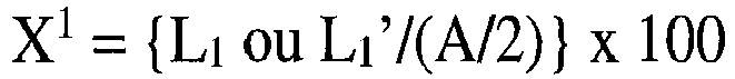 où X2 est calculé par la formule (2) :
 où, dans une droite arbitraire qui est parallèle à la seconde direction du séparateur (7) et fait de L2 ou de L2' le plus court, dans une vue de dessus, B est une longueur d'une partie où la zone d'électrode dans la ligne droite arbitraire et le séparateur (7) se chevauchent, et L2 et L2' sont des longueurs de portions où l'aire d'électrode et le séparateur (7) ne se chevauchent pas.
 - Procédé de production de l'élément de stockage au lithium non aqueux selon la revendication 1 ou 2, comprenant les étapes consistant à : faire réagir thermiquement le charbon actif avec le brai dans une atmosphère inerte, pour produire le matériau poreux composite dans lequel le charbon de brai est déposé sur la surface du charbon actif, dans lequel le charbon actif satisfait aux exigences suivantes :


pré-doper le matériau actif d'électrode négative avec des ions lithium en une quantité de 1 100 à 2 000 mAh/g sur la base du poids unitaire du matériau poreux composite.
Applications Claiming Priority (3)
| Application Number | Priority Date | Filing Date | Title |
|---|---|---|---|
| JP2012267592 | 2012-12-06 | ||
| JP2013136717 | 2013-06-28 | ||
| PCT/JP2013/082723 WO2014088074A1 (fr) | 2012-12-06 | 2013-12-05 | Élément de stockage au lithium non aqueux |
Publications (3)
| Publication Number | Publication Date |
|---|---|
| EP2930728A1 EP2930728A1 (fr) | 2015-10-14 |
| EP2930728A4 EP2930728A4 (fr) | 2015-11-18 |
| EP2930728B1 true EP2930728B1 (fr) | 2020-02-05 |
Family
ID=50883486
Family Applications (1)
| Application Number | Title | Priority Date | Filing Date |
|---|---|---|---|
| EP13860736.1A Active EP2930728B1 (fr) | 2012-12-06 | 2013-12-05 | Élément de stockage au lithium non aqueux |
Country Status (7)
| Country | Link |
|---|---|
| US (1) | US9748045B2 (fr) |
| EP (1) | EP2930728B1 (fr) |
| JP (1) | JP6373761B2 (fr) |
| KR (1) | KR101676214B1 (fr) |
| CN (1) | CN104823255B (fr) |
| TW (1) | TWI629817B (fr) |
| WO (1) | WO2014088074A1 (fr) |
Families Citing this family (19)
| Publication number | Priority date | Publication date | Assignee | Title |
|---|---|---|---|---|
| JP6029675B2 (ja) * | 2012-09-20 | 2016-11-24 | 旭化成株式会社 | リチウムイオンキャパシタ |
| KR101674842B1 (ko) * | 2012-10-01 | 2016-11-09 | 아사히 가세이 가부시키가이샤 | 축전 소자용 전극 및 비수계 리튬형 축전 소자 |
| CN106663549B (zh) | 2014-07-09 | 2018-10-12 | 旭化成株式会社 | 非水系锂型蓄电元件 |
| JP2016042502A (ja) * | 2014-08-14 | 2016-03-31 | 旭化成株式会社 | 非水系リチウム型蓄電素子用の負極 |
| JP2016042504A (ja) * | 2014-08-14 | 2016-03-31 | 旭化成株式会社 | 非水系リチウム型蓄電素子 |
| JP2016178126A (ja) * | 2015-03-18 | 2016-10-06 | 旭化成株式会社 | 非水系リチウム型蓄電素子 |
| JP6675146B2 (ja) * | 2015-03-18 | 2020-04-01 | 旭化成株式会社 | 非水系リチウム型蓄電素子 |
| JP6972087B2 (ja) * | 2015-03-18 | 2021-11-24 | 旭化成株式会社 | 非水系リチウム型蓄電素子 |
| CN111415821B (zh) | 2016-01-22 | 2022-06-07 | 旭化成株式会社 | 非水系锂蓄电元件的制造方法 |
| CN108028138B (zh) | 2016-01-22 | 2019-05-03 | 旭化成株式会社 | 正极前体 |
| CN110391094B (zh) * | 2016-01-22 | 2021-10-12 | 旭化成株式会社 | 非水系锂型蓄电元件 |
| CN108475586B (zh) | 2016-01-22 | 2019-08-02 | 旭化成株式会社 | 非水系锂蓄电元件 |
| CN108604504B (zh) | 2016-01-22 | 2019-09-10 | 旭化成株式会社 | 非水系锂型蓄电元件 |
| TWI628680B (zh) * | 2016-01-22 | 2018-07-01 | 旭化成股份有限公司 | 非水系鋰型蓄電元件 |
| JP7061759B2 (ja) * | 2016-11-11 | 2022-05-02 | 積水化学工業株式会社 | 液体クロマトグラフィー用カラム充填剤の製造方法 |
| JP6582276B2 (ja) * | 2017-11-07 | 2019-10-02 | 株式会社Aventino | 頭部画像評価装置 |
| JP6933590B2 (ja) * | 2018-02-22 | 2021-09-08 | 日産自動車株式会社 | 負極活物質のプレドープ方法、負極の製造方法、及び蓄電デバイスの製造方法 |
| DE112019000405T5 (de) * | 2018-03-05 | 2020-10-22 | Robert Bosch Gmbh | Schmelzextrudierte feststoffbatteriekomponenten |
| JP6876883B1 (ja) * | 2019-09-25 | 2021-05-26 | 積水化学工業株式会社 | 蓄電素子及び蓄電素子の製造方法 |
Citations (1)
| Publication number | Priority date | Publication date | Assignee | Title |
|---|---|---|---|---|
| EP2466670A1 (fr) * | 2009-07-31 | 2012-06-20 | Dow Corning Toray Co., Ltd. | Matériau actif pour électrode, électrode et dispositif de stockage d'électricité |
Family Cites Families (19)
| Publication number | Priority date | Publication date | Assignee | Title |
|---|---|---|---|---|
| JPH08107048A (ja) | 1994-08-12 | 1996-04-23 | Asahi Glass Co Ltd | 電気二重層キャパシタ |
| JP2000143225A (ja) * | 1998-11-06 | 2000-05-23 | Showa Denko Kk | 活性炭素材およびその製造法 |
| JP4497622B2 (ja) | 2000-02-17 | 2010-07-07 | 株式会社Kri | リチウム系二次電池用負極材料 |
| KR100807702B1 (ko) | 2000-11-17 | 2008-03-03 | 가부시끼가이샤 케이알아이 | 비수계 리튬 2차 전지 |
| FR2817387B1 (fr) * | 2000-11-27 | 2003-03-21 | Ceca Sa | Cellules de stockage d'energie a double couche electrochimique a haute densite d'energie et forte densite de puissance |
| JP2003217674A (ja) | 2002-01-25 | 2003-07-31 | Sony Corp | 非水電解質電池 |
| JP4105897B2 (ja) | 2002-05-27 | 2008-06-25 | 旭化成株式会社 | 負極材料、その製造方法及び蓄電素子 |
| JP2003346802A (ja) | 2002-05-27 | 2003-12-05 | Asahi Kasei Corp | 負極材料、その製造方法及び蓄電素子 |
| JP4833504B2 (ja) | 2002-11-22 | 2011-12-07 | 日立マクセルエナジー株式会社 | 電気化学キャパシタおよびそれを構成要素とするハイブリッド電源 |
| JP4809676B2 (ja) * | 2005-12-27 | 2011-11-09 | Jx日鉱日石エネルギー株式会社 | 石油コークス及びその製造方法 |
| WO2007137794A1 (fr) * | 2006-05-31 | 2007-12-06 | MAX-PLANCK-Gesellschaft zur Förderung der Wissenschaften e.V. | Électrode de carbone poreuse avec revÊtement polymÈre conducteur |
| JP5255569B2 (ja) * | 2007-11-16 | 2013-08-07 | 旭化成株式会社 | 非水系リチウム型蓄電素子 |
| JP5463144B2 (ja) * | 2007-11-16 | 2014-04-09 | 大阪瓦斯株式会社 | 非水系リチウム型蓄電素子用正極材料 |
| JP2010080419A (ja) * | 2008-08-28 | 2010-04-08 | Kuraray Co Ltd | 導電性シートおよび電極用シート |
| JP2010267878A (ja) * | 2009-05-15 | 2010-11-25 | Asahi Kasei Corp | 非水系リチウム型蓄電素子 |
| JP2010267875A (ja) | 2009-05-15 | 2010-11-25 | Asahi Kasei Corp | 非水系リチウム型蓄電素子用負極、及びそれを用いた非水系リチウム型蓄電素子 |
| WO2010150534A1 (fr) * | 2009-06-23 | 2010-12-29 | クラレケミカル株式会社 | Condensateur continu, procédé de production d'eau désionisée, et dispositif de production d'eau déionisée |
| JPWO2013168727A1 (ja) * | 2012-05-09 | 2016-01-07 | 信越化学工業株式会社 | リチウムのプリドープ方法、リチウムプリドープ電極、及び蓄電デバイス |
| JP6029675B2 (ja) * | 2012-09-20 | 2016-11-24 | 旭化成株式会社 | リチウムイオンキャパシタ |
-
2013
- 2013-12-05 WO PCT/JP2013/082723 patent/WO2014088074A1/fr active Application Filing
- 2013-12-05 TW TW102144669A patent/TWI629817B/zh active
- 2013-12-05 US US14/649,809 patent/US9748045B2/en active Active
- 2013-12-05 CN CN201380062986.9A patent/CN104823255B/zh active Active
- 2013-12-05 KR KR1020157012754A patent/KR101676214B1/ko active IP Right Grant
- 2013-12-05 EP EP13860736.1A patent/EP2930728B1/fr active Active
- 2013-12-05 JP JP2014551143A patent/JP6373761B2/ja active Active
Patent Citations (1)
| Publication number | Priority date | Publication date | Assignee | Title |
|---|---|---|---|---|
| EP2466670A1 (fr) * | 2009-07-31 | 2012-06-20 | Dow Corning Toray Co., Ltd. | Matériau actif pour électrode, électrode et dispositif de stockage d'électricité |
Also Published As
| Publication number | Publication date |
|---|---|
| CN104823255B (zh) | 2017-08-25 |
| JP6373761B2 (ja) | 2018-08-15 |
| WO2014088074A1 (fr) | 2014-06-12 |
| EP2930728A4 (fr) | 2015-11-18 |
| TWI629817B (zh) | 2018-07-11 |
| EP2930728A1 (fr) | 2015-10-14 |
| US9748045B2 (en) | 2017-08-29 |
| JPWO2014088074A1 (ja) | 2017-01-05 |
| KR101676214B1 (ko) | 2016-11-29 |
| CN104823255A (zh) | 2015-08-05 |
| KR20150070335A (ko) | 2015-06-24 |
| TW201429022A (zh) | 2014-07-16 |
| US20150311002A1 (en) | 2015-10-29 |
Similar Documents
| Publication | Publication Date | Title |
|---|---|---|
| EP2930728B1 (fr) | Élément de stockage au lithium non aqueux | |
| US9979010B2 (en) | Electrode for electrical storage element, and nonaqueous lithium electrical storage element | |
| EP2950319B1 (fr) | Condensateur lithium-ion | |
| US10236133B2 (en) | Lithium ion capacitor | |
| JP6223466B2 (ja) | リチウムイオンキャパシタ | |
| JP7042589B2 (ja) | 負極 | |
| JP7462066B2 (ja) | 非水系アルカリ金属蓄電素子および正極塗工液 | |
| JP6453560B2 (ja) | 非水系リチウム型蓄電素子用負極、及びそれを用いた非水系リチウム型蓄電素子 | |
| JP2018056435A (ja) | 非水系リチウム型蓄電素子 | |
| JP2018014398A (ja) | 非水系リチウム蓄電素子 | |
| JP2018061020A (ja) | 非水系リチウム型蓄電素子 | |
| JP2018056434A (ja) | 非水系リチウム型蓄電素子 | |
| JP2018056401A (ja) | 非水系リチウム型蓄電素子 |
Legal Events
| Date | Code | Title | Description |
|---|---|---|---|
| PUAI | Public reference made under article 153(3) epc to a published international application that has entered the european phase |
Free format text: ORIGINAL CODE: 0009012 |
|
| 17P | Request for examination filed |
Effective date: 20150605 |
|
| AK | Designated contracting states |
Kind code of ref document: A1 Designated state(s): AL AT BE BG CH CY CZ DE DK EE ES FI FR GB GR HR HU IE IS IT LI LT LU LV MC MK MT NL NO PL PT RO RS SE SI SK SM TR |
|
| AX | Request for extension of the european patent |
Extension state: BA ME |
|
| RA4 | Supplementary search report drawn up and despatched (corrected) |
Effective date: 20151020 |
|
| RIC1 | Information provided on ipc code assigned before grant |
Ipc: H01M 4/587 20100101ALI20151014BHEP Ipc: H01G 11/34 20130101ALI20151014BHEP Ipc: H01M 10/0566 20100101ALI20151014BHEP Ipc: H01M 10/052 20100101ALI20151014BHEP Ipc: H01G 11/24 20130101AFI20151014BHEP Ipc: H01M 10/058 20100101ALI20151014BHEP Ipc: H01G 11/06 20130101ALI20151014BHEP Ipc: H01M 4/38 20060101ALI20151014BHEP |
|
| 17Q | First examination report despatched |
Effective date: 20151028 |
|
| DAX | Request for extension of the european patent (deleted) | ||
| STAA | Information on the status of an ep patent application or granted ep patent |
Free format text: STATUS: EXAMINATION IS IN PROGRESS |
|
| GRAP | Despatch of communication of intention to grant a patent |
Free format text: ORIGINAL CODE: EPIDOSNIGR1 |
|
| STAA | Information on the status of an ep patent application or granted ep patent |
Free format text: STATUS: GRANT OF PATENT IS INTENDED |
|
| INTG | Intention to grant announced |
Effective date: 20190628 |
|
| GRAS | Grant fee paid |
Free format text: ORIGINAL CODE: EPIDOSNIGR3 |
|
| RAP1 | Party data changed (applicant data changed or rights of an application transferred) |
Owner name: ASAHI KASEI KABUSHIKI KAISHA |
|
| GRAA | (expected) grant |
Free format text: ORIGINAL CODE: 0009210 |
|
| STAA | Information on the status of an ep patent application or granted ep patent |
Free format text: STATUS: THE PATENT HAS BEEN GRANTED |
|
| AK | Designated contracting states |
Kind code of ref document: B1 Designated state(s): AL AT BE BG CH CY CZ DE DK EE ES FI FR GB GR HR HU IE IS IT LI LT LU LV MC MK MT NL NO PL PT RO RS SE SI SK SM TR |
|
| REG | Reference to a national code |
Ref country code: GB Ref legal event code: FG4D |
|
| REG | Reference to a national code |
Ref country code: AT Ref legal event code: REF Ref document number: 1230458 Country of ref document: AT Kind code of ref document: T Effective date: 20200215 |
|
| REG | Reference to a national code |
Ref country code: DE Ref legal event code: R096 Ref document number: 602013065546 Country of ref document: DE |
|
| REG | Reference to a national code |
Ref country code: IE Ref legal event code: FG4D |
|
| REG | Reference to a national code |
Ref country code: CH Ref legal event code: EP |
|
| REG | Reference to a national code |
Ref country code: NL Ref legal event code: MP Effective date: 20200205 |
|
| PG25 | Lapsed in a contracting state [announced via postgrant information from national office to epo] |
Ref country code: FI Free format text: LAPSE BECAUSE OF FAILURE TO SUBMIT A TRANSLATION OF THE DESCRIPTION OR TO PAY THE FEE WITHIN THE PRESCRIBED TIME-LIMIT Effective date: 20200205 Ref country code: RS Free format text: LAPSE BECAUSE OF FAILURE TO SUBMIT A TRANSLATION OF THE DESCRIPTION OR TO PAY THE FEE WITHIN THE PRESCRIBED TIME-LIMIT Effective date: 20200205 Ref country code: PT Free format text: LAPSE BECAUSE OF FAILURE TO SUBMIT A TRANSLATION OF THE DESCRIPTION OR TO PAY THE FEE WITHIN THE PRESCRIBED TIME-LIMIT Effective date: 20200628 Ref country code: NO Free format text: LAPSE BECAUSE OF FAILURE TO SUBMIT A TRANSLATION OF THE DESCRIPTION OR TO PAY THE FEE WITHIN THE PRESCRIBED TIME-LIMIT Effective date: 20200505 |
|
| REG | Reference to a national code |
Ref country code: LT Ref legal event code: MG4D |
|
| PG25 | Lapsed in a contracting state [announced via postgrant information from national office to epo] |
Ref country code: IS Free format text: LAPSE BECAUSE OF FAILURE TO SUBMIT A TRANSLATION OF THE DESCRIPTION OR TO PAY THE FEE WITHIN THE PRESCRIBED TIME-LIMIT Effective date: 20200605 Ref country code: SE Free format text: LAPSE BECAUSE OF FAILURE TO SUBMIT A TRANSLATION OF THE DESCRIPTION OR TO PAY THE FEE WITHIN THE PRESCRIBED TIME-LIMIT Effective date: 20200205 Ref country code: LV Free format text: LAPSE BECAUSE OF FAILURE TO SUBMIT A TRANSLATION OF THE DESCRIPTION OR TO PAY THE FEE WITHIN THE PRESCRIBED TIME-LIMIT Effective date: 20200205 Ref country code: BG Free format text: LAPSE BECAUSE OF FAILURE TO SUBMIT A TRANSLATION OF THE DESCRIPTION OR TO PAY THE FEE WITHIN THE PRESCRIBED TIME-LIMIT Effective date: 20200505 Ref country code: GR Free format text: LAPSE BECAUSE OF FAILURE TO SUBMIT A TRANSLATION OF THE DESCRIPTION OR TO PAY THE FEE WITHIN THE PRESCRIBED TIME-LIMIT Effective date: 20200506 Ref country code: HR Free format text: LAPSE BECAUSE OF FAILURE TO SUBMIT A TRANSLATION OF THE DESCRIPTION OR TO PAY THE FEE WITHIN THE PRESCRIBED TIME-LIMIT Effective date: 20200205 |
|
| PG25 | Lapsed in a contracting state [announced via postgrant information from national office to epo] |
Ref country code: NL Free format text: LAPSE BECAUSE OF FAILURE TO SUBMIT A TRANSLATION OF THE DESCRIPTION OR TO PAY THE FEE WITHIN THE PRESCRIBED TIME-LIMIT Effective date: 20200205 |
|
| PG25 | Lapsed in a contracting state [announced via postgrant information from national office to epo] |
Ref country code: EE Free format text: LAPSE BECAUSE OF FAILURE TO SUBMIT A TRANSLATION OF THE DESCRIPTION OR TO PAY THE FEE WITHIN THE PRESCRIBED TIME-LIMIT Effective date: 20200205 Ref country code: RO Free format text: LAPSE BECAUSE OF FAILURE TO SUBMIT A TRANSLATION OF THE DESCRIPTION OR TO PAY THE FEE WITHIN THE PRESCRIBED TIME-LIMIT Effective date: 20200205 Ref country code: SM Free format text: LAPSE BECAUSE OF FAILURE TO SUBMIT A TRANSLATION OF THE DESCRIPTION OR TO PAY THE FEE WITHIN THE PRESCRIBED TIME-LIMIT Effective date: 20200205 Ref country code: ES Free format text: LAPSE BECAUSE OF FAILURE TO SUBMIT A TRANSLATION OF THE DESCRIPTION OR TO PAY THE FEE WITHIN THE PRESCRIBED TIME-LIMIT Effective date: 20200205 Ref country code: LT Free format text: LAPSE BECAUSE OF FAILURE TO SUBMIT A TRANSLATION OF THE DESCRIPTION OR TO PAY THE FEE WITHIN THE PRESCRIBED TIME-LIMIT Effective date: 20200205 Ref country code: DK Free format text: LAPSE BECAUSE OF FAILURE TO SUBMIT A TRANSLATION OF THE DESCRIPTION OR TO PAY THE FEE WITHIN THE PRESCRIBED TIME-LIMIT Effective date: 20200205 Ref country code: SK Free format text: LAPSE BECAUSE OF FAILURE TO SUBMIT A TRANSLATION OF THE DESCRIPTION OR TO PAY THE FEE WITHIN THE PRESCRIBED TIME-LIMIT Effective date: 20200205 Ref country code: CZ Free format text: LAPSE BECAUSE OF FAILURE TO SUBMIT A TRANSLATION OF THE DESCRIPTION OR TO PAY THE FEE WITHIN THE PRESCRIBED TIME-LIMIT Effective date: 20200205 |
|
| REG | Reference to a national code |
Ref country code: DE Ref legal event code: R097 Ref document number: 602013065546 Country of ref document: DE |
|
| REG | Reference to a national code |
Ref country code: AT Ref legal event code: MK05 Ref document number: 1230458 Country of ref document: AT Kind code of ref document: T Effective date: 20200205 |
|
| PLBE | No opposition filed within time limit |
Free format text: ORIGINAL CODE: 0009261 |
|
| STAA | Information on the status of an ep patent application or granted ep patent |
Free format text: STATUS: NO OPPOSITION FILED WITHIN TIME LIMIT |
|
| 26N | No opposition filed |
Effective date: 20201106 |
|
| PG25 | Lapsed in a contracting state [announced via postgrant information from national office to epo] |
Ref country code: IT Free format text: LAPSE BECAUSE OF FAILURE TO SUBMIT A TRANSLATION OF THE DESCRIPTION OR TO PAY THE FEE WITHIN THE PRESCRIBED TIME-LIMIT Effective date: 20200205 Ref country code: AT Free format text: LAPSE BECAUSE OF FAILURE TO SUBMIT A TRANSLATION OF THE DESCRIPTION OR TO PAY THE FEE WITHIN THE PRESCRIBED TIME-LIMIT Effective date: 20200205 |
|
| PG25 | Lapsed in a contracting state [announced via postgrant information from national office to epo] |
Ref country code: SI Free format text: LAPSE BECAUSE OF FAILURE TO SUBMIT A TRANSLATION OF THE DESCRIPTION OR TO PAY THE FEE WITHIN THE PRESCRIBED TIME-LIMIT Effective date: 20200205 Ref country code: PL Free format text: LAPSE BECAUSE OF FAILURE TO SUBMIT A TRANSLATION OF THE DESCRIPTION OR TO PAY THE FEE WITHIN THE PRESCRIBED TIME-LIMIT Effective date: 20200205 |
|
| REG | Reference to a national code |
Ref country code: CH Ref legal event code: PL |
|
| GBPC | Gb: european patent ceased through non-payment of renewal fee |
Effective date: 20201205 |
|
| PG25 | Lapsed in a contracting state [announced via postgrant information from national office to epo] |
Ref country code: MC Free format text: LAPSE BECAUSE OF FAILURE TO SUBMIT A TRANSLATION OF THE DESCRIPTION OR TO PAY THE FEE WITHIN THE PRESCRIBED TIME-LIMIT Effective date: 20200205 |
|
| REG | Reference to a national code |
Ref country code: BE Ref legal event code: MM Effective date: 20201231 |
|
| PG25 | Lapsed in a contracting state [announced via postgrant information from national office to epo] |
Ref country code: FR Free format text: LAPSE BECAUSE OF NON-PAYMENT OF DUE FEES Effective date: 20201231 Ref country code: LU Free format text: LAPSE BECAUSE OF NON-PAYMENT OF DUE FEES Effective date: 20201205 Ref country code: IE Free format text: LAPSE BECAUSE OF NON-PAYMENT OF DUE FEES Effective date: 20201205 |
|
| PG25 | Lapsed in a contracting state [announced via postgrant information from national office to epo] |
Ref country code: LI Free format text: LAPSE BECAUSE OF NON-PAYMENT OF DUE FEES Effective date: 20201231 Ref country code: CH Free format text: LAPSE BECAUSE OF NON-PAYMENT OF DUE FEES Effective date: 20201231 Ref country code: GB Free format text: LAPSE BECAUSE OF NON-PAYMENT OF DUE FEES Effective date: 20201205 |
|
| PG25 | Lapsed in a contracting state [announced via postgrant information from national office to epo] |
Ref country code: TR Free format text: LAPSE BECAUSE OF FAILURE TO SUBMIT A TRANSLATION OF THE DESCRIPTION OR TO PAY THE FEE WITHIN THE PRESCRIBED TIME-LIMIT Effective date: 20200205 Ref country code: MT Free format text: LAPSE BECAUSE OF FAILURE TO SUBMIT A TRANSLATION OF THE DESCRIPTION OR TO PAY THE FEE WITHIN THE PRESCRIBED TIME-LIMIT Effective date: 20200205 Ref country code: CY Free format text: LAPSE BECAUSE OF FAILURE TO SUBMIT A TRANSLATION OF THE DESCRIPTION OR TO PAY THE FEE WITHIN THE PRESCRIBED TIME-LIMIT Effective date: 20200205 |
|
| PG25 | Lapsed in a contracting state [announced via postgrant information from national office to epo] |
Ref country code: MK Free format text: LAPSE BECAUSE OF FAILURE TO SUBMIT A TRANSLATION OF THE DESCRIPTION OR TO PAY THE FEE WITHIN THE PRESCRIBED TIME-LIMIT Effective date: 20200205 Ref country code: AL Free format text: LAPSE BECAUSE OF FAILURE TO SUBMIT A TRANSLATION OF THE DESCRIPTION OR TO PAY THE FEE WITHIN THE PRESCRIBED TIME-LIMIT Effective date: 20200205 |
|
| PG25 | Lapsed in a contracting state [announced via postgrant information from national office to epo] |
Ref country code: BE Free format text: LAPSE BECAUSE OF NON-PAYMENT OF DUE FEES Effective date: 20201231 |
|
| P01 | Opt-out of the competence of the unified patent court (upc) registered |
Effective date: 20230515 |
|
| PGFP | Annual fee paid to national office [announced via postgrant information from national office to epo] |
Ref country code: DE Payment date: 20231031 Year of fee payment: 11 |