EP2919993B2 - Überwachungssystem für die ausrichtung von druckwerken einer reihendruckmaschine - Google Patents
Überwachungssystem für die ausrichtung von druckwerken einer reihendruckmaschine Download PDFInfo
- Publication number
- EP2919993B2 EP2919993B2 EP13771100.8A EP13771100A EP2919993B2 EP 2919993 B2 EP2919993 B2 EP 2919993B2 EP 13771100 A EP13771100 A EP 13771100A EP 2919993 B2 EP2919993 B2 EP 2919993B2
- Authority
- EP
- European Patent Office
- Prior art keywords
- printing
- unit
- offset
- sensor unit
- print medium
- Prior art date
- Legal status (The legal status is an assumption and is not a legal conclusion. Google has not performed a legal analysis and makes no representation as to the accuracy of the status listed.)
- Active
Links
Images


Classifications
-
- B—PERFORMING OPERATIONS; TRANSPORTING
- B41—PRINTING; LINING MACHINES; TYPEWRITERS; STAMPS
- B41F—PRINTING MACHINES OR PRESSES
- B41F33/00—Indicating, counting, warning, control or safety devices
- B41F33/0081—Devices for scanning register marks
-
- B—PERFORMING OPERATIONS; TRANSPORTING
- B41—PRINTING; LINING MACHINES; TYPEWRITERS; STAMPS
- B41P—INDEXING SCHEME RELATING TO PRINTING, LINING MACHINES, TYPEWRITERS, AND TO STAMPS
- B41P2213/00—Arrangements for actuating or driving printing presses; Auxiliary devices or processes
- B41P2213/90—Register control
-
- B—PERFORMING OPERATIONS; TRANSPORTING
- B41—PRINTING; LINING MACHINES; TYPEWRITERS; STAMPS
- B41P—INDEXING SCHEME RELATING TO PRINTING, LINING MACHINES, TYPEWRITERS, AND TO STAMPS
- B41P2233/00—Arrangements for the operation of printing presses
- B41P2233/50—Marks on printed material
-
- B—PERFORMING OPERATIONS; TRANSPORTING
- B41—PRINTING; LINING MACHINES; TYPEWRITERS; STAMPS
- B41P—INDEXING SCHEME RELATING TO PRINTING, LINING MACHINES, TYPEWRITERS, AND TO STAMPS
- B41P2233/00—Arrangements for the operation of printing presses
- B41P2233/50—Marks on printed material
- B41P2233/52—Marks on printed material for registering
Definitions
- the present invention relates to a monitoring system for the alignment of printing units of a series printing machine, a correspondingly equipped series printing machine and a monitoring method for the alignment of printing units of a series printing machine.
- printing units are arranged in a row in the form of a series printing machine.
- the supply to the individual printing units takes place successively, so that there is a corresponding free conveying length of the printing medium between the individual printing units, which are responsible for different colors.
- the print medium is often made available by a paper roll and unrolled there and is in the form of a web.
- so-called printing markers are used.
- the print markers are part of the print image or are printed on the print medium on the side or on the edge of the print image.
- the exact position of the print image on the print medium can thus be determined by appropriate sensors, in particular sensor devices with sensor units for each printing unit. On the basis of this detection, the associated printing unit settings are aligned, that is to say in particular a mechanical displacement of the individual printing rollers in their axial direction.
- a disadvantage of known row printing machines and corresponding monitoring systems with sensor devices is that they are limited in terms of their detection width in order to be able to provide the necessary high speed with regard to detection at high printing speeds.
- different properties of the print medium may occur due to batch differences. These are in particular changes in the mechanical stability, preferably based on the tensile strength or the modulus of elasticity of the pressure medium. This variation can lead to so-called sheet travel. This means that the two lateral edges of the printing medium can withstand the pull applied by the printing machine to different degrees.
- a corresponding printing medium thus moves laterally, that is to say transversely to the conveying direction, along the respective printing units.
- This displacement error or this offset increases over the course of the entire in-line printing press, that is to say from printing unit to printing unit. Compared to small misalignments in the course of a batch in a feed roller, these are very large differences in the range of several millimeters. Due to the relatively small detection areas of the sensor unit, it can happen that the large misalignment when the roll is changed means that the print markers can no longer be recognized. In such a case, the machine stops and an operator of this in-line printing machine must manually readjust the corresponding offset data and accordingly align the printing units manually. By stopping the machine, however, at least the length section of the printing medium that is in the machine at this time arises as rejects or as so-called waste.
- the DE 10 2006 030 170 A1 also describes a generic system and a generic method.
- a monitoring system serves to align printing units of a series printing machine, in particular a gravure printing machine.
- Such a monitoring system has a sensor device with at least one sensor unit for each printing unit. These are designed to recognize the position of a print mark on the print medium. This information about the position of the print marker or print mark is used for the subsequent alignment of the printing unit.
- a monitoring system according to the invention is characterized in that at least one sensor unit arranged downstream of a first sensor unit can be moved transversely to the conveying direction of the pressure medium. The results The monitoring by the sensor device is used for the axial alignment of the respective printing unit.
- a controlled system is made available which adapts the respective printing unit to the recognized offset of the printing medium.
- the adaptation that is to say the coupling between the alignment of the respective printing unit and the sensor device, is preferably carried out electronically, in particular digitally.
- each sensor unit can be adjusted here.
- This relates in particular to so-called subordinate sensor units, in other words not the first sensor unit.
- This mobility is in particular translational mobility. Movability transverse to the conveying direction is to be understood in particular to mean movement essentially perpendicular to the conveying direction.
- an automatic or at least semi-automatic adaptation of the downstream sensor units can now be set to a high offset. If the first sensor unit detects a first offset in the first printing unit, which is in particular outside a standard offset in continuous operation, this offset can be used for repositioning the downstream movable sensor units. In the event of a roll change, that is to say if a significantly increased offset is to be expected, such a monitoring system can be put into a special programming so that an automated movement takes place transversely to the conveying direction of the downstream sensor units based on the recognized offset of the first sensor unit. This can reduce the likelihood that the downstream sensor units will no longer recognize the print markers of the preceding printing units.
- the downstream sensor units are moved in the direction of the offset, so that the sensor unit is in a suitable monitoring position at the time at which the offset printing mark is located in the downstream printing unit. Accordingly, the likelihood of the alignment of the printing units being made available by the information from the individual sensor units also in the case of a roll change is significantly increased in comparison with static sensor units in known monitoring systems. Due to the fact that the printing units can be aligned quickly and easily in this way even in the case of roll change situations, the roll change can be carried out in particular at a consistently high printing speed and above all without stopping and the production of rejects with regard to the printing medium.
- Print media that can be stored on a roll are particularly suitable as the print medium in the sense of the present invention. It can be z. B. paper or plastic, in particular PE or PET. Of course, the printing medium can be of one or more layers or of one or more layers.
- the sensor unit can be designed in a wide variety of ways for the recognition of the print mark. In particular, however, it has a possibility of generating a light spot and the associated evaluation optics in order to be able to carry out a corresponding position determination of the print mark on the print medium at a sufficiently high speed.
- the sensor unit also has associated control electronics and cabling, e.g. B. for the power supply or signal transmission.
- the signal forwarding can of course also take place wirelessly in order to make the mobility of the sensor unit even easier.
- the at least one movable sensor unit can be moved in translation by means of an actuator system, in particular with an electric motor.
- an electric motor e.g. B. the use of an air motor in the context of the present invention is also conceivable.
- An actuator system is used for the automatic or semi-automatic mobility of the sensor unit.
- a gear transmission can be made available in the form of a spindle gear in order to be able to ensure that the sensor unit can be adjusted precisely by means of the actuators.
- An electric motor can represent a particularly inexpensive and simple embodiment of such an actuator system.
- other transmission variants are also possible for the transmission of the force to the sensor unit for its translatory movement.
- Movable cable sleeves can be provided as a cable guide to the movable sensor unit.
- the sensor device and / or each sensor unit can have a corresponding control unit in order to carry out a monitoring method in whole or in part, as will be explained in more detail later.
- the at least one movable sensor unit can be moved along a guide, in particular along a guide rail.
- the guidance serves to predefine the movement path of the sensor unit.
- it is a translational guide or guide rail.
- a guide rail serves z. B. the sliding bearing movement of the sensor unit along this guide rail.
- the mechanical design of such a guide can of course be adjustable, so that preferably different large movement paths can be realized for each sensor unit.
- the movement of the sensor unit along Such a guide can also be designed as a traversing movement.
- another actuator in order to generate a movement of the sensor unit along the guide, in addition to the actuator system already described, e.g. B. in the form of an electric motor, another actuator, in particular lever kinematics, are used.
- the at least one movable sensor unit is designed to be movable as a function of an offset which has been recognized by the sensor unit arranged upstream of the pressure curve.
- This enables the movable sensor unit to be pre-positioned.
- This advance movement is based on a signal-communicating connection between at least two sensor units that are separate from one another, so that the detected offset of a pre-arranged sensor unit can be transmitted to the downstream movable sensor unit.
- This can be done in a simple control manner or in a closed control loop.
- the sensor unit and / or the sensor device can have a corresponding control unit for the execution of this signal communication or the corresponding control of the movement of the sensor unit.
- a preparation for the expected minimum offset takes place, so that, as has already been explained, an increase in the probability of the detection of the offset print mark is achieved.
- the at least one movable sensor unit has a possible movement path which is formed in the range of approximately ⁇ 2% based on the width of the printing medium transversely to the conveying direction. This specifies a possibility of a movement path that can compensate for a sufficient mobility with respect to the expected offset.
- printing widths of the printing medium come e.g. B. Values in the range between approx. 1000 and approx. 1500 mm in question. Approx. ⁇ 10 mm to approximately ⁇ 20 mm are particularly advantageous as possible movement paths.
- the individual movable sensor units are arranged in the center of the corresponding movement path.
- a control unit is provided for the execution of a monitoring method according to the invention which will be explained later. Accordingly, a monitoring system according to the invention has the same advantages as will be explained later with reference to a monitoring method according to the invention.
- the present invention also relates to a series printing machine with at least two printing units arranged in series for printing on a printing medium.
- a series printing machine according to the invention is characterized in that at least one monitoring device according to the present invention is provided for the alignment of the printing units. Accordingly, a series printing machine according to the invention brings with it the same advantages as have been explained in detail with reference to a monitoring system according to the invention.
- a monitoring method according to the invention is therefore used in particular in a series printing machine according to the invention, so that the same advantages can be achieved as have been explained in detail with reference to a series printing machine according to the invention and with reference to a monitoring system according to the invention.
- the subsequent sensor unit of the second printing unit can be pre-positioned. If an offset is detected in the first printing unit, the second sensor unit of the second printing unit can already be displaced in the direction of the recognized offset in preparation for this offset.
- This monitoring procedure is in particular a special procedure which is used when the print medium is changed. With high probabilities of delay, e.g. B. when generating a sheet run, the printing medium can be ensured in this way that even with a relatively large offset on the first printing unit, the other printing units are prepared for this large offset and can also recognize the print mark.
- This pre-positioning increases the security of the monitoring and thus reduces the likelihood of a machine stop. As has already been explained, this can significantly reduce the machine stop and the corresponding waste or so-called waste.
- An advantage can also be achieved if, in a monitoring method according to the invention, after detecting the offset of a printing mark on the printing medium in a first printing unit, all sensor units arranged downstream in the course of the printing transversely to the conveying direction of the printing medium in the direction of the detected Offset are moved. In a series printing machine with a large number of printing units, sensor units of the third, fourth and subsequent printing units can accordingly also be moved accordingly from the first detection of an offset on the first printing unit. This means that even large offsets with correspondingly smaller servomotors or less powerful actuators with regard to the high printing speed can be moved sufficiently quickly through the pre-positioning. This allows a reduction in the cost and the necessary installation space of the individual sensor units and the associated actuators. It can also be ensured that the in-line printing press can be operated at full printing speed even in the case of roll change situations.
- a monitoring method can be developed in such a way that the movement of the sensor unit of the second printing unit takes place at least by the amount of the recognized offset of the printing mark on the first printing unit.
- the minimum path of movement along the movement path is also predefined in this way. The movement therefore takes place at least by the recognized offset. It can be assumed that the offset increases in the same direction over the course of the printing press, that is to say from printing unit to printing unit.
- the pre-positioning by at least the amount of the recognized offset for the following printing unit thus allows the minimum positioning of the at least further offset to be expected for this second printing unit.
- a larger travel path than the amount of the detected offset can also be used.
- This increase in movement can e.g. B. on further information, e.g. B. on stored mean values using statistical evaluation methods.
- the increased travel path setting on the basis of a corresponding function of the recognized offset is also conceivable.
- a further advantage can be achieved if, in a monitoring method according to the invention, a sensor unit of a third printing unit is moved transversely to the conveying direction of the printing medium by an amount which is composed of the recognized offset and the recognized residual offset. At the latest after the print mark has passed through the second printing unit, both the offset and the detected residual offset are known. Accordingly, an expected residual offset for the own printing unit can be determined for the further displacement movements of the movable sensor units via the residual offset. Thus, the movable sensor units of the following printing units can be moved beyond the amount of the detected offset. This enables the subsequent sensor units to be positioned even more precisely in advance.
- the movement of the sensor unit of the second printing unit in the direction of the detected offset also takes place when no printing mark is detected on the second printing unit.
- the situation can arise that the print mark is not recognized by the sensor unit despite the pre-positioning on the second printing unit.
- the printing press does not necessarily have to be stopped completely here. Rather, the further movement of the sensor unit on the second printing unit can compensate for this deficiency again by means of the information about the direction of the detected offset and, after a short movement phase, can also recognize the printing mark on the second printing unit again.
- a monitoring method according to the invention a complete stop of the in-line printing machine and the corresponding rejects can be avoided even if the possibility of recognizing the print mark is lost.
- a monitoring method according to the invention can be developed in such a way that it is carried out as a special program for the duration of a roll change of the printing medium. Accordingly, other parameters for the positioning or movement of the individual sensor units can be used as the normal program.
- the measuring motor system ie the alignment of a light point and the evaluation using the corresponding optics, can differ from the normal program in the special program according to the present invention.
- the duration of the roll change is at least the length of time which is necessary to have the printing medium of the newly used roll completely within the in-line printing press.
- the special program is ended after the roll change has ended, in particular after a predetermined print length.
- a given print length can e.g. B. be one to two machine lengths of the print medium.
- the normal program already explained can continue to control or regulate. In particular, when returning to the normal program, the sensor devices or the sensor units remain at the positions at which they were or were positioned at the end of the special program of the monitoring method.
- the time offset to the first printing unit is taken into account in the sensor unit of the second printing unit.
- the respective downstream sensor unit remains in its previous position until, for example, the new material has reached this sensor unit when a roll is changed. The previous material will usually not yet have the sheet run. Thus, premature movement of the respective sensor unit could lead to the loss of the possibility of recognizing these print marks.
- the ratio of the printing length between the two printing units and the printing speed is in particular formed as a relation for the time offset.
- the time required for the movement of the sensor unit can also be taken into account.
- the downstream sensor units are moved around the detected offset with a time offset, in particular at precisely the right time, and are thus not only pre-positioned locally but also in time.
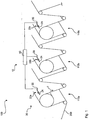
- a row printing machine 100 is shown schematically. Three printing units 110a, 110b and 110c are shown here.
- the pressure medium 200 is guided and conveyed along the conveying direction F via a multiplicity of deflecting rollers and pressure rollers.
- FIG. 1 it can be seen that this embodiment of the in-line printing press 100 is designed with a monitoring system 10 according to the invention.
- This has a control unit 40, which is connected in a signal-communicating manner to a respective sensor unit 22a, 22b and 22c of a sensor device 20.
- the sensor units 22a, 22b and 22c are each assigned to a printing group 100a, 100b and 100c.
- the individual sensor units 22a, 22b and 22c are essentially of identical design and have a guide 24 for translatory movement transverse to the conveying direction F.
- an actuator system 30 is provided in the form of an electric motor.
- the 2a to 2c show a possibility of carrying out a monitoring method according to the invention. They are shown schematically in particular according to the embodiment of a series printing machine 100 Fig. 1 based. All three are like that 2a to 2c to see a situation with three sensor units 22a, 22b and 22c, which correlate with associated printing units 100a, 100b and 100c (not shown). It can also be seen that a printing mark 210 is applied to a printing medium 200 (not shown in more detail).
- the method begins at the time of a roll change of the print medium 200. Due to the roll change and corresponding change due to batch differences in the elastic modulus of the print medium 200, the sensor unit 22a detects an offset V on the first printing unit 110a. When this offset V is determined, the two further sensor units 22b and 22c move automatically and automatically in the direction of this offset V and, in one embodiment of this monitoring method, even exactly by the amount of the offset V. The result shows Fig. 2b , so that the downstream sensor units 22b and 22c have already been pre-positioned by the offset V.
- the pre-positioning of the sensor unit 22b can now also be used to directly identify the residual offset R of the print mark 210.
- a movement of the third sensor unit 22c around this residual offset R now takes place. This can be carried out in an identical manner for further printing units, so that the loss of the possibility of recognizing the print mark 210 can be virtually excluded by the pre-positioning.
- Fig. 3 shows a possibility of how different print marks 210 can be arranged on the print medium 200. These have a straight edge in the direction of the conveying direction F at the beginning, that is to say at their upper end, and an oblique edge at their lower end. In this way, in addition to a positioning and alignment of the individual printing units 110a, 110b and 110c in the conveying direction F, an alignment transverse to the conveying direction F can also take place. About the relation between a light point of the sensor unit 22a and the oblique edge of the print mark 210 can this lateral offset V, which is the axial offset in relation to the respective printing unit, can be recognized. This determination result is used as an input variable for the controlled alignment of the respective printing group 110a, 110b and 110c.
- a separate print mark 210 can be applied to the printing medium for each individual printing unit 110a, 110b and 110c. Also recognizable in Fig. 3 is the freedom of movement along a movement path S for this sensor unit 22a. Here, a guide 24 in frame construction is provided, so that an even more precise pre-positioning along the movement path S is possible.
Landscapes
- Inking, Control Or Cleaning Of Printing Machines (AREA)
- Controlling Sheets Or Webs (AREA)
- Handling Of Sheets (AREA)
Description
- Die vorliegende Erfindung betrifft ein Überwachungssystem für die Ausrichtung von Druckwerken einer Reihendruckmaschine, eine entsprechend ausgestattete Reihendruckmaschine sowie ein Überwachungsverfahren für die Ausrichtung von Druckwerken einer Reihendruckmaschine.
- Es ist grundsätzlich bekannt, dass Druckwerke in einer Reihe in Form einer Reihendruckmaschine angeordnet sind. Dabei erfolgt die Zufuhr zu den einzelnen Druckwerken nacheinander, so dass zwischen den einzelnen Druckwerken, welche für jeweils unterschiedliche Farben verantwortlich sind, eine entsprechende freie Förderlänge des Druckmediums vorhanden ist. Das Druckmedium wird dabei häufig von einem Papierwickel zur Verfügung gestellt und dort abgerollt und ist bahnförmig ausgebildet. Um sicherzustellen, dass die einzelnen Farben der einzelnen Druckwerke auch registergenau zueinander auf dem Druckmedium aufgebracht werden, ist es bekannt, dass sogenannte Druckmarker verwendet werden. Die Druckmarker sind Teil des Druckbilds bzw. werden auf das Druckmedium seitlich bzw. am Rand des Druckbilds mit aufgedruckt. Damit kann durch entsprechende Sensorik, insbesondere durch Sensorvorrichtungen mit Sensoreinheiten für jedes Druckwerk, die exakte Position des Druckbilds auf dem Druckmedium bestimmt werden. Anhand dieses Erkennens erfolgt ein Ausrichten der zugehörigen Druckwerkeinstellungen, also insbesondere ein mechanisches Verschieben der einzelnen Druckwalzen in deren axialer Richtung.
- Nachteilhaft bei bekannten Reihendruckmaschinen sowie entsprechenden Überwachungssystemen mit Sensorvorrichtungen ist es, dass diese hinsichtlich ihrer Erkennungsbreite eingeschränkt sind, um die notwendige hohe Geschwindigkeit hinsichtlich der Erkennung bei hohen Druckgeschwindigkeiten zur Verfügung stellen zu können. Findet jedoch ein Medienwechsel bzw. bei gleichem Druckmedium der Zufuhrwechsel mit einer neuen Rolle statt, so kann es aufgrund von Chargenunterschieden zu unterschiedlichen Eigenschaften des Druckmediums kommen. Dies sind insbesondere Änderungen der mechanischen Stabilität, vorzugsweise bezogen auf die Zugfestigkeit bzw. das E-Modul des Druckmediums. Diese Variation kann zu sogenanntem Bogenlauf führen. Das bedeutet, dass die beiden seitlichen Kanten des Druckmediums unterschiedlich stark dem durch die Druckmaschine aufgebrachten Zug widerstehen können. Damit verschiebt sich ein entsprechendes Druckmedium seitlich, also quer zur Förderrichtung, entlang der jeweiligen Druckwerke. Diese Verschiebefehler bzw. dieser Versatz nimmt über den Verlauf der gesamten Reihendruckmaschine, also von Druckwerk zu Druckwerk zu. Dabei handelt es sich im Vergleich zu kleinen Versatzsituationen im Verlauf innerhalb einer Chargen in einer Zufuhrrolle um sehr große Unterschiede im Bereich von mehreren Millimetern. Aufgrund der relativ kleinen Erkennungsbereiche der Sensoreinheit kann es nun passieren, dass durch den großen Versatz beim Rollenwechsel keine Erkennung der Druckmarker mehr erfolgen kann. In einem solchen Fall stoppt die Maschine und ein Betriebsführer dieser Reihendruckmaschine muss manuell die entsprechenden Versatzdaten nachstellen und dementsprechend manuell die Druckwerke ausrichten. Durch das Stoppen der Maschine entsteht jedoch zumindest der zu diesem Zeitpunkt in der Maschine befindliche Längenabschnitt des Druckmediums als Ausschuss bzw. als sogenannte Makulatur. Auch wenn die Maschine nicht gestoppt wird, verschieben sich die Druckbilder der einzelnen Druckwerke zueinander in unzulässiger Weise. So kann zwar weiter gedruckt werden, jedoch wird zumindest ein Abschnitt des Druckmediums anschließend als Ausschuss entsorgt. Mit anderen Worten beinhaltet ein Rollenwechsel bei bekannten Überwachungssystemen für Reihendruckmaschinen häufig bzw. fast immer einen hohen Ausschuss durch das Stoppen der Maschine und das manuelle Neuausrichten. Auch entsteht hier ein Zeitverlust, der durch das Stoppen, Auswechseln und Neuanfahren der Reihendruckmaschine erforderlich wird.
- Die
DE 10 2006 030 170 A1 beschreibt ferner ein gattungsgemäßes System und ein gattungsgemäßes Verfahren. - Es ist Aufgabe der vorliegenden Erfindung, die voranstehend beschriebenen Nachteile zumindest teilweise zu beheben. Insbesondere ist es Aufgabe der vorliegenden Erfindung, ein Überwachungssystem für die Ausrichtung von Druckwerken einer Reihendruckmaschine, eine entsprechend ausgestattete Reihendruckmaschine sowie ein Überwachungsverfahren für die Ausrichtung von Druckwerken einer Reihendruckmaschine zur Verfügung zu stellen, welche in kostengünstiger und einfacher Weise Ausschuss reduzieren und insbesondere einen reibungslosen Rollenwechsel in der Zufuhr des Druckmediums ermöglichen.
- Voranstehende Aufgabe wird gelöst durch ein Überwachungssystem mit den Merkmalen des Anspruchs 1, eine Reihendruckmaschine mit den Merkmalen des Anspruchs 7 sowie ein Überwachungsverfahren mit den Merkmalen des Anspruchs 8. Weitere Merkmale und Details der Erfindung ergeben sich aus den Unteransprüchen, der Beschreibung und den Zeichnungen.
- Ein erfindungsgemäßes Überwachungssystem dient der Ausrichtung von Druckwerken einer Reihendruckmaschine, insbesondere einer Tiefdruckmaschine. Ein solches Überwachungssystem weist eine Sensorvorrichtung mit zumindest einer Sensoreinheit für jedes Druckwerk auf. Diese sind ausgebildet, um die Position einer Druckmarke auf dem Druckmedium zu erkennen. Für das nachfolgende Ausrichten des Druckwerks wird diese Information über die Position des Druckmarkers bzw. der Druckmarke verwendet. Ein erfindungsgemäßes Überwachungssystem zeichnet sich dadurch aus, dass wenigstens eine im Druckverlauf einer ersten Sensoreinheit nachgeordnete Sensoreinheit quer zur Förderrichtung des Druckmediums bewegbar ist. Die Ergebnisse der Überwachung durch die Sensorvorrichtung werden für die axiale Ausrichtung des jeweiligen Druckwerks eingesetzt. Mit anderen Worten wird eine Regelstrecke zur Verfügung gestellt, welche das jeweilige Druckwerk an den erkannten Versatz des Druckmediums anpasst. Die Anpassung, also die Koppelung zwischen dem Ausrichten des jeweiligen Druckwerks und der Sensorvorrichtung, erfolgt vorzugsweise in elektronischer, insbesondere in digitaler Weise.
- Im Gegensatz zu bekannten Überwachungssystemen kann hier eine Einstellbarkeit hinsichtlich des Überwachungsbereichs jeder Sensoreinheit erfolgen. Dies bezieht sich insbesondere auf sogenannte nachgeordnete Sensoreinheiten, also gerade nicht die erste Sensoreinheit. Diese Bewegbarkeit ist insbesondere eine translatorische Bewegbarkeit. Unter einer Bewegbarkeit quer zur Förderrichtung ist insbesondere ein Bewegen im Wesentlichen senkrecht zur Förderrichtung zu verstehen.
- Mit einem erfindungsgemäßen Überwachungssystem kann nun eine automatische oder zumindest halbautomatische Anpassung der nachgeordneten Sensoreinheiten auf einen hohen Versatz eingestellt werden. Wird von der ersten Sensoreinheit beim ersten Druckwerk ein erster Versatz festgestellt, welcher insbesondere außerhalb eines Normversatzes bei kontinuierlichem Betrieb liegt, kann dieser Versatz für eine Neupositionierung der nachgeordneten bewegbaren Sensoreinheiten verwendet werden. Im Falle eines Rollenwechsels, wenn also ein deutlich erhöhter Versatz zu erwarten ist, kann ein solches Überwachungssystem in eine Sonderprogrammierung versetzt werden, so dass automatisiert eine Bewegung quer zur Förderrichtung der nachgeordneten Sensoreinheiten basierend auf dem erkannten Versatz der ersten Sensoreinheit erfolgt. Damit kann die Wahrscheinlichkeit reduziert werden, dass die nachgeordneten Sensoreinheiten die Druckmarker der voranstehenden Druckwerke nicht mehr erkennen. Vielmehr erfolgt ein Vorabverschieben der nachgeordneten Sensoreinheiten in Richtung des Versatzes, so dass diese sich zu dem Zeitpunkt, zu welchem sich die versetzte Druckmarke in dem nachgeordneten Druckwerk befindet, sich die Sensoreinheit in einer dafür passenden Überwachungsposition eingefunden hat. Dementsprechend ist die Wahrscheinlichkeit auch im Rollenwechsel die Ausrichtung der Druckwerke durch die Informationen der einzelnen Sensoreinheiten zur Verfügung zu stellen, deutlich erhöht im Vergleich zu statischen Sensoreinheiten bei bekannten Überwachungssystemen. Aufgrund der Tatsache, dass auf diese Weise ein Ausrichten der Druckwerke auch bei Rollenwechselsituationen schnell und einfach erfolgen kann, kann insbesondere bei gleichbleibend hoher Druckgeschwindigkeit und vor allem ohne Stopp und die Produktion von Ausschuss hinsichtlich des Druckmediums der Rollenwechsel durchgeführt werden.
- Als Druckmedium im Sinne der vorliegenden Erfindung kommen insbesondere auf einer Rolle lagerbare Druckmedien in Frage. Dabei kann es sich z. B. um Papier oder Kunststoff, insbesondere PE oder PET, handeln. Selbstverständlich kann das Druckmedium ein- oder mehrlagig bzw. ein- oder mehrschichtig ausgebildet sein.
- Die Sensoreinheit kann für die Erkennung der Druckmarke in unterschiedlichster Weise ausgebildet sein. Insbesondere weist sie jedoch eine Erzeugungsmöglichkeit für einen Lichtpunkt sowie zugehöriger Auswerteoptik auf, um eine entsprechende Positionsbestimmung der Druckmarke auf dem Druckmedium mit ausreichend hoher Geschwindigkeit durchführen zu können. Selbstverständlich weist die Sensoreinheit neben der tatsächlichen Sensorelektronik auch zugehörige Steuerelektronik und Verkabelung, z. B. für die Stromversorgung oder die Signalweiterleitung auf. Dabei kann die Signalweiterleitung selbstverständlich auch drahtlos erfolgen, um die Bewegbarkeit der Sensoreinheit noch leichter zur Verfügung stellen zu können.
- Es kann von Vorteil sein, wenn bei einem erfindungsgemäßen Überwachungssystem die wenigstens eine bewegbare Sensoreinheit mittels einer Aktorik, insbesondere mit einem Elektromotor, translatorisch bewegbar ist. Alternativ zu einem Elektromotor ist z. B. auch die Verwendung eines Druckluftmotors im Rahmen der vorliegenden Erfindung denkbar. Eine Aktorik dient der automatischen bzw. halbautomatischen Bewegbarkeit der Sensoreinheit. Z. B. kann in Form eines Spindelgetriebes eine Getriebeübersetzung zur Verfügung gestellt werden, um eine positionsgenaue Verstellbarkeit der Sensoreinheit über die Aktorik gewährleisten zu können. Ein Elektromotor kann dabei eine besonders kostengünstige und einfache Ausführungsform einer solchen Aktorik darstellen. Selbstverständlich sind auch andere Getriebevarianten für die Übertragung der Kraft auf die Sensoreinheit zu deren translatorischer Bewegung möglich. Als Kabelführung zu der bewegbaren Sensoreinheit können bewegbare Kabelhüllen vorgesehen sein. Um eine entsprechende Ansteuerung der Bewegung zur Verfügung stellen zu können, kann die Sensorvorrichtung und/oder jede Sensoreinheit eine entsprechende Kontrolleinheit aufweisen, um ein Überwachungsverfahren ganz oder teilweise auszuführen, wie es später noch näher erläutert wird.
- Ein weiterer Vorteil ist es, wenn bei einem erfindungsgemäßen Überwachungssystem die wenigstens eine bewegbare Sensoreinheit entlang einer Führung, insbesondere entlang einer Führungsschiene, bewegbar ist. Die Führung dient der Vorabdefinition des Bewegungswegs der Sensoreinheit. Insbesondere handelt es sich um eine translatorische Führung bzw. Führungsschiene. Eine Führungsschiene dient z. B. der gleitgelagerten Bewegung der Sensoreinheit entlang dieser Führungsschiene. Die mechanische Ausbildung einer solchen Führung kann selbstverständlich verstellbar sein, so dass vorzugsweise auch unterschiedliche große Bewegungswege für jede Sensoreinheit realisiert werden können. Die Bewegung der Sensoreinheit entlang einer solchen Führung kann auch als traversierende Bewegung ausgebildet sein. Um eine Bewegung der Sensoreinheit entlang der Führung zu erzeugen, kann neben der bereits beschriebenen Aktorik, z. B. in Form eines Elektromotors, auch eine andere Aktorik, insbesondere eine Hebelkinematik, zum Einsatz kommen.
- Im Rahmen der vorliegenden Erfindung kann es weiter von Vorteil sein, wenn bei dem erfindungsgemäßen Überwachungssystem die wenigstens eine bewegbare Sensoreinheit in Abhängigkeit von einem Versatz bewegbar ausgebildet ist, welcher von der dem Druckverlauf vorangeordneten Sensoreinheit erkannt worden ist. Dies ermöglicht eine Vorabpositionierung der bewegbaren Sensoreinheit. Diese Vorabbewegung basiert auf einer signalkommunizierenden Verbindung zwischen zumindest zwei voneinander separaten Sensoreinheiten, so dass der erkannte Versatz einer vorangeordneten Sensoreinheit an die nachgeordnete bewegbare Sensoreinheit übermittelt werden kann. Dies kann in einfacher Steuerweise oder auch in einem geschlossenen Regelkreis geregelt erfolgen. Für die Ausführung dieser Signalkommunikation bzw. der entsprechenden Kontrolle der Bewegung der Sensoreinheit kann die Sensoreinheit und/oder die Sensorvorrichtung eine entsprechende Kontrolleinheit aufweisen. Es erfolgt also eine Vorbereitung auf den zu erwartenden Mindestversatz, so dass, wie bereits erläutert worden ist, eine Erhöhung der Wahrscheinlichkeit der Erkennung der versetzten Druckmarke erzielt wird.
- Ebenfalls vorteilhaft kann es sein, wenn bei einem erfindungsgemäßen Überwachungssystem die wenigstens eine bewegbare Sensoreinheit einen möglichen Bewegungsweg aufweist, welcher im Bereich von ca. ± 2% bezogen auf die Breite des Druckmediums quer zur Förderrichtung ausgebildet ist. Damit ist eine Möglichkeit eines Bewegungswegs angegeben, welcher eine ausreichende Bewegungsfähigkeit mit Bezug auf den zu erwartenden Versatz ausgleichen kann. Als Druckbreiten des Druckmediums kommen z. B. Werte im Bereich zwischen ca. 1000 und ca. 1500 mm in Frage. Als mögliche Bewegungswege sind insbesondere ca. ± 10 mm bis ca. ± 20 mm vorteilhaft. Zu Beginn einer neuen Rolle kann es vorteilhaft sein, wenn die einzelnen bewegbaren Sensoreinheiten mittig bezogen auf den entsprechenden Bewegungsweg angeordnet werden.
- Vorteilhaft ist es ebenfalls, wenn bei einem erfindungsgemäßen Überwachungssystem eine Kontrolleinheit für die Ausführung eines später noch erläuterten erfindungsgemäßen Überwachungsverfahrens vorgesehen ist. Dementsprechend bringt ein erfindungsgemäßes Überwachungssystem die gleichen Vorteile mit sich, wie sie später noch mit Bezug auf ein erfindungsgemäßes Überwachungsverfahren erläutert werden.
- Ebenfalls Gegenstand der vorliegenden Erfindung ist eine Reihendruckmaschine mit zumindest zwei in Reihe angeordneten Druckwerken für die Bedruckung eines Druckmediums. Eine erfindungsgemäße Reihendruckmaschine zeichnet sich dadurch aus, dass für die Ausrichtung der Druckwerke wenigstens eine Überwachungsvorrichtung gemäß der vorliegenden Erfindung vorgesehen ist. Dementsprechend bringt eine erfindungsgemäße Reihendruckmaschine die gleichen Vorteile mit sich, wie sie ausführlich mit Bezug auf ein erfindungsgemäßes Überwachungssystem erläutert worden sind.
- Gegenstand der vorliegenden Erfindung ist weiter ein Überwachungsverfahren für die Ausrichtung von Druckwerken einer Reihendruckmaschine, insbesondere gemäß der vorliegenden Erfindung, aufweisend die folgenden Schritte:
- Erkennen eines Versatzes einer Druckmarke auf dem Druckmedium bei einem ersten Druckwerk,
- Bewegen einer Sensoreinheit einer Sensorvorrichtung eines zweiten Druckwerks quer zur Förderrichtung des Druckmediums in Richtung des erkannten Versatzes,
- Erkennen eines Restversatzes der Druckmarke auf dem Druckmedium bei dem zweiten Druckwerk.
- Ein erfindungsgemäßes Überwachungsverfahren wird also insbesondere bei einer erfindungsgemäßen Reihendruckmaschine eingesetzt, so dass die gleichen Vorteile erzielt werden können, wie sie ausführlich mit Bezug auf eine erfindungsgemäße Reihendruckmaschine sowie mit Bezug auf ein erfindungsgemäßes Überwachungssystem erläutert worden sind.
- Im Sinne eines erfindungsgemäßen Überwachungsverfahrens kann eine Vorabpositionierung der nachfolgenden Sensoreinheit des zweiten Druckwerks erfolgen. Wird bei dem ersten Druckwerk ein Versatz erkannt, so kann auf diesen Versatz vorbereitend die zweite Sensoreinheit des zweiten Druckwerks bereits in Richtung des erkannten Versatzes verschoben werden. Dieses Überwachungsverfahren ist insbesondere ein Sonderverfahren, welches bei einem Rollenwechsel des Druckmediums eingesetzt wird. Bei hohen Verzugswahrscheinlichkeiten, z. B. beim Erzeugen eines Bogenlaufs, des Druckmediums kann auf diese Weise sichergestellt werden, dass auch bei einem relativ großen Versatz am ersten Druckwerk die weiteren Druckwerke auf diesen großen Versatz vorbereitet sind und die Druckmarke auch erkennen können. Diese Vorabpositionierung erhöht die Sicherheit der Überwachung und reduziert damit die Wahrscheinlichkeit eines Maschinenstopps. Damit können, wie bereits erläutert worden ist, der Stopp der Maschine und der entsprechende Ausschuss bzw. die sogenannte Makulatur deutlich reduziert werden.
- Ein Vorteil ist weiter erzielbar, wenn bei einem erfindungsgemäßen Überwachungsverfahren nach dem Erkennen des Versatzes einer Druckmarke auf dem Druckmedium bei einem ersten Druckwerk alle im Druckverlauf nachgeordneten Sensoreinheiten quer zur Förderrichtung des Druckmediums in Richtung des erkannten Versatzes bewegt werden. Bei einer Reihendruckmaschine mit einer Vielzahl von Druckwerken können dementsprechend auch Sensoreinheiten des dritten, vierten und der folgenden Druckwerke bereits ab der ersten Erkennung eines Versatzes am ersten Druckwerk entsprechend bewegt werden. Damit können auch große Versätze mit entsprechend kleineren Stellmotoren bzw. einer leistungsschwächeren Aktorik hinsichtlich der hohen Druckgeschwindigkeit ausreichend schnell durch die Vorabpositionierung bewegt werden. Damit kann eine Reduktion des Kostenaufwands und des notwendigen Bauraums der einzelnen Sensoreinheiten und der zugehörigen Aktorik erfolgen. Auch kann sichergestellt werden, dass auch bei Rollenwechselsituationen die Reihendruckmaschine mit voller Druckgeschwindigkeit betrieben werden kann.
- Ein erfindungsgemäßes Überwachungsverfahren lässt sich dahingehend weiterbilden, dass die Bewegung der Sensoreinheit des zweiten Druckwerks zumindest um den Betrag des erkannten Versatzes der Druckmarke am ersten Druckwerk erfolgt. Neben der Richtung der Vorabbewegung der bewegbaren Sensoreinheit wird also auf diese Weise auch der Mindestweg der Bewegung entlang des Bewegungswegs vordefiniert. Die Bewegung erfolgt also zumindest um den erkannten Versatz. Es kann nämlich davon ausgegangen werden, dass sich der Versatz über den Verlauf der Druckmaschine, also von Druckwerk zu Druckwerk in der gleichen Richtung erhöht. Die Vorabpositionierung um zumindest den Betrag des erkannten Versatzes für das folgende Druckwerk erlaubt somit die Mindestpositionierung des zumindest zu erwartenden weiteren Versatzes bei diesem zweiten Druckwerk. Selbstverständlich kann auch ein größerer Verfahrweg als der Betrag des erkannten Versatzes eingesetzt werden. Diese Vergrößerung der Bewegung kann z. B. auf weiteren Informationen, z. B. auf gespeicherten Mittelwerten über statistische Auswertverfahren erfolgen. Auch ist die vergrößerte Verfahrwegseinstellung auf Basis einer entsprechenden Funktion des erkannten Versatzes denkbar.
- Ein weiterer Vorteil kann erzielt werden, wenn bei einem erfindungsgemäßen Überwachungsverfahren eine Sensoreinheit eines dritten Druckwerks quer zur Förderrichtung des Druckmediums um einen Betrag bewegt wird, welcher sich aus dem erkannten Versatz und dem erkannten Restversatz zusammensetzt. Spätestens nach dem Passieren der Druckmarke durch das zweite Druckwerk sind sowohl der Versatz als auch der erkannte Restversatz bekannt. Dementsprechend kann für die weiteren Verschiebebewegungen der bewegbaren Sensoreinheiten über den Restversatz ein zu erwartender Restversatz für das eigene Druckwerk bestimmt werden. Somit kann über den Betrag des erkannten Versatzes hinaus ein Verfahren der bewegbaren Sensoreinheiten der folgenden Druckwerke erfolgen. Damit kann eine noch genauere Vorabpositionierung der nachfolgenden Sensoreinheiten durchgeführt werden. Insbesondere bei Reihendruckmaschinen mit einer Vielzahl von Druckwerken, also bei Vielfarbdrucken mit acht bis zwölf Druckwerken, ist eine solche Verfahrensweise mit großen Vorteilen belegt. Selbstverständlich können auch durch rechnerische Auswertung Mittelwerte ausgebildet werden, um eine Vorabpositionierung mit höherer Genauigkeit zu erzielen.
- Es kann weiter vorteilhaft sein, wenn bei einem erfindungsgemäßen Überwachungsverfahren die Bewegung der Sensoreinheit des zweiten Druckwerks in Richtung des erkannten Versatzes auch erfolgt, wenn keine Druckmarke am zweiten Druckwerk erkannt wird. Bei sehr großen Versatzsituationen und entsprechend hoher Druckgeschwindigkeit der Reihendruckmaschine kann es zu der Situation kommen, dass trotz der Vorabpositionierung am zweiten Druckwerk durch die Sensoreinheit die Druckmarke nicht erkannt wird. Jedoch muss nicht zwangsläufig hier ein kompletter Stopp der Druckmaschine erfolgen. Vielmehr kann die Weiterbewegung der Sensoreinheit am zweiten Druckwerk durch die Information über die Richtung des erkannten Versatzes diesen Mangel wieder ausgleichen und nach kurzer Bewegungsphase auch die Druckmarke am zweiten Druckwerk wieder erkennen. So kann durch ein erfindungsgemäßes Überwachungsverfahren selbst bei Verlust der Erkennungsmöglichkeit der Druckmarke ein kompletter Stopp der Reihendruckmaschine und der entsprechende Ausschuss vermieden werden.
- Ein erfindungsgemäßes Überwachungsverfahren lässt sich dahingehend weiterbilden, dass es als Sonderprogramm für die Dauer eines Rollenwechsels des Druckmediums ausgeführt wird. Als Normalprogramm können dementsprechend andere Parameter für die Positionierung bzw. Bewegung der einzelnen Sensoreinheiten eingesetzt werden. Insbesondere die Messmotorik, also das Ausrichten eines Lichtpunkts und die Auswertung durch die entsprechende Optik können sich im Sonderprogramm gemäß der vorliegenden Erfindung von dem Normalprogramm unterscheiden. Die Dauer des Rollenwechsels ist dabei zumindest die Zeitdauer, welche notwendig ist, um komplett innerhalb der Reihendruckmaschine Druckmedium der neu eingesetzten Rolle zu haben.
- Ebenfalls vorteilhaft ist es, wenn bei einem erfindungsgemäßen Überwachungsverfahren nach der Beendigung des Rollenwechsels, insbesondere nach einer vorgegebenen Drucklänge, das Sonderprogramm beendet wird. Eine vorgegebene Drucklänge kann z. B. ein bis zwei Maschinenlängen des Druckmediums betragen. Nach Beendigung des Sonderprogramms kann im bereits erläuterten Normalprogramm weiter gesteuert bzw. weiter geregelt werden. Insbesondere bleiben die Sensorvorrichtungen bzw. die Sensoreinheiten bei Rückkehr ins Normalprogramm an den Positionen stehen, an welchen sie am Ende des Sonderprogramms des Überwachungsverfahrens positioniert worden sind bzw. positioniert waren.
- Ein weiterer Vorteil wird erzielt, wenn bei einem erfindungsgemäßen Überwachungsverfahren beim Bewegen der Sensoreinheit des zweiten Druckwerks der Zeitversatz zum ersten Druckwerk, insbesondere als Relation zwischen der Drucklauflänge zwischen den beiden Druckwerken und der Druckgeschwindigkeit, berücksichtigt wird. Mit anderen Worten verbleibt die jeweils nachgeordnete Sensoreinheit noch solange an ihrer bisherigen Position, bis zum Beispiel bei einem Rollenwechsel das neue Material diese Sensoreinheit auch erreicht hat. Das bisherige Material wird üblicherweise noch nicht den Bogenlauf aufweisen. Somit würde ein vorzeitiges Bewegen der jeweiligen Sensoreinheit möglichweise zu dem Verlust der Erkennungsmöglichkeit dieser Druckmarken führen. Als Relation für den Zeitversatz wird insbesondere der Quotient aus der Drucklänge zwischen den beiden Druckwerken und der Druckgeschwindigkeit gebildet. Dabei kann insbesondere auch die notwendige Zeit für die Bewegung der Sensoreinheit berücksichtigt werden. Mit anderen Worten werden die nachgeordneten Sensoreinheiten mit Zeitversatz, insbesondere zeitlich Punktgenau um den erkannten Versatz bewegt und damit nicht nur örtlich, sondern auch zeitlich vorpositioniert.
- Die vorliegende Erfindung wird näher erläutert anhand der beigefügten Zeichnungsfiguren. Die dabei verwendeten Begrifflichkeiten "links", "rechts", "oben" und "unten" beziehen sich auf eine Ausrichtung der Zeichnungsfiguren mit normal lesbaren Bezugszeichen. Es zeigen schematisch:
- Fig. 1
- eine erste Ausführungsform einer erfindungsgemäßen Reihendruckmaschine,
- Fig. 2a
- eine erste Situation eines erfindungsgemäßen Überwachungsverfahrens,
- Fig. 2b
- eine zweite Situation eines erfindungsgemäßen Überwachungsverfahrens nach der Situation gemäß
Fig. 2a , - Fig. 2c
- eine weitere Situation eines erfindungsgemäßen Überwachungsverfahrens nach der Situation gemäß
Fig. 2b und - Fig. 3
- eine Ausführungsform von Druckmarken auf einem Druckmedium in Korrelation zu einer Sensoreinheit.
- In
Fig. 1 ist schematisch eine Reihendruckmaschine 100 gezeigt. Hier sind drei Druckwerke 110a, 110b und 110c dargestellt. Über eine Vielzahl von Umlenkwalzen und Druckwalzen erfolgt die Führung und die Förderung des Druckmediums 200 entlang der Förderrichtung F. - Wie der
Fig. 1 zu entnehmen ist, ist diese Ausführungsform der Reihendruckmaschine 100 mit einem erfindungsgemäßen Überwachungssystem 10 ausgestaltet. Dieses weist eine Kontrolleinheit 40 auf, welche in signalkommunizierender Weise mit jeweils einer Sensoreinheit 22a, 22b und 22c einer Sensorvorrichtung 20 verbunden ist. - Die Sensoreinheiten 22a, 22b und 22c sind jeweils einem Druckwerk 100a, 100b und 100c zugeordnet. Die einzelnen Sensoreinheiten 22a, 22b und 22c sind im Wesentlichen identisch ausgebildet und weisen eine Führung 24 zur translatorischen Bewegung quer zur Förderrichtung F auf. Um die voranstehend beschriebene Bewegung der einzelnen Sensoreinheiten 22a, 22b und 22c erzeugen zu können, ist jeweils eine Aktorik 30 in Form eines Elektromotors zur Verfügung gestellt.
- Die
Fig. 2a bis 2c zeigen eine Möglichkeit der Durchführung eines erfindungsgemäßen Überwachungsverfahrens. Sie werden schematisch insbesondere auf die Ausführungsform einer Reihendruckmaschine 100 gemäßFig. 1 bezogen. So ist allen dreiFig. 2a bis 2c eine Situation mit drei Sensoreinheiten 22a, 22b und 22c zu entnehmen, welche mit zugehörigen Druckwerken 100a, 100b und 100c korrelieren (nicht dargestellt). Ebenfalls ist zu erkennen, dass auf einem nicht näher dargestellten Druckmedium 200 eine Druckmarke 210 aufgebracht ist. - Das Verfahren beginnt zum Zeitpunkt eines Rollenwechsels des Druckmediums 200. Aufgrund des Rollenwechsels und entsprechender Änderung durch Chargenunterschiede des E-Moduls des Druckmediums 200 wird an dem ersten Druckwerk 110a von der Sensoreinheit 22a ein Versatz V festgestellt. Zum Zeitpunkt der Feststellung dieses Versatzes V verfahren sofort und automatisch die beiden weiteren Sensoreinheiten 22b und 22c in Richtung dieses Versatzes V und bei einer Ausführungsform dieses Überwachungsverfahrens sogar genau um den Betrag des Versatzes V. Das Ergebnis zeigt
Fig. 2b , so dass die nachgeordneten Sensoreinheiten 22b und 22c bereits um den Versatz V vorpositioniert worden sind. Sobald die um den Versatz V versetzte Druckmarke 210 nun auch das zweite Druckwerk 110b erreicht hat, kann durch die Vorpositionierung der Sensoreinheit 22b nun auch direkt ein Erkennen des Restversatzes R der Druckmarke 210 durchgeführt werden. Auf Basis dieses Restversatzes R erfolgt nun wiederum eine Bewegung der dritten Sensoreinheit 22c um diesen Restversatz R. Dies kann für weitere Druckwerke in identischer Weise durchgeführt werden, so dass durch die Vorabpositionierung der Verlust der Erkennensmöglichkeit der Druckmarke 210 nahezu ausgeschlossen werden kann. -
Fig. 3 zeigt eine Möglichkeit, wie auf dem Druckmedium 200 unterschiedliche Druckmarken 210 angeordnet werden können. Diese weisen in Richtung der Förderrichtung F zu Beginn, also an ihrem oberen Ende, eine gerade Kante und an ihrem unteren Ende eine schräge Kante auf. Auf diese Weise kann neben einer Positionierung und Ausrichtung der einzelnen Druckwerke 110a, 110b und 110c in Förderrichtung F auch eine Ausrichtung quer zur Förderrichtung F erfolgen. Über die Relation zwischen einem Lichtpunkt der Sensoreinheit 22a und der schrägen Kante der Druckmarke 210 kann dieser seitliche Versatz V, welcher bezogen auf das jeweilige Druckwerk der axiale Versatz ist, erkannt werden. Dieses Bestimmungsergebnis wird als Eingangsgröße für die geregelte Ausrichtung des jeweiligen Druckwerks 110a, 110b und 110c eingesetzt. Für jedes einzelne Druckwerk 110a, 110b und 110c kann dabei eine eigene Druckmarke 210 auf dem Druckmedium aufgebracht werden. Ebenfalls gut zu erkennen inFig. 3 ist die Bewegungsfreiheit entlang eines Bewegungswegs S für diese Sensoreinheit 22a. Hier ist eine Führung 24 in Rahmenbauweise vorgesehen, so dass eine noch genauere Vorpositionierung entlang des Bewegungswegs S möglich ist. - Die voranstehende Erläuterung der Ausführungsformen beschreibt die vorliegende Erfindung ausschließlich im Rahmen von Beispielen.
-
- 10
- Überwachungssystem
- 20
- Sensorvorrichtung
- 22a
- Sensoreinheit
- 22b
- Sensoreinheit
- 22c
- Sensoreinheit
- 24
- Führung
- 30
- Aktorik
- 40
- Kontrolleinheit
- 100
- Reihendruckmaschine
- 110a
- Druckwerk
- 110b
- Druckwerk
- 110c
- Druckwerk
- 200
- Druckmedium
- 210
- Druckmarke
- F
- Förderrichtung
- R
- Restversatz
- S
- Bewegungsweg
- V
- Versatz
Claims (14)
- Überwachungssystem (10) für die Ausrichtung von Druckwerken (110a, 110b, 100c) einer Reihendruckmaschine (100), aufweisend eine Sensorvorrichtung (20) mit zumindest einer Sensoreinheit (22a, 22b, 22c) für jedes Druckwerk (110a, 110b, 100c), um die Position einer Druckmarke (210) auf einem Druckmedium (200) zu erkennen, wobei
wenigstens eine im Druckverlauf einer ersten Sensoreinheit (22a) nachgeordnete Sensoreinheit (22b, 22c) quer zur Förderrichtung (F) des Druckmediums (200) bewegbar ist,
dadurch gekennzeichnet,
dass die wenigstens eine nachgeordnete bewegbare Sensoreinheit (22b, 22c) eines nachgeordneten Druckwerks (110b, 110c) in Abhängigkeit von einem Versatz (V) bewegbar ausgebildet ist, welcher von der im Druckverlauf vorangeordneten Sensoreinheit (22a) eines vorangeordneten Druckwerks (110a) erkannt worden ist. - Überwachungssystem (10) nach Anspruch 1,
dadurch gekennzeichnet,
dass die wenigstens eine bewegbare Sensoreinheit (22b, 22c) mittels einer Aktorik (30), insbesondere mit einem Elektromotor, translatorisch bewegbar ist. - Überwachungssystem (10) nach einem der vorangegangenen Ansprüche,
dadurch gekennzeichnet,
dass die wenigstens eine bewegbare Sensoreinheit (22b, 22c) entlang einer Führung (24), insbesondere entlang einer Führungsschiene, bewegbar ist. - Überwachungssystem (10) nach einem der vorangegangenen Ansprüche,
dadurch gekennzeichnet,
dass die wenigstens eine bewegbare Sensoreinheit (22a, 22b) einen möglichen Bewegungsweg (S) aufweist, welcher im Bereich von ca. +- 2% bezogen auf die Breite des Druckmediums (200) quer zur Förderrichtung (F) ausgebildet ist. - Überwachungssystem (10) nach einem der vorangegangenen Ansprüche,
dadurch gekennzeichnet,
dass eine Kontrolleinheit (40) für die Ausführung eines Überwachungsverfahrens, insbesondere mit den Merkmalen eines der Ansprüche 7 bis 13, ausgebildet ist. - Reihendruckmaschine (100) mit zumindest zwei in Reihe angeordneten Druckwerken (110a, 110b, 110c) für die Bedruckung eines Druckmediums (200),
dadurch gekennzeichnet,
dass für die Ausrichtung der Druckwerke (110a, 110b, 110c) wenigstens eine Überwachungsvorrichtung (10) mit den Merkmalen eines der Ansprüche 1 bis 5 vorgesehen ist. - Überwachungsverfahren für die Ausrichtung von Druckwerken (110a, 110b, 110c) einer Reihendruckmaschine (100), insbesondere mit den Merkmalen des Anspruchs 6, aufweisend die folgenden Schritte:- Erkennen eines Versatzes (V) einer Druckmarke (210) auf dem Druckmedium (200) bei einem ersten Druckwerk (110a),- Bewegen einer Sensoreinheit (22b) einer Sensorvorrichtung (20) eines zweiten Druckwerks (110b) quer zur Förderrichtung (F) des Druckmediums (200) um den erkannten Versatzes (V),- Erkennen eines Restversatzes (R) der Druckmarke (210) auf dem Druckmedium (200) bei dem zweiten Druckwerk (110b).
- Überwachungsverfahren nach Anspruch 7,
dadurch gekennzeichnet,
dass nach dem Erkennen eines Versatzes (V) einer Druckmarke (210) auf dem Druckmedium (200) bei einem ersten Druckwerk (110a) alle im Druckverlauf nachgeordneten Sensoreinheiten (22b, 22c) quer zur Förderrichtung (F) des Druckmediums (200) in Richtung des erkannten Versatzes (V) bewegt werden. - Überwachungsverfahren nach einem der Ansprüche 7 oder 8,
dadurch gekennzeichnet,
dass die Bewegung der Sensoreinheit (22b) des zweiten Druckwerks (110b) zumindest um den Betrag des erkannten Versatzes (V) der Druckmarke (210) am ersten Druckwerk (110a) erfolgt. - Überwachungsverfahren nach einem der Ansprüche 7 bis 9,
dadurch gekennzeichnet,
dass eine Sensoreinheit (22c) eines dritten Druckwerks (110c) quer zur Förderrichtung (F) des Druckmediums (200) um einen Betrag bewegt wird, welcher sich aus dem erkannten Versatz (V) und dem erkannten Restversatz (R) zusammensetzt. - Überwachungsverfahren nach einem der Ansprüche 7 bis 10,
dadurch gekennzeichnet,
dass die Bewegung der Sensoreinheit (22b) des zweiten Druckwerks (110b) in Richtung des erkannten Versatzes (V) auch erfolgt, wenn keine Druckmarke (210) am zweiten Druckwerk (110b) erkannt wird. - Überwachungsverfahren nach einem der Ansprüche 7 bis 11,
dadurch gekennzeichnet,
dass es als Sonderprogramm für die Dauer eines Rollenwechsels des Druckmediums (200) ausgeführt wird. - Überwachungsverfahren nach Anspruch 12,
dadurch gekennzeichnet,
dass nach Beendigung des Rollenwechsels, insbesondere nach einer vorgegebenen Drucklänge, das Sonderprogramm beendet wird. - Überwachungsverfahren nach einem der Ansprüche 7 bis 13,
dadurch gekennzeichnet,
dass beim Bewegen der Sensoreinheit (22a) des zweiten Druckwerks (110b) der Zeitversatz zum ersten Druckwerk (110a), insbesondere als Relation zwischen der Drucklauflänge zwischen den beiden Druckwerken (110a, 110b) und der Druckgeschwindigkeit, berücksichtigt wird.
Applications Claiming Priority (2)
| Application Number | Priority Date | Filing Date | Title |
|---|---|---|---|
| DE102012110910.9A DE102012110910B4 (de) | 2012-11-13 | 2012-11-13 | Überwachungssystem für die Ausrichtung von Druckwerken einer Reihendruckmaschine |
| PCT/EP2013/070057 WO2014075841A1 (de) | 2012-11-13 | 2013-09-26 | Überwachungssystem für die ausrichtung von druckwerken einer reihendruckmaschine |
Publications (3)
| Publication Number | Publication Date |
|---|---|
| EP2919993A1 EP2919993A1 (de) | 2015-09-23 |
| EP2919993B1 EP2919993B1 (de) | 2017-03-22 |
| EP2919993B2 true EP2919993B2 (de) | 2019-12-18 |
Family
ID=49293614
Family Applications (1)
| Application Number | Title | Priority Date | Filing Date |
|---|---|---|---|
| EP13771100.8A Active EP2919993B2 (de) | 2012-11-13 | 2013-09-26 | Überwachungssystem für die ausrichtung von druckwerken einer reihendruckmaschine |
Country Status (5)
| Country | Link |
|---|---|
| EP (1) | EP2919993B2 (de) |
| CN (1) | CN104853922B (de) |
| DE (1) | DE102012110910B4 (de) |
| ES (1) | ES2628370T5 (de) |
| WO (1) | WO2014075841A1 (de) |
Families Citing this family (2)
| Publication number | Priority date | Publication date | Assignee | Title |
|---|---|---|---|---|
| ES2982105T3 (es) * | 2015-04-10 | 2024-10-14 | Omet Srl | Sistema de registro para unidades de impresión de una máquina de impresión rotativa con un registro de impresión de ajuste manual |
| JP6909063B2 (ja) * | 2017-06-15 | 2021-07-28 | 住友重機械工業株式会社 | 情報処理装置、印刷システム及び情報処理方法 |
Citations (2)
| Publication number | Priority date | Publication date | Assignee | Title |
|---|---|---|---|---|
| DE3220093A1 (de) † | 1982-05-28 | 1983-12-01 | Licentia Patent-Verwaltungs-Gmbh, 6000 Frankfurt | Einrichtung zur farbdichtemessung an laufenden, bahnfoermigen druckmaterialien |
| EP0504486A1 (de) † | 1991-03-20 | 1992-09-23 | HUECK & CIE | Verfahren zum passergenauen, mehrfarbigen Bedrucken einer Materialbahn, insbesondere einer Folienbahn |
Family Cites Families (15)
| Publication number | Priority date | Publication date | Assignee | Title |
|---|---|---|---|---|
| DE3811359C2 (de) | 1988-04-02 | 1994-06-16 | Heidelberger Druckmasch Ag | Vorrichtung zur Positionierung eines Meßkopfes für Passerabweichungen beim Offsetdruck |
| US5412577A (en) | 1992-10-28 | 1995-05-02 | Quad/Tech International | Color registration system for a printing press |
| DE4321179A1 (de) | 1993-06-25 | 1995-01-05 | Heidelberger Druckmasch Ag | Verfahren und Einrichtung zur Steuerung oder Regelung von Betriebsvorgängen einer drucktechnischen Maschine |
| IL113702A0 (en) | 1994-05-13 | 1995-08-31 | Advanced Vision Tech Ltd | General control for multiple color press devices |
| DE59809058D1 (de) | 1997-06-02 | 2003-08-28 | Wifag Maschf | Registerhaltige Abstimmung von Druckzylindern einer Rollenrotationsmaschine |
| DE10261059B4 (de) * | 2002-12-24 | 2006-04-13 | Eltromat Gmbh | Verfahren und Vorrichtung zum Messen und Regeln eines Längs- und Seitenregisters sowie einer Druckbild-Parallelität eines Druckregisters in einer Mehrfarbendruckmaschine |
| DE10319770A1 (de) | 2003-05-02 | 2004-12-09 | Koenig & Bauer Ag | Verfahren zur Regelung der Farbdichte einer von einer Druckmaschine auf einem Druckträger aufgebrachten Farbe und Vorrichtung zur Regelung verschiedener für den Druckprozess einer Druckmaschine relevanter Parameter |
| DE10352619B4 (de) * | 2003-07-11 | 2012-09-27 | Koenig & Bauer Aktiengesellschaft | Verfahren und Vorrichtung zur Beeinflussung des Fan-Out-Effektes |
| TWI252809B (en) * | 2004-05-05 | 2006-04-11 | Bobst Sa | Method and device for initial adjustment of the register of the engraved cylinders of a rotary multicolour press |
| FI118759B (fi) * | 2005-07-01 | 2008-03-14 | Upm Kymmene Oyj | Menetelmä ja laitteisto painojäljen laadun tarkkailemiseksi |
| EP2269824B1 (de) * | 2009-07-01 | 2012-09-12 | ELTROMAT GmbH | Verfahren und Vorrichtung zur Überwachung der passgerechten Bearbeitung von bahnförmigen Materialien in Anlagen |
| DE102009046536B4 (de) * | 2009-11-09 | 2013-08-14 | Windmöller & Hölscher Kg | Rotationsdruckmaschine mit zumindest einem Farb- oder Druckwerk |
| CN202071485U (zh) * | 2011-05-24 | 2011-12-14 | 深圳扬丰印刷有限公司 | 一种放卷自动对准装置 |
| DE202011050286U1 (de) * | 2011-05-30 | 2012-09-06 | Eltromat Gmbh | Druckmaschine mit Registermarkensensor |
| CN202192846U (zh) * | 2011-08-11 | 2012-04-18 | 湖北京山轻工机械股份有限公司 | 一种分压机根据纸边标记线横移精确纠偏装置 |
-
2012
- 2012-11-13 DE DE102012110910.9A patent/DE102012110910B4/de not_active Expired - Fee Related
-
2013
- 2013-09-26 WO PCT/EP2013/070057 patent/WO2014075841A1/de not_active Ceased
- 2013-09-26 EP EP13771100.8A patent/EP2919993B2/de active Active
- 2013-09-26 CN CN201380059409.4A patent/CN104853922B/zh active Active
- 2013-09-26 ES ES13771100T patent/ES2628370T5/es active Active
Patent Citations (2)
| Publication number | Priority date | Publication date | Assignee | Title |
|---|---|---|---|---|
| DE3220093A1 (de) † | 1982-05-28 | 1983-12-01 | Licentia Patent-Verwaltungs-Gmbh, 6000 Frankfurt | Einrichtung zur farbdichtemessung an laufenden, bahnfoermigen druckmaterialien |
| EP0504486A1 (de) † | 1991-03-20 | 1992-09-23 | HUECK & CIE | Verfahren zum passergenauen, mehrfarbigen Bedrucken einer Materialbahn, insbesondere einer Folienbahn |
Also Published As
| Publication number | Publication date |
|---|---|
| CN104853922A (zh) | 2015-08-19 |
| ES2628370T5 (es) | 2020-06-29 |
| EP2919993A1 (de) | 2015-09-23 |
| DE102012110910B4 (de) | 2014-10-16 |
| EP2919993B1 (de) | 2017-03-22 |
| ES2628370T3 (es) | 2017-08-02 |
| DE102012110910A1 (de) | 2014-05-15 |
| CN104853922B (zh) | 2017-06-13 |
| WO2014075841A1 (de) | 2014-05-22 |
Similar Documents
| Publication | Publication Date | Title |
|---|---|---|
| DE2701068A1 (de) | Schlitzvorrichtung fuer bahnenfoermiges material | |
| DE10052015A1 (de) | Bewegbarer Falzapparat und Falztrichteranordnung | |
| EP4041537B1 (de) | Pultrusionsvorrichtung für gekrümmte profile | |
| DE3606821C2 (de) | ||
| EP3679102A1 (de) | Verfahren und einrichtung zur herstellung eines klebebandes | |
| DE10236658B4 (de) | Schnittregister-Aufteilung | |
| DE19936291B4 (de) | Bestimmung von Schnittlagen von Bahnsträngen in einer Rotationsdruckmaschine | |
| EP2838822A1 (de) | Vorrichtung zum fördern eines substrats und system zum bedrucken eines substrats | |
| DE102008048659A1 (de) | Vorrichtung und Verfahren zum Ausrichten von Bögen | |
| EP1388515B1 (de) | Schnittregister-Einstellvorrichtung | |
| EP2919993B2 (de) | Überwachungssystem für die ausrichtung von druckwerken einer reihendruckmaschine | |
| DE1803179A1 (de) | Einrichtung zum Regeln der seitlichen Lage einer laufenden Materialbahn | |
| EP1619026B1 (de) | Druckmaschine mit einer Vorrichtung zur Triggerung einer Bildaufnahmeeinheit und/oder einer Beleuchtungseinrichtung | |
| DE4203952C2 (de) | Verfahren zum Positionieren zweier Fühler bei einer Bahnlaufregeleinrichtung | |
| EP0381112A2 (de) | Verfahren und Vorrichtung zum registergenauen Bearbeiten von Materialbahnen, insbesondere zur Herstellung von Sicherheitsfäden | |
| DE102019121077A1 (de) | Drucksystem, insbesondere Tintenstrahldrucksystem, und Verfahren zum Schützen eines Druckkopfes beim Bedrucken eines Aufzeichnungsträgers | |
| WO2007144185A1 (de) | Verfahren und vorrichtung zum bearbeiten einer laufenden warenbahn | |
| DE102005045041B3 (de) | Vorrichtung und ein Verfahren zur Verwendung einer Vorrichtung zum Einziehen mindestens einer Materialbahn bzw. mindestens eines Bahnstrangs in einen Falzapparat | |
| EP1867593A1 (de) | Verfahren und Vorrichtung zum positionsgenauen Bearbeiten einer laufenden Warenbahn | |
| EP2881350A1 (de) | Längsschnittmessernachführung | |
| EP3098189A1 (de) | Vorrichtung zum teilen einer laufenden materialbahn in transportrichtung | |
| EP2470859B1 (de) | Vorrichtung zum erfassen von zumindest einer nulllage | |
| DE102008005392A1 (de) | Bahnspreizeinrichtung für eine Rotationsdruckmaschine und damit ausgerüstete Rotationsdruckmaschine | |
| EP1862303A2 (de) | Wendestangeneinheit für eine Rollenrotationsdruckmaschine | |
| DD209665A5 (de) | Vorrichtung zur steuerung der versatzbewegung einer legeschiene bei kettenwirkmaschinen u. dgl. |
Legal Events
| Date | Code | Title | Description |
|---|---|---|---|
| PUAI | Public reference made under article 153(3) epc to a published international application that has entered the european phase |
Free format text: ORIGINAL CODE: 0009012 |
|
| 17P | Request for examination filed |
Effective date: 20150615 |
|
| AK | Designated contracting states |
Kind code of ref document: A1 Designated state(s): AL AT BE BG CH CY CZ DE DK EE ES FI FR GB GR HR HU IE IS IT LI LT LU LV MC MK MT NL NO PL PT RO RS SE SI SK SM TR |
|
| AX | Request for extension of the european patent |
Extension state: BA ME |
|
| DAX | Request for extension of the european patent (deleted) | ||
| RIN1 | Information on inventor provided before grant (corrected) |
Inventor name: VOSSEBERG, MICHAEL Inventor name: DIL, BUELENT Inventor name: WESTHOF, FRANK Inventor name: BIETMANN, GUNDOLF Inventor name: BRINKMANN, CLEMENS Inventor name: NEUMANN, UDO Inventor name: BUECKER, HEINER |
|
| GRAP | Despatch of communication of intention to grant a patent |
Free format text: ORIGINAL CODE: EPIDOSNIGR1 |
|
| INTG | Intention to grant announced |
Effective date: 20160603 |
|
| GRAJ | Information related to disapproval of communication of intention to grant by the applicant or resumption of examination proceedings by the epo deleted |
Free format text: ORIGINAL CODE: EPIDOSDIGR1 |
|
| GRAP | Despatch of communication of intention to grant a patent |
Free format text: ORIGINAL CODE: EPIDOSNIGR1 |
|
| INTC | Intention to grant announced (deleted) | ||
| INTG | Intention to grant announced |
Effective date: 20161007 |
|
| STAA | Information on the status of an ep patent application or granted ep patent |
Free format text: STATUS: GRANT OF PATENT IS INTENDED |
|
| GRAS | Grant fee paid |
Free format text: ORIGINAL CODE: EPIDOSNIGR3 |
|
| GRAA | (expected) grant |
Free format text: ORIGINAL CODE: 0009210 |
|
| STAA | Information on the status of an ep patent application or granted ep patent |
Free format text: STATUS: THE PATENT HAS BEEN GRANTED |
|
| AK | Designated contracting states |
Kind code of ref document: B1 Designated state(s): AL AT BE BG CH CY CZ DE DK EE ES FI FR GB GR HR HU IE IS IT LI LT LU LV MC MK MT NL NO PL PT RO RS SE SI SK SM TR |
|
| REG | Reference to a national code |
Ref country code: GB Ref legal event code: FG4D Free format text: NOT ENGLISH |
|
| REG | Reference to a national code |
Ref country code: CH Ref legal event code: EP |
|
| REG | Reference to a national code |
Ref country code: AT Ref legal event code: REF Ref document number: 877319 Country of ref document: AT Kind code of ref document: T Effective date: 20170415 |
|
| REG | Reference to a national code |
Ref country code: IE Ref legal event code: FG4D Free format text: LANGUAGE OF EP DOCUMENT: GERMAN |
|
| REG | Reference to a national code |
Ref country code: DE Ref legal event code: R096 Ref document number: 502013006747 Country of ref document: DE |
|
| REG | Reference to a national code |
Ref country code: NL Ref legal event code: MP Effective date: 20170322 |
|
| PG25 | Lapsed in a contracting state [announced via postgrant information from national office to epo] |
Ref country code: GR Free format text: LAPSE BECAUSE OF FAILURE TO SUBMIT A TRANSLATION OF THE DESCRIPTION OR TO PAY THE FEE WITHIN THE PRESCRIBED TIME-LIMIT Effective date: 20170623 Ref country code: LT Free format text: LAPSE BECAUSE OF FAILURE TO SUBMIT A TRANSLATION OF THE DESCRIPTION OR TO PAY THE FEE WITHIN THE PRESCRIBED TIME-LIMIT Effective date: 20170322 Ref country code: HR Free format text: LAPSE BECAUSE OF FAILURE TO SUBMIT A TRANSLATION OF THE DESCRIPTION OR TO PAY THE FEE WITHIN THE PRESCRIBED TIME-LIMIT Effective date: 20170322 Ref country code: FI Free format text: LAPSE BECAUSE OF FAILURE TO SUBMIT A TRANSLATION OF THE DESCRIPTION OR TO PAY THE FEE WITHIN THE PRESCRIBED TIME-LIMIT Effective date: 20170322 Ref country code: NO Free format text: LAPSE BECAUSE OF FAILURE TO SUBMIT A TRANSLATION OF THE DESCRIPTION OR TO PAY THE FEE WITHIN THE PRESCRIBED TIME-LIMIT Effective date: 20170622 |
|
| REG | Reference to a national code |
Ref country code: ES Ref legal event code: FG2A Ref document number: 2628370 Country of ref document: ES Kind code of ref document: T3 Effective date: 20170802 |
|
| REG | Reference to a national code |
Ref country code: LT Ref legal event code: MG4D |
|
| PG25 | Lapsed in a contracting state [announced via postgrant information from national office to epo] |
Ref country code: LV Free format text: LAPSE BECAUSE OF FAILURE TO SUBMIT A TRANSLATION OF THE DESCRIPTION OR TO PAY THE FEE WITHIN THE PRESCRIBED TIME-LIMIT Effective date: 20170322 Ref country code: RS Free format text: LAPSE BECAUSE OF FAILURE TO SUBMIT A TRANSLATION OF THE DESCRIPTION OR TO PAY THE FEE WITHIN THE PRESCRIBED TIME-LIMIT Effective date: 20170322 Ref country code: BG Free format text: LAPSE BECAUSE OF FAILURE TO SUBMIT A TRANSLATION OF THE DESCRIPTION OR TO PAY THE FEE WITHIN THE PRESCRIBED TIME-LIMIT Effective date: 20170622 Ref country code: SE Free format text: LAPSE BECAUSE OF FAILURE TO SUBMIT A TRANSLATION OF THE DESCRIPTION OR TO PAY THE FEE WITHIN THE PRESCRIBED TIME-LIMIT Effective date: 20170322 |
|
| PG25 | Lapsed in a contracting state [announced via postgrant information from national office to epo] |
Ref country code: NL Free format text: LAPSE BECAUSE OF FAILURE TO SUBMIT A TRANSLATION OF THE DESCRIPTION OR TO PAY THE FEE WITHIN THE PRESCRIBED TIME-LIMIT Effective date: 20170322 |
|
| PG25 | Lapsed in a contracting state [announced via postgrant information from national office to epo] |
Ref country code: CZ Free format text: LAPSE BECAUSE OF FAILURE TO SUBMIT A TRANSLATION OF THE DESCRIPTION OR TO PAY THE FEE WITHIN THE PRESCRIBED TIME-LIMIT Effective date: 20170322 Ref country code: RO Free format text: LAPSE BECAUSE OF FAILURE TO SUBMIT A TRANSLATION OF THE DESCRIPTION OR TO PAY THE FEE WITHIN THE PRESCRIBED TIME-LIMIT Effective date: 20170322 Ref country code: EE Free format text: LAPSE BECAUSE OF FAILURE TO SUBMIT A TRANSLATION OF THE DESCRIPTION OR TO PAY THE FEE WITHIN THE PRESCRIBED TIME-LIMIT Effective date: 20170322 Ref country code: SK Free format text: LAPSE BECAUSE OF FAILURE TO SUBMIT A TRANSLATION OF THE DESCRIPTION OR TO PAY THE FEE WITHIN THE PRESCRIBED TIME-LIMIT Effective date: 20170322 |
|
| PG25 | Lapsed in a contracting state [announced via postgrant information from national office to epo] |
Ref country code: PT Free format text: LAPSE BECAUSE OF FAILURE TO SUBMIT A TRANSLATION OF THE DESCRIPTION OR TO PAY THE FEE WITHIN THE PRESCRIBED TIME-LIMIT Effective date: 20170724 Ref country code: IS Free format text: LAPSE BECAUSE OF FAILURE TO SUBMIT A TRANSLATION OF THE DESCRIPTION OR TO PAY THE FEE WITHIN THE PRESCRIBED TIME-LIMIT Effective date: 20170722 Ref country code: PL Free format text: LAPSE BECAUSE OF FAILURE TO SUBMIT A TRANSLATION OF THE DESCRIPTION OR TO PAY THE FEE WITHIN THE PRESCRIBED TIME-LIMIT Effective date: 20170322 Ref country code: SM Free format text: LAPSE BECAUSE OF FAILURE TO SUBMIT A TRANSLATION OF THE DESCRIPTION OR TO PAY THE FEE WITHIN THE PRESCRIBED TIME-LIMIT Effective date: 20170322 |
|
| REG | Reference to a national code |
Ref country code: DE Ref legal event code: R026 Ref document number: 502013006747 Country of ref document: DE |
|
| PLBI | Opposition filed |
Free format text: ORIGINAL CODE: 0009260 |
|
| PLAX | Notice of opposition and request to file observation + time limit sent |
Free format text: ORIGINAL CODE: EPIDOSNOBS2 |
|
| 26 | Opposition filed |
Opponent name: MANROLAND WEB SYSTEMS GMBH Effective date: 20171221 |
|
| PG25 | Lapsed in a contracting state [announced via postgrant information from national office to epo] |
Ref country code: DK Free format text: LAPSE BECAUSE OF FAILURE TO SUBMIT A TRANSLATION OF THE DESCRIPTION OR TO PAY THE FEE WITHIN THE PRESCRIBED TIME-LIMIT Effective date: 20170322 |
|
| PG25 | Lapsed in a contracting state [announced via postgrant information from national office to epo] |
Ref country code: SI Free format text: LAPSE BECAUSE OF FAILURE TO SUBMIT A TRANSLATION OF THE DESCRIPTION OR TO PAY THE FEE WITHIN THE PRESCRIBED TIME-LIMIT Effective date: 20170322 |
|
| PLBB | Reply of patent proprietor to notice(s) of opposition received |
Free format text: ORIGINAL CODE: EPIDOSNOBS3 |
|
| REG | Reference to a national code |
Ref country code: CH Ref legal event code: PL |
|
| GBPC | Gb: european patent ceased through non-payment of renewal fee |
Effective date: 20170926 |
|
| PG25 | Lapsed in a contracting state [announced via postgrant information from national office to epo] |
Ref country code: MC Free format text: LAPSE BECAUSE OF FAILURE TO SUBMIT A TRANSLATION OF THE DESCRIPTION OR TO PAY THE FEE WITHIN THE PRESCRIBED TIME-LIMIT Effective date: 20170322 |
|
| REG | Reference to a national code |
Ref country code: IE Ref legal event code: MM4A |
|
| REG | Reference to a national code |
Ref country code: BE Ref legal event code: MM Effective date: 20170930 |
|
| PG25 | Lapsed in a contracting state [announced via postgrant information from national office to epo] |
Ref country code: LU Free format text: LAPSE BECAUSE OF NON-PAYMENT OF DUE FEES Effective date: 20170926 |
|
| REG | Reference to a national code |
Ref country code: FR Ref legal event code: ST Effective date: 20180531 |
|
| PG25 | Lapsed in a contracting state [announced via postgrant information from national office to epo] |
Ref country code: GB Free format text: LAPSE BECAUSE OF NON-PAYMENT OF DUE FEES Effective date: 20170926 Ref country code: IE Free format text: LAPSE BECAUSE OF NON-PAYMENT OF DUE FEES Effective date: 20170926 Ref country code: CH Free format text: LAPSE BECAUSE OF NON-PAYMENT OF DUE FEES Effective date: 20170930 Ref country code: LI Free format text: LAPSE BECAUSE OF NON-PAYMENT OF DUE FEES Effective date: 20170930 |
|
| PG25 | Lapsed in a contracting state [announced via postgrant information from national office to epo] |
Ref country code: BE Free format text: LAPSE BECAUSE OF NON-PAYMENT OF DUE FEES Effective date: 20170930 Ref country code: FR Free format text: LAPSE BECAUSE OF NON-PAYMENT OF DUE FEES Effective date: 20171002 |
|
| PG25 | Lapsed in a contracting state [announced via postgrant information from national office to epo] |
Ref country code: MT Free format text: LAPSE BECAUSE OF FAILURE TO SUBMIT A TRANSLATION OF THE DESCRIPTION OR TO PAY THE FEE WITHIN THE PRESCRIBED TIME-LIMIT Effective date: 20170322 |
|
| PLAB | Opposition data, opponent's data or that of the opponent's representative modified |
Free format text: ORIGINAL CODE: 0009299OPPO |
|
| R26 | Opposition filed (corrected) |
Opponent name: MANROLAND GOSS WEB SYSTEMS GMBH Effective date: 20171221 |
|
| PG25 | Lapsed in a contracting state [announced via postgrant information from national office to epo] |
Ref country code: HU Free format text: LAPSE BECAUSE OF FAILURE TO SUBMIT A TRANSLATION OF THE DESCRIPTION OR TO PAY THE FEE WITHIN THE PRESCRIBED TIME-LIMIT; INVALID AB INITIO Effective date: 20130926 |
|
| PG25 | Lapsed in a contracting state [announced via postgrant information from national office to epo] |
Ref country code: CY Free format text: LAPSE BECAUSE OF FAILURE TO SUBMIT A TRANSLATION OF THE DESCRIPTION OR TO PAY THE FEE WITHIN THE PRESCRIBED TIME-LIMIT Effective date: 20170322 |
|
| PUAH | Patent maintained in amended form |
Free format text: ORIGINAL CODE: 0009272 |
|
| REG | Reference to a national code |
Ref country code: AT Ref legal event code: MM01 Ref document number: 877319 Country of ref document: AT Kind code of ref document: T Effective date: 20180926 |
|
| STAA | Information on the status of an ep patent application or granted ep patent |
Free format text: STATUS: PATENT MAINTAINED AS AMENDED |
|
| PG25 | Lapsed in a contracting state [announced via postgrant information from national office to epo] |
Ref country code: MK Free format text: LAPSE BECAUSE OF FAILURE TO SUBMIT A TRANSLATION OF THE DESCRIPTION OR TO PAY THE FEE WITHIN THE PRESCRIBED TIME-LIMIT Effective date: 20170322 |
|
| 27A | Patent maintained in amended form |
Effective date: 20191218 |
|
| AK | Designated contracting states |
Kind code of ref document: B2 Designated state(s): AL AT BE BG CH CY CZ DE DK EE ES FI FR GB GR HR HU IE IS IT LI LT LU LV MC MK MT NL NO PL PT RO RS SE SI SK SM TR |
|
| REG | Reference to a national code |
Ref country code: DE Ref legal event code: R102 Ref document number: 502013006747 Country of ref document: DE |
|
| PG25 | Lapsed in a contracting state [announced via postgrant information from national office to epo] |
Ref country code: AT Free format text: LAPSE BECAUSE OF NON-PAYMENT OF DUE FEES Effective date: 20180926 |
|
| REG | Reference to a national code |
Ref country code: ES Ref legal event code: DC2A Ref document number: 2628370 Country of ref document: ES Kind code of ref document: T5 Effective date: 20200629 |
|
| PG25 | Lapsed in a contracting state [announced via postgrant information from national office to epo] |
Ref country code: AL Free format text: LAPSE BECAUSE OF FAILURE TO SUBMIT A TRANSLATION OF THE DESCRIPTION OR TO PAY THE FEE WITHIN THE PRESCRIBED TIME-LIMIT Effective date: 20170322 |
|
| PGFP | Annual fee paid to national office [announced via postgrant information from national office to epo] |
Ref country code: DE Payment date: 20250930 Year of fee payment: 13 |
|
| PGFP | Annual fee paid to national office [announced via postgrant information from national office to epo] |
Ref country code: TR Payment date: 20250908 Year of fee payment: 13 Ref country code: IT Payment date: 20250922 Year of fee payment: 13 |
|
| PGFP | Annual fee paid to national office [announced via postgrant information from national office to epo] |
Ref country code: ES Payment date: 20251008 Year of fee payment: 13 |