EP2916970B1 - Hochdruckreinigungsgerät - Google Patents
Hochdruckreinigungsgerät Download PDFInfo
- Publication number
- EP2916970B1 EP2916970B1 EP12790507.3A EP12790507A EP2916970B1 EP 2916970 B1 EP2916970 B1 EP 2916970B1 EP 12790507 A EP12790507 A EP 12790507A EP 2916970 B1 EP2916970 B1 EP 2916970B1
- Authority
- EP
- European Patent Office
- Prior art keywords
- locking
- pressure cleaning
- cleaning appliance
- accordance
- actuating
- Prior art date
- Legal status (The legal status is an assumption and is not a legal conclusion. Google has not performed a legal analysis and makes no representation as to the accuracy of the status listed.)
- Active
Links
- 238000004140 cleaning Methods 0.000 title claims description 68
- 230000008878 coupling Effects 0.000 claims description 38
- 238000010168 coupling process Methods 0.000 claims description 38
- 238000005859 coupling reaction Methods 0.000 claims description 38
- 230000009471 action Effects 0.000 claims description 9
- 239000007788 liquid Substances 0.000 claims description 7
- 238000006073 displacement reaction Methods 0.000 claims 8
- 238000009434 installation Methods 0.000 description 5
- 239000012530 fluid Substances 0.000 description 3
- 238000000034 method Methods 0.000 description 3
- 230000008569 process Effects 0.000 description 3
- 239000000463 material Substances 0.000 description 2
- 238000010137 moulding (plastic) Methods 0.000 description 2
- 230000007704 transition Effects 0.000 description 2
- XLYOFNOQVPJJNP-UHFFFAOYSA-N water Substances O XLYOFNOQVPJJNP-UHFFFAOYSA-N 0.000 description 2
- 230000008901 benefit Effects 0.000 description 1
- 230000008859 change Effects 0.000 description 1
- 230000002349 favourable effect Effects 0.000 description 1
Images


Classifications
-
- B—PERFORMING OPERATIONS; TRANSPORTING
- B08—CLEANING
- B08B—CLEANING IN GENERAL; PREVENTION OF FOULING IN GENERAL
- B08B3/00—Cleaning by methods involving the use or presence of liquid or steam
- B08B3/02—Cleaning by the force of jets or sprays
- B08B3/026—Cleaning by making use of hand-held spray guns; Fluid preparations therefor
-
- B—PERFORMING OPERATIONS; TRANSPORTING
- B08—CLEANING
- B08B—CLEANING IN GENERAL; PREVENTION OF FOULING IN GENERAL
- B08B2203/00—Details of cleaning machines or methods involving the use or presence of liquid or steam
- B08B2203/02—Details of machines or methods for cleaning by the force of jets or sprays
- B08B2203/0211—Case coverings
-
- B—PERFORMING OPERATIONS; TRANSPORTING
- B08—CLEANING
- B08B—CLEANING IN GENERAL; PREVENTION OF FOULING IN GENERAL
- B08B2203/00—Details of cleaning machines or methods involving the use or presence of liquid or steam
- B08B2203/02—Details of machines or methods for cleaning by the force of jets or sprays
- B08B2203/0223—Electric motor pumps
-
- B—PERFORMING OPERATIONS; TRANSPORTING
- B62—LAND VEHICLES FOR TRAVELLING OTHERWISE THAN ON RAILS
- B62B—HAND-PROPELLED VEHICLES, e.g. HAND CARTS OR PERAMBULATORS; SLEDGES
- B62B1/00—Hand carts having only one axis carrying one or more transport wheels; Equipment therefor
- B62B1/10—Hand carts having only one axis carrying one or more transport wheels; Equipment therefor in which the load is intended to be transferred totally to the wheels
- B62B1/12—Hand carts having only one axis carrying one or more transport wheels; Equipment therefor in which the load is intended to be transferred totally to the wheels involving parts being adjustable, collapsible, attachable, detachable, or convertible
- B62B1/125—Hand carts having only one axis carrying one or more transport wheels; Equipment therefor in which the load is intended to be transferred totally to the wheels involving parts being adjustable, collapsible, attachable, detachable, or convertible by means of telescoping elements
Definitions
- the invention relates to a high-pressure cleaning device having the features of the preamble of claim 1.
- a cleaning liquid preferably water
- the cleaning liquid can be supplied to the pump of the high-pressure cleaner via a liquid supply line.
- the cleaning fluid is pressurized by the pump and the pressurized cleaning fluid may be delivered via a fluid delivery conduit, such as a high pressure hose.
- the high-pressure cleaning device has at least two rotatably mounted wheels.
- the high-pressure cleaning device comprises a push bar that moves back and forth between a parking position and an operating position and can be grasped by the user.
- a locking device is used with a locking member which cooperates with the push bar to lock the push bar.
- the locking member By actuating an actuator, the locking member from a locking position, in which the locking member locks the push handle, are moved to a release position in which the locking member releases the push handle.
- At least one coupling member is used for coupling the actuating member to the at least one locking member.
- a telescopic handle for luggage which has two outer tubular elements and two inner tubular elements.
- the inner tubular members are slidably inserted into the outer tubular members.
- a high-pressure cleaning device is described with a housing, on the underside of which rollers are arranged in the region of a side edge and in which a retractable into the housing handle is mounted, which are moved between an inserted into the housing position and an extended position and fixed in these two positions can.
- a high-pressure cleaning device having the features of the preamble of claim 1 is known from DE 20 2005 019 979 U1 known.
- Object of the present invention is to develop a high-pressure cleaning device of the type mentioned in such a way that it is cheaper and easier to install.
- a prefabricated structural unit which forms the actuator, the at least one coupling member and the at least one locking member, facilitates the assembly of the high-pressure cleaning device, since the prefabricated unit can be stored on or in the housing without the individual components of the assembly in several assembly steps on Housing must be joined together. Rather, the entire assembly can be positioned in a single assembly step on or in the housing. The assembly of the high-pressure cleaner can thus be achieved in less time and thus more cost-effective. In addition, assembly errors are avoided by providing the prefabricated unit.
- the actuator has an actuating tappet and the at least one coupling member comprises a first and a second end, wherein it the first end is hinged to the actuating tappet and the second end to a locking member.
- the at least one coupling member is thus connected on the one hand to the actuating tappet of the actuator and on the other hand articulated with a locking member.
- the actuator can be moved by the user in a first direction of movement and thereby moves at least one locking member in a second direction of movement, which is aligned at an angle, preferably perpendicular to the first direction of movement.
- the at least one coupling member is integrally connected via a plunger-side film hinge with the actuating plunger.
- the actuating tappet and the at least one coupling member form a one-piece component, which is preferably made of a plastic material.
- the plunger-side film hinge allows to move the at least one coupling member relative to the actuating plunger, for example, to pivot or move.
- the at least one coupling member is integrally connected via a locking side film hinge with a locking member.
- the at least one coupling member and the locking member connected to it form a one-piece component, which is preferably made of a plastic material.
- the locking side film hinge allows the locking member to move relative to the coupling member, for example, to pivot or move.
- the push bar is lockable in its operating position. This gives the user the opportunity to move the push handle to move the high pressure cleaner into its operative position and lock in that position so that it can then grip the push handle to push or push the high pressure cleaner.
- the push bar can be locked in its parking position. This gives the user the opportunity to carry the high-pressure cleaner on the push bar, the push bar is locked in the park position.
- the push bar preferably has a handle that occupies a smaller distance to the housing of the high-pressure cleaning device in the parking position of the push bar than in the operating position.
- the push bar is mounted displaceably and / or pivotably on the housing.
- the push bar is mounted around a parallel to a longitudinal axis of the high-pressure cleaning device aligned sliding axis between its parking position and its operating position movable back and forth on the housing and can be locked both in the parking position and in the operating position.
- the prefabricated structural unit, which forms the actuating member which forms at least one coupling member and the at least one locking member is designed as a one-piece plastic molded part.
- the number of components of the high-pressure cleaner can be reduced and this in turn allows a particularly inexpensive and easy installation of the high-pressure cleaner.
- the actuating member and the at least one locking member are slidably mounted on the housing.
- the housing has for this purpose bearing elements which cooperate with the actuating member or with the at least one locking member such that the actuating member and the at least one locking member can be moved relative to the housing.
- the actuating member is displaceable along a first sliding axis and the at least one locking member is displaceable along a second sliding axis, wherein the second sliding axis is aligned at an angle to the first sliding axis.
- the first sliding axis may, for example, be aligned parallel to a longitudinal axis of the high-pressure cleaning device.
- the high-pressure cleaning device can be positioned on a standing surface, for example a bottom surface, with a vertically aligned longitudinal axis, wherein the first sliding axis is also aligned vertically.
- the second sliding axis is favorably aligned perpendicular to the first sliding axis.
- the second sliding axis is aligned transversely to a longitudinal axis of the high-pressure cleaning device.
- the user can operate the actuator.
- the user shifts the actuator in the manner of a push button.
- the at least one locking member against the action of a resilient restoring force from the locking position is movable into the release position.
- the movement of the actuating member is transmitted via the at least one coupling member to the at least one locking member.
- the locking member is from its locking position, in which it fixes the push handle, in a release position, in which it releases the push handle.
- the transition from the locking position into the release position is advantageously carried out against the action of a resilient restoring force.
- Such a configuration has the advantage that the at least one locking member can automatically assume its locking position when the user moves the push handle in the parking position or in the operating position.
- the push bar can thus be locked automatically in the desired position.
- the provision of the resilient restoring force thus facilitates the handling of the high-pressure cleaning device.
- the at least one locking member in the locking position is positively connected to the push bar.
- the push handle may have at least one positive locking element which cooperates in the parking position or in the operating position of the push handle with a locking member for producing a positive connection.
- the form-fitting element may, for example, have a projection which engages in a form-fitting manner for locking the push bar in a recess of a locking member.
- the at least one locking member comprises a projection which dips for locking the push handle in a recess of the positive-locking element.
- the push bar has at least one pair of mutually spaced positive-locking elements, because this makes it possible to lock the push bar in the parking position and in the operating position, wherein in each position a positive locking element cooperates with a locking member.
- the at least one locking member locked in the locking position with the push bar is particularly advantageous.
- the at least one locking member may form a locking element which cooperates with a corresponding locking element of the push bar to lock the push bar in a desired position.
- the housing of the high-pressure cleaning device has a first guide channel, in which a guide section of the actuating element is held displaceably.
- the actuating member has an actuating tappet. It is advantageous if at least a portion of the actuating plunger is slidably held in the first guide channel of the housing.
- each locking member has a second guide channel in which the respective locking member is slidably mounted. It is advantageous if each locking member is completely absorbed by a second guide channel, so that the second guide channel completely surrounds the locking member in the circumferential direction.
- the push bar is conveniently designed U-shaped and has two legs, which are connected to one another via a handle, and the housing preferably has two third guide channels, in each of which a leg is slidably mounted.
- the third guide channels are aligned in an advantageous embodiment of the invention parallel to a longitudinal axis of the high-pressure cleaner.
- the legs of the U-shaped push bracket carry in an advantageous embodiment of the invention, at least on its side facing away from the handle End in each case a first positive locking element which cooperates positively in the operating position of the push bar with a locking member.
- the legs each carry a first positive locking element and a second positive locking element positioned at a distance from the first positive locking element, the first positive locking element cooperating in the operative position of the push bar and the second positive locking element in the parking position of the push bar with a locking member.
- the prefabricated unit of the locking device forms two locking members, which are each connected via a coupling member to the actuating member articulated and cooperate for locking the push handle each with a leg of the push bar.
- the provision of two locking members increases the mechanical stability of the locking of the push bar. This reduces, for example, the risk that the push handle unintentionally moves from its operating position to its parking position during the process of the high-pressure cleaner.
- the two locking members are advantageously displaceably mounted in each case in a guide channel of the housing.
- the housing forms in such an embodiment of the invention for each of the two locking members a separate guide channel, which receives the respective locking member.
- the two locking members are displaceable along a common sliding axis.
- the two locking members perform in the transition from its locking position into its release position an opposite movement.
- the two locking members are arranged mirror-symmetrically to a longitudinal axis of the actuating member.
- the two coupling members, via which the locking members are each connected to the actuating member are arranged mirror-symmetrically to the longitudinal axis of the actuating member.
- the mirror-symmetrical arrangement of the locking members and / or the coupling members facilitates the assembly of the prefabricated structural unit of the locking device.
- the risk of assembly errors is kept particularly low.
- the housing has, in an advantageous embodiment of the invention, two half-shells, in each of which a locking member is slidably held.
- the use of two half-shells results in a further simplification of the installation of the high-pressure cleaning device.
- a locking member can be inserted into each half-shell and then the two half-shells can be joined together.
- the two half-shells together form a guide channel in which the actuating member is held displaceably.
- the guide channel may surround a guide portion of the actuator in the circumferential direction.
- the guide channel is formed jointly by the two half-shells. This makes it possible to insert the actuator with its guide portion in the guide channel when the two half-shells are joined together.
- the two half-shells define a separating plane which is vertically aligned in a position of use of the high-pressure cleaning device.
- a position of use of the high-pressure cleaning device here means a position of the high-pressure cleaning device which it can assume during operation of the high-pressure cleaning device.
- a longitudinal axis of the high-pressure cleaning device may, for example, be vertically aligned in this position of use.
- one arresting member can be inserted into a guide channel formed by a half shell and if subsequently the actuating member can be inserted into a guide channel formed jointly by the two half shells. This allows a particularly simple installation of the high-pressure cleaner.
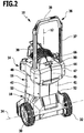
- the drawing shows schematically an inventive high-pressure cleaning device 10 is shown in a position of use, in which a longitudinal axis 12 of the high-pressure cleaning device 10 is vertically aligned.
- the high-pressure cleaning device 10 comprises a housing 14 having an upper housing part 16 and a lower housing part 18, which together surround a motor pump unit 20 with a motor 22 and a pump 24 driven by the motor 22.
- a cleaning liquid preferably water
- the cleaning liquid may be supplied to the pump 24 via a suction port 26, and the cleaning liquid pressurized by the pump 24 may be discharged from the pump 24 via a pressure port 28.
- a suction line preferably a suction hose can be connected, and to the pressure port 28, a pressure line, such as a pressure hose can be connected.
- two wheels 30, 32 are rotatably mounted on the lower housing part 18.
- the high-pressure cleaning device 10 can be moved along on a floor surface.
- the high-pressure cleaning device 10 starting from its in FIG. 1 shown use position in which the longitudinal axis 12 is vertically aligned to a common axis of rotation 34 of the two wheels 30, 32 are pivoted, so that the high-pressure cleaning device 10 can then be moved in the manner of a sack truck.
- the high-pressure cleaner 10 has a U-shaped push bar 36 which is disposed between a in FIG. 1 illustrated parking position and an in FIG. 2 shown operating position can be moved back and forth.
- the push bar 36 has a first leg 37 and a second leg 38, which are rigidly connected to each other via a handle 39.
- the handle 39 takes a greater distance to the housing 14 than in the parking position. This facilitates the user to grasp the handle 39 for moving the high-pressure cleaner 10 in a standing position.
- the upper housing part 16 comprises a first half-shell 41 and a second half-shell 42.
- the two half-shells 41, 42 surround an upper region of the motor pump unit 20 facing the handle 39 in the circumferential direction and are configured essentially mirror-symmetrically with respect to one another. They define therebetween a substantially vertically aligned parting plane 44 in which they meet with their edges facing each other and form a parting line 45 between them.
- the two half-shells 41, 42 each carry a cover part 47 or 48, which is screwed to the respective half-shell 41, 42.
- cover members 47, 48 each one of the Half shells 41 and 42 trained guide channel covered in which a leg 37 and 38 of the push bar 36 is slidably mounted.
- a guide channel 50 is in FIG. 3 shown schematically.
- the lower housing part 18 In alignment with the guide channels 50, the lower housing part 18 each have a quiver-like receptacle 52, 53. If the push bar 36 assumes its parking position, then an end area of the legs 37, 38 enters each receptacle 52, 53. If the push bar 36 is moved to its operating position, the free ends of the legs 37, 38 emerge from the receptacles 52, 53 and assume a position in the amount of the guide channels 50.
- a first positive locking element 55 and 56 is held, with the aid of the push bar 36 can be locked in its operating position.
- a second positive locking element 57 is held on each leg 37, 38, with the aid of the push bar 36 can be locked in its parking position.
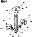
- the high-pressure cleaning device 10 has a locking device 60, which from one in the FIGS. 6 and 7 enlarged illustrated locking unit 62 and one in the Figures 3 and 4 shown return spring 63 is formed.
- the locking unit 62 is designed as a prefabricated unit in the form of a plastic molding. It has an actuator 65 with an actuating head 66 and an integrally adjoining actuating plunger 67, and a first and a second coupling member 69, 70, via which the actuating plunger 67 with a first or with a second locking member 72, 73 is pivotally connected.
- the two coupling members 69, 70 are identical.
- the first coupling member 69 has a first end 75 and a second end 76 and the second coupling member 70 has a first end 78 and a second end 79.
- the first coupling member 69 is followed by a first film hinge 81, via which the first coupling member 69 with the actuating plunger 67 is integrally and hingedly connected.
- a second film hinge 82 connects, via which the first coupling member 69 is integrally and hingedly connected to the first locking member 72.
- a third living hinge 84 adjoining the first end 78 of the second coupling member 70 is a third living hinge 84, via which the second coupling member 70 is integrally and hingedly connected to the actuating plunger 67, and the second end 79 of the second coupling member 70 is followed by a fourth Film hinge 85, via which the second coupling member 70 is integrally and hingedly connected to the second locking member 73.
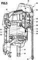
- the first half-shell 41 forms one in the FIGS. 4 and 5 recognizable guide channel 87 for the first locking member 72, and in an identical manner, the second half-shell 42 forms a not visible in the drawing guide channel for the second locking member 73 from.
- the two half-shells 41 and 42 each form a channel half 90a or 90b of a common guide channel 90, which receives the actuating head 66 and a guide section 92 of the actuating tappet 67 directly adjoining the actuating head 66. This is especially true of the FIGS. 4 and 5 clear.
- the actuating plunger 67 carries on its side facing away from the actuating head 66 lower end of a retaining pin 95 on which the return spring formed as a helical spring 63 is fixed.
- the return spring 63 occupies a position in a spring receptacle, which is formed by the two half-shells 41, 42 and which is aligned with the common guide channel 90.
- the return spring 63 exerts on the actuating plunger 67 a vertically upward spring force, which is transmitted via the coupling members 69, 70 to the locking members 72, 73. Due to the resilient restoring force, the locking members 72, 73 are pressed against the legs 37 and 38 of the push bar 36.
- the locking members 72, 73 each have a U-shaped locking receptacle 97, 98, which faces a leg 37 and 38, respectively. If the push bar 36 assumes its operating position, then the latching receptacles 97, 98 each interact positively with a corresponding latching projection of the first form-locking elements 55, 56. As a result, the push bar 36 can be locked in its operating position.
- the detent receptacles 97, 98 each interact with a corresponding latching projection of the second form-fit elements 57 in a form-fitting manner. As a result, the push bar 36 can be locked in its parking position.
- the user actuates the actuating member 65, wherein he pushes the actuating head 66 and with this the actuating plunger 67 along a first sliding axis 101 vertically downward against the action of the return spring 63.
- the guide portion 92 of the actuating plunger 67 is thereby displaced in the guide channel 90 along the first sliding axis 101.
- the movement of the actuating plunger 67 along the first sliding axis 101 vertically downward against the action of the return spring 63 has the result that the two locking members 72, 73 in the guide channels 87 along a second sliding axis 102, which is aligned perpendicular to the first sliding axis 101, on be moved towards each other, so that the locking members 72, 73 occupy a distance to the form-locking elements 55, 56 and 57 and release them. As a result, the locking of the push bar 36 is released. Subsequently, the user can move the push bar 36.
- the locking members 72, 73 By actuating the actuating member 65, thus, the locking members 72, 73, starting from their locking position, in which they with the interlocking elements 55, 56 and 57 form a positive connection, are moved against the action of the return spring 63 in a release position in which they release the positive-locking elements 55, 56 and 57 respectively.
- the locking members 72, 73 are acted upon by the return spring 63 with a spring force, under the action of which they automatically assume a position on the legs 37, 38 of the push bracket 36. If the push bar 36 is moved from its parking position to its operating position, then the locking members 72, 73 slide along the legs 37, 38 until they meet the first positive locking elements 55, 56 and under the action of the return spring 63 with the first positive locking elements 55, 56 automatically form a positive connection, so that the push handle 36 is locked in its operating position.
- the locking members 72, 73 slide along the legs 37, 38 until they meet the second positive locking elements 57 and under the action of the return spring 63 with the second positive locking elements 57 automatically form a positive connection, so that the push bar 36 is locked in its parking position.
- the locking of the push bar in the parking position and in the operating position is thus carried out automatically by means of the locking device 60 as soon as the push bar 36 has reached the respective position.
- the user has to operate the actuator 65.
- the locking unit consisting of the actuating member 65, the two coupling members 69, 70, the two locking members 72, 73 and the film hinges 81, 82, 84, 85 is configured in the form of a one-piece plastic molding and forms a prefabricated structural unit. This can be easily mounted on the housing 14 during assembly of the high-pressure cleaning device 10.
- the return spring 63 is placed on the spring holder 95 and in the guide channels 87 of the two half-shells 41, 42 a locking member 72, 73 is inserted in each case.
Description
- Die Erfindung betrifft ein Hochdruckreinigungsgerät mit den Merkmalen des Oberbegriffes von Patentanspruch 1.
- Mittels derartiger Hochdruckreinigungsgeräte kann eine Reinigungsflüssigkeit, vorzugsweise Wasser, unter Druck gesetzt und auf eine zu reinigende Fläche gerichtet werden. Die Reinigungsflüssigkeit kann der Pumpe des Hochdruckreinigungsgeräts über eine Flüssigkeitszufuhrleitung zugeführt werden. Die Reinigungsflüssigkeit wird von der Pumpe unter Druck gesetzt und die unter Druck gesetzte Reinigungsflüssigkeit kann über eine Flüssigkeitsabgabeleitung, beispielsweise einen Hochdruckschlauch, abgegeben werden. Zum Verfahren des Hochdruckreinigungsgeräts auf einer Bodenfläche weist das Hochdruckreinigungsgerät mindestens zwei drehbar gelagerte Laufräder auf. Um dem Benutzer das Verfahren des Hochdruckreinigungsgerätes zu erleichtern, umfasst das Hochdruckreinigungsgerät einen Schubbügel, der zwischen einer Parkstellung und einer Betriebsstellung hin und her bewegt und vom Benutzer ergriffen werden kann. In der Parkstellung und/oder in der Betriebsstellung kann der Schubbügel arretiert werden. Hierzu kommt eine Arretierungseinrichtung zum Einsatz mit einem Arretierungsglied, das mit dem Schubbügel zusammenwirkt, um den Schubbügel zu arretieren. Durch Betätigen eines Betätigungsglieds kann das Arretierungsglied aus einer Arretierungsstellung, in der das Arretierungsglied den Schubbügel arretiert, in eine Freigabestellung bewegt werden, in der das Arretierungsglied den Schubbügel freigibt. Zur Kopplung des Betätigungsglieds mit dem mindestens einen Arretierungsglied kommt mindestens ein Kopplungsglied zum Einsatz.
- Zum Montieren des Hochdruckreinigungsgeräts müssen dessen Bestandteile zusammengefügt werden, wobei keine Montagefehler auftreten dürfen.
- Aus der
DE 298 12 015 U1 ist ein Teleskopgriff für Gepäck bekannt, der zwei äußere rohrförmige Elemente und zwei innere rohrförmige Elemente aufweist. - Die inneren rohrförmigen Elemente sind gleitend in die äußeren rohrförmigen Elemente eingesetzt.
- In der
US 5,429,306 A wird ein Hochdruckreinigungsgerät beschrieben mit einem Gehäuse, an dessen Unterseite im Bereich einer Seitenkante Rollen angeordnet sind und in dem ein in das Gehäuse einschiebbarer Griff gelagert ist, der zwischen einer in das Gehäuse eingeschobenen Stellung und einer ausgezogenen Stellung verschoben und in diesen beiden Stellungen fixiert werden kann. - Ein Hochdruckreinigungsgerät mit den Merkmalen des Oberbegriffs von Patentanspruch 1 ist aus der
DE 20 2005 019 979 U1 bekannt. - Aufgabe der vorliegenden Erfindung ist es, ein Hochdruckreinigungsgerät der eingangs genannten Art derart weiterzubilden, dass es kostengünstiger und einfacher montierbar ist.
- Diese Aufgabe wird durch ein Hochdruckreinigungsgerät mit den Merkmalen von Patentanspruch 1 gelöst.
- Die Bereitstellung einer vorgefertigten Baueinheit, die das Betätigungsglied, das mindestens eine Kopplungsglied und das mindestens eine Arretierungsglied ausbildet, erleichtert die Montage des Hochdruckreinigungsgeräts, da die vorgefertigte Baueinheit am oder im Gehäuse gelagert werden kann, ohne dass die einzelnen Bestandteile der Baueinheit in mehreren Montageschritten am Gehäuse zusammengefügt werden müssen. Vielmehr kann die komplette Baueinheit in einem einzigen Montageschritt am oder im Gehäuse positioniert werden. Die Montage des Hochdruckreinigungsgeräts kann somit in kürzerer Zeit und damit kostengünstiger erzielt werden. Darüber hinaus werden durch die Bereitstellung der vorgefertigten Baueinheit Montagefehler vermieden.
- Das Betätigungsglied weist einen Betätigungsstößel auf und das mindestens eine Kopplungsglied umfasst ein erstes und ein zweites Ende, wobei es mit dem ersten Ende am Betätigungsstößel und mit dem zweiten Ende an einem Arretierungsglied angelenkt ist. Das mindestens eine Kopplungsglied ist somit einerseits mit dem Betätigungsstößel des Betätigungsglieds und andererseits mit einem Arretierungsglied gelenkig verbunden. Dies erlaubt es, eine Bewegung des Betätigungsglieds ausgehend vom Betätigungsstößel über das mindestens eine Kopplungsglied auf ein Arretierungsglied zu übertragen, wobei durch die gelenkige Verbindung des mindestens einen Kopplungsglieds einerseits mit dem Betätigungsstößel und andererseits mit einem Antriebselement auf einfache Weise eine Änderung der Bewegungsrichtung erzielt werden kann, so dass die Bewegungsrichtung des Betätigungsglieds nicht mit der Bewegungsrichtung des mindestens einen Arretierungsglieds übereinstimmen muss. Beispielsweise kann vorgesehen sein, dass das Betätigungsglied vom Benutzer in einer ersten Bewegungsrichtung bewegt werden kann und sich dadurch mindestens ein Arretierungsglied in einer zweiten Bewegungsrichtung bewegt, die im Winkel, vorzugsweise senkrecht zur ersten Bewegungsrichtung ausgerichtet ist.
- Das mindestens eine Kopplungsglied ist über ein stößelseitiges Filmscharnier mit dem Betätigungsstößel einstückig verbunden. Der Betätigungsstößel und das mindestens eine Kopplungsglied bilden ein einteiliges Bauteil aus, das vorzugsweise aus einem Kunststoffmaterial gefertigt ist. Das stößelseitige Filmscharnier erlaubt es, das mindestens eine Kopplungsglied relativ zum Betätigungsstößel zu bewegen, beispielsweise zu verschwenken oder zu verschieben.
- Außerdem ist das mindestens eine Kopplungsglied über ein arretierungseitiges Filmscharnier mit einem Arretierungsglied einstückig verbunden. Das mindestens eine Kopplungsglied und das mit diesem verbundene Arretierungsglied bilden ein einteiliges Bauteil aus, das vorzugsweise aus einem Kunststoffmaterial gefertigt ist. Das arretierungsseitige Filmscharniers erlaubt es, das Arretierungsglied relativ zum Kopplungsglied zu bewegen, beispielsweise zu verschwenken oder zu verschieben.
- Bevorzugt ist der Schubbügel in seiner Betriebsstellung arretierbar. Dies gibt dem Benutzer die Möglichkeit, den Schubbügel zum Verfahren des Hochdruckreinigungsgerätes in seine Betriebsstellung zu bewegen und in dieser Stellung zu arretieren, so dass er anschließend den Schubbügel ergreifen kann, um das Hochdruckreinigungsgerät zu schieben oder zu drücken.
- Alternativ oder ergänzend kann vorgesehen sein, dass der Schubbügel in seiner Parkstellung arretierbar ist. Dies gibt dem Benutzer die Möglichkeit, das Hochdruckreinigungsgerät am Schubbügel zu tragen, wobei der Schubbügel in der Parkstellung arretiert ist.
- Der Schubbügel weist bevorzugt einen Handgriff auf, der in der Parkstellung des Schubbügels einen geringeren Abstand zum Gehäuse des Hochdruckreinigungsgerätes einnimmt als in der Betriebsstellung.
- Von Vorteil ist es, wenn der Schubbügel am Gehäuse verschiebbar und/oder verschwenkbar gelagert ist.
- Insbesondere kann vorgesehen sein, dass der Schubbügel um eine parallel zu einer Längsachse des Hochdruckreinigungsgerätes ausgerichtete Schiebeachse zwischen seiner Parkstellung und seiner Betriebsstellung hin und her bewegbar am Gehäuse gelagert und sowohl in der Parkstellung als auch in der Betriebsstellung arretierbar ist.
- Von besonderem Vorteil ist es, wenn die vorgefertigte Baueinheit, die das Betätigungsglied, das mindestens eine Kopplungsglied und das mindestens eine Arretierungsglied ausbildet, als einteiliges Kunststoffformteil ausgestaltet ist. Die Anzahl der Bauteile des Hochdruckreinigungsgeräts kann dadurch verringert werden und dies wiederum ermöglicht eine besonders kostengünstige und einfache Montage des Hochdruckreinigungsgeräts.
- Bei einer vorteilhaften Ausführungsform sind das Betätigungsglied und das mindestens eine Arretierungsglied am Gehäuse verschiebbar gelagert. Das Gehäuse weist hierzu Lagerelemente auf, die mit dem Betätigungsglied bzw. mit dem mindestens einen Arretierungsglied derart zusammenwirken, dass das Betätigungsglied und das mindestens eine Arretierungsglied relativ zum Gehäuse verschoben werden können.
- Günstig ist es, wenn das Betätigungsglied entlang einer ersten Schiebeachse verschiebbar ist und das mindestens eine Arretierungsglied entlang einer zweiten Schiebeachse verschiebbar ist, wobei die zweite Schiebeachse im Winkel zur ersten Schiebeachse ausgerichtet ist.
- Die erste Schiebeachse kann beispielsweise parallel zu einer Längsachse des Hochdruckreinigungsgeräts ausgerichtet sein.
- Insbesondere kann vorgesehen sein, dass das Hochdruckreinigungsgerät auf einer Standfläche, beispielsweise einer Bodenfläche, mit vertikal ausgerichteter Längsachse positioniert werden kann, wobei auch die erste Schiebeachse vertikal ausgerichtet ist.
- Die zweite Schiebeachse ist günstigerweise senkrecht zur ersten Schiebeachse ausgerichtet.
- Es kann vorgesehen sein, dass die zweite Schiebeachse quer zu einer Längsachse des Hochdruckreinigungsgeräts ausgerichtet ist.
- Zum Bewegen des mindestens einen Arretierungsglieds kann der Benutzer das Betätigungsglied betätigen. Insbesondere kann vorgesehen sein, dass der Benutzer das Betätigungsglied nach Art eines Druckknopfes verschiebt.
- Von besonderem Vorteil ist es, wenn das mindestens eine Arretierungsglied entgegen der Wirkung einer federelastischen Rückstellkraft aus der Arretierungsstellung in die Freigabestellung bewegbar ist. Die Bewegung des Betätigungsglieds wird über das mindestens eine Kopplungsglied auf das mindestens eine Arretierungsglied übertragen. Durch Betätigen des Betätigungsglieds geht das Arretierungsglied von seiner Arretierungsstellung, in der es den Schubbügel fixiert, in eine Freigabestellung über, in der es den Schubbügel freigibt. Der Übergang von der Arretierungsstellung in die Freigabestellung erfolgt günstigerweise entgegen der Wirkung einer federelastischen Rückstellkraft. Eine derartige Ausgestaltung hat den Vorteil, dass das mindestens eine Arretierungsglied selbsttätig seine Arretierungsstellung einnehmen kann, wenn der Benutzer den Schubbügel in die Parkstellung oder in die Betriebsstellung bewegt. Der Schubbügel kann somit in der gewünschten Stellung selbsttätig arretiert werden. Die Bereitstellung der federelastischen Rückstellkraft erleichtert folglich die Handhabung des Hochdruckreinigungsgeräts.
- Bei einer vorteilhaften Ausführungsform des erfindungsgemäßen Hochdruckreinigungsgeräts ist das mindestens eine Arretierungsglied in der Arretierungsstellung mit dem Schubbügel formschlüssig verbunden. Beispielsweise kann der Schubbügel mindestens ein Formschlusselement aufweisen, das in der Parkstellung oder in der Betriebsstellung des Schubbügels mit einem Arretierungsglied zusammenwirkt zur Herstellung einer formschlüssigen Verbindung. Das Formschlusselement kann zum Beispiel einen Vorsprung aufweisen, der zur Arretierung des Schubbügels in eine Ausnehmung eines Arretierungsglieds formschlüssig eingreift. Alternativ oder ergänzend kann vorgesehen sein, dass das mindestens eine Arretierungsglied einen Vorsprung umfasst, der zur Arretierung des Schubbügels in eine Ausnehmung des Formschlusselements eintaucht.
- Günstig ist es, wenn der Schubbügel zumindest ein Paar von im Abstand zueinander angeordneten Formschlusselementen aufweist, denn dies erlaubt es, den Schubbügel in der Parkstellung und in der Betriebsstellung zu arretieren, wobei in jeder Stellung ein Formschlusselement mit einem Arretierungsglied zusammenwirkt.
- Besonders vorteilhaft ist es, wenn das mindestens eine Arretierungsglied in der Arretierungsstellung mit dem Schubbügel verrastet. Das mindestens eine Arretierungsglied kann ein Rastelement ausbilden, das mit einem korrespondierenden Rastelement des Schubbügels zusammenwirkt, um den Schubbügel in einer gewünschten Stellung zu arretieren.
- Bei einer vorteilhaften Ausführungsform weist das Gehäuse des Hochdruckreinigungsgeräts einen ersten Führungskanal auf, in dem ein Führungsabschnitt des Betätigungsglieds verschiebbar gehalten ist. Wie bereits erwähnt, kann beispielsweise vorgesehen sein, dass das Betätigungsglied einen Betätigungsstößel aufweist. Günstig ist es, wenn zumindest ein Abschnitt des Betätigungsstößels im ersten Führungskanal des Gehäuses verschiebbar gehalten ist.
- Alternativ oder ergänzend kann vorgesehen sein, dass das Gehäuse für jedes Arretierungsglied einen zweiten Führungskanal aufweist, in dem das jeweilige Arretierungsglied verschiebbar gelagert ist. Hierbei ist es vorteilhaft, wenn jedes Arretierungsglied von einem zweiten Führungskanal vollständig aufgenommen wird, so dass der zweite Führungskanal das Arretierungsglied in Umfangsrichtung vollständig umgibt.
- Der Schubbügel ist günstigerweise U-förmig ausgestaltet und weist zwei Schenkel auf, die über einen Handgriff miteinander verbunden sind, und das Gehäuse weist bevorzugt zwei dritte Führungskanäle auf, in denen jeweils ein Schenkel verschiebbar gelagert ist. Die dritten Führungskanäle sind bei einer vorteilhaften Ausführungsform der Erfindung parallel zu einer Längsachse des Hochdruckreinigungsgeräts ausgerichtet.
- Die Schenkel des U-förmigen Schubbügels tragen bei einer vorteilhaften Ausführungsform der Erfindung zumindest an ihrem dem Handgriff abgewandten Ende jeweils ein erstes Formschlusselement, das in der Betriebsstellung des Schubbügels mit einem Arretierungsglied formschlüssig zusammenwirkt.
- Günstigerweise tragen die Schenkel jeweils ein erstes Formschlusselement und ein im Abstand zum ersten Formschlusselement positioniertes zweites Formschlusselement, wobei das erste Formschlusselement in der Betriebsstellung des Schubbügels und das zweite Formschlusselement in der Parkstellung des Schubbügels mit einem Arretierungsglied formschlüssig zusammenwirkt.
- Von Vorteil ist es, wenn die vorgefertigte Baueinheit der Arretierungseinrichtung zwei Arretierungsglieder ausbildet, die jeweils über ein Kopplungsglied mit dem Betätigungsglied gelenkig verbunden sind und zur Arretierung des Schubbügels jeweils mit einem Schenkel des Schubbügels zusammenwirken. Die Bereitstellung von zwei Arretierungsgliedern erhöht die mechanische Stabilität der Arretierung des Schubbügels. Dies verringert beispielsweise die Gefahr, dass sich der Schubbügel beim Verfahren des Hochdruckreinigungsgeräts unbeabsichtigt von seiner Betriebsstellung in seine Parkstellung bewegt.
- Die beiden Arretierungsglieder sind vorteilhafterweise jeweils in einem Führungskanal des Gehäuses verschiebbar gelagert. Das Gehäuse bildet bei einer derartigen Ausführungsform der Erfindung für jedes der beiden Arretierungsglieder einen separaten Führungskanal aus, der das jeweilige Arretierungsglied aufnimmt.
- Günstig ist es, wenn die beiden Arretierungsglieder entlang einer gemeinsamen Schiebeachse verschiebbar sind.
- Von Vorteil ist es, wenn die gemeinsame Schiebeachse der beiden Arretierungsglieder senkrecht zu einer Längsachse des Hochdruckreinigungsgeräts ausgerichtet ist.
- Bei einer vorteilhaften Ausführungsform der Erfindung führen die beiden Arretierungsglieder beim Übergang aus ihrer Arretierungsstellung in ihre Freigabestellung eine gegenläufige Bewegung aus.
- Bei einer besonders bevorzugten Ausgestaltung des erfindungsgemäßen Hochdruckreinigungsgeräts sind die beiden Arretierungsglieder spiegelsymmetrisch zu einer Längsachse des Betätigungsglieds angeordnet.
- Von Vorteil ist es, wenn die beiden Kopplungsglieder, über die die Arretierungsglieder jeweils mit dem Betätigungsglied verbunden sind, spiegelsymmetrisch zur Längsachse des Betätigungsglieds angeordnet sind.
- Die spiegelsymmetrische Anordnung der Arretierungsglieder und/oder der Kopplungsglieder erleichtert die Montage der vorgefertigten Baueinheit der Arretierungseinrichtung. Die Gefahr von Montagefehlern wird dadurch besonders gering gehalten.
- Das Gehäuse weist bei einer vorteilhaften Ausführungsform der Erfindung zwei Halbschalen auf, in denen jeweils ein Arretierungsglied verschiebbar gehalten ist. Der Einsatz von zwei Halbschalen hat eine weitere Vereinfachung der Montage des Hochdruckreinigungsgeräts zur Folge. Bei der Montage des Hochdruckreinigungsgeräts kann in jede Halbschale ein Arretierungsglied eingesetzt werden und anschließend können die beiden Halbschalen zusammengefügt werden.
- Von besonderem Vorteil ist es, wenn die beiden Halbschalen gemeinsam einen Führungskanal ausbilden, in dem das Betätigungsglied verschiebbar gehalten ist. Der Führungskanal kann einen Führungsabschnitt des Betätigungsglieds in Umfangsrichtung umgeben. Der Führungskanal wird gemeinsam von den beiden Halbschalen ausgebildet. Dies ermöglicht es, das Betätigungsglied mit seinem Führungsabschnitt in den Führungskanal einzusetzen, wenn die beiden Halbschalen zusammengefügt werden.
- Günstig ist es, wenn die beiden Halbschalen eine in einer Gebrauchslage des Hochdruckreinigungsgeräts vertikal ausgerichtete Trennebene definieren. Unter einer Gebrauchslage des Hochdruckreinigungsgeräts wird hierbei eine Lage des Hochdruckreinigungsgeräts verstanden, die es während des Betriebs des Hochdruckreinigungsgeräts einnehmen kann. Eine Längsachse des Hochdruckreinigungsgeräts kann in dieser Gebrauchslage beispielsweise vertikal ausgerichtet sein. Die Bereitstellung einer vertikalen Trennebene ermöglicht eine besonders einfache Montage des Hochdruckreinigungsgeräts, da die beiden Halbschalen seitlich an die Motorpumpeneinheit angesetzt werden können, um diese nach erfolgter Montage in Umfangsrichtung vollständig zu umgeben. Die Motorpumpeneinheit wird aus dem Motor und der Pumpe gebildet, die in einem vorherigen Montageschritt zusammengefügt werden können.
- Günstig ist es, wenn vor dem Zusammenfügen der beiden Halbschalen jeweils ein Arretierungsglied in einen von einer Halbschale gebildeten Führungskanal eingesetzt werden kann und wenn anschließend das Betätigungsglied in einen von beiden Halbschalen gemeinsam gebildeten Führungskanal eingesetzt werden kann. Dies ermöglicht eine besonders einfache Montage des Hochdruckreinigungsgeräts.
- Die nachfolgende Beschreibung einer vorteilhaften Ausführungsform der Erfindung dient im Zusammenhang mit der Zeichnung der näheren Erläuterung. Es zeigen:
- Figur 1:
- eine erste perspektivische Darstellung eines erfindungsgemäßen Hochdruckreinigungsgeräts, wobei ein Schubbügel des Hochdruckreinigungsgeräts eine Parkstellung einnimmt;
- Figur 2:
- eine zweite perspektivische Darstellung des Hochdruckreinigungsgeräts aus
Figur 1 , wobei der Schubbügel eine Betriebsstellung einnimmt; - Figur 3:
- eine perspektivische Darstellung des Hochdruckreinigungsgeräts nach Art einer Explosionszeichnung;
- Figur 4:
- eine perspektivische Darstellung einer Halbschale eines Gehäuses des Hochdruckreinigungsgeräts aus
Figur 1 in Kombination mit dem Schubbügel und einer Arretierungseinrichtung, wobei der Schubbügel seine Betriebsstellung einnimmt; - Figur 5:
- eine perspektivische Darstellung einer Halbschale des Gehäuses des Hochdruckreinigungsgerätes entsprechend
Figur 4 , wobei der Schubbügel seine Parkstellung einnimmt; - Figur 6:
- eine perspektivische Darstellung einer vorgefertigten Baueinheit der Arretierungseinrichtung, und
- Figur 7:
- eine Vorderansicht der vorgefertigten Baueinheit aus
Figur 6 . - In der Zeichnung ist schematisch ein erfindungsgemäßes Hochdruckreinigungsgerät 10 in einer Gebrauchslage dargestellt, in der eine Längsachse 12 des Hochdruckreinigungsgeräts 10 vertikal ausgerichtet ist. Das Hochdruckreinigungsgerät 10 umfasst ein Gehäuse 14 mit einem oberen Gehäuseteil 16 und einem unteren Gehäuseteil 18, die gemeinsam eine Motorpumpeneinheit 20 mit einem Motor 22 und einer vom Motor 22 angetriebenen Pumpe 24 umgeben. Mittels der Pumpe 24 kann eine Reinigungsflüssigkeit, vorzugsweise Wasser, unter Druck gesetzt werden. Die Reinigungsflüssigkeit kann der Pumpe 24 über einen Sauganschluss 26 zugeführt werden, und die von der Pumpe 24 unter Druck gesetzte Reinigungsflüssigkeit kann von der Pumpe 24 über einen Druckanschluss 28 abgegeben werden. An den Sauganschluss 26 kann eine Saugleitung, vorzugsweise ein Saugschlauch angeschlossen werden, und an den Druckanschluss 28 kann eine Druckleitung, beispielsweise ein Druckschlauch angeschlossen werden.
- Am unteren Gehäuseteil 18 sind zwei Laufräder 30, 32 drehbar gelagert. Mittels der Laufräder 30, 32 kann das Hochdruckreinigungsgerät 10 entlang an einer Bodenfläche verfahren werden. Hierzu kann das Hochdruckreinigungsgerät 10 ausgehend von seiner in
Figur 1 dargestellten Gebrauchslage, in der die Längsachse 12 vertikal ausgerichtet ist, um eine gemeinsame Drehachse 34 der beiden Laufräder 30, 32 verschwenkt werden, so dass das Hochdruckreinigungsgerät 10 anschließend nach Art einer Sackkarre verfahren werden kann. - Um dem Benutzer das Verfahren des Hochdruckreinigungsgeräts 10 zu erleichtern, weist das Hochdruckreinigungsgerät 10 einen U-förmigen Schubbügel 36 auf, der zwischen einer in
Figur 1 dargestellten Parkstellung und einer inFigur 2 dargestellten Betriebsstellung hin und her bewegt werden kann. Der Schubbügel 36 weist einen ersten Schenkel 37 und einen zweiten Schenkel 38 auf, die über einen Handgriff 39 starr miteinander verbunden sind. In der Betriebsstellung nimmt der Handgriff 39 einen größeren Abstand zum Gehäuse 14 ein als in der Parkstellung. Dies erleichtert es dem Benutzer, den Handgriff 39 zum Verfahren des Hochdruckreinigungsgeräts 10 in stehender Position zu ergreifen. - Das obere Gehäuseteil 16 umfasst eine erste Halbschale 41 und eine zweite Halbschale 42. Die beiden Halbschalen 41, 42 umgeben einen dem Handgriff 39 zugewandten oberen Bereich der Motorpumpeneinheit 20 in Umfangsrichtung und sind im Wesentlichen spiegelsymmetrisch zueinander ausgestaltet. Sie definieren zwischen sich eine im Wesentlichen vertikal ausgerichtete Trennebene 44, in der sie mit ihren einander zugewandten Rändern aufeinandertreffen und zwischen sich eine Trennfuge 45 ausbilden.
- An ihren einander abgewandten Außenseiten tragen die beiden Halbschalen 41, 42 jeweils ein Abdeckteil 47 bzw. 48, das mit der jeweiligen Halbschale 41, 42 verschraubt ist. Von den Abdeckteilen 47, 48 wird jeweils ein von den Halbschalen 41 bzw. 42 ausgebildeter Führungskanal abgedeckt, in dem ein Schenkel 37 bzw. 38 des Schubbügels 36 verschiebbar gelagert ist. Ein Führungskanal 50 ist in
Figur 3 schematisch dargestellt. - Fluchtend zu den Führungskanälen 50 weist das untere Gehäuseteil 18 jeweils eine köcherartige Aufnahme 52, 53 auf. Nimmt der Schubbügel 36 seine Parkstellung ein, so taucht in jede Aufnahme 52, 53 ein Endbereich der Schenkel 37, 38 ein. Wird der Schubbügel 36 in seine Betriebsstellung bewegt, so tauchen die freien Enden der Schenkel 37, 38 aus den Aufnahmen 52, 53 auf und nehmen eine Position in Höhe der Führungskanäle 50 ein.
- An den freien Enden der Schenkel 37, 38 ist jeweils ein erstes Formschlusselement 55 bzw. 56 gehalten, mit dessen Hilfe der Schubbügel 36 in seiner Betriebsstellung arretiert werden kann. Im Abstand zum ersten Formschlusselement 55 bzw. 56 ist an jedem Schenkel 37, 38 ein zweites Formschlusselement 57 gehalten, mit dessen Hilfe der Schubbügel 36 in seiner Parkstellung arretiert werden kann.
- Zur Arretierung des Schubbügels 36 weist das Hochdruckreinigungsgerät 10 eine Arretierungseinrichtung 60 auf, die von einer in den
Figuren 6 und7 vergrößert dargestellten Arretierungseinheit 62 und einer in denFiguren 3 und4 dargestellten Rückstellfeder 63 gebildet wird. - Die Arretierungseinheit 62 ist als vorgefertigte Baueinheit in Form eines Kunststoffformteils ausgestaltet. Sie weist ein Betätigungsglied 65 auf mit einem Betätigungskopf 66 und einem sich daran einstückig anschließenden Betätigungsstößel 67, sowie ein erstes und ein zweites Kopplungsglied 69, 70, über die der Betätigungsstößel 67 mit einem ersten beziehungsweise mit einem zweiten Arretierungsglied 72, 73 gelenkig verbunden ist. Die beiden Kopplungsglieder 69, 70 sind identisch ausgebildet. Das erste Kopplungsglied 69 hat ein erstes Ende 75 und ein zweites Ende 76 und das zweite Kopplungsglied 70 hat ein erstes Ende 78 und ein zweites Ende 79. An das erste Ende 75 des ersten Kopplungsglieds 69 schließt sich ein erstes Filmscharnier 81 an, über das das erste Kopplungsglied 69 mit dem Betätigungsstößel 67 einstückig und gelenkig verbunden ist. An das zweite Ende 76 des ersten Kopplungsglieds 69 schließt sich ein zweites Filmscharnier 82 an, über das das erste Kopplungsglied 69 einstückig und gelenkig mit dem ersten Arretierungsglied 72 verbunden ist.
- In entsprechender Weise schließt sich an das erste Ende 78 des zweiten Kopplungsglieds 70 ein drittes Filmscharnier 84 an, über das das zweite Kopplungsglied 70 einstückig und gelenkig mit dem Betätigungsstößel 67 verbunden ist, und an das zweite Ende 79 des zweiten Kopplungsglieds 70 schließt sich ein viertes Filmscharnier 85 an, über das das zweite Kopplungsglied 70 einstückig und gelenkig mit dem zweiten Arretierungsglied 73 verbunden ist.
- Die erste Halbschale 41 bildet einen in den
Figuren 4 und5 erkennbaren Führungskanal 87 für das erste Arretierungsglied 72 aus, und in identischer Weise bildet die zweite Halbschale 42 einen in der Zeichnung nicht erkennbaren Führungskanal für das zweite Arretierungsglied 73 aus. - Die beiden Halbschalen 41 und 42 bilden jeweils eine Kanalhälfte 90a beziehungsweise 90b eines gemeinsamen Führungskanals 90 aus, der den Betätigungskopf 66 sowie einen sich an den Betätigungskopf 66 unmittelbar anschließenden Führungsabschnitt 92 des Betätigungsstößels 67 aufnimmt. Dies wird insbesondere aus den
Figuren 4 und5 deutlich. - Der Betätigungsstößel 67 trägt an seinem dem Betätigungskopf 66 abgewandten unteren Ende einen Haltezapfen 95, an dem die als Schraubenfeder ausgebildete Rückstellfeder 63 festgelegt ist. Die Rückstellfeder 63 nimmt eine Position in einer Federaufnahme ein, die von den beiden Halbschalen 41, 42 gebildet wird und die fluchtend zum gemeinsamen Führungskanal 90 ausgerichtet ist.
- Die Rückstellfeder 63 übt auf den Betätigungsstößel 67 eine vertikal nach oben gerichtete Federkraft aus, die über die Kopplungsglieder 69, 70 auf die Arretierungsglieder 72, 73 übertragen wird. Aufgrund der federelastischen Rückstellkraft werden die Arretierungsglieder 72, 73 gegen die Schenkel 37 bzw. 38 des Schubbügels 36 gedrückt. Die Arretierungsglieder 72, 73 weisen jeweils eine U-förmige Rastaufnahme 97, 98 auf, die einem Schenkel 37 bzw. 38 zugewandt ist. Nimmt der Schubbügel 36 seine Betriebsstellung ein, dann wirken die Rastaufnahmen 97, 98 jeweils mit einem korrespondierenden Rastvorsprung der ersten Formschlusselemente 55, 56 formschlüssig zusammen. Dadurch kann der Schubbügel 36 in seiner Betriebsstellung arretiert werden. Nimmt der Schubbügel 36 seine Parkstellung ein, dann wirken die Rastaufnahmen 97, 98 jeweils mit einem korrespondierenden Rastvorsprung der zweiten Formschlusselemente 57 formschlüssig zusammen. Dadurch kann der Schubbügel 36 in seiner Parkstellung arretiert werden.
- Soll die Arretierung des Schubbügels 36 gelöst werden, so betätigt der Benutzer das Betätigungsglied 65, wobei er den Betätigungskopf 66 und mit diesem auch den Betätigungsstößel 67 entlang einer ersten Schiebeachse 101 vertikal nach unten drückt entgegen der Wirkung der Rückstellfeder 63. Der Führungsabschnitt 92 des Betätigungsstößels 67 wird hierbei im Führungskanal 90 entlang der ersten Schiebeachse 101 verschoben. Die Bewegung des Betätigungsstößels 67 entlang der ersten Schiebeachse 101 vertikal nach unten entgegen der Wirkung der Rückstellfeder 63 hat zur Folge, dass die beiden Arretierungsglieder 72, 73 in den Führungskanälen 87 entlang einer zweiten Schiebeachse 102, die senkrecht zur ersten Schiebeachse 101 ausgerichtet ist, auf einander zu verschoben werden, so dass die Arretierungsglieder 72, 73 einen Abstand zu den Formschlusselementen 55, 56 bzw. 57 einnehmen und diese freigeben. Dadurch wird die Arretierung des Schubbügels 36 gelöst. Anschließend kann der Benutzer den Schubbügel 36 verschieben.
- Durch Betätigen des Betätigungsglieds 65 können somit die Arretierungsglieder 72, 73 ausgehend von ihrer Arretierungsstellung, in der sie mit den Formschlusselementen 55, 56 bzw. 57 einen Formschluss ausbilden, entgegen der Wirkung der Rückstellfeder 63 in eine Freigabestellung verschoben werden, in der sie die Formschlusselemente 55, 56 bzw. 57 freigeben.
- Die Arretierungsglieder 72, 73 werden von der Rückstellfeder 63 mit einer Federkraft beaufschlagt, unter deren Wirkung sie selbsttätig eine Position an den Schenkeln 37, 38 des Schubbügels 36 einnehmen. Wird der Schubbügel 36 von seiner Parkstellung in seine Betriebsstellung bewegt, so gleiten die Arretierungsglieder 72, 73 so lange an den Schenkeln 37, 38 entlang, bis sie auf die ersten Formschlusselemente 55, 56 treffen und unter der Wirkung der Rückstellfeder 63 mit den ersten Formschlusselementen 55, 56 selbsttätig einen Formschluss ausbilden, so dass der Schubbügel 36 in seiner Betriebsstellung arretiert ist. Wird der Schubbügel 36 von seiner Betriebsstellung in seine Parkstellung bewegt, so gleiten die Arretierungsglieder 72, 73 so lange an den Schenkeln 37, 38 entlang, bis sie auf die zweiten Formschlusselemente 57 treffen und unter der Wirkung der Rückstellfeder 63 mit den zweiten Formschlusselementen 57 selbsttätig einen Formschluss ausbilden, so dass der Schubbügel 36 in seiner Parkstellung arretiert ist. Die Arretierung des Schubbügels in der Parkstellung und in der Betriebsstellung erfolgt somit mittels der Arretierungseinrichtung 60 selbsttätig, sobald der Schubbügel 36 die jeweilige Stellung erreicht hat. Zum Lösen der Arretierung hat der Benutzer das Betätigungsglied 65 zu betätigen.
- Wie bereits erwähnt, ist die aus dem Betätigungsglied 65, den beiden Kopplungsgliedern 69, 70, den beiden Arretierungsgliedern 72, 73 sowie den Filmscharnieren 81, 82, 84, 85 bestehende Arretierungseinheit in Form eines einteiligen Kunststoffformteils ausgestaltet und bildet eine vorgefertigte Baueinheit aus. Diese kann bei der Montage des Hochdruckreinigungsgeräts 10 auf einfache Weise am Gehäuse 14 montiert werden. Hierzu wird die Rückstellfeder 63 auf die Federhalterung 95 aufgesetzt und in die Führungskanäle 87 der beiden Halbschalen 41, 42 wird jeweils ein Arretierungsglied 72, 73 eingeführt. Beim Zusammenfügen der beiden Halbschalen 41, 42 nimmt der Führungsabschnitt 92 des Betätigungsstößels 67 eine Position im gemeinsamen Führungskanal 90 der beiden Halbschalen 41, 42 ein und die Rückstellfeder 63 nimmt eine Position in der von den beiden Halbschalen 41, 42 gebildeten Federaufnahme ein. Die beiden Halbschalen 41, 42 können anschließend miteinander verschraubt werden. In einem nachfolgenden Montageschritt kann der Schubbügel 36 mit seinen beiden Schenkeln 37, 38, an denen jeweils bereits ein zweites Formschlusselement 57 festgelegt ist, in die Führungskanäle 50 eingesetzt werden, so dass die freien Enden der Schenkel 37, 38 nach unten aus den Führungskanälen 50 herausragen. Es können dann die ersten Formschlusselemente 55, 56 an den freien Enden der Schenkel 37, 38 fixiert werden. In einem nachfolgenden Montageschritt können an die einander abgewandten Außenseiten der Halbschalen 41, 42 die Abdeckteile 47 bzw. 48 angeschraubt werden. Die Montage des Hochdruckreinigungsgeräts 10 gestaltet sich somit verhältnismäßig einfach und die Gefahr von Montagefehlern ist gering.
Claims (18)
- Hochdruckreinigungsgerät mit einem Gehäuse (14), in dem ein Motor (22) und eine vom Motor (22) angetriebene Pumpe (24) für eine Reinigungsflüssigkeit angeordnet sind, und mit mindestens zwei drehbar gelagerten Laufrädern (30, 32) zum Verfahren des Hochdruckreinigungsgeräts, einem zwischen einer Parkstellung und einer Betriebsstellung hin und her bewegbaren Schubbügel (36) und einer Arretierungseinrichtung (60) zum lösbaren Arretieren des Schubbügels (36) in der Parkstellung und/oder in der Betriebsstellung, wobei die Arretierungseinrichtung (60) ein Betätigungsglied (65) aufweist, das über mindestens ein Kopplungsglied (69, 70) mit mindestens einem mit dem Schubbügel (36) zusammenwirkenden Arretierungsglied (72, 73) gekoppelt ist, das durch Betätigen des Betätigungsglieds (65) aus einer Arretierungsstellung in eine Freigabestellung bewegbar ist, wobei die Arretierungseinrichtung (60) eine vorgefertigte Baueinheit (62) umfasst, die das Betätigungsglied (65), das mindestens eine Kopplungsglied (69, 70) und das mindestens eine Arretierungsglied (72, 73) ausbildet und am oder im Gehäuse (14) bewegbar gelagert ist und wobei das Betätigungsglied (65) einen Betätigungsstößel (67) aufweist und dass das mindestens eine Kopplungsglied (69, 70) ein erstes und ein zweites Ende (75, 76; 78, 79) umfasst, wobei es mit dem ersten Ende (75; 78) am Betätigungsstößel (67) und mit dem zweiten Ende (76; 79) an einem Arretierungsglied (72, 73) angelenkt ist, dadurch gekennzeichnet, dass das mindestens eine Kopplungsglied (69, 70) über ein stößelseitiges Filmscharnier (81, 84) mit dem Betätigungsstößel (67) einstückig verbunden ist und dass das mindestens eine Kopplungsglied (69, 70) über ein arretierungsseitiges Filmscharnier (82, 85) mit einem Arretierungsglied (72, 73) einstückig verbunden ist.
- Hochdruckreinigungsgerät nach Anspruch 1, dadurch gekennzeichnet, dass die vorgefertigte Baueinheit (62) als einteiliges Kunststoffformteil ausgestaltet ist.
- Hochdruckreinigungsgerät nach Anspruch 1 oder 2, dadurch gekennzeichnet, dass das Betätigungsglied (65) und das mindestens eine Arretierungsglied (72, 73) am Gehäuse (14) verschiebbar gelagert sind.
- Hochdruckreinigungsgerät nach Anspruch 3, dadurch gekennzeichnet, dass das Betätigungsglied (65) entlang einer ersten Schiebeachse (101) verschiebbar ist und dass das mindestens eine Arretierungsglied (72, 73) entlang einer zweiten Schiebeachse (102) verschiebbar ist, wobei die zweite Schiebeachse (102) im Winkel zur ersten Schiebeachse (101) ausgerichtet ist.
- Hochdruckreinigungsgerät nach Anspruch 4, dadurch gekennzeichnet, dass die zweite Schiebeachse (102) senkrecht zur ersten Schiebeachse (101) ausgerichtet ist.
- Hochdruckreinigungsgerät nach Anspruch 4 oder 5, dadurch gekennzeichnet, dass die erste Schiebeachse (101) parallel zu einer in einer Gebrauchslage des Hochdruckreinigungsgeräts (10) vertikal ausgerichteten Längsachse (12) des Hochdruckreinigungsgeräts (10) ausgerichtet ist.
- Hochdruckreinigungsgerät nach einem der voranstehenden Ansprüche, dadurch gekennzeichnet, dass das mindestens eine Arretierungsglied (72, 73) entgegen der Wirkung einer federelastischen Rückstellkraft aus der Arretierungsstellung in die Freigabestellung bewegbar ist.
- Hochdruckreinigungsgerät nach einem der voranstehenden Ansprüche, dadurch gekennzeichnet, dass das mindestens eine Arretierungsglied (72, 73) in der Arretierungsstellung mit dem Schubbügel (36) formschlüssig verbunden ist.
- Hochdruckreinigungsgerät nach einem der voranstehenden Ansprüche, dadurch gekennzeichnet, dass das mindestens eine Arretierungsglied (72, 73) in der Arretierungsstellung mit dem Schubbügel (36) verrastet ist.
- Hochdruckreinigungsgerät nach einem der voranstehenden Ansprüche, dadurch gekennzeichnet, dass das Gehäuse (14) einen ersten Führungskanal (90) aufweist, in dem ein Führungsabschnitt (92) des Betätigungsglieds (65) verschiebbar gehalten ist.
- Hochdruckreinigungsgerät nach Anspruch 10, dadurch gekennzeichnet, dass das Gehäuse (14) für jedes Arretierungsglied (72, 73) einen zweiten Führungskanal (87) aufweist, in dem das jeweilige Arretierungsglied (72, 73) verschiebbar gelagert ist.
- Hochdruckreinigungsgerät nach Anspruch 11, dadurch gekennzeichnet, dass der Schubbügel (36) U-förmig ausgestaltet ist und zwei Schenkel (37, 38) aufweist, die über einen Handgriff (39) miteinander verbunden sind, und dass das Gehäuse (14) zwei dritte Führungskanäle (50) aufweist, in denen jeweils ein Schenkel (37, 38) des Schubbügels (36) verschiebbar gelagert ist.
- Hochdruckreinigungsgerät nach Anspruch 12, dadurch gekennzeichnet, dass die vorgefertigte Baueinheit (62) der Arretierungseinrichtung (60) zwei Arretierungsglieder (72, 73) ausbildet, die jeweils über ein Kopplungsglied (69, 70) mit dem Betätigungsglied (65) gelenkig verbunden sind und zur Arretierung des Schubbügels (36) jeweils mit einem Schenkel (37, 38) zusammenwirken.
- Hochdruckreinigungsgerät nach Anspruch 13, dadurch gekennzeichnet, dass die beiden Arretierungsglieder (72, 73) jeweils in einem Führungskanal (87) des Gehäuses (14) verschiebbar gelagert sind.
- Hochdruckreinigungsgerät nach Anspruch 13 oder 14, dadurch gekennzeichnet, dass die beiden Arretierungsglieder (72, 73) entlang einer gemeinsamen Schiebeachse (102) verschiebbar sind.
- Hochdruckreinigungsgerät nach Anspruch 13, 14 oder 15, dadurch gekennzeichnet, dass die beiden Arretierungsglieder (72, 73) spiegelsymmetrisch zu einer Längsachse des Betätigungsglieds (65) angeordnet sind.
- Hochdruckreinigungsgerät nach einem der Ansprüche 13 bis 16, dadurch gekennzeichnet, dass das Gehäuse (14) zwei Halbschalen (41, 42) aufweist, in denen jeweils ein Arretierungsglied (72, 73) verschiebbar gehalten ist.
- Hochdruckreinigungsgerät nach Anspruch 17, dadurch gekennzeichnet, dass die beiden Halbschalen (41, 42) gemeinsam einen Führungskanal (90) ausbilden, in dem das Betätigungsglied (65) verschiebbar gehalten ist.
Applications Claiming Priority (1)
| Application Number | Priority Date | Filing Date | Title |
|---|---|---|---|
| PCT/EP2012/072421 WO2014072000A1 (de) | 2012-11-12 | 2012-11-12 | Hochdruckreinigungsgerät |
Publications (2)
| Publication Number | Publication Date |
|---|---|
| EP2916970A1 EP2916970A1 (de) | 2015-09-16 |
| EP2916970B1 true EP2916970B1 (de) | 2018-05-16 |
Family
ID=47221372
Family Applications (1)
| Application Number | Title | Priority Date | Filing Date |
|---|---|---|---|
| EP12790507.3A Active EP2916970B1 (de) | 2012-11-12 | 2012-11-12 | Hochdruckreinigungsgerät |
Country Status (5)
| Country | Link |
|---|---|
| US (1) | US10112220B2 (de) |
| EP (1) | EP2916970B1 (de) |
| CN (1) | CN104684659B (de) |
| HU (1) | HUE038942T2 (de) |
| WO (1) | WO2014072000A1 (de) |
Families Citing this family (5)
| Publication number | Priority date | Publication date | Assignee | Title |
|---|---|---|---|---|
| DE102015111042A1 (de) * | 2015-07-08 | 2017-01-12 | Alfred Kärcher Gmbh & Co. Kg | Waschvorrichtung für eine Fahrzeugwaschanlage und Fahrzeugwaschanlage |
| WO2018219428A1 (de) * | 2017-05-29 | 2018-12-06 | Alfred Kärcher SE & Co. KG | Hochdruckreinigungsgerät |
| DE102018102012A1 (de) * | 2018-01-30 | 2019-08-01 | Alfred Kärcher SE & Co. KG | Hochdruckreinigungsgerät |
| USD938113S1 (en) * | 2020-06-02 | 2021-12-07 | Shenzhen Gadgetwoo Tech. Co., Ltd. | Washing machine |
| US20230415205A1 (en) * | 2022-06-24 | 2023-12-28 | Honda Motor Co., Ltd. | Motor disposed below pressure pump |
Citations (1)
| Publication number | Priority date | Publication date | Assignee | Title |
|---|---|---|---|---|
| DE202005019979U1 (de) * | 2005-12-14 | 2006-04-13 | Alfred Kärcher Gmbh & Co. Kg | Fahrbares Hochdruckreinigungsgerät |
Family Cites Families (12)
| Publication number | Priority date | Publication date | Assignee | Title |
|---|---|---|---|---|
| DE9100904U1 (de) | 1991-01-26 | 1991-04-18 | Wap Reinigungssysteme Gmbh & Co, 7919 Bellenberg, De | |
| DE4108775A1 (de) * | 1991-03-18 | 1992-09-24 | Kaercher Gmbh & Co Alfred | Hochdruckreinigungsgeraet |
| US5178404A (en) * | 1992-01-09 | 1993-01-12 | Johnson Chen | Contraction controller for collapsible type contractible baggage cart |
| US5431428A (en) * | 1993-11-09 | 1995-07-11 | Travel Caddy, Inc. | Carrying case assembly with built-in cart |
| DE9403745U1 (de) * | 1994-03-05 | 1994-05-05 | Einhell Hans Ag | Hochdruckreiniger |
| US5713440A (en) * | 1995-07-03 | 1998-02-03 | Chen; Shou-Mao | Positioning and ejecting device for a retractable handle |
| DE29812015U1 (de) * | 1998-07-06 | 1998-10-08 | Lin Ying Ming | Teleskopgriff für Gepäck |
| USD547014S1 (en) * | 2005-10-11 | 2007-07-17 | Jiming Chen | Gasoline driven cleaning machine |
| US7967222B2 (en) * | 2007-04-03 | 2011-06-28 | Fna Ip Holdings, Inc. | Pressure washer |
| CN201309147Y (zh) * | 2008-11-28 | 2009-09-16 | 浙江安露清洗机有限公司 | 清洗机的伸缩式拉手 |
| CN201472329U (zh) * | 2009-07-06 | 2010-05-19 | 李建芳 | 立式高压清洗机 |
| CN202006184U (zh) * | 2011-03-06 | 2011-10-12 | 宁波富斯乐机械制造有限公司 | 高压清洗机 |
-
2012
- 2012-11-12 CN CN201280076089.9A patent/CN104684659B/zh active Active
- 2012-11-12 WO PCT/EP2012/072421 patent/WO2014072000A1/de active Application Filing
- 2012-11-12 HU HUE12790507A patent/HUE038942T2/hu unknown
- 2012-11-12 EP EP12790507.3A patent/EP2916970B1/de active Active
-
2015
- 2015-05-08 US US14/707,789 patent/US10112220B2/en not_active Expired - Fee Related
Patent Citations (1)
| Publication number | Priority date | Publication date | Assignee | Title |
|---|---|---|---|---|
| DE202005019979U1 (de) * | 2005-12-14 | 2006-04-13 | Alfred Kärcher Gmbh & Co. Kg | Fahrbares Hochdruckreinigungsgerät |
Also Published As
| Publication number | Publication date |
|---|---|
| HUE038942T2 (hu) | 2018-12-28 |
| US10112220B2 (en) | 2018-10-30 |
| EP2916970A1 (de) | 2015-09-16 |
| US20150239019A1 (en) | 2015-08-27 |
| CN104684659B (zh) | 2016-08-17 |
| WO2014072000A1 (de) | 2014-05-15 |
| CN104684659A (zh) | 2015-06-03 |
Similar Documents
| Publication | Publication Date | Title |
|---|---|---|
| EP2916970B1 (de) | Hochdruckreinigungsgerät | |
| AT509923B1 (de) | Einzugsvorrichtung zum einziehen eines bewegbar gelagerten möbelteiles | |
| EP2456341B1 (de) | Adaptervorrichtung für ein tragbares reinigungsgerät sowie reinigungseinrichtung mit einer adaptervorrichtung und einem reinigungsgerät | |
| DE3032688C2 (de) | ||
| EP1899116B1 (de) | Fahrbares bodenreinigungsgerät | |
| EP2595520B1 (de) | Saugreinigungsvorrichtung | |
| DE102004049085A1 (de) | Vorrichtung zum Verriegeln eines Batteriepacks in einer Führung eines Elektrowerkzeugs | |
| AT516391B1 (de) | Ausstoßvorrichtung für ein bewegbares Möbelteil | |
| DE3729257C2 (de) | ||
| DE3416485C2 (de) | Ausstelldach für ein Fahrzeug | |
| EP2172141A1 (de) | Kochgeschirr mit abnehmbarem Griff- oder Stielelement | |
| WO2006002919A1 (de) | Haushaltsgerät mit verstellbarem stiel | |
| EP4077844A1 (de) | Anordnung zur führung einer schiebetür oder falt-schiebetür | |
| WO2008028762A1 (de) | Bodendüse für hartböden | |
| DE202014104864U1 (de) | Multidirektional öffenbare Armlehne für Fahrzeuge und Fahrzeug | |
| EP3442716B1 (de) | Vorrichtung zum unterdrucksetzen und abgeben einer reinigungsflüssigkeit | |
| DE102006061196A1 (de) | Bodendüse für Hartböden | |
| DE202005019979U1 (de) | Fahrbares Hochdruckreinigungsgerät | |
| DE102010062840A1 (de) | Windschutzeinrichtung | |
| DE2435250A1 (de) | Ineinandersteckbare bauteile mit sicherheitsverriegelung, insbesondere rohrfoermige bauteile fuer arbeitsgerueste | |
| DE10105847A1 (de) | Mitnahmevorrichtung für ausziehbaren Möbelboden | |
| DE10104105B4 (de) | Verriegelbares Gelenk | |
| CH698538B1 (de) | Gehäuse mit Traggriffen und abnehmbarer Gehäusewand. | |
| EP2640557B1 (de) | Arbeitstisch, insbesondere für den werkstattbereich | |
| DE102008052147B3 (de) | Spritzgerät |
Legal Events
| Date | Code | Title | Description |
|---|---|---|---|
| PUAI | Public reference made under article 153(3) epc to a published international application that has entered the european phase |
Free format text: ORIGINAL CODE: 0009012 |
|
| 17P | Request for examination filed |
Effective date: 20150429 |
|
| AK | Designated contracting states |
Kind code of ref document: A1 Designated state(s): AL AT BE BG CH CY CZ DE DK EE ES FI FR GB GR HR HU IE IS IT LI LT LU LV MC MK MT NL NO PL PT RO RS SE SI SK SM TR |
|
| AX | Request for extension of the european patent |
Extension state: BA ME |
|
| DAX | Request for extension of the european patent (deleted) | ||
| RIC1 | Information provided on ipc code assigned before grant |
Ipc: B08B 3/02 20060101AFI20171030BHEP |
|
| GRAP | Despatch of communication of intention to grant a patent |
Free format text: ORIGINAL CODE: EPIDOSNIGR1 |
|
| INTG | Intention to grant announced |
Effective date: 20180105 |
|
| GRAS | Grant fee paid |
Free format text: ORIGINAL CODE: EPIDOSNIGR3 |
|
| GRAA | (expected) grant |
Free format text: ORIGINAL CODE: 0009210 |
|
| AK | Designated contracting states |
Kind code of ref document: B1 Designated state(s): AL AT BE BG CH CY CZ DE DK EE ES FI FR GB GR HR HU IE IS IT LI LT LU LV MC MK MT NL NO PL PT RO RS SE SI SK SM TR |
|
| REG | Reference to a national code |
Ref country code: GB Ref legal event code: FG4D Free format text: NOT ENGLISH |
|
| REG | Reference to a national code |
Ref country code: CH Ref legal event code: EP |
|
| REG | Reference to a national code |
Ref country code: IE Ref legal event code: FG4D Free format text: LANGUAGE OF EP DOCUMENT: GERMAN |
|
| REG | Reference to a national code |
Ref country code: DE Ref legal event code: R096 Ref document number: 502012012716 Country of ref document: DE |
|
| REG | Reference to a national code |
Ref country code: AT Ref legal event code: REF Ref document number: 999053 Country of ref document: AT Kind code of ref document: T Effective date: 20180615 |
|
| REG | Reference to a national code |
Ref country code: DE Ref legal event code: R082 Ref document number: 502012012716 Country of ref document: DE Representative=s name: HOEGER, STELLRECHT & PARTNER PATENTANWAELTE MB, DE Ref country code: DE Ref legal event code: R081 Ref document number: 502012012716 Country of ref document: DE Owner name: ALFRED KAERCHER SE & CO. KG, DE Free format text: FORMER OWNER: ALFRED KAERCHER GMBH & CO. KG, 71364 WINNENDEN, DE |
|
| RAP2 | Party data changed (patent owner data changed or rights of a patent transferred) |
Owner name: ALFRED KAERCHER SE & CO. KG |
|
| REG | Reference to a national code |
Ref country code: NL Ref legal event code: MP Effective date: 20180516 |
|
| REG | Reference to a national code |
Ref country code: LT Ref legal event code: MG4D |
|
| PG25 | Lapsed in a contracting state [announced via postgrant information from national office to epo] |
Ref country code: ES Free format text: LAPSE BECAUSE OF FAILURE TO SUBMIT A TRANSLATION OF THE DESCRIPTION OR TO PAY THE FEE WITHIN THE PRESCRIBED TIME-LIMIT Effective date: 20180516 Ref country code: NO Free format text: LAPSE BECAUSE OF FAILURE TO SUBMIT A TRANSLATION OF THE DESCRIPTION OR TO PAY THE FEE WITHIN THE PRESCRIBED TIME-LIMIT Effective date: 20180816 Ref country code: LT Free format text: LAPSE BECAUSE OF FAILURE TO SUBMIT A TRANSLATION OF THE DESCRIPTION OR TO PAY THE FEE WITHIN THE PRESCRIBED TIME-LIMIT Effective date: 20180516 Ref country code: SE Free format text: LAPSE BECAUSE OF FAILURE TO SUBMIT A TRANSLATION OF THE DESCRIPTION OR TO PAY THE FEE WITHIN THE PRESCRIBED TIME-LIMIT Effective date: 20180516 Ref country code: FI Free format text: LAPSE BECAUSE OF FAILURE TO SUBMIT A TRANSLATION OF THE DESCRIPTION OR TO PAY THE FEE WITHIN THE PRESCRIBED TIME-LIMIT Effective date: 20180516 Ref country code: BG Free format text: LAPSE BECAUSE OF FAILURE TO SUBMIT A TRANSLATION OF THE DESCRIPTION OR TO PAY THE FEE WITHIN THE PRESCRIBED TIME-LIMIT Effective date: 20180816 |
|
| PG25 | Lapsed in a contracting state [announced via postgrant information from national office to epo] |
Ref country code: NL Free format text: LAPSE BECAUSE OF FAILURE TO SUBMIT A TRANSLATION OF THE DESCRIPTION OR TO PAY THE FEE WITHIN THE PRESCRIBED TIME-LIMIT Effective date: 20180516 Ref country code: RS Free format text: LAPSE BECAUSE OF FAILURE TO SUBMIT A TRANSLATION OF THE DESCRIPTION OR TO PAY THE FEE WITHIN THE PRESCRIBED TIME-LIMIT Effective date: 20180516 Ref country code: LV Free format text: LAPSE BECAUSE OF FAILURE TO SUBMIT A TRANSLATION OF THE DESCRIPTION OR TO PAY THE FEE WITHIN THE PRESCRIBED TIME-LIMIT Effective date: 20180516 Ref country code: HR Free format text: LAPSE BECAUSE OF FAILURE TO SUBMIT A TRANSLATION OF THE DESCRIPTION OR TO PAY THE FEE WITHIN THE PRESCRIBED TIME-LIMIT Effective date: 20180516 Ref country code: GR Free format text: LAPSE BECAUSE OF FAILURE TO SUBMIT A TRANSLATION OF THE DESCRIPTION OR TO PAY THE FEE WITHIN THE PRESCRIBED TIME-LIMIT Effective date: 20180817 |
|
| REG | Reference to a national code |
Ref country code: HU Ref legal event code: AG4A Ref document number: E038942 Country of ref document: HU |
|
| PG25 | Lapsed in a contracting state [announced via postgrant information from national office to epo] |
Ref country code: SK Free format text: LAPSE BECAUSE OF FAILURE TO SUBMIT A TRANSLATION OF THE DESCRIPTION OR TO PAY THE FEE WITHIN THE PRESCRIBED TIME-LIMIT Effective date: 20180516 Ref country code: RO Free format text: LAPSE BECAUSE OF FAILURE TO SUBMIT A TRANSLATION OF THE DESCRIPTION OR TO PAY THE FEE WITHIN THE PRESCRIBED TIME-LIMIT Effective date: 20180516 Ref country code: EE Free format text: LAPSE BECAUSE OF FAILURE TO SUBMIT A TRANSLATION OF THE DESCRIPTION OR TO PAY THE FEE WITHIN THE PRESCRIBED TIME-LIMIT Effective date: 20180516 Ref country code: DK Free format text: LAPSE BECAUSE OF FAILURE TO SUBMIT A TRANSLATION OF THE DESCRIPTION OR TO PAY THE FEE WITHIN THE PRESCRIBED TIME-LIMIT Effective date: 20180516 Ref country code: PL Free format text: LAPSE BECAUSE OF FAILURE TO SUBMIT A TRANSLATION OF THE DESCRIPTION OR TO PAY THE FEE WITHIN THE PRESCRIBED TIME-LIMIT Effective date: 20180516 Ref country code: CZ Free format text: LAPSE BECAUSE OF FAILURE TO SUBMIT A TRANSLATION OF THE DESCRIPTION OR TO PAY THE FEE WITHIN THE PRESCRIBED TIME-LIMIT Effective date: 20180516 |
|
| REG | Reference to a national code |
Ref country code: DE Ref legal event code: R097 Ref document number: 502012012716 Country of ref document: DE |
|
| PG25 | Lapsed in a contracting state [announced via postgrant information from national office to epo] |
Ref country code: SM Free format text: LAPSE BECAUSE OF FAILURE TO SUBMIT A TRANSLATION OF THE DESCRIPTION OR TO PAY THE FEE WITHIN THE PRESCRIBED TIME-LIMIT Effective date: 20180516 |
|
| PLBE | No opposition filed within time limit |
Free format text: ORIGINAL CODE: 0009261 |
|
| STAA | Information on the status of an ep patent application or granted ep patent |
Free format text: STATUS: NO OPPOSITION FILED WITHIN TIME LIMIT |
|
| 26N | No opposition filed |
Effective date: 20190219 |
|
| PG25 | Lapsed in a contracting state [announced via postgrant information from national office to epo] |
Ref country code: SI Free format text: LAPSE BECAUSE OF FAILURE TO SUBMIT A TRANSLATION OF THE DESCRIPTION OR TO PAY THE FEE WITHIN THE PRESCRIBED TIME-LIMIT Effective date: 20180516 |
|
| REG | Reference to a national code |
Ref country code: CH Ref legal event code: PL |
|
| GBPC | Gb: european patent ceased through non-payment of renewal fee |
Effective date: 20181112 |
|
| PG25 | Lapsed in a contracting state [announced via postgrant information from national office to epo] |
Ref country code: MC Free format text: LAPSE BECAUSE OF FAILURE TO SUBMIT A TRANSLATION OF THE DESCRIPTION OR TO PAY THE FEE WITHIN THE PRESCRIBED TIME-LIMIT Effective date: 20180516 Ref country code: LU Free format text: LAPSE BECAUSE OF NON-PAYMENT OF DUE FEES Effective date: 20181112 |
|
| REG | Reference to a national code |
Ref country code: BE Ref legal event code: MM Effective date: 20181130 |
|
| REG | Reference to a national code |
Ref country code: IE Ref legal event code: MM4A |
|
| PG25 | Lapsed in a contracting state [announced via postgrant information from national office to epo] |
Ref country code: LI Free format text: LAPSE BECAUSE OF NON-PAYMENT OF DUE FEES Effective date: 20181130 Ref country code: CH Free format text: LAPSE BECAUSE OF NON-PAYMENT OF DUE FEES Effective date: 20181130 |
|
| PG25 | Lapsed in a contracting state [announced via postgrant information from national office to epo] |
Ref country code: FR Free format text: LAPSE BECAUSE OF NON-PAYMENT OF DUE FEES Effective date: 20181130 Ref country code: IE Free format text: LAPSE BECAUSE OF NON-PAYMENT OF DUE FEES Effective date: 20181112 |
|
| PG25 | Lapsed in a contracting state [announced via postgrant information from national office to epo] |
Ref country code: AL Free format text: LAPSE BECAUSE OF FAILURE TO SUBMIT A TRANSLATION OF THE DESCRIPTION OR TO PAY THE FEE WITHIN THE PRESCRIBED TIME-LIMIT Effective date: 20180516 Ref country code: BE Free format text: LAPSE BECAUSE OF NON-PAYMENT OF DUE FEES Effective date: 20181130 |
|
| PG25 | Lapsed in a contracting state [announced via postgrant information from national office to epo] |
Ref country code: GB Free format text: LAPSE BECAUSE OF NON-PAYMENT OF DUE FEES Effective date: 20181112 |
|
| REG | Reference to a national code |
Ref country code: AT Ref legal event code: MM01 Ref document number: 999053 Country of ref document: AT Kind code of ref document: T Effective date: 20181112 |
|
| PG25 | Lapsed in a contracting state [announced via postgrant information from national office to epo] |
Ref country code: AT Free format text: LAPSE BECAUSE OF NON-PAYMENT OF DUE FEES Effective date: 20181112 Ref country code: MT Free format text: LAPSE BECAUSE OF FAILURE TO SUBMIT A TRANSLATION OF THE DESCRIPTION OR TO PAY THE FEE WITHIN THE PRESCRIBED TIME-LIMIT Effective date: 20180516 |
|
| PG25 | Lapsed in a contracting state [announced via postgrant information from national office to epo] |
Ref country code: TR Free format text: LAPSE BECAUSE OF FAILURE TO SUBMIT A TRANSLATION OF THE DESCRIPTION OR TO PAY THE FEE WITHIN THE PRESCRIBED TIME-LIMIT Effective date: 20180516 |
|
| PG25 | Lapsed in a contracting state [announced via postgrant information from national office to epo] |
Ref country code: PT Free format text: LAPSE BECAUSE OF FAILURE TO SUBMIT A TRANSLATION OF THE DESCRIPTION OR TO PAY THE FEE WITHIN THE PRESCRIBED TIME-LIMIT Effective date: 20180516 |
|
| PG25 | Lapsed in a contracting state [announced via postgrant information from national office to epo] |
Ref country code: MK Free format text: LAPSE BECAUSE OF NON-PAYMENT OF DUE FEES Effective date: 20180516 Ref country code: CY Free format text: LAPSE BECAUSE OF FAILURE TO SUBMIT A TRANSLATION OF THE DESCRIPTION OR TO PAY THE FEE WITHIN THE PRESCRIBED TIME-LIMIT Effective date: 20180516 |
|
| PG25 | Lapsed in a contracting state [announced via postgrant information from national office to epo] |
Ref country code: IS Free format text: LAPSE BECAUSE OF FAILURE TO SUBMIT A TRANSLATION OF THE DESCRIPTION OR TO PAY THE FEE WITHIN THE PRESCRIBED TIME-LIMIT Effective date: 20180916 |
|
| P01 | Opt-out of the competence of the unified patent court (upc) registered |
Effective date: 20230521 |
|
| PGFP | Annual fee paid to national office [announced via postgrant information from national office to epo] |
Ref country code: IT Payment date: 20231010 Year of fee payment: 12 Ref country code: HU Payment date: 20231009 Year of fee payment: 12 Ref country code: DE Payment date: 20231127 Year of fee payment: 12 |