EP2916970B1 - Appareil de nettoyage haute pression - Google Patents
Appareil de nettoyage haute pression Download PDFInfo
- Publication number
- EP2916970B1 EP2916970B1 EP12790507.3A EP12790507A EP2916970B1 EP 2916970 B1 EP2916970 B1 EP 2916970B1 EP 12790507 A EP12790507 A EP 12790507A EP 2916970 B1 EP2916970 B1 EP 2916970B1
- Authority
- EP
- European Patent Office
- Prior art keywords
- locking
- pressure cleaning
- cleaning appliance
- accordance
- actuating
- Prior art date
- Legal status (The legal status is an assumption and is not a legal conclusion. Google has not performed a legal analysis and makes no representation as to the accuracy of the status listed.)
- Active
Links
- 238000004140 cleaning Methods 0.000 title claims description 68
- 230000008878 coupling Effects 0.000 claims description 38
- 238000010168 coupling process Methods 0.000 claims description 38
- 238000005859 coupling reaction Methods 0.000 claims description 38
- 230000009471 action Effects 0.000 claims description 9
- 239000007788 liquid Substances 0.000 claims description 7
- 238000006073 displacement reaction Methods 0.000 claims 8
- 238000009434 installation Methods 0.000 description 5
- 239000012530 fluid Substances 0.000 description 3
- 238000000034 method Methods 0.000 description 3
- 230000008569 process Effects 0.000 description 3
- 239000000463 material Substances 0.000 description 2
- 238000010137 moulding (plastic) Methods 0.000 description 2
- 230000007704 transition Effects 0.000 description 2
- XLYOFNOQVPJJNP-UHFFFAOYSA-N water Substances O XLYOFNOQVPJJNP-UHFFFAOYSA-N 0.000 description 2
- 230000008901 benefit Effects 0.000 description 1
- 230000008859 change Effects 0.000 description 1
- 230000002349 favourable effect Effects 0.000 description 1
Images


Classifications
-
- B—PERFORMING OPERATIONS; TRANSPORTING
- B08—CLEANING
- B08B—CLEANING IN GENERAL; PREVENTION OF FOULING IN GENERAL
- B08B3/00—Cleaning by methods involving the use or presence of liquid or steam
- B08B3/02—Cleaning by the force of jets or sprays
- B08B3/026—Cleaning by making use of hand-held spray guns; Fluid preparations therefor
-
- B—PERFORMING OPERATIONS; TRANSPORTING
- B08—CLEANING
- B08B—CLEANING IN GENERAL; PREVENTION OF FOULING IN GENERAL
- B08B2203/00—Details of cleaning machines or methods involving the use or presence of liquid or steam
- B08B2203/02—Details of machines or methods for cleaning by the force of jets or sprays
- B08B2203/0211—Case coverings
-
- B—PERFORMING OPERATIONS; TRANSPORTING
- B08—CLEANING
- B08B—CLEANING IN GENERAL; PREVENTION OF FOULING IN GENERAL
- B08B2203/00—Details of cleaning machines or methods involving the use or presence of liquid or steam
- B08B2203/02—Details of machines or methods for cleaning by the force of jets or sprays
- B08B2203/0223—Electric motor pumps
-
- B—PERFORMING OPERATIONS; TRANSPORTING
- B62—LAND VEHICLES FOR TRAVELLING OTHERWISE THAN ON RAILS
- B62B—HAND-PROPELLED VEHICLES, e.g. HAND CARTS OR PERAMBULATORS; SLEDGES
- B62B1/00—Hand carts having only one axis carrying one or more transport wheels; Equipment therefor
- B62B1/10—Hand carts having only one axis carrying one or more transport wheels; Equipment therefor in which the load is intended to be transferred totally to the wheels
- B62B1/12—Hand carts having only one axis carrying one or more transport wheels; Equipment therefor in which the load is intended to be transferred totally to the wheels involving parts being adjustable, collapsible, attachable, detachable, or convertible
- B62B1/125—Hand carts having only one axis carrying one or more transport wheels; Equipment therefor in which the load is intended to be transferred totally to the wheels involving parts being adjustable, collapsible, attachable, detachable, or convertible by means of telescoping elements
Definitions
- the invention relates to a high-pressure cleaning device having the features of the preamble of claim 1.
- a cleaning liquid preferably water
- the cleaning liquid can be supplied to the pump of the high-pressure cleaner via a liquid supply line.
- the cleaning fluid is pressurized by the pump and the pressurized cleaning fluid may be delivered via a fluid delivery conduit, such as a high pressure hose.
- the high-pressure cleaning device has at least two rotatably mounted wheels.
- the high-pressure cleaning device comprises a push bar that moves back and forth between a parking position and an operating position and can be grasped by the user.
- a locking device is used with a locking member which cooperates with the push bar to lock the push bar.
- the locking member By actuating an actuator, the locking member from a locking position, in which the locking member locks the push handle, are moved to a release position in which the locking member releases the push handle.
- At least one coupling member is used for coupling the actuating member to the at least one locking member.
- a telescopic handle for luggage which has two outer tubular elements and two inner tubular elements.
- the inner tubular members are slidably inserted into the outer tubular members.
- a high-pressure cleaning device is described with a housing, on the underside of which rollers are arranged in the region of a side edge and in which a retractable into the housing handle is mounted, which are moved between an inserted into the housing position and an extended position and fixed in these two positions can.
- a high-pressure cleaning device having the features of the preamble of claim 1 is known from DE 20 2005 019 979 U1 known.
- Object of the present invention is to develop a high-pressure cleaning device of the type mentioned in such a way that it is cheaper and easier to install.
- a prefabricated structural unit which forms the actuator, the at least one coupling member and the at least one locking member, facilitates the assembly of the high-pressure cleaning device, since the prefabricated unit can be stored on or in the housing without the individual components of the assembly in several assembly steps on Housing must be joined together. Rather, the entire assembly can be positioned in a single assembly step on or in the housing. The assembly of the high-pressure cleaner can thus be achieved in less time and thus more cost-effective. In addition, assembly errors are avoided by providing the prefabricated unit.
- the actuator has an actuating tappet and the at least one coupling member comprises a first and a second end, wherein it the first end is hinged to the actuating tappet and the second end to a locking member.
- the at least one coupling member is thus connected on the one hand to the actuating tappet of the actuator and on the other hand articulated with a locking member.
- the actuator can be moved by the user in a first direction of movement and thereby moves at least one locking member in a second direction of movement, which is aligned at an angle, preferably perpendicular to the first direction of movement.
- the at least one coupling member is integrally connected via a plunger-side film hinge with the actuating plunger.
- the actuating tappet and the at least one coupling member form a one-piece component, which is preferably made of a plastic material.
- the plunger-side film hinge allows to move the at least one coupling member relative to the actuating plunger, for example, to pivot or move.
- the at least one coupling member is integrally connected via a locking side film hinge with a locking member.
- the at least one coupling member and the locking member connected to it form a one-piece component, which is preferably made of a plastic material.
- the locking side film hinge allows the locking member to move relative to the coupling member, for example, to pivot or move.
- the push bar is lockable in its operating position. This gives the user the opportunity to move the push handle to move the high pressure cleaner into its operative position and lock in that position so that it can then grip the push handle to push or push the high pressure cleaner.
- the push bar can be locked in its parking position. This gives the user the opportunity to carry the high-pressure cleaner on the push bar, the push bar is locked in the park position.
- the push bar preferably has a handle that occupies a smaller distance to the housing of the high-pressure cleaning device in the parking position of the push bar than in the operating position.
- the push bar is mounted displaceably and / or pivotably on the housing.
- the push bar is mounted around a parallel to a longitudinal axis of the high-pressure cleaning device aligned sliding axis between its parking position and its operating position movable back and forth on the housing and can be locked both in the parking position and in the operating position.
- the prefabricated structural unit, which forms the actuating member which forms at least one coupling member and the at least one locking member is designed as a one-piece plastic molded part.
- the number of components of the high-pressure cleaner can be reduced and this in turn allows a particularly inexpensive and easy installation of the high-pressure cleaner.
- the actuating member and the at least one locking member are slidably mounted on the housing.
- the housing has for this purpose bearing elements which cooperate with the actuating member or with the at least one locking member such that the actuating member and the at least one locking member can be moved relative to the housing.
- the actuating member is displaceable along a first sliding axis and the at least one locking member is displaceable along a second sliding axis, wherein the second sliding axis is aligned at an angle to the first sliding axis.
- the first sliding axis may, for example, be aligned parallel to a longitudinal axis of the high-pressure cleaning device.
- the high-pressure cleaning device can be positioned on a standing surface, for example a bottom surface, with a vertically aligned longitudinal axis, wherein the first sliding axis is also aligned vertically.
- the second sliding axis is favorably aligned perpendicular to the first sliding axis.
- the second sliding axis is aligned transversely to a longitudinal axis of the high-pressure cleaning device.
- the user can operate the actuator.
- the user shifts the actuator in the manner of a push button.
- the at least one locking member against the action of a resilient restoring force from the locking position is movable into the release position.
- the movement of the actuating member is transmitted via the at least one coupling member to the at least one locking member.
- the locking member is from its locking position, in which it fixes the push handle, in a release position, in which it releases the push handle.
- the transition from the locking position into the release position is advantageously carried out against the action of a resilient restoring force.
- Such a configuration has the advantage that the at least one locking member can automatically assume its locking position when the user moves the push handle in the parking position or in the operating position.
- the push bar can thus be locked automatically in the desired position.
- the provision of the resilient restoring force thus facilitates the handling of the high-pressure cleaning device.
- the at least one locking member in the locking position is positively connected to the push bar.
- the push handle may have at least one positive locking element which cooperates in the parking position or in the operating position of the push handle with a locking member for producing a positive connection.
- the form-fitting element may, for example, have a projection which engages in a form-fitting manner for locking the push bar in a recess of a locking member.
- the at least one locking member comprises a projection which dips for locking the push handle in a recess of the positive-locking element.
- the push bar has at least one pair of mutually spaced positive-locking elements, because this makes it possible to lock the push bar in the parking position and in the operating position, wherein in each position a positive locking element cooperates with a locking member.
- the at least one locking member locked in the locking position with the push bar is particularly advantageous.
- the at least one locking member may form a locking element which cooperates with a corresponding locking element of the push bar to lock the push bar in a desired position.
- the housing of the high-pressure cleaning device has a first guide channel, in which a guide section of the actuating element is held displaceably.
- the actuating member has an actuating tappet. It is advantageous if at least a portion of the actuating plunger is slidably held in the first guide channel of the housing.
- each locking member has a second guide channel in which the respective locking member is slidably mounted. It is advantageous if each locking member is completely absorbed by a second guide channel, so that the second guide channel completely surrounds the locking member in the circumferential direction.
- the push bar is conveniently designed U-shaped and has two legs, which are connected to one another via a handle, and the housing preferably has two third guide channels, in each of which a leg is slidably mounted.
- the third guide channels are aligned in an advantageous embodiment of the invention parallel to a longitudinal axis of the high-pressure cleaner.
- the legs of the U-shaped push bracket carry in an advantageous embodiment of the invention, at least on its side facing away from the handle End in each case a first positive locking element which cooperates positively in the operating position of the push bar with a locking member.
- the legs each carry a first positive locking element and a second positive locking element positioned at a distance from the first positive locking element, the first positive locking element cooperating in the operative position of the push bar and the second positive locking element in the parking position of the push bar with a locking member.
- the prefabricated unit of the locking device forms two locking members, which are each connected via a coupling member to the actuating member articulated and cooperate for locking the push handle each with a leg of the push bar.
- the provision of two locking members increases the mechanical stability of the locking of the push bar. This reduces, for example, the risk that the push handle unintentionally moves from its operating position to its parking position during the process of the high-pressure cleaner.
- the two locking members are advantageously displaceably mounted in each case in a guide channel of the housing.
- the housing forms in such an embodiment of the invention for each of the two locking members a separate guide channel, which receives the respective locking member.
- the two locking members are displaceable along a common sliding axis.
- the two locking members perform in the transition from its locking position into its release position an opposite movement.
- the two locking members are arranged mirror-symmetrically to a longitudinal axis of the actuating member.
- the two coupling members, via which the locking members are each connected to the actuating member are arranged mirror-symmetrically to the longitudinal axis of the actuating member.
- the mirror-symmetrical arrangement of the locking members and / or the coupling members facilitates the assembly of the prefabricated structural unit of the locking device.
- the risk of assembly errors is kept particularly low.
- the housing has, in an advantageous embodiment of the invention, two half-shells, in each of which a locking member is slidably held.
- the use of two half-shells results in a further simplification of the installation of the high-pressure cleaning device.
- a locking member can be inserted into each half-shell and then the two half-shells can be joined together.
- the two half-shells together form a guide channel in which the actuating member is held displaceably.
- the guide channel may surround a guide portion of the actuator in the circumferential direction.
- the guide channel is formed jointly by the two half-shells. This makes it possible to insert the actuator with its guide portion in the guide channel when the two half-shells are joined together.
- the two half-shells define a separating plane which is vertically aligned in a position of use of the high-pressure cleaning device.
- a position of use of the high-pressure cleaning device here means a position of the high-pressure cleaning device which it can assume during operation of the high-pressure cleaning device.
- a longitudinal axis of the high-pressure cleaning device may, for example, be vertically aligned in this position of use.
- one arresting member can be inserted into a guide channel formed by a half shell and if subsequently the actuating member can be inserted into a guide channel formed jointly by the two half shells. This allows a particularly simple installation of the high-pressure cleaner.
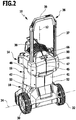
- the drawing shows schematically an inventive high-pressure cleaning device 10 is shown in a position of use, in which a longitudinal axis 12 of the high-pressure cleaning device 10 is vertically aligned.
- the high-pressure cleaning device 10 comprises a housing 14 having an upper housing part 16 and a lower housing part 18, which together surround a motor pump unit 20 with a motor 22 and a pump 24 driven by the motor 22.
- a cleaning liquid preferably water
- the cleaning liquid may be supplied to the pump 24 via a suction port 26, and the cleaning liquid pressurized by the pump 24 may be discharged from the pump 24 via a pressure port 28.
- a suction line preferably a suction hose can be connected, and to the pressure port 28, a pressure line, such as a pressure hose can be connected.
- two wheels 30, 32 are rotatably mounted on the lower housing part 18.
- the high-pressure cleaning device 10 can be moved along on a floor surface.
- the high-pressure cleaning device 10 starting from its in FIG. 1 shown use position in which the longitudinal axis 12 is vertically aligned to a common axis of rotation 34 of the two wheels 30, 32 are pivoted, so that the high-pressure cleaning device 10 can then be moved in the manner of a sack truck.
- the high-pressure cleaner 10 has a U-shaped push bar 36 which is disposed between a in FIG. 1 illustrated parking position and an in FIG. 2 shown operating position can be moved back and forth.
- the push bar 36 has a first leg 37 and a second leg 38, which are rigidly connected to each other via a handle 39.
- the handle 39 takes a greater distance to the housing 14 than in the parking position. This facilitates the user to grasp the handle 39 for moving the high-pressure cleaner 10 in a standing position.
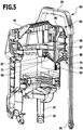
- the upper housing part 16 comprises a first half-shell 41 and a second half-shell 42.
- the two half-shells 41, 42 surround an upper region of the motor pump unit 20 facing the handle 39 in the circumferential direction and are configured essentially mirror-symmetrically with respect to one another. They define therebetween a substantially vertically aligned parting plane 44 in which they meet with their edges facing each other and form a parting line 45 between them.
- the two half-shells 41, 42 each carry a cover part 47 or 48, which is screwed to the respective half-shell 41, 42.
- cover members 47, 48 each one of the Half shells 41 and 42 trained guide channel covered in which a leg 37 and 38 of the push bar 36 is slidably mounted.
- a guide channel 50 is in FIG. 3 shown schematically.
- the lower housing part 18 In alignment with the guide channels 50, the lower housing part 18 each have a quiver-like receptacle 52, 53. If the push bar 36 assumes its parking position, then an end area of the legs 37, 38 enters each receptacle 52, 53. If the push bar 36 is moved to its operating position, the free ends of the legs 37, 38 emerge from the receptacles 52, 53 and assume a position in the amount of the guide channels 50.
- a first positive locking element 55 and 56 is held, with the aid of the push bar 36 can be locked in its operating position.
- a second positive locking element 57 is held on each leg 37, 38, with the aid of the push bar 36 can be locked in its parking position.
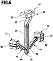
- the high-pressure cleaning device 10 has a locking device 60, which from one in the FIGS. 6 and 7 enlarged illustrated locking unit 62 and one in the Figures 3 and 4 shown return spring 63 is formed.
- the locking unit 62 is designed as a prefabricated unit in the form of a plastic molding. It has an actuator 65 with an actuating head 66 and an integrally adjoining actuating plunger 67, and a first and a second coupling member 69, 70, via which the actuating plunger 67 with a first or with a second locking member 72, 73 is pivotally connected.
- the two coupling members 69, 70 are identical.
- the first coupling member 69 has a first end 75 and a second end 76 and the second coupling member 70 has a first end 78 and a second end 79.
- the first coupling member 69 is followed by a first film hinge 81, via which the first coupling member 69 with the actuating plunger 67 is integrally and hingedly connected.
- a second film hinge 82 connects, via which the first coupling member 69 is integrally and hingedly connected to the first locking member 72.
- a third living hinge 84 adjoining the first end 78 of the second coupling member 70 is a third living hinge 84, via which the second coupling member 70 is integrally and hingedly connected to the actuating plunger 67, and the second end 79 of the second coupling member 70 is followed by a fourth Film hinge 85, via which the second coupling member 70 is integrally and hingedly connected to the second locking member 73.
- the first half-shell 41 forms one in the FIGS. 4 and 5 recognizable guide channel 87 for the first locking member 72, and in an identical manner, the second half-shell 42 forms a not visible in the drawing guide channel for the second locking member 73 from.
- the two half-shells 41 and 42 each form a channel half 90a or 90b of a common guide channel 90, which receives the actuating head 66 and a guide section 92 of the actuating tappet 67 directly adjoining the actuating head 66. This is especially true of the FIGS. 4 and 5 clear.
- the actuating plunger 67 carries on its side facing away from the actuating head 66 lower end of a retaining pin 95 on which the return spring formed as a helical spring 63 is fixed.
- the return spring 63 occupies a position in a spring receptacle, which is formed by the two half-shells 41, 42 and which is aligned with the common guide channel 90.
- the return spring 63 exerts on the actuating plunger 67 a vertically upward spring force, which is transmitted via the coupling members 69, 70 to the locking members 72, 73. Due to the resilient restoring force, the locking members 72, 73 are pressed against the legs 37 and 38 of the push bar 36.
- the locking members 72, 73 each have a U-shaped locking receptacle 97, 98, which faces a leg 37 and 38, respectively. If the push bar 36 assumes its operating position, then the latching receptacles 97, 98 each interact positively with a corresponding latching projection of the first form-locking elements 55, 56. As a result, the push bar 36 can be locked in its operating position.
- the detent receptacles 97, 98 each interact with a corresponding latching projection of the second form-fit elements 57 in a form-fitting manner. As a result, the push bar 36 can be locked in its parking position.
- the user actuates the actuating member 65, wherein he pushes the actuating head 66 and with this the actuating plunger 67 along a first sliding axis 101 vertically downward against the action of the return spring 63.
- the guide portion 92 of the actuating plunger 67 is thereby displaced in the guide channel 90 along the first sliding axis 101.
- the movement of the actuating plunger 67 along the first sliding axis 101 vertically downward against the action of the return spring 63 has the result that the two locking members 72, 73 in the guide channels 87 along a second sliding axis 102, which is aligned perpendicular to the first sliding axis 101, on be moved towards each other, so that the locking members 72, 73 occupy a distance to the form-locking elements 55, 56 and 57 and release them. As a result, the locking of the push bar 36 is released. Subsequently, the user can move the push bar 36.
- the locking members 72, 73 By actuating the actuating member 65, thus, the locking members 72, 73, starting from their locking position, in which they with the interlocking elements 55, 56 and 57 form a positive connection, are moved against the action of the return spring 63 in a release position in which they release the positive-locking elements 55, 56 and 57 respectively.
- the locking members 72, 73 are acted upon by the return spring 63 with a spring force, under the action of which they automatically assume a position on the legs 37, 38 of the push bracket 36. If the push bar 36 is moved from its parking position to its operating position, then the locking members 72, 73 slide along the legs 37, 38 until they meet the first positive locking elements 55, 56 and under the action of the return spring 63 with the first positive locking elements 55, 56 automatically form a positive connection, so that the push handle 36 is locked in its operating position.
- the locking members 72, 73 slide along the legs 37, 38 until they meet the second positive locking elements 57 and under the action of the return spring 63 with the second positive locking elements 57 automatically form a positive connection, so that the push bar 36 is locked in its parking position.
- the locking of the push bar in the parking position and in the operating position is thus carried out automatically by means of the locking device 60 as soon as the push bar 36 has reached the respective position.
- the user has to operate the actuator 65.
- the locking unit consisting of the actuating member 65, the two coupling members 69, 70, the two locking members 72, 73 and the film hinges 81, 82, 84, 85 is configured in the form of a one-piece plastic molding and forms a prefabricated structural unit. This can be easily mounted on the housing 14 during assembly of the high-pressure cleaning device 10.
- the return spring 63 is placed on the spring holder 95 and in the guide channels 87 of the two half-shells 41, 42 a locking member 72, 73 is inserted in each case.
Landscapes
- Cleaning Implements For Floors, Carpets, Furniture, Walls, And The Like (AREA)
- Mechanical Control Devices (AREA)
- Vehicle Cleaning, Maintenance, Repair, Refitting, And Outriggers (AREA)
Claims (18)
- Appareil de nettoyage haute pression comprenant un carter (14) dans lequel sont agencés un moteur (22) et une pompe (24) entraînée par le moteur (22) pour un liquide de nettoyage, et au moins deux roues (30, 32) montées en rotation et servant à déplacer l'appareil de nettoyage haute pression, un étrier de manoeuvre (36) pouvant être animé d'un mouvement de va-et-vient entre une position d'arrêt et une position de fonctionnement, et un dispositif de blocage (60) pour le blocage libérable de l'étrier de manoeuvre (36) dans la position d'arrêt et/ou dans la position de fonctionnement, le dispositif de blocage (60) comprenant un organe d'actionnement (65) qui est accouplé à au moins un organe de blocage (72, 73) coopérant avec l'étrier de manoeuvre (36) par l'intermédiaire d'au moins un organe d'accouplement (69, 70), lequel organe de blocage peut être déplacé d'une position de blocage dans une position de libération à la suite de l'actionnement de l'organe d'actionnement (65), le dispositif de blocage (60) comportant une unité modulaire préfabriquée (62) qui forme l'organe d'actionnement (65), l'organe ou les organes d'accouplement (69, 70) et l'organe ou les organes de blocage (72, 73) et qui est montée mobile sur ou dans le carter (14) et l'organe d'actionnement (65) comprenant un poussoir d'actionnement (67), et en ce que l'organe ou les organes d'accouplement (69, 70) comportent une première et une deuxième extrémité (75, 76 ; 78, 79), l'organe d'accouplement étant articulé sur le poussoir d'actionnement (67) par la première extrémité (75 ; 78) et sur un organe de blocage (72, 73) par la deuxième extrémité (76 ; 79), caractérisé en ce que l'organe ou les organes d'accouplement (69, 70) sont reliés d'un seul tenant au poussoir d'actionnement (67) par une charnière pelliculaire côté poussoir (81, 84) et en ce que l'organe ou les organes d'accouplement (69, 70) sont reliés d'un seul tenant à un organe de blocage (72, 73) par l'intermédiaire d'une charnière pelliculaire côté blocage (82, 85).
- Appareil de nettoyage haute pression selon la revendication 1, caractérisé en ce que l'unité modulaire préfabriquée (62) est réalisée sous la forme d'une pièce moulée en matière plastique d'un seul tenant.
- Appareil de nettoyage haute pression selon la revendication 1 ou 2, caractérisé en ce que l'organe d'actionnement (65) et l'organe ou les organes de blocage (72, 73) sont montés coulissants sur le carter (14).
- Appareil de nettoyage haute pression selon la revendication 3, caractérisé en ce que l'organe d'actionnement (65) peut coulisser le long d'un premier axe de coulissement (101) et en ce que l'organe ou les organes de blocage (72, 73) peuvent coulisser le long d'un deuxième axe de coulissement (102), le deuxième axe de coulissement (102) étant orienté à un angle par rapport au premier axe de coulissement (101).
- Appareil de nettoyage haute pression selon la revendication 4, caractérisé en ce que le deuxième axe de coulissement (102) est orienté perpendiculairement au premier axe de coulissement (101).
- Appareil de nettoyage haute pression selon la revendication 4 ou 5, caractérisé en ce que le premier axe de coulissement (101) est orienté parallèlement à un axe longitudinal (12) de l'appareil de nettoyage haute pression (10) orienté verticalement dans une position d'utilisation de l'appareil de nettoyage haute pression (10).
- Appareil de nettoyage haute pression selon l'une quelconque des revendications précédentes, caractérisé en ce que l'organe ou les organes de blocage (72, 73) peuvent être déplacés de la position de blocage vers la position de libération à l'encontre de l'action d'une force de rappel élastique.
- Appareil de nettoyage haute pression selon l'une quelconque des revendications précédentes, caractérisé en ce que l'organe ou les organes de blocage (72, 73) sont reliés par coopération de formes à l'étrier de manoeuvre (36) dans la position de blocage.
- Appareil de nettoyage haute pression selon l'une quelconque des revendications précédentes, caractérisé en ce que l'organe ou les organes de blocage (72, 73) sont encliquetés avec l'étrier de manoeuvre (36) dans la position de blocage.
- Appareil de nettoyage haute pression selon l'une quelconque des revendications précédentes, caractérisé en ce que le carter (14) comprend un premier canal de guidage (90) dans lequel une partie de guidage (92) de l'organe d'actionnement (65) est retenue coulissante.
- Appareil de nettoyage haute pression selon la revendication 10, caractérisé en ce que le carter (14) présente pour chaque organe de blocage (72, 73) un deuxième canal de guidage (87) dans lequel chaque organe de blocage (72, 73) est respectivement monté coulissant.
- Appareil de nettoyage haute pression selon la revendication 11, caractérisé en ce que l'étrier de manoeuvre (36) est en forme de U et comprend deux branches (37, 38) qui sont reliées l'une à l'autre par une poignée (39), et en ce que le carter (14) comprend deux troisièmes canaux de guidage (50) dans lesquels les branches (37, 38) de l'étrier de manoeuvre (36) sont respectivement montées coulissantes.
- Appareil de nettoyage haute pression selon la revendication 12, caractérisé en ce que l'unité modulaire préfabriquée (62) du dispositif de blocage (60) forme deux organes de blocage (72, 73), qui sont reliés de manière articulée à l'organe d'actionnement (65) respectivement par l'intermédiaire d'un organe d'accouplement (69, 70) et qui coopèrent respectivement avec une branche (37, 38) pour le blocage de l'étrier de manoeuvre (36).
- Appareil de nettoyage haute pression selon la revendication 13, caractérisé en ce que les deux organes de blocage (72, 73) sont montés coulissants respectivement dans un canal de guidage (87) du carter (14).
- Appareil de nettoyage haute pression selon la revendication 13 ou 14, caractérisé en ce que les deux organes de blocage (72, 73) peuvent coulisser le long d'un axe de coulissement (102) commun.
- Appareil de nettoyage haute pression selon la revendication 13, 14 ou 15, caractérisé en ce que les deux organes de blocage (72, 73) sont agencés en symétrie spéculaire par rapport à un axe longitudinal de l'organe d'actionnement (65).
- Appareil de nettoyage haute pression selon l'une quelconque des revendications 13 à 16, caractérisé en ce que le carter (14) comprend deux demi-coques (41, 42) dans lesquelles respectivement un organe de blocage (72, 73) est retenu coulissant.
- Appareil de nettoyage haute pression selon la revendication 17, caractérisé en ce que les deux demi-coques (41, 42) forment un canal de guidage (90) dans lequel l'organe d'actionnement (65) est retenu coulissant.
Applications Claiming Priority (1)
| Application Number | Priority Date | Filing Date | Title |
|---|---|---|---|
| PCT/EP2012/072421 WO2014072000A1 (fr) | 2012-11-12 | 2012-11-12 | Nettoyeur haute pression |
Publications (2)
| Publication Number | Publication Date |
|---|---|
| EP2916970A1 EP2916970A1 (fr) | 2015-09-16 |
| EP2916970B1 true EP2916970B1 (fr) | 2018-05-16 |
Family
ID=47221372
Family Applications (1)
| Application Number | Title | Priority Date | Filing Date |
|---|---|---|---|
| EP12790507.3A Active EP2916970B1 (fr) | 2012-11-12 | 2012-11-12 | Appareil de nettoyage haute pression |
Country Status (5)
| Country | Link |
|---|---|
| US (1) | US10112220B2 (fr) |
| EP (1) | EP2916970B1 (fr) |
| CN (1) | CN104684659B (fr) |
| HU (1) | HUE038942T2 (fr) |
| WO (1) | WO2014072000A1 (fr) |
Families Citing this family (5)
| Publication number | Priority date | Publication date | Assignee | Title |
|---|---|---|---|---|
| DE102015111042A1 (de) * | 2015-07-08 | 2017-01-12 | Alfred Kärcher Gmbh & Co. Kg | Waschvorrichtung für eine Fahrzeugwaschanlage und Fahrzeugwaschanlage |
| WO2018219428A1 (fr) * | 2017-05-29 | 2018-12-06 | Alfred Kärcher SE & Co. KG | Appareil de nettoyage haute pression |
| DE102018102012A1 (de) * | 2018-01-30 | 2019-08-01 | Alfred Kärcher SE & Co. KG | Hochdruckreinigungsgerät |
| USD938113S1 (en) * | 2020-06-02 | 2021-12-07 | Shenzhen Gadgetwoo Tech. Co., Ltd. | Washing machine |
| US20230415205A1 (en) * | 2022-06-24 | 2023-12-28 | Honda Motor Co., Ltd. | Motor disposed below pressure pump |
Citations (1)
| Publication number | Priority date | Publication date | Assignee | Title |
|---|---|---|---|---|
| DE202005019979U1 (de) * | 2005-12-14 | 2006-04-13 | Alfred Kärcher Gmbh & Co. Kg | Fahrbares Hochdruckreinigungsgerät |
Family Cites Families (12)
| Publication number | Priority date | Publication date | Assignee | Title |
|---|---|---|---|---|
| DE9100904U1 (fr) | 1991-01-26 | 1991-04-18 | Wap Reinigungssysteme Gmbh & Co, 7919 Bellenberg, De | |
| DE4108775A1 (de) * | 1991-03-18 | 1992-09-24 | Kaercher Gmbh & Co Alfred | Hochdruckreinigungsgeraet |
| US5178404A (en) * | 1992-01-09 | 1993-01-12 | Johnson Chen | Contraction controller for collapsible type contractible baggage cart |
| US5431428A (en) * | 1993-11-09 | 1995-07-11 | Travel Caddy, Inc. | Carrying case assembly with built-in cart |
| DE9403745U1 (de) * | 1994-03-05 | 1994-05-05 | Einhell Hans Ag | Hochdruckreiniger |
| US5713440A (en) * | 1995-07-03 | 1998-02-03 | Chen; Shou-Mao | Positioning and ejecting device for a retractable handle |
| DE29812015U1 (de) * | 1998-07-06 | 1998-10-08 | Lin Ying Ming | Teleskopgriff für Gepäck |
| USD547014S1 (en) * | 2005-10-11 | 2007-07-17 | Jiming Chen | Gasoline driven cleaning machine |
| WO2008124082A1 (fr) * | 2007-04-03 | 2008-10-16 | Faip North America, Inc. | Laveuse à pression améliorée |
| CN201309147Y (zh) * | 2008-11-28 | 2009-09-16 | 浙江安露清洗机有限公司 | 清洗机的伸缩式拉手 |
| CN201472329U (zh) * | 2009-07-06 | 2010-05-19 | 李建芳 | 立式高压清洗机 |
| CN202006184U (zh) * | 2011-03-06 | 2011-10-12 | 宁波富斯乐机械制造有限公司 | 高压清洗机 |
-
2012
- 2012-11-12 CN CN201280076089.9A patent/CN104684659B/zh active Active
- 2012-11-12 HU HUE12790507A patent/HUE038942T2/hu unknown
- 2012-11-12 EP EP12790507.3A patent/EP2916970B1/fr active Active
- 2012-11-12 WO PCT/EP2012/072421 patent/WO2014072000A1/fr active Application Filing
-
2015
- 2015-05-08 US US14/707,789 patent/US10112220B2/en not_active Expired - Fee Related
Patent Citations (1)
| Publication number | Priority date | Publication date | Assignee | Title |
|---|---|---|---|---|
| DE202005019979U1 (de) * | 2005-12-14 | 2006-04-13 | Alfred Kärcher Gmbh & Co. Kg | Fahrbares Hochdruckreinigungsgerät |
Also Published As
| Publication number | Publication date |
|---|---|
| WO2014072000A1 (fr) | 2014-05-15 |
| HUE038942T2 (hu) | 2018-12-28 |
| US10112220B2 (en) | 2018-10-30 |
| CN104684659B (zh) | 2016-08-17 |
| US20150239019A1 (en) | 2015-08-27 |
| EP2916970A1 (fr) | 2015-09-16 |
| CN104684659A (zh) | 2015-06-03 |
Similar Documents
| Publication | Publication Date | Title |
|---|---|---|
| EP2916970B1 (fr) | Appareil de nettoyage haute pression | |
| AT509923B1 (de) | Einzugsvorrichtung zum einziehen eines bewegbar gelagerten möbelteiles | |
| EP2456341B1 (fr) | Dispositif d'adaptation pour un appareil de nettoyage portable et dispositif de nettoyage pourvu d'un dispositif d'adaptation et d'un appareil de nettoyage | |
| DE3032688C2 (fr) | ||
| EP1899116B1 (fr) | Appareil mobile pour nettoyer le sol | |
| DE102004049085A1 (de) | Vorrichtung zum Verriegeln eines Batteriepacks in einer Führung eines Elektrowerkzeugs | |
| AT516391B1 (de) | Ausstoßvorrichtung für ein bewegbares Möbelteil | |
| DE3729257C2 (fr) | ||
| AT521139A4 (de) | Führungssystem zur Führung eines bewegbar gelagerten Türflügels | |
| DE3416485C2 (de) | Ausstelldach für ein Fahrzeug | |
| EP2172141A1 (fr) | Vaisselle de cuisson dotée d'un élément de poignée ou de tige amovible | |
| EP1765134A1 (fr) | Appareil menager a manche reglable | |
| EP4077844A1 (fr) | Dispositif pour guider une porte coulissante ou une porte accordéon | |
| WO2008028762A1 (fr) | Suceur pour sols durs | |
| DE202014104864U1 (de) | Multidirektional öffenbare Armlehne für Fahrzeuge und Fahrzeug | |
| EP3442716B1 (fr) | Dispositif pour la mise sous pression et la distribution d'un liquide de nettoyage | |
| DE102006061196A1 (de) | Bodendüse für Hartböden | |
| DE202005019979U1 (de) | Fahrbares Hochdruckreinigungsgerät | |
| DE102010062840A1 (de) | Windschutzeinrichtung | |
| DE2435250A1 (de) | Ineinandersteckbare bauteile mit sicherheitsverriegelung, insbesondere rohrfoermige bauteile fuer arbeitsgerueste | |
| DE10105847A1 (de) | Mitnahmevorrichtung für ausziehbaren Möbelboden | |
| DE10104105B4 (de) | Verriegelbares Gelenk | |
| CH698538B1 (de) | Gehäuse mit Traggriffen und abnehmbarer Gehäusewand. | |
| EP2640557B1 (fr) | Table de travail, en particulier pour les ateliers | |
| DE102008052147B3 (de) | Spritzgerät |
Legal Events
| Date | Code | Title | Description |
|---|---|---|---|
| PUAI | Public reference made under article 153(3) epc to a published international application that has entered the european phase |
Free format text: ORIGINAL CODE: 0009012 |
|
| 17P | Request for examination filed |
Effective date: 20150429 |
|
| AK | Designated contracting states |
Kind code of ref document: A1 Designated state(s): AL AT BE BG CH CY CZ DE DK EE ES FI FR GB GR HR HU IE IS IT LI LT LU LV MC MK MT NL NO PL PT RO RS SE SI SK SM TR |
|
| AX | Request for extension of the european patent |
Extension state: BA ME |
|
| DAX | Request for extension of the european patent (deleted) | ||
| RIC1 | Information provided on ipc code assigned before grant |
Ipc: B08B 3/02 20060101AFI20171030BHEP |
|
| GRAP | Despatch of communication of intention to grant a patent |
Free format text: ORIGINAL CODE: EPIDOSNIGR1 |
|
| INTG | Intention to grant announced |
Effective date: 20180105 |
|
| GRAS | Grant fee paid |
Free format text: ORIGINAL CODE: EPIDOSNIGR3 |
|
| GRAA | (expected) grant |
Free format text: ORIGINAL CODE: 0009210 |
|
| AK | Designated contracting states |
Kind code of ref document: B1 Designated state(s): AL AT BE BG CH CY CZ DE DK EE ES FI FR GB GR HR HU IE IS IT LI LT LU LV MC MK MT NL NO PL PT RO RS SE SI SK SM TR |
|
| REG | Reference to a national code |
Ref country code: GB Ref legal event code: FG4D Free format text: NOT ENGLISH |
|
| REG | Reference to a national code |
Ref country code: CH Ref legal event code: EP |
|
| REG | Reference to a national code |
Ref country code: IE Ref legal event code: FG4D Free format text: LANGUAGE OF EP DOCUMENT: GERMAN |
|
| REG | Reference to a national code |
Ref country code: DE Ref legal event code: R096 Ref document number: 502012012716 Country of ref document: DE |
|
| REG | Reference to a national code |
Ref country code: AT Ref legal event code: REF Ref document number: 999053 Country of ref document: AT Kind code of ref document: T Effective date: 20180615 |
|
| REG | Reference to a national code |
Ref country code: DE Ref legal event code: R082 Ref document number: 502012012716 Country of ref document: DE Representative=s name: HOEGER, STELLRECHT & PARTNER PATENTANWAELTE MB, DE Ref country code: DE Ref legal event code: R081 Ref document number: 502012012716 Country of ref document: DE Owner name: ALFRED KAERCHER SE & CO. KG, DE Free format text: FORMER OWNER: ALFRED KAERCHER GMBH & CO. KG, 71364 WINNENDEN, DE |
|
| RAP2 | Party data changed (patent owner data changed or rights of a patent transferred) |
Owner name: ALFRED KAERCHER SE & CO. KG |
|
| REG | Reference to a national code |
Ref country code: NL Ref legal event code: MP Effective date: 20180516 |
|
| REG | Reference to a national code |
Ref country code: LT Ref legal event code: MG4D |
|
| PG25 | Lapsed in a contracting state [announced via postgrant information from national office to epo] |
Ref country code: ES Free format text: LAPSE BECAUSE OF FAILURE TO SUBMIT A TRANSLATION OF THE DESCRIPTION OR TO PAY THE FEE WITHIN THE PRESCRIBED TIME-LIMIT Effective date: 20180516 Ref country code: NO Free format text: LAPSE BECAUSE OF FAILURE TO SUBMIT A TRANSLATION OF THE DESCRIPTION OR TO PAY THE FEE WITHIN THE PRESCRIBED TIME-LIMIT Effective date: 20180816 Ref country code: LT Free format text: LAPSE BECAUSE OF FAILURE TO SUBMIT A TRANSLATION OF THE DESCRIPTION OR TO PAY THE FEE WITHIN THE PRESCRIBED TIME-LIMIT Effective date: 20180516 Ref country code: SE Free format text: LAPSE BECAUSE OF FAILURE TO SUBMIT A TRANSLATION OF THE DESCRIPTION OR TO PAY THE FEE WITHIN THE PRESCRIBED TIME-LIMIT Effective date: 20180516 Ref country code: FI Free format text: LAPSE BECAUSE OF FAILURE TO SUBMIT A TRANSLATION OF THE DESCRIPTION OR TO PAY THE FEE WITHIN THE PRESCRIBED TIME-LIMIT Effective date: 20180516 Ref country code: BG Free format text: LAPSE BECAUSE OF FAILURE TO SUBMIT A TRANSLATION OF THE DESCRIPTION OR TO PAY THE FEE WITHIN THE PRESCRIBED TIME-LIMIT Effective date: 20180816 |
|
| PG25 | Lapsed in a contracting state [announced via postgrant information from national office to epo] |
Ref country code: NL Free format text: LAPSE BECAUSE OF FAILURE TO SUBMIT A TRANSLATION OF THE DESCRIPTION OR TO PAY THE FEE WITHIN THE PRESCRIBED TIME-LIMIT Effective date: 20180516 Ref country code: RS Free format text: LAPSE BECAUSE OF FAILURE TO SUBMIT A TRANSLATION OF THE DESCRIPTION OR TO PAY THE FEE WITHIN THE PRESCRIBED TIME-LIMIT Effective date: 20180516 Ref country code: LV Free format text: LAPSE BECAUSE OF FAILURE TO SUBMIT A TRANSLATION OF THE DESCRIPTION OR TO PAY THE FEE WITHIN THE PRESCRIBED TIME-LIMIT Effective date: 20180516 Ref country code: HR Free format text: LAPSE BECAUSE OF FAILURE TO SUBMIT A TRANSLATION OF THE DESCRIPTION OR TO PAY THE FEE WITHIN THE PRESCRIBED TIME-LIMIT Effective date: 20180516 Ref country code: GR Free format text: LAPSE BECAUSE OF FAILURE TO SUBMIT A TRANSLATION OF THE DESCRIPTION OR TO PAY THE FEE WITHIN THE PRESCRIBED TIME-LIMIT Effective date: 20180817 |
|
| REG | Reference to a national code |
Ref country code: HU Ref legal event code: AG4A Ref document number: E038942 Country of ref document: HU |
|
| PG25 | Lapsed in a contracting state [announced via postgrant information from national office to epo] |
Ref country code: SK Free format text: LAPSE BECAUSE OF FAILURE TO SUBMIT A TRANSLATION OF THE DESCRIPTION OR TO PAY THE FEE WITHIN THE PRESCRIBED TIME-LIMIT Effective date: 20180516 Ref country code: RO Free format text: LAPSE BECAUSE OF FAILURE TO SUBMIT A TRANSLATION OF THE DESCRIPTION OR TO PAY THE FEE WITHIN THE PRESCRIBED TIME-LIMIT Effective date: 20180516 Ref country code: EE Free format text: LAPSE BECAUSE OF FAILURE TO SUBMIT A TRANSLATION OF THE DESCRIPTION OR TO PAY THE FEE WITHIN THE PRESCRIBED TIME-LIMIT Effective date: 20180516 Ref country code: DK Free format text: LAPSE BECAUSE OF FAILURE TO SUBMIT A TRANSLATION OF THE DESCRIPTION OR TO PAY THE FEE WITHIN THE PRESCRIBED TIME-LIMIT Effective date: 20180516 Ref country code: PL Free format text: LAPSE BECAUSE OF FAILURE TO SUBMIT A TRANSLATION OF THE DESCRIPTION OR TO PAY THE FEE WITHIN THE PRESCRIBED TIME-LIMIT Effective date: 20180516 Ref country code: CZ Free format text: LAPSE BECAUSE OF FAILURE TO SUBMIT A TRANSLATION OF THE DESCRIPTION OR TO PAY THE FEE WITHIN THE PRESCRIBED TIME-LIMIT Effective date: 20180516 |
|
| REG | Reference to a national code |
Ref country code: DE Ref legal event code: R097 Ref document number: 502012012716 Country of ref document: DE |
|
| PG25 | Lapsed in a contracting state [announced via postgrant information from national office to epo] |
Ref country code: SM Free format text: LAPSE BECAUSE OF FAILURE TO SUBMIT A TRANSLATION OF THE DESCRIPTION OR TO PAY THE FEE WITHIN THE PRESCRIBED TIME-LIMIT Effective date: 20180516 |
|
| PLBE | No opposition filed within time limit |
Free format text: ORIGINAL CODE: 0009261 |
|
| STAA | Information on the status of an ep patent application or granted ep patent |
Free format text: STATUS: NO OPPOSITION FILED WITHIN TIME LIMIT |
|
| 26N | No opposition filed |
Effective date: 20190219 |
|
| PG25 | Lapsed in a contracting state [announced via postgrant information from national office to epo] |
Ref country code: SI Free format text: LAPSE BECAUSE OF FAILURE TO SUBMIT A TRANSLATION OF THE DESCRIPTION OR TO PAY THE FEE WITHIN THE PRESCRIBED TIME-LIMIT Effective date: 20180516 |
|
| REG | Reference to a national code |
Ref country code: CH Ref legal event code: PL |
|
| GBPC | Gb: european patent ceased through non-payment of renewal fee |
Effective date: 20181112 |
|
| PG25 | Lapsed in a contracting state [announced via postgrant information from national office to epo] |
Ref country code: MC Free format text: LAPSE BECAUSE OF FAILURE TO SUBMIT A TRANSLATION OF THE DESCRIPTION OR TO PAY THE FEE WITHIN THE PRESCRIBED TIME-LIMIT Effective date: 20180516 Ref country code: LU Free format text: LAPSE BECAUSE OF NON-PAYMENT OF DUE FEES Effective date: 20181112 |
|
| REG | Reference to a national code |
Ref country code: BE Ref legal event code: MM Effective date: 20181130 |
|
| REG | Reference to a national code |
Ref country code: IE Ref legal event code: MM4A |
|
| PG25 | Lapsed in a contracting state [announced via postgrant information from national office to epo] |
Ref country code: LI Free format text: LAPSE BECAUSE OF NON-PAYMENT OF DUE FEES Effective date: 20181130 Ref country code: CH Free format text: LAPSE BECAUSE OF NON-PAYMENT OF DUE FEES Effective date: 20181130 |
|
| PG25 | Lapsed in a contracting state [announced via postgrant information from national office to epo] |
Ref country code: FR Free format text: LAPSE BECAUSE OF NON-PAYMENT OF DUE FEES Effective date: 20181130 Ref country code: IE Free format text: LAPSE BECAUSE OF NON-PAYMENT OF DUE FEES Effective date: 20181112 |
|
| PG25 | Lapsed in a contracting state [announced via postgrant information from national office to epo] |
Ref country code: AL Free format text: LAPSE BECAUSE OF FAILURE TO SUBMIT A TRANSLATION OF THE DESCRIPTION OR TO PAY THE FEE WITHIN THE PRESCRIBED TIME-LIMIT Effective date: 20180516 Ref country code: BE Free format text: LAPSE BECAUSE OF NON-PAYMENT OF DUE FEES Effective date: 20181130 |
|
| PG25 | Lapsed in a contracting state [announced via postgrant information from national office to epo] |
Ref country code: GB Free format text: LAPSE BECAUSE OF NON-PAYMENT OF DUE FEES Effective date: 20181112 |
|
| REG | Reference to a national code |
Ref country code: AT Ref legal event code: MM01 Ref document number: 999053 Country of ref document: AT Kind code of ref document: T Effective date: 20181112 |
|
| PG25 | Lapsed in a contracting state [announced via postgrant information from national office to epo] |
Ref country code: AT Free format text: LAPSE BECAUSE OF NON-PAYMENT OF DUE FEES Effective date: 20181112 Ref country code: MT Free format text: LAPSE BECAUSE OF FAILURE TO SUBMIT A TRANSLATION OF THE DESCRIPTION OR TO PAY THE FEE WITHIN THE PRESCRIBED TIME-LIMIT Effective date: 20180516 |
|
| PG25 | Lapsed in a contracting state [announced via postgrant information from national office to epo] |
Ref country code: TR Free format text: LAPSE BECAUSE OF FAILURE TO SUBMIT A TRANSLATION OF THE DESCRIPTION OR TO PAY THE FEE WITHIN THE PRESCRIBED TIME-LIMIT Effective date: 20180516 |
|
| PG25 | Lapsed in a contracting state [announced via postgrant information from national office to epo] |
Ref country code: PT Free format text: LAPSE BECAUSE OF FAILURE TO SUBMIT A TRANSLATION OF THE DESCRIPTION OR TO PAY THE FEE WITHIN THE PRESCRIBED TIME-LIMIT Effective date: 20180516 |
|
| PG25 | Lapsed in a contracting state [announced via postgrant information from national office to epo] |
Ref country code: MK Free format text: LAPSE BECAUSE OF NON-PAYMENT OF DUE FEES Effective date: 20180516 Ref country code: CY Free format text: LAPSE BECAUSE OF FAILURE TO SUBMIT A TRANSLATION OF THE DESCRIPTION OR TO PAY THE FEE WITHIN THE PRESCRIBED TIME-LIMIT Effective date: 20180516 |
|
| PG25 | Lapsed in a contracting state [announced via postgrant information from national office to epo] |
Ref country code: IS Free format text: LAPSE BECAUSE OF FAILURE TO SUBMIT A TRANSLATION OF THE DESCRIPTION OR TO PAY THE FEE WITHIN THE PRESCRIBED TIME-LIMIT Effective date: 20180916 |
|
| P01 | Opt-out of the competence of the unified patent court (upc) registered |
Effective date: 20230521 |
|
| PGFP | Annual fee paid to national office [announced via postgrant information from national office to epo] |
Ref country code: IT Payment date: 20231010 Year of fee payment: 12 Ref country code: HU Payment date: 20231009 Year of fee payment: 12 Ref country code: DE Payment date: 20231127 Year of fee payment: 12 |