EP2913512A1 - Method for processing liquefied gas in ship - Google Patents
Method for processing liquefied gas in ship Download PDFInfo
- Publication number
- EP2913512A1 EP2913512A1 EP13849580.9A EP13849580A EP2913512A1 EP 2913512 A1 EP2913512 A1 EP 2913512A1 EP 13849580 A EP13849580 A EP 13849580A EP 2913512 A1 EP2913512 A1 EP 2913512A1
- Authority
- EP
- European Patent Office
- Prior art keywords
- bog
- engine
- lng
- fuel
- cargo tank
- Prior art date
- Legal status (The legal status is an assumption and is not a legal conclusion. Google has not performed a legal analysis and makes no representation as to the accuracy of the status listed.)
- Granted
Links
- 238000000034 method Methods 0.000 title claims abstract description 55
- 239000003949 liquefied natural gas Substances 0.000 claims abstract description 234
- 239000007789 gas Substances 0.000 claims abstract description 157
- 239000000446 fuel Substances 0.000 claims abstract description 135
- VNWKTOKETHGBQD-UHFFFAOYSA-N methane Chemical compound C VNWKTOKETHGBQD-UHFFFAOYSA-N 0.000 claims description 142
- 230000006835 compression Effects 0.000 claims description 31
- 238000007906 compression Methods 0.000 claims description 31
- 239000004215 Carbon black (E152) Substances 0.000 claims description 7
- 229930195733 hydrocarbon Natural products 0.000 claims description 7
- 150000002430 hydrocarbons Chemical class 0.000 claims description 7
- 239000003345 natural gas Substances 0.000 description 39
- 239000007788 liquid Substances 0.000 description 38
- 230000004048 modification Effects 0.000 description 27
- 238000012986 modification Methods 0.000 description 27
- 239000003507 refrigerant Substances 0.000 description 27
- 239000002737 fuel gas Substances 0.000 description 26
- 238000002347 injection Methods 0.000 description 23
- 239000007924 injection Substances 0.000 description 23
- 238000010586 diagram Methods 0.000 description 19
- MWUXSHHQAYIFBG-UHFFFAOYSA-N nitrogen oxide Inorganic materials O=[N] MWUXSHHQAYIFBG-UHFFFAOYSA-N 0.000 description 18
- IJGRMHOSHXDMSA-UHFFFAOYSA-N Atomic nitrogen Chemical compound N#N IJGRMHOSHXDMSA-UHFFFAOYSA-N 0.000 description 15
- 239000006200 vaporizer Substances 0.000 description 14
- 238000009434 installation Methods 0.000 description 11
- 238000005057 refrigeration Methods 0.000 description 11
- 238000010438 heat treatment Methods 0.000 description 10
- 230000008016 vaporization Effects 0.000 description 8
- 229910052757 nitrogen Inorganic materials 0.000 description 7
- 238000003860 storage Methods 0.000 description 7
- 238000009834 vaporization Methods 0.000 description 6
- CURLTUGMZLYLDI-UHFFFAOYSA-N Carbon dioxide Chemical compound O=C=O CURLTUGMZLYLDI-UHFFFAOYSA-N 0.000 description 5
- 238000010248 power generation Methods 0.000 description 5
- ATUOYWHBWRKTHZ-UHFFFAOYSA-N Propane Chemical compound CCC ATUOYWHBWRKTHZ-UHFFFAOYSA-N 0.000 description 4
- 238000002485 combustion reaction Methods 0.000 description 4
- 238000001816 cooling Methods 0.000 description 4
- 230000008569 process Effects 0.000 description 4
- 229910052815 sulfur oxide Inorganic materials 0.000 description 4
- 238000011144 upstream manufacturing Methods 0.000 description 4
- 229910002092 carbon dioxide Inorganic materials 0.000 description 3
- 239000001569 carbon dioxide Substances 0.000 description 3
- 238000007599 discharging Methods 0.000 description 3
- 239000011261 inert gas Substances 0.000 description 3
- 239000003915 liquefied petroleum gas Substances 0.000 description 3
- 238000012423 maintenance Methods 0.000 description 3
- XTQHKBHJIVJGKJ-UHFFFAOYSA-N sulfur monoxide Chemical class S=O XTQHKBHJIVJGKJ-UHFFFAOYSA-N 0.000 description 3
- 239000002699 waste material Substances 0.000 description 3
- OTMSDBZUPAUEDD-UHFFFAOYSA-N Ethane Chemical compound CC OTMSDBZUPAUEDD-UHFFFAOYSA-N 0.000 description 2
- 230000002730 additional effect Effects 0.000 description 2
- 239000001273 butane Substances 0.000 description 2
- 230000006837 decompression Effects 0.000 description 2
- 230000002950 deficient Effects 0.000 description 2
- 238000007667 floating Methods 0.000 description 2
- 239000000203 mixture Substances 0.000 description 2
- IJDNQMDRQITEOD-UHFFFAOYSA-N n-butane Chemical compound CCCC IJDNQMDRQITEOD-UHFFFAOYSA-N 0.000 description 2
- OFBQJSOFQDEBGM-UHFFFAOYSA-N n-pentane Natural products CCCCC OFBQJSOFQDEBGM-UHFFFAOYSA-N 0.000 description 2
- 239000001294 propane Substances 0.000 description 2
- 238000007789 sealing Methods 0.000 description 2
- 230000032258 transport Effects 0.000 description 2
- NINIDFKCEFEMDL-UHFFFAOYSA-N Sulfur Chemical compound [S] NINIDFKCEFEMDL-UHFFFAOYSA-N 0.000 description 1
- 239000012159 carrier gas Substances 0.000 description 1
- 230000008859 change Effects 0.000 description 1
- 239000000567 combustion gas Substances 0.000 description 1
- 239000002283 diesel fuel Substances 0.000 description 1
- 229910001873 dinitrogen Inorganic materials 0.000 description 1
- TXKMVPPZCYKFAC-UHFFFAOYSA-N disulfur monoxide Inorganic materials O=S=S TXKMVPPZCYKFAC-UHFFFAOYSA-N 0.000 description 1
- 230000009977 dual effect Effects 0.000 description 1
- 230000000694 effects Effects 0.000 description 1
- 230000005611 electricity Effects 0.000 description 1
- 239000003344 environmental pollutant Substances 0.000 description 1
- 230000006872 improvement Effects 0.000 description 1
- 238000009413 insulation Methods 0.000 description 1
- 238000005304 joining Methods 0.000 description 1
- 230000007257 malfunction Effects 0.000 description 1
- 238000004519 manufacturing process Methods 0.000 description 1
- 229910017464 nitrogen compound Inorganic materials 0.000 description 1
- 150000002830 nitrogen compounds Chemical class 0.000 description 1
- 230000008520 organization Effects 0.000 description 1
- 239000003209 petroleum derivative Substances 0.000 description 1
- 231100000719 pollutant Toxicity 0.000 description 1
- 230000002265 prevention Effects 0.000 description 1
- 238000005086 pumping Methods 0.000 description 1
- 230000009467 reduction Effects 0.000 description 1
- 230000008439 repair process Effects 0.000 description 1
- 238000012827 research and development Methods 0.000 description 1
- 229920006395 saturated elastomer Polymers 0.000 description 1
- 239000000243 solution Substances 0.000 description 1
- 229910052717 sulfur Inorganic materials 0.000 description 1
- 239000011593 sulfur Substances 0.000 description 1
- 150000003464 sulfur compounds Chemical class 0.000 description 1
- 238000012546 transfer Methods 0.000 description 1
Images


Classifications
-
- B—PERFORMING OPERATIONS; TRANSPORTING
- B63—SHIPS OR OTHER WATERBORNE VESSELS; RELATED EQUIPMENT
- B63B—SHIPS OR OTHER WATERBORNE VESSELS; EQUIPMENT FOR SHIPPING
- B63B25/00—Load-accommodating arrangements, e.g. stowing, trimming; Vessels characterised thereby
- B63B25/02—Load-accommodating arrangements, e.g. stowing, trimming; Vessels characterised thereby for bulk goods
- B63B25/08—Load-accommodating arrangements, e.g. stowing, trimming; Vessels characterised thereby for bulk goods fluid
- B63B25/12—Load-accommodating arrangements, e.g. stowing, trimming; Vessels characterised thereby for bulk goods fluid closed
- B63B25/16—Load-accommodating arrangements, e.g. stowing, trimming; Vessels characterised thereby for bulk goods fluid closed heat-insulated
-
- B—PERFORMING OPERATIONS; TRANSPORTING
- B63—SHIPS OR OTHER WATERBORNE VESSELS; RELATED EQUIPMENT
- B63H—MARINE PROPULSION OR STEERING
- B63H21/00—Use of propulsion power plant or units on vessels
- B63H21/38—Apparatus or methods specially adapted for use on marine vessels, for handling power plant or unit liquids, e.g. lubricants, coolants, fuels or the like
-
- F—MECHANICAL ENGINEERING; LIGHTING; HEATING; WEAPONS; BLASTING
- F17—STORING OR DISTRIBUTING GASES OR LIQUIDS
- F17C—VESSELS FOR CONTAINING OR STORING COMPRESSED, LIQUEFIED OR SOLIDIFIED GASES; FIXED-CAPACITY GAS-HOLDERS; FILLING VESSELS WITH, OR DISCHARGING FROM VESSELS, COMPRESSED, LIQUEFIED, OR SOLIDIFIED GASES
- F17C7/00—Methods or apparatus for discharging liquefied, solidified, or compressed gases from pressure vessels, not covered by another subclass
- F17C7/02—Discharging liquefied gases
- F17C7/04—Discharging liquefied gases with change of state, e.g. vaporisation
-
- B—PERFORMING OPERATIONS; TRANSPORTING
- B63—SHIPS OR OTHER WATERBORNE VESSELS; RELATED EQUIPMENT
- B63B—SHIPS OR OTHER WATERBORNE VESSELS; EQUIPMENT FOR SHIPPING
- B63B25/00—Load-accommodating arrangements, e.g. stowing, trimming; Vessels characterised thereby
- B63B25/02—Load-accommodating arrangements, e.g. stowing, trimming; Vessels characterised thereby for bulk goods
- B63B25/08—Load-accommodating arrangements, e.g. stowing, trimming; Vessels characterised thereby for bulk goods fluid
- B63B25/12—Load-accommodating arrangements, e.g. stowing, trimming; Vessels characterised thereby for bulk goods fluid closed
- B63B25/14—Load-accommodating arrangements, e.g. stowing, trimming; Vessels characterised thereby for bulk goods fluid closed pressurised
-
- B—PERFORMING OPERATIONS; TRANSPORTING
- B63—SHIPS OR OTHER WATERBORNE VESSELS; RELATED EQUIPMENT
- B63H—MARINE PROPULSION OR STEERING
- B63H21/00—Use of propulsion power plant or units on vessels
-
- B—PERFORMING OPERATIONS; TRANSPORTING
- B63—SHIPS OR OTHER WATERBORNE VESSELS; RELATED EQUIPMENT
- B63H—MARINE PROPULSION OR STEERING
- B63H21/00—Use of propulsion power plant or units on vessels
- B63H21/12—Use of propulsion power plant or units on vessels the vessels being motor-driven
-
- F—MECHANICAL ENGINEERING; LIGHTING; HEATING; WEAPONS; BLASTING
- F02—COMBUSTION ENGINES; HOT-GAS OR COMBUSTION-PRODUCT ENGINE PLANTS
- F02D—CONTROLLING COMBUSTION ENGINES
- F02D19/00—Controlling engines characterised by their use of non-liquid fuels, pluralities of fuels, or non-fuel substances added to the combustible mixtures
- F02D19/06—Controlling engines characterised by their use of non-liquid fuels, pluralities of fuels, or non-fuel substances added to the combustible mixtures peculiar to engines working with pluralities of fuels, e.g. alternatively with light and heavy fuel oil, other than engines indifferent to the fuel consumed
-
- F—MECHANICAL ENGINEERING; LIGHTING; HEATING; WEAPONS; BLASTING
- F02—COMBUSTION ENGINES; HOT-GAS OR COMBUSTION-PRODUCT ENGINE PLANTS
- F02M—SUPPLYING COMBUSTION ENGINES IN GENERAL WITH COMBUSTIBLE MIXTURES OR CONSTITUENTS THEREOF
- F02M21/00—Apparatus for supplying engines with non-liquid fuels, e.g. gaseous fuels stored in liquid form
- F02M21/02—Apparatus for supplying engines with non-liquid fuels, e.g. gaseous fuels stored in liquid form for gaseous fuels
- F02M21/0203—Apparatus for supplying engines with non-liquid fuels, e.g. gaseous fuels stored in liquid form for gaseous fuels characterised by the type of gaseous fuel
- F02M21/0209—Hydrocarbon fuels, e.g. methane or acetylene
- F02M21/0212—Hydrocarbon fuels, e.g. methane or acetylene comprising at least 3 C-Atoms, e.g. liquefied petroleum gas [LPG], propane or butane
-
- F—MECHANICAL ENGINEERING; LIGHTING; HEATING; WEAPONS; BLASTING
- F02—COMBUSTION ENGINES; HOT-GAS OR COMBUSTION-PRODUCT ENGINE PLANTS
- F02M—SUPPLYING COMBUSTION ENGINES IN GENERAL WITH COMBUSTIBLE MIXTURES OR CONSTITUENTS THEREOF
- F02M21/00—Apparatus for supplying engines with non-liquid fuels, e.g. gaseous fuels stored in liquid form
- F02M21/02—Apparatus for supplying engines with non-liquid fuels, e.g. gaseous fuels stored in liquid form for gaseous fuels
- F02M21/0203—Apparatus for supplying engines with non-liquid fuels, e.g. gaseous fuels stored in liquid form for gaseous fuels characterised by the type of gaseous fuel
- F02M21/0215—Mixtures of gaseous fuels; Natural gas; Biogas; Mine gas; Landfill gas
-
- F—MECHANICAL ENGINEERING; LIGHTING; HEATING; WEAPONS; BLASTING
- F02—COMBUSTION ENGINES; HOT-GAS OR COMBUSTION-PRODUCT ENGINE PLANTS
- F02M—SUPPLYING COMBUSTION ENGINES IN GENERAL WITH COMBUSTIBLE MIXTURES OR CONSTITUENTS THEREOF
- F02M21/00—Apparatus for supplying engines with non-liquid fuels, e.g. gaseous fuels stored in liquid form
- F02M21/02—Apparatus for supplying engines with non-liquid fuels, e.g. gaseous fuels stored in liquid form for gaseous fuels
- F02M21/0218—Details on the gaseous fuel supply system, e.g. tanks, valves, pipes, pumps, rails, injectors or mixers
- F02M21/0221—Fuel storage reservoirs, e.g. cryogenic tanks
-
- F—MECHANICAL ENGINEERING; LIGHTING; HEATING; WEAPONS; BLASTING
- F02—COMBUSTION ENGINES; HOT-GAS OR COMBUSTION-PRODUCT ENGINE PLANTS
- F02M—SUPPLYING COMBUSTION ENGINES IN GENERAL WITH COMBUSTIBLE MIXTURES OR CONSTITUENTS THEREOF
- F02M21/00—Apparatus for supplying engines with non-liquid fuels, e.g. gaseous fuels stored in liquid form
- F02M21/02—Apparatus for supplying engines with non-liquid fuels, e.g. gaseous fuels stored in liquid form for gaseous fuels
- F02M21/0218—Details on the gaseous fuel supply system, e.g. tanks, valves, pipes, pumps, rails, injectors or mixers
- F02M21/023—Valves; Pressure or flow regulators in the fuel supply or return system
-
- F—MECHANICAL ENGINEERING; LIGHTING; HEATING; WEAPONS; BLASTING
- F02—COMBUSTION ENGINES; HOT-GAS OR COMBUSTION-PRODUCT ENGINE PLANTS
- F02M—SUPPLYING COMBUSTION ENGINES IN GENERAL WITH COMBUSTIBLE MIXTURES OR CONSTITUENTS THEREOF
- F02M21/00—Apparatus for supplying engines with non-liquid fuels, e.g. gaseous fuels stored in liquid form
- F02M21/02—Apparatus for supplying engines with non-liquid fuels, e.g. gaseous fuels stored in liquid form for gaseous fuels
- F02M21/0218—Details on the gaseous fuel supply system, e.g. tanks, valves, pipes, pumps, rails, injectors or mixers
- F02M21/0245—High pressure fuel supply systems; Rails; Pumps; Arrangement of valves
-
- F—MECHANICAL ENGINEERING; LIGHTING; HEATING; WEAPONS; BLASTING
- F02—COMBUSTION ENGINES; HOT-GAS OR COMBUSTION-PRODUCT ENGINE PLANTS
- F02M—SUPPLYING COMBUSTION ENGINES IN GENERAL WITH COMBUSTIBLE MIXTURES OR CONSTITUENTS THEREOF
- F02M21/00—Apparatus for supplying engines with non-liquid fuels, e.g. gaseous fuels stored in liquid form
- F02M21/02—Apparatus for supplying engines with non-liquid fuels, e.g. gaseous fuels stored in liquid form for gaseous fuels
- F02M21/0218—Details on the gaseous fuel supply system, e.g. tanks, valves, pipes, pumps, rails, injectors or mixers
- F02M21/0248—Injectors
-
- F—MECHANICAL ENGINEERING; LIGHTING; HEATING; WEAPONS; BLASTING
- F02—COMBUSTION ENGINES; HOT-GAS OR COMBUSTION-PRODUCT ENGINE PLANTS
- F02M—SUPPLYING COMBUSTION ENGINES IN GENERAL WITH COMBUSTIBLE MIXTURES OR CONSTITUENTS THEREOF
- F02M21/00—Apparatus for supplying engines with non-liquid fuels, e.g. gaseous fuels stored in liquid form
- F02M21/02—Apparatus for supplying engines with non-liquid fuels, e.g. gaseous fuels stored in liquid form for gaseous fuels
- F02M21/0218—Details on the gaseous fuel supply system, e.g. tanks, valves, pipes, pumps, rails, injectors or mixers
- F02M21/0287—Details on the gaseous fuel supply system, e.g. tanks, valves, pipes, pumps, rails, injectors or mixers characterised by the transition from liquid to gaseous phase ; Injection in liquid phase; Cooling and low temperature storage
-
- F—MECHANICAL ENGINEERING; LIGHTING; HEATING; WEAPONS; BLASTING
- F02—COMBUSTION ENGINES; HOT-GAS OR COMBUSTION-PRODUCT ENGINE PLANTS
- F02M—SUPPLYING COMBUSTION ENGINES IN GENERAL WITH COMBUSTIBLE MIXTURES OR CONSTITUENTS THEREOF
- F02M31/00—Apparatus for thermally treating combustion-air, fuel, or fuel-air mixture
- F02M31/02—Apparatus for thermally treating combustion-air, fuel, or fuel-air mixture for heating
- F02M31/16—Other apparatus for heating fuel
-
- F—MECHANICAL ENGINEERING; LIGHTING; HEATING; WEAPONS; BLASTING
- F02—COMBUSTION ENGINES; HOT-GAS OR COMBUSTION-PRODUCT ENGINE PLANTS
- F02M—SUPPLYING COMBUSTION ENGINES IN GENERAL WITH COMBUSTIBLE MIXTURES OR CONSTITUENTS THEREOF
- F02M37/00—Apparatus or systems for feeding liquid fuel from storage containers to carburettors or fuel-injection apparatus; Arrangements for purifying liquid fuel specially adapted for, or arranged on, internal-combustion engines
- F02M37/04—Feeding by means of driven pumps
-
- F—MECHANICAL ENGINEERING; LIGHTING; HEATING; WEAPONS; BLASTING
- F17—STORING OR DISTRIBUTING GASES OR LIQUIDS
- F17C—VESSELS FOR CONTAINING OR STORING COMPRESSED, LIQUEFIED OR SOLIDIFIED GASES; FIXED-CAPACITY GAS-HOLDERS; FILLING VESSELS WITH, OR DISCHARGING FROM VESSELS, COMPRESSED, LIQUEFIED, OR SOLIDIFIED GASES
- F17C1/00—Pressure vessels, e.g. gas cylinder, gas tank, replaceable cartridge
- F17C1/002—Storage in barges or on ships
-
- F—MECHANICAL ENGINEERING; LIGHTING; HEATING; WEAPONS; BLASTING
- F17—STORING OR DISTRIBUTING GASES OR LIQUIDS
- F17C—VESSELS FOR CONTAINING OR STORING COMPRESSED, LIQUEFIED OR SOLIDIFIED GASES; FIXED-CAPACITY GAS-HOLDERS; FILLING VESSELS WITH, OR DISCHARGING FROM VESSELS, COMPRESSED, LIQUEFIED, OR SOLIDIFIED GASES
- F17C13/00—Details of vessels or of the filling or discharging of vessels
- F17C13/08—Mounting arrangements for vessels
- F17C13/082—Mounting arrangements for vessels for large sea-borne storage vessels
-
- F—MECHANICAL ENGINEERING; LIGHTING; HEATING; WEAPONS; BLASTING
- F17—STORING OR DISTRIBUTING GASES OR LIQUIDS
- F17C—VESSELS FOR CONTAINING OR STORING COMPRESSED, LIQUEFIED OR SOLIDIFIED GASES; FIXED-CAPACITY GAS-HOLDERS; FILLING VESSELS WITH, OR DISCHARGING FROM VESSELS, COMPRESSED, LIQUEFIED, OR SOLIDIFIED GASES
- F17C7/00—Methods or apparatus for discharging liquefied, solidified, or compressed gases from pressure vessels, not covered by another subclass
- F17C7/02—Discharging liquefied gases
-
- F—MECHANICAL ENGINEERING; LIGHTING; HEATING; WEAPONS; BLASTING
- F17—STORING OR DISTRIBUTING GASES OR LIQUIDS
- F17C—VESSELS FOR CONTAINING OR STORING COMPRESSED, LIQUEFIED OR SOLIDIFIED GASES; FIXED-CAPACITY GAS-HOLDERS; FILLING VESSELS WITH, OR DISCHARGING FROM VESSELS, COMPRESSED, LIQUEFIED, OR SOLIDIFIED GASES
- F17C9/00—Methods or apparatus for discharging liquefied or solidified gases from vessels not under pressure
- F17C9/02—Methods or apparatus for discharging liquefied or solidified gases from vessels not under pressure with change of state, e.g. vaporisation
-
- F—MECHANICAL ENGINEERING; LIGHTING; HEATING; WEAPONS; BLASTING
- F25—REFRIGERATION OR COOLING; COMBINED HEATING AND REFRIGERATION SYSTEMS; HEAT PUMP SYSTEMS; MANUFACTURE OR STORAGE OF ICE; LIQUEFACTION SOLIDIFICATION OF GASES
- F25J—LIQUEFACTION, SOLIDIFICATION OR SEPARATION OF GASES OR GASEOUS OR LIQUEFIED GASEOUS MIXTURES BY PRESSURE AND COLD TREATMENT OR BY BRINGING THEM INTO THE SUPERCRITICAL STATE
- F25J1/00—Processes or apparatus for liquefying or solidifying gases or gaseous mixtures
- F25J1/0002—Processes or apparatus for liquefying or solidifying gases or gaseous mixtures characterised by the fluid to be liquefied
- F25J1/0022—Hydrocarbons, e.g. natural gas
- F25J1/0025—Boil-off gases "BOG" from storages
-
- F—MECHANICAL ENGINEERING; LIGHTING; HEATING; WEAPONS; BLASTING
- F25—REFRIGERATION OR COOLING; COMBINED HEATING AND REFRIGERATION SYSTEMS; HEAT PUMP SYSTEMS; MANUFACTURE OR STORAGE OF ICE; LIQUEFACTION SOLIDIFICATION OF GASES
- F25J—LIQUEFACTION, SOLIDIFICATION OR SEPARATION OF GASES OR GASEOUS OR LIQUEFIED GASEOUS MIXTURES BY PRESSURE AND COLD TREATMENT OR BY BRINGING THEM INTO THE SUPERCRITICAL STATE
- F25J1/00—Processes or apparatus for liquefying or solidifying gases or gaseous mixtures
- F25J1/003—Processes or apparatus for liquefying or solidifying gases or gaseous mixtures characterised by the kind of cold generation within the liquefaction unit for compensating heat leaks and liquid production
- F25J1/0032—Processes or apparatus for liquefying or solidifying gases or gaseous mixtures characterised by the kind of cold generation within the liquefaction unit for compensating heat leaks and liquid production using the feed stream itself or separated fractions from it, i.e. "internal refrigeration"
- F25J1/004—Processes or apparatus for liquefying or solidifying gases or gaseous mixtures characterised by the kind of cold generation within the liquefaction unit for compensating heat leaks and liquid production using the feed stream itself or separated fractions from it, i.e. "internal refrigeration" by flash gas recovery
-
- F—MECHANICAL ENGINEERING; LIGHTING; HEATING; WEAPONS; BLASTING
- F25—REFRIGERATION OR COOLING; COMBINED HEATING AND REFRIGERATION SYSTEMS; HEAT PUMP SYSTEMS; MANUFACTURE OR STORAGE OF ICE; LIQUEFACTION SOLIDIFICATION OF GASES
- F25J—LIQUEFACTION, SOLIDIFICATION OR SEPARATION OF GASES OR GASEOUS OR LIQUEFIED GASEOUS MIXTURES BY PRESSURE AND COLD TREATMENT OR BY BRINGING THEM INTO THE SUPERCRITICAL STATE
- F25J1/00—Processes or apparatus for liquefying or solidifying gases or gaseous mixtures
- F25J1/003—Processes or apparatus for liquefying or solidifying gases or gaseous mixtures characterised by the kind of cold generation within the liquefaction unit for compensating heat leaks and liquid production
- F25J1/0032—Processes or apparatus for liquefying or solidifying gases or gaseous mixtures characterised by the kind of cold generation within the liquefaction unit for compensating heat leaks and liquid production using the feed stream itself or separated fractions from it, i.e. "internal refrigeration"
- F25J1/0042—Processes or apparatus for liquefying or solidifying gases or gaseous mixtures characterised by the kind of cold generation within the liquefaction unit for compensating heat leaks and liquid production using the feed stream itself or separated fractions from it, i.e. "internal refrigeration" by liquid expansion with extraction of work
-
- F—MECHANICAL ENGINEERING; LIGHTING; HEATING; WEAPONS; BLASTING
- F25—REFRIGERATION OR COOLING; COMBINED HEATING AND REFRIGERATION SYSTEMS; HEAT PUMP SYSTEMS; MANUFACTURE OR STORAGE OF ICE; LIQUEFACTION SOLIDIFICATION OF GASES
- F25J—LIQUEFACTION, SOLIDIFICATION OR SEPARATION OF GASES OR GASEOUS OR LIQUEFIED GASEOUS MIXTURES BY PRESSURE AND COLD TREATMENT OR BY BRINGING THEM INTO THE SUPERCRITICAL STATE
- F25J1/00—Processes or apparatus for liquefying or solidifying gases or gaseous mixtures
- F25J1/02—Processes or apparatus for liquefying or solidifying gases or gaseous mixtures requiring the use of refrigeration, e.g. of helium or hydrogen ; Details and kind of the refrigeration system used; Integration with other units or processes; Controlling aspects of the process
- F25J1/0201—Processes or apparatus for liquefying or solidifying gases or gaseous mixtures requiring the use of refrigeration, e.g. of helium or hydrogen ; Details and kind of the refrigeration system used; Integration with other units or processes; Controlling aspects of the process using only internal refrigeration means, i.e. without external refrigeration
- F25J1/0202—Processes or apparatus for liquefying or solidifying gases or gaseous mixtures requiring the use of refrigeration, e.g. of helium or hydrogen ; Details and kind of the refrigeration system used; Integration with other units or processes; Controlling aspects of the process using only internal refrigeration means, i.e. without external refrigeration in a quasi-closed internal refrigeration loop
-
- F—MECHANICAL ENGINEERING; LIGHTING; HEATING; WEAPONS; BLASTING
- F25—REFRIGERATION OR COOLING; COMBINED HEATING AND REFRIGERATION SYSTEMS; HEAT PUMP SYSTEMS; MANUFACTURE OR STORAGE OF ICE; LIQUEFACTION SOLIDIFICATION OF GASES
- F25J—LIQUEFACTION, SOLIDIFICATION OR SEPARATION OF GASES OR GASEOUS OR LIQUEFIED GASEOUS MIXTURES BY PRESSURE AND COLD TREATMENT OR BY BRINGING THEM INTO THE SUPERCRITICAL STATE
- F25J1/00—Processes or apparatus for liquefying or solidifying gases or gaseous mixtures
- F25J1/02—Processes or apparatus for liquefying or solidifying gases or gaseous mixtures requiring the use of refrigeration, e.g. of helium or hydrogen ; Details and kind of the refrigeration system used; Integration with other units or processes; Controlling aspects of the process
- F25J1/0228—Coupling of the liquefaction unit to other units or processes, so-called integrated processes
- F25J1/0229—Integration with a unit for using hydrocarbons, e.g. consuming hydrocarbons as feed stock
- F25J1/023—Integration with a unit for using hydrocarbons, e.g. consuming hydrocarbons as feed stock for the combustion as fuels, i.e. integration with the fuel gas system
-
- F—MECHANICAL ENGINEERING; LIGHTING; HEATING; WEAPONS; BLASTING
- F25—REFRIGERATION OR COOLING; COMBINED HEATING AND REFRIGERATION SYSTEMS; HEAT PUMP SYSTEMS; MANUFACTURE OR STORAGE OF ICE; LIQUEFACTION SOLIDIFICATION OF GASES
- F25J—LIQUEFACTION, SOLIDIFICATION OR SEPARATION OF GASES OR GASEOUS OR LIQUEFIED GASEOUS MIXTURES BY PRESSURE AND COLD TREATMENT OR BY BRINGING THEM INTO THE SUPERCRITICAL STATE
- F25J1/00—Processes or apparatus for liquefying or solidifying gases or gaseous mixtures
- F25J1/02—Processes or apparatus for liquefying or solidifying gases or gaseous mixtures requiring the use of refrigeration, e.g. of helium or hydrogen ; Details and kind of the refrigeration system used; Integration with other units or processes; Controlling aspects of the process
- F25J1/0243—Start-up or control of the process; Details of the apparatus used; Details of the refrigerant compression system used
- F25J1/0257—Construction and layout of liquefaction equipments, e.g. valves, machines
- F25J1/0275—Construction and layout of liquefaction equipments, e.g. valves, machines adapted for special use of the liquefaction unit, e.g. portable or transportable devices
- F25J1/0277—Offshore use, e.g. during shipping
-
- F—MECHANICAL ENGINEERING; LIGHTING; HEATING; WEAPONS; BLASTING
- F17—STORING OR DISTRIBUTING GASES OR LIQUIDS
- F17C—VESSELS FOR CONTAINING OR STORING COMPRESSED, LIQUEFIED OR SOLIDIFIED GASES; FIXED-CAPACITY GAS-HOLDERS; FILLING VESSELS WITH, OR DISCHARGING FROM VESSELS, COMPRESSED, LIQUEFIED, OR SOLIDIFIED GASES
- F17C2201/00—Vessel construction, in particular geometry, arrangement or size
- F17C2201/01—Shape
- F17C2201/0147—Shape complex
- F17C2201/0157—Polygonal
-
- F—MECHANICAL ENGINEERING; LIGHTING; HEATING; WEAPONS; BLASTING
- F17—STORING OR DISTRIBUTING GASES OR LIQUIDS
- F17C—VESSELS FOR CONTAINING OR STORING COMPRESSED, LIQUEFIED OR SOLIDIFIED GASES; FIXED-CAPACITY GAS-HOLDERS; FILLING VESSELS WITH, OR DISCHARGING FROM VESSELS, COMPRESSED, LIQUEFIED, OR SOLIDIFIED GASES
- F17C2201/00—Vessel construction, in particular geometry, arrangement or size
- F17C2201/05—Size
- F17C2201/052—Size large (>1000 m3)
-
- F—MECHANICAL ENGINEERING; LIGHTING; HEATING; WEAPONS; BLASTING
- F17—STORING OR DISTRIBUTING GASES OR LIQUIDS
- F17C—VESSELS FOR CONTAINING OR STORING COMPRESSED, LIQUEFIED OR SOLIDIFIED GASES; FIXED-CAPACITY GAS-HOLDERS; FILLING VESSELS WITH, OR DISCHARGING FROM VESSELS, COMPRESSED, LIQUEFIED, OR SOLIDIFIED GASES
- F17C2221/00—Handled fluid, in particular type of fluid
- F17C2221/03—Mixtures
- F17C2221/032—Hydrocarbons
- F17C2221/033—Methane, e.g. natural gas, CNG, LNG, GNL, GNC, PLNG
-
- F—MECHANICAL ENGINEERING; LIGHTING; HEATING; WEAPONS; BLASTING
- F17—STORING OR DISTRIBUTING GASES OR LIQUIDS
- F17C—VESSELS FOR CONTAINING OR STORING COMPRESSED, LIQUEFIED OR SOLIDIFIED GASES; FIXED-CAPACITY GAS-HOLDERS; FILLING VESSELS WITH, OR DISCHARGING FROM VESSELS, COMPRESSED, LIQUEFIED, OR SOLIDIFIED GASES
- F17C2223/00—Handled fluid before transfer, i.e. state of fluid when stored in the vessel or before transfer from the vessel
- F17C2223/01—Handled fluid before transfer, i.e. state of fluid when stored in the vessel or before transfer from the vessel characterised by the phase
- F17C2223/0146—Two-phase
- F17C2223/0153—Liquefied gas, e.g. LPG, GPL
- F17C2223/0161—Liquefied gas, e.g. LPG, GPL cryogenic, e.g. LNG, GNL, PLNG
-
- F—MECHANICAL ENGINEERING; LIGHTING; HEATING; WEAPONS; BLASTING
- F17—STORING OR DISTRIBUTING GASES OR LIQUIDS
- F17C—VESSELS FOR CONTAINING OR STORING COMPRESSED, LIQUEFIED OR SOLIDIFIED GASES; FIXED-CAPACITY GAS-HOLDERS; FILLING VESSELS WITH, OR DISCHARGING FROM VESSELS, COMPRESSED, LIQUEFIED, OR SOLIDIFIED GASES
- F17C2223/00—Handled fluid before transfer, i.e. state of fluid when stored in the vessel or before transfer from the vessel
- F17C2223/03—Handled fluid before transfer, i.e. state of fluid when stored in the vessel or before transfer from the vessel characterised by the pressure level
- F17C2223/033—Small pressure, e.g. for liquefied gas
-
- F—MECHANICAL ENGINEERING; LIGHTING; HEATING; WEAPONS; BLASTING
- F17—STORING OR DISTRIBUTING GASES OR LIQUIDS
- F17C—VESSELS FOR CONTAINING OR STORING COMPRESSED, LIQUEFIED OR SOLIDIFIED GASES; FIXED-CAPACITY GAS-HOLDERS; FILLING VESSELS WITH, OR DISCHARGING FROM VESSELS, COMPRESSED, LIQUEFIED, OR SOLIDIFIED GASES
- F17C2265/00—Effects achieved by gas storage or gas handling
- F17C2265/03—Treating the boil-off
- F17C2265/032—Treating the boil-off by recovery
- F17C2265/033—Treating the boil-off by recovery with cooling
- F17C2265/034—Treating the boil-off by recovery with cooling with condensing the gas phase
-
- F—MECHANICAL ENGINEERING; LIGHTING; HEATING; WEAPONS; BLASTING
- F17—STORING OR DISTRIBUTING GASES OR LIQUIDS
- F17C—VESSELS FOR CONTAINING OR STORING COMPRESSED, LIQUEFIED OR SOLIDIFIED GASES; FIXED-CAPACITY GAS-HOLDERS; FILLING VESSELS WITH, OR DISCHARGING FROM VESSELS, COMPRESSED, LIQUEFIED, OR SOLIDIFIED GASES
- F17C2265/00—Effects achieved by gas storage or gas handling
- F17C2265/03—Treating the boil-off
- F17C2265/032—Treating the boil-off by recovery
- F17C2265/037—Treating the boil-off by recovery with pressurising
-
- F—MECHANICAL ENGINEERING; LIGHTING; HEATING; WEAPONS; BLASTING
- F17—STORING OR DISTRIBUTING GASES OR LIQUIDS
- F17C—VESSELS FOR CONTAINING OR STORING COMPRESSED, LIQUEFIED OR SOLIDIFIED GASES; FIXED-CAPACITY GAS-HOLDERS; FILLING VESSELS WITH, OR DISCHARGING FROM VESSELS, COMPRESSED, LIQUEFIED, OR SOLIDIFIED GASES
- F17C2265/00—Effects achieved by gas storage or gas handling
- F17C2265/06—Fluid distribution
- F17C2265/066—Fluid distribution for feeding engines for propulsion
-
- F—MECHANICAL ENGINEERING; LIGHTING; HEATING; WEAPONS; BLASTING
- F17—STORING OR DISTRIBUTING GASES OR LIQUIDS
- F17C—VESSELS FOR CONTAINING OR STORING COMPRESSED, LIQUEFIED OR SOLIDIFIED GASES; FIXED-CAPACITY GAS-HOLDERS; FILLING VESSELS WITH, OR DISCHARGING FROM VESSELS, COMPRESSED, LIQUEFIED, OR SOLIDIFIED GASES
- F17C2270/00—Applications
- F17C2270/01—Applications for fluid transport or storage
- F17C2270/0102—Applications for fluid transport or storage on or in the water
- F17C2270/0105—Ships
- F17C2270/0107—Wall panels
-
- Y—GENERAL TAGGING OF NEW TECHNOLOGICAL DEVELOPMENTS; GENERAL TAGGING OF CROSS-SECTIONAL TECHNOLOGIES SPANNING OVER SEVERAL SECTIONS OF THE IPC; TECHNICAL SUBJECTS COVERED BY FORMER USPC CROSS-REFERENCE ART COLLECTIONS [XRACs] AND DIGESTS
- Y02—TECHNOLOGIES OR APPLICATIONS FOR MITIGATION OR ADAPTATION AGAINST CLIMATE CHANGE
- Y02T—CLIMATE CHANGE MITIGATION TECHNOLOGIES RELATED TO TRANSPORTATION
- Y02T10/00—Road transport of goods or passengers
- Y02T10/10—Internal combustion engine [ICE] based vehicles
- Y02T10/12—Improving ICE efficiencies
-
- Y—GENERAL TAGGING OF NEW TECHNOLOGICAL DEVELOPMENTS; GENERAL TAGGING OF CROSS-SECTIONAL TECHNOLOGIES SPANNING OVER SEVERAL SECTIONS OF THE IPC; TECHNICAL SUBJECTS COVERED BY FORMER USPC CROSS-REFERENCE ART COLLECTIONS [XRACs] AND DIGESTS
- Y02—TECHNOLOGIES OR APPLICATIONS FOR MITIGATION OR ADAPTATION AGAINST CLIMATE CHANGE
- Y02T—CLIMATE CHANGE MITIGATION TECHNOLOGIES RELATED TO TRANSPORTATION
- Y02T10/00—Road transport of goods or passengers
- Y02T10/10—Internal combustion engine [ICE] based vehicles
- Y02T10/30—Use of alternative fuels, e.g. biofuels
-
- Y—GENERAL TAGGING OF NEW TECHNOLOGICAL DEVELOPMENTS; GENERAL TAGGING OF CROSS-SECTIONAL TECHNOLOGIES SPANNING OVER SEVERAL SECTIONS OF THE IPC; TECHNICAL SUBJECTS COVERED BY FORMER USPC CROSS-REFERENCE ART COLLECTIONS [XRACs] AND DIGESTS
- Y02—TECHNOLOGIES OR APPLICATIONS FOR MITIGATION OR ADAPTATION AGAINST CLIMATE CHANGE
- Y02T—CLIMATE CHANGE MITIGATION TECHNOLOGIES RELATED TO TRANSPORTATION
- Y02T70/00—Maritime or waterways transport
- Y02T70/50—Measures to reduce greenhouse gas emissions related to the propulsion system
-
- Y—GENERAL TAGGING OF NEW TECHNOLOGICAL DEVELOPMENTS; GENERAL TAGGING OF CROSS-SECTIONAL TECHNOLOGIES SPANNING OVER SEVERAL SECTIONS OF THE IPC; TECHNICAL SUBJECTS COVERED BY FORMER USPC CROSS-REFERENCE ART COLLECTIONS [XRACs] AND DIGESTS
- Y02—TECHNOLOGIES OR APPLICATIONS FOR MITIGATION OR ADAPTATION AGAINST CLIMATE CHANGE
- Y02T—CLIMATE CHANGE MITIGATION TECHNOLOGIES RELATED TO TRANSPORTATION
- Y02T90/00—Enabling technologies or technologies with a potential or indirect contribution to GHG emissions mitigation
- Y02T90/40—Application of hydrogen technology to transportation, e.g. using fuel cells
Definitions
- the present invention relates to a liquefied gas treatment method for a vessel.
- Liquefied gas such as liquefied natural gas (LNG) or liquefied petroleum gas (LPG)
- LNG liquefied natural gas
- LPG liquefied petroleum gas
- Liquefied gas is transported in a gas state through onshore or offshore gas pipelines, or is transported to a remote consumption place while being stored in a liquefied state inside a liquefied gas carrier.
- Liquefied gas, such as LNG or LPG is obtained by cooling natural gas or petroleum gas to a cryogenic temperature (in the case of LNG, about-163°C). Since the volume of liquefied gas is considerably reduced as compared to a gas state, liquefied gas is very suitable for a long-distance marine transportation.
- a liquefied gas carrier such as an LNG carrier is designed to load liquefied gas, sail across the sea, and unload the liquefied gas at an onshore consumption place.
- the liquefied gas carrier includes a storage tank (also called “cargo tank”) that can withstand a cryogenic temperature of liquefied gas.
- Examples of a marine structure provided with a cargo tank capable of storing cryogenic liquefied gas may include vessels such as a liquefied gas carrier and an LNG Regasification Vessel (LNG RV), or structures such as an LNG Floating Storage and Regasification Unit (LNG FSRU) and an LNG Floating, Production, Storage and Off-loading (LNG FPSO), and a Barge Mounted Power Plant (BMPP).
- vessels such as a liquefied gas carrier and an LNG Regasification Vessel (LNG RV), or structures such as an LNG Floating Storage and Regasification Unit (LNG FSRU) and an LNG Floating, Production, Storage and Off-loading (LNG FPSO), and a Barge Mounted Power Plant (BMPP).
- LNG RV LNG Regasification Vessel
- LNG FSRU LNG Floating Storage and Regasification Unit
- LNG FPSO LNG Floating, Production, Storage and Off-loading
- BMPP Barge Mounte
- the LNG RV is a self-propelled, floatable liquefied gas carrier equipped with an LNG regasification facility
- the LNG FSRU is a marine structure that stores LNG unloaded from an LNG carrier on the sea far away from the land and, if necessary, supplies the LNG to an onshore consumption place by gasifying the LNG.
- the LNG FPSO is a marine structure that refines extracted LNG on the sea, stores the LNG in a storage tank after direct liquefaction, and, if necessary, transships the LNG to an LNG carrier.
- the BMPP is a structure that is equipped with a power generation facility to produce electricity on the sea.
- the term "vessel” as used herein is a concept including a liquefied gas carrier such as an LNG carrier, an LNG RV, and structures such as an LNG FPSO, an LNG FSRU, and a BMPP.
- LNG Since the liquefaction temperature of natural gas is a cryogenic temperature of-163°C at ambient pressure, LNG is likely to be vaporized even when the temperature of LNG is slightly higher than -163 °C at ambient pressure.
- LNG In the case of a conventional LNG carrier, even though an LNG cargo tank is thermally insulated, external heat is continuously transferred to LNG. Therefore, during the transportation of LNG by the LNG carrier, LNG is continuously vaporized within the LNG cargo tank and boil-off gas (hereinafter, referred to as BOG) is generated within the LNG cargo tank.
- BOG boil-off gas
- the generated natural gas may increase the inside pressure of the cargo tank and accelerate the flow of the natural gas due to the rocking of the vessel, causing structural problems. Therefore, it is necessary to suppress the generation of BOG.
- BOG inside a cargo tank is discharged from the cargo tank and then reliquefied through a reliquefaction apparatus in order to maintain a pressure of the cargo tank at an appropriate level.
- the discharged BOG is reliquefied through heat exchange with a refrigerant (for example, nitrogen, mixed refrigerant, or the like) cooled to a cryogenic temperature in the reliquefaction apparatus including a refrigeration cycle, and the reliquefied BOG is returned to the cargo tank.
- a refrigerant for example, nitrogen, mixed refrigerant, or the like
- BOG is consumed in such a manner that it is supplied as fuel to the DFDE after treating BOG by only a BOG compressor and heating, without installing the reliquefaction facility. Therefore, when an amount of fuel necessary for an engine is smaller than a generation amount of BOG, there is a problem that BOG is burnt in a gas combustion unit (GCU) or is vented to atmosphere.
- GCU gas combustion unit
- the present invention has been made in an effort to solve the above problems and is directed to a liquefied gas treatment system and method for a vessel, which includes a cargo tank storing LNG, and an engine supplied with the LNG stored in the cargo tank and using the LNG as fuel, wherein the BOG generated in the cargo tank and the LNG stored in the cargo tank are used in the engine as fuel, thereby achieving the efficient use of liquefied gas.
- a liquefied gas treatment method for a vessel which is performed by a liquefied gas treatment system for the vessel including a cargo tank storing liquefied natural gas (LNG), and a main engine and a sub engine using the LNG stored in the cargo tank as fuel
- the liquefied gas treatment method system including a compressor line configured to compress BOG generated in the cargo tank by a compressor and supply the compressed BOG to the main engine and the sub engine as fuel, and a pump line configured to compress the LNG stored in the cargo tank by a pump and supply the compressed LNG to the main engine and the sub engine as fuel
- the liquefied gas treatment method including: supplying the BOG generated in the cargo tank to at least one of the main engine and the sub engine as fuel through the compressor line in a laden condition in which an amount of the LNG stored in the cargo tank is larger than in a ballast condition.
- the LNG stored in the cargo tank may be supplied as fuel to the main engine and the sub engine through the pump line.
- the BOG generated in the cargo tank may be supplied as fuel to one of the main engine and the sub engine through the compressor line.
- the BOG generated in the cargo tank may be supplied as fuel to the sub engine through the compressor line, and the LNG stored in the cargo tank may be supplied as fuel to the main engine through the pump line.
- the BOG generated in the cargo tank may be intermittently supplied as fuel to at least one of the main engine and the sub engine through the compressor line, and when the BOG is not supplied to at least one of the main engine and the sub engine, the LNG stored in the cargo tank may be supplied as fuel to at least one of the main engine and the sub engine through the pump line.
- the BOG generated in the cargo tank and the LNG stored in the cargo tank may be simultaneously supplied as fuel to the main engine and the sub engine.
- the compressor may include a plurality of compression cylinders, and the BOG generated in the cargo tank may be compressed by a part of the plurality of compression cylinders and is supplied as fuel to the sub engine.
- the BOG generated in the cargo tank and forcibly vaporized LNG may be supplied to and compressed by the compressor and are supplied as fuel to at least one of the main engine and the sub engine.
- a heavy hydrocarbon component may be separated from the LNG so as to adjust a methane number of the LNG to a value necessary for the sub engine.
- BOG which is not supplied as fuel to the main engine and the sub engine among BOG compressed by the compressor, may be liquefied by exchanging heat with BOG that is discharged from the cargo tank and transferred to the compressor.
- all BOG generated during the transportation of cargo (that is, LNG) in the LNG carrier can be used as the fuel of the engine, or may be reliquefied, be returned to the cargo tank and be stored therein. Therefore, an amount of BOG consumed in the GCU or the like can be reduced or removed. Furthermore, BOG can be treated by reliquefaction, without using separate refrigerants such as nitrogen.
- BOG generated from the cargo tank can be reliquefied without installing a reliquefaction apparatus consuming a large amount of energy and requiring excessive initial installation cost, thereby saving energy consumed in the reliquefaction apparatus.
- a part of compressed BOG after pressurizing BOG discharged from a cargo tank can be supplied to a high pressure gas injection engine (that is, a propulsion system) as fuel.
- the remaining compressed BOG can be cooled with cold energy of BOG after discharge from the cargo and before compression, and returned to the cargo tank.
- the International Maritime Organization regulates the emission of nitrogen oxides (NOx) and sulfur oxides (SOx) among exhaust gases of ships and also tries to regulate the emission of carbon dioxide (CO 2 ).
- NOx nitrogen oxides
- SOx sulfur oxides
- MMPOL Prevention of Marine Pollution from Ships
- a variety of methods have been introduced to reduce the emission of nitrogen oxides (NOx).
- a high-pressure natural gas injection engine for an LNG carrier for example, an MEGI engine
- the MEGI engine can reduce the emission of pollutants (carbon dioxide: 23%, nitrogen compound: 80%, sulfur compound: 95% or more).
- the MEGI engine is considered as an environment-friendly next-generation engine.
- Such an MEGI engine may be installed in a vessel such as an LNG carrier which transports LNG while storing the LNG in a storage tank capable of withstanding a cryogenic temperature.
- a vessel as used herein includes an LNG carrier, an LNG RV, and offshore plants such as an LNG FPSO and an LNG FSRU.
- the MEGI engine uses natural gas as fuel and requires a high pressure of about 150 to 400 bara (absolute pressure) for gas supply, depending on a load thereof.
- the MEGI can be directly connected to the propeller for propulsion.
- the MEGI engine is provided with a 2-stroke engine rotating at a low speed. That is, the MEGI engine is a low-speed 2-stroke high pressure natural gas injection engine.
- a DF engine for example, DFDG: dual fuel diesel generator
- DFDG dual fuel diesel generator
- the DF engine is an engine that can burn a mixture of oil and natural gas, or can selectively use one of oil and natural gas as fuel. Since a content of sulfur is smaller than that in the case where only oil is used as fuel, a content of sulfur oxide is small in exhaust gas.
- the DF engine need not supply fuel gas at a high pressure like the MEGI engine, and has only to supply fuel gas after compressing it to about several bar to several tens bara.
- the DF engine obtains power by driving a power generator through the driving force of the engine. This power can be used to drive a propulsion motor or operate various apparatuses or facilities.
- the heavy hydrocarbon (HHC) component having a higher liquefaction point than methane can be liquefied and removed by forcibly vaporizing the LNG and lowering the temperature of the LNG. After the methane number is adjusted, it is possible to additionally heat natural gas whose methane number is adjusted according to the temperature condition required in the engine.
- HHC heavy hydrocarbon
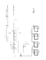
- FIG. 1 is a configuration diagram illustrating a liquefied gas treatment system for a vessel according to a first embodiment of the present invention.
- the liquefied gas treatment system of the present embodiment may be applied to an LNG carrier equipped with an MEGI engine as a main propulsion engine (that is, propulsion means using LNG as fuel).
- the liquefied gas treatment system 100 includes a fuel supply line 110 and a BOG line 140.
- the fuel supply line 110 is configured to provide a passage for transferring LNG from a cargo tank 1 to a main engine 3 as a propulsion system.
- the BOG line 140 is configured to provide a passage for transferring BOG generated from the cargo tank 1 to the main engine 3.
- the liquefied gas treatment system 100 using BOG supplies LNG to the main engine 3 as fuel through the fuel supply line 110 by an LNG pump 120 and an LNG vaporizer 130, supplies BOG to the main engine 3 as fuel through the BOG line 140 after compressing the BOG by a BOG compressor 150, and supplies surplus BOG from the BOG compressor 150 to an integrated inert gas generator/gas combustion unit (IGG/GCU) system 200.
- LNG to the main engine 3 as fuel through the fuel supply line 110 by an LNG pump 120 and an LNG vaporizer 130
- BOG to the main engine 3 as fuel through the BOG line 140 after compressing the BOG by a BOG compressor 150
- surplus BOG from the BOG compressor 150 to an integrated inert gas generator/gas combustion unit (IGG/GCU) system 200.
- ISG/GCU integrated inert gas generator/gas combustion unit
- An MEGI engine usable as the main engine 3 needs to be supplied with fuel at a high pressure of about 150 to 400 bara (absolute pressure). Therefore, as the LNG pump 120 and the BOG compressor 150 according to the present embodiment, a high pressure pump and a high pressure compressor are used which can compress LNG and BOG to a pressure necessary for the MEGI engine, respectively.
- the fuel supply line 110 provides a passage through which LNG supplied from the LNG cargo tank 1 by the driving of a transfer pump 2 is transferred to the main engine 3 as fuel, and the LNG pump 120 and the LNG vaporizer 130 are installed therein.
- the LNG pump 120 is installed in the fuel supply line 110 to provide a pumping force necessary for transferring the LNG.
- an LNG high pressure (HP) pump may be used.
- a plurality of LNG pumps 120 may be installed in parallel.
- the LNG vaporizer 130 is installed at a rear end of the LNG pump 120 in the fuel supply line 110 and vaporizes LNG transferred by the LNG pump 120.
- LNG is vaporized by heat exchange with a heat medium circulated and supplied through a heat medium circulation line 131.
- a variety of heating means including heaters, may be used for providing a vaporization heat of LNG.
- the LNG vaporizer 130 may use a high pressure (HP) vaporizer that can be used at a high pressure for vaporization of LNG.
- steam generated from a boiler or the like may be used as an example of the heat medium circulated and supplied through the heat medium circulation line 131.
- the BOG line 140 provides a passage for transferring BOG naturally generated from the cargo tank 1 to the main engine 3. Like the present embodiment, the BOG line 140 is connected to the fuel supply line 110 to supply BOG to the main engine 3 as fuel. Alternatively, the BOG line 140 may provide a passage for directly supplying BOG to the main engine 3.
- the BOG compressor 150 is installed on the BOG line 140 to compress BOG passing through the BOG line 140.
- the system may be configured such that two BOG compressors of the same specification are connected in parallel so as to satisfy redundancy requirements just like the general fuel supply systems.
- a single BOG compressor 150 is installed in a branched portion of a surplus BOG line 160 in the BOG line 140, it is possible to obtain additional effects of reducing burdens on costs for installation of the expensive BOG compressor 150 and burdens on maintenance.
- the surplus BOG line 160 provides a passage for supplying surplus BOG from the BOG compressor 150 to an integrated IGG/GCU system 200.
- the surplus BOG line 160 can supply surplus BOG as fuel to an auxiliary engine, such as a DF engine, as well as the integrated IGG/GCU system 200.
- the integrated IGG/GCU system 200 is a system in which an IGG and a GCU are integrated.
- a heater 180 may be installed in the connection line 170 so as to heat BOG or vaporized LNG passing therethrough, and a pressure reduction valve (PRV) 190 may be installed to reduce excessive pressure by adjusting a pressure caused by BOG or vaporized LNG.
- the heater 180 may be a gas heater using combustion heat of gas.
- the heater 180 may use a variety of heating means, including a heat medium circulation/supply unit providing a heat source for heating by the circulation of the heat medium.
- BOG When a pressure inside the cargo tank 1 is equal to or higher than a set pressure or a large amount of BOG is generated, BOG is compressed by the driving of the BOG compressor 150 and is then supplied as fuel to the main engine 3. In addition, when the pressure inside the cargo tank 1 is lower than the set pressure or a small amount of BOG is generated, LNG is transferred and vaporized by the driving of the LNG pump 120 and the LNG vaporizer 130 and is then supplied as fuel to the main engine 3.
- surplus BOG from the BOG compressor 150 is supplied to the integrated IGG/GCU system 200 or the auxiliary engine such as the DF engine through the surplus BOG line 160.
- the surplus BOG is consumed or is used for generating inert gas for supply to the cargo tank 1.
- the surplus BOG may be used as the fuel of the auxiliary engine or the like.
- the integrated IGG/GCU system 200 supplied with BOG may consume BOG continuously generated from the cargo tank 1 by BOG combustion inside a main body 210 and may, if necessary, generate combustion gas as inert gas for supply to the cargo tank 1.
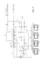
- FIG. 2 is a schematic configuration diagram illustrating a liquefied gas treatment system for a vessel according to a second embodiment of the present invention.
- FIG. 2 illustrates an example in which the liquefied gas treatment system of the present invention is applied to an LNG carrier equipped with a high pressure natural gas injection engine capable of using natural gas as fuel (that is, propulsion means using LNG as fuel), the liquefied gas treatment system of the present invention can also be applied to any type of vessels (LNG carrier, LNG RV, and the like) and marine plants (LNG FPSO, LNG FSRU, BMPP, and the like), in which a liquefied gas cargo tank is installed.
- vessels LNG carrier, LNG RV, and the like
- LNG FPSO LNG FPSO
- LNG FSRU LNG FSRU
- BMPP BMPP
- NBOG generated and discharged from a cargo tank 11 storing liquefied gas is transferred along a BOG supply line L1, is compressed in a compressor 13, and is then supplied to the high pressure natural gas injection engine, for example, an MEGI engine.
- the BOG is compressed at a high pressure of about 150 to 400 bara by the compressor 13 and is then supplied as fuel to the high pressure natural gas injection engine, for example, the MEGI engine.
- the cargo tank 11 has sealing and heat-insulating walls so as to store liquefied gas such as LNG in a cryogenic state, but cannot perfectly block heat transferred from the outside. Therefore, the liquefied gas is continuously vaporized within the cargo tank 11. In order to maintain the pressure of the BOG at an appropriate level, BOG is discharged from the cargo tank 11 through the BOG discharge line.
- liquefied gas such as LNG in a cryogenic state
- a discharge pump 12 is installed within the cargo tank 11 so as to discharge LNG to the outside of the cargo tank when necessary.
- the compressor 13 may include one or more compression cylinders 14 and one or more intercoolers 15 for cooling BOG of which the temperature is raised.
- the compressor 13 may be configured to compress BOG to, for example, about 400 bara.
- FIG. 2 illustrates the multi-stage compressor 13 including five compression cylinders 14 and five intercoolers 15, the number of the compression cylinders and the number of the intercoolers may be changed when necessary.
- a plurality of compression cylinders may be arranged within a single compressor, and a plurality of compressors may be connected in series.
- BOG compressed in the compressor 13 is supplied to the high pressure natural gas injection engine through the BOG supply line L1. All or part of the compressed BOG may be supplied to the high pressure natural gas injection engine according to an amount of fuel necessary for the high pressure natural gas injection engine.
- the first stream of the BOG when BOG discharged from the cargo tank 11 and compressed in the compressor 13 (that is, all BOG discharged from the cargo tank) is a first stream, the first stream of the BOG may be divided into a second stream and a third stream after compression.
- the second stream may be supplied as fuel to the high pressure natural gas injection engine, and the third stream may be liquefied and returned to the cargo tank.
- the second stream is supplied to the high pressure natural gas injection engine through the BOG supply line L1.
- the second stream may be supplied as fuel through a line (that is, the BOG supply line L1) connected to the high pressure natural gas injection engine after passing through all of the plurality of compression cylinders 14 included in the compressor 13, or may be supplied as fuel through a line (that is, the BOG branch line L8) connected to the DF engine after passing through a part of the plurality of compression cylinders 14 included in the compressor 13.
- the third stream is returned to the cargo tank 11 through the BOG return line L3.
- a heat exchanger 21 is installed in the BOG return line L3 so as to cool and liquefy the third stream.
- the third stream of the compressed BOG exchanges heat with the first stream of the BOG discharged from the cargo tank 11 and then supplied to the compressor 13.
- the third stream of the compressed BOG may be liquefied by receiving cold energy from the first stream of the BOG before compression.
- the BOG of the high pressure state is cooled and liquefied by heat exchange between the BOG of the cryogenic temperature immediately after being discharged from the cargo tank 11 and the BOG of the high pressure state compressed in the compressor 13.
- the LBOG cooled in the heat exchanger 21 and liquefied at least partially is decompressed while passing through an expansion valve 22 serving as decompressing means, and is supplied to a gas-liquid separator 23 in a gas-liquid mixed state.
- the LBOG may be decompressed to approximately atmospheric pressure (for example, decompressed from 300 bar to 3 bar) while passing through the expansion valve 22.
- the liquefied BOG is separated into gas and liquid components in the gas-liquid separator 23.
- the liquid component, that is, LNG is transferred to the cargo tank 11 through the BOG return line L3, and the gas component, that is, BOG, is discharged from the cargo tank 11 through a BOG recirculation line L5 and is joined with BOG supplied to the compressor 13. More specifically, the BOG recirculation line L5 extends from an upper end of the gas-liquid separator 23 and is connected to a more upstream side than the heat exchanger 21 in the BOG supply line L1.
- the pressure of the BOG after being decompressed by the decompressing means is set to be higher than the inside pressure of the cargo tank 11.
- the heat exchanger 21 is installed in the BOG return line L3, but the heat exchanger 21 may be installed in the BOG supply line L1 because the heat exchange is actually performed between the first stream of the BOG transferred through the BOG supply line L1 and the third stream of the BOG transferred through the BOG return line L3.
- Another expansion valve 24 may be further installed in the BOG recirculation line L5. Therefore, the gas component discharged from the gas-liquid separator 23 may be decompressed while passing through the expansion valve 24.
- a cooler 25 is installed in the BOG recirculation line L5 so as to further cool the third stream by heat exchange between the third stream of the BOG liquefied in the heat exchanger 21 and supplied to the gas-liquid separator 23 and the gas component separated from the gas-liquid separator 23 and transferred through the BOG recirculation line L5. That is, the cooler 25 additionally cools the BOG of a high pressure liquid state to natural gas of a low pressure cryogenic gas state.
- the cooler 25 is installed in the BOG recirculation line L5, but the cooler 25 may be installed in the BOG return line L3 because the heat exchange is actually performed between the third stream of the BOG transferred through the BOG return line L3 and the gas component transferred through the BOG recirculation line L5.
- the system may be configured such that the cooler 25 is omitted. If the cooler 25 is not installed, the total efficiency of the system may be slightly lowered. However, the pipe arrangement and the system operation may be facilitated, and the initial installation cost and the maintenance fee may be reduced.
- BOG having been compressed or being compressed stepwise in the compressor 13 is branched through the BOG branch lines L7 and L8 and is then used in BOG consuming means.
- the BOG consuming means may include a GCU, a DF generator (DFDG), and a gas turbine, each of which can use natural gas having a relatively lower pressure than the MEGI engine as fuel.
- the pressure of the BOG branched through the BOG branch lines L7 and L8 may be about 6 to 10 bara.
- BOG generated during the transportation of cargo (that is, LNG) in the LNG carrier may be used as the fuel of the engine, or may be reliquefied, be returned to the cargo tank and be stored therein. Therefore, an amount of BOG consumed in the GCU or the like can be reduced or removed. Furthermore, BOG can be treated by reliquefaction, without installing reliquefaction apparatuses using separate refrigerants such as nitrogen.
- FIG. 2 illustrates the example in which the BOG return line L3 for supplying the compressed BOG to the heat exchanger 21 is branched at the rear end of the compressor 13, the BOG return line L3 may be installed to branch the BOG being compressed stepwise in the compressor 13, like the above-described BOG branch lines L7 and L8.
- FIG. 3 illustrates a modification in which 2-stage compressed BOG is branched by two cylinders
- FIG. 4 illustrates a modification in which 3-stage compressed BOG is branched by three cylinders.
- the pressure of the BOG branched from the middle stage of the compressor 13 may be about 6 to 10 bara.
- BOG needs to be transferred while passing through an oil filter when BOG is branched at the rear stage or 4-stage or more of the compressor.
- the oil filter need not be used when BOG is branched at 3-stage or less of the compressor.
- FIG. 5 is a schematic configuration diagram illustrating a liquefied gas treatment system for a vessel according to a third embodiment of the present invention.
- the liquefied gas treatment system according to the third embodiment differs from the liquefied gas treatment system according to the second embodiment in that LNG can be used after forcible vaporization when an amount of BOG necessary for the MEGI engine or the DF generator is larger than an amount of BOG generated naturally in the cargo tank 11.
- LNG can be used after forcible vaporization when an amount of BOG necessary for the MEGI engine or the DF generator is larger than an amount of BOG generated naturally in the cargo tank 11.
- the liquefied gas treatment system for the vessel according to the third embodiment of the present invention is identical to that according to the second embodiment in that NBOG generated and discharged from a cargo tank 11 storing liquefied gas is transferred along a BOG supply line L1, is compressed in a compressor 13, and is then supplied to the high pressure natural gas injection engine, for example, an MEGI engine, or NBOG is supplied to a DF engine (DF generator) while being multi-stage compressed in the compressor 13 and is then used as fuel therein.
- the high pressure natural gas injection engine for example, an MEGI engine
- NBOG is supplied to a DF engine (DF generator) while being multi-stage compressed in the compressor 13 and is then used as fuel therein.
- the liquefied gas treatment system according to the third embodiment includes a forcible vaporization line L11 such that LNG stored in the cargo tank 11 can be vaporized in a forcible vaporizer 31 and be then supplied to the compressor 13 when an amount of BOG required as fuel in the high pressure natural gas injection engine or the DF engine is larger than an amount of BOG generated naturally in the cargo tank 11.
- fuel can be stably supplied even when a small amount of BOG is generated because a small amount of LNG is stored in the cargo tank 11, or an amount of BOG required as fuel in various engines is larger than an amount of BOG generated naturally in the cargo tank 11.
- FIG. 6 is a schematic configuration diagram illustrating a liquefied gas treatment system for a vessel according to a fourth embodiment of the present invention.
- the liquefied gas treatment system according to the fourth embodiment differs from the liquefied gas treatment system according to the second embodiment in that an expander 52 instead of the expansion valve is used as the decompressing means. That is, according to the fourth embodiment, LBOG cooled in a heat exchanger 21 and liquefied at least partially is decompressed while passing through the expander 52 and is supplied to a gas-liquid separator 23 in a gas-liquid mixed state.
- LBOG cooled in a heat exchanger 21 and liquefied at least partially is decompressed while passing through the expander 52 and is supplied to a gas-liquid separator 23 in a gas-liquid mixed state.
- the expander 52 produces energy while expanding the high pressure liquefied BOG at a low pressure.
- the LBOG may be decompressed to approximately atmospheric pressure while passing through the expander 52.
- the liquefied BOG is separated into gas and liquid components in the gas-liquid separator 23.
- the liquid component, that is, LNG is transferred to the cargo tank 11 through a BOG return line L3
- the gas component, that is, BOG is discharged from the cargo tank 11 through a BOG recirculation line L5 and is joined with BOG supplied to the compressor 13.
- the BOG recirculation line L5 extends from an upper end of the gas-liquid separator 23 and is connected to a more upstream side than the heat exchanger 21 in the BOG supply line L1.
- Another decompressing means for example, an expansion valve 24, may be further installed in the BOG recirculation line L5. Therefore, the gas component discharged from the gas-liquid separator 23 may be decompressed while passing through the expansion valve 24.
- FIGS. 7 and 8 are schematic configuration diagrams illustrating liquefied gas treatment systems for a vessel according to modifications of the fourth embodiment of the present invention.
- the BOG return line L3 for supplying the compressed BOG to the heat exchanger 21 is branched at the rear end of the compressor 13.
- the BOG return line L3 may be installed to branch BOG being compressed stepwise in the compressor 13.
- FIG. 7 illustrates a modification in which 2-stage compressed BOG is branched by two cylinders
- FIG. 8 illustrates a modification in which 3-stage compressed BOG is branched by three cylinders.
- BOG needs to be transferred while passing through an oil filter when BOG is branched at the rear stage or 4-stage or more of the compressor.
- the oil filter need not be used when BOG is branched at 3-stage or less of the compressor.
- the liquefied gas treatment system according to the fourth embodiment may be modified such that the cooler 25 (see FIG. 6 ) serving as the heat exchanger for additionally cooling the BOG cooled and liquefied while passing through the heat exchanger 21 is omitted. If the cooler 25 is not installed, the total efficiency of the system may be slightly lowered. However, the pipe arrangement and the system operation may be facilitated, and the initial installation cost and the maintenance fee may be reduced.
- the liquefied gas treatment system according to the fourth embodiment may be modified such that the expander 52 and the expansion valve 55 serving as the decompressing means are arranged in parallel.
- the expander 52 and the expansion valve 55 arranged in parallel are disposed between the heat exchanger 21 and the gas-liquid separator 23.
- a bypass line L31 which is branched from the BOG return line L3 between the heat exchanger 21 and the gas-liquid separator 23 and is configured to bypass the expander 52, is installed so as to install the expansion valve 55 in parallel and use only the expander 52 or the expansion valve 55 when necessary.
- the expansion valve 55 is closed when the liquefied BOG is expanded by using only the expander 52, and on-off valves 53 and 54 installed respectively at the front end and the rear end of the expander 52 are closed when the liquefied BOG is expanded by using only the expansion valve 55.
- BOG generated during the transportation of cargo (that is, LNG) in the LNG carrier may be used as the fuel of the engine, or may be reliquefied, be returned to the cargo tank and be stored therein. Therefore, an amount of BOG consumed in the GCU or the like can be reduced or removed. Furthermore, BOG can be treated by reliquefaction, without installing reliquefaction apparatuses using separate refrigerants such as nitrogen.
- BOG generated from the cargo tank storing the LNG may be used as the fuel of the engine (including engines for power generation as well as engines for propulsion) or may be reliquefied, thereby reducing or removing the unnecessary waste of BOG.
- FIG. 9 is a schematic configuration diagram illustrating a liquefied gas treatment system for a vessel according to a fifth embodiment of the present invention.
- the liquefied gas treatment system according to the fifth embodiment differs from the liquefied gas treatment system according to the second embodiment in that BOG liquefied in the heat exchanger 21 and then decompressed in the decompressing means (for example, the expansion valve 22) is returned to the cargo tank 11, without passing through the gas-liquid separator 23.
- the decompressing means for example, the expansion valve 22
- the BOG (that is, two-phase BOG), which becomes a state in which the gas component (that is, flash gas) and the liquid component (that is, liquefied BOG) are mixed while being decompressed after liquefaction, is returned to the cargo tank 11 through the BOG return line L3.
- the BOG return line L3 may be configured such that the two-phase BOG returned to the cargo tank 11 is injected to the bottom of the cargo tank 11.
- the gas component (that is, flash gas) of the two-phase BOG injected to the bottom of the cargo tank 11 may be partially melted into LNG stored in the cargo tank 11, or may be liquefied by cold energy of LNG.
- flash gas (BOG) which is not melted or liquefied, is discharged from the cargo tank 11 again through the BOG supply line L1 together with BOG (NBOG) additionally generated in the cargo tank 11.
- BOG BOG
- the flash gas discharged from the cargo tank 11 together with the newly generated BOG is recirculated to the compressor 13 along the BOG supply line L1.
- the two-phase BOG after expansion is injected to the bottom of the cargo tank 11, a larger amount of BOG is liquefied by the LNG stored in the cargo tank 11. Furthermore, since the facilities such as the gas-liquid separator or the like are omitted, installation cost and operation cost can be saved.
- FIG. 10 is a schematic configuration diagram illustrating a liquefied gas treatment system for a vessel according to a first modification of the fifth embodiment of the present invention.
- the first modification of the fifth embodiment illustrated in FIG. 10 differs from the liquefied gas treatment system illustrated in FIG. 9 according to the fifth embodiment in that an expander 52 instead of the expansion valve is used as the decompressing means. That is, according to the first modification of the fifth embodiment, LBOG cooled and liquefied in a heat exchanger 21 is decompressed to a gas-liquid mixed state while passing through the expander 52 and is returned to a cargo tank 11 in a two-phase state.
- FIG. 11 is a schematic configuration diagram illustrating a liquefied gas treatment system for a vessel according to a second modification of the fifth embodiment of the present invention.
- the second modification of the fifth embodiment illustrated in FIG. 11 differs from the liquefied gas treatment system illustrated in FIG. 9 according to the fifth embodiment in that a plurality of compressors (for example, a first compressor 13a and a second compressor 13b) instead of the multi-stage compressor is used as the compressing means.
- a plurality of compressors for example, a first compressor 13a and a second compressor 13b
- NBOG generated and discharged from a cargo tank 11 storing liquefied gas is transferred along a BOG supply line L1 and is then supplied to the first compressor 13a.
- the BOG compressed in the first compressor 13a may be compressed at about 6 to 10 bara and then supplied to a demander, that is, a propulsion system (for example, DFDE) using LNG as fuel, along a fuel supply line L2.
- the BOG remaining after being supplied to the DFDE may be additionally compressed by the second compressor 13b serving as a booster compressor.
- the BOG may be liquefied while moving along a BOG return line L3 and be then returned to the cargo tank 11.
- the first compressor 13a may be a 1-stage compressor including one compression cylinder 14a and one intercooler 15a.
- the second compressor 13b may be a 1-stage compressor including one compression cylinder 14b and one intercooler 15b. If necessary, the second compressor 13b may be provided with a multi-stage compressor including a plurality of compression cylinders and a plurality of intercoolers.
- the BOG compressed in the first compressor 13a is compressed at about 6 to 10 bara and then supplied to the demander, for example, the DF engine (that is, DFDE), through the fuel supply line L2. At this time, all or part of the compressed BOG may be supplied to the engine according to an amount of fuel necessary for the engine.
- the first stream of the BOG may be divided into a second stream and a third stream at a downstream side of the first compressor 13a.
- the second stream may be supplied as fuel to the propulsion system, that is, the DF engine (DFDE), and the third stream may be liquefied and returned to the cargo tank 11.
- DFDE DF engine
- the second stream is supplied to the DFDE through the fuel supply line L2, and the third stream is further compressed in the second compressor 13b, experiences liquefaction and decompression processes, and is returned to the cargo tank 11 through the BOG return line L3.
- a heat exchanger 21 is installed in the BOG return line L3 so as to liquefy the third stream of the compressed BOG.
- the third stream of the BOG compressed in the heat exchanger 21 exchanges heat with the first stream of the BOG discharged from the cargo tank 11 and then supplied to the first compressor 13a.
- the third stream of the compressed BOG may be cooled (that is, liquefied at least partially) by receiving cold energy from the first stream of the BOG before compression.
- the BOG of the high pressure state is cooled (liquefied) by heat exchange between the BOG of the cryogenic temperature immediately after being discharged from the cargo tank 11 and the BOG of the high pressure state compressed in the compressor 13.
- the LBOG cooled in the heat exchanger 21 is decompressed while passing through an expansion valve 22 (for example, J-T valve) serving as decompression means, and is then supplied to the cargo tank 11 in a gas-liquid mixed state.
- the LBOG may be decompressed to approximately atmospheric pressure (for example, decompressed from 300 bar to 3 bar) while passing through the expansion valve 22.
- BOG compressed in the first compressor 13a is branched through the BOG branch line L7 and is then used in BOG consuming means.
- the BOG consuming means may include a GCU and a gas turbine, each of which can use natural gas as fuel.
- FIG. 12 is a schematic configuration diagram illustrating a liquefied gas treatment system for a vessel according to a third modification of the fifth embodiment of the present invention.
- the third modification of the fifth embodiment illustrated in FIG. 12 differs from the liquefied gas treatment system illustrated in FIG. 11 according to the second modification of the fifth embodiment in that an expander 52 instead of the expansion valve is used as the decompressing means. That is, according to the third modification of the fifth embodiment, LBOG cooled and liquefied in a heat exchanger 21 is decompressed to a gas-liquid mixed state while passing through the expander 52 serving as the decompressing means and is returned to a cargo tank 11 in a two-phase state.
- BOG generated during the transportation of cargo (that is, LNG) in the LNG carrier may be used as the fuel of the engine, or may be reliquefied, be returned to the cargo tank and be stored therein. Therefore, an amount of BOG consumed in the GCU or the like can be reduced or removed. Furthermore, BOG can be treated by reliquefaction, without installing reliquefaction apparatuses using separate refrigerants such as nitrogen.
- BOG generated from the cargo tank storing the LNG may be used as the fuel of the engine (including engines for power generation as well as engines for propulsion) or may be reliquefied, thereby reducing or removing the unnecessary waste of BOG.
- FIG. 13 is a configuration diagram illustrating a liquefied gas treatment system for a vessel according to a sixth embodiment of the present invention.
- the liquefied gas treatment system illustrated in FIG. 13 according to the sixth embodiment of the present invention is configured by integrating the liquefied gas treatment system illustrated in FIG. 1 according to the first embodiment (hybrid system including the line through which LNG is compressed by the high pressure pump 120 and supplied as fuel to the propulsion system, and the line through which BOG is compressed by the compressor 150 and supplied as fuel to the propulsion system) and the liquefied gas treatment system illustrated in FIG. 2 according to the second embodiment.
- the liquefied gas treatment systems illustrated in FIGS. 3 to 13 according to the third to fifth embodiments can also be integrated with the hybrid system (see L23, L24 and L25 of FIG. 13 ) as illustrated in FIG. 13 .
- the liquefied gas treatment system illustrated in FIG. 13 includes a high pressure natural gas injection engine (for example, MEGI engine) as a main engine, and a DF engine (DF generator: DFDG) as a sub engine.
- a high pressure natural gas injection engine for example, MEGI engine
- DF engine DF generator: DFDG
- the main engine is used for propulsion to navigate the vessel
- the sub engine is used for power generation to supply power to various apparatuses and facilities installed in the vessel.
- the present invention is not limited to the purposes of the main engine and the sub engine.
- a plurality of main engines and a plurality of sub engines may be installed.
- the liquefied gas treatment system according to the present invention is configured such that the natural gas stored in the cargo tank 11 (that is, the BOG of the gas state and the LNG of the liquid state) can be supplied as fuel to the engines (that is, the MEGI engine serving as the main engine and the DF engine serving as the sub engine).
- the natural gas stored in the cargo tank 11 that is, the BOG of the gas state and the LNG of the liquid state
- the engines that is, the MEGI engine serving as the main engine and the DF engine serving as the sub engine.
- the liquefied gas treatment system includes a main BOG supply line L1 serving as a BOG supply line to supply the main engine with BOG stored in the cargo tank 11, and a sub BOG supply line L8 branched from the main BOG supply line L1 to supply the sub engine with BOG.
- the main BOG supply line L1 has the same configuration as the BOG supply line L1 of the foregoing embodiment. However, in the description given with reference to FIG. 13 , this BOG supply line is referred to as the main BOG supply line L1 so as to distinguish from the BOG supply line for the DF engine (that is, the sub BOG supply line L8).
- the sub BOG supply line L8 has the same configuration as the BOG branch line L8 of the foregoing embodiment. However, in the description given with reference to FIG. 13 , this BOG supply line is referred to as the sub BOG supply line L8 so as to distinguish from the main BOG supply line L1.
- the liquefied gas treatment system includes a main LNG supply line L23 serving to supply the main engine with LNG stored in the cargo tank 11, and a sub LNG supply line L24 branched from the main LNG supply line L23 to supply the sub engine with LNG.
- a compressor 13 for compressing the BOG is installed in the main BOG supply line L1
- a high pressure pump 43 for compressing the LNG is installed in the main LNG supply line L23.
- the NBOG generated in the cargo tank 11 storing liquefied gas and discharged through the BOG discharge valve 41 is transferred along the main BOG supply line L1, is compressed in the compressor 13, and is then supplied to the high pressure natural gas injection engine, for example, the MEGI engine.
- the BOG is compressed at a high pressure of about 150 to 400 bara by the compressor 13 and is then supplied to the high pressure natural gas injection engine.
- the cargo tank 11 has sealing and heat-insulating walls so as to store liquefied gas such as LNG in a cryogenic state, but cannot perfectly block heat transferred from the outside. Therefore, the liquefied gas is continuously vaporized within the cargo tank 11, and BOG is discharged from the cargo tank 11 so as to maintain the pressure of the BOG at an appropriate level.
- liquefied gas such as LNG in a cryogenic state
- the compressor 13 may include one or more compression cylinders 14 and one or more intercoolers 15 for cooling BOG of which the temperature is raised.
- the compressor 13 may be configured to compress BOG to, for example, about 400 bara.
- FIG. 13 illustrates the multi-stage compressor 13 including five compression cylinders 14 and five intercoolers 15, the number of the compression cylinders and the number of the intercoolers may be changed when necessary.
- a plurality of compression cylinders may be arranged within a single compressor, and a plurality of compressors may be connected in series.
- the BOG compressed in the compressor 13 is supplied to the high pressure natural gas injection engine through the main BOG supply line L1. All or part of the compressed BOG may be supplied to the high pressure natural gas injection engine according to an amount of fuel necessary for the high pressure natural gas injection engine.
- the sub BOG supply line L8 for supply fuel gas to the sub engine is branched from the main BOG supply line L1. More specifically, the sub BOG supply line L8 is branched from the main BOG supply line L1 such that BOG can be branched in the process of being multi-stage compressed in the compressor 13.
- FIG. 13 illustrates that the 2-stage compressed BOG is branched and a part of the BOG is supplied to the sub engine through the sub BOG supply line L8, this is merely exemplary.
- the system can also be configured such that 1-stage compressed BOG or 3- to 5-stage compressed BOG is branched and then supplied to the sub engine through the sub BOG supply line.
- the compressor a compressor manufactured by Burckhardt company may be used.
- the compressor manufactured by Burckhardt company includes five cylinders. It is known that the three cylinders of the front stage are operated in an oil-free-lubricated method and two cylinders of the rear stage are operated in an oil-lubricated method. Therefore, in the case where the compressor manufactured by Burckhardt company is used as the compressor 13 for compressing BOG, the BOG needs to be transferred through an oil filter when the BOG is branched at 4-stage or more of the compressor. However, it is advantageous in that the oil filter need not be used when the BOG is branched at 3-stage or less of the compressor.
- the required pressure of the DF engine (for example, DFDG) serving as the sub engine is lower than that of the MEGI engine. Therefore, when the BOG compressed at a high pressure is branched at the rear end of the compressor 13, it is inefficient because the pressure of the BOG needs to be lowered again and then supplied to the sub engine.
- DFDG DFDG
- the liquefied gas treatment system of the present invention can reliquefy the BOG and return the reliquefied BOG to the cargo tank.
- BOG having been compressed or being compressed stepwise in the compressor 13 can be branched through the BOG branch line L7 and be used in the BOG consuming means.
- the BOG consuming means may include a GCU and a gas turbine, each of which can use natural gas having a relatively lower pressure than the MEGI engine as fuel.
- the BOG branch line L7 may be branched from the sub BOG supply line L8.
- FIG. 13 illustrates the example in which the BOG return line L3 for supplying the compressed BOG to the heat exchanger 21 is branched at the rear end of the compressor 13, the BOG return line L3 may be installed to branch the BOG being compressed stepwise in the compressor 13, like the above-described BOG branch line L7 and the sub BOG supply line L8 serving as the BOG branch line.
- FIG. 3 illustrates a modification in which 2-stage compressed BOG is branched by two cylinders
- FIG. 4 illustrates a modification in which 3-stage compressed BOG is branched by three cylinders.
- the pressure of the BOG branched from the middle stage of the compressor 13 may be about 6 to 10 bara.
- BOG needs to be transferred while passing through an oil filter when BOG is branched at the rear stage or 4-stage or more of the compressor.
- the oil filter need not be used when BOG is branched at 3-stage or less of the compressor.
- a discharge pump 12 and a high pressure pump 43 are installed in the main LNG supply line L23.
- the discharge pump 12 is installed inside the cargo tank 11 and configured to discharge LNG to the outside of the cargo tank 11.
- the high pressure pump 43 is configured to secondarily compress LNG, which is primarily compressed in the discharge pump 12, to a pressure necessary for the MEGI engine.
- the discharge pump 12 may be installed in each cargo tank 11. Although only one high pressure pump 43 is illustrated in FIG. 4 , a plurality of high pumps may be connected in parallel when necessary.
- the pressure of the fuel gas necessary for the MEGI engine is a high pressure of about 150 to 400 bara (absolute pressure).
- high pressure refers to a pressure necessary for the MEGI engine, for example, a pressure of about 150 to 400 bara (absolute pressure).
- the LNG discharged from the cargo tank 11 storing liquefied gas through the discharge pump 12 is transferred along the main LNG supply line L23 and is then supplied to the high pressure pump 43. Then, the LNG is compressed to a high pressure in the high pressure pump 43, is supplied to the vaporizer 44, and is vaporized in the vaporizer 44.
- the vaporized LNG is supplied as fuel to the high pressure natural gas injection engine, that is, the MEGI engine. Since the pressure necessary for the MEGI engine is in a supercritical state, the LNG compressed to the high pressure is a state that is neither gas nor liquid. Therefore, it should be considered that the expression "vaporizing the LNG compressed to the high pressure in the vaporizer 44" means raising the temperature of the LNG being in the supercritical state up to a temperature necessary for the MEGI engine.
- the sub LNG supply line L24 for supply fuel gas to the sub engine is branched from the main LNG supply line L23. More specifically, the sub LNG supply line L24 is branched from the main LNG supply line L23 such that LNG can be branched before being compressed in the high pressure pump 43.
- the sub LNG supply line L24 is illustrated as being branched from the main LNG supply line L23 at the upstream side of the high pressure pump 43.
- the sub LNG supply line L24 may be branched from the main LNG supply line L23 at the downstream side of the high pressure pump 43.
- the LNG supply line L24 since the pressure of the LNG has been raised by the high pressure pump 43, it is necessary to lower the pressure of the LNG to the pressure necessary for the sub engine by the decompressing means before supplying the LNG to the sub engine as fuel.
- additional decompressing means need not be installed when the sub LNG supply line L24 is branched at the upstream side of the high pressure pump 43.
- a vaporizer 45, a gas-liquid separator 46, and a heater 47 are installed in the sub LNG supply line L24 so as to adjust the methane number and temperature of LNG supplied as fuel to the value required in the DF engine.
- the methane number of the LNG is lower than the methane number required in the DF engine.
- Ratios of hydrocarbon components (methane, ethane, propane, butane, and the like) constituting the LNG are different according to producing areas. Therefore, it is not suitable to vaporize the LNG as it is and then supply the vaporized LNG to the DF engine as fuel.
- the LNG is heated and partially vaporized in the vaporizer 45
- the fuel gas partially vaporized to a state in which the gas state (that is, natural gas) and the liquid state (that is, LNG) are mixed is supplied to the gas-liquid separator 46 and is separated into gas and liquid. Since the vaporization temperature of heavy hydrocarbon (HHC) component having a high calorific value is relatively high, a ratio of the HHC component is relatively increased in the LNG of the liquid state that remains without being vaporized in the partially vaporized BOG. Therefore, the methane number of the fuel gas can be increased by separating the liquid component in the gas-liquid separator 46, that is, by separating the HHC component.
- HHC heavy hydrocarbon
- the heating temperature in the vaporizer 45 can be adjusted considering the ratio of the hydrocarbon component included in the LNG, the methane number required in the engine, and the like.
- the heating temperature in the vaporizer 45 may be determined in the range of -80°C to-120°C.
- the liquid component separated from the fuel gas in the gas-liquid separator 46 is returned to the cargo tank 11 through the liquid-component return line L5.
- the BOG return line L3 and the liquid-component return line L5 may extend to the cargo tank 11 after joining each other.
- the fuel gas, the methane number of which is adjusted, is supplied to the heater 47 through the sub LNG supply line L24, is further heated to a temperature required in the sub engine, and is then supplied as fuel to the sub engine.
- the required methane number is generally 80 or more.
- the methane number before separating the HHC component is 71.3, and a lower heating value (LHV) at that time is 48, 872.8 kJ/kg (at 1 atm, saturated vapor).
- LHV lower heating value
- the fuel gas there are two passages through which the fuel gas is supplied to the engines (the main engine and the sub engine). That is, the fuel gas may be supplied to the engines after being compressed through the compressor 13, or may be supplied to the engines after being compressed through the high pressure pump 43.
- a vessel such as LNG carrier or LNG RV, is used to transport LNG from a producing area to a consumer. Therefore, when sailing to the producing area, the vessel sails in a laden condition in which the LNG is fully loaded into the cargo tank. When returning to the producing area after unloading the LNG, the vessel sails in a ballast condition in which the cargo tank is almost empty. In the laden condition, a large amount of BOG is generated because an amount of LNG is relatively large. In the ballast condition, a relatively small amount of BOG is generated because an amount of LNG is small.
- an amount of BOG generated when the capacity of the LNG cargo tank is about 130,000 to 350,000 is 3 to 4 ton/h in the laden condition and is 0.3 to 0.4 ton/h in the ballast condition.
- an amount of fuel gas necessary for the engines is about 1 to 4 ton/h (about 1.5 ton/h on average) in the case of the MEGI engine and is about 0.5 ton/h in the case of the DF engine (DFDG).
- BOR boil-off rate
- the fuel gas is supplied to the engines through the compressor line in the laden condition in which a large amount of BOG is generated, and the fuel gas is supplied to the engines through the high pressure pump lines in the ballast condition in which a small amount of BOG is generated.
- LNG may be forcibly vaporized and supplied as much as a deficient amount while supplying BOG as fuel to the MEGI engine through the compressor.
- BOG since a generation amount of BOG is small in the ballast condition, BOG is not discharged but accumulated until the cargo tank reaches a predetermined pressure, and is intermittently discharged and supplied as fuel to the DF engine or the MEGI engine, instead of discharging and consuming BOG whenever the BOG is generated.
- the engine of the vessel may be simultaneously supplied with BOG compressed by the compressor 13 and LNG compressed by the high pressure pump 43 as fuel.
- the engine of the vessel (the DF engine or the MEGI engine) may be alternately supplied with BOG compressed by the compressor 13 and LNG compressed by the high pressure pump 43 as fuel.
- a fuel supply system which uses BOG generated in the storage tank as fuel in a normal condition, and forcibly vaporizes LNG and uses the vaporized LNG as fuel together with the BOG when an amount of BOG is smaller than a necessary amount of fuel.
- BOG generated in the storage tank
- LNG used as fuel together with the BOG when an amount of BOG is smaller than a necessary amount of fuel.
- Such a fuel supply system is limited to a case where only a low-pressure engine is installed in a vessel.
- the naturally generated BOG and the forcibly vaporized LNG are different in the heating value and the methane number.
- the above-described embodiments of the present invention significantly differ from the fuel supply system mounted with only the low-pressure engine, in that both of the high-pressure engine supplied with the fuel at a high pressure (for example, MEGI engine, about 150 to 400 bara) and the low-pressure engine supplied with the fuel at a low pressure (for example, DF engine, about 6-10 bara) are mounted.
- a high pressure for example, MEGI engine, about 150 to 400 bara
- DF engine low-pressure engine supplied with the fuel at a low pressure
- the BOG when the generation amount of BOG is smaller than the amount of fuel required in the entire engine, the BOG is supplied as the fuel to only the low-pressure engine, or the LNG is supplied as the fuel to both the high-pressure engine and the low-pressure engine.
- the BOG and the LNG are alternately supplied as the fuel to the engines. Therefore, it is possible to solve the problem occurring when the BOG and the forcibly vaporized LNG are supplied to one engine in a mixed manner.
- the BOG compressed by the compressor 13 and the LNG compressed by the high pressure pump 43 can be simultaneously supplied as the fuel to one engine as necessary.
- redundancy important facilities are required to be installed by two in consideration of emergency (redundancy). That is, the redundancy of important facilities is required such that extra facilities capable of performing the same function as the main facility, and the extra equipment is set to a standby state during the normal operation of the main facility and takes over the function of the main facility when the main facility does not operate due to malfunction.
- the facilities requiring the redundancy may include rotating facilities, for example, compressors or pumps.
- BOG generated during the transportation of cargo (that is, LNG) in the LNG carrier may be used as the fuel of the engine, or may be reliquefied, be returned to the cargo tank and be stored therein. Therefore, an amount of BOG consumed in the GCU or the like can be reduced or removed. Furthermore, BOG can be treated by reliquefaction, without installing reliquefaction apparatuses using separate refrigerants such as nitrogen.
- the BOG remaining after being used as the fuel of the engine can be reliquefied and returned to the cargo tank, thereby preventing the waste of BOG.
Abstract
Description
- The present invention relates to a liquefied gas treatment method for a vessel.
- Recently, the consumption of liquefied gas, such as liquefied natural gas (LNG) or liquefied petroleum gas (LPG), has been rapidly increasing throughout the world. Liquefied gas is transported in a gas state through onshore or offshore gas pipelines, or is transported to a remote consumption place while being stored in a liquefied state inside a liquefied gas carrier. Liquefied gas, such as LNG or LPG, is obtained by cooling natural gas or petroleum gas to a cryogenic temperature (in the case of LNG, about-163°C). Since the volume of liquefied gas is considerably reduced as compared to a gas state, liquefied gas is very suitable for a long-distance marine transportation.
- A liquefied gas carrier such as an LNG carrier is designed to load liquefied gas, sail across the sea, and unload the liquefied gas at an onshore consumption place. To this end, the liquefied gas carrier includes a storage tank (also called "cargo tank") that can withstand a cryogenic temperature of liquefied gas.
- Examples of a marine structure provided with a cargo tank capable of storing cryogenic liquefied gas may include vessels such as a liquefied gas carrier and an LNG Regasification Vessel (LNG RV), or structures such as an LNG Floating Storage and Regasification Unit (LNG FSRU) and an LNG Floating, Production, Storage and Off-loading (LNG FPSO), and a Barge Mounted Power Plant (BMPP).
- The LNG RV is a self-propelled, floatable liquefied gas carrier equipped with an LNG regasification facility, and the LNG FSRU is a marine structure that stores LNG unloaded from an LNG carrier on the sea far away from the land and, if necessary, supplies the LNG to an onshore consumption place by gasifying the LNG. The LNG FPSO is a marine structure that refines extracted LNG on the sea, stores the LNG in a storage tank after direct liquefaction, and, if necessary, transships the LNG to an LNG carrier. The BMPP is a structure that is equipped with a power generation facility to produce electricity on the sea.
- The term "vessel" as used herein is a concept including a liquefied gas carrier such as an LNG carrier, an LNG RV, and structures such as an LNG FPSO, an LNG FSRU, and a BMPP.
- Since the liquefaction temperature of natural gas is a cryogenic temperature of-163°C at ambient pressure, LNG is likely to be vaporized even when the temperature of LNG is slightly higher than -163 °C at ambient pressure. In the case of a conventional LNG carrier, even though an LNG cargo tank is thermally insulated, external heat is continuously transferred to LNG. Therefore, during the transportation of LNG by the LNG carrier, LNG is continuously vaporized within the LNG cargo tank and boil-off gas (hereinafter, referred to as BOG) is generated within the LNG cargo tank.
- The generated natural gas may increase the inside pressure of the cargo tank and accelerate the flow of the natural gas due to the rocking of the vessel, causing structural problems. Therefore, it is necessary to suppress the generation of BOG.
- Conventionally, in order to suppress the generation of BOG within the cargo tank of the liquefied gas carrier, a method of discharging the BOG from the cargo tank and burning the BOG, a method of discharging the BOG from the cargo tank, reliquefying the BOG through a reliquefaction apparatus, and returning the BOG to the cargo tank, a method of using the BOG as fuel for a vessel's propulsion engine, and a method of suppressing the generation of BOG by maintaining an inside pressure of a cargo tank at a high level have been used solely or in combination.
- In the case of a conventional vessel equipped with a BOG reliquefaction apparatus, BOG inside a cargo tank is discharged from the cargo tank and then reliquefied through a reliquefaction apparatus in order to maintain a pressure of the cargo tank at an appropriate level. In this case, the discharged BOG is reliquefied through heat exchange with a refrigerant (for example, nitrogen, mixed refrigerant, or the like) cooled to a cryogenic temperature in the reliquefaction apparatus including a refrigeration cycle, and the reliquefied BOG is returned to the cargo tank.
- In the case of a conventional LNG carrier equipped with a DFDE propulsion system, BOG is consumed in such a manner that it is supplied as fuel to the DFDE after treating BOG by only a BOG compressor and heating, without installing the reliquefaction facility. Therefore, when an amount of fuel necessary for an engine is smaller than a generation amount of BOG, there is a problem that BOG is burnt in a gas combustion unit (GCU) or is vented to atmosphere.
- Even though a conventional LNG carrier equipped with a reliquefaction facility and a low-speed diesel engine can treat BOG through the reliquefaction facility, the control of the entire system is complicated due to the operation complexity of the reliquefaction facility using nitrogen gas, and a considerable amount of power is consumed.
- Consequently, there is a need for continuous research and development of systems and methods for efficiently treating liquefied gas, including BOG generated naturally from the cargo tank.
- The present invention has been made in an effort to solve the above problems and is directed to a liquefied gas treatment system and method for a vessel, which includes a cargo tank storing LNG, and an engine supplied with the LNG stored in the cargo tank and using the LNG as fuel, wherein the BOG generated in the cargo tank and the LNG stored in the cargo tank are used in the engine as fuel, thereby achieving the efficient use of liquefied gas.
- According to an aspect of the present invention, there is provided a liquefied gas treatment method for a vessel, which is performed by a liquefied gas treatment system for the vessel including a cargo tank storing liquefied natural gas (LNG), and a main engine and a sub engine using the LNG stored in the cargo tank as fuel, the liquefied gas treatment method system including a compressor line configured to compress BOG generated in the cargo tank by a compressor and supply the compressed BOG to the main engine and the sub engine as fuel, and a pump line configured to compress the LNG stored in the cargo tank by a pump and supply the compressed LNG to the main engine and the sub engine as fuel, the liquefied gas treatment method including: supplying the BOG generated in the cargo tank to at least one of the main engine and the sub engine as fuel through the compressor line in a laden condition in which an amount of the LNG stored in the cargo tank is larger than in a ballast condition.
- In the ballast condition, the LNG stored in the cargo tank may be supplied as fuel to the main engine and the sub engine through the pump line.
- In the ballast condition, the BOG generated in the cargo tank may be supplied as fuel to one of the main engine and the sub engine through the compressor line.
- In the ballast condition, the BOG generated in the cargo tank may be supplied as fuel to the sub engine through the compressor line, and the LNG stored in the cargo tank may be supplied as fuel to the main engine through the pump line.
- In the ballast condition, the BOG generated in the cargo tank may be intermittently supplied as fuel to at least one of the main engine and the sub engine through the compressor line, and when the BOG is not supplied to at least one of the main engine and the sub engine, the LNG stored in the cargo tank may be supplied as fuel to at least one of the main engine and the sub engine through the pump line.
- In the ballast condition, the BOG generated in the cargo tank and the LNG stored in the cargo tank may be simultaneously supplied as fuel to the main engine and the sub engine.
- The compressor may include a plurality of compression cylinders, and the BOG generated in the cargo tank may be compressed by a part of the plurality of compression cylinders and is supplied as fuel to the sub engine.
- The BOG generated in the cargo tank and forcibly vaporized LNG may be supplied to and compressed by the compressor and are supplied as fuel to at least one of the main engine and the sub engine.
- When the LNG stored in the cargo tank is supplied to the sub engine, a heavy hydrocarbon component may be separated from the LNG so as to adjust a methane number of the LNG to a value necessary for the sub engine.
- BOG, which is not supplied as fuel to the main engine and the sub engine among BOG compressed by the compressor, may be liquefied by exchanging heat with BOG that is discharged from the cargo tank and transferred to the compressor.
- According to the present invention, all BOG generated during the transportation of cargo (that is, LNG) in the LNG carrier can be used as the fuel of the engine, or may be reliquefied, be returned to the cargo tank and be stored therein. Therefore, an amount of BOG consumed in the GCU or the like can be reduced or removed. Furthermore, BOG can be treated by reliquefaction, without using separate refrigerants such as nitrogen.
- Therefore, according to the liquefied gas treatment system and method of the present invention, BOG generated from the cargo tank can be reliquefied without installing a reliquefaction apparatus consuming a large amount of energy and requiring excessive initial installation cost, thereby saving energy consumed in the reliquefaction apparatus.
- In addition, according to the liquefied gas treatment system and method of the present invention, a part of compressed BOG after pressurizing BOG discharged from a cargo tank can be supplied to a high pressure gas injection engine (that is, a propulsion system) as fuel. The remaining compressed BOG can be cooled with cold energy of BOG after discharge from the cargo and before compression, and returned to the cargo tank.
- In addition, in the liquefied gas treatment system and method according to the present invention, since it is unnecessary to install the reliquefaction apparatuses using separate refrigerants (that is, nitrogen-refrigerant refrigeration cycle, mixed-refrigerant refrigeration cycle, or the like), facilities for supplying and storing the refrigerants need not be separately installed. Consequently, it is possible to save initial installation cost and operation cost for configuring the entire system.
- In addition, according to the liquefied gas treatment system and method of the present invention, when BOG cooled and liquefied in the heat exchanger after compression is decompressed by the expander, wasted energy can be reused because energy can be generated during expansion
-
-
FIG. 1 is a schematic configuration diagram illustrating a liquefied gas treatment system for a vessel according to a first embodiment of the present invention. -
FIG. 2 is a schematic configuration diagram illustrating a liquefied gas treatment system for a vessel according to a second embodiment of the present invention. -
FIGS. 3 and4 are schematic configuration diagrams illustrating liquefied gas treatment systems for a vessel according to modifications of the second embodiment of the present invention. -
FIG. 5 is a schematic configuration diagram illustrating a liquefied gas treatment system for a vessel according to a third embodiment of the present invention. -
FIG. 6 is a schematic configuration diagram illustrating a liquefied gas treatment system for a vessel according to a fourth embodiment of the present invention. -
FIGS. 7 and8 are schematic configuration diagrams illustrating liquefied gas treatment systems for a vessel according to modifications of the fourth embodiment of the present invention. -
FIG. 9 is a schematic configuration diagram illustrating a liquefied gas treatment system for a vessel according to a fifth embodiment of the present invention. -
FIGS. 10 to 12 are schematic configuration diagrams illustrating liquefied gas treatment systems for a vessel according to modifications of the fifth embodiment of the present invention. -
FIG. 13 is a schematic configuration diagram illustrating a liquefied gas treatment system for a vessel according to a sixth embodiment of the present invention. - Exemplary embodiments of the present invention will be described below in detail with reference to the accompanying drawings. These embodiments are provided so that this disclosure will be thorough and complete, and will fully convey the scope of the invention to those skilled in the art. The invention may, however, be embodied in many different forms and should not be construed as being limited to the embodiments set forth herein. Throughout the drawings and description, like reference numerals will be used to refer to like elements.
- The International Maritime Organization (IMO) regulates the emission of nitrogen oxides (NOx) and sulfur oxides (SOx) among exhaust gases of ships and also tries to regulate the emission of carbon dioxide (CO2). In particular, the issue of the regulation of nitrogen oxides (NOx) and sulfur oxides (SOx) was raised by the Prevention of Marine Pollution from Ships (MARPOL) protocol in 1997. After eight long years, the protocol met effectuation requirements and entered into force in May 2005. Currently, the regulation is in force as a compulsory provision.
- Therefore, in order to meet such a provision, a variety of methods have been introduced to reduce the emission of nitrogen oxides (NOx). As one of these methods, a high-pressure natural gas injection engine for an LNG carrier, for example, an MEGI engine, has been developed and used. As compared with the diesel engine of the same power, the MEGI engine can reduce the emission of pollutants (carbon dioxide: 23%, nitrogen compound: 80%, sulfur compound: 95% or more). Hence, the MEGI engine is considered as an environment-friendly next-generation engine.
- Such an MEGI engine may be installed in a vessel such as an LNG carrier which transports LNG while storing the LNG in a storage tank capable of withstanding a cryogenic temperature. The term "vessel" as used herein includes an LNG carrier, an LNG RV, and offshore plants such as an LNG FPSO and an LNG FSRU. In this case, the MEGI engine uses natural gas as fuel and requires a high pressure of about 150 to 400 bara (absolute pressure) for gas supply, depending on a load thereof.
- The MEGI can be directly connected to the propeller for propulsion. To this end, the MEGI engine is provided with a 2-stroke engine rotating at a low speed. That is, the MEGI engine is a low-speed 2-stroke high pressure natural gas injection engine.
- In addition, in order to reduce the emission of nitrogen oxide, a DF engine (for example, DFDG: dual fuel diesel generator) using a mixture of diesel oil and natural gas as fuel has been developed and used for propulsion or power generation. The DF engine is an engine that can burn a mixture of oil and natural gas, or can selectively use one of oil and natural gas as fuel. Since a content of sulfur is smaller than that in the case where only oil is used as fuel, a content of sulfur oxide is small in exhaust gas.
- The DF engine need not supply fuel gas at a high pressure like the MEGI engine, and has only to supply fuel gas after compressing it to about several bar to several tens bara. The DF engine obtains power by driving a power generator through the driving force of the engine. This power can be used to drive a propulsion motor or operate various apparatuses or facilities.
- When supplying natural gas as fuel, it is unnecessary to match the methane number in the case of the MEGI engine, but it is necessary to match the methane number in the case of the DF engine.
- If LNG is heated, methane component having a relatively low liquefaction temperature is preferentially vaporized. Hence, since a methane content of BOG is high, the BOG can be directly supplied as fuel to the DF engine. However, since the methane content of the LNG is relatively lower than that of the BOG, the methane number of the LNG is lower than the methane number required in the DF engine. Ratios of hydrocarbon components (methane, ethane, propane, butane, and the like) constituting the LNG are different according to producing areas. Therefore, it is not suitable to vaporize the LNG as it is and then supply the vaporized LNG to the DF engine as fuel.
- In order to adjust the methane number, the heavy hydrocarbon (HHC) component having a higher liquefaction point than methane can be liquefied and removed by forcibly vaporizing the LNG and lowering the temperature of the LNG. After the methane number is adjusted, it is possible to additionally heat natural gas whose methane number is adjusted according to the temperature condition required in the engine.
- Hereinafter, configurations and operations of preferred embodiments of the present invention will be described in detail with reference to the accompanying drawings. In addition, the following embodiments can be modified in various forms and are not intended to limit the scope of the present invention.
-
FIG. 1 is a configuration diagram illustrating a liquefied gas treatment system for a vessel according to a first embodiment of the present invention. The liquefied gas treatment system of the present embodiment may be applied to an LNG carrier equipped with an MEGI engine as a main propulsion engine (that is, propulsion means using LNG as fuel). - Referring to
FIG. 1 , the liquefiedgas treatment system 100 according to the present embodiment includes afuel supply line 110 and aBOG line 140. Thefuel supply line 110 is configured to provide a passage for transferring LNG from acargo tank 1 to amain engine 3 as a propulsion system. TheBOG line 140 is configured to provide a passage for transferring BOG generated from thecargo tank 1 to themain engine 3. In addition, the liquefiedgas treatment system 100 using BOG according to the present embodiment supplies LNG to themain engine 3 as fuel through thefuel supply line 110 by anLNG pump 120 and anLNG vaporizer 130, supplies BOG to themain engine 3 as fuel through theBOG line 140 after compressing the BOG by aBOG compressor 150, and supplies surplus BOG from theBOG compressor 150 to an integrated inert gas generator/gas combustion unit (IGG/GCU)system 200. - An MEGI engine usable as the
main engine 3 needs to be supplied with fuel at a high pressure of about 150 to 400 bara (absolute pressure). Therefore, as theLNG pump 120 and theBOG compressor 150 according to the present embodiment, a high pressure pump and a high pressure compressor are used which can compress LNG and BOG to a pressure necessary for the MEGI engine, respectively. - The
fuel supply line 110 provides a passage through which LNG supplied from theLNG cargo tank 1 by the driving of atransfer pump 2 is transferred to themain engine 3 as fuel, and theLNG pump 120 and theLNG vaporizer 130 are installed therein. - The
LNG pump 120 is installed in thefuel supply line 110 to provide a pumping force necessary for transferring the LNG. As an example of theLNG pump 120, an LNG high pressure (HP) pump may be used. Like the present embodiment, a plurality of LNG pumps 120 may be installed in parallel. - The
LNG vaporizer 130 is installed at a rear end of theLNG pump 120 in thefuel supply line 110 and vaporizes LNG transferred by theLNG pump 120. As an example, LNG is vaporized by heat exchange with a heat medium circulated and supplied through a heatmedium circulation line 131. As another example, a variety of heating means, including heaters, may be used for providing a vaporization heat of LNG. In addition, theLNG vaporizer 130 may use a high pressure (HP) vaporizer that can be used at a high pressure for vaporization of LNG. Meanwhile, as an example of the heat medium circulated and supplied through the heatmedium circulation line 131, steam generated from a boiler or the like may be used. - The
BOG line 140 provides a passage for transferring BOG naturally generated from thecargo tank 1 to themain engine 3. Like the present embodiment, theBOG line 140 is connected to thefuel supply line 110 to supply BOG to themain engine 3 as fuel. Alternatively, theBOG line 140 may provide a passage for directly supplying BOG to themain engine 3. - The
BOG compressor 150 is installed on theBOG line 140 to compress BOG passing through theBOG line 140. Although only oneBOG compressor 150 is illustrated inFIG. 1 , the system may be configured such that two BOG compressors of the same specification are connected in parallel so as to satisfy redundancy requirements just like the general fuel supply systems. However, like the present embodiment, when asingle BOG compressor 150 is installed in a branched portion of asurplus BOG line 160 in theBOG line 140, it is possible to obtain additional effects of reducing burdens on costs for installation of theexpensive BOG compressor 150 and burdens on maintenance. - The
surplus BOG line 160 provides a passage for supplying surplus BOG from theBOG compressor 150 to an integrated IGG/GCU system 200. Thesurplus BOG line 160 can supply surplus BOG as fuel to an auxiliary engine, such as a DF engine, as well as the integrated IGG/GCU system 200. - The integrated IGG/
GCU system 200 is a system in which an IGG and a GCU are integrated. - Meanwhile, the
surplus BOG line 160 and thefuel supply line 110 may be connected together by aconnection line 170. Therefore, due to theconnection line 170, surplus BOG can be used as the fuel of themain engine 3, or vaporized LNG can be used as the fuel of the integrated IGG/GCU system 200. Aheater 180 may be installed in theconnection line 170 so as to heat BOG or vaporized LNG passing therethrough, and a pressure reduction valve (PRV) 190 may be installed to reduce excessive pressure by adjusting a pressure caused by BOG or vaporized LNG. Meanwhile, theheater 180 may be a gas heater using combustion heat of gas. Also, theheater 180 may use a variety of heating means, including a heat medium circulation/supply unit providing a heat source for heating by the circulation of the heat medium. - The operation of the liquefied gas treatment system according to the first embodiment of the present invention will be described below.
- When a pressure inside the
cargo tank 1 is equal to or higher than a set pressure or a large amount of BOG is generated, BOG is compressed by the driving of theBOG compressor 150 and is then supplied as fuel to themain engine 3. In addition, when the pressure inside thecargo tank 1 is lower than the set pressure or a small amount of BOG is generated, LNG is transferred and vaporized by the driving of theLNG pump 120 and theLNG vaporizer 130 and is then supplied as fuel to themain engine 3. - Meanwhile, surplus BOG from the
BOG compressor 150 is supplied to the integrated IGG/GCU system 200 or the auxiliary engine such as the DF engine through thesurplus BOG line 160. The surplus BOG is consumed or is used for generating inert gas for supply to thecargo tank 1. Furthermore, the surplus BOG may be used as the fuel of the auxiliary engine or the like. - The integrated IGG/
GCU system 200 supplied with BOG may consume BOG continuously generated from thecargo tank 1 by BOG combustion inside a main body 210 and may, if necessary, generate combustion gas as inert gas for supply to thecargo tank 1. -
FIG. 2 is a schematic configuration diagram illustrating a liquefied gas treatment system for a vessel according to a second embodiment of the present invention. - Although
FIG. 2 illustrates an example in which the liquefied gas treatment system of the present invention is applied to an LNG carrier equipped with a high pressure natural gas injection engine capable of using natural gas as fuel (that is, propulsion means using LNG as fuel), the liquefied gas treatment system of the present invention can also be applied to any type of vessels (LNG carrier, LNG RV, and the like) and marine plants (LNG FPSO, LNG FSRU, BMPP, and the like), in which a liquefied gas cargo tank is installed. - In the liquefied gas treatment system for the vessel according to the second embodiment of the present invention, NBOG generated and discharged from a
cargo tank 11 storing liquefied gas is transferred along a BOG supply line L1, is compressed in acompressor 13, and is then supplied to the high pressure natural gas injection engine, for example, an MEGI engine. The BOG is compressed at a high pressure of about 150 to 400 bara by thecompressor 13 and is then supplied as fuel to the high pressure natural gas injection engine, for example, the MEGI engine. - The
cargo tank 11 has sealing and heat-insulating walls so as to store liquefied gas such as LNG in a cryogenic state, but cannot perfectly block heat transferred from the outside. Therefore, the liquefied gas is continuously vaporized within thecargo tank 11. In order to maintain the pressure of the BOG at an appropriate level, BOG is discharged from thecargo tank 11 through the BOG discharge line. - A
discharge pump 12 is installed within thecargo tank 11 so as to discharge LNG to the outside of the cargo tank when necessary. - The
compressor 13 may include one ormore compression cylinders 14 and one ormore intercoolers 15 for cooling BOG of which the temperature is raised. Thecompressor 13 may be configured to compress BOG to, for example, about 400 bara. AlthoughFIG. 2 illustrates themulti-stage compressor 13 including fivecompression cylinders 14 and fiveintercoolers 15, the number of the compression cylinders and the number of the intercoolers may be changed when necessary. In addition, a plurality of compression cylinders may be arranged within a single compressor, and a plurality of compressors may be connected in series. - BOG compressed in the
compressor 13 is supplied to the high pressure natural gas injection engine through the BOG supply line L1. All or part of the compressed BOG may be supplied to the high pressure natural gas injection engine according to an amount of fuel necessary for the high pressure natural gas injection engine. - In addition, according to the embodiment of the present invention, when BOG discharged from the
cargo tank 11 and compressed in the compressor 13 (that is, all BOG discharged from the cargo tank) is a first stream, the first stream of the BOG may be divided into a second stream and a third stream after compression. The second stream may be supplied as fuel to the high pressure natural gas injection engine, and the third stream may be liquefied and returned to the cargo tank. - At this time, the second stream is supplied to the high pressure natural gas injection engine through the BOG supply line L1. When necessary, the second stream may be supplied as fuel through a line (that is, the BOG supply line L1) connected to the high pressure natural gas injection engine after passing through all of the plurality of
compression cylinders 14 included in thecompressor 13, or may be supplied as fuel through a line (that is, the BOG branch line L8) connected to the DF engine after passing through a part of the plurality ofcompression cylinders 14 included in thecompressor 13. - The third stream is returned to the
cargo tank 11 through the BOG return line L3. Aheat exchanger 21 is installed in the BOG return line L3 so as to cool and liquefy the third stream. In theheat exchanger 21, the third stream of the compressed BOG exchanges heat with the first stream of the BOG discharged from thecargo tank 11 and then supplied to thecompressor 13. - Since a flow rate of the first stream of the BOG before compression is larger than a flow rate of the third stream, the third stream of the compressed BOG may be liquefied by receiving cold energy from the first stream of the BOG before compression. As such, in the
heat exchanger 21, the BOG of the high pressure state is cooled and liquefied by heat exchange between the BOG of the cryogenic temperature immediately after being discharged from thecargo tank 11 and the BOG of the high pressure state compressed in thecompressor 13. - The LBOG cooled in the
heat exchanger 21 and liquefied at least partially is decompressed while passing through anexpansion valve 22 serving as decompressing means, and is supplied to a gas-liquid separator 23 in a gas-liquid mixed state. The LBOG may be decompressed to approximately atmospheric pressure (for example, decompressed from 300 bar to 3 bar) while passing through theexpansion valve 22. The liquefied BOG is separated into gas and liquid components in the gas-liquid separator 23. The liquid component, that is, LNG, is transferred to thecargo tank 11 through the BOG return line L3, and the gas component, that is, BOG, is discharged from thecargo tank 11 through a BOG recirculation line L5 and is joined with BOG supplied to thecompressor 13. More specifically, the BOG recirculation line L5 extends from an upper end of the gas-liquid separator 23 and is connected to a more upstream side than theheat exchanger 21 in the BOG supply line L1. - In order to smoothly return the decompressed BOG to the
cargo tank 11 and smoothly join the gas component of the decompressed BOG to the BOG supply line L1 through the BOG recirculation line L5, it is advantageous that the pressure of the BOG after being decompressed by the decompressing means is set to be higher than the inside pressure of thecargo tank 11. - For convenience of explanation, it has been described that the
heat exchanger 21 is installed in the BOG return line L3, but theheat exchanger 21 may be installed in the BOG supply line L1 because the heat exchange is actually performed between the first stream of the BOG transferred through the BOG supply line L1 and the third stream of the BOG transferred through the BOG return line L3. - Another
expansion valve 24 may be further installed in the BOG recirculation line L5. Therefore, the gas component discharged from the gas-liquid separator 23 may be decompressed while passing through theexpansion valve 24. In addition, a cooler 25 is installed in the BOG recirculation line L5 so as to further cool the third stream by heat exchange between the third stream of the BOG liquefied in theheat exchanger 21 and supplied to the gas-liquid separator 23 and the gas component separated from the gas-liquid separator 23 and transferred through the BOG recirculation line L5. That is, the cooler 25 additionally cools the BOG of a high pressure liquid state to natural gas of a low pressure cryogenic gas state. - For convenience of explanation, it has been described that the cooler 25 is installed in the BOG recirculation line L5, but the cooler 25 may be installed in the BOG return line L3 because the heat exchange is actually performed between the third stream of the BOG transferred through the BOG return line L3 and the gas component transferred through the BOG recirculation line L5.
- Although not illustrated, according to a modification of the present embodiment, the system may be configured such that the cooler 25 is omitted. If the cooler 25 is not installed, the total efficiency of the system may be slightly lowered. However, the pipe arrangement and the system operation may be facilitated, and the initial installation cost and the maintenance fee may be reduced.
- Meanwhile, when it is expected that surplus BOG will be generated because an amount of BOG generated from the
cargo tank 11 is larger than an amount of fuel necessary for the high pressure natural gas injection engine, BOG having been compressed or being compressed stepwise in thecompressor 13 is branched through the BOG branch lines L7 and L8 and is then used in BOG consuming means. Examples of the BOG consuming means may include a GCU, a DF generator (DFDG), and a gas turbine, each of which can use natural gas having a relatively lower pressure than the MEGI engine as fuel. At the middle stage of thecompressor 13, the pressure of the BOG branched through the BOG branch lines L7 and L8 may be about 6 to 10 bara. - As described above, in the liquefied gas treatment system and method according to the embodiment of the present invention, BOG generated during the transportation of cargo (that is, LNG) in the LNG carrier may be used as the fuel of the engine, or may be reliquefied, be returned to the cargo tank and be stored therein. Therefore, an amount of BOG consumed in the GCU or the like can be reduced or removed. Furthermore, BOG can be treated by reliquefaction, without installing reliquefaction apparatuses using separate refrigerants such as nitrogen.
- In addition, in the liquefied gas treatment system and method according to the embodiment of the present invention, since it is unnecessary to install the reliquefaction apparatuses using separate refrigerants (that is, nitrogen-refrigerant refrigeration cycle, mixed-refrigerant refrigeration cycle, or the like), facilities for supplying and storing the refrigerants need not be separately installed. Consequently, it is possible to save initial installation cost and operation cost for configuring the entire system.
- Although
FIG. 2 illustrates the example in which the BOG return line L3 for supplying the compressed BOG to theheat exchanger 21 is branched at the rear end of thecompressor 13, the BOG return line L3 may be installed to branch the BOG being compressed stepwise in thecompressor 13, like the above-described BOG branch lines L7 and L8.FIG. 3 illustrates a modification in which 2-stage compressed BOG is branched by two cylinders, andFIG. 4 illustrates a modification in which 3-stage compressed BOG is branched by three cylinders. At this time, the pressure of the BOG branched from the middle stage of thecompressor 13 may be about 6 to 10 bara. - In particular, in the case of using a compressor (manufactured by Burckhardt company) including five cylinders in which three cylinders of the front stage are operated in an oil-free-lubricated method and two cylinders of the rear stage are operated in an oil-lubricated method, BOG needs to be transferred while passing through an oil filter when BOG is branched at the rear stage or 4-stage or more of the compressor. However, it is advantageous in that the oil filter need not be used when BOG is branched at 3-stage or less of the compressor.
-
FIG. 5 is a schematic configuration diagram illustrating a liquefied gas treatment system for a vessel according to a third embodiment of the present invention. - The liquefied gas treatment system according to the third embodiment differs from the liquefied gas treatment system according to the second embodiment in that LNG can be used after forcible vaporization when an amount of BOG necessary for the MEGI engine or the DF generator is larger than an amount of BOG generated naturally in the
cargo tank 11. Hereinafter, only a difference from the liquefied gas treatment system of the second embodiment will be described in more detail. In addition, the same reference numerals are assigned to the same elements as those of the second embodiment, and a detailed description thereof will be omitted. - The liquefied gas treatment system for the vessel according to the third embodiment of the present invention is identical to that according to the second embodiment in that NBOG generated and discharged from a
cargo tank 11 storing liquefied gas is transferred along a BOG supply line L1, is compressed in acompressor 13, and is then supplied to the high pressure natural gas injection engine, for example, an MEGI engine, or NBOG is supplied to a DF engine (DF generator) while being multi-stage compressed in thecompressor 13 and is then used as fuel therein. - However, the liquefied gas treatment system according to the third embodiment includes a forcible vaporization line L11 such that LNG stored in the
cargo tank 11 can be vaporized in aforcible vaporizer 31 and be then supplied to thecompressor 13 when an amount of BOG required as fuel in the high pressure natural gas injection engine or the DF engine is larger than an amount of BOG generated naturally in thecargo tank 11. - When the forcible vaporization line L11 is provided as in the third embodiment, fuel can be stably supplied even when a small amount of BOG is generated because a small amount of LNG is stored in the
cargo tank 11, or an amount of BOG required as fuel in various engines is larger than an amount of BOG generated naturally in thecargo tank 11. -
FIG. 6 is a schematic configuration diagram illustrating a liquefied gas treatment system for a vessel according to a fourth embodiment of the present invention. - The liquefied gas treatment system according to the fourth embodiment differs from the liquefied gas treatment system according to the second embodiment in that an
expander 52 instead of the expansion valve is used as the decompressing means. That is, according to the fourth embodiment, LBOG cooled in aheat exchanger 21 and liquefied at least partially is decompressed while passing through theexpander 52 and is supplied to a gas-liquid separator 23 in a gas-liquid mixed state. Hereinafter, only a difference from the liquefied gas treatment system of the second embodiment will be described in more detail. In addition, the same reference numerals are assigned to the same elements as those of the second embodiment, and a detailed description thereof will be omitted. - The
expander 52 produces energy while expanding the high pressure liquefied BOG at a low pressure. The LBOG may be decompressed to approximately atmospheric pressure while passing through theexpander 52. The liquefied BOG is separated into gas and liquid components in the gas-liquid separator 23. The liquid component, that is, LNG, is transferred to thecargo tank 11 through a BOG return line L3, and the gas component, that is, BOG, is discharged from thecargo tank 11 through a BOG recirculation line L5 and is joined with BOG supplied to thecompressor 13. More specifically, the BOG recirculation line L5 extends from an upper end of the gas-liquid separator 23 and is connected to a more upstream side than theheat exchanger 21 in the BOG supply line L1. - Another decompressing means, for example, an
expansion valve 24, may be further installed in the BOG recirculation line L5. Therefore, the gas component discharged from the gas-liquid separator 23 may be decompressed while passing through theexpansion valve 24. -
FIGS. 7 and8 are schematic configuration diagrams illustrating liquefied gas treatment systems for a vessel according to modifications of the fourth embodiment of the present invention. - In the fourth embodiment illustrated in
FIG. 6 , the BOG return line L3 for supplying the compressed BOG to theheat exchanger 21 is branched at the rear end of thecompressor 13. However, according to the modifications illustrated inFIGS. 7 and8 , as in the BOG branch lines L7 and L8 as described above or the BOG return line in the modification of the second embodiment as described with reference toFIGS. 3 and4 , the BOG return line L3 may be installed to branch BOG being compressed stepwise in thecompressor 13. -
FIG. 7 illustrates a modification in which 2-stage compressed BOG is branched by two cylinders, andFIG. 8 illustrates a modification in which 3-stage compressed BOG is branched by three cylinders. In particular, in the case of using a compressor (manufactured by Burckhardt company) including five cylinders in which three cylinders of the front stage are operated in an oil-free-lubricated method and two cylinders of the rear stage are operated in an oil-lubricated method, BOG needs to be transferred while passing through an oil filter when BOG is branched at the rear stage or 4-stage or more of the compressor. However, it is advantageous in that the oil filter need not be used when BOG is branched at 3-stage or less of the compressor. - In addition, referring to the first modification of the fourth embodiment illustrated in
FIG. 7 , the liquefied gas treatment system according to the fourth embodiment may be modified such that the cooler 25 (seeFIG. 6 ) serving as the heat exchanger for additionally cooling the BOG cooled and liquefied while passing through theheat exchanger 21 is omitted. If the cooler 25 is not installed, the total efficiency of the system may be slightly lowered. However, the pipe arrangement and the system operation may be facilitated, and the initial installation cost and the maintenance fee may be reduced. - In addition, referring to the second modification of the fourth embodiment illustrated in
FIG. 8 , the liquefied gas treatment system according to the fourth embodiment may be modified such that theexpander 52 and theexpansion valve 55 serving as the decompressing means are arranged in parallel. At this time, theexpander 52 and theexpansion valve 55 arranged in parallel are disposed between theheat exchanger 21 and the gas-liquid separator 23. A bypass line L31, which is branched from the BOG return line L3 between theheat exchanger 21 and the gas-liquid separator 23 and is configured to bypass theexpander 52, is installed so as to install theexpansion valve 55 in parallel and use only theexpander 52 or theexpansion valve 55 when necessary. Theexpansion valve 55 is closed when the liquefied BOG is expanded by using only theexpander 52, and on-offvalves expander 52 are closed when the liquefied BOG is expanded by using only theexpansion valve 55. - Like the liquefied gas treatment system and method according to the foregoing embodiments, in the liquefied gas treatment system and method according to the fourth embodiment of the present invention, BOG generated during the transportation of cargo (that is, LNG) in the LNG carrier may be used as the fuel of the engine, or may be reliquefied, be returned to the cargo tank and be stored therein. Therefore, an amount of BOG consumed in the GCU or the like can be reduced or removed. Furthermore, BOG can be treated by reliquefaction, without installing reliquefaction apparatuses using separate refrigerants such as nitrogen.
- Even when the liquefied gas treatment system and method according to the fourth embodiment of the present invention is applied to plants (LNG FPSO, LNG FSRU, BMPP, and the like) as well as vessels (LNG carrier, LNG RV, and the like), BOG generated from the cargo tank storing the LNG may be used as the fuel of the engine (including engines for power generation as well as engines for propulsion) or may be reliquefied, thereby reducing or removing the unnecessary waste of BOG.
- In addition, in the liquefied gas treatment system and method according to the fourth embodiment of the present invention, since it is unnecessary to install the reliquefaction apparatuses using separate refrigerants (that is, nitrogen-refrigerant refrigeration cycle, mixed-refrigerant refrigeration cycle, or the like), facilities for supplying and storing the refrigerants need not be separately installed. Consequently, it is possible to save initial installation cost and operation cost for configuring the entire system.
-
FIG. 9 is a schematic configuration diagram illustrating a liquefied gas treatment system for a vessel according to a fifth embodiment of the present invention. - The liquefied gas treatment system according to the fifth embodiment differs from the liquefied gas treatment system according to the second embodiment in that BOG liquefied in the
heat exchanger 21 and then decompressed in the decompressing means (for example, the expansion valve 22) is returned to thecargo tank 11, without passing through the gas-liquid separator 23. Hereinafter, only a difference from the liquefied gas treatment system of the second embodiment will be described in more detail. In addition, the same reference numerals are assigned to the same elements as those of the second embodiment, and a detailed description thereof will be omitted. - According to the present embodiment, the BOG (that is, two-phase BOG), which becomes a state in which the gas component (that is, flash gas) and the liquid component (that is, liquefied BOG) are mixed while being decompressed after liquefaction, is returned to the
cargo tank 11 through the BOG return line L3. The BOG return line L3 may be configured such that the two-phase BOG returned to thecargo tank 11 is injected to the bottom of thecargo tank 11. - The gas component (that is, flash gas) of the two-phase BOG injected to the bottom of the
cargo tank 11 may be partially melted into LNG stored in thecargo tank 11, or may be liquefied by cold energy of LNG. In addition, flash gas (BOG), which is not melted or liquefied, is discharged from thecargo tank 11 again through the BOG supply line L1 together with BOG (NBOG) additionally generated in thecargo tank 11. The flash gas discharged from thecargo tank 11 together with the newly generated BOG is recirculated to thecompressor 13 along the BOG supply line L1. - According to the present embodiment, since the two-phase BOG after expansion is injected to the bottom of the
cargo tank 11, a larger amount of BOG is liquefied by the LNG stored in thecargo tank 11. Furthermore, since the facilities such as the gas-liquid separator or the like are omitted, installation cost and operation cost can be saved. -
FIG. 10 is a schematic configuration diagram illustrating a liquefied gas treatment system for a vessel according to a first modification of the fifth embodiment of the present invention. - The first modification of the fifth embodiment illustrated in
FIG. 10 differs from the liquefied gas treatment system illustrated inFIG. 9 according to the fifth embodiment in that anexpander 52 instead of the expansion valve is used as the decompressing means. That is, according to the first modification of the fifth embodiment, LBOG cooled and liquefied in aheat exchanger 21 is decompressed to a gas-liquid mixed state while passing through theexpander 52 and is returned to acargo tank 11 in a two-phase state. -
FIG. 11 is a schematic configuration diagram illustrating a liquefied gas treatment system for a vessel according to a second modification of the fifth embodiment of the present invention. - The second modification of the fifth embodiment illustrated in
FIG. 11 differs from the liquefied gas treatment system illustrated inFIG. 9 according to the fifth embodiment in that a plurality of compressors (for example, afirst compressor 13a and asecond compressor 13b) instead of the multi-stage compressor is used as the compressing means. - In the liquefied gas treatment system for the vessel according to the second modification of the fifth embodiment of the present invention, NBOG generated and discharged from a
cargo tank 11 storing liquefied gas is transferred along a BOG supply line L1 and is then supplied to thefirst compressor 13a. The BOG compressed in thefirst compressor 13a may be compressed at about 6 to 10 bara and then supplied to a demander, that is, a propulsion system (for example, DFDE) using LNG as fuel, along a fuel supply line L2. The BOG remaining after being supplied to the DFDE may be additionally compressed by thesecond compressor 13b serving as a booster compressor. Then, as in the above-described fifth embodiment, the BOG may be liquefied while moving along a BOG return line L3 and be then returned to thecargo tank 11. - The
first compressor 13a may be a 1-stage compressor including onecompression cylinder 14a and oneintercooler 15a. Thesecond compressor 13b may be a 1-stage compressor including onecompression cylinder 14b and oneintercooler 15b. If necessary, thesecond compressor 13b may be provided with a multi-stage compressor including a plurality of compression cylinders and a plurality of intercoolers. - The BOG compressed in the
first compressor 13a is compressed at about 6 to 10 bara and then supplied to the demander, for example, the DF engine (that is, DFDE), through the fuel supply line L2. At this time, all or part of the compressed BOG may be supplied to the engine according to an amount of fuel necessary for the engine. - That is, when BOG discharged from the
cargo tank 11 and supplied to thefirst compressor 13a (that is, all BOG discharged from the cargo tank 11) is a first stream, the first stream of the BOG may be divided into a second stream and a third stream at a downstream side of thefirst compressor 13a. The second stream may be supplied as fuel to the propulsion system, that is, the DF engine (DFDE), and the third stream may be liquefied and returned to thecargo tank 11. - At this time, the second stream is supplied to the DFDE through the fuel supply line L2, and the third stream is further compressed in the
second compressor 13b, experiences liquefaction and decompression processes, and is returned to thecargo tank 11 through the BOG return line L3. Aheat exchanger 21 is installed in the BOG return line L3 so as to liquefy the third stream of the compressed BOG. The third stream of the BOG compressed in theheat exchanger 21 exchanges heat with the first stream of the BOG discharged from thecargo tank 11 and then supplied to thefirst compressor 13a. - Since a flow rate of the first stream of the BOG before compression is larger than a flow rate of the third stream, the third stream of the compressed BOG may be cooled (that is, liquefied at least partially) by receiving cold energy from the first stream of the BOG before compression. As such, in the
heat exchanger 21, the BOG of the high pressure state is cooled (liquefied) by heat exchange between the BOG of the cryogenic temperature immediately after being discharged from thecargo tank 11 and the BOG of the high pressure state compressed in thecompressor 13. - The LBOG cooled in the
heat exchanger 21 is decompressed while passing through an expansion valve 22 (for example, J-T valve) serving as decompression means, and is then supplied to thecargo tank 11 in a gas-liquid mixed state. The LBOG may be decompressed to approximately atmospheric pressure (for example, decompressed from 300 bar to 3 bar) while passing through theexpansion valve 22. - Meanwhile, when it is expected that surplus BOG will be generated because an amount of BOG generated from the
cargo tank 11 is larger than an amount of fuel necessary for the DF engine (for example, at the time of engine stop or during low-speed navigation), BOG compressed in thefirst compressor 13a is branched through the BOG branch line L7 and is then used in BOG consuming means. Examples of the BOG consuming means may include a GCU and a gas turbine, each of which can use natural gas as fuel. -
FIG. 12 is a schematic configuration diagram illustrating a liquefied gas treatment system for a vessel according to a third modification of the fifth embodiment of the present invention. - The third modification of the fifth embodiment illustrated in
FIG. 12 differs from the liquefied gas treatment system illustrated inFIG. 11 according to the second modification of the fifth embodiment in that anexpander 52 instead of the expansion valve is used as the decompressing means. That is, according to the third modification of the fifth embodiment, LBOG cooled and liquefied in aheat exchanger 21 is decompressed to a gas-liquid mixed state while passing through theexpander 52 serving as the decompressing means and is returned to acargo tank 11 in a two-phase state. - Like the liquefied gas treatment system and method according to the foregoing embodiments, in the liquefied gas treatment system and method according to the fifth embodiment of the present invention, BOG generated during the transportation of cargo (that is, LNG) in the LNG carrier may be used as the fuel of the engine, or may be reliquefied, be returned to the cargo tank and be stored therein. Therefore, an amount of BOG consumed in the GCU or the like can be reduced or removed. Furthermore, BOG can be treated by reliquefaction, without installing reliquefaction apparatuses using separate refrigerants such as nitrogen.
- Even when the liquefied gas treatment system and method according to the fifth embodiment of the present invention is applied to plants (LNG FPSO, LNG FSRU, BMPP, and the like) as well as vessels (LNG carrier, LNG RV, and the like), BOG generated from the cargo tank storing the LNG may be used as the fuel of the engine (including engines for power generation as well as engines for propulsion) or may be reliquefied, thereby reducing or removing the unnecessary waste of BOG.
- In addition, in the liquefied gas treatment system and method according to the fifth embodiment of the present invention, since it is unnecessary to install the reliquefaction apparatuses using separate refrigerants (that is, nitrogen-refrigerant refrigeration cycle, mixed-refrigerant refrigeration cycle, or the like), facilities for supplying and storing the refrigerants need not be separately installed. Consequently, it is possible to save initial installation cost and operation cost for configuring the entire system.
-
FIG. 13 is a configuration diagram illustrating a liquefied gas treatment system for a vessel according to a sixth embodiment of the present invention. - The liquefied gas treatment system illustrated in
FIG. 13 according to the sixth embodiment of the present invention is configured by integrating the liquefied gas treatment system illustrated inFIG. 1 according to the first embodiment (hybrid system including the line through which LNG is compressed by thehigh pressure pump 120 and supplied as fuel to the propulsion system, and the line through which BOG is compressed by thecompressor 150 and supplied as fuel to the propulsion system) and the liquefied gas treatment system illustrated inFIG. 2 according to the second embodiment. - Although not illustrated, according to the present invention, it is obvious that the liquefied gas treatment systems illustrated in
FIGS. 3 to 13 according to the third to fifth embodiments can also be integrated with the hybrid system (see L23, L24 and L25 ofFIG. 13 ) as illustrated inFIG. 13 . - The liquefied gas treatment system illustrated in
FIG. 13 according to the present invention includes a high pressure natural gas injection engine (for example, MEGI engine) as a main engine, and a DF engine (DF generator: DFDG) as a sub engine. Generally, the main engine is used for propulsion to navigate the vessel, and the sub engine is used for power generation to supply power to various apparatuses and facilities installed in the vessel. However, the present invention is not limited to the purposes of the main engine and the sub engine. A plurality of main engines and a plurality of sub engines may be installed. - The liquefied gas treatment system according to the present invention is configured such that the natural gas stored in the cargo tank 11 (that is, the BOG of the gas state and the LNG of the liquid state) can be supplied as fuel to the engines (that is, the MEGI engine serving as the main engine and the DF engine serving as the sub engine).
- In order to supply the BOG of the gas state as fuel gas, the liquefied gas treatment system according to the present embodiment includes a main BOG supply line L1 serving as a BOG supply line to supply the main engine with BOG stored in the
cargo tank 11, and a sub BOG supply line L8 branched from the main BOG supply line L1 to supply the sub engine with BOG. The main BOG supply line L1 has the same configuration as the BOG supply line L1 of the foregoing embodiment. However, in the description given with reference toFIG. 13 , this BOG supply line is referred to as the main BOG supply line L1 so as to distinguish from the BOG supply line for the DF engine (that is, the sub BOG supply line L8). In addition, the sub BOG supply line L8 has the same configuration as the BOG branch line L8 of the foregoing embodiment. However, in the description given with reference toFIG. 13 , this BOG supply line is referred to as the sub BOG supply line L8 so as to distinguish from the main BOG supply line L1. - In order to supply the LNG of the liquid state as fuel gas, the liquefied gas treatment system according to the present embodiment includes a main LNG supply line L23 serving to supply the main engine with LNG stored in the
cargo tank 11, and a sub LNG supply line L24 branched from the main LNG supply line L23 to supply the sub engine with LNG. - According to the present embodiment, a
compressor 13 for compressing the BOG is installed in the main BOG supply line L1, and ahigh pressure pump 43 for compressing the LNG is installed in the main LNG supply line L23. - The NBOG generated in the
cargo tank 11 storing liquefied gas and discharged through theBOG discharge valve 41 is transferred along the main BOG supply line L1, is compressed in thecompressor 13, and is then supplied to the high pressure natural gas injection engine, for example, the MEGI engine. The BOG is compressed at a high pressure of about 150 to 400 bara by thecompressor 13 and is then supplied to the high pressure natural gas injection engine. - The
cargo tank 11 has sealing and heat-insulating walls so as to store liquefied gas such as LNG in a cryogenic state, but cannot perfectly block heat transferred from the outside. Therefore, the liquefied gas is continuously vaporized within thecargo tank 11, and BOG is discharged from thecargo tank 11 so as to maintain the pressure of the BOG at an appropriate level. - The
compressor 13 may include one ormore compression cylinders 14 and one ormore intercoolers 15 for cooling BOG of which the temperature is raised. Thecompressor 13 may be configured to compress BOG to, for example, about 400 bara. AlthoughFIG. 13 illustrates themulti-stage compressor 13 including fivecompression cylinders 14 and fiveintercoolers 15, the number of the compression cylinders and the number of the intercoolers may be changed when necessary. In addition, a plurality of compression cylinders may be arranged within a single compressor, and a plurality of compressors may be connected in series. - The BOG compressed in the
compressor 13 is supplied to the high pressure natural gas injection engine through the main BOG supply line L1. All or part of the compressed BOG may be supplied to the high pressure natural gas injection engine according to an amount of fuel necessary for the high pressure natural gas injection engine. - The sub BOG supply line L8 for supply fuel gas to the sub engine (that is, the DF engine) is branched from the main BOG supply line L1. More specifically, the sub BOG supply line L8 is branched from the main BOG supply line L1 such that BOG can be branched in the process of being multi-stage compressed in the
compressor 13. AlthoughFIG. 13 illustrates that the 2-stage compressed BOG is branched and a part of the BOG is supplied to the sub engine through the sub BOG supply line L8, this is merely exemplary. The system can also be configured such that 1-stage compressed BOG or 3- to 5-stage compressed BOG is branched and then supplied to the sub engine through the sub BOG supply line. As an example of the compressor, a compressor manufactured by Burckhardt company may be used. The compressor manufactured by Burckhardt company includes five cylinders. It is known that the three cylinders of the front stage are operated in an oil-free-lubricated method and two cylinders of the rear stage are operated in an oil-lubricated method. Therefore, in the case where the compressor manufactured by Burckhardt company is used as thecompressor 13 for compressing BOG, the BOG needs to be transferred through an oil filter when the BOG is branched at 4-stage or more of the compressor. However, it is advantageous in that the oil filter need not be used when the BOG is branched at 3-stage or less of the compressor. - The required pressure of the DF engine (for example, DFDG) serving as the sub engine is lower than that of the MEGI engine. Therefore, when the BOG compressed at a high pressure is branched at the rear end of the
compressor 13, it is inefficient because the pressure of the BOG needs to be lowered again and then supplied to the sub engine. - As described above, if LNG is heated, methane component having a relatively low liquefaction temperature is preferentially vaporized. Hence, since a methane content of BOG is high, the BOG can be directly supplied as fuel to the DF engine. Therefore, separate apparatuses for adjusting methane number need not be installed in the main BOG supply line and the sub BOG supply line.
- Meanwhile, when it is expected that surplus BOG will be generated because an amount of BOG generated from the
cargo tank 11 is larger than an amount of fuel necessary for the main engine and the sub engine, the liquefied gas treatment system of the present invention can reliquefy the BOG and return the reliquefied BOG to the cargo tank. - When BOG is generated over the reliquefaction capacity, BOG having been compressed or being compressed stepwise in the
compressor 13 can be branched through the BOG branch line L7 and be used in the BOG consuming means. Examples of the BOG consuming means may include a GCU and a gas turbine, each of which can use natural gas having a relatively lower pressure than the MEGI engine as fuel. As illustrated inFIG. 13 , the BOG branch line L7 may be branched from the sub BOG supply line L8. - Since the process in which at least a part of BOG compressed in the
compressor 13 and then supplied to the high pressure natural gas injection engine through the BOG supply line L1 is treated through the BOG return line L3, that is, reliquefied and returned to thecargo tank 11 is identical to that described with reference toFIG. 2 , a detailed description thereof will be omitted. - Although
FIG. 13 illustrates the example in which the BOG return line L3 for supplying the compressed BOG to theheat exchanger 21 is branched at the rear end of thecompressor 13, the BOG return line L3 may be installed to branch the BOG being compressed stepwise in thecompressor 13, like the above-described BOG branch line L7 and the sub BOG supply line L8 serving as the BOG branch line.FIG. 3 illustrates a modification in which 2-stage compressed BOG is branched by two cylinders, andFIG. 4 illustrates a modification in which 3-stage compressed BOG is branched by three cylinders. At this time, the pressure of the BOG branched from the middle stage of thecompressor 13 may be about 6 to 10 bara. - In particular, in the case of using a compressor (manufactured by Burckhardt) including five cylinders in which three cylinders of the front stage are operated in an oil-free-lubricated method and two cylinders of the rear stage are operated in an oil-lubricated method, BOG needs to be transferred while passing through an oil filter when BOG is branched at the rear stage or 4-stage or more of the compressor. However, it is advantageous in that the oil filter need not be used when BOG is branched at 3-stage or less of the compressor.
- A
discharge pump 12 and ahigh pressure pump 43 are installed in the main LNG supply line L23. Thedischarge pump 12 is installed inside thecargo tank 11 and configured to discharge LNG to the outside of thecargo tank 11. Thehigh pressure pump 43 is configured to secondarily compress LNG, which is primarily compressed in thedischarge pump 12, to a pressure necessary for the MEGI engine. Thedischarge pump 12 may be installed in eachcargo tank 11. Although only onehigh pressure pump 43 is illustrated inFIG. 4 , a plurality of high pumps may be connected in parallel when necessary. - As described above, the pressure of the fuel gas necessary for the MEGI engine is a high pressure of about 150 to 400 bara (absolute pressure). In this specification, it should be considered that the term "high pressure" as used herein refers to a pressure necessary for the MEGI engine, for example, a pressure of about 150 to 400 bara (absolute pressure).
- The LNG discharged from the
cargo tank 11 storing liquefied gas through thedischarge pump 12 is transferred along the main LNG supply line L23 and is then supplied to thehigh pressure pump 43. Then, the LNG is compressed to a high pressure in thehigh pressure pump 43, is supplied to thevaporizer 44, and is vaporized in thevaporizer 44. The vaporized LNG is supplied as fuel to the high pressure natural gas injection engine, that is, the MEGI engine. Since the pressure necessary for the MEGI engine is in a supercritical state, the LNG compressed to the high pressure is a state that is neither gas nor liquid. Therefore, it should be considered that the expression "vaporizing the LNG compressed to the high pressure in thevaporizer 44" means raising the temperature of the LNG being in the supercritical state up to a temperature necessary for the MEGI engine. - The sub LNG supply line L24 for supply fuel gas to the sub engine (that is, the DF engine) is branched from the main LNG supply line L23. More specifically, the sub LNG supply line L24 is branched from the main LNG supply line L23 such that LNG can be branched before being compressed in the
high pressure pump 43. - Meanwhile, in
FIG. 13 , the sub LNG supply line L24 is illustrated as being branched from the main LNG supply line L23 at the upstream side of thehigh pressure pump 43. However, according to the modification, the sub LNG supply line L24 may be branched from the main LNG supply line L23 at the downstream side of thehigh pressure pump 43. However, in the case where the LNG supply line L24 is branched from the downstream side of thehigh pressure pump 43, since the pressure of the LNG has been raised by thehigh pressure pump 43, it is necessary to lower the pressure of the LNG to the pressure necessary for the sub engine by the decompressing means before supplying the LNG to the sub engine as fuel. Like the embodiment illustrated inFIG. 13 , it is advantageous in that additional decompressing means need not be installed when the sub LNG supply line L24 is branched at the upstream side of thehigh pressure pump 43. - A
vaporizer 45, a gas-liquid separator 46, and aheater 47 are installed in the sub LNG supply line L24 so as to adjust the methane number and temperature of LNG supplied as fuel to the value required in the DF engine. - As described above, since the methane content of the LNG is relatively lower than that of the BOG, the methane number of the LNG is lower than the methane number required in the DF engine. Ratios of hydrocarbon components (methane, ethane, propane, butane, and the like) constituting the LNG are different according to producing areas. Therefore, it is not suitable to vaporize the LNG as it is and then supply the vaporized LNG to the DF engine as fuel.
- In order to adjust the methane number, the LNG is heated and partially vaporized in the
vaporizer 45 The fuel gas partially vaporized to a state in which the gas state (that is, natural gas) and the liquid state (that is, LNG) are mixed is supplied to the gas-liquid separator 46 and is separated into gas and liquid. Since the vaporization temperature of heavy hydrocarbon (HHC) component having a high calorific value is relatively high, a ratio of the HHC component is relatively increased in the LNG of the liquid state that remains without being vaporized in the partially vaporized BOG. Therefore, the methane number of the fuel gas can be increased by separating the liquid component in the gas-liquid separator 46, that is, by separating the HHC component. - In order to obtain appropriate methane number, the heating temperature in the
vaporizer 45 can be adjusted considering the ratio of the hydrocarbon component included in the LNG, the methane number required in the engine, and the like. The heating temperature in thevaporizer 45 may be determined in the range of -80°C to-120°C. The liquid component separated from the fuel gas in the gas-liquid separator 46 is returned to thecargo tank 11 through the liquid-component return line L5. The BOG return line L3 and the liquid-component return line L5 may extend to thecargo tank 11 after joining each other. - The fuel gas, the methane number of which is adjusted, is supplied to the
heater 47 through the sub LNG supply line L24, is further heated to a temperature required in the sub engine, and is then supplied as fuel to the sub engine. For example, when the sub engine is the DFDG, the required methane number is generally 80 or more. For example, in the case of general LNG (typically, methane: 89.6%, nitrogen: 0.6 %), the methane number before separating the HHC component is 71.3, and a lower heating value (LHV) at that time is 48, 872.8 kJ/kg (at 1 atm, saturated vapor). When the HHC component is removed by compressing the general LNG to 7 bara and heating it to - 120°C, the methane number is increased to 95.5 and the LHV at that time is 49, 265.6 kJ/kg. - According to the present embodiment, there are two passages through which the fuel gas is supplied to the engines (the main engine and the sub engine). That is, the fuel gas may be supplied to the engines after being compressed through the
compressor 13, or may be supplied to the engines after being compressed through thehigh pressure pump 43. - In particular, a vessel, such as LNG carrier or LNG RV, is used to transport LNG from a producing area to a consumer. Therefore, when sailing to the producing area, the vessel sails in a laden condition in which the LNG is fully loaded into the cargo tank. When returning to the producing area after unloading the LNG, the vessel sails in a ballast condition in which the cargo tank is almost empty. In the laden condition, a large amount of BOG is generated because an amount of LNG is relatively large. In the ballast condition, a relatively small amount of BOG is generated because an amount of LNG is small.
- Although there is a difference according to the capacity of the cargo tank, outside temperature, and the like, an amount of BOG generated when the capacity of the LNG cargo tank is about 130,000 to 350,000 is 3 to 4 ton/h in the laden condition and is 0.3 to 0.4 ton/h in the ballast condition. In addition, an amount of fuel gas necessary for the engines is about 1 to 4 ton/h (about 1.5 ton/h on average) in the case of the MEGI engine and is about 0.5 ton/h in the case of the DF engine (DFDG). Meanwhile, in recent years, since a boil-off rate (BOR) has tended to be lowered due to the improvement in the heat insulation performance of the cargo tank, a generation amount of BOG has tended to be reduced.
- Therefore, in the case where both the compressor line (that is, L1 and L8 in
FIG. 13 ) and the high pressure pump line (that is, L23 and L24 inFIG. 13 ) are provided like the fuel gas supply system of the present embodiment, it is preferable that the fuel gas is supplied to the engines through the compressor line in the laden condition in which a large amount of BOG is generated, and the fuel gas is supplied to the engines through the high pressure pump lines in the ballast condition in which a small amount of BOG is generated. - Generally, energy necessary for the compressor to compress gas (BOG) up to the high pressure of about 150 to 400 bara (absolute pressure) required in the MEGI engine is considerably more than energy necessary for the pump to compress liquid (LNG). The compressor for compressing the gas to the high pressure is very expensive and occupies a large space. Therefore, it can be considered that the use of the high pump line alone without any compression line is cost-effective. For example, 2-MW power is consumed for supplying fuel to the MEGI engine by driving one set of the compressor configured with the multi-stage. However, if the high pressure pump is used, 100-kW power is consumed. However, when the fuel gas is supplied to the engines by using the high pressure pump line alone in the laden condition, a reliquefaction apparatus for reliquefying BOG is necessarily required so as to treat BOG continuously generated in the cargo tank. When considering energy consumed in the reliquefaction apparatus, it is advantageous that both the compressor line and the high pressure pump line are installed, the fuel gas is supplied through the compressor line in the laden condition, and the fuel gas is supplied through the high pressure pump line in the ballast condition.
- Meanwhile, like the ballast condition, when an amount of BOG generated in the cargo tank is smaller than an amount of fuel necessary for the MEGI engine, it may be efficient to branch BOG through the sub BOG supply line L8 in the process of being multi-stage compressed and use the branched BOG as the fuel of the DF engine, without compressing BOG in the multi-stage compressor to the high pressure required in the MEGI. That is, for example, if BOG is supplied to the DF engine through only the 2-stage compression cylinders of the 5-stage compressor, the remaining 3-stage compression cylinders run idle. 2-MW power is required when BOG is compressed by driving the entire 5-stage compressor. 600-kW power is required when the 2-stage compression cylinders are used and the remaining 3-stage compression cylinders run idle. 100-kW power is required when the fuel is supplied to the MEGI engine through the high pressure pump. Therefore, like the ballast condition, when a generation amount of BOG is smaller than an amount of fuel necessary for the MEGI engine, it is advantageous in terms of energy efficiency to consume all amount of BOG in the DF engine or the like and supply LNG as fuel through the high pressure pump.
- However, if necessary, even when a generation amount of BOG is smaller than an amount of fuel necessary for the MEGI engine, LNG may be forcibly vaporized and supplied as much as a deficient amount while supplying BOG as fuel to the MEGI engine through the compressor. Meanwhile, since a generation amount of BOG is small in the ballast condition, BOG is not discharged but accumulated until the cargo tank reaches a predetermined pressure, and is intermittently discharged and supplied as fuel to the DF engine or the MEGI engine, instead of discharging and consuming BOG whenever the BOG is generated.
- In the ballast condition, the engine of the vessel (the DF engine or the MEGI engine) may be simultaneously supplied with BOG compressed by the
compressor 13 and LNG compressed by thehigh pressure pump 43 as fuel. In addition, in the ballast condition, the engine of the vessel (the DF engine or the MEGI engine) may be alternately supplied with BOG compressed by thecompressor 13 and LNG compressed by thehigh pressure pump 43 as fuel. - In the case of a low-pressure engine, such as a boiler, a gas turbine, or a low-pressure DF engine, which is supplied with a low-pressure fuel in use, a fuel supply system has been developed which uses BOG generated in the storage tank as fuel in a normal condition, and forcibly vaporizes LNG and uses the vaporized LNG as fuel together with the BOG when an amount of BOG is smaller than a necessary amount of fuel. Such a fuel supply system is limited to a case where only a low-pressure engine is installed in a vessel. The naturally generated BOG and the forcibly vaporized LNG are different in the heating value and the methane number. Thus, in a case where the BOG and the forcibly vaporized LNG is supplied to one engine in a mixed manner, the engine power is changed as the component of the fuel, that is, the heating value, is continuously changed. This makes it difficult to operate the engine. In the case of a cargo ship such as an LNG carrier, a relatively sufficient amount of BOG is generated in a laden condition in which the cargo ship is fully loaded with cargo on voyage. However, in a ballast condition in which the cargo ship is returned after unloading the cargo, an amount of BOG is deficient and thus it is necessary to forcibly vaporize the LNG. Therefore, in the ballast condition corresponding to about half the total sailing period, the problems such as a change in the engine power continually occur.
- However, the above-described embodiments of the present invention significantly differ from the fuel supply system mounted with only the low-pressure engine, in that both of the high-pressure engine supplied with the fuel at a high pressure (for example, MEGI engine, about 150 to 400 bara) and the low-pressure engine supplied with the fuel at a low pressure (for example, DF engine, about 6-10 bara) are mounted.
- In addition, according to the present invention, when the generation amount of BOG is smaller than the amount of fuel required in the entire engine, the BOG is supplied as the fuel to only the low-pressure engine, or the LNG is supplied as the fuel to both the high-pressure engine and the low-pressure engine. When a predetermined amount of BOG is accumulated in the storage tank, the BOG and the LNG are alternately supplied as the fuel to the engines. Therefore, it is possible to solve the problem occurring when the BOG and the forcibly vaporized LNG are supplied to one engine in a mixed manner.
- However, according to the embodiments of the present invention, it is obvious that the BOG compressed by the
compressor 13 and the LNG compressed by thehigh pressure pump 43 can be simultaneously supplied as the fuel to one engine as necessary. - In addition, in the vessels where it is not easy to repair and replace equipments, important facilities are required to be installed by two in consideration of emergency (redundancy). That is, the redundancy of important facilities is required such that extra facilities capable of performing the same function as the main facility, and the extra equipment is set to a standby state during the normal operation of the main facility and takes over the function of the main facility when the main facility does not operate due to malfunction. Examples of the facilities requiring the redundancy may include rotating facilities, for example, compressors or pumps.
- As such, various facilities need to be redundantly installed in the vessel so as to satisfy only the redundancy requirement while not being used at regular days. The fuel gas supply system using two compression lines requires much cost and space for the installation of the compressor. When using the fuel gas supply system, much energy is consumed. The fuel gas supply system using two high pressure pump lines may consume much energy in the treatment (reliquefaction) of BOG. On the other hand, in the fuel gas supply system of the present invention in which both the compressor line and the high pressure pump line are installed, even when there occurs a problem in one of the supply lines, the vessel can continue to sail normally through another supply line. In the case where only one compression line is installed, expensive compressors are less used and an optimal fuel gas supply method can be appropriately selected and used according to a generation amount of BOG. Therefore, it is possible to obtain additional effect that can save operation cost as well as initial shipbuilding cost.
- As illustrated in
FIG. 13 , when the liquefied gas treatment system and the hybrid fuel gas supply system are combined according to the embodiment of the present invention, BOG generated during the transportation of cargo (that is, LNG) in the LNG carrier may be used as the fuel of the engine, or may be reliquefied, be returned to the cargo tank and be stored therein. Therefore, an amount of BOG consumed in the GCU or the like can be reduced or removed. Furthermore, BOG can be treated by reliquefaction, without installing reliquefaction apparatuses using separate refrigerants such as nitrogen. - According to the present embodiment, in spite of the recent trend in which the generation amount of BOG is increased due to the increased capacity of the cargo tank and a necessary amount of fuel is reduced due to the improved performance of the engine, the BOG remaining after being used as the fuel of the engine can be reliquefied and returned to the cargo tank, thereby preventing the waste of BOG.
- In particular, in the liquefied gas treatment system and method according to the present embodiment, since it is unnecessary to install the reliquefaction apparatuses using separate refrigerants (that is, nitrogen-refrigerant refrigeration cycle, mixed-refrigerant refrigeration cycle, or the like), facilities for supplying and storing the refrigerants need not be separately installed. Consequently, it is possible to save initial installation cost and operation cost for configuring the entire system.
- While the embodiments of the present invention have been described with reference to the specific embodiments, it will be apparent to those skilled in the art that various changes and modifications may be made without departing from the spirit and scope of the invention as defined in the following claims.
Claims (10)
- A liquefied gas treatment method for a vessel, which is performed by a liquefied gas treatment system for the vessel including a cargo tank storing liquefied natural gas (LNG), and a main engine and a sub engine using the LNG stored in the cargo tank as fuel, the liquefied gas treatment method system including a compressor line configured to compress BOG generated in the cargo tank by a compressor and supply the compressed BOG to the main engine and the sub engine as fuel and a pump line configured to compress the LNG stored in the cargo tank by a pump and supply the compressed LNG to the main engine and the sub engine as fuel, the liquefied gas treatment method comprising:supplying the BOG generated in the cargo tank to at least one of the main engine and the sub engine as fuel through the compressor line in a laden condition in which an amount of the LNG stored in the cargo tank is larger than in a ballast condition.
- The liquefied gas treatment method according to claim 1, wherein, in the ballast condition, the LNG stored in the cargo tank is supplied as fuel to the main engine and the sub engine through the pump line.
- The liquefied gas treatment method according to claim 1, wherein, in the ballast condition, the BOG generated in the cargo tank is supplied as fuel to one of the main engine and the sub engine through the compressor line.
- The liquefied gas treatment method according to claim 1, wherein, in the ballast condition, the BOG generated in the cargo tank is supplied as fuel to the sub engine through the compressor line, and the LNG stored in the cargo tank is supplied as fuel to the main engine through the pump line.
- The liquefied gas treatment method according to claim 1, wherein, in the ballast condition, the BOG generated in the cargo tank is intermittently supplied as fuel to at least one of the main engine and the sub engine through the compressor line, and when the BOG is not supplied to at least one of the main engine and the sub engine, the LNG stored in the cargo tank is supplied as fuel to at least one of the main engine and the sub engine through the pump line.
- The liquefied gas treatment method according to claim 1, wherein, in the ballast condition, the BOG generated in the cargo tank and the LNG stored in the cargo tank are simultaneously supplied as fuel to the main engine and the sub engine.
- The liquefied gas treatment method according to claim 1, wherein the compressor includes a plurality of compression cylinders, and the BOG generated in the cargo tank is compressed by a part of the plurality of compression cylinders and is supplied as fuel to the sub engine.
- The liquefied gas treatment method according to claim 1, wherein the BOG generated in the cargo tank and forcibly vaporized LNG are supplied to and compressed by the compressor and are supplied as fuel to at least one of the main engine and the sub engine.
- The liquefied gas treatment method according to claim 1, wherein, when the LNG stored in the cargo tank is supplied to the sub engine, a heavy hydrocarbon component is separated from the LNG so as to adjust a methane number of the LNG to a value necessary for the sub engine.
- The liquefied gas treatment method according to claim 1, wherein BOG, which is not supplied as fuel to the main engine and the sub engine among BOG compressed by the compressor, is liquefied by exchanging heat with BOG that is discharged from the cargo tank and transferred to the compressor.
Priority Applications (2)
| Application Number | Priority Date | Filing Date | Title |
|---|---|---|---|
| PL13849580T PL2913512T3 (en) | 2012-10-24 | 2013-10-24 | Method for processing liquefied gas in ship |
| HRP20171645TT HRP20171645T1 (en) | 2012-10-24 | 2017-10-27 | Method for processing liquefied gas in ship |
Applications Claiming Priority (4)
| Application Number | Priority Date | Filing Date | Title |
|---|---|---|---|
| KR1020120118241 | 2012-10-24 | ||
| KR1020120143522A KR20130139150A (en) | 2012-12-11 | 2012-12-11 | System and method for processing boil-off gas for a marine structure |
| KR20130073731 | 2013-06-26 | ||
| PCT/KR2013/009542 WO2014065620A1 (en) | 2012-10-24 | 2013-10-24 | Method for processing liquefied gas in ship |
Publications (3)
| Publication Number | Publication Date |
|---|---|
| EP2913512A1 true EP2913512A1 (en) | 2015-09-02 |
| EP2913512A4 EP2913512A4 (en) | 2016-07-06 |
| EP2913512B1 EP2913512B1 (en) | 2017-08-09 |
Family
ID=50544922
Family Applications (6)
| Application Number | Title | Priority Date | Filing Date |
|---|---|---|---|
| EP13848436.5A Active EP2913511B1 (en) | 2012-10-24 | 2013-10-24 | System for processing liquefied gas on vessel |
| EP13844586.1A Active EP2853479B1 (en) | 2012-10-24 | 2013-10-24 | System for processing liquefied gas in ship |
| EP13848343.3A Active EP2913510B1 (en) | 2012-10-24 | 2013-10-24 | System for processing liquefied gas on vessel |
| EP15153466.6A Active EP2899390B1 (en) | 2012-10-24 | 2013-10-24 | A liquefied gas treatment system |
| EP15153500.2A Active EP2896810B1 (en) | 2012-10-24 | 2013-10-24 | A liquefied gas treatment system |
| EP13849580.9A Active EP2913512B1 (en) | 2012-10-24 | 2013-10-24 | Method for processing liquefied gas in ship |
Family Applications Before (5)
| Application Number | Title | Priority Date | Filing Date |
|---|---|---|---|
| EP13848436.5A Active EP2913511B1 (en) | 2012-10-24 | 2013-10-24 | System for processing liquefied gas on vessel |
| EP13844586.1A Active EP2853479B1 (en) | 2012-10-24 | 2013-10-24 | System for processing liquefied gas in ship |
| EP13848343.3A Active EP2913510B1 (en) | 2012-10-24 | 2013-10-24 | System for processing liquefied gas on vessel |
| EP15153466.6A Active EP2899390B1 (en) | 2012-10-24 | 2013-10-24 | A liquefied gas treatment system |
| EP15153500.2A Active EP2896810B1 (en) | 2012-10-24 | 2013-10-24 | A liquefied gas treatment system |
Country Status (15)
| Country | Link |
|---|---|
| US (5) | US9739420B2 (en) |
| EP (6) | EP2913511B1 (en) |
| JP (5) | JP6435266B2 (en) |
| KR (6) | KR101386543B1 (en) |
| CN (5) | CN104736829B (en) |
| DK (6) | DK2913510T3 (en) |
| ES (5) | ES2659028T3 (en) |
| HR (5) | HRP20171645T1 (en) |
| IN (1) | IN2015KN00264A (en) |
| NO (5) | NO2913510T3 (en) |
| PH (3) | PH12015500896A1 (en) |
| PL (5) | PL2896810T3 (en) |
| RU (4) | RU2608621C2 (en) |
| SG (4) | SG11201503115WA (en) |
| WO (4) | WO2014065621A1 (en) |
Families Citing this family (150)
| Publication number | Priority date | Publication date | Assignee | Title |
|---|---|---|---|---|
| KR101386543B1 (en) | 2012-10-24 | 2014-04-18 | 대우조선해양 주식회사 | System for treating boil-off gas for a ship |
| KR101350807B1 (en) | 2012-10-24 | 2014-01-16 | 대우조선해양 주식회사 | Hybrid fuel supply system for ship engine |
| KR101640768B1 (en) | 2013-06-26 | 2016-07-29 | 대우조선해양 주식회사 | Method for building a ship |
| KR101937508B1 (en) * | 2014-07-22 | 2019-01-11 | 현대중공업 주식회사 | A Treatment System Of Liquefied Gas |
| KR20160011807A (en) * | 2014-07-22 | 2016-02-02 | 현대중공업 주식회사 | A Treatment System Of Liquefied Gas |
| KR101683158B1 (en) * | 2014-07-30 | 2016-12-07 | 삼성중공업 주식회사 | Fuel supplying system |
| JP6389404B2 (en) * | 2014-09-12 | 2018-09-12 | 川崎重工業株式会社 | Gas supply system and ship equipped with the same |
| JP6516430B2 (en) * | 2014-09-19 | 2019-05-22 | 大阪瓦斯株式会社 | Boil-off gas reliquefaction plant |
| JP6250519B2 (en) * | 2014-10-17 | 2017-12-20 | 三井造船株式会社 | Boil-off gas recovery system |
| KR101910224B1 (en) * | 2014-12-19 | 2018-10-22 | 현대중공업 주식회사 | A Treatment System of Liquefied Gas |
| KR102189738B1 (en) | 2014-12-19 | 2020-12-14 | 삼성중공업 주식회사 | Fuel supply system |
| NO338906B1 (en) * | 2014-12-23 | 2016-10-31 | Rolls Royce Marine As | System and method for conditioning LNG in fuel system |
| KR102186045B1 (en) * | 2014-12-29 | 2020-12-04 | 삼성중공업 주식회사 | Apparatus for retreating boil off gas |
| US9828987B2 (en) * | 2015-01-30 | 2017-11-28 | Caterpillar Inc. | System and method for priming a pump |
| WO2016122026A1 (en) | 2015-01-30 | 2016-08-04 | 대우조선해양 주식회사 | Fuel supply system and method for ship engine |
| SG11201706187WA (en) * | 2015-01-30 | 2017-08-30 | Daewoo Shipbuilding & Marine | Fuel supply system and method for ship engine |
| JP6498785B2 (en) * | 2015-02-04 | 2019-04-10 | サムスン ヘビー インダストリーズ カンパニー リミテッド | Ship evaporative gas processing apparatus and processing method |
| KR101672196B1 (en) * | 2015-06-08 | 2016-11-03 | 삼성중공업 주식회사 | Fuel gas supplying system in ships |
| JP2016169837A (en) * | 2015-03-13 | 2016-09-23 | 三井造船株式会社 | Boil-off gas recovery system |
| WO2016146959A1 (en) * | 2015-03-17 | 2016-09-22 | Statoil Petroleum As | Dew point and carry-over monitoring |
| KR102361518B1 (en) * | 2015-03-19 | 2022-02-10 | 대우조선해양 주식회사 | BOG Re-liquefaction Apparatus and Method for Vessel |
| KR102189756B1 (en) * | 2015-03-19 | 2020-12-14 | 삼성중공업 주식회사 | Fuel gas supply system |
| KR20160113421A (en) | 2015-03-19 | 2016-09-29 | 삼성중공업 주식회사 | Apparatus for treating boil-off gas |
| KR102074016B1 (en) * | 2015-03-20 | 2020-02-06 | 현대중공업 주식회사 | A Treatment System Of Liquefied Gas |
| US10030610B2 (en) * | 2015-03-20 | 2018-07-24 | Progress Rail Locomotive Inc. | Fuel system for an engine |
| KR102104146B1 (en) * | 2015-03-20 | 2020-04-24 | 현대중공업 주식회사 | A Treatment System Of Liquefied Gas |
| US20160290258A1 (en) * | 2015-04-03 | 2016-10-06 | Electro-Motive Diesel, Inc. | Method and system for reducing engine nox emissions by fuel dilution |
| KR101764013B1 (en) * | 2015-04-07 | 2017-08-14 | 현대중공업 주식회사 | Treatment system of liquefied natural gas |
| JP6541059B2 (en) * | 2015-04-10 | 2019-07-10 | 三井E&S造船株式会社 | Fuel gas supply system for liquefied gas carrier |
| GB2538096A (en) * | 2015-05-07 | 2016-11-09 | Highview Entpr Ltd | Systems and methods for controlling pressure in a cryogenic energy storage system |
| KR101644389B1 (en) * | 2015-05-29 | 2016-08-01 | 삼성중공업 주식회사 | Fuel gas supplying system in ships |
| KR101714672B1 (en) * | 2015-06-03 | 2017-03-09 | 대우조선해양 주식회사 | Vessel Including Storage Tanks |
| KR101701724B1 (en) * | 2015-06-05 | 2017-02-02 | 삼성중공업 주식회사 | Fuel gas supplying system in ships |
| KR20160144875A (en) * | 2015-06-09 | 2016-12-19 | 현대중공업 주식회사 | Gas Treatment System |
| WO2016200170A1 (en) * | 2015-06-09 | 2016-12-15 | 현대중공업 주식회사 | Vessel comprising gas treatment system |
| WO2016200181A1 (en) * | 2015-06-09 | 2016-12-15 | 현대중공업 주식회사 | Ship including gas treatment system |
| WO2016200178A1 (en) * | 2015-06-09 | 2016-12-15 | 현대중공업 주식회사 | Vessel comprising gas treatment system |
| KR102277367B1 (en) * | 2015-06-09 | 2021-07-15 | 현대중공업 주식회사 | Vessel having Gas Treatment System |
| WO2016200174A1 (en) * | 2015-06-09 | 2016-12-15 | 현대중공업 주식회사 | Vessel comprising gas treatment system |
| KR101644386B1 (en) * | 2015-06-10 | 2016-08-01 | 삼성중공업 주식회사 | Fuel gas supplying system in ships |
| KR101617022B1 (en) | 2015-06-19 | 2016-04-29 | 삼성중공업 주식회사 | Fuel gas supply system |
| KR101617021B1 (en) | 2015-06-19 | 2016-04-29 | 삼성중공업 주식회사 | Fuel gas supply system |
| KR101701702B1 (en) | 2015-06-19 | 2017-02-03 | 삼성중공업 주식회사 | Fuel gas supply system |
| KR20160149828A (en) | 2015-06-19 | 2016-12-28 | 삼성중공업 주식회사 | Fuel gas supply system |
| KR102315026B1 (en) * | 2015-06-26 | 2021-10-20 | 대우조선해양 주식회사 | Vessel Including Storage Tanks |
| KR101711944B1 (en) | 2015-06-26 | 2017-03-03 | 삼성중공업 주식회사 | Fuel gas supply system |
| KR101711951B1 (en) | 2015-06-26 | 2017-03-03 | 삼성중공업 주식회사 | Fuel gas supply system |
| JP6827964B2 (en) * | 2015-06-29 | 2021-02-10 | シエル・インターナシヨネイル・リサーチ・マーチヤツピイ・ベー・ウイShell Internationale Research Maatschappij Besloten Vennootshap | Regasification terminals and how to operate such regasification terminals |
| KR101613236B1 (en) * | 2015-07-08 | 2016-04-18 | 대우조선해양 주식회사 | Vessel Including Engines and Method of Reliquefying Boil-Off Gas for The Same |
| WO2017007167A1 (en) | 2015-07-08 | 2017-01-12 | 대우조선해양 주식회사 | Ship comprising engine |
| KR102397728B1 (en) * | 2015-07-17 | 2022-05-16 | 대우조선해양 주식회사 | Vessel Including Engines |
| US10167000B2 (en) * | 2015-07-31 | 2019-01-01 | Progress Rail Lovomotive Inc. | Fuel supply system for a locomotive |
| FR3040773B1 (en) * | 2015-09-03 | 2021-02-12 | Cryostar Sas | SYSTEM AND METHOD FOR TREATMENT OF GAS RESULTING FROM THE EVAPORATION OF A CRYOGENIC LIQUID |
| RU2696145C1 (en) * | 2015-10-16 | 2019-07-31 | Криостар Сас | Method and device for treating evaporated gas for feeding at least to an engine |
| KR102263164B1 (en) * | 2015-10-27 | 2021-06-10 | 한국조선해양 주식회사 | A ReGasification System Of Liquefied Gas |
| JP6800967B2 (en) * | 2015-11-05 | 2020-12-16 | コリア シップビルディング アンド オフショア エンジニアリング カンパニー リミテッド | Gas treatment system and ships including it |
| WO2017078155A1 (en) * | 2015-11-06 | 2017-05-11 | 川崎重工業株式会社 | Ship |
| WO2017077719A1 (en) * | 2015-11-06 | 2017-05-11 | 川崎重工業株式会社 | Ship |
| JP6630144B2 (en) * | 2015-11-06 | 2020-01-15 | 川崎重工業株式会社 | Ship |
| KR101751854B1 (en) * | 2015-11-12 | 2017-06-28 | 대우조선해양 주식회사 | Vessel |
| CN105292384B (en) * | 2015-11-13 | 2017-07-25 | 舟山长宏国际船舶修造有限公司 | A kind of antifreeze liquefied natural gas LNG goods tank ship |
| KR101788756B1 (en) * | 2015-12-09 | 2017-10-20 | 대우조선해양 주식회사 | Vessel Including Engines |
| KR101831177B1 (en) * | 2015-12-09 | 2018-02-26 | 대우조선해양 주식회사 | Vessel Including Engines |
| JP6600248B2 (en) * | 2015-12-18 | 2019-10-30 | 川崎重工業株式会社 | Ship |
| JP6670088B2 (en) * | 2015-12-18 | 2020-03-18 | 川崎重工業株式会社 | Ship |
| KR20180095724A (en) * | 2016-01-12 | 2018-08-27 | 엑셀러레이트 리쿼팩션 솔루션즈, 엘엘씨 | Liquefied natural gas ship |
| EP3193113B1 (en) * | 2016-01-18 | 2019-05-29 | Cryostar SAS | System for liquefying a gas |
| TR201815945T4 (en) | 2016-01-18 | 2018-11-21 | Cryostar Sas | System for supplying compressed gas to a plurality of gas-powered devices. |
| US20170211748A1 (en) * | 2016-01-25 | 2017-07-27 | Lukas Tobeiner | Low temperature helium injection |
| JP6651370B2 (en) * | 2016-02-05 | 2020-02-19 | 川崎重工業株式会社 | BOG heating system for low temperature liquefied gas |
| DE102016002316A1 (en) * | 2016-02-29 | 2017-08-31 | Tge Marine Gas Engineering Gmbh | Method for operating a liquefied gas tank and liquid gas tank for receiving LNG and boil-off gas |
| JP6613179B2 (en) * | 2016-03-16 | 2019-11-27 | 川崎重工業株式会社 | Liquefied gas carrier |
| JP6677367B2 (en) * | 2016-03-18 | 2020-04-08 | 三井E&S造船株式会社 | Boil-off gas treatment system and liquefied gas carrier |
| FR3049341B1 (en) * | 2016-03-23 | 2019-06-14 | Cryostar Sas | SYSTEM FOR TREATING A GAS FROM THE EVAPORATION OF A CRYOGENIC LIQUID AND THE PRESSURIZED GAS SUPPLY OF A GAS ENGINE |
| JP6604885B2 (en) * | 2016-03-31 | 2019-11-13 | 大阪瓦斯株式会社 | Boil-off gas reliquefaction facility |
| US20190112008A1 (en) | 2016-03-31 | 2019-04-18 | Daewoo Shipbuilding & Marine Engineering Co., Ltd. | Boil-off gas re-liquefying device and method for ship |
| KR101711966B1 (en) * | 2016-04-01 | 2017-03-06 | 삼성중공업 주식회사 | Fuel gas supplying system in ships |
| KR102142114B1 (en) * | 2016-04-04 | 2020-08-07 | 삼성중공업 주식회사 | Fuel gas supplying system in ships |
| WO2017192137A1 (en) * | 2016-05-04 | 2017-11-09 | Innovative Cryogenic Systems, Inc. | Installation for feeding a gas-consuming member with combustible gas and for liquefying said combustible gas |
| WO2017196310A1 (en) * | 2016-05-11 | 2017-11-16 | Innovative Cryogenic Systems, Inc. | Gas storage and treatment installation |
| DK179056B1 (en) * | 2016-05-26 | 2017-09-25 | Man Diesel & Turbo Filial Af Man Diesel & Turbo Se Tyskland | Fuel supply system for a large two-stroke compression-ignited high-pressure gas injection internal combustion engine |
| CN107448936A (en) * | 2016-05-30 | 2017-12-08 | 中国石油天然气集团公司 | A kind of processing unit, the method and its application of natural gas vaporization gas |
| JP6757191B2 (en) | 2016-07-05 | 2020-09-16 | 川崎重工業株式会社 | Ship |
| KR101867031B1 (en) * | 2016-08-17 | 2018-06-14 | 대우조선해양 주식회사 | Boil Off Gas Recovery System and Method of Ship |
| JP6796976B2 (en) * | 2016-09-20 | 2020-12-09 | 川崎重工業株式会社 | Ship |
| JP6722072B2 (en) * | 2016-09-21 | 2020-07-15 | 川崎重工業株式会社 | Ship |
| KR102548329B1 (en) | 2016-09-23 | 2023-06-27 | 삼성중공업 주식회사 | Fuel gas supply system |
| JP6722074B2 (en) * | 2016-09-23 | 2020-07-15 | 川崎重工業株式会社 | Ship |
| JP6757217B2 (en) * | 2016-09-23 | 2020-09-16 | 川崎重工業株式会社 | Ship |
| KR101895493B1 (en) | 2016-09-28 | 2018-09-07 | 삼성중공업 주식회사 | Fuel gas supply system |
| KR101895492B1 (en) | 2016-09-28 | 2018-09-07 | 삼성중공업 주식회사 | Fuel supply system |
| KR101895491B1 (en) | 2016-09-28 | 2018-09-07 | 삼성중공업 주식회사 | Fuel gas supply system |
| KR101876974B1 (en) * | 2016-09-29 | 2018-07-10 | 대우조선해양 주식회사 | BOG Re-liquefaction Apparatus and Method for Vessel |
| JP6651688B2 (en) * | 2016-10-17 | 2020-02-19 | 株式会社三井E&Sマシナリー | Fuel gas supply system, ship, and fuel gas supply method |
| PL3542045T3 (en) * | 2016-11-15 | 2021-06-28 | Wärtsilä Finland Oy | A liquefied gas fuel feeding system and a method of operating a power plant of internal combustion engines powered with liquefied gas |
| AU2017381785B2 (en) * | 2016-12-23 | 2020-04-16 | Shell Internationale Research Maatschappij B.V. | Vessel for the transport of liquefied gas and method of operating the vessel |
| KR101824421B1 (en) * | 2017-01-02 | 2018-02-05 | 삼성중공업 주식회사 | Fuel gas supply system |
| SG11201906121RA (en) * | 2017-01-02 | 2019-08-27 | Samsung Heavy Ind Co Ltd | Fuel gas supply system |
| JP6347004B1 (en) * | 2017-01-25 | 2018-06-20 | デウ シップビルディング アンド マリン エンジニアリング カンパニー リミテッド | LNG ship evaporative gas reliquefaction method and system |
| KR101858514B1 (en) * | 2017-01-25 | 2018-05-17 | 대우조선해양 주식회사 | Boil-Off Gas Reliquefaction Method and System for LNG Vessel |
| JP6347003B1 (en) * | 2017-01-25 | 2018-06-20 | デウ シップビルディング アンド マリン エンジニアリング カンパニー リミテッド | LNG ship evaporative gas reliquefaction method and system |
| JP6815213B2 (en) * | 2017-01-30 | 2021-01-20 | 株式会社神戸製鋼所 | Boil-off gas recovery system |
| JP2018150852A (en) * | 2017-03-10 | 2018-09-27 | 三井E&S造船株式会社 | Liquefied gas fuel supply system |
| WO2018166603A1 (en) * | 2017-03-16 | 2018-09-20 | Volvo Truck Corporation | A fuel system for an internal combustion engine |
| KR102066632B1 (en) * | 2017-03-24 | 2020-01-15 | 대우조선해양 주식회사 | BOG Re-liquefaction System and Method for Vessel |
| JP7022144B2 (en) * | 2017-03-30 | 2022-02-17 | エクソンモービル アップストリーム リサーチ カンパニー | Vessel / floating storage unit with dual cryogenic loading tanks for LNG and liquid nitrogen |
| JP6609865B2 (en) * | 2017-04-06 | 2019-11-27 | 三菱造船株式会社 | Floating body |
| KR102355332B1 (en) * | 2017-05-05 | 2022-01-24 | 바르실라 핀랜드 오이 | Liquefied gas fuel supply systems and ships |
| KR102234540B1 (en) | 2017-05-11 | 2021-03-31 | 삼성중공업 주식회사 | Power generating apparatus |
| FR3066250B1 (en) * | 2017-05-12 | 2019-07-05 | Gaztransport Et Technigaz | DEVICE AND METHOD FOR COOLING LIQUEFIED GAS AND / OR NATURAL EVAPORATION GAS FROM LIQUEFIED GAS |
| EP3640128B1 (en) * | 2017-06-13 | 2023-08-23 | Hyundai Heavy Industries Co., Ltd. | Re-liquefaction system of evaporative gas and ship |
| CN107300125A (en) * | 2017-06-28 | 2017-10-27 | 滁州新奥燃气工程有限公司 | The method that city emergency peak regulation source of the gas is also served as using LNG gas stations |
| JP6901919B2 (en) * | 2017-07-05 | 2021-07-14 | 川崎重工業株式会社 | Ship |
| JP6767942B2 (en) * | 2017-07-28 | 2020-10-14 | 株式会社神戸製鋼所 | Compressor |
| KR101957322B1 (en) * | 2017-07-31 | 2019-03-12 | 대우조선해양 주식회사 | Boil-Off Gas Reliquefaction System and Method of Discharging Lubrication Oil in the Same |
| KR101957321B1 (en) * | 2017-07-31 | 2019-03-12 | 대우조선해양 주식회사 | Boil-Off Gas Reliquefaction System |
| KR101938176B1 (en) * | 2017-07-31 | 2019-01-14 | 대우조선해양 주식회사 | Boil-Off Gas Reliquefaction System and Method of Discharging Lubrication Oil in the Same |
| EP3666636A4 (en) * | 2017-07-31 | 2021-05-05 | Daewoo Shipbuilding & Marine Engineering Co., Ltd. | Boil-off gas reliquefaction system, method for discharging lubricating oil in boil-off gas reliquefaction system, and engine fuel supply method |
| KR102286702B1 (en) * | 2017-09-08 | 2021-08-09 | 한국조선해양 주식회사 | Gas Treatment System and Vessel having the same |
| CN107702430B (en) * | 2017-09-20 | 2019-12-24 | 国鸿液化气机械工程(大连)有限公司 | Ship reliquefaction system and method |
| JP6740535B2 (en) * | 2017-09-22 | 2020-08-19 | 株式会社三井E&Sマシナリー | Fuel gas supply system, ship, and fuel gas supply method |
| KR102334527B1 (en) | 2017-09-27 | 2021-12-07 | 삼성중공업 주식회사 | Fuel supply system |
| KR101996809B1 (en) | 2017-09-28 | 2019-07-08 | 삼성중공업 주식회사 | Fuel gas supply system |
| JP6429159B2 (en) * | 2017-11-21 | 2018-11-28 | 三井E&S造船株式会社 | Boil-off gas recovery system |
| DE102017222926A1 (en) * | 2017-12-15 | 2019-06-19 | Robert Bosch Gmbh | Fuel delivery device for an internal combustion engine |
| KR102387174B1 (en) * | 2017-12-19 | 2022-04-15 | 대우조선해양 주식회사 | BOG management optimization system and mehtod using expander |
| FR3075754B1 (en) * | 2017-12-22 | 2020-01-03 | Gaztransport Et Technigaz | LIQUEFIED GAS-PROPELLED VESSEL |
| KR20190079956A (en) * | 2017-12-28 | 2019-07-08 | 에스케이씨 주식회사 | Polymerizable composition for optical material |
| KR102387172B1 (en) * | 2017-12-29 | 2022-04-15 | 대우조선해양 주식회사 | Boil-Off Gas Treating Apparatus and Method of Liquefied Gas Regasification System |
| CN108999728A (en) * | 2018-01-02 | 2018-12-14 | 上海齐耀动力技术有限公司 | Feed system and method based on overcritical compression high-pressure natural gas engine fuel |
| KR102450533B1 (en) * | 2018-01-25 | 2022-10-05 | 한국조선해양 주식회사 | Volatile organic compounds treatment system and ship having the same |
| CN108860550B (en) * | 2018-05-04 | 2020-02-04 | 江苏科技大学 | Double-power supply and propulsion system for LNG power ship and working method |
| JP7143120B2 (en) * | 2018-06-01 | 2022-09-28 | 株式会社神戸製鋼所 | gas supply system |
| KR102190940B1 (en) * | 2018-10-29 | 2020-12-14 | 한국조선해양 주식회사 | treatment system for gas and vessel having the same |
| JP7036702B2 (en) * | 2018-10-30 | 2022-03-15 | 株式会社神戸製鋼所 | Compressor |
| KR102233192B1 (en) * | 2018-11-14 | 2021-03-29 | 대우조선해양 주식회사 | Fuel Supply System and Method for Vessel |
| KR20200130779A (en) | 2019-05-10 | 2020-11-20 | 삼성중공업 주식회사 | Fuel gas supply system |
| DK180290B1 (en) | 2019-07-05 | 2020-10-08 | Man Energy Solutions Filial Af Man Energy Solutions Se Tyskland | A gaseous fuel supply system and a method for operating the gaseous fuel supply system |
| KR102248130B1 (en) | 2019-07-08 | 2021-05-06 | 대우조선해양 주식회사 | Boil-Off Gas Reliquefaction System and Method for a Vessel |
| FR3101408B1 (en) * | 2019-09-30 | 2022-05-13 | Gaztransport Et Technigaz | System for treating a gas contained in a tank for storing and/or transporting gas in liquid and gaseous state |
| RU2721483C1 (en) * | 2019-12-05 | 2020-05-19 | Акционерное общество "Уральское конструкторское бюро транспортного машиностроения" (АО "УКБТМ") | Vehicle fuel system |
| KR102631166B1 (en) * | 2019-12-09 | 2024-01-31 | 삼성중공업 주식회사 | Fuel supply providing system used in ship |
| JP7445763B2 (en) * | 2019-12-24 | 2024-03-07 | ハンファ オーシャン カンパニー リミテッド | Ship liquefied gas supply system and liquefied gas supply method |
| US20210270525A1 (en) * | 2020-02-28 | 2021-09-02 | IMI Japan KK | Liquefied natural gas recondensation system and related methodology |
| JP6756065B1 (en) * | 2020-06-29 | 2020-09-16 | 株式会社神戸製鋼所 | Compressor unit stop control method and compressor unit |
| CN112046686B (en) * | 2020-08-03 | 2022-12-13 | 沪东中华造船(集团)有限公司 | Ethane transport ship non-liquefiable high-methane-content volatile gas treatment system |
| CN112361208B (en) * | 2020-09-30 | 2022-06-17 | 中国船舶重工集团公司第七0四研究所 | Marine flash evaporation natural gas treatment device and method |
| JP2022113009A (en) * | 2021-01-22 | 2022-08-03 | 川崎重工業株式会社 | Ship |
| JP2022113008A (en) * | 2021-01-22 | 2022-08-03 | 川崎重工業株式会社 | Ship |
| CN113701043B (en) * | 2021-08-27 | 2022-09-23 | 广东海洋大学 | Comprehensive system for preparing, storing and burning hydrogen on LNG ship |
Citations (3)
| Publication number | Priority date | Publication date | Assignee | Title |
|---|---|---|---|---|
| WO1984001339A1 (en) * | 1982-10-04 | 1984-04-12 | Moss Rosenberg Verft As | A device, a procedure and employment concerning diesel engines using two different fuels and employment of the device for starting such engines |
| KR20120049731A (en) * | 2010-11-09 | 2012-05-17 | 삼성중공업 주식회사 | Apparatus and method for fuel gas supply |
| KR20120107832A (en) * | 2011-03-22 | 2012-10-04 | 대우조선해양 주식회사 | System and method for supplying fuel for high pressure natural gas injection engine |
Family Cites Families (73)
| Publication number | Priority date | Publication date | Assignee | Title |
|---|---|---|---|---|
| US2659020A (en) * | 1950-11-01 | 1953-11-10 | Cone Automatic Mach Co Inc | Mechanism for adjustable correlating tool feed with rate of cutting of machine tools |
| BE575166A (en) * | 1958-01-29 | |||
| CH561620A5 (en) | 1972-12-11 | 1975-05-15 | Sulzer Ag | |
| GB1471404A (en) * | 1973-04-17 | 1977-04-27 | Petrocarbon Dev Ltd | Reliquefaction of boil-off gas |
| GB1472533A (en) * | 1973-06-27 | 1977-05-04 | Petrocarbon Dev Ltd | Reliquefaction of boil-off gas from a ships cargo of liquefied natural gas |
| JPH0351599Y2 (en) * | 1985-10-08 | 1991-11-06 | ||
| FR2588947B1 (en) * | 1985-10-21 | 1989-02-10 | Distrigaz Sa | PROCESS FOR MAINTAINING THE COMPOSITION OF THE CONSTANT STORED PRODUCT IN LOW TEMPERATURE LIQUEFIED GAS STORAGE |
| JPH0654101B2 (en) * | 1987-06-02 | 1994-07-20 | 三菱重工業株式会社 | Gas-fired diesel engine gas supply system |
| CH675278A5 (en) | 1988-02-25 | 1990-09-14 | Burckhardt Ag Maschf | |
| JPH01167989U (en) * | 1988-05-09 | 1989-11-27 | ||
| CN2194985Y (en) * | 1994-02-26 | 1995-04-19 | 四川省绵阳市科阳低温设备公司 | Automotive fuel supply device using liquefied natural gas as fuel |
| JPH0942598A (en) * | 1995-08-04 | 1997-02-14 | Chiyoda Corp | Processing system and processing method for vaporized gas of liquefied gas |
| DZ2535A1 (en) * | 1997-06-20 | 2003-01-08 | Exxon Production Research Co | Advanced process for liquefying natural gas. |
| JP3790393B2 (en) | 1999-11-05 | 2006-06-28 | 大阪瓦斯株式会社 | Cargo tank pressure control device and pressure control method for LNG carrier |
| JP3673127B2 (en) | 1999-11-08 | 2005-07-20 | 大阪瓦斯株式会社 | Boil-off gas reliquefaction method |
| RU2243445C1 (en) * | 2003-04-14 | 2004-12-27 | Открытое акционерное общество "Кузполимермаш" | Station for filling with liquefied hydrocarbon gases |
| JP2005273681A (en) * | 2004-03-22 | 2005-10-06 | Ebara Corp | Low temperature liquefied gas reservoir system |
| GB0501335D0 (en) * | 2005-01-21 | 2005-03-02 | Cryostar France Sa | Natural gas supply method and apparatus |
| FI119118B (en) * | 2005-03-24 | 2008-07-31 | Waertsilae Finland Oy | A method for using a gas engine plant and a fuel feed system at a gas engine |
| JP4073445B2 (en) | 2005-06-17 | 2008-04-09 | 株式会社川崎造船 | Evaporative gas supply system for liquefied natural gas carrier |
| CA2618576C (en) * | 2005-08-09 | 2014-05-27 | Exxonmobil Upstream Research Company | Natural gas liquefaction process for lng |
| WO2007120782A2 (en) * | 2006-04-13 | 2007-10-25 | Fluor Technologies Corporation | Lng vapor handling configurations and methods |
| FI122137B (en) * | 2006-06-27 | 2011-09-15 | Waertsilae Finland Oy | Gas fueled ship fuel system |
| KR100845819B1 (en) * | 2006-12-20 | 2008-07-14 | 삼성중공업 주식회사 | Gas fuel supply device for controlling methane number in LNGC |
| DE102006061251B4 (en) * | 2006-12-22 | 2010-11-11 | Man Diesel & Turbo Se | Gas supply system for a drive |
| KR100823029B1 (en) * | 2007-01-23 | 2008-04-17 | 현대중공업 주식회사 | Fuel gas supply system of liquefied natural gas installing heat exchanger using natural gas as coolant |
| US20080276627A1 (en) * | 2007-05-08 | 2008-11-13 | Daewoo Shipbuilding & Marine Engineering Co., Ltd. | Fuel gas supply system and method of a ship |
| KR100835090B1 (en) * | 2007-05-08 | 2008-06-03 | 대우조선해양 주식회사 | System and method for supplying fuel gas of lng carrier |
| UA97403C2 (en) | 2007-07-09 | 2012-02-10 | ЕлЕнДжи ТЕКНОЛОДЖИИ ПТИ ЛТД | Process and system for liquefying a hydrocarbon gas |
| KR101076266B1 (en) * | 2007-07-19 | 2011-10-26 | 대우조선해양 주식회사 | System for supplying fuel gas in lng carrier |
| WO2009029140A1 (en) * | 2007-08-24 | 2009-03-05 | Exxonmobil Upstream Research Company | Natural gas liquefaction process |
| KR20090025514A (en) * | 2007-09-06 | 2009-03-11 | 신영중공업주식회사 | A bog re-liquefaction system for lng carrier |
| EP2072885A1 (en) * | 2007-12-21 | 2009-06-24 | Cryostar SAS | Natural gas supply method and apparatus. |
| US7644676B2 (en) * | 2008-02-11 | 2010-01-12 | Daewoo Shipbuilding & Marine Engineering Co., Ltd. | Storage tank containing liquefied natural gas with butane |
| KR100936394B1 (en) * | 2008-03-05 | 2010-01-12 | 대우조선해양 주식회사 | Lng circulation system and method of lng carrier |
| EP2265854A4 (en) | 2008-04-11 | 2017-11-15 | Fluor Technologies Corporation | Methods and configuration of boil-off gas handling in lng regasification terminals |
| NO330187B1 (en) | 2008-05-08 | 2011-03-07 | Hamworthy Gas Systems As | Gas supply system for gas engines |
| KR20080099209A (en) | 2008-05-16 | 2008-11-12 | 대우조선해양 주식회사 | Apparatus for supplying fuel gas of lng carrier |
| GB0812053D0 (en) | 2008-07-02 | 2008-08-06 | Oliver Crispin Robotics Ltd | Improvements in or relating to robotic arms |
| KR101026180B1 (en) * | 2008-10-07 | 2011-03-31 | 삼성중공업 주식회사 | Boil off gas control apparatus of lng carriers |
| KR101049229B1 (en) * | 2008-10-22 | 2011-07-14 | 대우조선해양 주식회사 | Fuel gas supply apparatus and method of LKN carrier |
| KR100995803B1 (en) * | 2008-11-03 | 2010-11-23 | 대우조선해양 주식회사 | Apparatus and method for supplying propulsion fuel in lng carrier |
| KR101110864B1 (en) * | 2009-02-27 | 2012-02-16 | 삼성중공업 주식회사 | LNG FPSO: LNG Floating Production Storage Offloading |
| KR101187532B1 (en) | 2009-03-03 | 2012-10-02 | 에스티엑스조선해양 주식회사 | boil-off gas management apparatus of electric propulsion LNG carrier having reliquefaction function |
| KR20100107298A (en) | 2009-03-25 | 2010-10-05 | (주)한국원자력 엔지니어링 | Radioactive oil processing system |
| KR100961869B1 (en) | 2009-10-16 | 2010-06-09 | 대우조선해양 주식회사 | Ship for running alternatively a liquified gas fuelled main drive engine or a liquified gas fuelled generator engine |
| KR101191241B1 (en) | 2009-10-20 | 2012-10-16 | 대우조선해양 주식회사 | Reliquefaction apparatus of a liquified natural gas carrier |
| KR20110050239A (en) | 2009-11-06 | 2011-05-13 | 대우조선해양 주식회사 | Method for treating boil-off gas in a liquified fuel gas propulsion ship and a liquified fuel gas propulsion ship using thereof |
| NO332739B1 (en) | 2009-12-21 | 2012-12-27 | Hamworthy Oil & Gas Systems As | Alternative fuel or gas engine system and decoder gas condensation |
| KR20110073825A (en) | 2009-12-24 | 2011-06-30 | 삼성중공업 주식회사 | Lng regasification apparatus of floating ocean construct |
| KR101637334B1 (en) * | 2010-04-30 | 2016-07-08 | 대우조선해양 주식회사 | Method and apparatus for liquefying natural gas |
| WO2011138988A1 (en) | 2010-05-07 | 2011-11-10 | 대우조선해양 주식회사 | Electricity generating device of lng carrier and method thereof |
| JP2012076561A (en) * | 2010-09-30 | 2012-04-19 | Mitsubishi Heavy Ind Ltd | Fuel supply system for ship |
| KR101224931B1 (en) * | 2010-11-01 | 2013-01-22 | 삼성중공업 주식회사 | Liquefied natural gas carrier |
| KR101258934B1 (en) * | 2010-12-09 | 2013-04-29 | 삼성중공업 주식회사 | Vessel |
| KR101106089B1 (en) | 2011-03-11 | 2012-01-18 | 대우조선해양 주식회사 | Method for supplying fuel for high pressure natural gas injection engine |
| JP5776055B2 (en) | 2011-03-11 | 2015-09-09 | デウ シップビルディング アンド マリーン エンジニアリング カンパニー リミテッド | Method of operating fuel supply system for offshore structure having reliquefaction device and high pressure natural gas injection engine |
| KR101106088B1 (en) * | 2011-03-22 | 2012-01-18 | 대우조선해양 주식회사 | Non-flammable mixed refrigerant using for reliquifaction apparatus in system for supplying fuel for high pressure natural gas injection engine |
| EP2693035A4 (en) | 2011-03-22 | 2016-07-13 | Daewoo Shipbuilding&Marine Engineering Co Ltd | Method and system for supplying fuel to high-pressure natural gas injection engine |
| CN103547787A (en) * | 2011-03-22 | 2014-01-29 | 大宇造船海洋株式会社 | System for supplying fuel to high-pressure natural gas injection engine having excess evaporation gas consumption means |
| KR20120107831A (en) * | 2011-03-22 | 2012-10-04 | 대우조선해양 주식회사 | System for supplying fuel for high pressure natural gas injection engine having means for consuming excess boil off gas |
| KR101281636B1 (en) * | 2011-03-25 | 2013-07-15 | 삼성중공업 주식회사 | Vessel |
| JP5808128B2 (en) | 2011-03-31 | 2015-11-10 | 三菱重工業株式会社 | Gas fired engine |
| KR101291246B1 (en) | 2011-04-06 | 2013-07-30 | 삼성중공업 주식회사 | Ship using bog for dynamic positioning system |
| KR20130021204A (en) | 2011-08-22 | 2013-03-05 | 에스티엑스조선해양 주식회사 | Electric propulsion type lng fuel supply vessel |
| KR101295446B1 (en) | 2011-12-02 | 2013-08-16 | 에스티엑스조선해양 주식회사 | Fuel gas supply system of LNG carrier |
| RU118596U1 (en) * | 2012-03-20 | 2012-07-27 | Общество с ограниченной ответственностью "Научно-исследовательский институт природных газов и газовых технологий - Газпром ВНИИГАЗ" | GAS FILLING STATION |
| KR101447511B1 (en) * | 2012-04-02 | 2014-10-08 | 대우조선해양 주식회사 | Fuel gas supplying system |
| KR101386543B1 (en) | 2012-10-24 | 2014-04-18 | 대우조선해양 주식회사 | System for treating boil-off gas for a ship |
| KR101350807B1 (en) | 2012-10-24 | 2014-01-16 | 대우조선해양 주식회사 | Hybrid fuel supply system for ship engine |
| CN104837724A (en) | 2012-12-11 | 2015-08-12 | 大宇造船海洋株式会社 | Liquefied gas processing system for ship |
| US20140352330A1 (en) * | 2013-05-30 | 2014-12-04 | Hyundai Heavy Industries Co., Ltd. | Liquefied gas treatment system |
| KR101640768B1 (en) | 2013-06-26 | 2016-07-29 | 대우조선해양 주식회사 | Method for building a ship |
-
2013
- 2013-07-10 KR KR1020130081031A patent/KR101386543B1/en active IP Right Grant
- 2013-10-24 WO PCT/KR2013/009543 patent/WO2014065621A1/en active Application Filing
- 2013-10-24 EP EP13848436.5A patent/EP2913511B1/en active Active
- 2013-10-24 PL PL15153500T patent/PL2896810T3/en unknown
- 2013-10-24 IN IN264KON2015 patent/IN2015KN00264A/en unknown
- 2013-10-24 ES ES15153500.2T patent/ES2659028T3/en active Active
- 2013-10-24 CN CN201380055645.9A patent/CN104736829B/en active Active
- 2013-10-24 RU RU2015104804A patent/RU2608621C2/en active
- 2013-10-24 EP EP13844586.1A patent/EP2853479B1/en active Active
- 2013-10-24 ES ES13848436.5T patent/ES2661681T3/en active Active
- 2013-10-24 NO NO13848343A patent/NO2913510T3/no unknown
- 2013-10-24 JP JP2015535580A patent/JP6435266B2/en active Active
- 2013-10-24 JP JP2014543441A patent/JP5951790B2/en active Active
- 2013-10-24 NO NO15153500A patent/NO2896810T3/no unknown
- 2013-10-24 ES ES13844586.1T patent/ES2646599T3/en active Active
- 2013-10-24 CN CN201380055628.5A patent/CN104781532B/en active Active
- 2013-10-24 RU RU2015119532A patent/RU2608617C2/en active
- 2013-10-24 WO PCT/KR2013/009542 patent/WO2014065620A1/en active Application Filing
- 2013-10-24 KR KR1020130127391A patent/KR101521571B1/en active IP Right Grant
- 2013-10-24 EP EP13848343.3A patent/EP2913510B1/en active Active
- 2013-10-24 DK DK13848343.3T patent/DK2913510T3/en active
- 2013-10-24 KR KR1020130127392A patent/KR101521572B1/en active IP Right Grant
- 2013-10-24 PL PL13848436T patent/PL2913511T3/en unknown
- 2013-10-24 EP EP15153466.6A patent/EP2899390B1/en active Active
- 2013-10-24 DK DK15153500.2T patent/DK2896810T3/en active
- 2013-10-24 NO NO13849580A patent/NO2913512T3/no unknown
- 2013-10-24 EP EP15153500.2A patent/EP2896810B1/en active Active
- 2013-10-24 WO PCT/KR2013/009541 patent/WO2014065619A1/en active Application Filing
- 2013-10-24 DK DK13849580.9T patent/DK2913512T3/en active
- 2013-10-24 DK DK15153466.6T patent/DK2899390T3/en active
- 2013-10-24 CN CN201380055569.1A patent/CN104755737B/en active Active
- 2013-10-24 JP JP2015535578A patent/JP6005870B2/en active Active
- 2013-10-24 WO PCT/KR2013/009540 patent/WO2014065618A1/en active Application Filing
- 2013-10-24 NO NO13844586A patent/NO2853479T3/no unknown
- 2013-10-24 ES ES13848343.3T patent/ES2647473T3/en active Active
- 2013-10-24 CN CN201380003716.0A patent/CN104024100A/en active Pending
- 2013-10-24 EP EP13849580.9A patent/EP2913512B1/en active Active
- 2013-10-24 SG SG11201503115WA patent/SG11201503115WA/en unknown
- 2013-10-24 CN CN201910162489.5A patent/CN109703700A/en active Pending
- 2013-10-24 NO NO13848436A patent/NO2913511T3/no unknown
- 2013-10-24 RU RU2015119530A patent/RU2608451C2/en active
- 2013-10-24 US US14/437,479 patent/US9739420B2/en active Active
- 2013-10-24 DK DK13844586.1T patent/DK2853479T3/en active
- 2013-10-24 JP JP2015535579A patent/JP6002330B2/en active Active
- 2013-10-24 PL PL13849580T patent/PL2913512T3/en unknown
- 2013-10-24 DK DK13848436.5T patent/DK2913511T3/en active
- 2013-10-24 PL PL13844586T patent/PL2853479T3/en unknown
- 2013-10-24 RU RU2015119546/11A patent/RU2597930C1/en active
- 2013-10-24 KR KR1020130127393A patent/KR101444247B1/en active IP Right Review Request
- 2013-10-24 SG SG11201503110TA patent/SG11201503110TA/en unknown
- 2013-10-24 US US14/360,269 patent/US20140290279A1/en not_active Abandoned
- 2013-10-24 KR KR1020130127389A patent/KR101537278B1/en active IP Right Grant
- 2013-10-24 ES ES13849580.9T patent/ES2646601T3/en active Active
- 2013-10-24 SG SG11201402322SA patent/SG11201402322SA/en unknown
- 2013-10-24 SG SG11201503111RA patent/SG11201503111RA/en unknown
- 2013-10-24 PL PL13848343T patent/PL2913510T3/en unknown
-
2014
- 2014-07-23 KR KR1020140093372A patent/KR101640770B1/en active IP Right Grant
-
2015
- 2015-04-21 US US14/692,639 patent/US20150226379A1/en not_active Abandoned
- 2015-04-21 US US14/692,637 patent/US9168993B1/en active Active
- 2015-04-22 PH PH12015500896A patent/PH12015500896A1/en unknown
- 2015-04-22 PH PH12015500894A patent/PH12015500894A1/en unknown
- 2015-04-22 PH PH12015500895A patent/PH12015500895B1/en unknown
-
2016
- 2016-04-05 US US15/091,465 patent/US20160215929A1/en not_active Abandoned
- 2016-06-08 JP JP2016114893A patent/JP6366642B2/en active Active
-
2017
- 2017-10-27 HR HRP20171645TT patent/HRP20171645T1/en unknown
- 2017-11-13 HR HRP20171733TT patent/HRP20171733T1/en unknown
- 2017-11-17 HR HRP20171790TT patent/HRP20171790T1/en unknown
-
2018
- 2018-02-08 HR HRP20180253TT patent/HRP20180253T1/en unknown
- 2018-03-08 HR HRP20180410TT patent/HRP20180410T1/en unknown
Patent Citations (3)
| Publication number | Priority date | Publication date | Assignee | Title |
|---|---|---|---|---|
| WO1984001339A1 (en) * | 1982-10-04 | 1984-04-12 | Moss Rosenberg Verft As | A device, a procedure and employment concerning diesel engines using two different fuels and employment of the device for starting such engines |
| KR20120049731A (en) * | 2010-11-09 | 2012-05-17 | 삼성중공업 주식회사 | Apparatus and method for fuel gas supply |
| KR20120107832A (en) * | 2011-03-22 | 2012-10-04 | 대우조선해양 주식회사 | System and method for supplying fuel for high pressure natural gas injection engine |
Non-Patent Citations (1)
| Title |
|---|
| See also references of WO2014065620A1 * |
Also Published As
Similar Documents
| Publication | Publication Date | Title |
|---|---|---|
| EP2913512B1 (en) | Method for processing liquefied gas in ship | |
| EP3015357B1 (en) | System and method for treating boil-off gas in ship | |
| KR101460968B1 (en) | System for treating boil-off gas for a ship | |
| KR20140138017A (en) | Hybrid fuel supply system and method for a ship engine |
Legal Events
| Date | Code | Title | Description |
|---|---|---|---|
| PUAI | Public reference made under article 153(3) epc to a published international application that has entered the european phase |
Free format text: ORIGINAL CODE: 0009012 |
|
| 17P | Request for examination filed |
Effective date: 20150401 |
|
| AK | Designated contracting states |
Kind code of ref document: A1 Designated state(s): AL AT BE BG CH CY CZ DE DK EE ES FI FR GB GR HR HU IE IS IT LI LT LU LV MC MK MT NL NO PL PT RO RS SE SI SK SM TR |
|
| AX | Request for extension of the european patent |
Extension state: BA ME |
|
| DAX | Request for extension of the european patent (deleted) | ||
| RA4 | Supplementary search report drawn up and despatched (corrected) |
Effective date: 20160608 |
|
| RIC1 | Information provided on ipc code assigned before grant |
Ipc: F02M 37/04 20060101ALI20160602BHEP Ipc: B63H 21/38 20060101ALI20160602BHEP Ipc: B63B 25/16 20060101ALI20160602BHEP Ipc: F02M 21/02 20060101AFI20160602BHEP |
|
| GRAP | Despatch of communication of intention to grant a patent |
Free format text: ORIGINAL CODE: EPIDOSNIGR1 |
|
| INTG | Intention to grant announced |
Effective date: 20170418 |
|
| GRAS | Grant fee paid |
Free format text: ORIGINAL CODE: EPIDOSNIGR3 |
|
| GRAA | (expected) grant |
Free format text: ORIGINAL CODE: 0009210 |
|
| AK | Designated contracting states |
Kind code of ref document: B1 Designated state(s): AL AT BE BG CH CY CZ DE DK EE ES FI FR GB GR HR HU IE IS IT LI LT LU LV MC MK MT NL NO PL PT RO RS SE SI SK SM TR |
|
| REG | Reference to a national code |
Ref country code: GB Ref legal event code: FG4D |
|
| REG | Reference to a national code |
Ref country code: CH Ref legal event code: EP Ref country code: AT Ref legal event code: REF Ref document number: 917139 Country of ref document: AT Kind code of ref document: T Effective date: 20170815 |
|
| REG | Reference to a national code |
Ref country code: IE Ref legal event code: FG4D |
|
| REG | Reference to a national code |
Ref country code: DE Ref legal event code: R096 Ref document number: 602013024950 Country of ref document: DE |
|
| REG | Reference to a national code |
Ref country code: FR Ref legal event code: PLFP Year of fee payment: 5 |
|
| REG | Reference to a national code |
Ref country code: HR Ref legal event code: TUEP Ref document number: P20171645 Country of ref document: HR |
|
| REG | Reference to a national code |
Ref country code: HR Ref legal event code: ODRP Ref document number: P20171645 Country of ref document: HR Payment date: 20171030 Year of fee payment: 5 |
|
| REG | Reference to a national code |
Ref country code: RO Ref legal event code: EPE |
|
| REG | Reference to a national code |
Ref country code: DK Ref legal event code: T3 Effective date: 20171113 |
|
| REG | Reference to a national code |
Ref country code: SE Ref legal event code: TRGR |
|
| REG | Reference to a national code |
Ref country code: NL Ref legal event code: FP |
|
| REG | Reference to a national code |
Ref country code: ES Ref legal event code: FG2A Ref document number: 2646601 Country of ref document: ES Kind code of ref document: T3 Effective date: 20171214 |
|
| REG | Reference to a national code |
Ref country code: HR Ref legal event code: T1PR Ref document number: P20171645 Country of ref document: HR |
|
| REG | Reference to a national code |
Ref country code: LT Ref legal event code: MG4D |
|
| REG | Reference to a national code |
Ref country code: AT Ref legal event code: MK05 Ref document number: 917139 Country of ref document: AT Kind code of ref document: T Effective date: 20170809 |
|
| REG | Reference to a national code |
Ref country code: NO Ref legal event code: T2 Effective date: 20170809 |
|
| PG25 | Lapsed in a contracting state [announced via postgrant information from national office to epo] |
Ref country code: LT Free format text: LAPSE BECAUSE OF FAILURE TO SUBMIT A TRANSLATION OF THE DESCRIPTION OR TO PAY THE FEE WITHIN THE PRESCRIBED TIME-LIMIT Effective date: 20170809 Ref country code: AT Free format text: LAPSE BECAUSE OF FAILURE TO SUBMIT A TRANSLATION OF THE DESCRIPTION OR TO PAY THE FEE WITHIN THE PRESCRIBED TIME-LIMIT Effective date: 20170809 |
|
| PGFP | Annual fee paid to national office [announced via postgrant information from national office to epo] |
Ref country code: RO Payment date: 20171027 Year of fee payment: 5 Ref country code: DE Payment date: 20171116 Year of fee payment: 5 Ref country code: FR Payment date: 20171026 Year of fee payment: 5 Ref country code: TR Payment date: 20171027 Year of fee payment: 5 Ref country code: FI Payment date: 20171026 Year of fee payment: 5 |
|
| PG25 | Lapsed in a contracting state [announced via postgrant information from national office to epo] |
Ref country code: BG Free format text: LAPSE BECAUSE OF FAILURE TO SUBMIT A TRANSLATION OF THE DESCRIPTION OR TO PAY THE FEE WITHIN THE PRESCRIBED TIME-LIMIT Effective date: 20171109 Ref country code: IS Free format text: LAPSE BECAUSE OF FAILURE TO SUBMIT A TRANSLATION OF THE DESCRIPTION OR TO PAY THE FEE WITHIN THE PRESCRIBED TIME-LIMIT Effective date: 20171209 Ref country code: RS Free format text: LAPSE BECAUSE OF FAILURE TO SUBMIT A TRANSLATION OF THE DESCRIPTION OR TO PAY THE FEE WITHIN THE PRESCRIBED TIME-LIMIT Effective date: 20170809 Ref country code: LV Free format text: LAPSE BECAUSE OF FAILURE TO SUBMIT A TRANSLATION OF THE DESCRIPTION OR TO PAY THE FEE WITHIN THE PRESCRIBED TIME-LIMIT Effective date: 20170809 |
|
| PGFP | Annual fee paid to national office [announced via postgrant information from national office to epo] |
Ref country code: GB Payment date: 20171121 Year of fee payment: 5 Ref country code: PL Payment date: 20171108 Year of fee payment: 5 Ref country code: NL Payment date: 20171024 Year of fee payment: 5 Ref country code: SE Payment date: 20171024 Year of fee payment: 5 Ref country code: HR Payment date: 20171030 Year of fee payment: 5 Ref country code: ES Payment date: 20171227 Year of fee payment: 5 Ref country code: GR Payment date: 20171220 Year of fee payment: 5 |
|
| PG25 | Lapsed in a contracting state [announced via postgrant information from national office to epo] |
Ref country code: CZ Free format text: LAPSE BECAUSE OF FAILURE TO SUBMIT A TRANSLATION OF THE DESCRIPTION OR TO PAY THE FEE WITHIN THE PRESCRIBED TIME-LIMIT Effective date: 20170809 |
|
| REG | Reference to a national code |
Ref country code: GR Ref legal event code: EP Ref document number: 20170403040 Country of ref document: GR Effective date: 20180420 |
|
| REG | Reference to a national code |
Ref country code: DE Ref legal event code: R097 Ref document number: 602013024950 Country of ref document: DE |
|
| PG25 | Lapsed in a contracting state [announced via postgrant information from national office to epo] |
Ref country code: IT Free format text: LAPSE BECAUSE OF FAILURE TO SUBMIT A TRANSLATION OF THE DESCRIPTION OR TO PAY THE FEE WITHIN THE PRESCRIBED TIME-LIMIT Effective date: 20170809 Ref country code: MC Free format text: LAPSE BECAUSE OF FAILURE TO SUBMIT A TRANSLATION OF THE DESCRIPTION OR TO PAY THE FEE WITHIN THE PRESCRIBED TIME-LIMIT Effective date: 20170809 Ref country code: SK Free format text: LAPSE BECAUSE OF FAILURE TO SUBMIT A TRANSLATION OF THE DESCRIPTION OR TO PAY THE FEE WITHIN THE PRESCRIBED TIME-LIMIT Effective date: 20170809 Ref country code: EE Free format text: LAPSE BECAUSE OF FAILURE TO SUBMIT A TRANSLATION OF THE DESCRIPTION OR TO PAY THE FEE WITHIN THE PRESCRIBED TIME-LIMIT Effective date: 20170809 Ref country code: SM Free format text: LAPSE BECAUSE OF FAILURE TO SUBMIT A TRANSLATION OF THE DESCRIPTION OR TO PAY THE FEE WITHIN THE PRESCRIBED TIME-LIMIT Effective date: 20170809 |
|
| REG | Reference to a national code |
Ref country code: CH Ref legal event code: PL |
|
| PLBE | No opposition filed within time limit |
Free format text: ORIGINAL CODE: 0009261 |
|
| STAA | Information on the status of an ep patent application or granted ep patent |
Free format text: STATUS: NO OPPOSITION FILED WITHIN TIME LIMIT |
|
| 26N | No opposition filed |
Effective date: 20180511 |
|
| REG | Reference to a national code |
Ref country code: IE Ref legal event code: MM4A |
|
| PG25 | Lapsed in a contracting state [announced via postgrant information from national office to epo] |
Ref country code: CH Free format text: LAPSE BECAUSE OF NON-PAYMENT OF DUE FEES Effective date: 20171031 Ref country code: LU Free format text: LAPSE BECAUSE OF NON-PAYMENT OF DUE FEES Effective date: 20171024 Ref country code: LI Free format text: LAPSE BECAUSE OF NON-PAYMENT OF DUE FEES Effective date: 20171031 |
|
| REG | Reference to a national code |
Ref country code: BE Ref legal event code: MM Effective date: 20171031 |
|
| PG25 | Lapsed in a contracting state [announced via postgrant information from national office to epo] |
Ref country code: BE Free format text: LAPSE BECAUSE OF NON-PAYMENT OF DUE FEES Effective date: 20171031 Ref country code: SI Free format text: LAPSE BECAUSE OF FAILURE TO SUBMIT A TRANSLATION OF THE DESCRIPTION OR TO PAY THE FEE WITHIN THE PRESCRIBED TIME-LIMIT Effective date: 20170809 |
|
| PG25 | Lapsed in a contracting state [announced via postgrant information from national office to epo] |
Ref country code: MT Free format text: LAPSE BECAUSE OF NON-PAYMENT OF DUE FEES Effective date: 20171024 |
|
| PG25 | Lapsed in a contracting state [announced via postgrant information from national office to epo] |
Ref country code: IE Free format text: LAPSE BECAUSE OF NON-PAYMENT OF DUE FEES Effective date: 20171024 |
|
| REG | Reference to a national code |
Ref country code: DE Ref legal event code: R119 Ref document number: 602013024950 Country of ref document: DE |
|
| REG | Reference to a national code |
Ref country code: HR Ref legal event code: PBON Ref document number: P20171645 Country of ref document: HR Effective date: 20181024 |
|
| REG | Reference to a national code |
Ref country code: SE Ref legal event code: EUG |
|
| REG | Reference to a national code |
Ref country code: NL Ref legal event code: MM Effective date: 20181101 |
|
| GBPC | Gb: european patent ceased through non-payment of renewal fee |
Effective date: 20181024 |
|
| PG25 | Lapsed in a contracting state [announced via postgrant information from national office to epo] |
Ref country code: HU Free format text: LAPSE BECAUSE OF FAILURE TO SUBMIT A TRANSLATION OF THE DESCRIPTION OR TO PAY THE FEE WITHIN THE PRESCRIBED TIME-LIMIT; INVALID AB INITIO Effective date: 20131024 |
|
| PG25 | Lapsed in a contracting state [announced via postgrant information from national office to epo] |
Ref country code: DE Free format text: LAPSE BECAUSE OF NON-PAYMENT OF DUE FEES Effective date: 20190501 Ref country code: NL Free format text: LAPSE BECAUSE OF NON-PAYMENT OF DUE FEES Effective date: 20181101 Ref country code: FI Free format text: LAPSE BECAUSE OF NON-PAYMENT OF DUE FEES Effective date: 20181024 Ref country code: SE Free format text: LAPSE BECAUSE OF NON-PAYMENT OF DUE FEES Effective date: 20181025 |
|
| PG25 | Lapsed in a contracting state [announced via postgrant information from national office to epo] |
Ref country code: HR Free format text: LAPSE BECAUSE OF NON-PAYMENT OF DUE FEES Effective date: 20181024 Ref country code: FR Free format text: LAPSE BECAUSE OF NON-PAYMENT OF DUE FEES Effective date: 20181031 Ref country code: RO Free format text: LAPSE BECAUSE OF NON-PAYMENT OF DUE FEES Effective date: 20181024 Ref country code: GR Free format text: LAPSE BECAUSE OF NON-PAYMENT OF DUE FEES Effective date: 20190506 |
|
| PG25 | Lapsed in a contracting state [announced via postgrant information from national office to epo] |
Ref country code: GB Free format text: LAPSE BECAUSE OF NON-PAYMENT OF DUE FEES Effective date: 20181024 Ref country code: CY Free format text: LAPSE BECAUSE OF FAILURE TO SUBMIT A TRANSLATION OF THE DESCRIPTION OR TO PAY THE FEE WITHIN THE PRESCRIBED TIME-LIMIT Effective date: 20170809 |
|
| PG25 | Lapsed in a contracting state [announced via postgrant information from national office to epo] |
Ref country code: MK Free format text: LAPSE BECAUSE OF FAILURE TO SUBMIT A TRANSLATION OF THE DESCRIPTION OR TO PAY THE FEE WITHIN THE PRESCRIBED TIME-LIMIT Effective date: 20170809 |
|
| REG | Reference to a national code |
Ref country code: ES Ref legal event code: FD2A Effective date: 20191202 |
|
| PG25 | Lapsed in a contracting state [announced via postgrant information from national office to epo] |
Ref country code: ES Free format text: LAPSE BECAUSE OF NON-PAYMENT OF DUE FEES Effective date: 20181025 |
|
| PG25 | Lapsed in a contracting state [announced via postgrant information from national office to epo] |
Ref country code: PL Free format text: LAPSE BECAUSE OF NON-PAYMENT OF DUE FEES Effective date: 20181024 |
|
| PG25 | Lapsed in a contracting state [announced via postgrant information from national office to epo] |
Ref country code: PT Free format text: LAPSE BECAUSE OF FAILURE TO SUBMIT A TRANSLATION OF THE DESCRIPTION OR TO PAY THE FEE WITHIN THE PRESCRIBED TIME-LIMIT Effective date: 20170809 |
|
| PG25 | Lapsed in a contracting state [announced via postgrant information from national office to epo] |
Ref country code: AL Free format text: LAPSE BECAUSE OF FAILURE TO SUBMIT A TRANSLATION OF THE DESCRIPTION OR TO PAY THE FEE WITHIN THE PRESCRIBED TIME-LIMIT Effective date: 20170809 |
|
| PG25 | Lapsed in a contracting state [announced via postgrant information from national office to epo] |
Ref country code: TR Free format text: LAPSE BECAUSE OF NON-PAYMENT OF DUE FEES Effective date: 20181024 |
|
| P01 | Opt-out of the competence of the unified patent court (upc) registered |
Effective date: 20230526 |
|
| PGFP | Annual fee paid to national office [announced via postgrant information from national office to epo] |
Ref country code: NO Payment date: 20231024 Year of fee payment: 11 Ref country code: DK Payment date: 20231025 Year of fee payment: 11 |
|
| REG | Reference to a national code |
Ref country code: NO Ref legal event code: CHAD Owner name: HANWHA OCEAN CO., KR |