RU2696145C1 - Method and device for treating evaporated gas for feeding at least to an engine - Google Patents
Method and device for treating evaporated gas for feeding at least to an engine Download PDFInfo
- Publication number
- RU2696145C1 RU2696145C1 RU2018116032A RU2018116032A RU2696145C1 RU 2696145 C1 RU2696145 C1 RU 2696145C1 RU 2018116032 A RU2018116032 A RU 2018116032A RU 2018116032 A RU2018116032 A RU 2018116032A RU 2696145 C1 RU2696145 C1 RU 2696145C1
- Authority
- RU
- Russia
- Prior art keywords
- line
- gas
- compressor
- engine
- natural gas
- Prior art date
Links
Images

Classifications
-
- F—MECHANICAL ENGINEERING; LIGHTING; HEATING; WEAPONS; BLASTING
- F17—STORING OR DISTRIBUTING GASES OR LIQUIDS
- F17C—VESSELS FOR CONTAINING OR STORING COMPRESSED, LIQUEFIED OR SOLIDIFIED GASES; FIXED-CAPACITY GAS-HOLDERS; FILLING VESSELS WITH, OR DISCHARGING FROM VESSELS, COMPRESSED, LIQUEFIED, OR SOLIDIFIED GASES
- F17C7/00—Methods or apparatus for discharging liquefied, solidified, or compressed gases from pressure vessels, not covered by another subclass
- F17C7/02—Discharging liquefied gases
- F17C7/04—Discharging liquefied gases with change of state, e.g. vaporisation
-
- B—PERFORMING OPERATIONS; TRANSPORTING
- B63—SHIPS OR OTHER WATERBORNE VESSELS; RELATED EQUIPMENT
- B63B—SHIPS OR OTHER WATERBORNE VESSELS; EQUIPMENT FOR SHIPPING
- B63B25/00—Load-accommodating arrangements, e.g. stowing, trimming; Vessels characterised thereby
- B63B25/02—Load-accommodating arrangements, e.g. stowing, trimming; Vessels characterised thereby for bulk goods
- B63B25/08—Load-accommodating arrangements, e.g. stowing, trimming; Vessels characterised thereby for bulk goods fluid
- B63B25/12—Load-accommodating arrangements, e.g. stowing, trimming; Vessels characterised thereby for bulk goods fluid closed
- B63B25/16—Load-accommodating arrangements, e.g. stowing, trimming; Vessels characterised thereby for bulk goods fluid closed heat-insulated
-
- B—PERFORMING OPERATIONS; TRANSPORTING
- B63—SHIPS OR OTHER WATERBORNE VESSELS; RELATED EQUIPMENT
- B63H—MARINE PROPULSION OR STEERING
- B63H21/00—Use of propulsion power plant or units on vessels
- B63H21/12—Use of propulsion power plant or units on vessels the vessels being motor-driven
- B63H21/14—Use of propulsion power plant or units on vessels the vessels being motor-driven relating to internal-combustion engines
-
- B—PERFORMING OPERATIONS; TRANSPORTING
- B63—SHIPS OR OTHER WATERBORNE VESSELS; RELATED EQUIPMENT
- B63H—MARINE PROPULSION OR STEERING
- B63H21/00—Use of propulsion power plant or units on vessels
- B63H21/38—Apparatus or methods specially adapted for use on marine vessels, for handling power plant or unit liquids, e.g. lubricants, coolants, fuels or the like
-
- F—MECHANICAL ENGINEERING; LIGHTING; HEATING; WEAPONS; BLASTING
- F02—COMBUSTION ENGINES; HOT-GAS OR COMBUSTION-PRODUCT ENGINE PLANTS
- F02M—SUPPLYING COMBUSTION ENGINES IN GENERAL WITH COMBUSTIBLE MIXTURES OR CONSTITUENTS THEREOF
- F02M21/00—Apparatus for supplying engines with non-liquid fuels, e.g. gaseous fuels stored in liquid form
- F02M21/02—Apparatus for supplying engines with non-liquid fuels, e.g. gaseous fuels stored in liquid form for gaseous fuels
- F02M21/0203—Apparatus for supplying engines with non-liquid fuels, e.g. gaseous fuels stored in liquid form for gaseous fuels characterised by the type of gaseous fuel
- F02M21/0215—Mixtures of gaseous fuels; Natural gas; Biogas; Mine gas; Landfill gas
-
- F—MECHANICAL ENGINEERING; LIGHTING; HEATING; WEAPONS; BLASTING
- F17—STORING OR DISTRIBUTING GASES OR LIQUIDS
- F17C—VESSELS FOR CONTAINING OR STORING COMPRESSED, LIQUEFIED OR SOLIDIFIED GASES; FIXED-CAPACITY GAS-HOLDERS; FILLING VESSELS WITH, OR DISCHARGING FROM VESSELS, COMPRESSED, LIQUEFIED, OR SOLIDIFIED GASES
- F17C7/00—Methods or apparatus for discharging liquefied, solidified, or compressed gases from pressure vessels, not covered by another subclass
-
- F—MECHANICAL ENGINEERING; LIGHTING; HEATING; WEAPONS; BLASTING
- F17—STORING OR DISTRIBUTING GASES OR LIQUIDS
- F17C—VESSELS FOR CONTAINING OR STORING COMPRESSED, LIQUEFIED OR SOLIDIFIED GASES; FIXED-CAPACITY GAS-HOLDERS; FILLING VESSELS WITH, OR DISCHARGING FROM VESSELS, COMPRESSED, LIQUEFIED, OR SOLIDIFIED GASES
- F17C9/00—Methods or apparatus for discharging liquefied or solidified gases from vessels not under pressure
- F17C9/02—Methods or apparatus for discharging liquefied or solidified gases from vessels not under pressure with change of state, e.g. vaporisation
-
- F—MECHANICAL ENGINEERING; LIGHTING; HEATING; WEAPONS; BLASTING
- F17—STORING OR DISTRIBUTING GASES OR LIQUIDS
- F17C—VESSELS FOR CONTAINING OR STORING COMPRESSED, LIQUEFIED OR SOLIDIFIED GASES; FIXED-CAPACITY GAS-HOLDERS; FILLING VESSELS WITH, OR DISCHARGING FROM VESSELS, COMPRESSED, LIQUEFIED, OR SOLIDIFIED GASES
- F17C2203/00—Vessel construction, in particular walls or details thereof
- F17C2203/03—Thermal insulations
-
- F—MECHANICAL ENGINEERING; LIGHTING; HEATING; WEAPONS; BLASTING
- F17—STORING OR DISTRIBUTING GASES OR LIQUIDS
- F17C—VESSELS FOR CONTAINING OR STORING COMPRESSED, LIQUEFIED OR SOLIDIFIED GASES; FIXED-CAPACITY GAS-HOLDERS; FILLING VESSELS WITH, OR DISCHARGING FROM VESSELS, COMPRESSED, LIQUEFIED, OR SOLIDIFIED GASES
- F17C2205/00—Vessel construction, in particular mounting arrangements, attachments or identifications means
- F17C2205/01—Mounting arrangements
- F17C2205/0123—Mounting arrangements characterised by number of vessels
- F17C2205/013—Two or more vessels
- F17C2205/0134—Two or more vessels characterised by the presence of fluid connection between vessels
- F17C2205/0146—Two or more vessels characterised by the presence of fluid connection between vessels with details of the manifold
-
- F—MECHANICAL ENGINEERING; LIGHTING; HEATING; WEAPONS; BLASTING
- F17—STORING OR DISTRIBUTING GASES OR LIQUIDS
- F17C—VESSELS FOR CONTAINING OR STORING COMPRESSED, LIQUEFIED OR SOLIDIFIED GASES; FIXED-CAPACITY GAS-HOLDERS; FILLING VESSELS WITH, OR DISCHARGING FROM VESSELS, COMPRESSED, LIQUEFIED, OR SOLIDIFIED GASES
- F17C2221/00—Handled fluid, in particular type of fluid
- F17C2221/03—Mixtures
- F17C2221/032—Hydrocarbons
- F17C2221/033—Methane, e.g. natural gas, CNG, LNG, GNL, GNC, PLNG
-
- F—MECHANICAL ENGINEERING; LIGHTING; HEATING; WEAPONS; BLASTING
- F17—STORING OR DISTRIBUTING GASES OR LIQUIDS
- F17C—VESSELS FOR CONTAINING OR STORING COMPRESSED, LIQUEFIED OR SOLIDIFIED GASES; FIXED-CAPACITY GAS-HOLDERS; FILLING VESSELS WITH, OR DISCHARGING FROM VESSELS, COMPRESSED, LIQUEFIED, OR SOLIDIFIED GASES
- F17C2223/00—Handled fluid before transfer, i.e. state of fluid when stored in the vessel or before transfer from the vessel
- F17C2223/01—Handled fluid before transfer, i.e. state of fluid when stored in the vessel or before transfer from the vessel characterised by the phase
- F17C2223/0146—Two-phase
- F17C2223/0153—Liquefied gas, e.g. LPG, GPL
- F17C2223/0161—Liquefied gas, e.g. LPG, GPL cryogenic, e.g. LNG, GNL, PLNG
-
- F—MECHANICAL ENGINEERING; LIGHTING; HEATING; WEAPONS; BLASTING
- F17—STORING OR DISTRIBUTING GASES OR LIQUIDS
- F17C—VESSELS FOR CONTAINING OR STORING COMPRESSED, LIQUEFIED OR SOLIDIFIED GASES; FIXED-CAPACITY GAS-HOLDERS; FILLING VESSELS WITH, OR DISCHARGING FROM VESSELS, COMPRESSED, LIQUEFIED, OR SOLIDIFIED GASES
- F17C2223/00—Handled fluid before transfer, i.e. state of fluid when stored in the vessel or before transfer from the vessel
- F17C2223/03—Handled fluid before transfer, i.e. state of fluid when stored in the vessel or before transfer from the vessel characterised by the pressure level
- F17C2223/033—Small pressure, e.g. for liquefied gas
-
- F—MECHANICAL ENGINEERING; LIGHTING; HEATING; WEAPONS; BLASTING
- F17—STORING OR DISTRIBUTING GASES OR LIQUIDS
- F17C—VESSELS FOR CONTAINING OR STORING COMPRESSED, LIQUEFIED OR SOLIDIFIED GASES; FIXED-CAPACITY GAS-HOLDERS; FILLING VESSELS WITH, OR DISCHARGING FROM VESSELS, COMPRESSED, LIQUEFIED, OR SOLIDIFIED GASES
- F17C2227/00—Transfer of fluids, i.e. method or means for transferring the fluid; Heat exchange with the fluid
- F17C2227/01—Propulsion of the fluid
- F17C2227/0128—Propulsion of the fluid with pumps or compressors
- F17C2227/0135—Pumps
-
- F—MECHANICAL ENGINEERING; LIGHTING; HEATING; WEAPONS; BLASTING
- F17—STORING OR DISTRIBUTING GASES OR LIQUIDS
- F17C—VESSELS FOR CONTAINING OR STORING COMPRESSED, LIQUEFIED OR SOLIDIFIED GASES; FIXED-CAPACITY GAS-HOLDERS; FILLING VESSELS WITH, OR DISCHARGING FROM VESSELS, COMPRESSED, LIQUEFIED, OR SOLIDIFIED GASES
- F17C2227/00—Transfer of fluids, i.e. method or means for transferring the fluid; Heat exchange with the fluid
- F17C2227/01—Propulsion of the fluid
- F17C2227/0128—Propulsion of the fluid with pumps or compressors
- F17C2227/0171—Arrangement
- F17C2227/0178—Arrangement in the vessel
-
- F—MECHANICAL ENGINEERING; LIGHTING; HEATING; WEAPONS; BLASTING
- F17—STORING OR DISTRIBUTING GASES OR LIQUIDS
- F17C—VESSELS FOR CONTAINING OR STORING COMPRESSED, LIQUEFIED OR SOLIDIFIED GASES; FIXED-CAPACITY GAS-HOLDERS; FILLING VESSELS WITH, OR DISCHARGING FROM VESSELS, COMPRESSED, LIQUEFIED, OR SOLIDIFIED GASES
- F17C2227/00—Transfer of fluids, i.e. method or means for transferring the fluid; Heat exchange with the fluid
- F17C2227/01—Propulsion of the fluid
- F17C2227/0128—Propulsion of the fluid with pumps or compressors
- F17C2227/0171—Arrangement
- F17C2227/0185—Arrangement comprising several pumps or compressors
-
- F—MECHANICAL ENGINEERING; LIGHTING; HEATING; WEAPONS; BLASTING
- F17—STORING OR DISTRIBUTING GASES OR LIQUIDS
- F17C—VESSELS FOR CONTAINING OR STORING COMPRESSED, LIQUEFIED OR SOLIDIFIED GASES; FIXED-CAPACITY GAS-HOLDERS; FILLING VESSELS WITH, OR DISCHARGING FROM VESSELS, COMPRESSED, LIQUEFIED, OR SOLIDIFIED GASES
- F17C2265/00—Effects achieved by gas storage or gas handling
- F17C2265/01—Purifying the fluid
- F17C2265/015—Purifying the fluid by separating
- F17C2265/017—Purifying the fluid by separating different phases of a same fluid
-
- F—MECHANICAL ENGINEERING; LIGHTING; HEATING; WEAPONS; BLASTING
- F17—STORING OR DISTRIBUTING GASES OR LIQUIDS
- F17C—VESSELS FOR CONTAINING OR STORING COMPRESSED, LIQUEFIED OR SOLIDIFIED GASES; FIXED-CAPACITY GAS-HOLDERS; FILLING VESSELS WITH, OR DISCHARGING FROM VESSELS, COMPRESSED, LIQUEFIED, OR SOLIDIFIED GASES
- F17C2265/00—Effects achieved by gas storage or gas handling
- F17C2265/03—Treating the boil-off
- F17C2265/031—Treating the boil-off by discharge
-
- F—MECHANICAL ENGINEERING; LIGHTING; HEATING; WEAPONS; BLASTING
- F17—STORING OR DISTRIBUTING GASES OR LIQUIDS
- F17C—VESSELS FOR CONTAINING OR STORING COMPRESSED, LIQUEFIED OR SOLIDIFIED GASES; FIXED-CAPACITY GAS-HOLDERS; FILLING VESSELS WITH, OR DISCHARGING FROM VESSELS, COMPRESSED, LIQUEFIED, OR SOLIDIFIED GASES
- F17C2265/00—Effects achieved by gas storage or gas handling
- F17C2265/03—Treating the boil-off
- F17C2265/032—Treating the boil-off by recovery
- F17C2265/037—Treating the boil-off by recovery with pressurising
-
- F—MECHANICAL ENGINEERING; LIGHTING; HEATING; WEAPONS; BLASTING
- F17—STORING OR DISTRIBUTING GASES OR LIQUIDS
- F17C—VESSELS FOR CONTAINING OR STORING COMPRESSED, LIQUEFIED OR SOLIDIFIED GASES; FIXED-CAPACITY GAS-HOLDERS; FILLING VESSELS WITH, OR DISCHARGING FROM VESSELS, COMPRESSED, LIQUEFIED, OR SOLIDIFIED GASES
- F17C2265/00—Effects achieved by gas storage or gas handling
- F17C2265/06—Fluid distribution
- F17C2265/066—Fluid distribution for feeding engines for propulsion
-
- F—MECHANICAL ENGINEERING; LIGHTING; HEATING; WEAPONS; BLASTING
- F17—STORING OR DISTRIBUTING GASES OR LIQUIDS
- F17C—VESSELS FOR CONTAINING OR STORING COMPRESSED, LIQUEFIED OR SOLIDIFIED GASES; FIXED-CAPACITY GAS-HOLDERS; FILLING VESSELS WITH, OR DISCHARGING FROM VESSELS, COMPRESSED, LIQUEFIED, OR SOLIDIFIED GASES
- F17C2270/00—Applications
- F17C2270/01—Applications for fluid transport or storage
- F17C2270/0102—Applications for fluid transport or storage on or in the water
- F17C2270/0105—Ships
-
- Y—GENERAL TAGGING OF NEW TECHNOLOGICAL DEVELOPMENTS; GENERAL TAGGING OF CROSS-SECTIONAL TECHNOLOGIES SPANNING OVER SEVERAL SECTIONS OF THE IPC; TECHNICAL SUBJECTS COVERED BY FORMER USPC CROSS-REFERENCE ART COLLECTIONS [XRACs] AND DIGESTS
- Y02—TECHNOLOGIES OR APPLICATIONS FOR MITIGATION OR ADAPTATION AGAINST CLIMATE CHANGE
- Y02T—CLIMATE CHANGE MITIGATION TECHNOLOGIES RELATED TO TRANSPORTATION
- Y02T10/00—Road transport of goods or passengers
- Y02T10/10—Internal combustion engine [ICE] based vehicles
- Y02T10/30—Use of alternative fuels, e.g. biofuels
Abstract
Description
Настоящее изобретение относится к способу и устройству по обработке испаряемого газа для подачи по меньшей мере в двигатель, например, в работающий на двух видах топлива дизельный двигатель. Способ и устройство согласно изобретению особенно подходят для применения на борту судов в целях обеспечения топлива в двигатели судна.The present invention relates to a method and apparatus for processing evaporated gas for supplying at least to an engine, for example, to a dual-fuel diesel engine. The method and device according to the invention are particularly suitable for use on board ships in order to provide fuel to the engines of the ship.
Изобретение, в частности, относится к обработке сжиженного природного газа (СПГ) на борту танкеров, которые транспортируют СПГ. Транспортируемый СПГ обычно используют для приведения танкера в движение. Газ из цистерн, находящихся на борту танкера, подают в двигатели, которые приводят танкер в движение.The invention, in particular, relates to the processing of liquefied natural gas (LNG) on board tankers that transport LNG. Transported LNG is typically used to propel a tanker. Gas from tanks on board the tanker is supplied to engines that propel the tanker.
В настоящее время, введены в применение новые системы приведения в движение с более хорошей эффективностью, чем системы приведения в движение с паровой турбиной. Соответственно, часть судов в танкерном флоте по перевозке СПГ оснащена 4-тактовыми работающими на двух видах топлива дизельными электрическими (DFDE) системами приведения в движения или 2-тактовыми работающими на двух видах топлива дизельными системами приведения в движения низкого давления. Эти суда получают энергию с помощью нескольких работающих на двух видах топлива дизельных двигателей, причем в качестве топлива в двигателях используют естественно испаряющийся газ (англ. - NBO (Natural Boil-Off)), принудительно испаряемый газ (англ. - FBO (Forced Boil-Off)) или тяжелое топливное масло (англ. - HFO (heavy fuel oil)). Каждый двигатель может работать или на газовом (NBO и/или FBO), или на дизельном (HFO) топливе, и в некоторых случаях на обоих одновременно.Currently, new propulsion systems with better efficiency have been introduced than propulsion systems with a steam turbine. Accordingly, some of the vessels in the LNG tanker fleet are equipped with 4-stroke diesel-powered diesel electric (DFDE) propulsion systems or 2-stroke, low-pressure diesel-powered propulsion systems. These ships receive energy with the help of several diesel engines running on two types of fuel, moreover, natural vaporizing gas (Eng. - NBO (Natural Boil-Off)), forced vapor (Eng. - FBO (Forced Boil- Off)) or heavy fuel oil (English - HFO (heavy fuel oil)). Each engine can operate either on gas (NBO and / or FBO), or on diesel (HFO) fuel, and in some cases both at the same time.
Согласно требованиям по подаче энергии, будут работать один или более двигателей. Часть из них может работать на газовом топливе, а другие на HFO. Доступный поток NBO зависит от состава газа, его уровня в грузовых цистернах, балльности моря и рейса (нагруженный/балласт).According to energy supply requirements, one or more engines will operate. Some of them can run on gas fuel, and others on HFO. The available NBO flow depends on the composition of the gas, its level in the cargo tanks, sea level and voyage (loaded / ballast).
В зависимости от условий эксплуатации судна, энергия, превышающая доступную от использования NBO, будет подаваться в виде топлива посредством FBO (если работа на газовом топливе имеет приоритет) или HFO (если преимущество имеет работа на дизельном топливе). Доступная энергия от NBO и FBO зависит от состава газа и, следовательно, массового и объемного потоков, которые нужно принимать во внимание при выборе размеров оборудования.Depending on the operating conditions of the vessel, energy exceeding that available from the use of NBO will be supplied in the form of fuel through FBO (if working on gas fuel takes precedence) or HFO (if working on diesel fuel takes precedence). The available energy from NBO and FBO depends on the composition of the gas and, consequently, the mass and volume flows that must be taken into account when choosing the dimensions of the equipment.
Указанные новые системы приведения в движение имеют требования, касающиеся подачи газа, при этом скорее NBO, чем FBO, при необходимости должен быть подвергнут обработке перед подачей в системы приведения в движение. Обычно NBO и FBO сжимают и выдерживают при специфической температуре перед их применением в качестве топлива для новых двигателей.These new propulsion systems have gas supply requirements, with NBO rather than FBO being processed if necessary before being fed to the propulsion systems. Typically, NBO and FBO are compressed and held at a specific temperature before being used as fuel for new engines.
Цель изобретения состоит в обеспечении усовершенствованного способа и устройства по обработке газа, применяемого для подачи в двигатели, такие как, двигатели, работающие на двух видах топлива.The purpose of the invention is to provide an improved method and device for processing gas used for supplying to engines, such as engines using two fuels.
Другая цель изобретения состоит в подаче в двигатели газа, имеющего высокую долю метана и насколько возможно низкую долю тяжелых компонентов (таких как пропан, бутан...).Another objective of the invention is to supply gas having a high proportion of methane and as low a proportion of heavy components (such as propane, butane ...) to the engines.
Согласно настоящему изобретению, предложено устройство для подачи топлива из природного газа в океанский танкер для транспортировки сжиженного природного газа (СПГ), содержащееAccording to the present invention, there is provided a device for supplying fuel from natural gas to an ocean tanker for transporting liquefied natural gas (LNG), comprising
- первую линию с компрессором, имеющим вход, находящийся в соединении с незаполненным пространством по меньшей мере одной цистерны для хранения СПГ, и выход, находящийся в соединении с контуром, ведущим из компрессора по меньшей мере в один двигатель, и- the first line with a compressor having an input connected to the empty space of at least one LNG storage tank, and an output connected to a circuit leading from the compressor to at least one engine, and
- вторую линию с принудительным испарителем, имеющим вход, находящийся в соединении с зоной хранения жидкости указанной цистерны,- a second line with a forced evaporator having an inlet connected to the liquid storage zone of the indicated tank,
отличающееся тем, что вторая линия находится в соединении с первой линией, расположенной ниже по потоку относительно компрессора и выше по потоку относительно двигателя.characterized in that the second line is connected to the first line located downstream of the compressor and upstream of the engine.
Таким образом, размеры компрессора могут быть выбраны для сжатия только газа в первой линии. Часть газа, подаваемого в двигатель(и), может представлять собой принудительно испаряемый газ. Это позволяет снизить мощность устройства, поскольку требуется меньше мощности для подачи газа в двигатель(и) из принудительно испаряемого газа, чем из сжатого естественно испаряющегося газа.Thus, the dimensions of the compressor can be selected to compress only the gas in the first line. Part of the gas supplied to the engine (s) may be a forced vapor gas. This allows you to reduce the power of the device, since less power is required to supply gas to the engine (s) from forced vapor than from compressed naturally vaporized gas.
В устройстве по изобретению, компрессор предпочтительно представляет собой многоступенчатый компрессор. Например, компрессор имеет шесть ступеней.In the apparatus of the invention, the compressor is preferably a multi-stage compressor. For example, a compressor has six stages.
В одном из воплощений устройства по настоящему изобретению, первая линия может содержать по меньшей мере два компрессора в параллельном соединении.In one embodiment of the device of the present invention, the first line may comprise at least two compressors in parallel.
Вторая линия также может содержать каплеотбойник, расположенный ниже по потоку от принудительного испарителя и выше по потоку от точки соединения с первой линией. Таким образом, более тяжелые компоненты, такие как этан, пропан, бутан, могут частично удалять перед тем, как газ направляют в двигатель(и).The second line may also contain a droplet eliminator located downstream of the forced evaporator and upstream of the connection point with the first line. Thus, heavier components, such as ethane, propane, butane, can partially be removed before the gas is sent to the engine (s).
Для регулирования состояния газа, выходящего из первой линии и из второй линии, перед их соединением, первая линия содержит, например, по меньшей мере доохладитель после компрессора(ов), а вторая линия содержит, например, по меньшей мере нагреватель.To regulate the state of the gas leaving the first line and the second line, before connecting them, the first line contains, for example, at least a post-cooler after the compressor (s), and the second line contains, for example, at least a heater.
Изобретение также относится к способу обработки природного газа, выходящего из цистерны сжиженного природного газа, для подачи по меньшей мере в двигатель, характеризующемуся следующими стадиями:The invention also relates to a method for processing natural gas exiting a liquefied natural gas tank for supplying at least to an engine characterized by the following steps:
- подача естественно испаряющегося газа в первую линию,- the supply of naturally evaporating gas in the first line,
- сжатие естественно испаряющегося газа,- compression of naturally evaporating gas,
- подача сжиженного природного газа во вторую линию,- supply of liquefied natural gas to the second line,
- принудительное испарение сжиженного природного газа,- forced evaporation of liquefied natural gas,
- смешивание сжатого естественно испаряющегося газа с принудительно испаряемым газом,- mixing compressed naturally evaporating gas with forced vapor gas,
- подача смешанного газа по меньшей мере в двигатель.- supply of mixed gas at least to the engine.
Данный способ предназначен для случая, когда двигатель представляет собой работающий на двух видах топлива дизельный двигатель.This method is intended for the case when the engine is a diesel engine running on two types of fuel.
Естественно испаряющийся газ может быть сжат по меньшей мере в одном многоступенчатом компрессоре.Naturally evaporating gas can be compressed in at least one multistage compressor.
В первой линии сжатый газ можно охладить в доохладителе перед смешиванием с принудительно испаряемым газом.In the first line, the compressed gas can be cooled in a post-cooler before mixing with forced vapor gas.
Во второй линии, после испарения сжиженного природного газа, жидкость можно выделить из текучей среды с помощью каплеотбойника.In the second line, after evaporation of the liquefied natural gas, the liquid can be separated from the fluid using a droplet eliminator.
В способе по настоящему изобретению, можно также регулировать температуру газа во второй линии после испарения.In the method of the present invention, it is also possible to control the temperature of the gas in the second line after evaporation.
Способ и устройство по настоящему изобретению будут далее описаны с помощью примера со ссылкой на прилагаемые чертежи, гдеThe method and apparatus of the present invention will now be described by way of example with reference to the accompanying drawings, where
на Фиг. 1-3 представлены обобщенные схематичные диаграммы разных установок по подаче природного газа по настоящему изобретению.in FIG. 1-3 are generalized schematic diagrams of various natural gas supply units of the present invention.
Аналогичные элементы на Фиг. 1-3 обозначены одинаковыми ссылочными номерами, а чертежи приведены не в масштабе.Similar elements in FIG. 1-3 are denoted by the same reference numbers, and the drawings are not to scale.
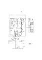
Как показано на Фиг. 1, цистерна 2 для хранения СПГ (которая может быть одной из нескольких) расположена на борту океанского танкера (не показан). Цистерна 2 покрыта изоляцией или имеет другой вид теплоизоляции, связанный с нею, чтобы не допустить притока тепла из окружающей среды в находящуюся в ней жидкость. Цистерна 2 имеет свободное пространство 4 и вмещает объем 6 СПГ. Поскольку СПГ кипит при температуре заметно ниже температуры окружающей среды, не смотря на теплоизоляцию цистерны 2, происходит непрерывное испарение СПГ в свободное пространство 4. Полученный испарившийся газ высвобождается из цистерны 2 через выход 8 и проходит по трубопроводу 10 в компрессор (или устройство для принудительного охлаждения) 12. Компрессор 12 можно приводить в действие с помощью электромотора 14. Давление газа возрастает при работе компрессора 12. Теплота сжатия обычно достаточна для роста температуры сжимаемого газа до подходящих температур, требуемых для подачи в двигатели, такие как 4-тактовые дизельные двигатели низкого давления. Однако получающийся сжатый газ может, следовательно, проходить через нагреватель 16 газа, в котором он может нагреваться паром (или другой нагревающей средой, например, горячей водой) для доведения его температуры до требуемой температуры. Во избежание перегрева газа, контроль температуры обеспечивают с помощью обводной линии 20 с клапаном, проходящей со стороны выше по потоку к стороне ниже по потоку от нагревателя 16 газа. В качестве дополнительной меры контроля температуры, нагреватель газа имеет со стороны выше по потоку клапан-регулятор 18 потока, который можно установить так, чтобы выбрать температуру выпуска из него.As shown in FIG. 1, a LNG storage tank 2 (which may be one of several) is located on board an ocean tanker (not shown). The
Второй поток выходит из цистерны 2 для хранения. Этот второй поток представляет собой поток испарившегося природного газа, который образуется при использовании принудительного испарителя 24 для испарения потока СПГ, взятого погружным насосом 26 из объема 6 СПГ, находящегося внутри цистерны 2. Выпускное отверстие насоса 26 сообщается с принудительным испарителем 24 посредством вертикальной трубы 28. Клапан-регулятор 34 давления открывает трубу 36 для обеспечения возврата жидкости в цистерну 2 для хранения для обеспечения различных скоростей потока через испаритель 24. Принудительный испаритель 24 имеет увеличенную секцию перегрева для легкого достижения температуры выпуска на уровне плюс 20°С. Расположение клапанов в принудительном испарителе 24 аналогично расположению, относящемуся к нагревателю 16 газа. Таким образом, первый клапан-регулятор 30 потока находится со стороны выше по потоку от испарителя 24 для установления давления на выпуске из нагревателя 16, чтобы оно равнялось давлению на выпуске из компрессора 12, а клапан обводной линии 32, расположенной со стороны выше по потоку к стороне ниже по потоку от испарителя 24, - для регулирования температуры выпуска пара. Испаритель 24 обычно относится к типу, использующему нагревание паром для роста температуры текучей среды, протекающей через него.A second stream
Второй поток газа подают в первый поток газа (выходящий из цистерны для хранения по трубопроводу 10) через контур 22, расположенный ниже по потоку от компрессора 12 и выше по потоку от нагревателя 18.The second gas stream is fed into the first gas stream (leaving the storage tank via line 10) through a
Газ, выходящий из нагревателя 16 газа, можно использовать для подачи в двигатели 38, работающие на двух видах топлива, которые расположены в машинном отделении 40 танкера.The gas leaving the
Устройство по настоящему изобретению предпочтительно имеет различные меры безопасности, чтобы справиться с любыми неожиданными условиями эксплуатации. Например, различные клапаны используются способом, известным специалисту в данной области техники. Некоторые клапаны показаны на рисунках, но не описаны в описании данной заявки.The device of the present invention preferably has various safety measures to cope with any unexpected operating conditions. For example, various valves are used in a manner known to one skilled in the art. Some valves are shown in the figures, but are not described in the description of this application.
В условиях, когда естественно испаряющийся газ (NBO) является относительно теплым, может быть необходимо понизить его температуру. NBO поступает в предварительный охладитель 52 оросительного типа, где небольшое количество СПГ смешивают с NBO для понижения температуры. Это может привести к образованию капель, обработку которых осуществляют ниже по потоку от предварительного охладителя 52 оросительного типа. Во избежание того, что газ в компрессоре 12 содержит капли в жидкости, сосуд 42 для разделения фаз, в котором жидкость отделяется от газа, расположен на трубопроводе 10. Жидкость возвращается через контур в зону цистерны 2 для хранения, предпочтительно ниже поверхности жидкости (в объеме 6). Данный сосуд для разделения фаз относится к естественно испаряющемуся газу (NBO). Второй сосуд 44 для фазового разделения также предусмотрен для принудительно испаряемого газа (FBO). Жидкость можно сливать из сосуда 44 через нижнее выпускное отверстие и подводить с помощью контура в цистерну 2 для хранения (предпочтительно в объем 6). Полученный природный газ, освобожденный от частиц жидкости, выходит из верхней части фазового сепаратора 44 и при низкой или сверхнизкой температуре смешивается с природным газом из компрессора 12 в зоне, находящейся выше по потоку относительно нагревателя 16 газа.In conditions where naturally evaporating gas (NBO) is relatively warm, it may be necessary to lower its temperature. NBO enters the pre-cooler 52 of the irrigation type, where a small amount of LNG is mixed with NBO to lower the temperature. This can lead to the formation of droplets, the processing of which is carried out downstream of the pre-cooler 52 irrigation type. In order to avoid that the gas in the
На Фиг. 1 (а также на Фиг. 2 и 3) показаны только основные элементы. Элементы, такие как, например, пусковая/растопочная линия, объединение со вторым компрессором, резервный испаритель, второй нагреватель и т.д., не представлены).In FIG. 1 (and also in FIGS. 2 and 3) only the main elements are shown. Elements such as, for example, a start / start line, combining with a second compressor, a backup evaporator, a second heater, etc., are not shown).
Если необходимо, фазовый сепаратор 42 и/или 44 может быть снабжен в зоне около его верхней части набивкой с абсорбирующим материалом или проволочной сеткой, которые могут поглощать любые оставшиеся капли СПГ из газа в газовом сепараторе. Жидкость можно сливать из сосуда 42 и/или 44 через нижнее выпускное отверстие непрерывно или через регулярные промежутки времени и возвращать в цистерну 2 посредством соответствующей операции и с помощью клапана-регулятора (не показан).If necessary, the
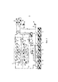
На Фиг. 2 представлено воплощение изобретения с несколькими цистернами 2 для хранения. Это воплощение демонстрирует, что FBO отбирают из нескольких (1, 2 или в конечном счете большего количества) цистерн. На Фиг. 2 показана также вентиляционная шахта 46, находящаяся в соединении с выпускными отверстиями 8 цистерны 2 через клапан-регулятор 48. Также показан блок 50 сжигания газа (CGU), в котором можно сжигать газ.In FIG. 2 shows an embodiment of the invention with
Структура устройства, показанная на Фиг. 2, такая же, как структура устройства на Фиг. 1. Для потока первого газа, чтобы минимизировать требования по теплу (и, следовательно, мощности) компрессора, NBO обычно охлаждают во время порожнего рейса с помощью предварительного охладителя 52 оросительного типа, находящегося выше по потоку от компрессора 12. Фазовый сепаратор 42 является каплеотбойником для NBO и установлен между предварительным охладителем 52 оросительного типа и компрессором 12 для защиты компрессора от возможного переноса капель. Конденсат возвращают в цистерну 2 при использовании осушительного колодца под давлением (не показан). Доохладитель 54 обеспечивают в каждой из линий для двигателей, работающих на двух видах топлива, в машинном отделении 40 и в GCU 50 для обеспечения любого требуемого изменения температуры.The structure of the device shown in FIG. 2 is the same as the structure of the device in FIG. 1. For the first gas stream, in order to minimize the heat (and therefore power) requirements of the compressor, NBOs are usually cooled during an empty run using an
Для потока второго газа, обеспечивают принудительный испаритель для генерации FBO, чтобы разбавлять газовое топливо, если характеристики NBO окажутся неприемлемыми. Подача жидкости в принудительный испаритель 24 происходит либо с помощью предназначенных для газового топлива насосов 26, которые установлены в двух из указанных цистерн, либо с помощью оросительных насосов (не показаны).For a second gas stream, a forced vaporizer is provided to generate FBO to dilute the gas fuel if NBO characteristics are not acceptable. The liquid is supplied to the forced
Поскольку нагнетаемый газ содержит все компоненты СПГ, доля тяжелых углеводородов будет оказывать негативное воздействие на метановое число газа, поступающего в двигатель. Для улучшения метанового числа в таких обстоятельствах температуру нагнетания уменьшают и FBO каплеотбойник (второй фазовый сепаратор 44) устанавливают после принудительного испарителя 24 для удаления конденсата. Он удаляет большую долю тяжелых углеводородов, которые возвращают в цистерны 2.Since the injected gas contains all the LNG components, the proportion of heavy hydrocarbons will have a negative effect on the methane number of the gas entering the engine. In order to improve the methane number in such circumstances, the discharge temperature is reduced and the FBO droplet eliminator (second phase separator 44) is installed after the forced
Потоки NBO и FBO объединяют после компрессора 12 для газового топлива. Затем объединенный поток пропускают через нагреватель 16 (малой производительности) для газового топлива перед направлением в двигатель(и) в машинном отделении 40.The NBO and FBO streams are combined after the
GCU 50 (или тепловой окислитель 56, показанный на Фиг. 1) обеспечивают во избежание избытка NBO в условиях низкой загрузки двигателя, когда потребление ниже, чем подача NBO. Его можно использовать в том случае, когда компрессор пропускает газ, пока охлаждают линии впуска.The GCU 50 (or thermal oxidizer 56 shown in FIG. 1) provide to avoid excess NBO in low engine load conditions when consumption is lower than the NBO feed. It can be used when the compressor passes gas while the intake lines are cooled.
Дополнительное газовое топливо подают с помощью предназначенных для этого высоконапорных насосов для газового топлива и подают в принудительный испаритель 24. Нагнетаемый газ направляют в каплеотбойник для FBO (фазовый сепаратор 44), где тяжелые углеводороды удаляет и возвращают в цистерну под давлением системы.Additional gas fuel is supplied by means of high-pressure gas fuel pumps designed for this purpose and fed to a forced
На Фиг. 3 показано другое воплощение устройства для обработки по изобретению. В этом воплощении предлагают два компрессора 12. Каждый компрессор 12 имеет шесть ступеней и включает также два промежуточных охладителя 58 и доохладитель 60. Первый промежуточный охладитель 58 расположен в петле, соединяющей выпускное отверстие первой ступени с ее впускным отверстием. Второй промежуточный охладитель 58 расположен последовательно между третьей и четвертой ступенями рассматриваемого компрессора 12. Доохладитель 60 расположен ниже по потоку относительно шестой ступени и позволяет регулировать температуру потока сжатого газа.In FIG. 3 shows another embodiment of a processing device according to the invention. In this embodiment, two
В этом воплощении можно достигать двух разных давлений. Данное устройство для обработки может подавать, например, в двигатели в машинном отделении 40, но также в генератор 62 или другой тип потребляющего устройства.In this embodiment, two different pressures can be achieved. This processing device can be fed, for example, to engines in the
Как можно видеть, в данном воплощении отсутствует нагреватель после компрессоров 12. FBO газ смешивают с сжатым NBO газом ниже по потоку относительно компрессоров 12 (в представленном воплощении также ниже по потоку относительно доохладителей 60), выше по потоку относительно генератора 62 и двигателей машинного отделения 40.As you can see, in this embodiment there is no heater after the
Для регулирования состояния газа, выходящего из второго потока (FBO), до состояния сжатого газа, выходящего из первого потока (NBO), также предусмотрен нагреватель 64, расплолженный ниже по потоку относительно фазового сепаратора 44. Газ, выходящий из нагревателя 64, затем смешивают со сжатым NBO газом. Давление газа (NBO и FBO) составляет, например, от 1 МПа до 2 МПа (от 10 до 20 бар). Если компрессоры 12 достигают двух разных давлений, FBO газ можно смешивать с газом, выходящим только из одного из компрессоров 12, или может быть предусмотрена вторая линия с FBO.To control the state of the gas leaving the second stream (FBO) to the state of the compressed gas leaving the first stream (NBO), a
На Фиг. 3 показана также установка 62 для повторного сжижения. В случае избытка NBO газа, лишний газ можно повторно сжижить и направить обратно в цистерны 2, тем самым сохраняя груз.In FIG. 3 also shows a
Устройство, описанное выше в данной заявке, удовлетворяет условиям, необходимым для оптимальной эффективной работы 2-тактовых двигателей, работающих на двух видах топлива при низком давлении. Оно включает признаки, которые максимизируют доступную эффективность двигателей, поддерживая при этом условия, подходящие для работы многоступенчатых компрессоров, нагревателей и испарителей.The device described above in this application satisfies the conditions necessary for optimal efficient operation of 2-stroke engines operating on two types of fuel at low pressure. It includes features that maximize the available engine efficiency while maintaining conditions suitable for multi-stage compressors, heaters and evaporators.
Согласно предпочтительному воплощению устройства по изобретению, размеры компрессоров должны соответствовать емкости, подходящей для естественно испаряемого газа. Это позволяет снизить емкость и установочную мощность. Предлагаемое кондиционирование FBO улучшает состав газа и обеспечивает более широкие пределы эксплуатации, которые иначе ограничивались бы эффектами более низкого метанового числа.According to a preferred embodiment of the device according to the invention, the sizes of the compressors must correspond to a container suitable for naturally evaporating gas. This reduces capacity and installation power. The proposed FBO conditioning improves the composition of the gas and provides wider operating limits that would otherwise be limited by the effects of lower methane numbers.
Давление, создаваемое насосом для газового топлива, сохраняется и используется после принудительного испарителя. Это сохраняет подводимую от насоса мощность и значительно снижает мощность приводного устройства компрессора.The pressure generated by the gas fuel pump is stored and used after the forced evaporator. This saves the power supplied from the pump and significantly reduces the power of the compressor drive unit.
Корректное регулирование системы подачи газового топлива и вспомогательного оборудования (оросительные насосы, GCU и т.д.) обеспечат бесперебойную работу в автоматическом режиме для всех режимов работы.Correct regulation of the gas fuel supply system and auxiliary equipment (irrigation pumps, GCU, etc.) will ensure uninterrupted operation in automatic mode for all operating modes.
Согласно изобретению, предложена экономичная система для обработки испаряемого газа, которая обеспечивает значительные преимущества в отношении требований по комплексному обращению с газовым топливом на судне по транспортировке СПГ с 2-тактовыми двигателями, работающими на двух видах топлива, низкого давления.According to the invention, an economical system for the treatment of vaporized gas is proposed, which provides significant advantages with respect to the requirements for the integrated management of gas fuel on a LNG transport vessel with 2-stroke engines operating on two types of low-pressure fuel.
Хотя изобретение было проиллюстрировано и подробно описано на чертежах и в описании, такую иллюстрацию и описание следует рассматривать в виде иллюстрации или примера, а не как ограничивающие изобретение до его раскрытых воплощений. Изменения раскрытых воплощений может быть понятно специалисту в данной области техники и осуществлено при реализации заявленного изобретения, на основе чертежей, описания и прилагаемой формулы изобретения.Although the invention has been illustrated and described in detail in the drawings and description, such illustration and description should be considered as an illustration or example, and not as limiting the invention to its disclosed embodiments. Changes to the disclosed embodiments may be understood by one of ordinary skill in the art and may be made by implementing the claimed invention, based on the drawings, description and appended claims.
Claims (17)
Applications Claiming Priority (1)
| Application Number | Priority Date | Filing Date | Title |
|---|---|---|---|
| PCT/CN2015/092069 WO2017063182A1 (en) | 2015-10-16 | 2015-10-16 | Method of an apparatus for treating boil-off gas for the purposes of supplying at least an engine |
Publications (1)
| Publication Number | Publication Date |
|---|---|
| RU2696145C1 true RU2696145C1 (en) | 2019-07-31 |
Family
ID=58517000
Family Applications (1)
| Application Number | Title | Priority Date | Filing Date |
|---|---|---|---|
| RU2018116032A RU2696145C1 (en) | 2015-10-16 | 2015-10-16 | Method and device for treating evaporated gas for feeding at least to an engine |
Country Status (7)
| Country | Link |
|---|---|
| US (1) | US10816140B2 (en) |
| EP (1) | EP3362353A4 (en) |
| JP (1) | JP6821675B2 (en) |
| KR (1) | KR102324448B1 (en) |
| CN (1) | CN108137145A (en) |
| RU (1) | RU2696145C1 (en) |
| WO (1) | WO2017063182A1 (en) |
Families Citing this family (4)
| Publication number | Priority date | Publication date | Assignee | Title |
|---|---|---|---|---|
| CN108137132B (en) * | 2015-11-05 | 2020-04-14 | 现代重工业株式会社 | Gas treatment system and ship comprising same |
| JP7143120B2 (en) * | 2018-06-01 | 2022-09-28 | 株式会社神戸製鋼所 | gas supply system |
| CN108857916B (en) * | 2018-08-21 | 2024-04-09 | 中国石油集团工程技术研究有限公司 | Sand blasting rust removal mobile workstation |
| JP6966661B1 (en) * | 2021-03-31 | 2021-11-17 | 三菱造船株式会社 | Ship |
Citations (7)
| Publication number | Priority date | Publication date | Assignee | Title |
|---|---|---|---|---|
| EP1291576A2 (en) * | 2001-08-24 | 2003-03-12 | Cryostar-France SA | Natural gas supply apparatus |
| EP1348620A1 (en) * | 2002-03-26 | 2003-10-01 | Alstom | Arrangement for supplying gaseous fuel to a power plant in a LNG ship |
| CN1707151A (en) * | 2004-05-14 | 2005-12-14 | 阿尔斯通股份有限公司 | Installation for delivering combustible gas to a energy generator of a ship transporting liquefied gas |
| WO2008075882A1 (en) * | 2006-12-18 | 2008-06-26 | Samsung Heavy Ind. Co., Ltd. | Fuel supply apparatus of liquefied gas carrier and fuel supply method thereof |
| US20090126400A1 (en) * | 2005-01-21 | 2009-05-21 | Josef Pozivil | Natural Gas Supply Method and Apparatus |
| WO2014209029A1 (en) * | 2013-06-26 | 2014-12-31 | 대우조선해양 주식회사 | System and method for treating boil-off gas in ship |
| KR20150042405A (en) * | 2013-10-11 | 2015-04-21 | 삼성중공업 주식회사 | System having re-liquefaction device to supply dual pressure fuel gas |
Family Cites Families (17)
| Publication number | Priority date | Publication date | Assignee | Title |
|---|---|---|---|---|
| JPS6354938U (en) * | 1986-09-26 | 1988-04-13 | ||
| NO176454C (en) * | 1993-01-29 | 1995-04-05 | Kvaerner Moss Tech As | Methods and plants for utilizing and providing fuel gas, respectively |
| MY118329A (en) * | 1995-04-18 | 2004-10-30 | Shell Int Research | Cooling a fluid stream |
| CN1112505C (en) * | 1995-06-01 | 2003-06-25 | 特雷克特贝尔Lng北美公司 | Liquefied natural gas (LNG) fueled combined cycle power plant and LNG fueled gas turbine plant |
| JP4240589B2 (en) * | 1998-07-09 | 2009-03-18 | 株式会社Ihi | Method of starting operation of low-temperature gas turbocompressor |
| JP2000146094A (en) * | 1998-11-11 | 2000-05-26 | Ishikawajima Harima Heavy Ind Co Ltd | Bog compressor |
| GB0400986D0 (en) * | 2004-01-16 | 2004-02-18 | Cryostar France Sa | Compressor |
| EP2072885A1 (en) * | 2007-12-21 | 2009-06-24 | Cryostar SAS | Natural gas supply method and apparatus. |
| JP2010223424A (en) * | 2009-02-27 | 2010-10-07 | Mitsubishi Heavy Ind Ltd | Vaporized gas supply device |
| JP2012076561A (en) * | 2010-09-30 | 2012-04-19 | Mitsubishi Heavy Ind Ltd | Fuel supply system for ship |
| EP2690274A4 (en) * | 2011-03-22 | 2016-07-13 | Daewoo Shipbuilding&Marine Engineering Co Ltd | System for supplying fuel to high-pressure natural gas injection engine having excess evaporation gas consumption means |
| JP2014514486A (en) * | 2011-03-22 | 2014-06-19 | デウ シップビルディング アンド マリーン エンジニアリング カンパニー リミテッド | Fuel supply system and method for a high pressure natural gas injection engine |
| KR101386543B1 (en) * | 2012-10-24 | 2014-04-18 | 대우조선해양 주식회사 | System for treating boil-off gas for a ship |
| KR101350807B1 (en) * | 2012-10-24 | 2014-01-16 | 대우조선해양 주식회사 | Hybrid fuel supply system for ship engine |
| EP2746707B1 (en) * | 2012-12-20 | 2017-05-17 | Cryostar SAS | Method and apparatus for reliquefying natural gas |
| FR3004513B1 (en) * | 2013-04-11 | 2015-04-03 | Gaztransp Et Technigaz | METHOD AND SYSTEM FOR PROCESSING AND DELIVERING NATURAL GAS TO ENERGY PRODUCTION EQUIPMENT FOR VESSEL PROPULSION |
| KR20150092771A (en) * | 2014-01-27 | 2015-08-17 | 현대중공업 주식회사 | A Treatment System Of Liquefied Gas |
-
2015
- 2015-10-16 US US15/768,220 patent/US10816140B2/en active Active
- 2015-10-16 CN CN201580083884.4A patent/CN108137145A/en active Pending
- 2015-10-16 JP JP2018519405A patent/JP6821675B2/en active Active
- 2015-10-16 EP EP15906067.2A patent/EP3362353A4/en active Pending
- 2015-10-16 RU RU2018116032A patent/RU2696145C1/en active
- 2015-10-16 WO PCT/CN2015/092069 patent/WO2017063182A1/en active Application Filing
- 2015-10-16 KR KR1020187010563A patent/KR102324448B1/en active IP Right Grant
Patent Citations (7)
| Publication number | Priority date | Publication date | Assignee | Title |
|---|---|---|---|---|
| EP1291576A2 (en) * | 2001-08-24 | 2003-03-12 | Cryostar-France SA | Natural gas supply apparatus |
| EP1348620A1 (en) * | 2002-03-26 | 2003-10-01 | Alstom | Arrangement for supplying gaseous fuel to a power plant in a LNG ship |
| CN1707151A (en) * | 2004-05-14 | 2005-12-14 | 阿尔斯通股份有限公司 | Installation for delivering combustible gas to a energy generator of a ship transporting liquefied gas |
| US20090126400A1 (en) * | 2005-01-21 | 2009-05-21 | Josef Pozivil | Natural Gas Supply Method and Apparatus |
| WO2008075882A1 (en) * | 2006-12-18 | 2008-06-26 | Samsung Heavy Ind. Co., Ltd. | Fuel supply apparatus of liquefied gas carrier and fuel supply method thereof |
| WO2014209029A1 (en) * | 2013-06-26 | 2014-12-31 | 대우조선해양 주식회사 | System and method for treating boil-off gas in ship |
| KR20150042405A (en) * | 2013-10-11 | 2015-04-21 | 삼성중공업 주식회사 | System having re-liquefaction device to supply dual pressure fuel gas |
Also Published As
| Publication number | Publication date |
|---|---|
| US10816140B2 (en) | 2020-10-27 |
| KR102324448B1 (en) | 2021-11-10 |
| JP6821675B2 (en) | 2021-01-27 |
| KR20180078234A (en) | 2018-07-09 |
| EP3362353A4 (en) | 2019-07-31 |
| WO2017063182A1 (en) | 2017-04-20 |
| JP2018531833A (en) | 2018-11-01 |
| EP3362353A1 (en) | 2018-08-22 |
| CN108137145A (en) | 2018-06-08 |
| US20180313497A1 (en) | 2018-11-01 |
Similar Documents
| Publication | Publication Date | Title |
|---|---|---|
| JP6873116B2 (en) | Gas treatment system and ships including it | |
| KR102090177B1 (en) | Ship | |
| JP6628328B2 (en) | Ships including gas treatment systems | |
| KR101941357B1 (en) | A Regasification System Of Gas and Vessel having the same | |
| JP5538234B2 (en) | Natural gas supply method and apparatus | |
| KR101314337B1 (en) | Natural gas supply method and apparatus | |
| KR101904367B1 (en) | Utilization of lng used for fuel to liquefy lpg boil off | |
| WO2009136793A1 (en) | Gas supply systems for gas engines | |
| KR20170091490A (en) | A Vessel having a regasification System of gas | |
| RU2719258C2 (en) | System and method of treating gas obtained during cryogenic liquid evaporation | |
| KR20200012673A (en) | Boil-off gas cooling system and ship having the same | |
| RU2696145C1 (en) | Method and device for treating evaporated gas for feeding at least to an engine | |
| JP6732946B2 (en) | Equipment for feeding a flammable gas to a gas consuming member and liquefying the flammable gas | |
| KR20180025584A (en) | Gas treatment system and ship having the same | |
| KR102232229B1 (en) | Volatile organic compounds treatment system and ship having the same | |
| KR20190070469A (en) | Gas treatment system and ship having the same | |
| KR20190028097A (en) | Gas Treatment System and Vessel having the same | |
| KR102288013B1 (en) | Reliquefaction system for boil-off gas and ship having the same | |
| KR20180025585A (en) | Gas treatment system and ship having the same | |
| KR20180041923A (en) | Treatment system of gas and ship having the same | |
| KR20160096564A (en) | Apparatus for retreating boil off gas | |
| KR102296310B1 (en) | Treatment system of gas and ship having the same | |
| KR102348832B1 (en) | gas treatment system and ship having the same | |
| KR102552735B1 (en) | liquefied gas treatment system and ship having the same | |
| KR102372229B1 (en) | Treatment system of liquefied gas and vessel having the same |