EP2911965B1 - Vorrichtung und verfahren zur positionierung eines dokuments - Google Patents
Vorrichtung und verfahren zur positionierung eines dokuments Download PDFInfo
- Publication number
- EP2911965B1 EP2911965B1 EP13783527.8A EP13783527A EP2911965B1 EP 2911965 B1 EP2911965 B1 EP 2911965B1 EP 13783527 A EP13783527 A EP 13783527A EP 2911965 B1 EP2911965 B1 EP 2911965B1
- Authority
- EP
- European Patent Office
- Prior art keywords
- document
- positioning
- feed surface
- positioning means
- contact
- Prior art date
- Legal status (The legal status is an assumption and is not a legal conclusion. Google has not performed a legal analysis and makes no representation as to the accuracy of the status listed.)
- Active
Links
Images


Classifications
-
- B—PERFORMING OPERATIONS; TRANSPORTING
- B65—CONVEYING; PACKING; STORING; HANDLING THIN OR FILAMENTARY MATERIAL
- B65H—HANDLING THIN OR FILAMENTARY MATERIAL, e.g. SHEETS, WEBS, CABLES
- B65H5/00—Feeding articles separated from piles; Feeding articles to machines
- B65H5/08—Feeding articles separated from piles; Feeding articles to machines by grippers, e.g. suction grippers
- B65H5/14—Details of grippers; Actuating-mechanisms therefor
-
- B—PERFORMING OPERATIONS; TRANSPORTING
- B42—BOOKBINDING; ALBUMS; FILES; SPECIAL PRINTED MATTER
- B42D—BOOKS; BOOK COVERS; LOOSE LEAVES; PRINTED MATTER CHARACTERISED BY IDENTIFICATION OR SECURITY FEATURES; PRINTED MATTER OF SPECIAL FORMAT OR STYLE NOT OTHERWISE PROVIDED FOR; DEVICES FOR USE THEREWITH AND NOT OTHERWISE PROVIDED FOR; MOVABLE-STRIP WRITING OR READING APPARATUS
- B42D25/00—Information-bearing cards or sheet-like structures characterised by identification or security features; Manufacture thereof
- B42D25/40—Manufacture
- B42D25/405—Marking
- B42D25/41—Marking using electromagnetic radiation
-
- B—PERFORMING OPERATIONS; TRANSPORTING
- B65—CONVEYING; PACKING; STORING; HANDLING THIN OR FILAMENTARY MATERIAL
- B65H—HANDLING THIN OR FILAMENTARY MATERIAL, e.g. SHEETS, WEBS, CABLES
- B65H5/00—Feeding articles separated from piles; Feeding articles to machines
- B65H5/16—Feeding articles separated from piles; Feeding articles to machines by pusher, needles, friction, or like devices adapted to feed single articles along a surface or table
-
- B—PERFORMING OPERATIONS; TRANSPORTING
- B65—CONVEYING; PACKING; STORING; HANDLING THIN OR FILAMENTARY MATERIAL
- B65H—HANDLING THIN OR FILAMENTARY MATERIAL, e.g. SHEETS, WEBS, CABLES
- B65H9/00—Registering, e.g. orientating, articles; Devices therefor
- B65H9/10—Pusher and like movable registers; Pusher or gripper devices which move articles into registered position
-
- B—PERFORMING OPERATIONS; TRANSPORTING
- B65—CONVEYING; PACKING; STORING; HANDLING THIN OR FILAMENTARY MATERIAL
- B65H—HANDLING THIN OR FILAMENTARY MATERIAL, e.g. SHEETS, WEBS, CABLES
- B65H9/00—Registering, e.g. orientating, articles; Devices therefor
- B65H9/10—Pusher and like movable registers; Pusher or gripper devices which move articles into registered position
- B65H9/101—Pusher and like movable registers; Pusher or gripper devices which move articles into registered position acting on the edge of the article
-
- B—PERFORMING OPERATIONS; TRANSPORTING
- B65—CONVEYING; PACKING; STORING; HANDLING THIN OR FILAMENTARY MATERIAL
- B65H—HANDLING THIN OR FILAMENTARY MATERIAL, e.g. SHEETS, WEBS, CABLES
- B65H2405/00—Parts for holding the handled material
- B65H2405/50—Gripping means
- B65H2405/52—Gripping means reciprocating
-
- B—PERFORMING OPERATIONS; TRANSPORTING
- B65—CONVEYING; PACKING; STORING; HANDLING THIN OR FILAMENTARY MATERIAL
- B65H—HANDLING THIN OR FILAMENTARY MATERIAL, e.g. SHEETS, WEBS, CABLES
- B65H2405/00—Parts for holding the handled material
- B65H2405/50—Gripping means
- B65H2405/57—Details of the gripping parts
-
- B—PERFORMING OPERATIONS; TRANSPORTING
- B65—CONVEYING; PACKING; STORING; HANDLING THIN OR FILAMENTARY MATERIAL
- B65H—HANDLING THIN OR FILAMENTARY MATERIAL, e.g. SHEETS, WEBS, CABLES
- B65H2701/00—Handled material; Storage means
- B65H2701/10—Handled articles or webs
- B65H2701/19—Specific article or web
- B65H2701/1914—Cards, e.g. telephone, credit and identity cards
-
- B—PERFORMING OPERATIONS; TRANSPORTING
- B65—CONVEYING; PACKING; STORING; HANDLING THIN OR FILAMENTARY MATERIAL
- B65H—HANDLING THIN OR FILAMENTARY MATERIAL, e.g. SHEETS, WEBS, CABLES
- B65H2701/00—Handled material; Storage means
- B65H2701/10—Handled articles or webs
- B65H2701/19—Specific article or web
- B65H2701/1926—Opened booklet
Definitions
- the invention relates to an apparatus and a method for positioning a document.
- the invention relates to a collection device for a personalization system for personalizing a security document.
- Known retraction mechanisms in so-called pass personalization systems comprise a friction wheel and / or a friction belt for transporting the document from a retraction position into the personalization position. That's how it describes DE 695 12 527 T2 a machine capable of providing a method of counterfeiting, authentication or personalization of paper sheets.
- the machine includes so-called sheet feed rollers for transporting sheets to be personalized.
- Such a transport has the disadvantage that documents are positioned obliquely in the personalization position or that the document is folded as it moves in. A slanted indentation can lead to rejects, deteriorated personalization quality as well as sticking of the document in the personalization system.
- Personalization systems are also known which comprise workpiece carriers or cassettes or frames connected to the system for the collection and transport of documents. Although such mechanisms can prevent skewing and jamming of the documents, but with manual insertion of documents in the personalization plant additional work.
- the US 2008/295722 A1 discloses a plate-making process comprising pre-orientation treatment of a printing plate relative to a imaging drum of a printing plate Plate making machine as the printing plate is moved along a sheet feeding path to the plate making machine.
- the US 2007/145667 A1 discloses a method for correcting the lateral position of a printing material. This includes gripping the printing material with a transport unit, rotating the transport unit in a lateral position correction angle range for correcting the lateral position of the printing material, and rotating the transport unit from the lateral position correction angle range while maintaining the correction of the lateral position of the printing material.
- the EP 2 415 700 A2 discloses a device for aligning a flat product.
- the device has an alignment unit which is arranged above a conveying surface.
- the alignment unit is provided so that force transferred to a surface changes the position of a flat product relative to the conveying surface.
- the DE 199 56 712 A1 discloses a holding device for holding a book-like document having a plurality of sheets during a printing operation on at least one side of the book-like document.
- the holding device has a clamping device, which clamps at least one sheet of the book-like document, wherein the clamping device has three wedges.
- the technical problem arises of providing a device and a method for positioning a document, in particular for positioning a security document in a personalization system, which increases the accuracy of the positioning, minimizes damage to the document during positioning and simplifies operability.
- a device for positioning a document is proposed.
- the device may in this case be part of a so-called personalization system, whereby personalization of the document can be carried out by means of the personalization system is.
- Personalization includes, for example, the generation of a physical representation of personalizing and / or individualizing information in or on the document.
- a personalizing and / or individualizing information here denotes information that makes the document clearly distinguishable from other documents. Such information may be, for example, a photograph, a hologram, a document number, a serial number, a name of a holder of the document, or a signature of the owner of the document.
- Such information may represent security features or security elements. Also, further training such information is of course conceivable.
- the document may be personalized by a laser personalization system or a laser personalization device.
- a laser beam is generated by a laser and e.g. by means of mirroring on the document or in the document blasted in such a way that changes in the document structure take place in one or more layers of the document such that a graphic, in particular visible, representation of information is generated.
- the laser personalization system may comprise a laser, optical deflection means and a corresponding control device for the laser and the deflection devices.
- the laser personalization system may include a turntable with which an orientation of the document in the personalization position is changeable.
- the proposed device can be used for positioning a document from a starting position into a personalization position, in particular for inserting the document from a starting position into the personalization position.
- the personalization position here denotes a predetermined position in which the document is positioned with a known position and orientation to one or more personalization means.
- a position and / or orientation of the document relative to a global coordinate system is known.
- a position range and / or orientation range of the document may be known in the personalization position, wherein the positioning in the personalization position ensures that the document is at a position outside the position range and / or has an orientation from the alignment range ,
- the personalization position thus serves to position the document in a desired position and / or with a desired orientation to a personalization means, e.g. B. to the previously described laser for laser personalization.
- the device comprises at least one movable positioning means. Furthermore, the device has a feed surface. The catchment area is used for placing the document to be personalized. Further, the device may comprise a housing which z. B. is a part of a housing of the personalization system, which includes the proposed device.
- the movable positioning means is in this case movable relative to the stationary feed surface.
- the document to be personalized is moved by the movable positioning means along the feed surface from a starting or retracting position of the document to the personalization position.
- the at least one positioning means is movable in such a way that by the positioning means in a first sub-operation of the positioning process, a force normal to the feed surface, which can also be referred to as a pressing force, and a displacement force parallel to the feed surface can be exerted on a document placed on the feed surface such that the document placed on the feed surface is displaceable by a first predetermined displacement in a longitudinal positioning direction.
- a frictional connection is made between the document and the positioning means.
- the frictional connection is in this case by the for Feeding surface normal force, which is exerted by the positioning means on the document made.
- the positioning means parallel to the feed surface displacement force on the laid on the feed surface document is applied by the positioning means parallel to the feed surface displacement force on the laid on the feed surface document.
- the parallel to the feed surface displacement force can be oriented in this case in the aforementioned longitudinal positioning direction or at least have a proportion which is oriented in this direction.
- a frictional transport of the document takes place. The document is thus transported or slipped over the feed surface in the longitudinal positioning direction.
- the document can be pressed by the positioning means to a movable means for generating a counterforce and not to the stationary feed surface, wherein the movable means is part of the positioning means and moves therewith.
- the risk of scratching due to the transport along the feed surface is reduced.
- the document is positioned in an intermediate position that does not correspond to the personalization position. The first predetermined displacement is thus only part of the required complete displacement.
- the longitudinal positioning direction here denotes a main direction of the positioning, which is oriented parallel to the feed surface.
- a lateral direction denotes a direction which is also oriented parallel to the feed surface and encloses an angle of 90 ° with the longitudinal positioning direction.
- a vertical direction denotes a direction oriented perpendicular to the feed surface and perpendicular to the longitudinal positioning direction and the lateral direction.
- the at least one positioning means in a further sub-operation of the positioning is movable such that by the positioning means a parallel to the feed surface displacement force on the laid on the feed surface document is exercisable that the laid on the feed surface document by another predetermined displacement in one further predetermined positioning direction is displaceable.
- the further predetermined positioning direction is preferably the longitudinal positioning direction.
- the document is positioned in the personalization position.
- the document may be at the end of the further sub-process on a Stop a document stop, with a fitting to the document stop document is in the personalization position.
- the first predetermined displacement and the further predetermined displacement can thus give the desired complete displacement.
- the document is transported from the aforementioned intermediate position to the personalization position.
- the document stop can be part of the proposed device or part of the personalization system and can z. B. be designed as a mechanical stop, in particular L- or U-shaped stop.
- the at least one positioning means is movable such that no force normal to the feed surface is exerted on the document placed on the feed surface by the positioning means during the further sub-operation.
- the displacement force exerted by the positioning means in the further sub-operation can be a compressive force by means of which the document is pushed into the further predetermined positioning direction.
- the at least one positioning means may be movable such that the displacement force is exerted on an edge or side surface of the document placed on the feed surface or on an edge or side surface of a cover of a book comprising the document to be personalized.
- the edge or the side surface in this case designate a surface which can be oriented perpendicular to the feed surface.
- the edge or side surface is different in this case from a surface of the document to be personalized.
- the proposed device advantageously reduces the risk that the document to be personalized will be positioned in the personalization position askew, ie with an undesired deviation, during the positioning process. This is due, inter alia, to the fact that in the further sub-process no force normal to the feed surface is exerted on the document to be positioned. Such a normal force in particular prevents a movement of the document in the lateral direction as well as rotational movements of the document, in particular also around a rotation axis perpendicular to the feed surface.
- document can orient in a desired manner, wherein during the alignment, for example, a lateral movement of the document and / or a rotational movement of the document can take place.
- the proposed device simplifies an operation, in particular an insertion of the document to be personalized on the feed surface. Since in the first sub-operation the positioning means does not have to be positioned in the longitudinal direction in front of the document to be transported in order to push it by a compressive force as in the further sub-operation, the catchment area can be made largely free of mechanical elements. In particular, a risk of injury to an operator is thus also reduced, since the positioning means can be arranged completely within a housing of the proposed device or personalization device comprising the proposed device, whereby a user can insert the document from outside into the housing.
- the device can furthermore have guide means or elements, in particular stop elements, for the document which, in particular during the further sub-operation, lead to a movement of the document.
- the at least one positioning means is movable with two translatory degrees of freedom.
- the at least one positioning means can be movable exclusively with two translatory degrees of freedom.
- These translatory degrees of freedom may in this case allow a movement of the positioning means in the longitudinal positioning direction and in the previously explained vertical direction.
- a movement of the positioning means may in this case be a linear movement.
- the movement in or against the longitudinal positioning direction may be a linear movement and the movement in or against the vertical direction may be a linear movement.
- the device may comprise guide elements for guiding the movement of positioning means in the previously mentioned directions of movement.
- Such guide means may be for example linear bearings.
- the device may comprise drive means for moving the positioning means along the aforementioned directions of movement.
- the device may comprise a linear motor.
- the device may also comprise a rotary motor, for example a servo or stepper motor, and a gearbox for converting the rotational movement into a linear movement.
- a transmission may include, for example, a gear and a timing belt cooperating with the gear.
- the simplest possible design of drive and guide elements of the positioning means results.
- a space required for this drive means as well as production costs can be reduced.
- a control of the drive elements can be simplified.
- the device may comprise first drive means or elements which exclusively serve to move the at least one positioning means in or against the longitudinal displacement direction, and further drive means which exclusively serve to move the at least one personalization means in or against the vertical direction.
- the positioning means is designed as a gripper, wherein the gripper has at least one contact element, wherein the contact element has a first and at least one further contact surface.
- the first contact surface may be in mechanical contact with the document to be positioned during the first part of the positioning operation.
- the gripper may also have a contact counter element, wherein the document to be positioned by the contact element to the counter contact element, in particular a surface of the counter contact element, can be pressed or pressed.
- the surface of the contact counter-element may in this case be flush with the surface of the feed surface.
- the further contact surface may be in mechanical contact with the document to be positioned or a cover of a book comprising the document to be personalized.
- the contact element may be block-shaped or block-shaped, for example, wherein the first contact surface may be formed by a surface of a lower side of the contact element and the further contact surface by a rear end surface of the contact element in the longitudinal positioning direction.
- the contact element comprises a plurality of sub-elements, wherein a first sub-element has the first contact surface and a further sub-element has or forms the further contact surface.
- the individual sub-elements can in this case be mechanically interconnected.
- the gripper is designed in such a way that a part of the contact element having the first contact surface is resiliently mounted in a direction normal to the feed surface and / or a part of the contact element having the further contact surface is spring-mounted in the longitudinal positioning direction.
- the gripper may, for example, comprise a support arm, e.g. L-shaped.
- the contact element in particular a block or cuboid contact element, can be resiliently mounted in the vertical direction at a free end of the support arm of the gripper.
- the contact element may have a part element designed as a head part, wherein the head part has or forms the further contact surface and is resiliently mounted in the longitudinal direction on the spring-mounted contact block or element.
- a varying thickness or height of a document to be transported can be compensated in an advantageous manner.
- documents with different thicknesses or heights can be transported.
- the thicker or higher the document to be transported the greater a deflection of the contact element in the direction normal to the feed surface and the stronger the normal to the feed surface Force that presses or presses the document to be transported in the first part of the process to the feed surface or to a surface of the above-mentioned counter contact element.
- a varying length of the document to be positioned can be compensated for by the resilient mounting of the part having the further contact surface, for example a length which varies as a result of manufacturing tolerances.
- a length here denotes a length of the document to be positioned or a cover of a book, which comprises the document to be positioned, in the longitudinal positioning direction.
- the device comprises two positioning means, each exerting a force on a left or a right half of the document to be positioned in the first and in the further sub-process.
- the device may be designed such that the two positioning means move synchronously, ie at the same time and to the same extent. If e.g. in the first sub-process, the document to be positioned is skewed, e.g. in the further sub-process a right half of the document to be positioned during the sliding process in time before a left half of the document to a document stop. In this case, a further shift of the left half of the document is necessary to make even the left half completely hit the document stop.
- the positioning means is movable in the longitudinal positioning direction at least into a first actuating position, a first releasing position, a second actuating position and a second releasing position.
- the longitudinal positioning direction is a horizontal direction.
- the positioning means is movable in the vertical direction in the first operation position from a release state to an operation state.
- a movement from the release state to the operating state in this case denotes a movement in the vertical direction.
- the positioning means is in this case positioned such that no force is exerted on the document placed on the feed surface.
- the positioning means is not in mechanical contact with the document to be positioned.
- the positioning means, in particular the contact element of the positioning means in the release state with a predetermined vertical distance above the feed surface and / or over the surface of the contact counter-element. Accordingly, in the actuation state of the first actuation position, the positioning means, in particular the contact element of the positioning means, is in mechanical contact with the document to be positioned, in particular a surface of the document to be positioned.
- the positioning means exerts the pressing force on the document to be positioned. If the positioning means is moved in the operating position in the longitudinal positioning direction, it simultaneously exerts the displacement force parallel to the feed surface on the document to be positioned.
- the normal force can in this case be generated completely or at least partially by a spring force, which is generated by the above-described sprung mounting of the contact element.
- the positioning means, in particular the contact element of the positioning means may be located at a predetermined vertical distance above the feed surface and / or over the surface of the contact counter-element, wherein the vertical distance is smaller in the actuation state than in the release state.
- the vertical distance to be set in the actuation state can be chosen to be equal, but preferably smaller, than a minimum thickness or height of a document to be positioned, but greater than zero.
- the set vertical distance in the release state can be chosen in particular greater than a maximum thickness or height of a document to be positioned.
- the positioning means By moving from the release state to the actuation state, the document to be positioned is gripped in the first sub-operation.
- the positioning means is in the operating state and can be moved in the longitudinal displacement direction in the first release position.
- the positioning means In the first release position, the positioning means can be moved from the actuation state to a release state. In this release state in the first release position, the positioning means is movable to the second operating position.
- the positioning means can be displaced against the longitudinal displacement direction by a predetermined distance.
- the positioning means in the second operating position, the positioning means may be movable from the released state to another operating state. In this operating state, the positioning means is movable from the second operating position to the second releasing position.
- the positioning means can be moved in the longitudinal displacement direction from the second operating position to the second release position.
- the positioning means In the second release position, the positioning means is movable from the further operating state to a release state, e.g. may be equal to the release state in the first actuation position.
- the positioning means is movable from the second release position to a third operating position, wherein the positioning means is movable in the third operating position from a release state to an operating state. Further, the positioning means can be moved from the third operating position in the operating state to a third releasing position. This movement can be directed, for example, against the longitudinal displacement direction. In the third release position, the positioning means may be movable from the actuation state to a release state. This makes it possible to transport the document by a frictional transport of the personalization position in an ejection position, for example, after a successful personalization.
- the vertical distance to be set by the positioning means relative to the feed surface and / or of the contact element to the surface of the contact counter element may in this case be the same in the release states of all positions. Also, the vertical distance to be set to the feed surface and / or the surface of the counter contact element in the operating states of all positions can be the same. However, it is also possible that the vertical distance in the operating state of the second operating position is smaller than the vertical distance in the operating state of the first operating position and the third operating position.
- the positioning means may be movable to an initial position, wherein the positioning means is movable from the starting position to the first operating position.
- the starting position can be arranged, for example, in the longitudinal direction behind the ejection position.
- the device comprises a flap, wherein the flap is arranged at a front end of the feed surface in the longitudinal positioning direction. In an open state, the flap releases the feed surface. In a closed state, the flap locks the catchment area.
- the flap may be integrated into an outer wall of a housing of the proposed device or a housing of a personalization device.
- the flap in a closed state, an interior of the housing to close to the outside.
- no document in a closed state of the flap no document can be inserted into the housing.
- an open state an introduction or insertion of at least a part of the document to be personalized in the housing and on the feed surface is possible.
- the flap in an opened state, can form a part, in particular a front part in the longitudinal positioning direction, of the feed surface.
- the flap can protrude out of the housing wall in the opened state.
- the positioning means is movable to a standby position in the longitudinal positioning direction. This standby position can be equal to the previously explained third release position.
- the apparatus is configured such that the flap opens when the positioning means moves to the standby position and the flap closes when the positioning means moves out of the standby position.
- the device may be configured such that the flap is opened only or can be moved to an open state when the positioning means is in the standby position. In the standby position, a document to be transported may be in a feeder ejection position, which will be explained in more detail below.
- the device may comprise at least one device for detecting a position, in particular a longitudinal position, of the positioning means.
- this device can be connected to a device for releasing a flap movement, for example with a locking device, in terms of signal or data.
- the opening of the flap by the means for release can be done only then or released when the means for detecting a position of the positioning means generates a corresponding output signal.
- the means for detecting a position of the positioning means data or signal technology is coupled to a device for adjusting the flap.
- the flap can e.g. be opened by the means for adjusting, for example, a motor-operated device for adjustment, whenever the positioning means moves to the standby position or is in this position.
- the positioning means and a device for adjusting the flap are mechanically coupled.
- the positioning means comprise a mechanical coupling element, for example a stop tongue, wherein the device for adjusting forms a corresponding coupling element, for example a corresponding stop tongue. If the positioning means moves into the standby position, then the coupling element of the positioning means can interact with the corresponding coupling element of the device for adjustment, whereby an opening of the flap is effected.
- the means for adjusting the flap may comprise a return element, which causes the flap to close when the positioning means is moved away from the ready position and the coupling elements are no longer in mechanical contact.
- any other type of mechanical coupling such as a permanent mechanical coupling between the positioning means and the means for adjusting the flap is conceivable.
- the device for adjusting the flap can, for example, convert a linear movement of the coupling element into a rotary movement of the flap.
- the device comprises at least one means for detecting a closed state of the flap, wherein a laser device is only released when the flap is closed.
- a laser device is only released when the flap is closed.
- a laser beam can only be generated and / or blasted onto the document when the flap is closed.
- an aperture of a laser device is only opened or can be moved to an open state when the flap is closed. This represents an additional safety measure. If the flap is in an opened state, an aperture of the laser device is closed. This ensures that no laser light can inadvertently enter an eye of a user.
- the laser device can also be electronically locked or released, wherein a release or inhibit signal for the laser device is generated depending on a state of the flap.
- the means for detecting a closed state of the flap may be formed for example as a device for detecting an angular position of the flap.
- the means for detecting a closed state can also be embodied as an optical, inductive, magnetic or capacitive or further sensor.
- An output of the sensor may e.g. represent only two states, the flap in a first state, for example, closed and opened in another state.
- the device comprises at least one means for lateral alignment.
- the lateral alignment here describes a movement of the document to be personalized in a lateral direction, which is oriented perpendicular to the longitudinal positioning direction.
- the means for lateral alignment is designed and / or arranged such that a lateral displacement force can be exerted on the document placed on the feed surface such that it is in one direction perpendicular to the longitudinal positioning direction, in particular in the lateral direction, is displaceable.
- the means for lateral alignment may be designed and / or arranged such that the document placed on the feed surface after an end of the first sub-process, ie at the beginning or during the further sub-process, perpendicular to the longitudinal positioning direction, in particular in the lateral direction, is displaceable.
- the means for lateral alignment as a spring, in particular as a leaf spring, be aligned, wherein the leaf spring is deflected from a starting position when the document to be positioned during, for example, the first sub-process with an undesirable lateral displacement in the intermediate position or during the further sub-operation is moved to the personalization position.
- the leaf spring may be formed for example by a bending strip. If the spring element is deflected out of the starting or rest position, it exerts a spring force in the lateral direction on the transported document, as a result of which it is moved in the lateral direction.
- a positioning means is moved in a first parting operation such that the positioning means exerts a force applied to a feed surface normal to the feed surface force and a feed plane parallel displacement force such that the laid on the feed surface document by a first predetermined displacement in a longitudinal Positioning is moved.
- the positioning means is moved in a further sub-operation such that the positioning means on the feed surface placed on the document parallel to the feed surface displacement force such that the document placed on the feed surface by another predetermined displacement in a further predetermined displacement direction, for example the same the longitudinal positioning can be moved.
- no force normal to the feed surface can be exerted on the document placed on the feed surface.
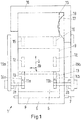
- Fig. 1 is a schematic plan view of an inventive device 1 shown.
- the device comprises a left gripper 2a and a right gripper 2b.
- the grippers 2 a, 2 b are movable in and against a longitudinal positioning direction, which is symbolized by an arrow 3.
- a lateral direction is represented by an arrow 4.
- the grippers 2 a, 2 b are movable in and against a vertical direction, wherein the vertical direction is oriented out of the plane of the drawing and is shown by an arrow 20.
- the device 1 has a feed surface 5.
- the device 1 comprises a flap 6 which is rotatable about an axis 7. In Fig. 1 the flap 6 is shown in an open state.
- a surface of the flap 6 forms a viewed in the longitudinal positioning direction 3 front part of the feed surface 5 from.
- a document to be personalized can be placed on the catchment surface 5.
- dashed lines 8 a feeder-eject position of the document is shown.
- dashed lines 9 an intermediate position of the document to be personalized and by further dashed lines 10 a personalization position of the document is shown.
- a user can place the document to be personalized on the feed surface 5 and e.g. manually slide into the feed-eject position shown by dashed lines 8.
- suitable detection means e.g. One or more photoelectric sensors are detected, whether the document is in the feeder ejection position.
- stop members may be provided which limit the insertion into the feeder ejection position 8 in the longitudinal positioning direction 3, but release the subsequent movement of the document when a subsequent insertion or ejection of the document.
- Fig. 1 It is shown that the grippers 2 a, 2 b are in a standby position with respect to the longitudinal positioning direction 3. In the standby position, a document located in the feeder ejection position 8 can be gripped by the grippers 2a, 2b. As explained in more detail below, the grippers 2a, 2b and the flap 6 are mechanically coupled such that the flap 6 is set in the open state when the grippers 2a, 2b move to the standby position. Further, the flap 6 is set in the closed state if the grippers 2 a, 2 b move out of the standby position in the longitudinal positioning direction 3. In this case, the ready position forms a frontmost position of the grippers 2 a, 2 b seen in the longitudinal positioning direction 3.
- the grippers 2a, 2b can be moved from an initial position, not shown, which is located in the longitudinal positioning direction 3 behind the standby position, in the standby position at the beginning of a positioning operation.
- the beginning of the positioning process can be triggered, for example, by a triggering operation by a user.
- the flap 6 opens and the user can place a document to be positioned on the feed surface 5 and push it into the feed ejection position 8.
- the grippers 2a, 2b are movable from a release state to an actuated state. This movement is a movement opposite to the previously explained vertical direction 20.
- Each of the grippers 2a, 2b has a contact block 11a, 11b.
- a bottom 44a (see FIG Fig. 6 ) of the contact blocks 11 a, 11 b with a surface of the in the ejection-ejection position eighth document in mechanical contact.
- a force normal to the feed surface 5, which is oriented counter to the vertical direction 20 exerted on the document, whereby the document with the grippers 2a, 2b is frictionally connected.
- the document is pressed in the actuation state of the contact block 11a, 11b against a contact counter block 62a, 62b, wherein the contact counter block 62a, 62b generates a force oriented opposite to the normal force (see, for example Fig. 5 ).
- the document between the contact block 11a, 11b and the contact counter block 62a, 62b is clamped.
- the document is not pressed against the feed surface 5 by the contact blocks 11a, 11b.
- a predetermined vertical distance of the contact block 11a, 11b from the feed surface 5 and from a vertically upper surface of the contact counter blocks 62a, 62b is set such that the lower surfaces 44a of the contact blocks 11a, 11b are not in mechanical contact with the surface of the launched document.
- a predetermined vertical distance of the contact block 11a, 11b from the feed surface 5 and from the vertically upper surface of the contact counter blocks 62a, 62b is adjusted so that the lower surfaces 44a of the contact blocks 11a, 11b are in mechanical contact with the surface of the issued document.
- the grippers 2 a, 2 b are moved in the longitudinal positioning direction 3 to a first release position, which is shown by dashed-dotted lines 12.
- the contact blocks 11a, 11b remain in the operating state.
- a force acting in the longitudinal positioning direction 3 is exerted on the document.
- the document is moved from the intake-ejection position 8 in the intermediate position 9, in particular moved.
- the ready position corresponds to a first operating position.
- the grippers 2a, 2b move from the standby position (from the first operating position), the flap 6 is automatically closed.
- the contact blocks 11a, 11b are moved from the actuation state to the release state, that is, moved in the vertical direction 20.
- the mechanical contact of the lower surfaces 44a of the contact blocks 11a, 11b solved with the surface of the document and no more normal to the feed surface 5 force exerted on the document.
- the grippers 2 a, 2 b are movable counter to the longitudinal positioning direction 3 into a second actuation position, which is represented by colon dashed lines 13.
- the contact blocks 11a, 11b are moved from the release state to an operating state.
- a rear end side 14a, 14b of the contact blocks 11a, 11b in the longitudinal positioning direction 3 is positioned in front of a front edge of the intermediate position 9 in the longitudinal positioning direction 3 and thus of the document to be positioned or a cover of a book which comprises the document to be positioned , is positioned.
- the rear end faces 14a, 14b in this case have an end-face contact surface 55a (see Fig. 6 ) on.
- the grippers 2a, 2b are moved in the longitudinal positioning direction 3 by a further predetermined displacement to a second release position, which is shown by dotted lines 15, wherein the contact blocks 11a, 11b during this movement in the operating state are located.
- a second release position which is shown by dotted lines 15, wherein the contact blocks 11a, 11b during this movement in the operating state are located.
- the document located in the intermediate position 9 is pushed into the personalization position 10.
- no force normal to the draw-in surface 5 is exerted on the document by the contact blocks 11a, 11bs.
- the contact blocks 11a, 11b are moved from the actuation state to the release state.
- This movement is preferably composed of a first partial movement in opposition to the longitudinal positioning direction 3 and a second partial movement in the vertical direction 3 subsequent to the first partial movement in order to damage a margin of the document or cover of a book comprising the document during the movement To avoid movement.
- Fig. 1 It is shown that the document in the personalization position abuts against or abuts a U-shaped document stop 16. Thus, the document is after the further sub-process in a predetermined position in which a personalization, for example by a laser engraving, can take place.
- a spring element 17 which is formed by a metal strip under tension.
- Fig. 1 are schematically illustrated linear guides 19a, 19b of the gripper 2a, 2b.
- the grippers 2 a, 2 b can be moved in the release state into a third actuation position, which lies, for example, in the longitudinal positioning direction 3 behind the second release position 15.
- the contact blocks 11a, 11b can be moved from the release state to an operating state.
- lower surfaces 44a of the contact blocks 11a, 11b again come into mechanical contact with the surface of the now personalized document.
- the grippers 2a, 2b can then be moved from the third operating position to the standby position, wherein a force is exerted against the longitudinal positioning direction 3 on the document. This is thus moved against the longitudinal positioning direction 3 on the feed surface 5 and moved to the feeder ejection position 8.
- the flap 6 is automatically opened and a user can remove the personalized document from the device 1.
- a frictional transport of the document takes place.
- FIG. 2 is a schematic side view of a device 1 according to the invention shown.
- a flap 6 of the device 1 is shown in a closed state. In the closed state, the flap 6 blocks a region in which the feed surface 5 is arranged. Further illustrated is a first gripper 2a and a second gripper 2b.
- contact blocks 11a, 11b in the vertical direction, which in Fig. 2 is shown with an arrow 20, are resiliently mounted.
- Each gripper 2 a, 2 b in this case comprises a support arm 21 a, 21 b which projects beyond the catchment surface 5 and at whose inner ends in the lateral direction 4 the contact blocks 11 a, 11 b are resiliently fastened by spring elements 22 a, 22 b.
- the support arms 21a, 21b are fixed to arm holders 23a, 23b movable in the vertical and counter to the vertical direction 20.
- a base plate 24a of the first gripper 2a (see eg Fig. 7 ) on which the arm holder 23a movable in and counter to the vertical direction 20 is arranged.
- the base plate 24a is movable on guide rails 19a in and against the longitudinal positioning direction 3, the guide rails 19a serving to guide with a linear movement.
- the light sensors 25a, 25b, 25c which serve to detect a document placed on the feed surface 5.
- the light sensors 25a, 25b, 25c are designed as so-called reflex switches, wherein the light transmitter and receiver are arranged on the same side, namely above the feed surface 5.
- the light sensors 25a, 25b, 25c, or the light emitter and receiver are in this case arranged such that when a document is in a pull-in ejection position 8 (see FIG Fig. 1 ), all the sensors 25a, 25b, 25c receive reflected stray light, whereby it can be detected that the document is in the feeder ejection position 8. In this case, a positioning operation can be triggered.
- rear light sensor 25a can be detected in particular whether a document has been moved to the feeder ejection position 8.
- pinch rollers 26 by means of which a pressure force can be exerted on a document placed on the feed surface 5.
- the pressure rollers 26 are in this case attached to ends of flexible bending strip 27, wherein the bending strip 27th in turn on an upper side 34 of a feed shaft 28 (see Fig. 3 ) are attached. In this case, part of the pressure rollers 26 projects into a volume of the feed duct 28 enclosed by the upper side 34 and the underside. If a document is inserted into the feed chute 28, for example, by placing it on the feed surface 5 and in the longitudinal positioning direction 3 in the in Fig.
- a proximity sensor 29 is shown, which may be a magnetic sensor, for example.
- a magnetic element 30 is fixed on the axis 7 of the flap 6, such that the magnetic element 30 is disposed in the closed state of the flap 6 at a predetermined distance above the proximity sensor 29.
- the magnetic element 30 is in this case fixedly connected to the axis 7.
- the magnetic element 30 moves out of a detection range of the proximity sensor 29.
- it can be detected by means of the proximity sensor 29, whether the flap 6 is in the closed state or in an open state.
- the proximity sensor 29 may in this case be so signal or coupled with a diaphragm of a laser data that the aperture of the laser, which is used for laser personalization, is only open or can be opened when the flap 6 is in the closed state.
- the laser can also be electronically locked.
- a sensor operating according to another physical principle can also be used.
- a first stepping motor 31 which drives two toothed belts 33 via gears 32.
- the toothed belts 33 are connected to the base plate 24a, 24b of the gripper 2a, 2b (see also Fig. 4 and Fig. 7 ) mechanically coupled.
- the stepping motor 31 in this case drives the toothed belts 33 via the toothed wheels 32, as a result of which the linear movement of the grippers 2a, 2b in or against the longitudinal positioning direction 3 is effected.
- a rotation axis 34 by means of which a rotational movement of the gears 32 associated with the second gripper 2b is translated into a rotational movement of the gears 32 assigned to the first gripper 2a.
- the stepping motor 31 drives both the first gripper 2a and the second gripper 2b synchronously.
- a predetermined, fixed distance of the lower surfaces 44a of the contact blocks 11a, 11b in the vertical direction 20 from the feed surface 5 and the corresponding contact opposing blocks 62a, 62b can be set, which is independent of a thickness or height of the document to be transported. Different thicknesses or heights of the document to be transported may be compensated by the spring elements 22a, 22b.
- a vertical position of the contact blocks 11a, 11b may be sensory, e.g. is detected by means for detecting the vertical position, and a vertical position of the contact blocks 11a, 11b is regulated in dependence on the vertical position.
- a predetermined, fixed distance of the lower sides 44a of the contact blocks 11a, 11b in the release state in the vertical direction 20 from the feed surface 5 and the corresponding contact counter blocks 62, 62b can be adjusted.
- the vertical position of the contact blocks 11a, 11b can be sensed and the vertical positioning can be regulated as a function of the detected position.
- the above-explained actuation and release positions in the longitudinal positioning direction 3 may be predetermined, ie fixed positions. In this case, therefore, a length of the path which the grippers 2a, 2b travel in the longitudinal positioning direction 3 during the positioning is not variable but fixed.
- FIG. 3 is a front view of the in Fig. 2 illustrated device 1 shown.
- the flap 6 is shown in an open state. In this case, the flap 6 releases the intake shaft 28 and thus also the intake surface 5.
- the feed chute 28 is in this case formed by the feed surface 5 and an upper side 34, wherein it is shown that a pressure roller 26 protrudes into the feed chute 28.
- a second stepping motor 35 is shown.
- both grippers 2a, 2b are synchronously driven in or against the vertical direction 20 by means of the second stepping motor 35.
- At least one illumination device can be fastened to a housing 37 of a personalization system comprising the device 1.
- the at least one illumination device can be in the personalization position 10 (see Fig. 1 ), which contains the document to be personalized, illuminated, with a cover of the book is applied to the document stop 16.
- a difference in contrast between a personalized to be personalized, for example, laser-engraved, document page and the cover of the book can be generated.
- manufacturing tolerances when sewing the document page to be personalized into the cover can be detected and used as correction values in a back-closing control of the laser or in a control of deflecting elements of the laser beam, such as mirrors, depending on the differences in contrast produced.
- the device 1 may comprise at least one image capture device 38 in addition to the at least one illumination device.
- an accuracy of the personalization, in particular a laser engraving can be increased in an advantageous manner.
- Tolerances in an arrangement of the background printing of the document can also be detected by means of the image capture device 38 and corresponding correction values can be generated in a controller, for example of the laser or in a control of deflecting elements of the laser beam.
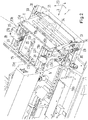
- Fig. 4 is shown a perspective view of a transport device to a personalization system of a document.
- the grippers 2a, 2b in the previously explained third actuating position.
- the third operating position is arranged in the region of a turntable 61.
- the personalization position 10 (see Fig. 1 ) is in this case arranged on the turntable 61, in particular on a longitudinal direction 3 (see, eg Fig. 2 A back and a right and a left side edge of the personalization position 10 are formed by a U-shaped document stop 16.
- the turntable 61 is located in the personalization position 10 document about an axis of rotation which is parallel to the longitudinal axis 3 (see Fig. 2 ), and about an axis of rotation which is parallel to the lateral axis 4, rotatable.
- a linear guide 19b of the second gripper 2b is shown, wherein a base plate 24b of the second gripper 2b in the longitudinal direction 3 and against the longitudinal direction 3 on the linear guide 19b is movable.
- a drive of the second gripper 2b is performed by the first stepping motor 31, wherein a rotation of an output shaft of the first stepping motor 31 via gears 32 and a toothed belt 33 is translated into a linear movement.
- Fig. 4 the flap 6 is shown in a closed state. It should be noted that the grippers 2a, 2b are in the third operating position 2a, 2b, whereby the flap 6 is automatically in the closed state.
- a lateral bending spring 17 can be seen, which serves for aligning a document to be personalized in the lateral direction 4.
- contact opposing blocks 62a, 62b of the grippers 2a, 2b are shown in detail in FIG Fig. 5 to be discribed.
- the feed surface 5 see, for example, FIG Fig. 1
- Guide slots 64a, 64b extending in the longitudinal direction 3, wherein a width of the guide slots 64a, 64b in the lateral direction 4 by a predetermined amount is greater than a width of the contact counter-blocks 62a, 62b.
- a vertically upper surface of the contact counter-blocks 62a, 62b is preferably arranged in the same plane as the surface of the feed surface 5, that is flush with the feed surface 5.
- the Document In the first part of the movement is the Document between the contact blocks 11a, 11b and the contact counter-blocks 62a, 62b frictionally held or clamped, wherein the contact blocks 11a, 11b and the contact counter-blocks 62a, 62b move simultaneously and to the same extent.
- Fig. 5 is a detailed perspective view of a drive system of a device 1 according to the invention (see, eg Fig. 1 ) for a drive in the vertical direction 20 shown.
- a second stepping motor 35 is shown, which is arranged in a lower region of the device 1 and whose output axis 39 is oriented in the vertical direction 20.
- the vertical output shaft 39 is coupled to a gear 36, which in turn interacts with a toothed belt 40.
- the toothed belt 40 is in this case deflected via further toothed wheels 36 and interacts with gripper-side toothed wheels 41a, 41b.
- gripper-side gears 41a, 41b gripper-side spindles 42a, 42b are synchronously rotated.
- gripper-side spindles 42a, 42b interact with gripper-side nuts 43a, 43b in each case.
- the gripper-side nut 43a, 43b are each mechanically connected to corresponding arm holders 23a, 23b of the grippers 2a, 2b, whereby upon rotation of the gripper-side spindles 42a, 42b, depending on the direction of rotation, a linear movement of the gripper-side nuts 43a, 43b and thus the gripper 2a, 2b takes place in or against the vertical direction 20.
- a linear guide of the gripper 2a, 2b may be provided in the vertical direction.
- a drive of the gripper 2a, 2b simultaneously, ie synchronously, and via screw drives, which are formed by the gripper side gears 41a, 41b, the gripper side spindles 42a, 42b and the gripper side nuts 43a, 43b.
- contact blocks 11a, 11b and contact counter blocks 62a, 62b of the grippers 2a, 2b are here by means of arm holders 63a, 63b on base plates 24a, 24b of the gripper 2a, 2b (see Fig. 4 and Fig. 7 ) attached.
- the contact blocks 11a, 11b are arranged in the vertical direction 20 over the contact opposing blocks 62a, 62b and are movable in the vertical direction 20.
- the contact counter-blocks 63a, 63b are not movable in the vertical direction, that is firmly connected to the base plate 24a, 24b.
- a contact surface of the contact counter-blocks 62a, 62b can have the same size as one on a lower side 44a (see FIG Fig. 6 ) arranged contact surfaces of the contact blocks 11a, 11b.
- the contact counter-blocks 62a, 62b are movable in and against the longitudinal positioning direction 3.
- the contact counter-blocks 62a, 62b are at the same time and to the same extent as those, ie synchronously with, the contact blocks 11a, 11b in or against the longitudinal positioning direction 3 movable.
- Fig. 6 is a perspective detailed view of a gripper 2a shown.
- a contact block 11a is resiliently arranged on a support arm 21a of the first gripper 2a. Between the support arm 21a and the contact block 11a, two mutually parallel spring elements 22a are arranged. Also shown is a contact surface, which is arranged on an underside 44a, viewed in the vertical direction 20, of the contact block 11a. This contact surface comes into mechanical contact with a document to be positioned when the gripper 2a is moved to an operating state.
- the springs 22a allow this compensation of different thicknesses or heights of documents to be transported.
- the gripper 2a is moved in each of the previously explained operating positions in the vertical direction 20 in a vertical position, wherein the distance to be set the bottom 44a of a feed surface 5 (see, eg Fig. 1 ) and / or a vertically upper surface of a contact counter block 62a (see, eg, FIG Fig. 4 ) is equal to.
- the movement of the grippers 2a, 2b in the vertical direction 20 in a transition from a release state to the actuation state can be the same, ie predetermined, for all documents to be transported.
- the contact block 11 a is displaced in the vertical direction 20 counter to spring forces which are generated by the spring elements 22 a.
- the spring forces thus serve to hold the document to be transported between contact blocks 11a, 11b and the contact counter blocks 62a, 62b parallel to the feed surface 5.
- a vertical distance between the bottom 44a and the feed surface 5 and / or in the vertical direction 20 upper surface of the contact counter block 62 a is provided.
- a front-side contact part 45a of the contact block 11a which forms a rear end side 14a of the contact block 11a in the longitudinal positioning direction 3.
- the contact part 45a is movably mounted in or against the longitudinal displacement direction 3 on the contact block 11a.
- the front-side contact part 45a via two springs 46a arranged in parallel, of which only one in Fig. 6 is shown, mounted on the contact block 11a.
- the storage takes place here via a slot element 47a, which at one in the longitudinal direction of the third rear end of the contact block 11 a is arranged.
- An elongated hole 48a of the oblong hole element 47a hereby extends an axis 49a, on which the frontal contact part 45a in the longitudinal positioning direction 3 is fastened behind the oblong hole 48a.
- the shaft 49a is fixed to a front end 50a of the contact block 11a.
- the contact block 11a has a double-T-shaped profile in a cross section with a sectional plane perpendicular to the longitudinal positioning direction 3.
- a rubber coating 51a is arranged, which improves the frictional engagement between gripper 2a and a document to be transported and thus facilitates non-positive transport of the document to be transported.
- a leaf spring 52a extending obliquely from a front end side of the contact block 11a into a space 53a formed by the upper and lower legs and the connecting bridge of the double T-shaped contact block 11a.
- the leaf spring 53a is in this case on a sleeve 54a, which is arranged around the axis 49a around, and presses the axis 49a against the vertical direction 20 down.
- the gripper 2a is e.g. in the first operating position in an operating state, so the front-side contact part 45a, the axis 49a, the spring 46a and the sleeve 54a is pushed upwards, ie in the vertical direction 20, against the spring force of the leaf spring 52a.
- the axis 49 a can be displaced in the slot 48 a in the vertical direction 20.
- the front-side contact part 45a in the further sub-process in the vertical direction 20 is arranged lower than in the first sub-process in which is ensured by the described training that the frontal contact portion 45a is arranged in the vertical direction 20 on or on the document to be transported.
- the front-side contact part 45a is arranged relative to the document to be transported, that a frontal contact surface 55a of the frontal contact portion 45a in the amount of a cover of a book, which the contact blocks 11a, 11b and the contact counter-blocks 62a, 62b contains document to be transported is positioned.
- a side view of the device 1 according to the invention is shown.
- a base plate 24a of a first gripper 2a is shown, which, as previously explained, is movable on a linear guide 19a in a longitudinal displacement direction 3 with a linear movement.
- a stop tongue 56a is attached on the base plate 24a.
- the stop tongue 56a extends in the vertical direction 20 of the base plate 24a upwards.
- the stop tongue 56a is in this case formed, for example, by a metal strip.
- the stop tongue 56a is formed as a leg of a rectangular mounting bracket 57a, wherein another leg of the mounting bracket 57a is screwed to the base plate 24a.
- a flap 6 of the device 1 also shown is a flap 6 of the device 1 and a rotation axis 7 of the flap 6. Furthermore, a stop tongue 58a corresponding to the stop tongue 58a of the flap 6 is shown. This corresponding stop tongue is in this case rotatably attached to the housing 37 about a rotation axis 59a.
- the corresponding stop tongue 58a is in this case mechanically coupled to the flap 6 such that a rotational movement of the corresponding stop tongue 58a about the rotation axis 59a causes the flap 6 to rotate about the rotation axis 7 of the flap 6 such that the flap 6 moves into an open state ,
- the corresponding stop tongue 58a is formed as an angled metal strip, for example. If the first gripper 2a moves out of the ready position of the first gripper 2a in the longitudinal displacement direction 3, then the stop tongue 56a is released from the corresponding stop tongue 58a.
- return spring elements which can be formed for example by appropriately arranged rotation springs, thus causing a reverse rotation of the corresponding stop tongue 58a and thus also closing the flap 6. This ensures advantageously by a mechanical coupling that the flap 6 only opens when the first gripper 2a moves to the standby position. This is especially the case whenever a document is fed or ejected, wherein in these states no personalization, eg by a laser irradiation, takes place.
- Fig. 7 can be seen the proximity switch 29 and the corresponding magnetic element 30.
- the magnetic element 30 is in this case attached to a free end of a holder 60, wherein the holder 60 is mechanically connected to the axis of rotation 7.
- the holder 60 also rotates so that the magnetic element 30 moves into a detection range of the proximity switch 29.
- the proximity switch 29 can detect that the flap 6 is in an opened state.
- a diaphragm of the laser can be controlled, wherein the aperture of the laser is closed in an open state of the flap 6.
Landscapes
- Engineering & Computer Science (AREA)
- Mechanical Engineering (AREA)
- Physics & Mathematics (AREA)
- Health & Medical Sciences (AREA)
- Electromagnetism (AREA)
- General Health & Medical Sciences (AREA)
- Toxicology (AREA)
- Manufacturing & Machinery (AREA)
- Registering Or Overturning Sheets (AREA)
- Sheets, Magazines, And Separation Thereof (AREA)
Description
- Die Erfindung betrifft eine Vorrichtung und ein Verfahren zur Positionierung eines Dokuments. Insbesondere betrifft die Erfindung eine Einzugsvorrichtung für eine Personalisierungsanlage zur Personalisierung eines Sicherheitsdokuments.
- Bei einer Personalisierung von Dokumenten, insbesondere von Sicherheitsdokumenten wie z. B. Personalausweisen oder Pässen, werden personalisierende und/oder individualisierende Informationen physikalisch in oder auf das Dokument ein- bzw. aufgebracht. Hierzu ist es erforderlich, ein zu personalisierendes Dokument in eine Personalisierungsposition zu positionieren, wobei die Personalisierungsposition eine Position bezeichnet, in welcher die vorhergehend erwähnten Informationen physikalisch in das Dokument eingebracht oder auf das Dokument aufgebracht werden.
- Bekannte Einzugsmechanismen bei sogenannten Passpersonalisierungsanlagen umfassen ein Reibrad und/oder einen Reibriemen zum Transport des Dokuments aus einer Einzugsposition in die Personalisierungsposition. So beschreibt die
DE 695 12 527 T2 eine Maschine, mit der ein Verfahren zur Fälschungssicherung, Echtheitserkennung oder Personalisierung von Papierbögen durchführbar ist. Die Maschine umfasst sogenannte Bogeneinzugsrollen zum Transport von zu personalisierenden Bögen. Ein derartiger Transport weist den Nachteil auf, dass Dokumente schief in der Personalisierungsposition positioniert werden oder ein Verknicken des Dokuments beim Einzug erfolgt. Ein schiefer Einzug kann zu Ausschuss, verschlechterter Personalisierungsqualität sowie zum Steckenbleiben des Dokuments in der Personalisierungsanlage führen. - Weiter bekannt sind Personalisierungsanlagen, die zum Einzug und Transport von Dokumenten Werkstückträger bzw. Kassetten oder mit der Anlage verbundene Rahmen umfassen. Derartige Mechanismen können zwar einen Schiefeinzug und ein Verklemmen der Dokumente verhindern, verursachen jedoch bei einem manuellen Einlegen von Dokumenten in die Personalisierungsanlage zusätzlichen Arbeitsaufwand.
- Die
US 2008/295722 A1 offenbart ein Plattenherstellungsverfahren umfassend eine Vor-Orientierungsbehandlung einer Druckplatte relativ zu einer Abbildungstrommel einer Plattenherstellungsmaschine während die Druckplatte entlang eines Plattenzufuhrpfades zur Plattenherstellungsmaschine bewegt wird. - Die
US 2007/145667 A1 offenbart ein Verfahren zur Korrektur der lateralen Position eines Druckmaterials. Dieses umfasst ein Greifen des Druckmaterials mit einer Transporteinheit, das Verdrehen der Transporteinheit in einem seitlichen Positionskorrekturwinkelbereich zur Korrektur der seitlichen Position des Druckmaterials, und das Verdrehen der Transporteinheit aus dem lateralen Positionskorrekturwinkelbereich unter Beibehaltung der Korrektur der seitlichen Position des Druckmaterials. - Die
EP 2 415 700 A2 offenbart eine Vorrichtung zur Ausrichtung eines flachen Produkts. Die Vorrichtung weist eine Ausrichtungseinheit, die über einer Förderfläche angeordnet ist. Die Ausrichtungseinheit so vorgesehen ist, dass auf eine Oberfläche transferierte Kraft die Position eines flachen Produkts relativ zur Förderfläche ändert. - Die
DE 199 56 712 A1 offenbart eine Haltevorrichtung zum Halten eines buchartigen Dokuments mit einer Vielzahl von Blättern während eines Druckvorgangs auf wenigstens einer Seite des buchartigen Dokuments. Die Haltevorrichtung weist eine Klemmeinrichtung auf, welche wenigstens ein Blatt des buchartigen Dokuments klemmt, wobei die Klemmeinrichtung drei Keile aufweist. - Es stellt sich das technische Problem, eine Vorrichtung und ein Verfahren zur Positionierung eines Dokuments, insbesondere zur Positionierung eines Sicherheitsdokuments in einer Personalisierungsanlage, zu schaffen, welche eine Genauigkeit der Positionierung erhöht, eine Beschädigung des Dokuments bei der Positionierung minimiert und eine Bedienbarkeit vereinfacht.
- Die Lösung des technischen Problems ergibt sich durch die Gegenstände mit den Merkmalen der Ansprüche 1 und 10. Weitere vorteilhafte Ausgestaltungen ergeben sich aus den Unteransprüchen.
- Vorgeschlagen wird eine Vorrichtung zur Positionierung eines Dokuments. Die Vorrichtung kann hierbei Teil einer sogenannten Personalisierungsanlage sein, wobei mittels der Personalisierungsanlage eine Personalisierung des Dokuments durchführbar ist. Hierbei umfasst eine Personalisierung z.B. das Erzeugen einer physikalischen Repräsentation von personalisierenden und/oder individualisierenden Informationen in oder auf dem Dokument. Eine personalisierende und/oder individualisierende Information bezeichnet hierbei eine Information, welche das Dokument eindeutig unterscheidbar von weiteren Dokumenten macht. Eine solche Information kann beispielsweise ein Lichtbild, ein Hologramm, eine Dokumentennummer, eine Seriennummer, ein Name eines Inhabers des Dokuments oder eine Unterschrift des Inhabers des Dokuments sein. Derartige Informationen können hierbei Sicherheitsmerkmale oder Sicherheitselemente darstellen. Auch weitere Ausbildungen solcher Informationen sind selbstverständlich vorstellbar.
- Insbesondere kann das Dokument durch eine Laser-Personalisierungsanlage oder eine Laser-Personalisierungsvorrichtung personalisiert werden. Hierbei wird ein Laserstrahl von einem Laser erzeugt und z.B. mittels Spiegeln derart auf das Dokument oder in das Dokument gestrahlt, dass in einer Schicht oder mehreren Schichten des Dokuments Änderungen der Dokumentenstruktur derart erfolgen, dass eine grafische, insbesondere sichtbare, Repräsentation von Informationen erzeugt wird.
- Die Laser-Personalisierungsanlage kann hierzu einen Laser, optische Umlenkmittel und eine entsprechende Steuereinrichtung für den Laser und die Umlenkeinrichtungen umfassen. Auch kann die Laser-Personalisierungsanlage einen Drehtisch umfassen, mit welchem eine Orientierung des Dokuments in der Personalisierungsposition veränderbar ist.
- In diesem Falle kann die vorgeschlagene Vorrichtung zur Positionierung eines Dokuments aus einer Ausgangsposition in eine Personalisierungsposition dienen, insbesondere zum Einzug des Dokuments aus einer Ausgangsposition in die Personalisierungsposition. Die Personalisierungsposition bezeichnet hierbei eine vorbestimmte Position, in welcher das Dokument mit einer bekannten Position und Ausrichtung zu einem oder mehreren Personalisierungsmitteln positioniert ist. Befindet sich also das Dokument in der Personalisierungsposition, so ist eine Position und/oder Ausrichtung des Dokuments bezüglich eines globalen Koordinatensystems bekannt. Es ist auch möglich, dass in der Personalisierungsposition ein Positionsbereich und/oder Orientierungsbereich des Dokuments bekannt ist, wobei durch die Positionierung in der Personalisierungsposition sichergestellt ist, dass sich das Dokument an einer Position aus dem Positionsbereich befindet und/oder eine Ausrichtung aus dem Ausrichtungsbereich aufweist. Die Personalisierungsposition dient somit zum Positionieren des Dokuments in einer gewünschten Position und/oder mit einer gewünschten Ausrichtung zu einem Personalisierungsmittel, z. B. zu dem vorhergehend beschriebenen Laser zur Laserpersonalisierung.
- Die Vorrichtung umfasst mindestens ein bewegbares Positionierungsmittel. Weiter weist die Vorrichtung eine Einzugsfläche auf. Die Einzugsfläche dient zum Auflegen des zu personalisierenden Dokuments. Weiter kann die Vorrichtung ein Gehäuse umfassen, welches z. B. ein Teil eines Gehäuses der Personalisierungsanlage ist, welche die vorgeschlagene Vorrichtung umfasst. Das bewegbare Positionierungsmittel ist hierbei relativ zu der ortsfesten Einzugsfläche bewegbar.
- In einem Positioniervorgang wird das zu personalisierende Dokument durch das bewegbare Positionierungsmittel entlang der Einzugsfläche von einer Ausgangs- oder Einzugsposition des Dokuments in die Personalisierungsposition bewegt. Das mindestens eine Positionierungsmittel ist derart bewegbar, dass durch das Positionierungsmittel in einem ersten Teilvorgang des Positioniervorganges eine zur Einzugsfläche normale Kraft, die auch als Andrückkraft bezeichnet werden kann, und eine zur Einzugsfläche parallele Verschiebekraft auf ein auf die Einzugsfläche aufgelegtes Dokument derart ausübbar ist, dass das auf die Einzugsfläche aufgelegte Dokument um einen ersten vorbestimmten Verschiebeweg in eine longitudinale Positionierrichtung verschiebbar ist. In dem ersten Teilvorgang wird eine reibschlüssige Verbindung zwischen dem Dokument und dem Positionierungsmittel hergestellt. Die reibschlüssige Verbindung wird hierbei durch die zur Einzugsfläche normale Kraft, die durch das Positionierungsmittel auf das Dokument ausgeübt wird, hergestellt. Gleichzeitig zur Erzeugung und Ausübung der zur Einzugsfläche normalen Kraft wird durch das Positionierungsmittel die zur Einzugsfläche parallele Verschiebekraft auf das auf die Einzugsfläche aufgelegte Dokument ausgeübt. Die zur Einzugsfläche parallele Verschiebekraft kann hierbei in die vorhergehend erwähnte longitudinale Positionierrichtung orientiert sein oder zumindest einen Anteil aufweisen, der in diese Richtung orientiert ist. Im ersten Teilvorgang erfolgt ein reibschlüssiger Transport des Dokuments. Das Dokument wird somit über die Einzugsfläche in die longitudinale Positionierrichtung transportiert oder verrutscht. Hierbei kann das Dokument durch das Positionierungsmittel an ein bewegliches Mittel zur Erzeugung einer Gegenkraft und nicht an die ortsfeste Einzugsfläche angepresst werden, wobei das bewegliche Mittel Teil des Positionierungsmittels ist und sich mit diesem bewegt. Hierdurch wird die Gefahr eines Zerkratzens aufgrund des Transports entlang der Einzugsfläche verringert. Am Ende des ersten Teilvorgangs wird das Dokument in einer Zwischenposition positioniert, die nicht der Personalisierungsposition entspricht. Der erste vorbestimmte Verschiebeweg ist somit nur ein Teil des erforderlichen vollständigen Verschiebewegs.
- Die longitudinale Positionierrichtung bezeichnet hierbei eine Hauptrichtung der Positionierung, die parallel zur Einzugsfläche orientiert ist. Folgend bezeichnet eine laterale Richtung eine Richtung, die ebenfalls parallel zur Einzugsfläche orientiert ist und einen Winkel von 90° mit der longitudinalen Positionierrichtung einschließt. Eine vertikale Richtung bezeichnet eine Richtung, die senkrecht zur Einzugsfläche und senkrecht zur longitudinalen Positionierrichtung und lateralen Richtung orientiert ist.
- Erfindungsgemäß ist das mindestens eine Positionierungsmittel in einem weiteren Teilvorgang der Positionierung derart bewegbar, dass durch das Positionierungsmittel eine zu der Einzugsfläche parallele Verschiebekraft auf das auf die Einzugsfläche aufgelegte Dokument derart ausübbar ist, dass das auf die Einzugsfläche aufgelegte Dokument um einen weiteren vorbestimmten Verschiebeweg in eine weitere vorbestimmte Positionierrichtung verschiebbar ist. Die weitere vorbestimmte Positionierrichtung ist vorzugsweise die longitudinale Positionierrichtung. An einem Ende des weiteren Teilvorgangs wird das Dokument in der Personalisierungsposition positioniert. Z.B. kann das Dokument am Ende des weiteren Teilvorgangs an einem Dokumentenanschlag anstoßen, wobei ein an dem Dokumentenanschlag anliegendes Dokument sich in der Personalisierungsposition befindet.
- Der erste vorbestimmte Verschiebeweg und der weitere vorbestimmte Verschiebeweg können somit den gewünschten vollständigen Verschiebeweg ergeben. In dem weiteren Teilvorgang wird das Dokument aus der vorhergehend erwähnten Zwischenposition in die Personalisierungsposition transportiert. Der Dokumentenanschlag kann hierbei Teil der vorgeschlagenen Vorrichtung oder Teil der Personalisierungsanlage sein und kann z. B. als mechanischer Anschlag, insbesondere L- oder U-förmiger Anschlag ausgebildet sein.
- In dem weiteren Teilvorgang ist das mindestens eine Positionierungsmittel derart bewegbar, dass durch das Positionierungsmittel während des weiteren Teilvorgangs keine zur Einzugsfläche normale Kraft auf das auf die Einzugsfläche aufgelegte Dokument ausgeübt wird. Somit erfolgt im weiteren Teilvorgang keine reibschlüssige Verbindung von Positionierungsmittel und Dokument und somit auch kein reibschlüssiger Transport des Dokuments. Insbesondere kann die im weiteren Teilvorgang durch das Positionierungsmittel ausgeübte Verschiebekraft eine Druckkraft sein, durch welche das Dokument in die weitere vorbestimmte Positionierrichtung geschoben wird. Beispielsweise kann das mindestens eine Positionierungsmittel derart bewegbar sein, dass die Verschiebekraft auf einen Rand oder eine Seitenfläche des auf die Einzugsfläche aufgelegten Dokuments oder auf einen Rand oder eine Seitenfläche eines Einbandes eines Buches, welches das zu personalisierende Dokument umfasst, ausgeübt wird. Der Rand oder die Seitenfläche bezeichnen hierbei eine Fläche, die senkrecht zur Einzugsfläche orientiert sein kann. Der Rand oder die Seitenfläche unterscheidet sich in diesem Fall von einer Oberfläche des zu personalisierenden Dokuments.
- Die vorgeschlagene Vorrichtung reduziert hierbei in vorteilhafter Weise die Gefahr, dass das zu personalisierende Dokument während des Positioniervorgangs schief, also mit einer unerwünschten Abweichung, in der Personalisierungsposition positioniert wird. Dies beruht u.a. darauf, dass im weiteren Teilvorgang keine zur Einzugsfläche normale Kraft mehr auf das zu positionierende Dokument ausgeübt wird. Eine solche Normalkraft verhindert insbesondere eine Bewegung des Dokuments in lateraler Richtung sowie Drehbewegungen des Dokuments, insbesondere auch um eine zur Einzugsfläche senkrechte Drehachse. Durch das Reduzieren der Normalkraft oder Andrückkraft auf Null werden die vorhergehend erwähnten Bewegungen freigegeben, sodass sich das Dokument während des weiteren Teilvorgangs, beispielsweise durch ein Zusammenwirken mit Führungsmitteln und/oder einem Dokumentanschlag, in einer gewünschten Weise ausrichten kann, wobei während des Ausrichtens beispielsweise eine laterale Bewegung des Dokuments und/oder eine Rotationsbewegung des Dokuments erfolgen kann.
- Weiter vereinfacht die vorgeschlagene Vorrichtung eine Bedienung, insbesondere ein Einlegen des zu personalisierenden Dokuments auf die Einzugsfläche. Da im ersten Teilvorgang das Positionierungsmittel nicht in longitudinaler Richtung vor dem zu transportierenden Dokument positioniert werden muss, um diese wie im weiteren Teilvorgang durch eine Druckkraft zu schieben, kann der Einzugsbereich weitestgehend frei von mechanischen Elementen gestaltet werden. Insbesondere wird somit auch eine Gefahr von Verletzungen eines Bedieners reduziert, da das Positionierungsmittel vollständig innerhalb eines Gehäuses der vorgeschlagenen Vorrichtung oder einer die vorgeschlagene Vorrichtung umfassenden Personalisierungsvorrichtung angeordnet sein kann, wobei ein Benutzer das Dokument von außen in das Gehäuse einführen kann.
- Die Vorrichtung kann hierbei weiterhin Führungsmittel oder -elemente, insbesondere Anschlagelemente, für das Dokument aufweisen, die insbesondere während des weiteren Teilvorgangs, eine Bewegung des Dokuments führen.
- In einer weiteren Ausführungsform ist das mindestens eine Positionierungsmittel mit zwei translatorischen Freiheitsgraden bewegbar. Insbesondere kann das mindestens eine Positionierungsmittel ausschließlich mit zwei translatorischen Freiheitsgraden bewegbar sein. Diese translatorischen Freiheitsgrade können hierbei eine Bewegung des Positionierungsmittels in der longitudinalen Positionierrichtung und in der vorhergehend erläuterten vertikalen Richtung ermöglichen. Eine Bewegung des Positionierungsmittels kann hierbei eine Linearbewegung sein. Insbesondere kann die Bewegung in oder entgegen der longitudinalen Positionierrichtung eine Linearbewegung und die Bewegung in oder entgegen der vertikalen Richtung eine Linearbewegung sein. Hierzu kann die Vorrichtung Führungselemente zur Führung der Bewegung Positionierungsmittels in den vorhergehend erwähnten Bewegungsrichtungen umfassen. Derartige Führungsmittel können beispielsweise Linearlager sein.
- Weiter kann die Vorrichtung Antriebsmittel zur Bewegung des Positionierungsmittels entlang der vorhergehend erwähnten Bewegungsrichtungen umfassen. So kann die Vorrichtung beispielsweise einen Linearmotor umfassen. Auch kann die Vorrichtung einen Rotationsmotor, beispielsweise einen Servo- oder Schrittmotor, umfassen sowie ein Getriebe zur Umsetzung der Rotations- in eine Linearbewegung. Ein solches Getriebe kann beispielsweise ein Zahnrad und einen mit dem Zahnrad zusammenwirkenden Zahnriemen umfassen.
- Durch eine Reduktion der Bewegungsfreiheitsgrade des Positionierungsmittels auf zwei Freiheitsgrade ergibt sich in vorteilhafter Weise eine möglichst einfache Ausbildung von Antriebs- und Führungselementen des Positionierungsmittels. Hierdurch können insbesondere ein für diese Antriebsmittel erforderlicher Bauraum sowie Herstellungskosten reduziert werden. Auch kann eine Ansteuerung der Antriebselemente vereinfacht werden.
- Selbstverständlich kann die Vorrichtung erste Antriebsmittel oder -elemente, die ausschließlich zur Bewegung des mindestens einen Positionierungsmittels in oder entgegen der longitudinalen Verschieberichtung dienen, und weitere Antriebsmittel umfassen, die ausschließlich einer Bewegung des mindestens einen Personalisierungsmittels in oder entgegen der vertikalen Richtung dienen.
- In einer weiteren Ausführungsform ist das Positionierungsmittel als Greifer ausgebildet, wobei der Greifer mindestens ein Kontaktelement aufweist, wobei das Kontaktelement eine erste und mindestens eine weitere Kontaktfläche aufweist. Die erste Kontaktfläche kann während des ersten Teilvorgangs des Positioniervorgangs mit dem zu positionierenden Dokument in mechanischem Kontakt sein. Insbesondere kann über die erste Kontaktfläche die vorhergehend erläuterte Andrückkraft und gleichzeitig die zur Einzugsfläche parallele Verschiebekraft auf das Dokument ausgeübt werden.
- Der Greifer kann auch ein Kontaktgegenelement aufweisen, wobei das zu positionierende Dokument durch das Kontaktelement an das Kontaktgegenelement, insbesondere eine Oberfläche des Kontaktgegenelements, angepresst oder angedrückt werden kann. Die Oberfläche des Kontaktgegenelements kann hierbei bündig zur Oberfläche der Einzugsfläche sein.
- Während des weiteren Teilvorgangs kann die weitere Kontaktfläche in mechanischem Kontakt mit dem zu positionierenden Dokument oder einem Einband eines Buches, welches das zu personalisierende Dokument umfasst, sein. Somit wird die im weiteren Teilvorgang wirkende Kraft, die parallel zur Einzugsfläche orientiert ist, mittels der weiteren Kontaktfläche übertragen. Das Kontaktelement kann beispielsweise block- oder quaderförmig ausgebildet sein, wobei die erste Kontaktfläche durch eine Oberfläche einer Unterseite des Kontaktelements und die weitere Kontaktfläche durch eine in der longitudinalen Positionierrichtung hintere Stirnfläche des Kontaktelements gebildet werden kann. Auch ist möglich, dass das Kontaktelement mehrere Teilelemente umfasst, wobei ein erstes Teilelement die erste Kontaktfläche und ein weiteres Teilelement die weitere Kontaktfläche aufweist oder ausbildet. Die einzelnen Teilelemente können hierbei mechanisch miteinander verbunden sein.
- Durch die Ausbildung des Positionierungsmittels als Greifer, der gleichzeitig die erste und die weitere Kontaktfläche aufweist, ergibt sich in vorteilhafter Weise eine einfache und platzsparende Ausbildung des Positionierungsmittels.
- In einer weiteren Ausführungsform ist der Greifer derart ausgebildet, dass ein die erste Kontaktfläche aufweisender Teil des Kontaktelements in einer zur Einzugsfläche normalen Richtung federnd gelagert ist und/oder ein die weitere Kontaktfläche aufweisender oder ausbildender Teil des Kontaktelements in longitudinaler Positionierrichtung federnd gelagert ist. Der Greifer kann beispielsweise einen Tragarm aufweisen, der z.B. L-förmig ausgebildet ist. Das Kontaktelement, insbesondere ein block- oder quaderförmiges Kontaktelement, kann an einem freien Ende des Tragarms des Greifers in vertikaler Richtung federnd gelagert sein. Alternativ oder kumulativ kann das Kontaktelement ein als Kopfteil ausgebildetes Teilelement aufweisen, wobei das Kopfteil die weitere Kontaktfläche aufweist oder ausbildet und an dem federnd gelagerten Kontaktblock oder -element in longitudinaler Richtung federnd gelagert ist.
- Durch die federnde Lagerung des Kontaktelements in einer zur Einzugsfläche normalen Richtung kann in vorteilhafter Weise eine variierende Dicke oder Höhe eines zu transportierenden Dokuments kompensiert werden. Insbesondere können Dokumente mit verschiedenen Dicken oder Höhen transportiert werden. Je dicker bzw. höher das zu transportierende Dokument, desto größer eine Auslenkung des Kontaktelements in der zur Einzugsfläche normalen Richtung und desto stärker die zur Einzugsfläche normale Kraft, die das zu transportierende Dokument im ersten Teilvorgang an die Einzugsfläche oder an eine Oberfläche des vorhergehend erläuterten Kontaktgegenelements andrückt oder anpresst. Entsprechend kann durch die federnde Lagerung des die weitere Kontaktfläche aufweisenden Teils eine variierende Länge des zu positionierenden Dokuments kompensiert werden, beispielsweise eine aufgrund von Fertigungstoleranzen variierende Länge. Eine Länge bezeichnet hierbei eine Länge des zu positionierenden Dokuments oder eines Einbands eines Buches, welches das zu positionierende Dokument umfasst, in der longitudinalen Positionierrichtung.
- In einer bevorzugten Ausführungsform umfasst die Vorrichtung zwei Positionierungsmittel, die im ersten sowie im weiteren Teilvorgang jeweils eine Kraft auf eine linke bzw. eine rechte Hälfte des zu positionierenden Dokuments ausüben. Hierbei kann die Vorrichtung derart ausgebildet sein, dass sich die zwei Positionierungsmittel synchron, also zeitgleich und im gleichen Maße bewegen. Wird z.B. im ersten Teilvorgang das zu positionierende Dokument schief eingezogen, so kann z.B. im weiteren Teilvorgang eine rechte Hälfte des zu positionierenden Dokuments während des Schiebevorgangs zeitlich vor einer linken Hälfte des Dokuments an einem Dokumentenanschlag anschlagen. In diesem Fall ist noch eine weitere Verschiebung der linken Hälfte des Dokuments notwendig, um auch die linke Hälfte vollständig an dem Dokumentenanschlag anschlagen zu lassen. Ist keine individuelle Bewegungssteuerung der Bewegung der Positionierungsmittel vorgesehen, bewegen sich also die beiden Positionierungsmittel synchron, so wird sich, während einer andauernden Bewegung des die linke Hälfte des Dokuments transportierenden Positionierungsmittels in die longitudinale Positionierrichtung, das die weitere Kontaktfläche aufweisende Teil des die rechte Hälfte des Dokuments transportierenden Positionierungsmittels entgegen der federnden Lagerung verschieben. Somit kann durch die federnde Lagerung in vorteilhafter Weise erreicht werden, dass auch bei einem im ersten Teilvorgang schiefen Einzug eine genaue Ausrichtung des zu positionierenden Dokuments in der Personalisierungsposition erfolgen kann.
- In einer weiteren Ausführungsform ist das Positionierungsmittel in der longitudinalen Positionierrichtung mindestens in eine erste Betätigungsposition, eine erste Freigabeposition, eine zweite Betätigungsposition und eine zweite Freigabeposition bewegbar. Die longitudinale Positionierrichtung ist hierbei eine horizontale Richtung. Hierbei ist das Positionierungsmittel in der vertikalen Richtung in der ersten Betätigungsposition von einem Freigabezustand in einen Betätigungszustand bewegbar.
- Eine Bewegung von dem Freigabezustand in den Betätigungszustand bezeichnet hierbei eine Bewegung in vertikaler Richtung. In dem Freigabezustand ist das Positionierungsmittel hierbei derart positioniert, dass keine Kraft auf das auf die Einzugsfläche aufgelegte Dokument ausgeübt wird. Insbesondere steht das Positionierungsmittels nicht in einem mechanischen Kontakt mit dem zu positionierenden Dokument. Beispielsweise kann sich das Positionierungsmittel, insbesondere das Kontaktelement des Positionierungsmittels, in dem Freigabezustand mit einem vorbestimmten vertikalen Abstand über der Einzugsfläche und/oder über der Oberfläche des Kontaktgegenelements befinden. Entsprechend steht das Positionierungsmittel, insbesondere das Kontaktelement des Positionierungsmittels, in dem Betätigungszustand der ersten Betätigungsposition in mechanischem Kontakt mit dem zu positionierenden Dokument, insbesondere einer Oberfläche des zu positionierenden Dokuments. Hierbei übt das Positionierungsmittel die Andrückkraft auf das zu positionierende Dokument aus. Wird das Positionierungsmittel in dem Betätigungszustand in der longitudinalen Positionierrichtung bewegt, so übt es gleichzeitig die zur Einzugsfläche parallele Verschiebekraft auf das zu positionierende Dokument aus. Die Normalkraft kann hierbei vollständig oder zumindest teilweise von einer Federkraft erzeugt werden, die durch die vorhergehend erläuterte gefederte Lagerung des Kontaktelements erzeugt wird. Auch in der Betätigungsposition kann sich das Positionierungsmittel, insbesondere das Kontaktelement des Positionierungsmittels, in einem vorbestimmten vertikalen Abstand über der Einzugsfläche und/oder über der Oberfläche des Kontaktgegenelements befinden, wobei der vertikale Abstand in dem Betätigungszustand kleiner ist als im Freigabezustand. Der einzustellende vertikale Abstand im Betätigungszustand kann insbesondere gleich, vorzugsweise jedoch kleiner, als eine minimale Dicke oder Höhe eines zu positionierenden Dokuments, jedoch größer als Null, gewählt werden. Der einzustellende vertikale Abstand im Freigabezustand kann insbesondere größer als eine maximale Dicke oder Höhe eines zu positionierenden Dokuments gewählt werden.
- Durch eine Bewegung von dem Freigabezustand in den Betätigungszustand wird das zu positionierende Dokument im ersten Teilvorgang gegriffen. Während des ersten Teilvorgangs befindet sich das Positionierungsmittel im Betätigungszustand und kann in der longitudinalen Verschieberichtung in die erste Freigabeposition bewegt werden. In der ersten Freigabeposition kann das Positionierungsmittel von dem Betätigungszustand in einen Freigabezustand bewegt werden. In diesem Freigabezustand in der ersten Freigabeposition ist das Positionierungsmittel in die zweite Betätigungsposition bewegbar.
- Beispielsweise kann das Positionierungsmittel entgegen der longitudinalen Verschieberichtung um eine vorbestimmte Strecke verschoben werden. Weiter kann das Positionierungsmittel in der zweiten Betätigungsposition von dem Freigabezustand in einen weiteren Betätigungszustand bewegbar sein. In diesem Betätigungszustand ist das Positionierungsmittel von der zweiten Betätigungsposition in die zweite Freigabeposition bewegbar. Beispielsweise kann das Positionierungsmittel in der longitudinalen Verschieberichtung von der zweiten Betätigungsposition in die zweite Freigabeposition bewegt werden. In der zweiten Freigabeposition ist das Positionierungsmittel von dem weiteren Betätigungszustand in einen Freigabezustand bewegbar, der z.B. gleich dem Freigabezustand in der ersten Betätigungsposition sein kann.
- Weiter ist möglich, dass das Positionierungsmittel von der zweiten Freigabeposition in eine dritte Betätigungsposition bewegbar ist, wobei das Positionierungsmittel in der dritten Betätigungsposition von einem Freigabezustand in einen Betätigungszustand bewegbar ist. Weiter kann das Positionierungsmittel von der dritten Betätigungsposition in dem Betätigungszustand in eine dritte Freigabeposition bewegt werden. Diese Bewegung kann beispielsweise entgegen der longitudinalen Verschieberichtung gerichtet sein. In der dritten Freigabeposition kann das Positionierungsmittel von dem Betätigungszustand in einen Freigabezustand bewegbar sein. Hierdurch ist es möglich, das Dokument durch einen reibschlüssigen Transport von der Personalisierungsposition in eine Auswurfposition zu transportieren, beispielsweise nach einer erfolgten Personalisierung.
- Der von dem Positioniermittel einzustellende vertikale Abstand zur Einzugsfläche und/oder des Kontaktelements zur Oberfläche des Kontaktgegenelements kann hierbei in den Freigabezuständen aller Positionen gleich sein. Auch kann der einzustellende vertikale Abstand zur Einzugsfläche und/oder zur Oberfläche des Kontaktgegenelements in den Betätigungszuständen aller Positionen gleich sein. Es ist jedoch auch möglich, dass der vertikale Abstand in dem Betätigungszustand der zweiten Betätigungsposition kleiner als der vertikale Abstand in dem Betätigungszustand der ersten Betätigungsposition und der dritten Betätigungsposition ist.
- Auch kann das Positionierungsmittel in eine Ausgangsposition bewegbar sein, wobei das Positionierungsmittel von der Ausgangsposition in die erste Betätigungsposition bewegbar ist. Die Ausgangsposition kann beispielsweise in longitudinaler Richtung hinter der Auswurfposition angeordnet sein.
- In einer weiteren Ausführungsform umfasst die Vorrichtung eine Klappe, wobei die Klappe an einem in der longitudinalen Positionierungsrichtung vorderen Ende der Einzugsfläche angeordnet ist. In einem geöffneten Zustand gibt die Klappe die Einzugsfläche frei. In einem geschlossenen Zustand sperrt die Klappe die Einzugsfläche.
- Die Klappe kann in eine Außenwand eines Gehäuses der vorgeschlagenen Vorrichtung oder eines Gehäuses einer Personalisierungsvorrichtung integriert sein. Beispielsweise kann die Klappe in einem geschlossenen Zustand einen Innenraum des Gehäuses nach außen hin verschließen. Somit kann in einem geschlossenen Zustand der Klappe kein Dokument in das Gehäuse eingeführt werden. In einem geöffneten Zustand ist eine Einführung oder ein Einlegen zumindest eines Teils des zu personalisierenden Dokuments in das Gehäuse und auf die Einzugsfläche möglich.
- Insbesondere kann die Klappe in einem geöffneten Zustand einen Teil, insbesondere einen in der longitudinalen Positionierrichtung vorderen Teil, der Einzugsfläche ausbilden. Hierbei kann die Klappe in dem geöffneten Zustand aus der Gehäusewand herausragen. Hierdurch wird in vorteilhafter Weise ein Auflegen des Dokuments auf die Einzugsfläche und auch ein Einschieben des Dokuments in z.B. eine vorbestimmte Einzugsposition, aus welcher das Dokument nachfolgend durch das mindestens eine Positionierungsmittel in die Personalisierungsposition transportiert wird, vereinfacht werden.
- In einer weiteren Ausführungsform ist das Positionierungsmittel in der longitudinalen Positionierungsrichtung in eine Bereitschaftsposition bewegbar. Diese Bereitschaftsposition kann hierbei gleich der vorhergehend erläuterten dritten Freigabeposition sein. Weiter ist die Vorrichtung derart ausgebildet, dass die Klappe sich öffnet, wenn sich das Positionierungsmittel in die Bereitschaftsposition bewegt und sich die Klappe schließt, wenn sich das Positionierungsmittel aus der Bereitschaftsposition heraus bewegt. Weiter kann die Vorrichtung derart ausgebildet sein, dass die Klappe ausschließlich dann geöffnet ist oder in einen geöffneten Zustand versetzbar ist, wenn sich das Positionierungsmittel in der Bereitschaftsposition befindet. In der Bereitschaftsposition kann sich ein zu transportierendes Dokument in einer Einzugs-Auswurf-Position befinden, was nachfolgend näher erläutert wird.
- Beispielsweise kann die Vorrichtung mindestens eine Einrichtung zur Erfassung einer Position, insbesondere einer longitudinalen Position, des Positionierungsmittels umfassen. Diese Einrichtung kann beispielsweise signal- oder datentechnisch mit einer Einrichtung zur Freigabe einer Klappenbewegung, beispielsweise mit einer Verriegeleinrichtung, verbunden sein. Hierbei kann das Öffnen der Klappe durch die Einrichtung zur Freigabe ausschließlich dann erfolgen oder dann freigegeben werden, wenn die Einrichtung zur Erfassung einer Position des Positionierungsmittels ein entsprechendes Ausgangssignal erzeugt.
- Selbstverständlich ist auch vorstellbar, dass die Einrichtung zur Erfassung einer Position des Positionierungsmittels daten- oder signaltechnisch mit einer Einrichtung zur Verstellung der Klappe gekoppelt ist. Hierbei kann die Klappe z.B. durch die Einrichtung zur Verstellung, beispielsweise eine motorisch betriebene Einrichtung zur Verstellung, immer dann geöffnet werden, wenn sich das Positionierungsmittel in die Bereitschaftsposition bewegt oder sich in dieser Position befindet.
- Auch möglich ist, dass das Positionierungsmittel und eine Einrichtung zur Verstellung der Klappe mechanisch koppelbar sind. Hierbei kann z.B. das Positionierungsmittel ein mechanisches Koppelelement, beispielsweise eine Anschlagzunge, aufweisen, wobei die Einrichtung zur Verstellung ein korrespondierendes Koppelelement, beispielsweise eine korrespondierende Anschlagzunge, ausbildet. Bewegt sich das Positionierungsmittel in die Bereitschaftsposition, so kann das Koppelelement des Positionierungsmittels mit dem korrespondierenden Koppelelement der Einrichtung zur Verstellung wechselwirken, wodurch ein Öffnen der Klappe bewirkt wird. Weiter kann die Einrichtung zur Verstellung der Klappe ein Rückstellelement umfassen, welches ein Schließen der Klappe bewirkt, wenn das Positionierungsmittel aus der Bereitschaftsposition wegbewegt wird und die Koppelelemente nicht mehr in mechanischem Kontakt stehen.
- Selbstverständlich ist auch jede andere Art einer mechanischen Kopplung, beispielsweise eine dauerhafte mechanische Kopplung, zwischen dem Positionierungsmittel und der Einrichtung zur Verstellung der Klappe vorstellbar. Die Einrichtung zur Verstellung der Klappe kann beispielsweise eine lineare Bewegung des Koppelelements in eine rotatorische Bewegung der Klappe umwandeln.
- Hierdurch ergibt sich in vorteilhafter Weise, dass die Klappe nur dann geöffnet wird bzw. in einen geöffneten Zustand versetzbar ist, wenn sich das Positionierungsmittel in der Bereitschaftsposition befindet, wobei die Bereitschaftsposition nicht gleich der zweiten Freigabeposition ist. In diesem Fall ist es nämlich nicht möglich, dass ein Benutzer in einen Innenraum des Gehäuses hineingreift, wenn sich das Positionierungsmittel nicht in der Bereitschaftsposition befindet. Auch ist es, z.B. im Falle einer Lasergravur, nicht möglich, dass Laserstrahlen aus dem Gehäuse heraustreten und in ein Auge des Benutzers gelangen können.
- In einer weiteren Ausführungsform umfasst die Vorrichtung mindestens ein Mittel zur Erfassung eines Schließzustandes der Klappe, wobei eine Lasereinrichtung nur dann freigegeben wird, wenn die Klappe geschlossen ist. Freigegeben bedeutet hierbei, dass ein Laserstrahl nur dann erzeugbar ist und/oder auf das Dokument gestrahlt werden kann, wenn die Klappe geschlossen ist. So kann z.B. eine Blende einer Lasereinrichtung nur dann geöffnet ist oder in einen geöffneten Zustand versetzbar ist, wenn die Klappe geschlossen ist. Dies stellt eine zusätzliche Sicherheitsmaßnahme dar. Befindet sich die Klappe in einem geöffneten Zustand, so ist eine Blende der Lasereinrichtung geschlossen. Somit ist sichergestellt, dass kein Laserlicht in unbeabsichtigter Weise in ein Auge eines Benutzers gelangen kann. Selbstverständlich kann die Lasereinrichtung auch elektronisch gesperrt oder freigegeben werden, wobei in Abhängigkeit eines Zustands der Klappe ein Freigabe- oder Sperrsignal für die Lasereinrichtung erzeugt wird.
- Das Mittel zur Erfassung eines Schließzustandes der Klappe kann beispielsweise als Einrichtung zur Erfassung einer Winkelposition der Klappe ausgebildet sein. Auch kann das Mittel zur Erfassung eines Schließzustandes als optischer, induktiver, magnetischer oder kapazitiver oder weiterer Sensor ausgebildet sein. Ein Ausgangssignal des Sensors kann z.B. ausschließlich zwei Zustände repräsentieren, wobei die Klappe in einem ersten Zustand beispielsweise geschlossen und in einem weiteren Zustand geöffnet ist.
- In einer weiteren Ausführungsform umfasst die Vorrichtung mindestens ein Mittel zum lateralen Ausrichten. Das laterale Ausrichten beschreibt hierbei eine Bewegung des zu personalisierenden Dokuments in einer lateralen Richtung, die senkrecht zur longitudinalen Positionierrichtung orientiert ist. Das Mittel zum lateralen Ausrichten derart ausgebildet und/oder angeordnet ist, dass eine laterale Verschiebekraft auf das auf die Einzugsfläche aufgelegte Dokument derart ausübbar ist, dass es in einer Richtung senkrecht zu der longitudinalen Positionierrichtung, insbesondere in der lateralen Richtung, verschiebbar ist. Insbesondere kann das Mittel zum lateralen Ausrichten derart ausgebildet und/oder angeordnet sein, dass das auf die Einzugsfläche aufgelegte Dokument nach einem Ende des ersten Teilvorgangs, also zu Beginn oder während des weiteren Teilvorgangs, senkrecht zu der longitudinalen Positionierrichtung, insbesondere in der lateralen Richtung, verschiebbar ist. Beispielsweise kann das Mittel zum lateralen Ausrichten als Feder, insbesondere als Blattfeder, ausgerichtet sein, wobei die Blattfeder aus einer Ausgangsstellung ausgelenkt wird, wenn das zu positionierende Dokument während z.B. des ersten Teilvorgangs mit einem unerwünschten lateralen Versatz in die Zwischenposition bzw. während des weiteren Teilvorgangs in die Personalisierungsposition bewegt wird. Die Blattfeder kann z.B. durch einen Biegestreifen gebildet sein. Wird das Federelement aus der Ausgangs- oder Ruheposition ausgelenkt, so übt es eine Federkraft in lateraler Richtung auf das transportierte Dokument aus, wodurch dieses in lateraler Richtung bewegt wird.
- Weiter vorgeschlagen wird ein Verfahren zur Positionierung eines Dokuments. Hierbei wird ein Positionierungsmittel in einem ersten Teilvorgang derart bewegt, dass das Positionierungsmittel auf ein auf eine Einzugsfläche aufgelegtes Dokument eine zur Einzugsfläche normale Kraft und eine zur Einzugsfläche parallele Verschiebekraft derart ausübt, dass das auf die Einzugsfläche aufgelegte Dokument um einen ersten vorbestimmten Verschiebeweg in eine longitudinale Positionierrichtung verschoben wird. Weiter wird das Positionierungsmittel in einem weiteren Teilvorgang derart bewegt, dass das Positionierungsmittel auf das auf die Einzugsfläche aufgelegte Dokument eine zur Einzugsfläche parallele Verschiebekraft derart ausübt, dass das auf die Einzugsfläche aufgelegte Dokument um einen weiteren vorbestimmten Verschiebeweg in eine weitere vorbestimmte Verschieberichtung, die beispielsweise gleich der longitudinalen Positionierrichtung sein kann, verschoben wird. Hierbei kann insbesondere in dem weiteren Teilvorgang durch das Positionierungsmittel keine zur Einzugsfläche normale Kraft auf das auf die Einzugsfläche aufgelegte Dokument ausgeübt werden.
- Hierdurch ergibt sich in vorteilhafter Weise ein Verfahren, welches einen Dokumenteneinzug in insbesondere eine Personalisierungsvorrichtung ermöglicht, wobei die Gefahr eines schiefen Einzugs reduziert und eine Handhabbarkeit einer entsprechenden Vorrichtung vereinfacht wird.
- Die Erfindung wird anhand eines Ausführungsbeispiels näher erläutert. Die Figuren zeigen:
- Fig. 1
- eine schematische Draufsicht auf eine erfindungsgemäße Vorrichtung,
- Fig. 2
- eine perspektivische Ansicht einer erfindungsgemäßen Vorrichtung,
- Fig. 3
- eine Vorderansicht der in
Fig. 2 dargestellten Vorrichtung, - Fig. 4
- eine perspektivische Ansicht einer Personalisierungsanlage,
- Fig. 5
- eine Detailansicht einer Antriebsvorrichtung von Greifern,
- Fig. 6
- eine Detailansicht eines Greifers und
- Fig. 7
- eine Seitenansicht einer erfindungsgemäßen Vorrichtung.
- Nachfolgend bezeichnen gleiche Bezugszeichen Elemente mit gleichen oder ähnlichen technischen Merkmalen.
- In
Fig. 1 ist eine schematische Draufsicht auf eine erfindungsgemäße Vorrichtung 1 dargestellt. Die Vorrichtung umfasst einen linken Greifer 2a und einen rechten Greifer 2b. Die Greifer 2a, 2b sind in und entgegen einer longitudinalen Positionierrichtung bewegbar, die durch einen Pfeil 3 symbolisiert ist. Ebenfalls inFig. 1 ist eine laterale Richtung durch einen Pfeil 4 dargestellt. Weiter sind die Greifer 2a, 2b in und entgegen einer vertikalen Richtung bewegbar, wobei die vertikale Richtung aus der Zeichenebene heraus orientiert ist und mit einem Pfeil 20 dargestellt ist. Weiter weist die Vorrichtung 1 eine Einzugsfläche 5 auf. Weiter umfasst die Vorrichtung 1 eine Klappe 6, die um eine Achse 7 rotierbar ist. InFig. 1 ist die Klappe 6 in einem geöffneten Zustand dargestellt. Hierbei bildet eine Oberfläche der Klappe 6 einen in der longitudinalen Positionierrichtung 3 gesehenen vorderen Teil der Einzugsfläche 5 aus. Auf die Einzugsfläche 5 kann ein zu personalisierendes Dokument aufgelegt werden. Durch Strichlinien 8 ist eine Einzug-Auswurf-Position des Dokuments dargestellt. Durch weitere Strichlinien 9 ist eine Zwischenposition des zu personalisierenden Dokuments und durch weitere Strichlinien 10 eine Personalisierungsposition des Dokuments dargestellt. - Bei einer geöffneten Klappe 6 kann ein Benutzer das zu personalisierende Dokument auf die Einzugsfläche 5 auflegen und z.B. manuell in die durch Strichlinien 8 dargestellte Einzug-Auswurf-Position schieben. Hierbei kann durch geeignete Erfassungsmittel, z.B. ein oder mehrere Lichtschranken, erfasst werden, ob sich das Dokument in der Einzug-Auswurf-Position befindet. Auch können nicht dargestellt Anschlagelemente vorgesehen sein, die das Einschieben in die Einzug-Auswurf-Position 8 in der longitudinalen Positionierrichtung 3 begrenzen, jedoch bei einem dem Einlegen nachfolgenden Einzug bzw. Auswurf des Dokuments die Bewegung des Dokuments freigeben.
- In
Fig. 1 ist dargestellt, dass sich die Greifer 2a, 2b bezogen auf die longitudinale Positionierrichtung 3 in einer Bereitschaftsposition befinden. In der Bereitschaftsposition kann ein sich in der Einzug-Auswurf-Position 8 befindliches Dokument durch die Greifer 2a, 2b gegriffen werden. Wie nachfolgend näher erläutert, sind die Greifer 2a, 2b und die Klappe 6 derart mechanisch gekoppelt, dass die Klappe 6 in den geöffneten Zustand versetzt wird, wenn sich die Greifer 2a, 2b in die Bereitschaftsposition bewegen. Weiter wird die Klappe 6 in den geschlossenen Zustand versetzt, falls sich die Greifer 2a, 2b in die longitudinale Positionierrichtung 3 aus der Bereitschaftsposition herausbewegen. Die Bereitschaftsposition bildet hierbei eine in der longitudinalen Positionierrichtung 3 gesehene vorderste Position der Greifer 2a, 2b. - Die Greifer 2a, 2b können aus einer nicht dargestellten Ausgangsposition, die in der longitudinalen Positionierrichtung 3 hinter der Bereitschaftsposition liegt, in die Bereitschaftsposition zu Beginn eines Positioniervorgangs bewegt werden. Der Beginn des Positioniervorgangs kann beispielsweise durch eine Auslösebetätigung von einem Benutzer ausgelöst werden. Bewegen sich die Greifer 2a, 2b in die Bereitschaftsposition, so öffnet sich die Klappe 6 und der Benutzer kann ein zu positionierendes Dokument auf die Einzugsfläche 5 auflegen und in die Einzug-Auswurf-Position 8 schieben.
- In der Bereitschaftsposition sind die Greifer 2a, 2b von einem Freigabezustand in einen Betätigungszustand bewegbar. Diese Bewegung ist eine Bewegung entgegen der vorhergehend erläuterten vertikalen Richtung 20. Jeder der Greifer 2a, 2b weist einen Kontaktblock 11a, 11b auf. In der Bereitschaftsposition tritt bei der Bewegung von dem Freigabezustand in den Betätigungszustand eine Unterseite 44a (siehe
Fig. 6 ) der Kontaktblöcke 11a, 11b mit einer Oberfläche des in der Einzug-Auswurf-Position 8 befindlichen Dokuments in mechanischen Kontakt. Hierbei wird eine zur Einzugsfläche 5 normale Kraft, die entgegen der vertikalen Richtung 20 orientiert ist, auf das Dokument ausgeübt, wodurch das Dokument mit den Greifern 2a, 2b reibschlüssig verbunden wird. Hierbei wird das Dokument im Betätigungszustand von dem Kontaktblock 11a, 11b gegen einen Kontaktgegenblock 62a, 62b gedrückt, wobei der Kontaktgegenblock 62a, 62b eine entgegengesetzt zur normalen Kraft orientierte Kraft erzeugt (siehe z.B.Fig. 5 ). Hierbei wird also das Dokument zwischen dem Kontaktblock 11a, 11b und dem Kontaktgegenblock 62a, 62b eingeklemmt. Somit wird das Dokument durch die Kontaktblöcke 11a, 11b nicht gegen die Einzugsfläche 5 gedrückt. In dem Freigabezustand wird ein vorbestimmter vertikaler Abstand der Kontaktblock 11a, 11b von der Einzugsfläche 5 bzw. von einer in vertikaler Richtung oberen Oberfläche der Kontaktgegenblöcke 62a, 62b derart eingestellt, dass die Unterseiten 44a der Kontaktblöcke 11a, 11b nicht in mechanischem Kontakt mit der Oberfläche des aufgelegten Dokuments sind. In dem Betätigungszustand wird ein vorbestimmter vertikaler Abstand der Kontaktblock 11a, 11b von der Einzugsfläche 5 bzw. von der in vertikaler Richtung oberen Oberfläche der Kontaktgegenblöcke 62a, 62b derart eingestellt, dass die Unterseiten 44a der Kontaktblöcke 11a, 11b in mechanischem Kontakt mit der Oberfläche des aufgelegten Dokuments sind. - Nachdem die Kontaktblöcke 11a, 11b in der Bereitschaftsposition in den Betätigungszustand bewegt wurden, werden die Greifer 2a, 2b in der longitudinalen Positionierrichtung 3 in eine erste Freigabeposition bewegt, die durch Strich-Punkt-Linien 12 dargestellt ist. Während dieser Bewegung verbleiben die Kontaktblöcke 11a, 11b in dem Betätigungszustand. Somit wird zusätzlich zu der zur Einzugsfläche 5 normalen Kraft eine in die longitudinale Positionierrichtung 3 wirkende Kraft auf das Dokument ausgeübt. Hierdurch wird das Dokument von der Einzug-Auswurf-Position 8 in die Zwischenposition 9 bewegt, insbesondere verschoben.
- Die Bereitschaftsposition entspricht hierbei einer ersten Betätigungsposition. Bewegen sich die Greifer 2a, 2b aus der Bereitschaftsposition (aus der ersten Betätigungsposition), so wird die Klappe 6 automatisch geschlossen.
- In der ersten Freigabeposition werden die Kontaktblöcke 11a, 11b von dem Betätigungszustand in den Freigabezustand bewegt, also in vertikaler Richtung 20 bewegt. Hierdurch wird der mechanische Kontakt der Unterseiten 44a der Kontaktblöcke 11a, 11b mit der Oberfläche des Dokuments gelöst und keine zur Einzugsfläche 5 normale Kraft mehr auf das Dokument ausgeübt. In dem Freigabezustand sind die Greifer 2a, 2b entgegen der longitudinalen Positionierrichtung 3 in eine zweite Betätigungsposition bewegbar, die durch Doppelpunkt-Strich-Linien 13 dargestellt ist. In dieser zweiten Betätigungsposition 13 werden die Kontaktblöcke 11a, 11b von dem Freigabezustand in einen Betätigungszustand bewegt. Aus
Fig. 1 ist ersichtlich, dass ein in der longitudinalen Positionierrichtung 3 hintere Stirnseite 14a, 14b der Kontaktblöcke 11a, 11b vor einem in longitudinaler Positionierrichtung 3 vorderen Rand der Zwischenposition 9 und somit des zu positionierenden Dokuments bzw. eines Einbandes eines Buches, welches das zu positionierenden Dokument umfasst, positioniert ist. Die hinteren Stirnseiten 14a, 14b weisen hierbei eine stirnseitige Kontaktfläche 55a (sieheFig. 6 ) auf. - In einem weiteren Teilvorgang des Positioniervorgangs werden die Greifer 2a, 2b in der longitudinalen Positionierrichtung 3 um einen weiteren vorbestimmten Verschiebeweg in eine zweite Freigabeposition, die durch gepunktete Linien 15 dargestellt ist, bewegt, wobei sich die Kontaktblöcke 11a, 11b während dieser Bewegung in dem Betätigungszustand befinden. Hierdurch wird das sich in der Zwischenposition 9 befindliche Dokument in die Personalisierungsposition 10 geschoben. Während des weiteren Teilvorgangs wird keine zur Einzugsfläche 5 normale Kraft durch die Kontaktblöcke 11a, 11bs auf das Dokument ausgeübt.
- In der zweiten Freigabeposition werden die Kontaktblöcke 11a, 11b von dem Betätigungszustand in den Freigabezustand bewegt. Diese Bewegung setzt sich vorzugsweise aus einer ersten Teilbewegung entgegen der longitudinalen Positionierrichtung 3 und einer zeitlich der ersten Teilbewegung nachfolgende zweite Teilbewegung in vertikaler Richtung 3 zusammen, um eine Beschädigung eines Randes des Dokuments bzw. eines Einbands eines Buches, welches das Dokument umfasst, während der Bewegung zu vermeiden. In
Fig. 1 ist dargestellt, dass das Dokument in der Personalisierungsposition an einen U-förmigen Dokumentenanschlag 16 anschlägt bzw. an diesem anliegt. Somit befindet sich das Dokument nach dem weiteren Teilvorgang in einer vorbestimmten Position, in der eine Personalisierung, beispielsweise durch eine Lasergravur, erfolgen kann. Weiter dargestellt ist ein Federelement 17, welches durch einen unter Spannung stehenden Metallstreifen ausgebildet wird. Enden des Metallstreifens sind hierbei an einem in lateraler Richtung seitlich zur Einzugsfläche 5 angeordneten Schenkel 18 des Dokumentenanschlags 16 befestigt. Während des vorhergehend erläuterten weiteren Teilvorgangs wird das Dokument oder ein Einband eines Buches, welches das zu positionierende Dokument umfasst, während es in der longitudinalen Positionierrichtung 3 durch die Greifer 2a, 2b geschoben wird, an dem Federelement 17 vorbeibewegt. Dieses Federelement 17 ist derart angeordnet und ausgebildet, dass ein rechter Rand des transportierten Dokuments oder Einbands das Federelement 17 entgegen der lateralen Richtung 4 eindrückt, wodurch das Federelement 17 eine Ausrichtekraft in lateraler Richtung 4 auf das transportierte Dokument oder den Einband des Buches, welches das zu positionierende Dokument umfasst, ausübt. Da im weiteren Teilvorgang keine zur Einzugsfläche 5 normale Kraft mehr auf das Dokument ausgeübt wird, wird dieses durch die Federkraft des Federelements 17 in der lateralen Richtung 4 verschoben, bis ein linker Rand des zu positionierenden Dokuments oder Einbands an dem Dokumentenanschlag 16 anschlägt. Hierdurch erfolgt also eine Ausrichtung des zu positionierenden Dokuments sowohl in der longitudinalen Positionierrichtung 3 und als auch in der lateralen Richtung 4. - In
Fig. 1 sind schematisch Linearführungen 19a, 19b der Greifer 2a, 2b dargestellt. - Nach einer erfolgten Positionierung können die Greifer 2a, 2b in dem Freigabezustand in eine dritte Betätigungsposition bewegt werden, die beispielsweise in der longitudinalen Positionierrichtung 3 hinter der zweiten Freigabeposition 15 liegt. In dieser dritten Betätigungsposition können die Kontaktblöcke 11a, 11b von dem Freigabezustand in einen Betätigungszustand bewegt werden. In diesem Fall treten wiederum Unterseiten 44a der Kontaktblöcke 11a, 11b in mechanischen Kontakt mit der Oberfläche des nunmehr personalisierten Dokuments. In diesem Betätigungszustand können die Greifer 2a, 2b dann aus der dritten Betätigungsposition in die Bereitschaftsposition bewegt werden, wobei eine Kraft entgegen der longitudinalen Positionierrichtung 3 auf das Dokument ausgeübt wird. Dieses wird also entgegen der longitudinalen Positionierrichtung 3 über die Einzugsfläche 5 verschoben und in die Einzug-Auswurf-Position 8 bewegt. Während dieser Bewegung wird die Klappe 6 automatisch geöffnet und ein Benutzer kann das personalisierte Dokument aus der Vorrichtung 1 entnehmen. Während der Bewegung des Dokuments aus der Personalisierungsposition 10 in die Einzug-Auswurf-Position 8 erfolgt also wiederum, wie im ersten Teilvorgang, ein reibschlüssiger Transport des Dokuments.
- In
Fig. 2 ist eine schematische Seitenansicht einer erfindungsgemäßen Vorrichtung 1 dargestellt. InFig. 2 ist eine Klappe 6 der Vorrichtung 1 in einem geschlossenen Zustand dargestellt. In dem geschlossenen Zustand sperrt die Klappe 6 einen Bereich, in welchem die Einzugsfläche 5 angeordnet ist. Weiter dargestellt ist ein erster Greifer 2a und ein zweiter Greifer 2b. InFig. 2 ist ersichtlich, dass Kontaktblöcke 11a, 11b in der vertikalen Richtung, die inFig. 2 mit einem Pfeil 20 dargestellt ist, federnd gelagert sind. Jeder Greifer 2a, 2b umfasst hierbei einen über die Einzugsfläche 5 ragenden Tragarm 21a, 21b, an dessen in der lateralen Richtung 4 inneren Enden die Kontaktblöcke 11a, 11b durch Federelemente 22a, 22b federnd befestigt sind. An in lateraler Richtung 4 außen liegenden Enden sind die Tragarme 21a, 21b an in der vertikalen und entgegen der vertikalen Richtung 20 bewegbaren Armhaltern 23a, 23b befestigt. Weiter dargestellt ist eine Grundplatte 24a des ersten Greifers 2a (siehe z.B.Fig. 7 ), auf der der in und entgegen der vertikalen Richtung 20 bewegbare Armhalter 23a angeordnet ist. Die Grundplatte 24a ist auf Führungsschienen 19a in und entgegen der longitudinalen Positionierrichtung 3 bewegbar, wobei die Führungsschienen 19a zur Führung mit einer Linearbewegung dienen. - Weiter dargestellt sind Lichtsensoren 25a, 25b, 25c, die zur Erfassung eines auf die Einzugsfläche 5 aufgelegten Dokuments dienen. Die Lichtsensoren 25a, 25b, 25c sind als so genannte Reflextaster ausgebildet, wobei Lichtsender und -empfänger auf der gleichen Seite, nämlich über der Einzugsfläche 5, angeordnet sind. Die Lichtsensoren 25a, 25b, 25c, bzw. die Lichtsender und -empfänger, sind hierbei derart angeordnet, dass, wenn sich ein Dokument in einer Einzug-Auswurf-Position 8 (siehe
Fig. 1 ) befindet, alle Sensoren 25a, 25b, 25c reflektiertes Streulicht empfangen, wodurch detektiert werden kann, dass sich das Dokument in der Einzug-Auswurf-Position 8 befindet. In diesem Fall kann ein Positioniervorgang ausgelöst werden. Über die in der longitudinalen Positionierrichtung 3 vorderen Lichtsensoren 25b, 25c kann insbesondere detektiert werden, ob ein Dokument vollständig aus der Vorrichtung entnommen wurde. In Abhängigkeit eines Ausgangssignals des in der lateralen Positionierrichtung 3 hinteren Lichtsensors 25a kann insbesondere detektiert werden, ob ein Dokument in die Einzug-Auswurf-Position 8 bewegt wurde. - Weiter dargestellt sind Andruckrollen 26, durch die eine Andruckkraft auf ein auf die Einzugsfläche 5 aufgelegtes Dokument ausgeübt werden kann. Die Andruckrollen 26 sind hierbei an Enden von flexiblen Biegestreifen 27 befestigt, wobei die Biegestreifen 27 wiederum an einer Oberseite 34 eines Einzugsschachtes 28 (siehe
Fig. 3 ) befestigt sind. Die Einzugsfläche 5 bildet hierbei eine Unterseite des Einzugsschachtes 28. Hierbei ragt ein Teil der Andruckrollen 26 in ein von der Oberseite 34 und der Unterseite eingeschlossenes Volumen des Einzugschachtes 28 hinein. Wird ein Dokument in den Einzugsschacht 28 eingefügt, indem es z.B. auf die Einzugsfläche 5 aufgelegt und in der longitudinalen Positionierrichtung 3 in die inFig. 1 dargestellte Einzug-Auswurf-Position 8 geschoben wird, so werden die Andruckrollen je nach Dicke bzw. Höhe des eingelegten Dokuments in der vertikalen Richtung 20 nach oben gedrückt, wodurch sich die Biegeelemente 27 entsprechend nach oben verbiegen. Diese Biegeelemente 27 erzeugen in diesem verbogenen Zustand eine entgegen der vertikalen Richtung 20 wirkende Andruckkraft, die über die Andruckrollen 26 auf das eingelegte Dokument ausgeübt wird. Wird das Dokument, wie vorhergehend in den Erläuterungen zuFig. 1 beschrieben, in der longitudinalen Positionierrichtung 3 aus der Einzug-Auswurf-Position 8 z.B. in die Zwischenposition 9 bewegt, so bewegt sich eine Oberfläche des Dokuments unter den rollenden Andruckrollen 26 hindurch. Durch die Andruckrollen 26 kann in vorteilhafter Weise ein Verknicken von Seiten des Dokuments oder von Seiten eines das zu personalisierenden Dokument enthaltenden Dokumentenbuches vermieden werden. Die Andruckrollen 26 sowie die Biegeelemente 27 dienen hierbei als Niederhalter. - In
Fig. 2 ist weiter ein Näherungssensor 29 dargestellt, der z.B. ein magnetischer Sensor sein kann. An der Achse 7 der Klappe 6 ist ein magnetisches Element 30 derart befestigt, dass sich das magnetische Element 30 in dem geschlossenen Zustand der Klappe 6 mit einem vorbestimmten Abstand über dem Näherungssensor 29 angeordnet ist. Das magnetische Element 30 ist hierbei fest mit der Achse 7 verbunden. Wird die Klappe 6 geöffnet, so bewegt sich das magnetische Element 30 aus einem Erfassungsbereich des Näherungssensors 29 heraus. Somit kann mittels des Näherungssensors 29 detektiert werden, ob sich die Klappe 6 in dem geschlossenen Zustand oder in einem offenen Zustand befindet. Der Näherungssensor 29 kann hierbei derart mit einer Blende eines Lasers signal- oder datentechnisch gekoppelt sein, dass die Blende des Lasers, der zur Laserpersonalisierung dient, nur dann geöffnet ist oder geöffnet werden kann, wenn sich die Klappe 6 in dem geschlossenen Zustand befindet. Anstelle einer mechanischen Verriegelung durch eine Blende kann der Laser auch elektronisch verriegelt werden. Statt eines magnetischen Näherungssensors 29 kann auch ein nach einem anderen physikalischen Prinzip arbeitender Sensor verwendet werden. - In
Fig. 2 ist weiter ein erster Schrittmotor 31 dargestellt, der über Zahnräder 32 zwei Zahnriemen 33 antreibt. Die Zahnriemen 33 sind mit den Grundplatte 24a, 24b der Greifer 2a, 2b (siehe auchFig. 4 undFig. 7 ) mechanisch gekoppelt. Der Schrittmotor 31 treibt hierbei über die Zahnräder 32 die Zahnriemen 33 an, wodurch die Linearbewegung der Greifer 2a, 2b in oder entgegen der longitudinalen Positionierrichtung 3 bewirkt wird. Weiter dargestellt ist eine Rotationsachse 34, über die eine Rotationsbewegung von den dem zweiten Greifer 2b zugeordneten Zahnrädern 32 in eine Rotationsbewegung der dem ersten Greifer 2a zugeordneten Zahnrädern 32 übersetzt wird. Hierdurch treibt der Schrittmotor 31 sowohl den ersten Greifer 2a als auch den zweiten Greifer 2b synchron an. - In dem Betätigungszustand kann ein vorbestimmter, fester Abstand der Unterseiten 44a der Kontaktblöcke 11a, 11b in der vertikalen Richtung 20 von der Einzugsfläche 5 und den entsprechenden Kontaktgegenblöcken 62a, 62b eingestellt werden, der unabhängig von einer Dicke oder Höhe des zu transportierenden Dokuments ist. Verschiedene Dicken oder Höhen des zu transportierenden Dokuments können durch die Federelemente 22a, 22b ausgeglichen werden.Es ist jedoch auch möglich, dass eine vertikale Position der Kontaktblöcke 11a, 11b sensorisch, z.B. durch eine Einrichtung zur Erfassung der vertikalen Position, erfasst wird und eine vertikale Position der Kontaktblöcke 11a, 11b in Abhängigkeit der vertikalen Position geregelt wird. Entsprechend kann ein vorbestimmter, fester Abstand der Unterseiten 44a der Kontaktblöcke 11a, 11b in dem Freigabezustand in der vertikalen Richtung 20 von der Einzugsfläche 5 und den entsprechenden Kontaktgegenblöcken 62, 62b eingestellt werden. Auch hierzu kann die vertikale Position der Kontaktblöcke 11a, 11b sensorisch erfasst werden und die vertikale Positionierung in Abhängigkeit der erfassten Position geregelt werden.
- Die vorhergehend erläuterten Betätigungs- und Freigabepositionen in der longitudinalen Positionierrichtung 3 können hierbei vorbestimmte, also festgelegte Positionen sein. Hierbei ist also eine Länge des Weges, den die Greifer 2a, 2b in longitudinaler Positionierrichtung 3 während der Positionierung zurücklegen, nicht variabel, sondern fest vorgegeben. Selbstverständlich ist es auch möglich, die longitudinale Position der Kontaktblöcke 11a, 11b zu erfassen und eine longitudinale Position in Abhängigkeit der erfassten Position zu regeln.
- In
Fig. 3 ist eine Vorderansicht der inFig. 2 dargestellten Vorrichtung 1 dargestellt. InFig. 3 ist die Klappe 6 in einem geöffneten Zustand dargestellt. Hierbei gibt die Klappe 6 den Einzugsschacht 28 und somit auch die Einzugsfläche 5 frei. Der Einzugsschacht 28 wird hierbei von der Einzugsfläche 5 und einer Oberseite 34 ausgebildet, wobei dargestellt ist, dass eine Andruckrolle 26 in den Einzugsschacht 28 hineinragt. Weiter dargestellt sind die Greifer 2a, 2b, deren jeweilige Tragarme 21a, 21b und die in vertikaler Richtung mittels der Federelemente 22a, 22b an diesen Tragarmen 21a, 21b aufgehängten Kontaktblöcke 11a, 11b. InFig. 3 ist weiter ein zweiter Schrittmotor 35 dargestellt. Dieser ist über Zahnräder 36 und einen nicht dargestellten Zahnriemen mit nicht dargestellten Gewindetrieben der Greifer 2a, 2b gekoppelt, wobei durch eine Rotationsbewegung einer Abtriebsachse des zweiten Schrittmotors 35 eine Linearbewegung der Kontaktblöcke 2a, 2b in oder entgegen der vertikalen Richtung 20 erzeugt werden kann. Dies wird in Bezug aufFig. 5 näher erläutert. Somit werden beide Greifer 2a, 2b mittels des zweiten Schrittmotors 35 in oder entgegen der vertikalen Richtung 20 synchron angetrieben. - Weiterhin kann mindestens eine Beleuchtungseinrichtung an einem Gehäuse 37 einer die Vorrichtung 1 umfassenden Personalisierungsanlage befestigt sein. Mittels der mindestens einen Beleuchtungseinrichtung kann ein sich in der Personalisierungsposition 10 (siehe
Fig. 1 ) befindliches Buch, welche das zu personalisierende Dokument beinhaltet, beleuchtet werden, wobei ein Einband des Buches an dem Dokumentanschlag 16 anliegt. Hierdurch kann ein Kontrastunterschied zwischen einer zu personalisierenden, beispielsweise zu lasergravierenden, Dokumentenseite und dem Einband des Buches erzeugt werden. Durch entsprechende Methoden einer Bildverarbeitung können in Abhängigkeit der erzeugten Kontrastunterschiede Fertigungstoleranzen beim Einnähen der zu personalisierenden Dokumentenseite in den Einband erfasst werden und als Korrekturwerte in eine rückschließende Steuerung z.B. des Lasers oder in eine Steuerung von Umlenkelementen des Laserstrahls, z.B. Spiegeln, einfließen. Hierzu kann die Vorrichtung 1 zusätzlich zu der mindestens einen Beleuchtungseinrichtung mindestens eine Bilderfassungseinrichtung 38 umfassen. Hierdurch kann in vorteilhafter Weise eine Genauigkeit der Personalisierung, insbesondere einer Lasergravur, erhöht werden. Mittels der Bilderfassungseinrichtung 38 können auch Toleranzen in einer Anordnung des Hintergrunddruckes des Dokuments erfasst werden und entsprechende Korrekturwerte in eine Steuerung z.B. des Lasers oder in eine Steuerung von Umlenkelementen des Laserstrahls erzeugt werden. - In
Fig. 4 ist eine perspektivische Ansicht einer Transportvorrichtung zu einer Personalisierungsanlage eines Dokuments dargestellt. Hierbei befinden sich die Greifer 2a, 2b in der vorhergehend erläuterten dritten Betätigungsposition. Es ist dargestellt, dass die dritte Betätigungsposition im Bereich eines Drehtisches 61 angeordnet ist. Die Personalisierungsposition 10 (sieheFig. 1 ) ist hierbei auf dem Drehtisch 61 angeordnet, insbesondere an einem in longitudinaler Richtung 3 (siehe z.B.Fig. 2 ) hinteren Ende des Drehtisches 61. Ein hinterer sowie ein rechter und ein linker Seitenrand der Personalisierungsposition 10 werden durch einen U-förmigen Dokumentenanschlag 16 ausgebildet. Mittels des Drehtisches 61 ist ein sich in der Personalisierungsposition 10 befindliches Dokument um eine Rotationsachse, die parallel zu der longitudinalen Achse 3 (sieheFig. 2 ), und um eine Rotationsachse, die parallel zu der lateralen Achse 4 verläuft, drehbar. - In
Fig. 4 ist weiter eine Linearführung 19b des zweiten Greifers 2b dargestellt, wobei eine Grundplatte 24b des zweiten Greifers 2b in longitudinaler Richtung 3 und entgegen der longitudinalen Richtung 3 auf der Linearführung 19b bewegbar ist. Ein Antrieb des zweiten Greifers 2b erfolgt durch den ersten Schrittmotor 31, wobei eine Rotation einer Abtriebsachse des ersten Schrittmotors 31 über Zahnräder 32 und einen Zahnriemen 33 in eine Linearbewegung übersetzt wird. - In
Fig. 4 ist die Klappe 6 in einem geschlossenen Zustand dargestellt. Hierbei ist zu beachten, dass die Greifer 2a, 2b sich in der dritten Betätigungsposition 2a, 2b befinden, wodurch die Klappe 6 sich automatisch in dem geschlossenen Zustand befindet. Weiter ist inFig. 4 eine laterale Biegefeder 17 ersichtlich, die zum Ausrichten eines zu personalisierenden Dokuments in lateraler Richtung 4 dient. - Weiter sind Kontaktgegenblöcke 62a, 62b der Greifer 2a, 2b dargestellt, die detailliert in
Fig. 5 beschrieben werden. Um eine Bewegung der Kontaktgegenblöcke 62a, 62b in und entgegen der longitudinalen Positionierrichtung 3 zu ermöglichen, kann die Einzugsfläche 5 (siehe z.B.Fig. 1 ) Führungsschlitze 64a, 64b aufweisen, die sich in longitudinaler Richtung 3 erstrecken, wobei eine Breite der Führungsschlitze 64a, 64b in lateraler Richtung 4 um ein vorbestimmtes Maß größer ist als eine Breite der Kontaktgegenblöcke 62a, 62b. Eine in vertikaler Richtung obere Oberfläche der Kontaktgegenblöcke 62a, 62b ist vorzugsweise in derselben Ebene angeordnet wie die Oberfläche der Einzugsfläche 5, also bündig zu der Einzugsfläche 5. Im ersten Teilvorgang der Bewegung wird das Dokument zwischen die Kontaktblöcke 11a, 11b und die Kontaktgegenblöcke 62a, 62b reibschlüssig gehaltert oder geklemmt, wobei sich die Kontaktblöcke 11a, 11b und die Kontaktgegenblöcke 62a, 62b gleichzeitig und im gleichen Maße bewegen. - In
Fig. 5 ist eine perspektivische Detailansicht eines Antriebssystems einer erfindungsgemäßen Vorrichtung 1 (siehe z.B.Fig. 1 ) für einen Antrieb in vertikaler Richtung 20 dargestellt. Hierbei ist ein zweiter Schrittmotor 35 dargestellt, der in einem unteren Bereich der Vorrichtung 1 angeordnet ist und dessen Abtriebsachse 39 in der vertikalen Richtung 20 orientiert ist. Die vertikale Abtriebsachse 39 ist mit einem Zahnrad 36 gekoppelt, welches wiederum mit einem Zahnriemen 40 wechselwirkt. Der Zahnriemen 40 wird hierbei über weitere Zahnräder 36 umgelenkt und wechselwirkt mit greiferseitigen Zahnrädern 41a, 41b. Durch Rotation der greiferseitigen Zahnräder 41a, 41b werden greiferseitige Spindeln 42a, 42b synchron rotiert. Diese greiferseitigen Spindeln 42a, 42b wechselwirken hierbei jeweils mit greiferseitigen Muttern 43a, 43b. Die greiferseitigen Mutter 43a, 43b sind jeweils mechanisch mit entsprechenden Armhaltern 23a, 23b der Greifer 2a, 2b verbunden, wodurch bei einer Rotation der greiferseitigen Spindeln 42a, 42b je nach Rotationsrichtung eine Linearbewegung der greiferseitigen Muttern 43a, 43b und somit der Greifer 2a, 2b in oder entgegen der vertikalen Richtung 20 erfolgt. Hierbei kann zusätzlich eine Linearführung der Greifer 2a, 2b in vertikaler Richtung vorgesehen sein. Somit erfolgt also ein Antrieb der Greifer 2a, 2b gleichzeitig, also synchron, und über Gewindetriebe, die durch die greiferseitigen Zahnräder 41a, 41b die greiferseitigen Spindeln 42a, 42b und die greiferseitigen Muttern 43a, 43b gebildet werden. - Weiter dargestellt sind Kontaktblöcke 11a, 11b und Kontaktgegenblöcke 62a, 62b der Greifer 2a, 2b. Die Kontaktgegenblöcke 62a, 62b sind hierbei mittels Armhaltern 63a, 63b auf Grundplatten 24a, 24b der Greifer 2a, 2b (siehe
Fig. 4 undFig. 7 ) befestigt. Hierbei sind die Kontaktblöcke 11a, 11b in vertikaler Richtung 20 über den Kontaktgegenblöcken 62a, 62b angeordnet und in vertikaler Richtung 20 beweglich. Die Kontaktgegenblöcke 63a, 63b sind in vertikaler Richtung nicht beweglich, also fest mit der Grundplatte 24a, 24b verbunden. Eine Kontaktfläche der Kontaktgegenblöcke 62a, 62b kann hierbei die gleiche Größe aufweisen, wie eine an einer Unterseite 44a (sieheFig. 6 ) angeordnete Kontaktflächen der Kontaktblöcke 11a, 11b. Die Kontaktgegenblöcke 62a, 62b sind in und entgegen der longitudinalen Positionierrichtung 3 beweglich. Insbesondere sind die Kontaktgegenblöcke 62a, 62b gleichzeitig und im gleichen Maße wie die, also synchron zu den, Kontaktblöcke 11a, 11b in oder entgegen der longitudinalen Positionierrichtung 3 beweglich. - In
Fig. 6 ist eine perspektivische Detailansicht eines Greifers 2a dargestellt. Hierbei ist dargestellt, dass ein Kontaktblock 11a federnd an einem Tragarm 21a des ersten Greifers 2a angeordnet ist. Zwischen dem Tragarm 21a und dem Kontaktblock 11a sind zwei zueinander parallel angeordnete Federelemente 22a angeordnet. Dargestellt ist ebenfalls eine Kontaktfläche, die an einer in vertikaler Richtung 20 gesehenen Unterseite 44a des Kontaktblocks 11a angeordnet ist. Diese Kontaktfläche tritt in mechanischen Kontakt mit einem zu positionierenden Dokument, wenn der Greifer 2a in einen Betätigungszustand bewegt wird. - Die Federn 22a erlauben hierbei eine Kompensation von unterschiedlichen Dicken bzw. Höhen von zu transportierenden Dokumenten. Somit ist es möglich, dass der Greifer 2a in jeder der vorhergehend erläuterten Betätigungspositionen in vertikaler Richtung 20 in eine vertikale Position bewegt wird, wobei der einzustellende Abstand der Unterseite 44a von einer Einzugsfläche 5 (siehe z.B.
Fig. 1 ) und/oder einer in vertikaler Richtung 20 oberen Oberfläche eines Kontaktgegenblocks 62a (siehe z.B.Fig. 4 ) gleich ist. Die Bewegung der Greifer 2a, 2b in vertikaler Richtung 20 bei einem Übergang von einem Freigabezustand in den Betätigungszustand kann hierbei für alle zu transportierenden Dokumente gleich, also vorbestimmt, sein. Wird ein dickeres bzw. höheres Dokument auf die Auflagefläche 5 aufgelegt, so wird der Kontaktblock 11a entgegen Federkräften, die von den Federelementen 22a erzeugt werden, in der vertikalen Richtung 20 verschoben. Die Federkräfte dienen somit zum Halten des zu transportierenden Dokuments zwischen Kontaktblöcken 11a, 11b und den Kontaktgegenblöcken 62a, 62b parallel zur Einzugsfläche 5. Somit stellt sich je nach Dicke oder Höhe des Dokuments ein vertikaler Abstand zwischen der Unterseite 44a und der Einzugsfläche 5 und/oder der in vertikaler Richtung 20 oberen Oberfläche des Kontaktgegenblocks 62a ein. - Weiter dargestellt ist ein stirnseitiges Kontaktteil 45a des Kontaktblockes 11a, welches eine in der longitudinalen Positionierrichtung 3 hintere Stirnseite 14a des Kontaktblockes 11a ausbildet. Das Kontaktteil 45a ist in oder entgegen der longitudinalen Verschieberichtung 3 bewegbar an dem Kontaktblock 11a gelagert. Hierbei ist das stirnseitige Kontaktteil 45a über zwei parallel angeordnete Federn 46a, von denen nur eine in
Fig. 6 dargestellt ist, an dem Kontaktblock 11a gelagert. Die Lagerung erfolgt hierbei über ein Langlochelement 47a, welches an einem in der longitudinalen Richtung 3 hinteren Ende des Kontaktblocks 11a angeordnet ist. Durch ein Langloch 48a des Langlochelements 47a erstreckt sich hierbei eine Achse 49a, an welcher das stirnseitige Kontaktteil 45a in der longitudinalen Positionierrichtung 3 hinter dem Langloch 48a befestigt ist. In der longitudinalen Positionierrichtung 3 vor dem Langloch 48a ist die Achse 49a an einem vorderen Ende 50a des Kontaktblockes 11a befestigt. - Der Kontaktblock 11a weist hierbei in einem Querschnitt mit einer Schnittebene senkrecht zur longitudinalen Positionierrichtung 3 ein Doppel-T-förmiges Profil auf. An der Unterseite 44a ist hierbei eine Gummibeschichtung 51a angeordnet, die Reibschluss zwischen Greifer 2a und einem zu transportierenden Dokument verbessert und somit kraftschlüssigen Transport des zu transportierenden Dokuments erleichtert. Weiter dargestellt ist eine Blattfeder 52a, die sich von einer vorderen Stirnseite des Kontaktblockes 11a schräg in einen Zwischenraum 53a, der von den oberen und den unteren Schenkeln sowie dem Verbindungssteg des Doppel-T-förmigen Kontaktblockes 11a ausgebildet wird, erstreckt. Die Blattfeder 53a liegt hierbei auf einer Hülse 54a, die um die Achse 49a herum angeordnet ist, auf und drückt die Achse 49a entgegen der vertikalen Richtung 20 nach unten.
- Befindet sich der Greifer 2a z.B. in der ersten Betätigungsposition in einem Betätigungszustand, so wird auch das stirnseitige Kontaktteil 45a, die Achse 49a, die Feder 46a und die Hülse 54a nach oben, also in vertikaler Richtung 20, entgegen der Federkraft der Blattfeder 52a gedrückt. Hierbei kann die Achse 49a in dem Langloch 48a in der vertikalen Richtung 20 verschoben werden.
- Hierdurch wird eine Behinderung des kraftschlüssigen Transports im ersten Teilvorgang durch eine von dem stirnseitigen Kontaktteil 45a, der Feder 46a, der Hülse 54a, der Achse 49a gebildeten Nachschiebeeinheit minimiert. Wird durch den Kontaktblock 11a während des zweiten Teilvorganges keine Kraft in vertikaler Richtung 20 auf das zu transportierende Dokument ausgeübt, wird die Nachschiebeeinheit durch die Blattfeder 52a entgegen der in
Fig. 6 dargestellten vertikalen Richtung 20 nach unten gedrückt, bis die Achse 49a an einem unteren Ende des Langloches 48a anliegt. Hierdurch ist das stirnseitige Kontaktteil 45a im weiteren Teilvorgang in vertikaler Richtung 20 tiefer angeordnet als im ersten Teilvorgang, in welchem durch die beschriebene Ausbildung sichergestellt ist, dass das stirnseitige Kontaktteil 45a in vertikaler Richtung 20 über bzw. auf dem zu transportierenden Dokument angeordnet ist. Durch die vorhergehend erläuterte Ausbildung wird sichergestellt, dass im zweiten Teilvorgang das stirnseitige Kontaktteil 45a derart relativ zu dem transportierenden Dokument angeordnet ist, dass eine stirnseitige Kontaktfläche 55a des stirnseitigen Kontaktteils 45a in Höhe eines Einbandes eines Buches, welches die Kontaktblöcke 11a, 11b und die Kontaktgegenblöcke 62a, 62b zu transportierenden Dokuments enthält, positioniert ist. Insbesondere kann hierdurch verhindert werden, dass während des zweiten Teilvorganges ein Teil des zu transportierenden Dokuments unter das stirnseitige Kontaktteil 45a und somit unter den Kontaktblock 11a rutscht, wodurch z.B. Seiten des Dokuments beschädigt werden könnten. Die Blattfeder 52a ist hierbei über Schrauben mit dem Kontaktblock 11a verbunden. Auch ist die Achse 49a mit dem vorderen Ende 50a mit einer Schraube verbunden. - In
Fig. 7 ist eine Seitenansicht der erfindungsgemäßen Vorrichtung 1 dargestellt. Hierbei ist insbesondere eine Grundplatte 24a eines ersten Greifers 2a dargestellt, die, wie vorhergehend erläutert, auf einer Linearführung 19a in einer longitudinalen Verschieberichtung 3 mit einer Linearbewegung bewegbar ist. Auf der Grundplatte 24a ist eine Anschlagzunge 56a befestigt. Die Anschlagzunge 56a erstreckt sich hierbei in vertikaler Richtung 20 von der Grundplatte 24a nach oben. Die Anschlagzunge 56a wird hierbei z.B. durch einen Metallstreifen ausgebildet. InFig. 7 ist dargestellt, dass die Anschlagzunge 56a als ein Schenkel eines rechteckförmigen Montagewinkels 57a ausgebildet ist, wobei ein weiterer Schenkel des Montagewinkels 57a an die Grundplatte 24a angeschraubt ist. Weiter dargestellt ist eine Klappe 6 der Vorrichtung 1 und eine Rotationsachse 7 der Klappe 6. Weiter ist eine zur Anschlagzunge 56a korrespondierende Anschlagzunge 58a der Klappe 6 dargestellt. Diese korrespondierende Anschlagzunge ist hierbei um eine Rotationsachse 59a drehbar an dem Gehäuse 37 befestigt. Die korrespondierende Anschlagzunge 58a ist hierbei derart mechanisch mit der Klappe 6 gekoppelt, dass eine Drehbewegung der korrespondierenden Anschlagzunge 58a um die Rotationsachse 59a eine Drehung der Klappe 6 um die Rotationsachse 7 der Klappe 6 derart bewirkt, dass sich die Klappe 6 in einen geöffneten Zustand bewegt. Verfährt der Greifer 2a und somit auch die an der Grundplatte 24a des ersten Greifers 2a befestigte Anschlagzunge 56a in eine Bereitschaftsposition, die in der longitudinalen Verschieberichtung 3 die vorderste Position des Greifers 2a darstellt, so übt die Anschlagzunge 56a während der Bewegung des Greifers 2a entgegen der longitudinalen Verschieberichtung 3 eine Kraft auf die korrespondierende Anschlagzunge 58a aus, wodurch diese sich um die Rotationsachse 59a dreht und somit ein Öffnen der Klappe 6 bewirkt. Hierbei ist dargestellt, dass die korrespondierende Anschlagzunge 58a als z.B. abgewinkelter Metallstreifen ausgebildet ist. Verfährt der erste Greifer 2a in der longitudinalen Verschieberichtung 3 aus der Bereitschaftsposition des ersten Greifers 2a heraus, so löst sich die Anschlagzunge 56a von der korrespondierenden Anschlagzunge 58a. Nicht dargestellte Rückfederelemente, die z.B. durch geeignete angeordnete Rotationsfedern ausgebildet werden können, bewirken somit eine Rückdrehung der korrespondierenden Anschlagzunge 58a und somit auch ein Schließen der Klappe 6. Hierdurch wird in vorteilhafter Weise durch eine mechanische Kopplung sichergestellt, dass die Klappe 6 sich nur dann öffnet, wenn sich der erste Greifer 2a in die Bereitschaftsposition bewegt. Dies ist insbesondere immer dann der Fall, wenn ein Dokument eingezogen oder ausgeworfen wird, wobei in diesen Zuständen keine Personalisierung, z.B. durch eine Laserbestrahlung, erfolgt. Hierdurch ist sichergestellt, dass das Gehäuse 37 nur dann geöffnet ist, wenn auch ein Laser ausgeschaltet ist. Ebenfalls inFig. 7 ersichtlich ist der Näherungsschalter 29 und das korrespondierende magnetische Element 30. Das magnetische Element 30 ist hierbei an einem freien Ende eines Halters 60 befestigt, wobei der Halter 60 mit der Rotationsachse 7 mechanisch verbunden ist. Beim Öffnen der Klappe 6 verdreht sich auch der Halter 60, sodass das magnetische Element 30 in einen Erfassungsbereich des Näherungsschalters 29 verfährt. Hierdurch kann der Näherungsschalter 29 detektieren, dass sich die Klappe 6 in einem geöffneten Zustand befindet. In Abhängigkeit des Ausgangssignals des Näherungsschalters 29 kann z.B. eine Blende des Lasers gesteuert werden, wobei die Blende des Lasers in einem geöffneten Zustand der Klappe 6 geschlossen ist.
Claims (10)
- Vorrichtung zur Positionierung eines Dokuments,
wobei die Vorrichtung (1) mindestens ein bewegbares Positionierungsmittel umfasst, wobei die Vorrichtung eine Einzugsfläche (5) aufweist,
wobei das mindestens eine Positionierungsmittel in einem ersten Teilvorgang der Positionierung derart bewegbar ist, dass durch das Positionierungsmittel eine zur Einzugsfläche (5) normale Kraft und eine zur Einzugsfläche (5) parallele Verschiebekraft auf ein auf die Einzugsfläche (5) aufgelegtes Dokument derart ausübbar ist, dass das auf die Einzugsfläche aufgelegte Dokument um einen ersten vorbestimmten Verschiebeweg in eine longitudinale Positionierrichtung (3) verschiebbar ist,
dadurch gekennzeichnet, dass
das mindestens eine Positionierungsmittel in einem weiteren Teilvorgang der Positionierung derart bewegbar ist, dass durch das Positionierungsmittel keine zur Einzugsfläche (5) normale Kraft und eine zu der Einzugsfläche (5) parallele Verschiebekraft auf das auf die Einzugsfläche (5) aufgelegte Dokument derart ausübbar ist, dass das auf die Einzugsfläche (5) aufgelegte Dokument um einen weiteren vorbestimmten Verschiebeweg in eine weitere vorbestimmte Positionierrichtung verschiebbar ist. - Vorrichtung nach Anspruch 1, dadurch gekennzeichnet, dass das mindestens eine Positionierungsmittel mit zwei translatorischen Freiheitsgraden bewegbar ist.
- Vorrichtung nach einem der Ansprüche 1 oder 2, dadurch gekennzeichnet, dass das Positionierungsmittel als Greifer (2a, 2b) ausgebildet ist, wobei der Greifer (2a, 2b) ein Kontaktelement aufweist, wobei das Kontaktelement eine erste und mindestens eine weitere Kontaktfläche (55a) aufweist.
- Vorrichtung nach Anspruch 3, dadurch gekennzeichnet, dass der Greifer (2a, 2b) derart ausgebildet ist, dass ein die erste Kontaktfläche aufweisender Teil des Kontaktelements in einer zur Einzugsfläche (5) normalen Richtung federnd gelagert ist und/oder ein die weitere Kontaktfläche (55a) aufweisender Teil des Kontaktelements in der longitudinalen Positionierrichtung (3) federnd gelagert ist.
- Vorrichtung nach einem der vorangegangenen Ansprüche, dadurch gekennzeichnet, dass das Positionierungsmittel in der longitudinalen Positionierrichtung (3) mindestens in eine erste Betätigungsposition, eine erste Freigabeposition (12), eine zweite Betätigungsposition (13) und eine zweite Freigabeposition (15) bewegbar ist, wobei das Positionierungsmittel in einer vertikalen Richtung in der ersten Betätigungsposition von einem Freigabezustand in einen Betätigungszustand bewegbar ist, in der ersten Freigabeposition (12) von dem Betätigungszustand in einen Freigabezustand bewegbar ist, in der zweiten Betätigungsposition (13) von dem Freigabezustand in einen Betätigungszustand bewegbar ist, in der zweiten Freigabeposition (15) von dem Betätigungszustand in einen Freigabezustand bewegbar ist.
- Vorrichtung nach einem der vorangegangenen Ansprüche, dadurch gekennzeichnet, dass die Vorrichtung (1) eine Klappe (6) umfasst, wobei die Klappe (6) an einem in Positionierungsrichtung (3) vorderen Ende der Einzugsfläche (5) angeordnet ist, wobei die Klappe (6) in einem geöffneten Zustand die Einzugsfläche (5) freigibt und in einem geschlossenen Zustand die Einzugsfläche (5) sperrt.
- Vorrichtung nach Anspruch 6, dadurch gekennzeichnet, dass das Positionierungsmittel in der longitudinalen Positionierrichtung (3) in eine Bereitschaftsposition bewegbar ist, wobei die Vorrichtung (1) derart ausgebildet ist, dass die Klappe (6) sich öffnet, wenn sich das Positionierungsmittel in die Bereitschaftsposition bewegt und sich die Klappe (6) schließt, wenn sich das Positionierungsmittel aus der Bereitschaftsposition heraus bewegt.
- Vorrichtung nach einem der Ansprüche 6 oder 7, dadurch gekennzeichnet, dass die Vorrichtung (1) Mittel zur Erfassung eines Schließzustandes der Klappe (6) umfasst, wobei eine Lasereinrichtung nur dann freigegegeben ist, wenn die Klappe (6) geschlossen ist.
- Vorrichtung nach einem der Ansprüche 1 bis 8, dadurch gekennzeichnet, dass die Vorrichtung (1) mindestens ein Mittel zum lateralen Ausrichten umfasst, wobei das Mittel zum lateralen Ausrichten derart ausgebildet und/oder angeordnet ist, dass mittels des Mittels zum lateralen Ausrichten eine laterale Verschiebekraft auf das auf die Einzugsfläche (5) aufgelegte Dokument derart ausübbar ist, dass das auf die Einzugsfläche (5) aufgelegte Dokument in einer Richtung senkrecht zur der longitudinalen Positionierrichtung (3) verschiebbar ist.
- Verfahren zur Positionierung eines Dokuments,
wobei ein Positionierungsmittel in einem ersten Teilvorgang derart bewegt wird, dass das Positionierungsmittel auf ein auf eine Einzugsfläche (5) aufgelegtes Dokument eine zur Einzugsfläche (5) normale Kraft und eine zur Einzugsfläche (5) parallele Verschiebekraft derart ausübt, dass das auf die Einzugsfläche (5) aufgelegte Dokument um einen ersten vorbestimmten Verschiebeweg in eine longitudinale Positionierrichtung (3) verschoben wird, dadurch gekennzeichnet, dass das Positionierungsmittel in einem weiteren Teilvorgang derart bewegt wird, dass das Positionierungsmittel auf das auf die Einzugsfläche (5) aufgelegte Dokument keine zur Einzugsfläche (5) normale Kraft und eine zur Einzugsfläche (5) parallele Verschiebekraft derart ausübt, dass das auf die Einzugsfläche (5) aufgelegte Dokument um einen weiteren vorbestimmten Verschiebeweg in eine weitere vorbestimmte Verschieberichtung verschoben wird.
Applications Claiming Priority (2)
| Application Number | Priority Date | Filing Date | Title |
|---|---|---|---|
| DE102012219687.0A DE102012219687A1 (de) | 2012-10-26 | 2012-10-26 | Vorrichtung und Verfahren zur Positionierung eines Dokuments |
| PCT/EP2013/072353 WO2014064235A1 (de) | 2012-10-26 | 2013-10-25 | Vorrichtung und verfahren zur positionierung eines dokuments |
Publications (2)
| Publication Number | Publication Date |
|---|---|
| EP2911965A1 EP2911965A1 (de) | 2015-09-02 |
| EP2911965B1 true EP2911965B1 (de) | 2018-05-02 |
Family
ID=49510132
Family Applications (1)
| Application Number | Title | Priority Date | Filing Date |
|---|---|---|---|
| EP13783527.8A Active EP2911965B1 (de) | 2012-10-26 | 2013-10-25 | Vorrichtung und verfahren zur positionierung eines dokuments |
Country Status (3)
| Country | Link |
|---|---|
| EP (1) | EP2911965B1 (de) |
| DE (1) | DE102012219687A1 (de) |
| WO (1) | WO2014064235A1 (de) |
Families Citing this family (1)
| Publication number | Priority date | Publication date | Assignee | Title |
|---|---|---|---|---|
| DE102017211254B4 (de) * | 2017-07-03 | 2025-01-16 | Bundesdruckerei Gmbh | Vorrichtung und Verfahren zur Herstellung eines Dokumentenkörpers |
Family Cites Families (6)
| Publication number | Priority date | Publication date | Assignee | Title |
|---|---|---|---|---|
| US3179404A (en) * | 1963-08-16 | 1965-04-20 | Ibm | Document transporting apparatus |
| IT1276887B1 (it) | 1994-11-14 | 1997-11-03 | Olmo Giancarlo Dell | Sistema per proteggere dalla contraffazione o garantire l'originalita' o personalizzare fogli prestampati |
| DE19956712C2 (de) * | 1999-09-22 | 2002-12-19 | Louda Syst Gmbh | Vorrichtung zum Transportieren und/oder Halten eines buchartigen Dokuments |
| CN1986219B (zh) * | 2005-12-23 | 2011-04-20 | 海德堡印刷机械股份公司 | 修正承印材料侧向位置的方法和装置、输送系统和加工机器 |
| US20080295722A1 (en) * | 2007-05-31 | 2008-12-04 | Andrew Gordon D | Method and apparatus for pre-staging printing plates |
| CH703561A1 (de) * | 2010-08-06 | 2012-02-15 | Ferag Ag | Vorrichtung zur Ausrichtung eines flächigen Produktes. |
-
2012
- 2012-10-26 DE DE102012219687.0A patent/DE102012219687A1/de not_active Withdrawn
-
2013
- 2013-10-25 EP EP13783527.8A patent/EP2911965B1/de active Active
- 2013-10-25 WO PCT/EP2013/072353 patent/WO2014064235A1/de not_active Ceased
Non-Patent Citations (1)
| Title |
|---|
| None * |
Also Published As
| Publication number | Publication date |
|---|---|
| WO2014064235A1 (de) | 2014-05-01 |
| DE102012219687A1 (de) | 2014-04-30 |
| EP2911965A1 (de) | 2015-09-02 |
Similar Documents
| Publication | Publication Date | Title |
|---|---|---|
| DE69400574T2 (de) | Endbearbeitungsmaschine für gedruckte Blätter | |
| DE19844974B4 (de) | Ausrichtesystem zum Ausrichten einer Führungskante eines Aufzeichnungsträgers | |
| DE69302411T2 (de) | Tragrahmen zum zeitweiligen Abstützen von horizontalen Scheiben während des Stapelns | |
| EP0708046A1 (de) | Registereinzugsvorrichtung | |
| DE102005037128A1 (de) | Transportsystem einer Blechdruck- oder Blechlackiermaschine | |
| DE69223547T2 (de) | Vorrichtung zum Papiertransport für Aufzeichnungsgerät | |
| EP2040937B1 (de) | Prägevorrichtung und verfahren zum prägen von karten | |
| EP2911965A1 (de) | Vorrichtung und verfahren zur positionierung eines dokuments | |
| WO2012076671A1 (de) | Verfahren und vorrichtung zum ausrichten eines bogens vor einer bogenbearbeitungsmaschine | |
| DE69104406T2 (de) | Vorrichtung zum Einrütteln von Blättern. | |
| DE69301596T2 (de) | Gerät zum Trennen von gestanzten Bögen | |
| EP3421398B1 (de) | Vorrichtung zur aufnahme eines dokumentenkörpers und verfahren zur klemmung oder freigabe eines dokumentenkörpers | |
| EP2106351A1 (de) | Verfahren und vorrichtung zum beschriften eines heftartigen gegenstandes in einer beschriftungsstation | |
| DE3885518T2 (de) | Drucker mit Belegvorschubvorrichtung. | |
| DE2655098B2 (de) | Belegzuführvorrichtung | |
| DE2214189B2 (de) | Vorschubvorrichtung für eine Informationsträgerkarte | |
| DE2127757A1 (de) | Papierzuführer zum Vereinzeln von Papierblättern eines Stapels | |
| DE1222723B (de) | Transport- und Ausrichtvorrichtung fuer aufeinanderfolgend zugefuehrte Aufzeichnungstraeger verschiedener Groesse und Staerke | |
| DE102011118905A1 (de) | Bearbeitungsstation für eine Stanzmaschine | |
| EP1882659A2 (de) | Bogenstanz- und -prägemaschine und Verfahren zur Bogenausrichtung | |
| DE102004060646B4 (de) | Bogenpositioniervorrichtung in einem Bogenzuführabschnitt einer Druckerpresse | |
| DE1955264A1 (de) | Vorrichtung zum Zufuehren von Blaettern | |
| DE2426750A1 (de) | Einzelformular-zufuehr- und transportvorrichtung | |
| DE102023127061B4 (de) | Bearbeitungsmaschine und Verfahren zum Öffnen und/oder Schließen mindestens eines Greifers mindestens eines Greiferwagens | |
| EP0161507A1 (de) | Zuführeinrichtung für bogenverarbeitende Maschinen, insbesondere Druckmaschinen |
Legal Events
| Date | Code | Title | Description |
|---|---|---|---|
| PUAI | Public reference made under article 153(3) epc to a published international application that has entered the european phase |
Free format text: ORIGINAL CODE: 0009012 |
|
| 17P | Request for examination filed |
Effective date: 20150413 |
|
| AK | Designated contracting states |
Kind code of ref document: A1 Designated state(s): AL AT BE BG CH CY CZ DE DK EE ES FI FR GB GR HR HU IE IS IT LI LT LU LV MC MK MT NL NO PL PT RO RS SE SI SK SM TR |
|
| AX | Request for extension of the european patent |
Extension state: BA ME |
|
| DAX | Request for extension of the european patent (deleted) | ||
| GRAJ | Information related to disapproval of communication of intention to grant by the applicant or resumption of examination proceedings by the epo deleted |
Free format text: ORIGINAL CODE: EPIDOSDIGR1 |
|
| GRAP | Despatch of communication of intention to grant a patent |
Free format text: ORIGINAL CODE: EPIDOSNIGR1 |
|
| GRAP | Despatch of communication of intention to grant a patent |
Free format text: ORIGINAL CODE: EPIDOSNIGR1 |
|
| INTG | Intention to grant announced |
Effective date: 20171123 |
|
| INTC | Intention to grant announced (deleted) | ||
| INTG | Intention to grant announced |
Effective date: 20171207 |
|
| GRAS | Grant fee paid |
Free format text: ORIGINAL CODE: EPIDOSNIGR3 |
|
| GRAA | (expected) grant |
Free format text: ORIGINAL CODE: 0009210 |
|
| AK | Designated contracting states |
Kind code of ref document: B1 Designated state(s): AL AT BE BG CH CY CZ DE DK EE ES FI FR GB GR HR HU IE IS IT LI LT LU LV MC MK MT NL NO PL PT RO RS SE SI SK SM TR |
|
| REG | Reference to a national code |
Ref country code: GB Ref legal event code: FG4D Free format text: NOT ENGLISH |
|
| REG | Reference to a national code |
Ref country code: CH Ref legal event code: EP Ref country code: AT Ref legal event code: REF Ref document number: 995000 Country of ref document: AT Kind code of ref document: T Effective date: 20180515 |
|
| REG | Reference to a national code |
Ref country code: DE Ref legal event code: R096 Ref document number: 502013010078 Country of ref document: DE Ref country code: IE Ref legal event code: FG4D Free format text: LANGUAGE OF EP DOCUMENT: GERMAN |
|
| REG | Reference to a national code |
Ref country code: DE Ref legal event code: R096 Ref document number: 502013010078 Country of ref document: DE |
|
| REG | Reference to a national code |
Ref country code: NL Ref legal event code: MP Effective date: 20180502 |
|
| REG | Reference to a national code |
Ref country code: LT Ref legal event code: MG4D |
|
| REG | Reference to a national code |
Ref country code: FR Ref legal event code: PLFP Year of fee payment: 6 |
|
| PG25 | Lapsed in a contracting state [announced via postgrant information from national office to epo] |
Ref country code: SE Free format text: LAPSE BECAUSE OF FAILURE TO SUBMIT A TRANSLATION OF THE DESCRIPTION OR TO PAY THE FEE WITHIN THE PRESCRIBED TIME-LIMIT Effective date: 20180502 Ref country code: BG Free format text: LAPSE BECAUSE OF FAILURE TO SUBMIT A TRANSLATION OF THE DESCRIPTION OR TO PAY THE FEE WITHIN THE PRESCRIBED TIME-LIMIT Effective date: 20180802 Ref country code: FI Free format text: LAPSE BECAUSE OF FAILURE TO SUBMIT A TRANSLATION OF THE DESCRIPTION OR TO PAY THE FEE WITHIN THE PRESCRIBED TIME-LIMIT Effective date: 20180502 Ref country code: NO Free format text: LAPSE BECAUSE OF FAILURE TO SUBMIT A TRANSLATION OF THE DESCRIPTION OR TO PAY THE FEE WITHIN THE PRESCRIBED TIME-LIMIT Effective date: 20180802 Ref country code: ES Free format text: LAPSE BECAUSE OF FAILURE TO SUBMIT A TRANSLATION OF THE DESCRIPTION OR TO PAY THE FEE WITHIN THE PRESCRIBED TIME-LIMIT Effective date: 20180502 Ref country code: LT Free format text: LAPSE BECAUSE OF FAILURE TO SUBMIT A TRANSLATION OF THE DESCRIPTION OR TO PAY THE FEE WITHIN THE PRESCRIBED TIME-LIMIT Effective date: 20180502 |
|
| PG25 | Lapsed in a contracting state [announced via postgrant information from national office to epo] |
Ref country code: GR Free format text: LAPSE BECAUSE OF FAILURE TO SUBMIT A TRANSLATION OF THE DESCRIPTION OR TO PAY THE FEE WITHIN THE PRESCRIBED TIME-LIMIT Effective date: 20180803 Ref country code: NL Free format text: LAPSE BECAUSE OF FAILURE TO SUBMIT A TRANSLATION OF THE DESCRIPTION OR TO PAY THE FEE WITHIN THE PRESCRIBED TIME-LIMIT Effective date: 20180502 Ref country code: HR Free format text: LAPSE BECAUSE OF FAILURE TO SUBMIT A TRANSLATION OF THE DESCRIPTION OR TO PAY THE FEE WITHIN THE PRESCRIBED TIME-LIMIT Effective date: 20180502 Ref country code: LV Free format text: LAPSE BECAUSE OF FAILURE TO SUBMIT A TRANSLATION OF THE DESCRIPTION OR TO PAY THE FEE WITHIN THE PRESCRIBED TIME-LIMIT Effective date: 20180502 Ref country code: RS Free format text: LAPSE BECAUSE OF FAILURE TO SUBMIT A TRANSLATION OF THE DESCRIPTION OR TO PAY THE FEE WITHIN THE PRESCRIBED TIME-LIMIT Effective date: 20180502 |
|
| PG25 | Lapsed in a contracting state [announced via postgrant information from national office to epo] |
Ref country code: CZ Free format text: LAPSE BECAUSE OF FAILURE TO SUBMIT A TRANSLATION OF THE DESCRIPTION OR TO PAY THE FEE WITHIN THE PRESCRIBED TIME-LIMIT Effective date: 20180502 Ref country code: RO Free format text: LAPSE BECAUSE OF FAILURE TO SUBMIT A TRANSLATION OF THE DESCRIPTION OR TO PAY THE FEE WITHIN THE PRESCRIBED TIME-LIMIT Effective date: 20180502 Ref country code: PL Free format text: LAPSE BECAUSE OF FAILURE TO SUBMIT A TRANSLATION OF THE DESCRIPTION OR TO PAY THE FEE WITHIN THE PRESCRIBED TIME-LIMIT Effective date: 20180502 Ref country code: EE Free format text: LAPSE BECAUSE OF FAILURE TO SUBMIT A TRANSLATION OF THE DESCRIPTION OR TO PAY THE FEE WITHIN THE PRESCRIBED TIME-LIMIT Effective date: 20180502 Ref country code: DK Free format text: LAPSE BECAUSE OF FAILURE TO SUBMIT A TRANSLATION OF THE DESCRIPTION OR TO PAY THE FEE WITHIN THE PRESCRIBED TIME-LIMIT Effective date: 20180502 Ref country code: SK Free format text: LAPSE BECAUSE OF FAILURE TO SUBMIT A TRANSLATION OF THE DESCRIPTION OR TO PAY THE FEE WITHIN THE PRESCRIBED TIME-LIMIT Effective date: 20180502 |
|
| REG | Reference to a national code |
Ref country code: DE Ref legal event code: R097 Ref document number: 502013010078 Country of ref document: DE |
|
| PG25 | Lapsed in a contracting state [announced via postgrant information from national office to epo] |
Ref country code: IT Free format text: LAPSE BECAUSE OF FAILURE TO SUBMIT A TRANSLATION OF THE DESCRIPTION OR TO PAY THE FEE WITHIN THE PRESCRIBED TIME-LIMIT Effective date: 20180502 Ref country code: SM Free format text: LAPSE BECAUSE OF FAILURE TO SUBMIT A TRANSLATION OF THE DESCRIPTION OR TO PAY THE FEE WITHIN THE PRESCRIBED TIME-LIMIT Effective date: 20180502 |
|
| PLBE | No opposition filed within time limit |
Free format text: ORIGINAL CODE: 0009261 |
|
| STAA | Information on the status of an ep patent application or granted ep patent |
Free format text: STATUS: NO OPPOSITION FILED WITHIN TIME LIMIT |
|
| 26N | No opposition filed |
Effective date: 20190205 |
|
| PG25 | Lapsed in a contracting state [announced via postgrant information from national office to epo] |
Ref country code: SI Free format text: LAPSE BECAUSE OF FAILURE TO SUBMIT A TRANSLATION OF THE DESCRIPTION OR TO PAY THE FEE WITHIN THE PRESCRIBED TIME-LIMIT Effective date: 20180502 |
|
| REG | Reference to a national code |
Ref country code: CH Ref legal event code: PL |
|
| REG | Reference to a national code |
Ref country code: BE Ref legal event code: MM Effective date: 20181031 |
|
| PG25 | Lapsed in a contracting state [announced via postgrant information from national office to epo] |
Ref country code: MC Free format text: LAPSE BECAUSE OF FAILURE TO SUBMIT A TRANSLATION OF THE DESCRIPTION OR TO PAY THE FEE WITHIN THE PRESCRIBED TIME-LIMIT Effective date: 20180502 Ref country code: LU Free format text: LAPSE BECAUSE OF NON-PAYMENT OF DUE FEES Effective date: 20181025 |
|
| REG | Reference to a national code |
Ref country code: IE Ref legal event code: MM4A |
|
| PG25 | Lapsed in a contracting state [announced via postgrant information from national office to epo] |
Ref country code: CH Free format text: LAPSE BECAUSE OF NON-PAYMENT OF DUE FEES Effective date: 20181031 Ref country code: LI Free format text: LAPSE BECAUSE OF NON-PAYMENT OF DUE FEES Effective date: 20181031 Ref country code: BE Free format text: LAPSE BECAUSE OF NON-PAYMENT OF DUE FEES Effective date: 20181031 |
|
| PG25 | Lapsed in a contracting state [announced via postgrant information from national office to epo] |
Ref country code: IE Free format text: LAPSE BECAUSE OF NON-PAYMENT OF DUE FEES Effective date: 20181025 |
|
| PG25 | Lapsed in a contracting state [announced via postgrant information from national office to epo] |
Ref country code: AL Free format text: LAPSE BECAUSE OF FAILURE TO SUBMIT A TRANSLATION OF THE DESCRIPTION OR TO PAY THE FEE WITHIN THE PRESCRIBED TIME-LIMIT Effective date: 20180502 |
|
| REG | Reference to a national code |
Ref country code: AT Ref legal event code: MM01 Ref document number: 995000 Country of ref document: AT Kind code of ref document: T Effective date: 20181025 |
|
| PG25 | Lapsed in a contracting state [announced via postgrant information from national office to epo] |
Ref country code: MT Free format text: LAPSE BECAUSE OF FAILURE TO SUBMIT A TRANSLATION OF THE DESCRIPTION OR TO PAY THE FEE WITHIN THE PRESCRIBED TIME-LIMIT Effective date: 20180502 Ref country code: AT Free format text: LAPSE BECAUSE OF NON-PAYMENT OF DUE FEES Effective date: 20181025 |
|
| PG25 | Lapsed in a contracting state [announced via postgrant information from national office to epo] |
Ref country code: TR Free format text: LAPSE BECAUSE OF FAILURE TO SUBMIT A TRANSLATION OF THE DESCRIPTION OR TO PAY THE FEE WITHIN THE PRESCRIBED TIME-LIMIT Effective date: 20180502 |
|
| PG25 | Lapsed in a contracting state [announced via postgrant information from national office to epo] |
Ref country code: PT Free format text: LAPSE BECAUSE OF FAILURE TO SUBMIT A TRANSLATION OF THE DESCRIPTION OR TO PAY THE FEE WITHIN THE PRESCRIBED TIME-LIMIT Effective date: 20180502 |
|
| PG25 | Lapsed in a contracting state [announced via postgrant information from national office to epo] |
Ref country code: CY Free format text: LAPSE BECAUSE OF FAILURE TO SUBMIT A TRANSLATION OF THE DESCRIPTION OR TO PAY THE FEE WITHIN THE PRESCRIBED TIME-LIMIT Effective date: 20180502 Ref country code: MK Free format text: LAPSE BECAUSE OF NON-PAYMENT OF DUE FEES Effective date: 20180502 Ref country code: HU Free format text: LAPSE BECAUSE OF FAILURE TO SUBMIT A TRANSLATION OF THE DESCRIPTION OR TO PAY THE FEE WITHIN THE PRESCRIBED TIME-LIMIT; INVALID AB INITIO Effective date: 20131025 |
|
| PG25 | Lapsed in a contracting state [announced via postgrant information from national office to epo] |
Ref country code: IS Free format text: LAPSE BECAUSE OF FAILURE TO SUBMIT A TRANSLATION OF THE DESCRIPTION OR TO PAY THE FEE WITHIN THE PRESCRIBED TIME-LIMIT Effective date: 20180902 |
|
| P01 | Opt-out of the competence of the unified patent court (upc) registered |
Effective date: 20230526 |
|
| PGFP | Annual fee paid to national office [announced via postgrant information from national office to epo] |
Ref country code: DE Payment date: 20251020 Year of fee payment: 13 |
|
| PGFP | Annual fee paid to national office [announced via postgrant information from national office to epo] |
Ref country code: GB Payment date: 20251024 Year of fee payment: 13 |
|
| PGFP | Annual fee paid to national office [announced via postgrant information from national office to epo] |
Ref country code: FR Payment date: 20251029 Year of fee payment: 13 |