EP2907611B1 - Method for producing heat exchanger plate - Google Patents
Method for producing heat exchanger plate Download PDFInfo
- Publication number
- EP2907611B1 EP2907611B1 EP13845258.6A EP13845258A EP2907611B1 EP 2907611 B1 EP2907611 B1 EP 2907611B1 EP 13845258 A EP13845258 A EP 13845258A EP 2907611 B1 EP2907611 B1 EP 2907611B1
- Authority
- EP
- European Patent Office
- Prior art keywords
- rotary tool
- lid
- groove
- heat exchanger
- base member
- Prior art date
- Legal status (The legal status is an assumption and is not a legal conclusion. Google has not performed a legal analysis and makes no representation as to the accuracy of the status listed.)
- Not-in-force
Links
Images


Classifications
-
- B—PERFORMING OPERATIONS; TRANSPORTING
- B23—MACHINE TOOLS; METAL-WORKING NOT OTHERWISE PROVIDED FOR
- B23K—SOLDERING OR UNSOLDERING; WELDING; CLADDING OR PLATING BY SOLDERING OR WELDING; CUTTING BY APPLYING HEAT LOCALLY, e.g. FLAME CUTTING; WORKING BY LASER BEAM
- B23K20/00—Non-electric welding by applying impact or other pressure, with or without the application of heat, e.g. cladding or plating
- B23K20/12—Non-electric welding by applying impact or other pressure, with or without the application of heat, e.g. cladding or plating the heat being generated by friction; Friction welding
- B23K20/122—Non-electric welding by applying impact or other pressure, with or without the application of heat, e.g. cladding or plating the heat being generated by friction; Friction welding using a non-consumable tool, e.g. friction stir welding
- B23K20/1245—Non-electric welding by applying impact or other pressure, with or without the application of heat, e.g. cladding or plating the heat being generated by friction; Friction welding using a non-consumable tool, e.g. friction stir welding characterised by the apparatus
- B23K20/125—Rotary tool drive mechanism
-
- B—PERFORMING OPERATIONS; TRANSPORTING
- B23—MACHINE TOOLS; METAL-WORKING NOT OTHERWISE PROVIDED FOR
- B23K—SOLDERING OR UNSOLDERING; WELDING; CLADDING OR PLATING BY SOLDERING OR WELDING; CUTTING BY APPLYING HEAT LOCALLY, e.g. FLAME CUTTING; WORKING BY LASER BEAM
- B23K20/00—Non-electric welding by applying impact or other pressure, with or without the application of heat, e.g. cladding or plating
- B23K20/12—Non-electric welding by applying impact or other pressure, with or without the application of heat, e.g. cladding or plating the heat being generated by friction; Friction welding
- B23K20/122—Non-electric welding by applying impact or other pressure, with or without the application of heat, e.g. cladding or plating the heat being generated by friction; Friction welding using a non-consumable tool, e.g. friction stir welding
- B23K20/1245—Non-electric welding by applying impact or other pressure, with or without the application of heat, e.g. cladding or plating the heat being generated by friction; Friction welding using a non-consumable tool, e.g. friction stir welding characterised by the apparatus
- B23K20/1255—Tools therefor, e.g. characterised by the shape of the probe
-
- B—PERFORMING OPERATIONS; TRANSPORTING
- B23—MACHINE TOOLS; METAL-WORKING NOT OTHERWISE PROVIDED FOR
- B23P—METAL-WORKING NOT OTHERWISE PROVIDED FOR; COMBINED OPERATIONS; UNIVERSAL MACHINE TOOLS
- B23P15/00—Making specific metal objects by operations not covered by a single other subclass or a group in this subclass
- B23P15/26—Making specific metal objects by operations not covered by a single other subclass or a group in this subclass heat exchangers or the like
-
- B—PERFORMING OPERATIONS; TRANSPORTING
- B23—MACHINE TOOLS; METAL-WORKING NOT OTHERWISE PROVIDED FOR
- B23K—SOLDERING OR UNSOLDERING; WELDING; CLADDING OR PLATING BY SOLDERING OR WELDING; CUTTING BY APPLYING HEAT LOCALLY, e.g. FLAME CUTTING; WORKING BY LASER BEAM
- B23K20/00—Non-electric welding by applying impact or other pressure, with or without the application of heat, e.g. cladding or plating
- B23K20/12—Non-electric welding by applying impact or other pressure, with or without the application of heat, e.g. cladding or plating the heat being generated by friction; Friction welding
-
- B—PERFORMING OPERATIONS; TRANSPORTING
- B23—MACHINE TOOLS; METAL-WORKING NOT OTHERWISE PROVIDED FOR
- B23K—SOLDERING OR UNSOLDERING; WELDING; CLADDING OR PLATING BY SOLDERING OR WELDING; CUTTING BY APPLYING HEAT LOCALLY, e.g. FLAME CUTTING; WORKING BY LASER BEAM
- B23K20/00—Non-electric welding by applying impact or other pressure, with or without the application of heat, e.g. cladding or plating
- B23K20/002—Non-electric welding by applying impact or other pressure, with or without the application of heat, e.g. cladding or plating specially adapted for particular articles or work
-
- B—PERFORMING OPERATIONS; TRANSPORTING
- B23—MACHINE TOOLS; METAL-WORKING NOT OTHERWISE PROVIDED FOR
- B23K—SOLDERING OR UNSOLDERING; WELDING; CLADDING OR PLATING BY SOLDERING OR WELDING; CUTTING BY APPLYING HEAT LOCALLY, e.g. FLAME CUTTING; WORKING BY LASER BEAM
- B23K20/00—Non-electric welding by applying impact or other pressure, with or without the application of heat, e.g. cladding or plating
- B23K20/12—Non-electric welding by applying impact or other pressure, with or without the application of heat, e.g. cladding or plating the heat being generated by friction; Friction welding
- B23K20/122—Non-electric welding by applying impact or other pressure, with or without the application of heat, e.g. cladding or plating the heat being generated by friction; Friction welding using a non-consumable tool, e.g. friction stir welding
- B23K20/1265—Non-butt welded joints, e.g. overlap-joints, T-joints or spot welds
-
- B—PERFORMING OPERATIONS; TRANSPORTING
- B23—MACHINE TOOLS; METAL-WORKING NOT OTHERWISE PROVIDED FOR
- B23K—SOLDERING OR UNSOLDERING; WELDING; CLADDING OR PLATING BY SOLDERING OR WELDING; CUTTING BY APPLYING HEAT LOCALLY, e.g. FLAME CUTTING; WORKING BY LASER BEAM
- B23K20/00—Non-electric welding by applying impact or other pressure, with or without the application of heat, e.g. cladding or plating
- B23K20/12—Non-electric welding by applying impact or other pressure, with or without the application of heat, e.g. cladding or plating the heat being generated by friction; Friction welding
- B23K20/129—Non-electric welding by applying impact or other pressure, with or without the application of heat, e.g. cladding or plating the heat being generated by friction; Friction welding specially adapted for particular articles or workpieces
-
- B—PERFORMING OPERATIONS; TRANSPORTING
- B23—MACHINE TOOLS; METAL-WORKING NOT OTHERWISE PROVIDED FOR
- B23K—SOLDERING OR UNSOLDERING; WELDING; CLADDING OR PLATING BY SOLDERING OR WELDING; CUTTING BY APPLYING HEAT LOCALLY, e.g. FLAME CUTTING; WORKING BY LASER BEAM
- B23K20/00—Non-electric welding by applying impact or other pressure, with or without the application of heat, e.g. cladding or plating
- B23K20/24—Preliminary treatment
-
- B—PERFORMING OPERATIONS; TRANSPORTING
- B23—MACHINE TOOLS; METAL-WORKING NOT OTHERWISE PROVIDED FOR
- B23K—SOLDERING OR UNSOLDERING; WELDING; CLADDING OR PLATING BY SOLDERING OR WELDING; CUTTING BY APPLYING HEAT LOCALLY, e.g. FLAME CUTTING; WORKING BY LASER BEAM
- B23K2101/00—Articles made by soldering, welding or cutting
- B23K2101/04—Tubular or hollow articles
- B23K2101/14—Heat exchangers
-
- B—PERFORMING OPERATIONS; TRANSPORTING
- B23—MACHINE TOOLS; METAL-WORKING NOT OTHERWISE PROVIDED FOR
- B23K—SOLDERING OR UNSOLDERING; WELDING; CLADDING OR PLATING BY SOLDERING OR WELDING; CUTTING BY APPLYING HEAT LOCALLY, e.g. FLAME CUTTING; WORKING BY LASER BEAM
- B23K2103/00—Materials to be soldered, welded or cut
- B23K2103/08—Non-ferrous metals or alloys
- B23K2103/10—Aluminium or alloys thereof
-
- Y—GENERAL TAGGING OF NEW TECHNOLOGICAL DEVELOPMENTS; GENERAL TAGGING OF CROSS-SECTIONAL TECHNOLOGIES SPANNING OVER SEVERAL SECTIONS OF THE IPC; TECHNICAL SUBJECTS COVERED BY FORMER USPC CROSS-REFERENCE ART COLLECTIONS [XRACs] AND DIGESTS
- Y10—TECHNICAL SUBJECTS COVERED BY FORMER USPC
- Y10T—TECHNICAL SUBJECTS COVERED BY FORMER US CLASSIFICATION
- Y10T29/00—Metal working
- Y10T29/49—Method of mechanical manufacture
- Y10T29/4935—Heat exchanger or boiler making
Definitions
- the present invention relates to a method for manufacturing a heat exchanger plate.
- a method for manufacturing a heat exchanger plate to exchange heat or the like while fluid is flowing through a channel formed in a base member A lid groove opening to a surface of the base member and a concave groove formed on a bottom surface of the lid groove are formed in the base member.
- a lid plate is disposed in the lid groove, and a friction stir welding is performed to a butting portion of a side surface of the lid plate and a side wall of the lid groove.
- a stirring pin of a rotary tool is inserted into a deep position of the butting portion while a bottom surface of a shoulder of the rotary tool is in contact with the base member and the lid plate.
- Air-tightness and water-tightness of the heat exchanger plate can be improved by performing the friction stirring to the deep position of the butting portion.
- Document JP2011041954 discloses a method for manufacturing a heat exchanger plate using a stirring pin to join a lid by friction stir welding whereby the stirring pin shoulder portion is pressed against the plastic flow of metal to prevent scattering.
- Patent document 1 Unexamined Japanese patent publication No.
- the channel of the heat exchanger plate is formed at a deep position in the base member, it is needed to make a depth of the lid groove large and to make a thickness of the lid plate large.
- a length and an outer diameter of the stirring pin of the rotary tool to be used for friction stir welding need to be large.
- an outer diameter of the shoulder also needs to be larger as the stirring pin is enlarged.
- a friction between the shoulder and the base member and the lid plate becomes larger as the outer diameter of the shoulder becomes larger. Therefore, there is a problem that a load applied on a friction stir device becomes large. For this reason, it has been hard to form a channel at a deep position in the heat exchanger plate.
- a method of the present invention includes a lid groove closing process to insert a lid plate into a lid groove formed at a periphery of a concave groove opening to a surface of a base member; and a primary joining process to perform friction stirring while relatively moving a rotary tool equipped with a stirring pin along a butting portion of a side wall of the lid groove and a side surface of the lid plate, wherein, in the primary joining process, the stirring pin which is rotating is inserted into the butting portion, and the friction stirring is performed in a state of only the stirring pin of the rotary tool being in contact with both of the base member and the lid plate while a base part of the stirring pin is exposed, wherein the stirring pin has a spiral groove formed on an outer peripheral surface, and wherein the spiral groove is formed so as to rotate in a counter-clockwise direction as it goes downward in a case where the rotary tool is rotated in the clockwise direction, and the spiral groove is formed so as to rotate in the clockwise direction as it goes downward in
- the method of the present invention may include a heating medium pipe insertion process to insert a heating medium pipe into the concave groove formed on a bottom surface of the lid groove opening to the surface of the base member.
- a preliminary joining process to preliminarily join the butting portion is further included before the primary joining process. According to this manufacturing method, an aperture of the butting portion can be prevented from being generated when the primary joining process is performed.
- a deburring process to remove burrs, which is generated by friction stirring using the rotary tool is further included after finishing the primary joining process.
- the base member or the lid plate can be finely finished.
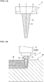
- the primary joining rotary tool F has a coupling part F1 and a stirring pin F2.
- the primary joining rotary tool F corresponds to a rotary tool in the scope of claim for patent.
- the primary joining rotary tool F is made of, for example, tool steel.
- the coupling part F1 is a part to be coupled to a rotary shaft D of a friction stir device shown in Figure 1B .
- the coupling part F1 has a cylindrical shape, and has screw holes B, B for fastening bolts.
- the stirring pin F2 hangs down from the coupling part F1, and is coaxial with the coupling part F1.
- the stirring pin F2 has a tapered shape so as to have a smaller diameter as it goes away from the coupling part F1.
- the stirring pin F2 has a spiral groove F3 formed on the outer peripheral surface thereof. In this embodiment, the spiral groove F3 is formed so as to rotate in a counter-clockwise direction as it goes downward because the primary joining rotary tool F is rotated in the clockwise direction.
- the spiral groove F3 is formed so as to rotate in the clockwise direction as it goes downward.
- plastically fluidized metal is led to a front end side through the spiral groove F3 when friction stirring is performed. Thereby, an amount of metal to be leaked to the outside of metal members (a base member 2 and a lid plate 5 to be described later) to be joined, can be reduced.
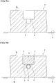
- the preliminary joining rotary tool G has a shoulder part G1 and a stirring pin G2.
- the preliminary joining rotary tool G is made of tool steel.
- the shoulder part G1 is a part to be coupled to the rotary shaft D of the friction stir device, and also a part to hold plastically fluidized metal, as shown in Figure 2B .
- the shoulder part G1 has a cylindrical shape.
- a lower end face of the shoulder part G1 is formed as a recessed portion in order to prevent the fluidized metal from flowing out to the outside.
- the stirring pin G2 hangs down from the shoulder part G1, and is coaxial with the shoulder part G1.
- the stirring pin G2 has a tapered shape so as to have a smaller diameter as it goes away from the shoulder part G1.
- the stirring pin G2 has a spiral groove G3 formed on the outer peripheral surface thereof.
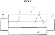
- the heat exchanger plate 1 according to this embodiment is constituted mainly by a base member 2 and a lid plate 5 as shown in Figure 3 .
- the base member 2 has an approximately rectangular parallelepiped shape.
- a concave groove 3 and a lid groove 4 are formed in the base member 2.
- Material of the base member 2 is not specially limited as far as friction stirring can be performed.
- the material is an aluminum alloy in this embodiment.
- the concave groove 3 is formed in the middle of the base member 2 so as to pass through from one side surface to the other side surface.
- the concave groove 3 is formed on a bottom surface of the lid groove 4 so as to be recessed.
- a bottom part of the concave groove 3 has an arc shape.
- the concave groove 3 is open on a front surface 2a side of the base member 2.
- the lid groove 4 has a larger width than the concave groove 3, and is formed continuously with the concave groove 3 on the front surface 2a side of the concave groove 3.
- the lid groove 4 has a rectangle shape in a sectional view, and is open on the front surface 2a side thereof.
- the lid plate 5 is a plate-like member to be inserted into the lid groove 4.
- the lid plate 5 is made of an aluminum alloy equivalent to the material of the base member 2.
- the lid plate 5 has the same shape as a hollow part of the lid groove 4 in order to be inserted into the lid groove 4 without a gap.
- a pair of side walls of the lid groove 4 and a pair of side surfaces of the lid plate 5 are abutted respectively, so that butting portions J, J are formed.
- Each of the butting portions J, J is joined over a whole length in a depth direction thereof by friction stirring.
- a space enclosed with the concave groove 3 of the heat exchanger plate 1 and a bottom surface of the lid plate 5 is a channel through which a fluid flows.
- a method for manufacturing a heat exchanger plate according to the first embodiment will be described.
- a preparing process, a lid groove closing process, a tab member disposing process, a preliminary joining process, and a primary joining process are performed.
- the preparing process is a process to prepare the base member 2.
- the base member 2 is fixed to a pedestal K with a clamp (not shown).
- the concave groove 3 and the lid groove 4 are formed by means of cutting with use of an endmill or the like.
- the base member 2 having the concave groove 3 and the lid groove 4 formed in advance by die-casting, extrusion molding, or the like, may be used.
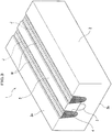
- the lid groove closing process is a process where the lid plate 5 is inserted into the lid groove 4. Side walls of the lid groove 4 and side surfaces of the lid plate 5 are abutted respectively, so that the butting portions J, J are formed. A front surface of the lid plate 5 is flush with the front surface 2a.
- the tab member disposing process is a process where tab members 10, 10 are disposed at side surfaces of the base member 2.
- a tab member 10 is a member in which a start position or an end position for friction stirring to be described later is set.
- a side surface of a tab member 10 abuts on one of the opposing side surfaces of the base member 2, and is disposed on extension lines of the butting portions J, J.
- a tab member 10 is made of an aluminum alloy equivalent to the material of the base member 2.
- a tab member 10 is joined by welding inner corner portions formed with the tab member 10 and the base member 2.
- the preliminary joining process is a process where friction stir welding is preliminarily performed to the butting portions J, J with use of the preliminary joining rotary tool G.
- a start position and an end position of the preliminary joining process are not particularly limited as far as they are located on a surface or surfaces of the base member 2 and the tab members 10. In this embodiment, they are set on a surface of a tab member 10.
- a start position of the preliminary joining process is set on a surface of one tab member 10, and friction stir welding is performed over the whole length of one butting portion J.
- the plasticized region W1 is formed along a moving locus of the preliminary joining rotary tool G. And thus, after the preliminary joining rotary tool is moved to the other tab member 10, the preliminary joining rotary tool is made a turn in the surface of the other tab member 10 as it is. Then, friction stir welding is performed over the whole length of the other butting portion J. After the preliminary joining rotary tool G is moved to the one tab member 10, the preliminary joining rotary tool G is removed from the one tab member 10.
- the primary joining process is a process where friction stir welding is performed for the butting portions J, J with use of the primary joining rotary tool F. It is preferable that a start position and an end position of the primary joining process are set on the surface of a tab member 10.
- a pull-out hole formed by the preliminary joining rotary tool G may be used.
- a pilot hole is formed in the tab member 10 in advance, and the primary joining rotary tool F may be inserted through the pilot hole.
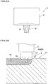
- the primary joining rotary tool F is inserted until a front end of the primary joining rotary tool F reaches a bottom surface of the lid groove 4.
- the stirring pin F2 is made to have a length longer than a depth of the lid groove 4, the coupling part F1 does not abut on the base member 2 nor the lid plate 5 even when the front end of the stirring pin F2 reaches the bottom surface of the lid groove 4. That is, in the primary joining process, a bottom surface of the coupling part F1 does not press upon the front surface of the base member 2 nor the front surface of the lid plate 5.
- the plasticized region W is formed along the moving locus of the primary joining rotary tool F. It is preferable that a distance between a butting portion J and the concave groove 3 is set so that plastically fluidized material does not flow in the concave groove 3 while the primary joining process is being performed. After finishing the primary joining process, the tab members 10 are removed from the base member 2 by cutting.
- a deburring process where burrs generated by friction stirring are removed by cutting may be performed.
- the surfaces of the base member 2 and the lid plate 5 can be finished to be smooth.
- each of the preliminary joining rotary tool G and the primary joining rotary tool F is moved in a procedure of writing in one stroke in which each of the preliminary joining rotary tool G and the primary joining rotary tool F is not removed from the base member 2 halfway in the friction stirring. Therefore, time and labor of the work can be reduced.
- friction stirring may be performed discontinuously so that the plasticized region W1 by the preliminary joining rotary tool G is formed intermittently.
- the butting portions J, J may be joined by welding.
- a tab member 10 and the base member 2 may be preliminarily joined by the preliminary joining rotary tool G.
- a heat exchanger plate according to the second embodiment is different from the first embodiment in the point that this heat exchanger plate is provided with a heating medium pipe 6.
- the heating medium pipe 6 is a member through which a fluid flows.
- a preparing process, a heating medium pipe insertion process, a lid groove closing process, a preliminary joining process, and a primary joining process are performed.
- the preparing process is a process to prepare the base member 2.
- the heating medium pipe insertion process is a process to insert the heating medium pipe 6 into the concave groove 3. Sizes and the like of the concave groove 3 and the heating medium pipe 6 can be appropriately set. In this embodiment, an outer diameter of the heating medium pipe 6 is substantially the same as a width and a depth of the concave groove 3.
- the lid groove closing process is a process to insert the lid plate 5 into the lid groove 4.
- Each butting portion J is formed by butting of a side wall of the lid groove 4 on a side surface of the lid plate 5.
- the preliminary joining process is a process to perform joining preliminarily for the butting portions J.
- the preliminary joining process is performed in the same manner as the first embodiment.
- the primary joining process is a process to perform friction stir welding for the butting portions J, J with use of the primary joining rotary tool F.
- the primary joining process is performed in the same manner as the first embodiment.
- the plasticized regions W, W are formed along the moving locus of the primary joining rotary tool F. Each plasticized region W is formed over the whole depth of one of the butting portions J, J.
- the method for manufacturing the heat exchanger plate according to the second embodiment can exhibit the effect substantially equivalent to the first embodiment. Further, the heat exchanger plate 1A equipped with the heating medium pipe 6 can be easily manufactured.
- the shapes of the concave groove 3, the lid groove 4, the lid plate 5, and the heating medium pipe 6 according to the first embodiment and the second embodiment are just examples, and these may be other shapes.
- a build-up welding may be performed to eliminate the level difference.
- a metal member is placed on the surface of the plasticized region W, and friction stir welding may be performed for this metal member and the base member 2 with a rotary tool.
- the lid plate 5 may be directly inserted into the concave groove 3 without the lid groove 4.
- the gap part Q may be embedded by the primary joining process.
- the gap part Q is formed by the concave groove 3, the bottom surface of the lid plate 5, and the heating medium pipe 6.
- plastically fluidized material made by the primary joining rotary tool F is flowed in the gap part Q.
- the gap part Q around the heating medium pipe 6 is filled with metal, so that air-tightness and water-tightness can be further improved.
Landscapes
- Engineering & Computer Science (AREA)
- Mechanical Engineering (AREA)
- Pressure Welding/Diffusion-Bonding (AREA)
Priority Applications (2)
| Application Number | Priority Date | Filing Date | Title |
|---|---|---|---|
| EP16201515.0A EP3159092B1 (en) | 2012-10-10 | 2013-10-08 | Method for manufacturing heat exchanger plate |
| EP16201512.7A EP3156166B1 (en) | 2012-10-10 | 2013-10-08 | Method for friction stir welding |
Applications Claiming Priority (3)
| Application Number | Priority Date | Filing Date | Title |
|---|---|---|---|
| JP2012224718 | 2012-10-10 | ||
| JP2013019354A JP2014094409A (ja) | 2012-10-10 | 2013-02-04 | 伝熱板の製造方法及び摩擦攪拌接合方法 |
| PCT/JP2013/077378 WO2014057947A1 (ja) | 2012-10-10 | 2013-10-08 | 伝熱板の製造方法及び摩擦攪拌接合方法 |
Related Child Applications (4)
| Application Number | Title | Priority Date | Filing Date |
|---|---|---|---|
| EP16201512.7A Division EP3156166B1 (en) | 2012-10-10 | 2013-10-08 | Method for friction stir welding |
| EP16201512.7A Division-Into EP3156166B1 (en) | 2012-10-10 | 2013-10-08 | Method for friction stir welding |
| EP16201515.0A Division EP3159092B1 (en) | 2012-10-10 | 2013-10-08 | Method for manufacturing heat exchanger plate |
| EP16201515.0A Division-Into EP3159092B1 (en) | 2012-10-10 | 2013-10-08 | Method for manufacturing heat exchanger plate |
Publications (3)
| Publication Number | Publication Date |
|---|---|
| EP2907611A1 EP2907611A1 (en) | 2015-08-19 |
| EP2907611A4 EP2907611A4 (en) | 2016-06-22 |
| EP2907611B1 true EP2907611B1 (en) | 2019-03-13 |
Family
ID=50477415
Family Applications (3)
| Application Number | Title | Priority Date | Filing Date |
|---|---|---|---|
| EP13845258.6A Not-in-force EP2907611B1 (en) | 2012-10-10 | 2013-10-08 | Method for producing heat exchanger plate |
| EP16201512.7A Active EP3156166B1 (en) | 2012-10-10 | 2013-10-08 | Method for friction stir welding |
| EP16201515.0A Active EP3159092B1 (en) | 2012-10-10 | 2013-10-08 | Method for manufacturing heat exchanger plate |
Family Applications After (2)
| Application Number | Title | Priority Date | Filing Date |
|---|---|---|---|
| EP16201512.7A Active EP3156166B1 (en) | 2012-10-10 | 2013-10-08 | Method for friction stir welding |
| EP16201515.0A Active EP3159092B1 (en) | 2012-10-10 | 2013-10-08 | Method for manufacturing heat exchanger plate |
Country Status (7)
| Country | Link |
|---|---|
| US (3) | US9821419B2 (enExample) |
| EP (3) | EP2907611B1 (enExample) |
| JP (1) | JP2014094409A (enExample) |
| KR (3) | KR20170091187A (enExample) |
| CN (1) | CN104507630B (enExample) |
| TW (1) | TWI529018B (enExample) |
| WO (1) | WO2014057947A1 (enExample) |
Families Citing this family (43)
| Publication number | Priority date | Publication date | Assignee | Title |
|---|---|---|---|---|
| JP2014094409A (ja) * | 2012-10-10 | 2014-05-22 | Nippon Light Metal Co Ltd | 伝熱板の製造方法及び摩擦攪拌接合方法 |
| EP2937169B8 (en) * | 2012-12-19 | 2018-10-17 | Mitsubishi Heavy Industries Engineering, Ltd. | Welded material manufacturing method and welding jig |
| CA2922119C (en) * | 2013-08-26 | 2021-03-02 | Lockheed Martin Corporation | Method of friction stir welding a tube to an element using a tubular anvil; structure manufactured by this method |
| WO2015122093A1 (ja) * | 2014-02-17 | 2015-08-20 | 日本軽金属株式会社 | 接合方法 |
| JP6655868B2 (ja) * | 2014-08-28 | 2020-03-04 | 三菱重工エンジニアリング株式会社 | 摩擦撹拌接合用のエンドタブ、及び接合材の製造方法 |
| JP6413108B2 (ja) * | 2014-10-08 | 2018-10-31 | カルソニックカンセイ株式会社 | 半導体冷却装置の製造方法 |
| JP6432277B2 (ja) * | 2014-10-22 | 2018-12-05 | 新日鐵住金株式会社 | チタン材と鉄鋼材料の接合方法 |
| JP6471462B2 (ja) * | 2014-11-05 | 2019-02-20 | 日本軽金属株式会社 | 液冷ジャケットの製造方法 |
| WO2016072211A1 (ja) * | 2014-11-05 | 2016-05-12 | 日本軽金属株式会社 | 液冷ジャケットの製造方法及び液冷ジャケット |
| JP6471461B2 (ja) * | 2014-11-05 | 2019-02-20 | 日本軽金属株式会社 | 液冷ジャケットの製造方法 |
| JP6350334B2 (ja) * | 2015-02-19 | 2018-07-04 | 日本軽金属株式会社 | 接合方法及び複合圧延材の製造方法 |
| WO2016181770A1 (ja) * | 2015-05-14 | 2016-11-17 | 日本軽金属株式会社 | 接合方法 |
| JP6372515B2 (ja) * | 2015-08-26 | 2018-08-15 | 日本軽金属株式会社 | 液冷ジャケットの製造方法及び液冷ジャケット |
| CN107921575A (zh) * | 2015-08-26 | 2018-04-17 | 日本轻金属株式会社 | 接合方法、液冷套筒的制造方法及液冷套筒 |
| KR101687250B1 (ko) * | 2015-11-04 | 2016-12-16 | 대우조선해양 주식회사 | 마찰교반용접 방법 |
| CN105772935A (zh) * | 2016-04-01 | 2016-07-20 | 中国电子科技集团公司第三十八研究所 | 用于焊接窄台阶水道盖板的搅拌头、窄台阶水道盖板焊接工艺 |
| CN108472763B (zh) * | 2016-07-01 | 2020-07-24 | 日本轻金属株式会社 | 传热板的制造方法 |
| JP6777226B2 (ja) * | 2017-05-11 | 2020-10-28 | 日本軽金属株式会社 | 接合方法 |
| JP2019058933A (ja) | 2017-09-27 | 2019-04-18 | 日本軽金属株式会社 | 液冷ジャケットの製造方法 |
| JP2019058934A (ja) | 2017-09-27 | 2019-04-18 | 日本軽金属株式会社 | 液冷ジャケットの製造方法 |
| JP6769427B2 (ja) | 2017-12-18 | 2020-10-14 | 日本軽金属株式会社 | 液冷ジャケットの製造方法 |
| CN111032268B (zh) * | 2018-03-16 | 2022-04-22 | 日本轻金属株式会社 | 导热板的制造方法和摩擦搅拌接合方法 |
| JP6927128B2 (ja) | 2018-04-02 | 2021-08-25 | 日本軽金属株式会社 | 液冷ジャケットの製造方法 |
| JP2019181473A (ja) | 2018-04-02 | 2019-10-24 | 日本軽金属株式会社 | 液冷ジャケットの製造方法 |
| JP6927130B2 (ja) * | 2018-04-10 | 2021-08-25 | 日本軽金属株式会社 | 伝熱板の製造方法 |
| JP7024573B2 (ja) * | 2018-04-20 | 2022-02-24 | 日本軽金属株式会社 | 伝熱板の製造方法及び摩擦攪拌接合方法 |
| WO2019239663A1 (ja) * | 2018-06-14 | 2019-12-19 | 日本軽金属株式会社 | 複合スラブの製造方法 |
| JP7086773B2 (ja) * | 2018-07-25 | 2022-06-20 | 株式会社東芝 | 溶接方法、溶接物の製造方法、及び溶接物 |
| JP2020032429A (ja) * | 2018-08-27 | 2020-03-05 | 日本軽金属株式会社 | 伝熱板の製造方法 |
| KR20200040398A (ko) * | 2018-10-10 | 2020-04-20 | 안범모 | 디스플레이 제조 공정용 접합부품 및 디스플레이 제조 공정 장비 |
| JP7246161B2 (ja) * | 2018-10-25 | 2023-03-27 | 日本発條株式会社 | 接合体 |
| JP7070389B2 (ja) | 2018-12-19 | 2022-05-18 | 日本軽金属株式会社 | 接合方法 |
| JP2019158334A (ja) * | 2019-06-11 | 2019-09-19 | 日本軽金属株式会社 | 熱交換器 |
| CN114173980A (zh) * | 2019-08-09 | 2022-03-11 | 日本轻金属株式会社 | 接合方法 |
| KR20210020436A (ko) * | 2019-08-14 | 2021-02-24 | (주)포인트엔지니어링 | 접합부품 |
| JP2021087961A (ja) * | 2019-12-02 | 2021-06-10 | 日本軽金属株式会社 | 伝熱板の製造方法 |
| JP7377533B2 (ja) * | 2020-03-03 | 2023-11-10 | 京浜ラムテック株式会社 | 金属構造体の製造方法 |
| US11872650B2 (en) * | 2020-05-15 | 2024-01-16 | Lockheed Martin Corporation | Systems and methods for friction stir welding a cold plate |
| JP7537256B2 (ja) * | 2020-12-04 | 2024-08-21 | 日本軽金属株式会社 | 回転ツール、接合装置および接合方法 |
| JP7425781B2 (ja) | 2021-12-16 | 2024-01-31 | 株式会社東芝 | 異種金属の接合方法、および接合装置 |
| US20240399493A1 (en) * | 2023-06-05 | 2024-12-05 | Ut-Battelle, Llc | Friction pressure welding of similar and/or dissimilar materials |
| FR3149529A1 (fr) * | 2023-06-06 | 2024-12-13 | Safran | Module métallique et procédé de fabrication d’un tel module métallique. |
| KR102886282B1 (ko) * | 2024-08-12 | 2025-11-19 | 주식회사 두웰이엔지 | 버스바 제조 장치, 제조 방법 및 이에 의하여 제조된 버스바 |
Family Cites Families (77)
| Publication number | Priority date | Publication date | Assignee | Title |
|---|---|---|---|---|
| US5611479A (en) * | 1996-02-20 | 1997-03-18 | Rockwell International Corporation | Friction stir welding total penetration technique |
| JP3283434B2 (ja) | 1997-03-06 | 2002-05-20 | 住友軽金属工業株式会社 | 摩擦攪拌接合用治具及びそれを用いた摩擦攪拌接合方法 |
| GB9713209D0 (en) * | 1997-06-20 | 1997-08-27 | British Aerospace | Friction welding metal components |
| JP3589863B2 (ja) * | 1997-07-23 | 2004-11-17 | 株式会社日立製作所 | 構造体および摩擦攪拌接合方法 |
| US5893507A (en) * | 1997-08-07 | 1999-04-13 | The United States Of America As Represented By The Administrator Of The National Aeronautics And Space Administration | Auto-adjustable pin tool for friction stir welding |
| GB9808607D0 (en) | 1998-04-22 | 1998-06-24 | Welding Inst | Corrosion resistant enclosure and methods for its manufacture |
| US6294264B1 (en) * | 1999-03-30 | 2001-09-25 | Cryovac, Inc. | Oriented cook-in film with good interply adhesion |
| JP3575748B2 (ja) * | 2000-03-06 | 2004-10-13 | 株式会社日立製作所 | 摩擦攪拌接合方法 |
| JP3867475B2 (ja) * | 2000-04-28 | 2007-01-10 | マツダ株式会社 | 金属部材の処理方法 |
| JP2001321965A (ja) | 2000-05-19 | 2001-11-20 | Nissho Iwai Hitetsu Hanbai Kk | 摩擦撹拌接合によるすみ接合法 |
| JP4467723B2 (ja) * | 2000-06-30 | 2010-05-26 | 昭和電工株式会社 | 摩擦撹拌接合法 |
| JP3818084B2 (ja) * | 2000-12-22 | 2006-09-06 | 日立電線株式会社 | 冷却板とその製造方法及びスパッタリングターゲットとその製造方法 |
| JP4385533B2 (ja) | 2001-03-02 | 2009-12-16 | 日本軽金属株式会社 | ヒートプレートの製造方法 |
| CN100553851C (zh) * | 2001-03-07 | 2009-10-28 | 昭和电工株式会社 | 摩擦搅动接合方法以及用于制造接合的贴靠元件的方法 |
| WO2002078893A2 (en) * | 2001-03-29 | 2002-10-10 | Mazda Motor Corporation | Friction stir welding method and apparatus |
| SE520928C2 (sv) | 2001-05-11 | 2003-09-16 | Svensk Kaernbraenslehantering | Verktyg för friktionsomrörningssvetsning |
| US6726084B2 (en) * | 2001-06-15 | 2004-04-27 | Lockheed Martin Corporation | Friction stir heating/welding with pin tool having rough distal region |
| KR20040012950A (ko) * | 2001-06-20 | 2004-02-11 | 쇼와 덴코 가부시키가이샤 | 냉각판 및 그 제조 방법 |
| US7097091B2 (en) | 2001-07-25 | 2006-08-29 | Hitachi, Ltd. | Friction stir welding method and component part welded by the method |
| US6637109B2 (en) * | 2001-09-27 | 2003-10-28 | Emerson Energy Systems Ab | Method for manufacturing a heat sink |
| JP2003136256A (ja) * | 2001-10-31 | 2003-05-14 | Mazda Motor Corp | 摩擦攪拌用回転工具及びそれを用いた処理方法 |
| JP4134562B2 (ja) | 2002-01-30 | 2008-08-20 | 日本軽金属株式会社 | アルミニウム系構造体の製造方法 |
| JP4325260B2 (ja) | 2003-04-15 | 2009-09-02 | 日本軽金属株式会社 | 伝熱素子の製造方法 |
| US7163136B2 (en) | 2003-08-29 | 2007-01-16 | The Boeing Company | Apparatus and method for friction stir welding utilizing a grooved pin |
| US20060008677A1 (en) * | 2004-07-12 | 2006-01-12 | General Electric Company | Ceramic bonding composition, method of making, and article of manufacture incorporating the same |
| US7234626B2 (en) * | 2004-10-22 | 2007-06-26 | Edison Welding Institute, Inc. | Method of friction stir welding and retractable shoulderless variable penetration friction stir welding tool for same |
| US7416102B1 (en) | 2004-10-22 | 2008-08-26 | Edison Welding Institute, Inc. | Method of friction stir welding and multi-section faced shoulderless retractable variable penetration friction stir welding tool for same |
| JP2007111716A (ja) * | 2005-10-19 | 2007-05-10 | Showa Denko Kk | クランプ装置、接合装置および接合方法 |
| JP2007160370A (ja) | 2005-12-15 | 2007-06-28 | Hino Motors Ltd | 摩擦撹拌接合ツール |
| JP4814631B2 (ja) | 2005-12-22 | 2011-11-16 | 富士重工業株式会社 | 摩擦攪拌接合方法 |
| US7581665B2 (en) * | 2006-01-04 | 2009-09-01 | The Boeing Company | Methods and apparatus for retractable pin friction stir welding and spot welding |
| JP5151036B2 (ja) | 2006-02-07 | 2013-02-27 | 株式会社日立製作所 | 摩擦攪拌接合方法 |
| WO2008040715A2 (de) * | 2006-10-05 | 2008-04-10 | Basf Se | Verfahren zur herstellung wasserabsorbierender polymerpartikel durch polymerisation von tropfen einer monomerlösung |
| JP2008254047A (ja) * | 2007-04-06 | 2008-10-23 | Mitsubishi Heavy Ind Ltd | 熱交換板およびその製造方法 |
| JP2008254046A (ja) * | 2007-04-06 | 2008-10-23 | Mitsubishi Heavy Ind Ltd | 熱交換板 |
| CN102248276B (zh) | 2007-04-16 | 2013-10-30 | 日本轻金属株式会社 | 传热板及其制造方法 |
| CN101772395B (zh) | 2007-08-10 | 2013-01-16 | 日本轻金属株式会社 | 接合方法及接合构造物的制造方法 |
| JP2009090297A (ja) | 2007-10-04 | 2009-04-30 | Nippon Light Metal Co Ltd | 接合方法 |
| JP5136072B2 (ja) | 2008-01-15 | 2013-02-06 | 日本軽金属株式会社 | 液冷ジャケットの製造方法 |
| CN101952079B (zh) | 2008-02-21 | 2014-04-02 | 日本轻金属株式会社 | 传热板的制造方法 |
| WO2009142070A1 (ja) * | 2008-05-20 | 2009-11-26 | 日本軽金属株式会社 | 伝熱板の製造方法及び伝熱板 |
| JP4962423B2 (ja) | 2008-06-16 | 2012-06-27 | 日本軽金属株式会社 | 伝熱板の製造方法 |
| JP5434251B2 (ja) * | 2009-05-13 | 2014-03-05 | 日本軽金属株式会社 | 伝熱板の製造方法 |
| KR101213247B1 (ko) * | 2008-06-27 | 2012-12-18 | 니폰게이긴조쿠가부시키가이샤 | 전열판의 제조 방법 및 전열판 |
| US20100081005A1 (en) * | 2008-09-26 | 2010-04-01 | Jong-Ning Aoh | Friction Stir Welding Tool and Weld Metal Structure with Plural Onion Rings |
| KR101249186B1 (ko) | 2008-10-06 | 2013-04-02 | 니폰게이긴조쿠가부시키가이샤 | 전열판 제조 방법 |
| JP4782186B2 (ja) | 2008-12-15 | 2011-09-28 | 三菱重工業株式会社 | 重ね摩擦攪拌接合方法及びその方法で製造された構造体 |
| JP5262822B2 (ja) * | 2009-02-23 | 2013-08-14 | 日本軽金属株式会社 | 液冷ジャケットの製造方法 |
| JP2010284693A (ja) * | 2009-06-12 | 2010-12-24 | Mitsubishi Heavy Ind Ltd | 冷却板およびその製造方法 |
| JP5654219B2 (ja) | 2009-07-14 | 2015-01-14 | 富士重工業株式会社 | 摩擦攪拌接合用回転ツール |
| JP5267381B2 (ja) * | 2009-08-19 | 2013-08-21 | 日本軽金属株式会社 | 伝熱板の製造方法 |
| US8464926B2 (en) * | 2009-10-30 | 2013-06-18 | Wisconsin Alumni Research Foundation | Method of friction stir welding dissimilar metals and workpiece assemblies formed thereby |
| CN102085598B (zh) * | 2009-12-03 | 2015-10-14 | 鸿富锦精密工业(深圳)有限公司 | 摩擦搅拌接合方法 |
| KR101598733B1 (ko) | 2010-01-15 | 2016-02-29 | 미츠비시 쥬고교 가부시키가이샤 | 접합 부재의 제조 방법 및 마찰 교반 접합 장치 |
| US20110315367A1 (en) * | 2010-06-25 | 2011-12-29 | Romero Guillermo L | Fluid cooled assembly and method of making the same |
| US9003649B1 (en) * | 2010-06-25 | 2015-04-14 | Maxq Technology, Llc | Method of making a two-sided fluid cooled assembly |
| US8966759B1 (en) * | 2010-06-25 | 2015-03-03 | Maxq Technology, Llc | Method of making a fluid cooled assembly |
| JP5644217B2 (ja) | 2010-07-12 | 2014-12-24 | 日本軽金属株式会社 | 空隙形成用回転ツール及び空隙形成方法 |
| JP5740871B2 (ja) | 2010-08-31 | 2015-07-01 | スズキ株式会社 | 異種金属材料の接合方法及び異種金属材料接合体 |
| JP5803069B2 (ja) | 2010-08-31 | 2015-11-04 | スズキ株式会社 | 異種金属材料の接合方法 |
| EP2650075B1 (en) * | 2010-11-25 | 2022-01-19 | Nittan Valve Co., Ltd. | Deburring device for friction welding machine |
| JP5662953B2 (ja) * | 2011-01-19 | 2015-02-04 | 日本軽金属株式会社 | 接合方法 |
| JP5957720B2 (ja) | 2011-08-30 | 2016-07-27 | 日本軽金属株式会社 | 摩擦攪拌接合方法 |
| EP2745972B1 (en) * | 2011-08-19 | 2021-11-10 | Nippon Light Metal Company, Ltd. | Friction stir welding method |
| JP5567530B2 (ja) * | 2011-08-19 | 2014-08-06 | 日立オートモティブシステムズ株式会社 | 摩擦攪拌接合構造およびパワー半導体装置 |
| JP5957719B2 (ja) * | 2011-08-19 | 2016-07-27 | 日本軽金属株式会社 | 摩擦攪拌接合方法 |
| JP2014094409A (ja) * | 2012-10-10 | 2014-05-22 | Nippon Light Metal Co Ltd | 伝熱板の製造方法及び摩擦攪拌接合方法 |
| KR101422584B1 (ko) * | 2013-01-11 | 2014-07-24 | 주식회사 우신이엠시 | 마찰교반용접방법 |
| US20140367452A1 (en) * | 2013-06-18 | 2014-12-18 | Focus: Hope | Method of friction stir welding |
| WO2015107716A1 (ja) * | 2014-01-14 | 2015-07-23 | 日本軽金属株式会社 | 液冷ジャケットの製造方法 |
| US8857696B1 (en) * | 2014-04-01 | 2014-10-14 | King Fahd University Of Petroleum And Minerals | Method and tool for friction stir welding |
| US20170197274A1 (en) * | 2014-07-10 | 2017-07-13 | Megastir Technologies Llc | Mechanical flow joining of high melting temperature materials |
| WO2016072211A1 (ja) * | 2014-11-05 | 2016-05-12 | 日本軽金属株式会社 | 液冷ジャケットの製造方法及び液冷ジャケット |
| JP2016128178A (ja) * | 2015-01-09 | 2016-07-14 | 株式会社Ihi | 摩擦撹拌接合方法 |
| JP2016128177A (ja) * | 2015-01-09 | 2016-07-14 | 株式会社Ihi | 摩擦撹拌接合装置 |
| CN107921575A (zh) * | 2015-08-26 | 2018-04-17 | 日本轻金属株式会社 | 接合方法、液冷套筒的制造方法及液冷套筒 |
| US20180200829A1 (en) * | 2017-01-19 | 2018-07-19 | Hamilton Sundstrand Corporation | Friction stir welding for compact parts |
-
2013
- 2013-02-04 JP JP2013019354A patent/JP2014094409A/ja active Pending
- 2013-10-08 KR KR1020177021368A patent/KR20170091187A/ko not_active Ceased
- 2013-10-08 EP EP13845258.6A patent/EP2907611B1/en not_active Not-in-force
- 2013-10-08 WO PCT/JP2013/077378 patent/WO2014057947A1/ja not_active Ceased
- 2013-10-08 EP EP16201512.7A patent/EP3156166B1/en active Active
- 2013-10-08 EP EP16201515.0A patent/EP3159092B1/en active Active
- 2013-10-08 KR KR1020187026026A patent/KR20180104172A/ko not_active Ceased
- 2013-10-08 CN CN201380040199.4A patent/CN104507630B/zh active Active
- 2013-10-08 US US14/433,183 patent/US9821419B2/en active Active
- 2013-10-08 KR KR20157002543A patent/KR20150034223A/ko not_active Ceased
- 2013-10-09 TW TW102136457A patent/TWI529018B/zh active
-
2017
- 2017-10-16 US US15/784,731 patent/US10518369B2/en not_active Expired - Fee Related
-
2019
- 2019-07-22 US US16/518,612 patent/US20190344392A1/en not_active Abandoned
Non-Patent Citations (1)
| Title |
|---|
| None * |
Also Published As
| Publication number | Publication date |
|---|---|
| CN104507630B (zh) | 2016-10-19 |
| CN104507630A (zh) | 2015-04-08 |
| JP2014094409A (ja) | 2014-05-22 |
| US9821419B2 (en) | 2017-11-21 |
| TW201414560A (zh) | 2014-04-16 |
| TWI529018B (zh) | 2016-04-11 |
| EP3156166A2 (en) | 2017-04-19 |
| EP3159092A2 (en) | 2017-04-26 |
| EP2907611A1 (en) | 2015-08-19 |
| US20180043483A1 (en) | 2018-02-15 |
| EP3156166B1 (en) | 2020-11-25 |
| EP2907611A4 (en) | 2016-06-22 |
| EP3159092A3 (en) | 2017-05-03 |
| EP3159092B1 (en) | 2020-11-25 |
| US10518369B2 (en) | 2019-12-31 |
| KR20180104172A (ko) | 2018-09-19 |
| EP3156166A3 (en) | 2017-04-26 |
| US20150273637A1 (en) | 2015-10-01 |
| US20190344392A1 (en) | 2019-11-14 |
| WO2014057947A1 (ja) | 2014-04-17 |
| KR20150034223A (ko) | 2015-04-02 |
| KR20170091187A (ko) | 2017-08-08 |
Similar Documents
| Publication | Publication Date | Title |
|---|---|---|
| EP2907611B1 (en) | Method for producing heat exchanger plate | |
| US11413700B2 (en) | Method for manufacturing heat transfer plate | |
| JP2017042816A5 (enExample) | ||
| JP4962423B2 (ja) | 伝熱板の製造方法 | |
| JP2017042817A5 (enExample) | ||
| WO2019150610A1 (ja) | 液冷ジャケットの製造方法 | |
| JP2019058933A (ja) | 液冷ジャケットの製造方法 | |
| WO2019123678A1 (ja) | 液冷ジャケットの製造方法 | |
| WO2019123679A1 (ja) | 液冷ジャケットの製造方法 | |
| JP6885285B2 (ja) | 液冷ジャケットの製造方法 | |
| US20210170521A1 (en) | Production method of heat transmitting plate | |
| JP6201882B2 (ja) | 伝熱板の製造方法及び伝熱板 | |
| JP5195098B2 (ja) | 伝熱板の製造方法 | |
| JP6577696B2 (ja) | 内部に流路を設けない複合板の製造方法 | |
| JP6274257B2 (ja) | 伝熱板の製造方法及び内部に流路を設けない複合板の製造方法 | |
| JP2018065163A (ja) | 伝熱板の製造方法及び摩擦攪拌接合方法 |
Legal Events
| Date | Code | Title | Description |
|---|---|---|---|
| PUAI | Public reference made under article 153(3) epc to a published international application that has entered the european phase |
Free format text: ORIGINAL CODE: 0009012 |
|
| 17P | Request for examination filed |
Effective date: 20150217 |
|
| AK | Designated contracting states |
Kind code of ref document: A1 Designated state(s): AL AT BE BG CH CY CZ DE DK EE ES FI FR GB GR HR HU IE IS IT LI LT LU LV MC MK MT NL NO PL PT RO RS SE SI SK SM TR |
|
| AX | Request for extension of the european patent |
Extension state: BA ME |
|
| DAX | Request for extension of the european patent (deleted) | ||
| RA4 | Supplementary search report drawn up and despatched (corrected) |
Effective date: 20160520 |
|
| RIC1 | Information provided on ipc code assigned before grant |
Ipc: B23K 20/12 20060101AFI20160513BHEP Ipc: B23K 103/10 20060101ALI20160513BHEP Ipc: B23K 101/14 20060101ALI20160513BHEP Ipc: B23K 20/24 20060101ALI20160513BHEP Ipc: B23P 15/26 20060101ALI20160513BHEP |
|
| GRAP | Despatch of communication of intention to grant a patent |
Free format text: ORIGINAL CODE: EPIDOSNIGR1 |
|
| STAA | Information on the status of an ep patent application or granted ep patent |
Free format text: STATUS: GRANT OF PATENT IS INTENDED |
|
| INTG | Intention to grant announced |
Effective date: 20180917 |
|
| RIN1 | Information on inventor provided before grant (corrected) |
Inventor name: HORI, HISASHI Inventor name: SEO, NOBUSHIRO |
|
| GRAS | Grant fee paid |
Free format text: ORIGINAL CODE: EPIDOSNIGR3 |
|
| GRAA | (expected) grant |
Free format text: ORIGINAL CODE: 0009210 |
|
| STAA | Information on the status of an ep patent application or granted ep patent |
Free format text: STATUS: THE PATENT HAS BEEN GRANTED |
|
| AK | Designated contracting states |
Kind code of ref document: B1 Designated state(s): AL AT BE BG CH CY CZ DE DK EE ES FI FR GB GR HR HU IE IS IT LI LT LU LV MC MK MT NL NO PL PT RO RS SE SI SK SM TR |
|
| REG | Reference to a national code |
Ref country code: GB Ref legal event code: FG4D |
|
| REG | Reference to a national code |
Ref country code: CH Ref legal event code: EP Ref country code: AT Ref legal event code: REF Ref document number: 1107045 Country of ref document: AT Kind code of ref document: T Effective date: 20190315 |
|
| REG | Reference to a national code |
Ref country code: IE Ref legal event code: FG4D |
|
| REG | Reference to a national code |
Ref country code: DE Ref legal event code: R096 Ref document number: 602013052435 Country of ref document: DE |
|
| REG | Reference to a national code |
Ref country code: NL Ref legal event code: MP Effective date: 20190313 |
|
| REG | Reference to a national code |
Ref country code: LT Ref legal event code: MG4D |
|
| PG25 | Lapsed in a contracting state [announced via postgrant information from national office to epo] |
Ref country code: NO Free format text: LAPSE BECAUSE OF FAILURE TO SUBMIT A TRANSLATION OF THE DESCRIPTION OR TO PAY THE FEE WITHIN THE PRESCRIBED TIME-LIMIT Effective date: 20190613 Ref country code: LT Free format text: LAPSE BECAUSE OF FAILURE TO SUBMIT A TRANSLATION OF THE DESCRIPTION OR TO PAY THE FEE WITHIN THE PRESCRIBED TIME-LIMIT Effective date: 20190313 Ref country code: SE Free format text: LAPSE BECAUSE OF FAILURE TO SUBMIT A TRANSLATION OF THE DESCRIPTION OR TO PAY THE FEE WITHIN THE PRESCRIBED TIME-LIMIT Effective date: 20190313 Ref country code: FI Free format text: LAPSE BECAUSE OF FAILURE TO SUBMIT A TRANSLATION OF THE DESCRIPTION OR TO PAY THE FEE WITHIN THE PRESCRIBED TIME-LIMIT Effective date: 20190313 |
|
| PG25 | Lapsed in a contracting state [announced via postgrant information from national office to epo] |
Ref country code: HR Free format text: LAPSE BECAUSE OF FAILURE TO SUBMIT A TRANSLATION OF THE DESCRIPTION OR TO PAY THE FEE WITHIN THE PRESCRIBED TIME-LIMIT Effective date: 20190313 Ref country code: NL Free format text: LAPSE BECAUSE OF FAILURE TO SUBMIT A TRANSLATION OF THE DESCRIPTION OR TO PAY THE FEE WITHIN THE PRESCRIBED TIME-LIMIT Effective date: 20190313 Ref country code: RS Free format text: LAPSE BECAUSE OF FAILURE TO SUBMIT A TRANSLATION OF THE DESCRIPTION OR TO PAY THE FEE WITHIN THE PRESCRIBED TIME-LIMIT Effective date: 20190313 Ref country code: LV Free format text: LAPSE BECAUSE OF FAILURE TO SUBMIT A TRANSLATION OF THE DESCRIPTION OR TO PAY THE FEE WITHIN THE PRESCRIBED TIME-LIMIT Effective date: 20190313 Ref country code: BG Free format text: LAPSE BECAUSE OF FAILURE TO SUBMIT A TRANSLATION OF THE DESCRIPTION OR TO PAY THE FEE WITHIN THE PRESCRIBED TIME-LIMIT Effective date: 20190613 Ref country code: GR Free format text: LAPSE BECAUSE OF FAILURE TO SUBMIT A TRANSLATION OF THE DESCRIPTION OR TO PAY THE FEE WITHIN THE PRESCRIBED TIME-LIMIT Effective date: 20190614 |
|
| REG | Reference to a national code |
Ref country code: AT Ref legal event code: MK05 Ref document number: 1107045 Country of ref document: AT Kind code of ref document: T Effective date: 20190313 |
|
| PG25 | Lapsed in a contracting state [announced via postgrant information from national office to epo] |
Ref country code: EE Free format text: LAPSE BECAUSE OF FAILURE TO SUBMIT A TRANSLATION OF THE DESCRIPTION OR TO PAY THE FEE WITHIN THE PRESCRIBED TIME-LIMIT Effective date: 20190313 Ref country code: AL Free format text: LAPSE BECAUSE OF FAILURE TO SUBMIT A TRANSLATION OF THE DESCRIPTION OR TO PAY THE FEE WITHIN THE PRESCRIBED TIME-LIMIT Effective date: 20190313 Ref country code: PT Free format text: LAPSE BECAUSE OF FAILURE TO SUBMIT A TRANSLATION OF THE DESCRIPTION OR TO PAY THE FEE WITHIN THE PRESCRIBED TIME-LIMIT Effective date: 20190713 Ref country code: SK Free format text: LAPSE BECAUSE OF FAILURE TO SUBMIT A TRANSLATION OF THE DESCRIPTION OR TO PAY THE FEE WITHIN THE PRESCRIBED TIME-LIMIT Effective date: 20190313 Ref country code: ES Free format text: LAPSE BECAUSE OF FAILURE TO SUBMIT A TRANSLATION OF THE DESCRIPTION OR TO PAY THE FEE WITHIN THE PRESCRIBED TIME-LIMIT Effective date: 20190313 Ref country code: IT Free format text: LAPSE BECAUSE OF FAILURE TO SUBMIT A TRANSLATION OF THE DESCRIPTION OR TO PAY THE FEE WITHIN THE PRESCRIBED TIME-LIMIT Effective date: 20190313 Ref country code: RO Free format text: LAPSE BECAUSE OF FAILURE TO SUBMIT A TRANSLATION OF THE DESCRIPTION OR TO PAY THE FEE WITHIN THE PRESCRIBED TIME-LIMIT Effective date: 20190313 Ref country code: CZ Free format text: LAPSE BECAUSE OF FAILURE TO SUBMIT A TRANSLATION OF THE DESCRIPTION OR TO PAY THE FEE WITHIN THE PRESCRIBED TIME-LIMIT Effective date: 20190313 |
|
| PG25 | Lapsed in a contracting state [announced via postgrant information from national office to epo] |
Ref country code: SM Free format text: LAPSE BECAUSE OF FAILURE TO SUBMIT A TRANSLATION OF THE DESCRIPTION OR TO PAY THE FEE WITHIN THE PRESCRIBED TIME-LIMIT Effective date: 20190313 Ref country code: PL Free format text: LAPSE BECAUSE OF FAILURE TO SUBMIT A TRANSLATION OF THE DESCRIPTION OR TO PAY THE FEE WITHIN THE PRESCRIBED TIME-LIMIT Effective date: 20190313 |
|
| REG | Reference to a national code |
Ref country code: DE Ref legal event code: R097 Ref document number: 602013052435 Country of ref document: DE |
|
| PG25 | Lapsed in a contracting state [announced via postgrant information from national office to epo] |
Ref country code: AT Free format text: LAPSE BECAUSE OF FAILURE TO SUBMIT A TRANSLATION OF THE DESCRIPTION OR TO PAY THE FEE WITHIN THE PRESCRIBED TIME-LIMIT Effective date: 20190313 Ref country code: IS Free format text: LAPSE BECAUSE OF FAILURE TO SUBMIT A TRANSLATION OF THE DESCRIPTION OR TO PAY THE FEE WITHIN THE PRESCRIBED TIME-LIMIT Effective date: 20190713 |
|
| PLBE | No opposition filed within time limit |
Free format text: ORIGINAL CODE: 0009261 |
|
| STAA | Information on the status of an ep patent application or granted ep patent |
Free format text: STATUS: NO OPPOSITION FILED WITHIN TIME LIMIT |
|
| PG25 | Lapsed in a contracting state [announced via postgrant information from national office to epo] |
Ref country code: DK Free format text: LAPSE BECAUSE OF FAILURE TO SUBMIT A TRANSLATION OF THE DESCRIPTION OR TO PAY THE FEE WITHIN THE PRESCRIBED TIME-LIMIT Effective date: 20190313 |
|
| 26N | No opposition filed |
Effective date: 20191216 |
|
| PG25 | Lapsed in a contracting state [announced via postgrant information from national office to epo] |
Ref country code: SI Free format text: LAPSE BECAUSE OF FAILURE TO SUBMIT A TRANSLATION OF THE DESCRIPTION OR TO PAY THE FEE WITHIN THE PRESCRIBED TIME-LIMIT Effective date: 20190313 |
|
| PG25 | Lapsed in a contracting state [announced via postgrant information from national office to epo] |
Ref country code: TR Free format text: LAPSE BECAUSE OF FAILURE TO SUBMIT A TRANSLATION OF THE DESCRIPTION OR TO PAY THE FEE WITHIN THE PRESCRIBED TIME-LIMIT Effective date: 20190313 |
|
| PG25 | Lapsed in a contracting state [announced via postgrant information from national office to epo] |
Ref country code: MC Free format text: LAPSE BECAUSE OF FAILURE TO SUBMIT A TRANSLATION OF THE DESCRIPTION OR TO PAY THE FEE WITHIN THE PRESCRIBED TIME-LIMIT Effective date: 20190313 |
|
| REG | Reference to a national code |
Ref country code: CH Ref legal event code: PL |
|
| PG25 | Lapsed in a contracting state [announced via postgrant information from national office to epo] |
Ref country code: LU Free format text: LAPSE BECAUSE OF NON-PAYMENT OF DUE FEES Effective date: 20191008 Ref country code: LI Free format text: LAPSE BECAUSE OF NON-PAYMENT OF DUE FEES Effective date: 20191031 Ref country code: CH Free format text: LAPSE BECAUSE OF NON-PAYMENT OF DUE FEES Effective date: 20191031 |
|
| REG | Reference to a national code |
Ref country code: BE Ref legal event code: MM Effective date: 20191031 |
|
| PG25 | Lapsed in a contracting state [announced via postgrant information from national office to epo] |
Ref country code: BE Free format text: LAPSE BECAUSE OF NON-PAYMENT OF DUE FEES Effective date: 20191031 |
|
| PG25 | Lapsed in a contracting state [announced via postgrant information from national office to epo] |
Ref country code: IE Free format text: LAPSE BECAUSE OF NON-PAYMENT OF DUE FEES Effective date: 20191008 |
|
| PG25 | Lapsed in a contracting state [announced via postgrant information from national office to epo] |
Ref country code: CY Free format text: LAPSE BECAUSE OF FAILURE TO SUBMIT A TRANSLATION OF THE DESCRIPTION OR TO PAY THE FEE WITHIN THE PRESCRIBED TIME-LIMIT Effective date: 20190313 |
|
| PG25 | Lapsed in a contracting state [announced via postgrant information from national office to epo] |
Ref country code: MT Free format text: LAPSE BECAUSE OF FAILURE TO SUBMIT A TRANSLATION OF THE DESCRIPTION OR TO PAY THE FEE WITHIN THE PRESCRIBED TIME-LIMIT Effective date: 20190313 Ref country code: HU Free format text: LAPSE BECAUSE OF FAILURE TO SUBMIT A TRANSLATION OF THE DESCRIPTION OR TO PAY THE FEE WITHIN THE PRESCRIBED TIME-LIMIT; INVALID AB INITIO Effective date: 20131008 |
|
| PGFP | Annual fee paid to national office [announced via postgrant information from national office to epo] |
Ref country code: GB Payment date: 20211022 Year of fee payment: 9 Ref country code: DE Payment date: 20211020 Year of fee payment: 9 |
|
| PGFP | Annual fee paid to national office [announced via postgrant information from national office to epo] |
Ref country code: FR Payment date: 20211022 Year of fee payment: 9 |
|
| PG25 | Lapsed in a contracting state [announced via postgrant information from national office to epo] |
Ref country code: MK Free format text: LAPSE BECAUSE OF FAILURE TO SUBMIT A TRANSLATION OF THE DESCRIPTION OR TO PAY THE FEE WITHIN THE PRESCRIBED TIME-LIMIT Effective date: 20190313 |
|
| REG | Reference to a national code |
Ref country code: DE Ref legal event code: R119 Ref document number: 602013052435 Country of ref document: DE |
|
| GBPC | Gb: european patent ceased through non-payment of renewal fee |
Effective date: 20221008 |
|
| PG25 | Lapsed in a contracting state [announced via postgrant information from national office to epo] |
Ref country code: FR Free format text: LAPSE BECAUSE OF NON-PAYMENT OF DUE FEES Effective date: 20221031 Ref country code: DE Free format text: LAPSE BECAUSE OF NON-PAYMENT OF DUE FEES Effective date: 20230503 |
|
| PG25 | Lapsed in a contracting state [announced via postgrant information from national office to epo] |
Ref country code: GB Free format text: LAPSE BECAUSE OF NON-PAYMENT OF DUE FEES Effective date: 20221008 |