EP2902575B1 - Beschlaganordnung - Google Patents
Beschlaganordnung Download PDFInfo
- Publication number
- EP2902575B1 EP2902575B1 EP14193491.9A EP14193491A EP2902575B1 EP 2902575 B1 EP2902575 B1 EP 2902575B1 EP 14193491 A EP14193491 A EP 14193491A EP 2902575 B1 EP2902575 B1 EP 2902575B1
- Authority
- EP
- European Patent Office
- Prior art keywords
- scissor
- arm
- fitting
- scissor arm
- arrangement
- Prior art date
- Legal status (The legal status is an assumption and is not a legal conclusion. Google has not performed a legal analysis and makes no representation as to the accuracy of the status listed.)
- Active
Links
Images


Classifications
-
- E—FIXED CONSTRUCTIONS
- E05—LOCKS; KEYS; WINDOW OR DOOR FITTINGS; SAFES
- E05D—HINGES OR SUSPENSION DEVICES FOR DOORS, WINDOWS OR WINGS
- E05D15/00—Suspension arrangements for wings
- E05D15/48—Suspension arrangements for wings allowing alternative movements
- E05D15/52—Suspension arrangements for wings allowing alternative movements for opening about a vertical as well as a horizontal axis
- E05D15/5205—Suspension arrangements for wings allowing alternative movements for opening about a vertical as well as a horizontal axis with horizontally-extending checks
-
- E—FIXED CONSTRUCTIONS
- E05—LOCKS; KEYS; WINDOW OR DOOR FITTINGS; SAFES
- E05Y—INDEXING SCHEME ASSOCIATED WITH SUBCLASSES E05D AND E05F, RELATING TO CONSTRUCTION ELEMENTS, ELECTRIC CONTROL, POWER SUPPLY, POWER SIGNAL OR TRANSMISSION, USER INTERFACES, MOUNTING OR COUPLING, DETAILS, ACCESSORIES, AUXILIARY OPERATIONS NOT OTHERWISE PROVIDED FOR, APPLICATION THEREOF
- E05Y2800/00—Details, accessories and auxiliary operations not otherwise provided for
- E05Y2800/37—Length, width or depth adjustment
-
- E—FIXED CONSTRUCTIONS
- E05—LOCKS; KEYS; WINDOW OR DOOR FITTINGS; SAFES
- E05Y—INDEXING SCHEME ASSOCIATED WITH SUBCLASSES E05D AND E05F, RELATING TO CONSTRUCTION ELEMENTS, ELECTRIC CONTROL, POWER SUPPLY, POWER SIGNAL OR TRANSMISSION, USER INTERFACES, MOUNTING OR COUPLING, DETAILS, ACCESSORIES, AUXILIARY OPERATIONS NOT OTHERWISE PROVIDED FOR, APPLICATION THEREOF
- E05Y2900/00—Application of doors, windows, wings or fittings thereof
- E05Y2900/10—Application of doors, windows, wings or fittings thereof for buildings or parts thereof
- E05Y2900/13—Type of wing
- E05Y2900/148—Windows
Definitions
- the present invention relates to a fitting arrangement for a window, a door or the like according to the preamble of claim 1.
- the wing is not simply hinge side about one or more pivot bearings, which are formed approximately in the manner of hinges, pivotally mounted on the frame around the pivot bearing. But it is a scissors fitting provided which couples the wing, in particular at the top, in addition to the frame.
- Such a scissor arm improves the stability of the mounting of the wing to the frame not only in a pivoting opening of the wing, in particular by supporting the wing against vertically downwardly directed tensile forces acting on the wing due to gravity, but also allows the wing to tilt open , wherein the scissors fitting on the one hand, the extent to which the wing can be tilted limited and on the other hand, the tilted wing on the tilting axis opposite and thus wegkippenden away from the frame side (indirectly) coupled to the frame.
- the scissors fitting comprises a scissor arm and a scissors link, which are hinged together to spread in the manner of a scissor mechanism 'can.
- the scissor arm is generally elongate and is coupled at said second coupling point via a band angle pivotally connected to a scissors bearing provided on the frame.
- At the other end of the scissor arm is usually coupled to the wing, but not rigid, but out in a slot or a groove on the wing between different positions.
- the scissor arm is usually coupled at a fixed spaced from the ends of the articulation point with the scissor link, which in turn is coupled at said (fixed) first coupling point with the wing.
- the wing side, on the scissors fitting is arranged to be tilted away from the frame, since the scissor arm and the scissor arms, which are aligned parallel to each other with the wing closed, can open this way when tilting the wing.
- the effective length of the scissors fitting i. the distance between the first coupling point at which the scissor arm is coupled to the wing and at which thus the wing is held by the scissors fitting, and that point on the frame on which the scissor arm is coupled via the bank angle with the scissors bearing is adjusted correctly . Because the effective length of the scissor fitting has an influence on the correct orientation of the wing to the frame, in particular to the height of the distant side of the blade with rotatably opened wing.
- shortening the effective length of the scissors fitting causes the wing to be raised relative to the frame, while the wing decreases in lengthening the effective length of the bracket relative to the frame.
- raising and lowering of the wing is to be understood in each case so that the band-distant side of the wing offset when lifting the wing with respect to the band-side side up and is offset when lowering the wing opposite the band-side side down.
- the wing relative to the frame can be raised or lowered so that when you close the open wing, ie upon pivoting of the wing to the frame out, the wing not fit is pivoted into the frame, but even before reaching the closed position with its top or bottom on the corresponding side of the frame can accrue and is swung along this grinding in the frame.
- two parts of the scissors fitting and the scissor bearing comprehensive support structure relative to each other can be variably fixed in different positions.
- a screw and a nut may be provided by which the two parts are coupled together.
- tightening or loosening the screw relative to the nut can cause the parts to move relative to one another.
- the screw and the But mother can also serve only to set a set by manually moving the parts effective length of the scissors fitting.
- Adjusting the effective length of the scissors fitting during assembly or as part of a, for example due to a deformation of the wing required, readjustment is carried out by means of tools, such as a screwdriver or a special tool.
- the adjustment of the effective length of the scissors fitting must usually be made by a person skilled in the art.
- the readjustment of a lowered grand piano therefore also remains completely out if, for example, laypersons do not realize that a readjustment is required or the costs for the professional implementation are shy. This poses a safety risk, since an incorrectly set effective length of the scissors fitting due to the increased wear can lead to damage to the wing bearing.
- a fitting arrangement with a scissors fitting according to the preamble of claim 1, wherein the effective length of the scissors fitting is automatically adjusted when turning the wing, is from the DE 197 18 325 C1 known.
- the extension arm of the fitting assembly is slidably mounted with respect to a hinged frame side pivotally mounted adjusting member and connected thereto via spring-loaded, plate-shaped locking elements.
- the locking elements are part of an adjustable coupling element, by which a malposition of the wing is automatically corrected by shortening the effective length of the scissors fitting when turning the wing.
- Another generic fitting arrangement is known, wherein the stay and the adjusting piece held over respective fine teeth and fixed by means of a clamping screw as a locking element.
- the adjustment of the effective length is not manually required - a manual adjustment does not even have to be possible - but takes place automatically when closing the wing. It can be exploited in particular that when the sash is closed by the frame a correct, i. to the frame tailor-made, alignment is enforced. Even if the wing is misaligned in the open state and therefore runs against the frame when it is closed, closing it through the interaction with the frame results in the wing ultimately being forced into the correct orientation. The said coupling element can be adjusted automatically due to this interaction.
- the coupling element connects the two variably fixable parts together, the effective length of the scissors fitting can be changed in particular by adjusting the coupling element.
- the coupling element can use the interactions occurring during closing of the wing to adapt the position of the two parts which can be variably fixed to one another.
- the coupling of the parts caused by the coupling element can first be released by closing the wing and can be restored at the latest when the fully closed position of the wing is reached.
- the parts can advantageously be connected to each other again in the relative position, which by the closed wing is given and therefore corresponds to a correct orientation of the wing.
- an embodiment according to the invention also has an advantageous effect on the simplicity of mounting the fitting arrangement.
- the scissors fitting can initially be set to a maximum or at least particularly long effective length during assembly of the fitting arrangement.
- the wing then does not necessarily have to be mounted in the exact correct orientation, but in particular can initially be mounted slightly suspended (i.e., slightly lowered) on the window frame.
- the sash When closing for the first time, the sash then pops up on the frame and is pushed upwards by it.
- the effective length of the scissors fitting due to the embodiment of the invention shortened straight to the correct level, i. in such a way that the wing is correctly aligned relative to the frame and thus, when the wing is next closed, it is pivoted into the frame in a precisely fitting manner.
- the wing e.g. due to the action of gravity should lower again, this independent adjustment is automatically again. Since the degree of misalignment of the sash occurring during assembly or after installation is generally low, the variability of the two parts of the fitting arrangement which can be variably fixed in different positions need not be particularly extensive and may be limited, for example, to positions which are at most differ by a few centimeters.
- the two variably fixable parts are displaceable relative to each other and coupled to each other via a one-way coupling forming the coupling element, which allows a sliding movement of the parts in one direction and blocked in the other direction.
- the various relative positions are thus in this fitting arrangement by moving the said parts relative to each other.
- parts are not freely displaceable, since they are coupled to one another via a particularly suitable coupling element, namely a one-way clutch.
- the two parts can be displaced relative to one another only in one direction (for example towards each other). In the other direction (example, away from each other), however, they are blocked against shifting.
- the one-way clutch rigidly couples the two parts together in a direction of displacement, but allows at least one movement of the parts relative to one another in the opposite direction, without the parts necessarily being completely decoupled from each other.
- the one-way clutch can couple the two parts permanently, so that the parts are displaceable relative to one another in the said one direction, but are not completely detached from one another.
- the displaceability of the parts may be limited relative to each other.
- the one-way clutch a displacement of the parts towards each other to basically allow.
- the distance by which the parts may be displaced may be limited by the one-way clutch or otherwise (such as by stops on the parts themselves or other elements of the fitting assembly).
- the one-way clutch is designed to enable a shortening of the effective length of the scissor fitting shortening sliding movement of the parts and to block the effective length of the scissor fitting extending sliding movement of the parts.
- the one-way clutch between a shear bearing side end portion of the scissor arm and one for attachment of the scissor arm provided on the pivot bearing connecting member, in particular a carrying handle or a band angle effective.
- a support bracket may be substantially formed as an angle which is pivotally mounted with one leg over a band angle on the scissor bearing, while the other leg is coupled by means of the one-way clutch with the scissor arm.
- the support bracket in a simple manner allow the storage of an angled, in particular perpendicular, aligned to a pivot axis of the scissors bearing scissor arm.
- connection component can also be embodied in other ways, as long as it allows the attachment of the scissor arm to the band angle.
- neither the scissor arm nor the connecting component nor the band angle must be made in one piece.
- further elements can bring about or support the attachment of the scissor arm to the belt angle and thus the coupling to the scissors bearing.
- the change in the effective length of the scissors fitting is obtained in such a fitting arrangement in particular by the scissor arm and the connecting member are displaced relative to each other, whereby the distance of the first coupling point, at which the scissor arm is coupled to the wing, of the by the band angle or the scissor bearing defined pivot axis changed.
- the one-way clutch is integrated in the band angle or in the scissor bearing.
- band angle or scissors bearing may be formed in several parts, wherein at least two of these parts are displaceable relative to each other and wherein between these two parts, the one-way clutch acts in the manner mentioned.
- the relative displaceability can, for example, between a mounting portion, about which the scissors bearing can be screwed about to the frame, and a storage section the scissor bearing, which serves for the pivotable mounting of the scissor arm or of a connecting component coupled thereto.
- the one-way clutch has a latching device.
- a locking device provides a simple mechanism to fulfill the function of the one-way clutch, namely to enable displacement of two coupled by means of the one-way clutch divider relative to each other in one direction and to block in the opposite direction.
- the latching device that must be done for the displacement of the two parts in one direction no manual or caused by a further element loosening and then bringing back the coupling of the two parts, but that the mere displacement of the two parts in the a direction causes the loosening and re-coupling.
- the locking effected by the latching means in particular stepped, approximately at regular intervals, carried out, so that in each case a displacement by a certain amount (latching step) a correspondingly shortened or extended effective length of the scissors fitting is set.
- the latching device comprises a toothing formed on one of the displaceable parts and a counter-toothing cooperating therewith and formed on the other part.
- a toothing formed on one of the displaceable parts and a counter-toothing cooperating therewith and formed on the other part.
- the toothing and the counter-toothing cooperate in this case precisely due to their respective design in such a way that they allow the displaceable parts to slide along one another but block in the other direction.
- the toothing may in particular have an asymmetrical tooth form.
- an asymmetrical tooth shape can be achieved that the interaction of the teeth and the counter teeth, which may also have a, albeit not necessarily equally, asymmetric tooth shape, in which a displacement allows displacement, but blocks it in the other direction of displacement.
- the tooth flanks of the toothing facing toward one side can run obliquely to a longitudinal axis of the scissor arm and the tooth flanks of the toothing pointing towards the opposite side extend at least substantially at right angles to the longitudinal axis.
- the tooth flanks are aligned neither parallel nor perpendicular to the longitudinal axis, but have an average angle of, for example, between 20 ° and 70 °.
- the tooth flanks of the counter-toothing can be designed accordingly, but just opposite.
- the teeth and the counter-teeth mesh are perpendicular to the longitudinal axis aligned tooth flanks of the teeth on perpendicular to the longitudinal axis aligned tooth flanks of the counter teeth and obliquely to the longitudinal axis aligned tooth flanks of the teeth on obliquely to the longitudinal axis aligned tooth flanks of the counter teeth.
- the locking device comprises a pawl which is movable, in particular pivotable, mounted on one of the displaceable parts and engages in preferably formed by a toothing recesses of the other part.
- the said counter-toothing may be formed on the pawl, so that the pawl engages with this counter-toothing in the latching recesses of the respective other part.
- the mobility of the pawl allows in that the engagement of the pawl in the recesses is at least temporarily canceled by the pawl moves out of the engaging position out, in particular pivots is.
- the pawl is biased by means of a spring element in any displacement movements of the parts blocking blocking position.
- any displacement movements of the parts blocking blocking position is to be understood such that the displaceable parts can not be moved relative to each other without having to adjust the pawl from its locked position for this purpose.
- the displacement of the parts itself causes the pawl is moved out of the locked position.
- the pawl and the recesses are formed such that a force exerted on the displaceable parts displacement force in a direction of displacement leads to a displacement of the pawl out of the blocking position, so that the parts can be moved in this direction, while a Displacement force in the other direction of displacement leads to no displacement of the pawl, so that the parts are blocked against displacement in this other direction.
- Such a biased pawl can be used to ensure that the one-way clutch, the sliding parts in the direction to be blocked, i. in particular against due to gravity on the wing and the fitting arrangement acting forces reliably coupled.
- the pawl can advantageously also be designed so that it can be manually moved against its bias from the locked position to allow, if necessary exceptionally, a sliding of the sliding parts in the otherwise locked direction.
- the pawl is mounted directly on a shear bearing side end portion of the scissor arm.
- a coupling of the scissor arm can be provided with a connecting member or the band angle, so that the pawl can be effective in the context of this coupling.
- the pawl does not extend very far away from the frame in this way, even with torsionally open or tilt-open wing, so that it is not exposed and thus can be avoided that it is accidentally actuated releasing.
- the pawl is mounted on a wing of the window or the door facing the underside of the scissor arm, wherein a recess of the scissor arm allows at least partial access to the pawl from the top of the scissor arm.
- the pawl is thus arranged substantially concealed and protected so that unintentional release of the coupling of the two displaceable parts is avoided.
- access to the pawl is possible, at least from a certain angle which is untypical with usual operation of the wing (from above).
- the pawl thus, if necessary, manually, about without tools or by means of a pin or screwdriver, be solved. This may be necessary, for example, if overcorrection has occurred and the orientation of the sash has been changed beyond the correct position.
- the scissor arm and the scissor arms are not hinged together at a fixed point, but the point at which the scissor arm and the scissor arms are connected to each other is adjustable.
- this articulation point be adjusted in the longitudinal direction of the scissor fitting, ie parallel to the extension of the scissors fitting, when the scissors fitting is closed and thus the scissor arm and the scissor arms are aligned parallel to each other, which is about the case with closed or rotatably opened wing the case.
- the fitting assembly according to this embodiment need not be fundamentally different from conventional fitting arrangements, but only in that the coupling of the scissor arm with the scissor arm has a variable articulation point, through which the effective length of the scissor fitting can be changed in a simple manner.
- a mechanism is provided, although allowing an adjustment of the position of said articulation point, in particular when tilting the wing, the point of articulation after reaching the correct position but, in particular during the pivoting opening of the wing, at the wing is usually worn by the scissor fitting, determines and keeps stable.
- the coupling element comprises at least one toothing formed on the scissor arm and at least one counter toothing formed on the scissor arm, wherein the toothing and the counter toothing are adapted to interlock when the scissor arm and the scissor arm are aligned parallel to each other are.
- the intermeshing of the toothing and the counter toothing advantageously leads to the fact that the variable common articulation point of the scissor arm and the scissor arm to a certain, in particular position at the time of the intervention.
- the scissor arm may comprise a clamping part, in which case the clamping part may have a toothing as part of the scissor arm.
- the toothing and the counter toothing interlock at least when the scissor arm and the scissor arm are aligned parallel to each other, that is approximately in the closed position of the scissors fitting. It is conceivable that they also interlock in other positions of the scissors fitting. Basically, it is sufficient if the teeth mesh with closed scissors fitting and thus set the otherwise changeable effective length of the scissor fitting. Because only in rotatable state of the wing of the wing is supported by the scissor fitting and depends on the inclination and thus a possible malalignment of the wing of the effective length of the scissors fitting.
- the wing when tilted have no malposition, since the wing with the tilting axis facing side (usually bottom, but can also be the top) is supported on the frame and thereby aligned correctly. Therefore, in the tilt-open state of the wing, the effective length of the then sheared shear fitting need not be fixed.
- the automatic adjustment of the teeth and counter teeth to each other then takes place when closing the tilt-open wing.
- the wing in the tilt-open state has a correct orientation, the shortened compared to the misalignment (with hanging wing) or extended (with too high raised wing) can be , Since the teeth and the counter teeth do not interlock with the scissors fitting disengaged, the point of articulation between the scissor arm and the scissors arm is initially freely adjustable within the scope of the possible adjustability and takes the correct orientation of the wing and thus automatically correct Position.
- the effective length of the scissor fitting is set correctly by this, but must still be fixed, ie fixed, so that it is maintained even with a subsequent pivotal opening of the wing. This happens when closing the tilt-open sash. Then namely the scissors fitting closes and interlock the teeth and the counter teeth so that they prevent the position of the articulation point can continue to change.
- the effective length of the scissors fitting is determined and remains as long as the teeth and counter teeth remain in engagement with each other, ie as long as the scissor fitting remains closed, ie in particular at a rotational opening of the wing.
- the automatic adaptation of the effective length of the scissors fitting does not take place during closing in the embodiment last described of the revolving wing, but when closing the tilt-open wing.
- the toothing is formed on a longitudinal side of the scissor arm facing the wing
- the counter toothing is formed on a longitudinal side of the scissor arm facing the wing.
- the one longitudinal side of the scissor arm or of the scissor arm is meant with the longitudinal side facing the wing, which in the tilting direction, ie in the direction of the wing and away from the frame, points at tilt-opened wing.
- the toothing can also be formed on a longitudinal side of the scissor arm facing away from the wing and the counter toothing on a longitudinal side of the scissor arm facing away from the wing.
- two toothings arranged on opposite longitudinal sides of the scissor arm may be formed on the scissor arm and two on opposite sides of the scissor arm Longitudinal sides of the scissor arm arranged counter teeth may be formed.
- the teeth and the counter teeth are advantageously each arranged so that they can interlock when closing the scissors fitting, so when pivoting the scissor arm and the scissor arm relative to each other in a mutually parallel alignment.
- the teeth and counter teeth are different relative to each other in particular with respect to a longitudinal alignment, so that is determined by the meshing of the thus arranged teeth and counter teeth of the articulation point in its respective position.
- the toothing is designed to be pivotable on the scissor arm and is spring-biased in the direction of the counter-toothing and / or that the counter-toothing is designed to be pivotable on the scissor arm and spring-biased in the direction of the toothing.
- the teeth (or counter teeth) can thus be swung out with open scissors fitting due to the bias in the direction of the counter teeth (or teeth). This has the consequence that when closing the scissors fitting, for example, when closing the tilt-open wing, the teeth and the counter teeth already meet before the scissor arm and the scissor arms are completely aligned parallel to each other.
- At least one tooth or some teeth of the toothing can already engage in the counter toothing (or vice versa) before the toothing and the counter toothing are aligned in parallel and engage flush with one another.
- This premature interaction together with the spring preload can advantageously result in that the intermeshing of the toothing and the counter toothing tends to set a slightly shortened (for example by a tooth pitch of the toothing) compared to the current wing alignment effective length of the scissor fitting in which the wing slightly raised when closing becomes. Due to the slightly shorter effective length, the Fitting arrangement then just be particularly well suited to hold the rotating open wing against gravity so stable that it does not run when closing on the frame.
- said articulation point is defined by an engaging in a slot of the scissor arm pin of the scissor arm or by engaging in a slot of the scissor arm pin of the scissor arm.
- a determination of the position of the pin in the slot for fixing the point of articulation does not need to be done by an interaction of the pin with the slot, but can also be done elsewhere, such as by means of said teeth and counter teeth, between the scissor arm and the scissor arm.
- the slot has an internal toothing
- the pin has a radial extension which is adapted to engage in the internal toothing, when the scissor arm and the scissor arms are aligned parallel to each other.
- the extension can point away from the internal toothing when the scissors fitting is released, so that the pin can be arranged substantially freely in the slot.
- the extension can already engage in the internal toothing, if the scissors arm and the scissor arms are not yet completely aligned parallel to each other. Similar to the previously described pivotable and preloaded toothing, this can bring about an advantageous slight shortening of the effective length of the scissors fitting relative to the correct orientation of the blade predetermined by the abutment of the wing on the frame, by slightly lifting the wing.
- the toothing is formed on a scissor arm facing the top of the scissor arm.
- a clamping part can be provided which is rotatably coupled to the articulation point and laterally displaceable along the axis of rotation with the scissor arm.
- the counter-toothing can be provided opposite the toothing on a side facing the scissor arm side of the clamping part.
- Such an embodiment has the advantage that no structural adaptation of the scissor arm must be made. Rather, existing systems can only be converted to the new system by replacing the scissor link, and not additionally the scissors arm.
- the clamping part on a side facing the scissor arm and / or the scissor arm on a side facing the clamping part have at least one elevation, wherein the elevation is formed to effect a lateral displacement of the clamping part along the axis of rotation during tilting, whereby the toothing of Scissor arm can be brought into engagement with the counter-toothing of the clamping part.
- the clamping part on the side facing the scissor arm have two elevations, which are advantageously arranged on opposite sides of the Anlenk Vietnameses.
- the two protrusions may be arranged in opposite end regions of the scissor arm.
- the scissor arm on the side facing the clamping part has two elevations, which may be arranged on opposite sides of the articulation point.
- the first coupling point can also be designed to be frictional. This has the advantage that when closing the wing from the tilted position a contact pressure between the clamping part and the scissor arm is generated, whereby first engages the longitudinal toothing of the clamping part in the opposite counter-toothing of the scissor arm before the scissor fitting can zuscheren.
- a frictional first coupling point can also be provided in any other embodiment.
- any other coupling point can be made frictional.
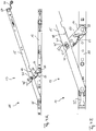
- the respective fitting arrangement 11 comprises a scissor fitting 13, which has a scissor arm 15, a scissor arm 17 and a scissor cuff 19.
- the scissor arm 15 and the scissors link 17 are elongate and articulated at an articulation point 21 coupled to each other, wherein the articulation point 21 at one end of the scissor arm 17, but spaced from one end of the scissor arm 15 is arranged.
- the scissors tuft 19 may be secured to an upper surface of a sash, not shown, of a window, door or the like and serves to connect the scissors fitting 13 to the sash.
- the scissors turret 19 has a first coupling point 23, at which the scissors link 17 is pivotally coupled to the Scherenstulp 19 with the opposite end of the articulation point 21 and in this way can be coupled indirectly with a respective wing.
- the scissors arm 15 is thus connected on the one hand via the scissors link 17 with the scissor plate 19.
- the scissor arm 15 also engages directly with an end adjacent to the articulation point 21 into a slot 25 of the scissor-type collar 19, so that the scissor arm 15 articulates with the scissor-type cuff 19 is coupled, but this coupling has no fixed coupling point, but along the extension of the elongated hole 25 is variable.
- the scissors fitting 13 in an example in Fig. 4 and 6 Shake off the position shown. It is limited by the slot 25, how far the scissors fitting 13 can be opened (in Fig. 4 and 6 the maximum position is shown).
- the connecting member 27 is formed as a support bracket in the form of an angle with two legs, which is connected with one leg with the scissor arm 15 and with the other leg with the band angle 31.
- the scissors arm 15 and the carrying handle 27 are not rigidly coupled to each other, but are slidably coupled relative to one another in the longitudinal direction via a coupling element designed as a one-way clutch 33.
- the one-way clutch 33 is formed such that the scissor arm 15 can be moved in the direction of the band angle 31 relative to the support bracket 27, but is blocked against displacement in the opposite direction. In this way, the effective length of the scissors fitting 13 can be automatically shortened when the scissor arm 15 is urged in the direction of the band angle 31. An automatic extension is excluded.
- the one-way clutch 33 is shown enlarged. It can be seen that the one-way clutch 33 has a latching device 35 which comprises a toothing 37 on the carrying handle 27 and a counter-toothing 39 arranged on the scissor arm 15. The counter-toothing 39 is formed on a pivotally mounted on the scissor arm 15 pawl 41.
- the pawl 41 is between the FIGS. 2A and 2B shown positions pivoted so that the pawl 41 engage with the counter teeth 39 in the recesses formed by the teeth 37 as shown or can be solved from these. In this case, the pawl 41 by an unrepresented spring element in the in Fig. 2A biased engaged position shown biased.
- the tooth flanks of the toothing 37 facing the band angle 31 are aligned perpendicular to the longitudinal axis L of the scissor arm 15, while the tooth flanks facing away from the band angle 31 are aligned obliquely to the longitudinal axis L.
- the pointing away from the band angle 31 tooth flanks of the counter teeth 39 are aligned perpendicular to the longitudinal axis L, while the band angle 31 facing tooth flanks are aligned obliquely to the longitudinal axis L.
- the abutting vertical tooth flanks of the toothing 37 and the counter teeth 39 block a displacement movement of the scissor arm 15 relative to the carrying handle 27.
- the obliquely oriented tooth flanks of the toothing 37 and the counter teeth 39 slide along one another, whereby the pawl 41 is raised against the spring bias and enables a displacement movement of the scissor arm 15 relative to the carrying handle 27.
- the pawl 41 pivots back due to the bias and engages with the counter teeth 39 again in the teeth 37, so that the relative orientation of the scissor arm 15 relative to the support bracket 27 is secured again.
- the described first fitting arrangement allows an automatic shortening of the effective length of the scissors fitting 13 when the scissor arm 15 is urged in the direction of the belt angle 27, as is the case in particular by running of the wing on the frame when closing the rotary-opened wing.
- An extension of the effective length is not automatically possible, but only by manually releasing the pawl 41.
- the pawl 41 is mounted on the respective wing-facing underside of the scissor arm 15 and protected in this way against unintentional adjustment.
- a recess in the scissor arm 15 is provided through which access to the pawl 41 from the top of the scissor arm 15 is made possible.
- the pawl 41 can be actuated through the recess 43 to fit them into the in Fig. 2B to pivot shown position and to allow a manual extension of the effective length of the scissors fitting 13.
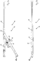
- first and second embodiments of a fitting assembly 11 differ from the first fitting assembly 11 described above essentially in that the scissor arm 15 is not relative to the support bracket 27 slidably, but rigidly connected to the support bracket 27, and that instead the articulation point 21, on which the scissor arm 15 is pivotally connected to the scissors link 17, not fixed, but is variable.
- the scissors link 17 for coupling with the scissor arm 15 has a pin 45 which engages in a slot formed in the scissor arm 15 slot 47.
- the articulation point 21 is then defined by the position of the pin 45 in the slot 47 and is thus within the predetermined by the extension of the slot 47 frame variable.
- a toothing 49 and the scissor arm 17 to a corresponding counter-toothing 51 are formed on the scissor arm 15.
- the toothing 49 and the counter toothing 51 are each formed on the longitudinal side of the scissor arm 15 or of the scissor arm 17 pointing in the tilt opening direction.
- the scissors fitting 13 shears, whereby the teeth 49 and the counter teeth 51 are disengaged, so that the articulation point 21 can change. Since the wing rests in the tilt-open state with its side facing the tilt axis of the window frame, it is correctly aligned, so that the articulation point 21 when closing the wing inevitably occupies the correct position within the slot 47 and then by the renewed meshing of the teeth 49 and the counter-toothing 51 is held in this position. Thus, the effective length of the scissors fitting 13 can automatically adjust to the correct length when closing the tilt-open wing and is maintained when turning open the wing.
- the counter-toothing 51 is pivotally formed on the scissor arm 17.
- the counter-toothing 51 can between the in the Figs. 3A to 3C shown, parallel to the longitudinal extent of the scissor arm 17 and the position in FIGS. 4A and 4B shown pivoted in the direction of the toothing 49 position, in which it is biased by a spring element 53 in the form of a spring tongue, are pivoted.
- the toothing 49 facing the end of the otherwise linearly extending counter teeth 51 is rounded.
- the pin 45 has a radial extension 55 and an internal toothing 57 is formed on the slot 47.
- the radial extension 55 is aligned so that it does not engage in the internal toothing 57 when sheared fitting 13, that is, when about the wing is tilted open.
- the pin 45 in the slot 47 occupy different positions.
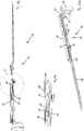
- the in the FIGS. 7 . 8th . 9 and 10 differs substantially from the first and second embodiments described above thereby; a counter toothing 59 is formed on an upper side of the scissors arm 17 facing the scissor arm 15, and a clamping part 61 which is arranged between the scissor arm 15 and the scissors arm 17 has a toothing 63 which can engage the counter toothing 59.
- the scissors link 17 is pivotally coupled to the scissors arm 15 at the first coupling point 23 with the scissors turret 19 and at the articulation point 21 and transversely to a rotational axis 75 of the articulation point 21.
- the scissor arm has a lateral counter-toothing 65 (see Fig. 8B ), which is opposite to a lateral toothing 67 of the clamping part.
- the clamping member 61 is elongate and largely U-shaped profile. At the top of the scissor arm 17 opposite side of the clamping part 61, the counter teeth 59 is formed. On one of the inner side surfaces of the clamping part 61, namely on the side surface, which transmits a force on the scissor arm 17 when closing the scissors fitting from the tilted position, the lateral toothing 67 is formed. When the counter teeth 59 and 65 are not engaged with the gears 63 and 67, the clamping member 61 and scissor arms 17 can move relative to each other along their longitudinal axes since the pin 45 is slidable in the slot 47 along the longitudinal axes.
- two elongated projections 69 (see Fig. 9A and 10C ), which are respectively arranged on opposite sides of the articulation point 21 in opposite end portions of the clamping part 61.
- the height of these elevations 69 corresponds approximately to the height of the lateral counter-toothing 65.
- the elevations 69 come into contact with the sides of the scissor arm 15 and are chamfered 71 on the sides of the scissor arm 15 and / or frontal bevels 73 on the elevations 69 in the direction of the scissor arm 17, ie Fig. 7 down, pressed.
- the clamping part 61 is displaced along the axis of rotation 75 at the articulation point 21, so that the toothing 63 comes into engagement with the counter toothing 59.
- the wing during rotation closing initially runs on its lower side on the frame and is thereby forcibly lifted and thus corrected in his position.
- the door is open and closed ( Fig. 9B . 10A, 10B 10C ) is the teeth 63 with the counter teeth 59 and possibly also the teeth 67 with the counter teeth 65 into engagement, so that at the time of closing from a rotationally open state, no shortening of the effective length of the scissors fitting 13 can take place.
- the scissors fitting 13 tense up instead.
- the wing (from the tilted position) is closed, first the toothing 67 engages in the counter-toothing 65, as already described, whereby the desired, shortened, effective length of the scissors fitting 13 is determined.
- the teeth 63 and the counter teeth 59 engage each other, is held by the ultimately achieved with fully closed wing, the effective length achieved.
- the effective length of the scissors fitting 13 is automatically set so that the wing does not run when closing from the rotationally opened state on the frame. A possibly occurring due to wear, unwanted, renewed lowering of the wing is compensated reliably by the invention when tilting automatically by further shortening the effective length of the scissors fitting 13.
- All three embodiments have in common that they achieve in a structurally simple manner, an automatic correction of a malposition of the wing relative to the frame by taking advantage of the fact that the wing is forced to close by the frame inevitably in a correct position, and by the inventive fitting arrangement 11 it allows that the effective length of the scissors fitting 13 when closing change, in particular can shorten, but then against renewed lengthening, in particular during the rotary opening of the wing, is blocked.
Landscapes
- Engineering & Computer Science (AREA)
- Mechanical Engineering (AREA)
- Hinges (AREA)
Priority Applications (3)
| Application Number | Priority Date | Filing Date | Title |
|---|---|---|---|
| EP16155733.5A EP3045637B1 (de) | 2014-01-31 | 2014-11-17 | Beschlaganordnung |
| PL14193491T PL2902575T3 (pl) | 2014-01-31 | 2014-11-17 | System okuciowy |
| PL16155733T PL3045637T3 (pl) | 2014-01-31 | 2014-11-17 | System okuciowy |
Applications Claiming Priority (1)
| Application Number | Priority Date | Filing Date | Title |
|---|---|---|---|
| DE102014101218.6A DE102014101218A1 (de) | 2014-01-31 | 2014-01-31 | Beschlaganordnung |
Related Child Applications (2)
| Application Number | Title | Priority Date | Filing Date |
|---|---|---|---|
| EP16155733.5A Division-Into EP3045637B1 (de) | 2014-01-31 | 2014-11-17 | Beschlaganordnung |
| EP16155733.5A Division EP3045637B1 (de) | 2014-01-31 | 2014-11-17 | Beschlaganordnung |
Publications (2)
| Publication Number | Publication Date |
|---|---|
| EP2902575A1 EP2902575A1 (de) | 2015-08-05 |
| EP2902575B1 true EP2902575B1 (de) | 2017-01-11 |
Family
ID=52006823
Family Applications (2)
| Application Number | Title | Priority Date | Filing Date |
|---|---|---|---|
| EP14193491.9A Active EP2902575B1 (de) | 2014-01-31 | 2014-11-17 | Beschlaganordnung |
| EP16155733.5A Active EP3045637B1 (de) | 2014-01-31 | 2014-11-17 | Beschlaganordnung |
Family Applications After (1)
| Application Number | Title | Priority Date | Filing Date |
|---|---|---|---|
| EP16155733.5A Active EP3045637B1 (de) | 2014-01-31 | 2014-11-17 | Beschlaganordnung |
Country Status (3)
| Country | Link |
|---|---|
| EP (2) | EP2902575B1 (pl) |
| DE (1) | DE102014101218A1 (pl) |
| PL (2) | PL3045637T3 (pl) |
Families Citing this family (3)
| Publication number | Priority date | Publication date | Assignee | Title |
|---|---|---|---|---|
| DE202016002166U1 (de) | 2016-04-07 | 2017-07-10 | Siegenia-Aubi Kg | Beschlaganordnung |
| DE102016108953A1 (de) * | 2016-05-13 | 2017-11-16 | Maco Technologie Gmbh | Beschlaganordnung |
| DE202023100930U1 (de) | 2023-02-28 | 2023-03-08 | Siegenia-Aubi Kg | Beschlaganordnung |
Family Cites Families (2)
| Publication number | Priority date | Publication date | Assignee | Title |
|---|---|---|---|---|
| DE7112124U (de) * | 1973-10-18 | Siegenia-Frank Kg | Ausstellvorrichtung fur Kipp Schwenkflügel von Fenstern, Türen od | |
| DE19718325C1 (de) * | 1997-04-30 | 1998-08-13 | Siegenia Frank Kg | Selbsttätig wirkende Justiervorrichtung |
-
2014
- 2014-01-31 DE DE102014101218.6A patent/DE102014101218A1/de not_active Withdrawn
- 2014-11-17 PL PL16155733T patent/PL3045637T3/pl unknown
- 2014-11-17 EP EP14193491.9A patent/EP2902575B1/de active Active
- 2014-11-17 PL PL14193491T patent/PL2902575T3/pl unknown
- 2014-11-17 EP EP16155733.5A patent/EP3045637B1/de active Active
Also Published As
| Publication number | Publication date |
|---|---|
| PL2902575T3 (pl) | 2017-07-31 |
| EP2902575A1 (de) | 2015-08-05 |
| EP3045637A1 (de) | 2016-07-20 |
| EP3045637B1 (de) | 2021-03-10 |
| DE102014101218A1 (de) | 2015-08-06 |
| PL3045637T3 (pl) | 2021-09-20 |
Similar Documents
| Publication | Publication Date | Title |
|---|---|---|
| EP3789571A1 (de) | Scharnier mit hebe-/senkmechanismus | |
| WO2018033221A1 (de) | Möbelscharnier | |
| EP2902575B1 (de) | Beschlaganordnung | |
| EP3034731B1 (de) | Beschlag für fenster und türen | |
| EP3175068B1 (de) | Beschlaganordnung | |
| EP3183408B1 (de) | Steuerelement für eine beschlaganordnung | |
| EP3524765A1 (de) | Absenkbare einbruchsicherung | |
| EP0723058B1 (de) | Bremse, insbesondere für einen Oberlichtflügel | |
| EP4187050B1 (de) | Befestigungseinrichtung für eine gebäudeverschlusseinrichtung, verfahren zum herstellen der befestigungseinrichtung sowie gebäudeverschlusseinrichtung | |
| EP1153187B1 (de) | Scharnier mit arretierung | |
| DE2658626B2 (de) | Schaltsperre für Treibstangenbeschläge | |
| EP2618698B1 (de) | Vorrichtung zur verstellung der neigung eines bewegbaren möbelteils und möbel | |
| EP3516143B1 (de) | Beschlaganordnung | |
| DE4023790A1 (de) | Scharnier zur gelenkigen verbindung zweier teilfluegel eines tuerfluegels | |
| EP3243989B1 (de) | Beschlaganordnung | |
| DE102014112072B4 (de) | Flügelheber | |
| DE2727585C2 (de) | Nachstellbares Lenker-Drehlager für Kipp-Schwenkfenster oder -türen | |
| EP0843063A1 (de) | Brems- und Feststellvorrichtung | |
| EP1659242B1 (de) | Türhalter | |
| DE202005009745U1 (de) | Beschlaganordnung | |
| DE2551316A1 (de) | Ausstellvorrichtung, insbesondere fuer wahlweisen links- oder rechtsanschlag fuer fluegel von tueren, fenstern o.dgl. | |
| DE202005012153U1 (de) | Profil/Bandsystem | |
| DE202007000136U1 (de) | Jalousie | |
| DE19601326C2 (de) | Ausstellvorrichtung für Drehkippflügel | |
| CH625305A5 (en) | Scissor mechanism for a wing of a window or door |
Legal Events
| Date | Code | Title | Description |
|---|---|---|---|
| PUAI | Public reference made under article 153(3) epc to a published international application that has entered the european phase |
Free format text: ORIGINAL CODE: 0009012 |
|
| 17P | Request for examination filed |
Effective date: 20141117 |
|
| AK | Designated contracting states |
Kind code of ref document: A1 Designated state(s): AL AT BE BG CH CY CZ DE DK EE ES FI FR GB GR HR HU IE IS IT LI LT LU LV MC MK MT NL NO PL PT RO RS SE SI SK SM TR |
|
| AX | Request for extension of the european patent |
Extension state: BA ME |
|
| 17P | Request for examination filed |
Effective date: 20160127 |
|
| RBV | Designated contracting states (corrected) |
Designated state(s): AL AT BE BG CH CY CZ DE DK EE ES FI FR GB GR HR HU IE IS IT LI LT LU LV MC MK MT NL NO PL PT RO RS SE SI SK SM TR |
|
| GRAP | Despatch of communication of intention to grant a patent |
Free format text: ORIGINAL CODE: EPIDOSNIGR1 |
|
| INTG | Intention to grant announced |
Effective date: 20160810 |
|
| GRAS | Grant fee paid |
Free format text: ORIGINAL CODE: EPIDOSNIGR3 |
|
| GRAA | (expected) grant |
Free format text: ORIGINAL CODE: 0009210 |
|
| STAA | Information on the status of an ep patent application or granted ep patent |
Free format text: STATUS: THE PATENT HAS BEEN GRANTED |
|
| AK | Designated contracting states |
Kind code of ref document: B1 Designated state(s): AL AT BE BG CH CY CZ DE DK EE ES FI FR GB GR HR HU IE IS IT LI LT LU LV MC MK MT NL NO PL PT RO RS SE SI SK SM TR |
|
| REG | Reference to a national code |
Ref country code: GB Ref legal event code: FG4D Free format text: NOT ENGLISH |
|
| REG | Reference to a national code |
Ref country code: CH Ref legal event code: EP |
|
| REG | Reference to a national code |
Ref country code: AT Ref legal event code: REF Ref document number: 861463 Country of ref document: AT Kind code of ref document: T Effective date: 20170115 |
|
| REG | Reference to a national code |
Ref country code: IE Ref legal event code: FG4D Free format text: LANGUAGE OF EP DOCUMENT: GERMAN |
|
| REG | Reference to a national code |
Ref country code: DE Ref legal event code: R096 Ref document number: 502014002473 Country of ref document: DE |
|
| REG | Reference to a national code |
Ref country code: LT Ref legal event code: MG4D |
|
| REG | Reference to a national code |
Ref country code: NL Ref legal event code: MP Effective date: 20170111 |
|
| PG25 | Lapsed in a contracting state [announced via postgrant information from national office to epo] |
Ref country code: NL Free format text: LAPSE BECAUSE OF FAILURE TO SUBMIT A TRANSLATION OF THE DESCRIPTION OR TO PAY THE FEE WITHIN THE PRESCRIBED TIME-LIMIT Effective date: 20170111 |
|
| PG25 | Lapsed in a contracting state [announced via postgrant information from national office to epo] |
Ref country code: GR Free format text: LAPSE BECAUSE OF FAILURE TO SUBMIT A TRANSLATION OF THE DESCRIPTION OR TO PAY THE FEE WITHIN THE PRESCRIBED TIME-LIMIT Effective date: 20170412 Ref country code: FI Free format text: LAPSE BECAUSE OF FAILURE TO SUBMIT A TRANSLATION OF THE DESCRIPTION OR TO PAY THE FEE WITHIN THE PRESCRIBED TIME-LIMIT Effective date: 20170111 Ref country code: NO Free format text: LAPSE BECAUSE OF FAILURE TO SUBMIT A TRANSLATION OF THE DESCRIPTION OR TO PAY THE FEE WITHIN THE PRESCRIBED TIME-LIMIT Effective date: 20170411 Ref country code: IS Free format text: LAPSE BECAUSE OF FAILURE TO SUBMIT A TRANSLATION OF THE DESCRIPTION OR TO PAY THE FEE WITHIN THE PRESCRIBED TIME-LIMIT Effective date: 20170511 Ref country code: LT Free format text: LAPSE BECAUSE OF FAILURE TO SUBMIT A TRANSLATION OF THE DESCRIPTION OR TO PAY THE FEE WITHIN THE PRESCRIBED TIME-LIMIT Effective date: 20170111 Ref country code: HR Free format text: LAPSE BECAUSE OF FAILURE TO SUBMIT A TRANSLATION OF THE DESCRIPTION OR TO PAY THE FEE WITHIN THE PRESCRIBED TIME-LIMIT Effective date: 20170111 |
|
| PG25 | Lapsed in a contracting state [announced via postgrant information from national office to epo] |
Ref country code: SE Free format text: LAPSE BECAUSE OF FAILURE TO SUBMIT A TRANSLATION OF THE DESCRIPTION OR TO PAY THE FEE WITHIN THE PRESCRIBED TIME-LIMIT Effective date: 20170111 Ref country code: RS Free format text: LAPSE BECAUSE OF FAILURE TO SUBMIT A TRANSLATION OF THE DESCRIPTION OR TO PAY THE FEE WITHIN THE PRESCRIBED TIME-LIMIT Effective date: 20170111 Ref country code: ES Free format text: LAPSE BECAUSE OF FAILURE TO SUBMIT A TRANSLATION OF THE DESCRIPTION OR TO PAY THE FEE WITHIN THE PRESCRIBED TIME-LIMIT Effective date: 20170111 Ref country code: BG Free format text: LAPSE BECAUSE OF FAILURE TO SUBMIT A TRANSLATION OF THE DESCRIPTION OR TO PAY THE FEE WITHIN THE PRESCRIBED TIME-LIMIT Effective date: 20170411 Ref country code: PT Free format text: LAPSE BECAUSE OF FAILURE TO SUBMIT A TRANSLATION OF THE DESCRIPTION OR TO PAY THE FEE WITHIN THE PRESCRIBED TIME-LIMIT Effective date: 20170511 Ref country code: LV Free format text: LAPSE BECAUSE OF FAILURE TO SUBMIT A TRANSLATION OF THE DESCRIPTION OR TO PAY THE FEE WITHIN THE PRESCRIBED TIME-LIMIT Effective date: 20170111 |
|
| REG | Reference to a national code |
Ref country code: DE Ref legal event code: R097 Ref document number: 502014002473 Country of ref document: DE |
|
| PG25 | Lapsed in a contracting state [announced via postgrant information from national office to epo] |
Ref country code: SK Free format text: LAPSE BECAUSE OF FAILURE TO SUBMIT A TRANSLATION OF THE DESCRIPTION OR TO PAY THE FEE WITHIN THE PRESCRIBED TIME-LIMIT Effective date: 20170111 Ref country code: EE Free format text: LAPSE BECAUSE OF FAILURE TO SUBMIT A TRANSLATION OF THE DESCRIPTION OR TO PAY THE FEE WITHIN THE PRESCRIBED TIME-LIMIT Effective date: 20170111 Ref country code: RO Free format text: LAPSE BECAUSE OF FAILURE TO SUBMIT A TRANSLATION OF THE DESCRIPTION OR TO PAY THE FEE WITHIN THE PRESCRIBED TIME-LIMIT Effective date: 20170111 |
|
| PLBE | No opposition filed within time limit |
Free format text: ORIGINAL CODE: 0009261 |
|
| STAA | Information on the status of an ep patent application or granted ep patent |
Free format text: STATUS: NO OPPOSITION FILED WITHIN TIME LIMIT |
|
| PG25 | Lapsed in a contracting state [announced via postgrant information from national office to epo] |
Ref country code: SM Free format text: LAPSE BECAUSE OF FAILURE TO SUBMIT A TRANSLATION OF THE DESCRIPTION OR TO PAY THE FEE WITHIN THE PRESCRIBED TIME-LIMIT Effective date: 20170111 Ref country code: DK Free format text: LAPSE BECAUSE OF FAILURE TO SUBMIT A TRANSLATION OF THE DESCRIPTION OR TO PAY THE FEE WITHIN THE PRESCRIBED TIME-LIMIT Effective date: 20170111 |
|
| 26N | No opposition filed |
Effective date: 20171012 |
|
| REG | Reference to a national code |
Ref country code: FR Ref legal event code: PLFP Year of fee payment: 4 |
|
| PGFP | Annual fee paid to national office [announced via postgrant information from national office to epo] |
Ref country code: CZ Payment date: 20171228 Year of fee payment: 4 Ref country code: TR Payment date: 20171215 Year of fee payment: 4 |
|
| PG25 | Lapsed in a contracting state [announced via postgrant information from national office to epo] |
Ref country code: SI Free format text: LAPSE BECAUSE OF FAILURE TO SUBMIT A TRANSLATION OF THE DESCRIPTION OR TO PAY THE FEE WITHIN THE PRESCRIBED TIME-LIMIT Effective date: 20170111 |
|
| PG25 | Lapsed in a contracting state [announced via postgrant information from national office to epo] |
Ref country code: MC Free format text: LAPSE BECAUSE OF FAILURE TO SUBMIT A TRANSLATION OF THE DESCRIPTION OR TO PAY THE FEE WITHIN THE PRESCRIBED TIME-LIMIT Effective date: 20170111 |
|
| PG25 | Lapsed in a contracting state [announced via postgrant information from national office to epo] |
Ref country code: LI Free format text: LAPSE BECAUSE OF NON-PAYMENT OF DUE FEES Effective date: 20171130 Ref country code: CH Free format text: LAPSE BECAUSE OF NON-PAYMENT OF DUE FEES Effective date: 20171130 |
|
| PG25 | Lapsed in a contracting state [announced via postgrant information from national office to epo] |
Ref country code: LU Free format text: LAPSE BECAUSE OF NON-PAYMENT OF DUE FEES Effective date: 20171117 |
|
| REG | Reference to a national code |
Ref country code: BE Ref legal event code: MM Effective date: 20171130 |
|
| REG | Reference to a national code |
Ref country code: IE Ref legal event code: MM4A |
|
| PG25 | Lapsed in a contracting state [announced via postgrant information from national office to epo] |
Ref country code: MT Free format text: LAPSE BECAUSE OF FAILURE TO SUBMIT A TRANSLATION OF THE DESCRIPTION OR TO PAY THE FEE WITHIN THE PRESCRIBED TIME-LIMIT Effective date: 20170111 |
|
| PG25 | Lapsed in a contracting state [announced via postgrant information from national office to epo] |
Ref country code: IE Free format text: LAPSE BECAUSE OF NON-PAYMENT OF DUE FEES Effective date: 20171117 |
|
| PG25 | Lapsed in a contracting state [announced via postgrant information from national office to epo] |
Ref country code: BE Free format text: LAPSE BECAUSE OF NON-PAYMENT OF DUE FEES Effective date: 20171130 |
|
| PGFP | Annual fee paid to national office [announced via postgrant information from national office to epo] |
Ref country code: PL Payment date: 20190110 Year of fee payment: 5 |
|
| PG25 | Lapsed in a contracting state [announced via postgrant information from national office to epo] |
Ref country code: HU Free format text: LAPSE BECAUSE OF FAILURE TO SUBMIT A TRANSLATION OF THE DESCRIPTION OR TO PAY THE FEE WITHIN THE PRESCRIBED TIME-LIMIT; INVALID AB INITIO Effective date: 20141117 |
|
| GBPC | Gb: european patent ceased through non-payment of renewal fee |
Effective date: 20181117 |
|
| PG25 | Lapsed in a contracting state [announced via postgrant information from national office to epo] |
Ref country code: CZ Free format text: LAPSE BECAUSE OF NON-PAYMENT OF DUE FEES Effective date: 20181117 |
|
| PG25 | Lapsed in a contracting state [announced via postgrant information from national office to epo] |
Ref country code: CY Free format text: LAPSE BECAUSE OF FAILURE TO SUBMIT A TRANSLATION OF THE DESCRIPTION OR TO PAY THE FEE WITHIN THE PRESCRIBED TIME-LIMIT Effective date: 20170111 |
|
| PG25 | Lapsed in a contracting state [announced via postgrant information from national office to epo] |
Ref country code: MK Free format text: LAPSE BECAUSE OF FAILURE TO SUBMIT A TRANSLATION OF THE DESCRIPTION OR TO PAY THE FEE WITHIN THE PRESCRIBED TIME-LIMIT Effective date: 20170111 |
|
| PG25 | Lapsed in a contracting state [announced via postgrant information from national office to epo] |
Ref country code: GB Free format text: LAPSE BECAUSE OF NON-PAYMENT OF DUE FEES Effective date: 20181117 |
|
| PG25 | Lapsed in a contracting state [announced via postgrant information from national office to epo] |
Ref country code: AL Free format text: LAPSE BECAUSE OF FAILURE TO SUBMIT A TRANSLATION OF THE DESCRIPTION OR TO PAY THE FEE WITHIN THE PRESCRIBED TIME-LIMIT Effective date: 20170111 |
|
| PG25 | Lapsed in a contracting state [announced via postgrant information from national office to epo] |
Ref country code: PL Free format text: LAPSE BECAUSE OF NON-PAYMENT OF DUE FEES Effective date: 20191117 |
|
| PG25 | Lapsed in a contracting state [announced via postgrant information from national office to epo] |
Ref country code: TR Free format text: LAPSE BECAUSE OF NON-PAYMENT OF DUE FEES Effective date: 20181117 |
|
| PGFP | Annual fee paid to national office [announced via postgrant information from national office to epo] |
Ref country code: DE Payment date: 20251119 Year of fee payment: 12 |
|
| PGFP | Annual fee paid to national office [announced via postgrant information from national office to epo] |
Ref country code: AT Payment date: 20251120 Year of fee payment: 12 |
|
| PGFP | Annual fee paid to national office [announced via postgrant information from national office to epo] |
Ref country code: IT Payment date: 20251125 Year of fee payment: 12 |
|
| PGFP | Annual fee paid to national office [announced via postgrant information from national office to epo] |
Ref country code: FR Payment date: 20251125 Year of fee payment: 12 |