EP2899574B1 - Heat ray cutting film and method for producing same, and laminated glass and heat ray cutting member - Google Patents
Heat ray cutting film and method for producing same, and laminated glass and heat ray cutting member Download PDFInfo
- Publication number
- EP2899574B1 EP2899574B1 EP13838930.9A EP13838930A EP2899574B1 EP 2899574 B1 EP2899574 B1 EP 2899574B1 EP 13838930 A EP13838930 A EP 13838930A EP 2899574 B1 EP2899574 B1 EP 2899574B1
- Authority
- EP
- European Patent Office
- Prior art keywords
- light reflecting
- reflecting layer
- layer
- heat ray
- liquid crystal
- Prior art date
- Legal status (The legal status is an assumption and is not a legal conclusion. Google has not performed a legal analysis and makes no representation as to the accuracy of the status listed.)
- Active
Links
- 238000005520 cutting process Methods 0.000 title claims description 129
- 239000005340 laminated glass Substances 0.000 title claims description 40
- 238000004519 manufacturing process Methods 0.000 title description 30
- 239000010410 layer Substances 0.000 claims description 465
- 239000007788 liquid Substances 0.000 claims description 186
- 239000000758 substrate Substances 0.000 claims description 100
- 230000003098 cholesteric effect Effects 0.000 claims description 90
- 239000011521 glass Substances 0.000 claims description 81
- 150000001875 compounds Chemical class 0.000 claims description 77
- 239000004973 liquid crystal related substance Substances 0.000 claims description 64
- 229910001930 tungsten oxide Inorganic materials 0.000 claims description 52
- 238000000034 method Methods 0.000 claims description 51
- QGLKJKCYBOYXKC-UHFFFAOYSA-N nonaoxidotritungsten Chemical compound O=[W]1(=O)O[W](=O)(=O)O[W](=O)(=O)O1 QGLKJKCYBOYXKC-UHFFFAOYSA-N 0.000 claims description 49
- 239000000203 mixture Substances 0.000 claims description 44
- 239000011859 microparticle Substances 0.000 claims description 37
- 239000002131 composite material Substances 0.000 claims description 29
- 229920005989 resin Polymers 0.000 claims description 29
- 239000011347 resin Substances 0.000 claims description 29
- 239000004986 Cholesteric liquid crystals (ChLC) Substances 0.000 claims description 24
- 238000006243 chemical reaction Methods 0.000 claims description 20
- 229910052792 caesium Inorganic materials 0.000 claims description 19
- 238000002310 reflectometry Methods 0.000 claims description 15
- 238000001035 drying Methods 0.000 claims description 12
- 239000002245 particle Substances 0.000 claims description 7
- 230000002250 progressing effect Effects 0.000 claims description 4
- 229910052742 iron Inorganic materials 0.000 claims description 3
- 229920005992 thermoplastic resin Polymers 0.000 claims description 3
- 229910052718 tin Inorganic materials 0.000 claims description 3
- 229910052791 calcium Inorganic materials 0.000 claims description 2
- 229910052738 indium Inorganic materials 0.000 claims description 2
- 229920003023 plastic Polymers 0.000 claims description 2
- 239000004033 plastic Substances 0.000 claims description 2
- 229910052700 potassium Inorganic materials 0.000 claims description 2
- 229910052701 rubidium Inorganic materials 0.000 claims description 2
- 229910052708 sodium Inorganic materials 0.000 claims description 2
- 229910052712 strontium Inorganic materials 0.000 claims description 2
- 239000002356 single layer Substances 0.000 claims 2
- 239000010408 film Substances 0.000 description 225
- 239000000463 material Substances 0.000 description 75
- 230000000052 comparative effect Effects 0.000 description 29
- 239000006096 absorbing agent Substances 0.000 description 26
- 238000002834 transmittance Methods 0.000 description 25
- 239000003795 chemical substances by application Substances 0.000 description 23
- 238000004040 coloring Methods 0.000 description 22
- 239000000975 dye Substances 0.000 description 19
- -1 tungsten oxide compound Chemical class 0.000 description 19
- 239000005268 rod-like liquid crystal Substances 0.000 description 18
- TVFDJXOCXUVLDH-UHFFFAOYSA-N caesium atom Chemical compound [Cs] TVFDJXOCXUVLDH-UHFFFAOYSA-N 0.000 description 17
- 239000000049 pigment Substances 0.000 description 16
- 229920000642 polymer Polymers 0.000 description 16
- UWCWUCKPEYNDNV-LBPRGKRZSA-N 2,6-dimethyl-n-[[(2s)-pyrrolidin-2-yl]methyl]aniline Chemical compound CC1=CC=CC(C)=C1NC[C@H]1NCCC1 UWCWUCKPEYNDNV-LBPRGKRZSA-N 0.000 description 15
- 238000010521 absorption reaction Methods 0.000 description 14
- 238000003475 lamination Methods 0.000 description 14
- 230000015572 biosynthetic process Effects 0.000 description 12
- 239000004372 Polyvinyl alcohol Substances 0.000 description 11
- 230000001070 adhesive effect Effects 0.000 description 11
- 238000001723 curing Methods 0.000 description 11
- 238000010438 heat treatment Methods 0.000 description 11
- 229920002451 polyvinyl alcohol Polymers 0.000 description 11
- 239000002904 solvent Substances 0.000 description 11
- 238000006116 polymerization reaction Methods 0.000 description 10
- ZWEHNKRNPOVVGH-UHFFFAOYSA-N 2-Butanone Chemical compound CCC(C)=O ZWEHNKRNPOVVGH-UHFFFAOYSA-N 0.000 description 9
- 239000011248 coating agent Substances 0.000 description 9
- 238000000576 coating method Methods 0.000 description 9
- 229910052751 metal Inorganic materials 0.000 description 9
- 239000002184 metal Substances 0.000 description 9
- 230000003287 optical effect Effects 0.000 description 9
- 229920002037 poly(vinyl butyral) polymer Polymers 0.000 description 9
- 229920006254 polymer film Polymers 0.000 description 9
- 238000002360 preparation method Methods 0.000 description 9
- 239000000047 product Substances 0.000 description 9
- 239000000654 additive Substances 0.000 description 8
- 239000003112 inhibitor Substances 0.000 description 8
- 239000000126 substance Substances 0.000 description 8
- 125000001424 substituent group Chemical group 0.000 description 8
- 239000000853 adhesive Substances 0.000 description 7
- 125000004432 carbon atom Chemical group C* 0.000 description 7
- 238000010030 laminating Methods 0.000 description 7
- 229910044991 metal oxide Inorganic materials 0.000 description 7
- 150000004706 metal oxides Chemical class 0.000 description 7
- 239000003505 polymerization initiator Substances 0.000 description 7
- 230000008569 process Effects 0.000 description 7
- PPBRXRYQALVLMV-UHFFFAOYSA-N Styrene Chemical compound C=CC1=CC=CC=C1 PPBRXRYQALVLMV-UHFFFAOYSA-N 0.000 description 6
- 230000006866 deterioration Effects 0.000 description 6
- 230000001747 exhibiting effect Effects 0.000 description 6
- 239000004611 light stabiliser Substances 0.000 description 6
- 125000005647 linker group Chemical group 0.000 description 6
- 239000002994 raw material Substances 0.000 description 6
- 230000000996 additive effect Effects 0.000 description 5
- 125000003118 aryl group Chemical group 0.000 description 5
- 239000012298 atmosphere Substances 0.000 description 5
- QVGXLLKOCUKJST-UHFFFAOYSA-N atomic oxygen Chemical compound [O] QVGXLLKOCUKJST-UHFFFAOYSA-N 0.000 description 5
- 238000001816 cooling Methods 0.000 description 5
- 229920001577 copolymer Polymers 0.000 description 5
- 230000000694 effects Effects 0.000 description 5
- 230000003647 oxidation Effects 0.000 description 5
- 238000007254 oxidation reaction Methods 0.000 description 5
- 229910052760 oxygen Inorganic materials 0.000 description 5
- 239000001301 oxygen Substances 0.000 description 5
- IEQIEDJGQAUEQZ-UHFFFAOYSA-N phthalocyanine Chemical compound N1C(N=C2C3=CC=CC=C3C(N=C3C4=CC=CC=C4C(=N4)N3)=N2)=C(C=CC=C2)C2=C1N=C1C2=CC=CC=C2C4=N1 IEQIEDJGQAUEQZ-UHFFFAOYSA-N 0.000 description 5
- 238000001228 spectrum Methods 0.000 description 5
- 230000007704 transition Effects 0.000 description 5
- 229920002799 BoPET Polymers 0.000 description 4
- 229920002284 Cellulose triacetate Polymers 0.000 description 4
- KFZMGEQAYNKOFK-UHFFFAOYSA-N Isopropanol Chemical compound CC(C)O KFZMGEQAYNKOFK-UHFFFAOYSA-N 0.000 description 4
- NNLVGZFZQQXQNW-ADJNRHBOSA-N [(2r,3r,4s,5r,6s)-4,5-diacetyloxy-3-[(2s,3r,4s,5r,6r)-3,4,5-triacetyloxy-6-(acetyloxymethyl)oxan-2-yl]oxy-6-[(2r,3r,4s,5r,6s)-4,5,6-triacetyloxy-2-(acetyloxymethyl)oxan-3-yl]oxyoxan-2-yl]methyl acetate Chemical compound O([C@@H]1O[C@@H]([C@H]([C@H](OC(C)=O)[C@H]1OC(C)=O)O[C@H]1[C@@H]([C@@H](OC(C)=O)[C@H](OC(C)=O)[C@@H](COC(C)=O)O1)OC(C)=O)COC(=O)C)[C@@H]1[C@@H](COC(C)=O)O[C@@H](OC(C)=O)[C@H](OC(C)=O)[C@H]1OC(C)=O NNLVGZFZQQXQNW-ADJNRHBOSA-N 0.000 description 4
- 238000004364 calculation method Methods 0.000 description 4
- 229910052799 carbon Inorganic materials 0.000 description 4
- 238000010276 construction Methods 0.000 description 4
- 239000013078 crystal Substances 0.000 description 4
- 229920000515 polycarbonate Polymers 0.000 description 4
- 239000004417 polycarbonate Substances 0.000 description 4
- 238000012545 processing Methods 0.000 description 4
- 238000000411 transmission spectrum Methods 0.000 description 4
- WFKWXMTUELFFGS-UHFFFAOYSA-N tungsten Chemical compound [W] WFKWXMTUELFFGS-UHFFFAOYSA-N 0.000 description 4
- 229910052721 tungsten Inorganic materials 0.000 description 4
- 239000010937 tungsten Substances 0.000 description 4
- YMWUJEATGCHHMB-UHFFFAOYSA-N Dichloromethane Chemical compound ClCCl YMWUJEATGCHHMB-UHFFFAOYSA-N 0.000 description 3
- XEKOWRVHYACXOJ-UHFFFAOYSA-N Ethyl acetate Chemical compound CCOC(C)=O XEKOWRVHYACXOJ-UHFFFAOYSA-N 0.000 description 3
- 108010010803 Gelatin Proteins 0.000 description 3
- GWEVSGVZZGPLCZ-UHFFFAOYSA-N Titan oxide Chemical compound O=[Ti]=O GWEVSGVZZGPLCZ-UHFFFAOYSA-N 0.000 description 3
- YXFVVABEGXRONW-UHFFFAOYSA-N Toluene Chemical compound CC1=CC=CC=C1 YXFVVABEGXRONW-UHFFFAOYSA-N 0.000 description 3
- 239000011358 absorbing material Substances 0.000 description 3
- NIXOWILDQLNWCW-UHFFFAOYSA-N acrylic acid group Chemical group C(C=C)(=O)O NIXOWILDQLNWCW-UHFFFAOYSA-N 0.000 description 3
- 125000002723 alicyclic group Chemical group 0.000 description 3
- 125000000217 alkyl group Chemical group 0.000 description 3
- 125000002947 alkylene group Chemical group 0.000 description 3
- 229940125904 compound 1 Drugs 0.000 description 3
- 229940125782 compound 2 Drugs 0.000 description 3
- 230000007547 defect Effects 0.000 description 3
- 229920000159 gelatin Polymers 0.000 description 3
- 239000008273 gelatin Substances 0.000 description 3
- 235000019322 gelatine Nutrition 0.000 description 3
- 235000011852 gelatine desserts Nutrition 0.000 description 3
- 125000004435 hydrogen atom Chemical group [H]* 0.000 description 3
- 230000001965 increasing effect Effects 0.000 description 3
- 239000003999 initiator Substances 0.000 description 3
- XEEYBQQBJWHFJM-UHFFFAOYSA-N iron Substances [Fe] XEEYBQQBJWHFJM-UHFFFAOYSA-N 0.000 description 3
- 238000002156 mixing Methods 0.000 description 3
- PXHVJJICTQNCMI-UHFFFAOYSA-N nickel Substances [Ni] PXHVJJICTQNCMI-UHFFFAOYSA-N 0.000 description 3
- 239000003960 organic solvent Substances 0.000 description 3
- 229920000728 polyester Polymers 0.000 description 3
- 229920000139 polyethylene terephthalate Polymers 0.000 description 3
- 239000005020 polyethylene terephthalate Substances 0.000 description 3
- 239000002952 polymeric resin Substances 0.000 description 3
- 229920000098 polyolefin Polymers 0.000 description 3
- 229920000915 polyvinyl chloride Polymers 0.000 description 3
- 239000004800 polyvinyl chloride Substances 0.000 description 3
- VYPSYNLAJGMNEJ-UHFFFAOYSA-N silicon dioxide Inorganic materials O=[Si]=O VYPSYNLAJGMNEJ-UHFFFAOYSA-N 0.000 description 3
- 229920003002 synthetic resin Polymers 0.000 description 3
- LDXJRKWFNNFDSA-UHFFFAOYSA-N 2-(2,4,6,7-tetrahydrotriazolo[4,5-c]pyridin-5-yl)-1-[4-[2-[[3-(trifluoromethoxy)phenyl]methylamino]pyrimidin-5-yl]piperazin-1-yl]ethanone Chemical compound C1CN(CC2=NNN=C21)CC(=O)N3CCN(CC3)C4=CN=C(N=C4)NCC5=CC(=CC=C5)OC(F)(F)F LDXJRKWFNNFDSA-UHFFFAOYSA-N 0.000 description 2
- JQMFQLVAJGZSQS-UHFFFAOYSA-N 2-[4-[2-(2,3-dihydro-1H-inden-2-ylamino)pyrimidin-5-yl]piperazin-1-yl]-N-(2-oxo-3H-1,3-benzoxazol-6-yl)acetamide Chemical compound C1C(CC2=CC=CC=C12)NC1=NC=C(C=N1)N1CCN(CC1)CC(=O)NC1=CC2=C(NC(O2)=O)C=C1 JQMFQLVAJGZSQS-UHFFFAOYSA-N 0.000 description 2
- CCTFMNIEFHGTDU-UHFFFAOYSA-N 3-methoxypropyl acetate Chemical compound COCCCOC(C)=O CCTFMNIEFHGTDU-UHFFFAOYSA-N 0.000 description 2
- CSCPPACGZOOCGX-UHFFFAOYSA-N Acetone Chemical compound CC(C)=O CSCPPACGZOOCGX-UHFFFAOYSA-N 0.000 description 2
- NIXOWILDQLNWCW-UHFFFAOYSA-M Acrylate Chemical compound [O-]C(=O)C=C NIXOWILDQLNWCW-UHFFFAOYSA-M 0.000 description 2
- 229920000178 Acrylic resin Polymers 0.000 description 2
- 239000004925 Acrylic resin Substances 0.000 description 2
- 229920002134 Carboxymethyl cellulose Polymers 0.000 description 2
- HEDRZPFGACZZDS-UHFFFAOYSA-N Chloroform Chemical compound ClC(Cl)Cl HEDRZPFGACZZDS-UHFFFAOYSA-N 0.000 description 2
- YCKRFDGAMUMZLT-UHFFFAOYSA-N Fluorine atom Chemical compound [F] YCKRFDGAMUMZLT-UHFFFAOYSA-N 0.000 description 2
- 239000004988 Nematic liquid crystal Substances 0.000 description 2
- 239000004698 Polyethylene Substances 0.000 description 2
- 239000004743 Polypropylene Substances 0.000 description 2
- XLOMVQKBTHCTTD-UHFFFAOYSA-N Zinc monoxide Chemical compound [Zn]=O XLOMVQKBTHCTTD-UHFFFAOYSA-N 0.000 description 2
- MCMNRKCIXSYSNV-UHFFFAOYSA-N Zirconium dioxide Chemical compound O=[Zr]=O MCMNRKCIXSYSNV-UHFFFAOYSA-N 0.000 description 2
- 239000002250 absorbent Substances 0.000 description 2
- 230000002745 absorbent Effects 0.000 description 2
- DZBUGLKDJFMEHC-UHFFFAOYSA-N acridine Chemical compound C1=CC=CC2=CC3=CC=CC=C3N=C21 DZBUGLKDJFMEHC-UHFFFAOYSA-N 0.000 description 2
- 125000004450 alkenylene group Chemical group 0.000 description 2
- HUVXQFBFIFIDDU-UHFFFAOYSA-N aluminum phthalocyanine Chemical compound [Al+3].C12=CC=CC=C2C(N=C2[N-]C(C3=CC=CC=C32)=N2)=NC1=NC([C]1C=CC=CC1=1)=NC=1N=C1[C]3C=CC=CC3=C2[N-]1 HUVXQFBFIFIDDU-UHFFFAOYSA-N 0.000 description 2
- RDOXTESZEPMUJZ-UHFFFAOYSA-N anisole Chemical compound COC1=CC=CC=C1 RDOXTESZEPMUJZ-UHFFFAOYSA-N 0.000 description 2
- 125000004069 aziridinyl group Chemical group 0.000 description 2
- 230000005540 biological transmission Effects 0.000 description 2
- OCWYEMOEOGEQAN-UHFFFAOYSA-N bumetrizole Chemical compound CC(C)(C)C1=CC(C)=CC(N2N=C3C=C(Cl)C=CC3=N2)=C1O OCWYEMOEOGEQAN-UHFFFAOYSA-N 0.000 description 2
- 239000001768 carboxy methyl cellulose Substances 0.000 description 2
- 235000010948 carboxy methyl cellulose Nutrition 0.000 description 2
- 239000008112 carboxymethyl-cellulose Substances 0.000 description 2
- 150000001768 cations Chemical class 0.000 description 2
- 230000008859 change Effects 0.000 description 2
- XCJYREBRNVKWGJ-UHFFFAOYSA-N copper(II) phthalocyanine Chemical compound [Cu+2].C12=CC=CC=C2C(N=C2[N-]C(C3=CC=CC=C32)=N2)=NC1=NC([C]1C=CC=CC1=1)=NC=1N=C1[C]3C=CC=CC3=C2[N-]1 XCJYREBRNVKWGJ-UHFFFAOYSA-N 0.000 description 2
- ZYGHJZDHTFUPRJ-UHFFFAOYSA-N coumarin Chemical compound C1=CC=C2OC(=O)C=CC2=C1 ZYGHJZDHTFUPRJ-UHFFFAOYSA-N 0.000 description 2
- JHIVVAPYMSGYDF-UHFFFAOYSA-N cyclohexanone Chemical compound O=C1CCCCC1 JHIVVAPYMSGYDF-UHFFFAOYSA-N 0.000 description 2
- 229920001971 elastomer Polymers 0.000 description 2
- 125000003700 epoxy group Chemical group 0.000 description 2
- 229910052731 fluorine Inorganic materials 0.000 description 2
- 239000011737 fluorine Substances 0.000 description 2
- 230000004927 fusion Effects 0.000 description 2
- 238000007756 gravure coating Methods 0.000 description 2
- 230000003301 hydrolyzing effect Effects 0.000 description 2
- 235000019239 indanthrene blue RS Nutrition 0.000 description 2
- AMGQUBHHOARCQH-UHFFFAOYSA-N indium;oxotin Chemical compound [In].[Sn]=O AMGQUBHHOARCQH-UHFFFAOYSA-N 0.000 description 2
- 229910010272 inorganic material Inorganic materials 0.000 description 2
- 230000001678 irradiating effect Effects 0.000 description 2
- 239000000178 monomer Substances 0.000 description 2
- 230000007935 neutral effect Effects 0.000 description 2
- 229910052759 nickel Inorganic materials 0.000 description 2
- 150000002894 organic compounds Chemical class 0.000 description 2
- 230000002093 peripheral effect Effects 0.000 description 2
- 229920003229 poly(methyl methacrylate) Polymers 0.000 description 2
- 229920001225 polyester resin Polymers 0.000 description 2
- 229920000573 polyethylene Polymers 0.000 description 2
- 239000004848 polyfunctional curative Substances 0.000 description 2
- 229920001721 polyimide Polymers 0.000 description 2
- 239000004926 polymethyl methacrylate Substances 0.000 description 2
- LLHKCFNBLRBOGN-UHFFFAOYSA-N propylene glycol methyl ether acetate Chemical compound COCC(C)OC(C)=O LLHKCFNBLRBOGN-UHFFFAOYSA-N 0.000 description 2
- 239000005060 rubber Substances 0.000 description 2
- 239000011135 tin Substances 0.000 description 2
- 229920002554 vinyl polymer Polymers 0.000 description 2
- XLYOFNOQVPJJNP-UHFFFAOYSA-N water Substances O XLYOFNOQVPJJNP-UHFFFAOYSA-N 0.000 description 2
- 230000037303 wrinkles Effects 0.000 description 2
- QGKMIGUHVLGJBR-UHFFFAOYSA-M (4z)-1-(3-methylbutyl)-4-[[1-(3-methylbutyl)quinolin-1-ium-4-yl]methylidene]quinoline;iodide Chemical compound [I-].C12=CC=CC=C2N(CCC(C)C)C=CC1=CC1=CC=[N+](CCC(C)C)C2=CC=CC=C12 QGKMIGUHVLGJBR-UHFFFAOYSA-M 0.000 description 1
- YLVACWCCJCZITJ-UHFFFAOYSA-N 1,4-dioxane-2,3-diol Chemical compound OC1OCCOC1O YLVACWCCJCZITJ-UHFFFAOYSA-N 0.000 description 1
- OHVLMTFVQDZYHP-UHFFFAOYSA-N 1-(2,4,6,7-tetrahydrotriazolo[4,5-c]pyridin-5-yl)-2-[4-[2-[[3-(trifluoromethoxy)phenyl]methylamino]pyrimidin-5-yl]piperazin-1-yl]ethanone Chemical compound N1N=NC=2CN(CCC=21)C(CN1CCN(CC1)C=1C=NC(=NC=1)NCC1=CC(=CC=C1)OC(F)(F)F)=O OHVLMTFVQDZYHP-UHFFFAOYSA-N 0.000 description 1
- AUXIEQKHXAYAHG-UHFFFAOYSA-N 1-phenylcyclohexane-1-carbonitrile Chemical class C=1C=CC=CC=1C1(C#N)CCCCC1 AUXIEQKHXAYAHG-UHFFFAOYSA-N 0.000 description 1
- OOLUVSIJOMLOCB-UHFFFAOYSA-N 1633-22-3 Chemical compound C1CC(C=C2)=CC=C2CCC2=CC=C1C=C2 OOLUVSIJOMLOCB-UHFFFAOYSA-N 0.000 description 1
- RNFJDJUURJAICM-UHFFFAOYSA-N 2,2,4,4,6,6-hexaphenoxy-1,3,5-triaza-2$l^{5},4$l^{5},6$l^{5}-triphosphacyclohexa-1,3,5-triene Chemical compound N=1P(OC=2C=CC=CC=2)(OC=2C=CC=CC=2)=NP(OC=2C=CC=CC=2)(OC=2C=CC=CC=2)=NP=1(OC=1C=CC=CC=1)OC1=CC=CC=C1 RNFJDJUURJAICM-UHFFFAOYSA-N 0.000 description 1
- SMZOUWXMTYCWNB-UHFFFAOYSA-N 2-(2-methoxy-5-methylphenyl)ethanamine Chemical compound COC1=CC=C(C)C=C1CCN SMZOUWXMTYCWNB-UHFFFAOYSA-N 0.000 description 1
- IHCCLXNEEPMSIO-UHFFFAOYSA-N 2-[4-[2-(2,3-dihydro-1H-inden-2-ylamino)pyrimidin-5-yl]piperidin-1-yl]-1-(2,4,6,7-tetrahydrotriazolo[4,5-c]pyridin-5-yl)ethanone Chemical compound C1C(CC2=CC=CC=C12)NC1=NC=C(C=N1)C1CCN(CC1)CC(=O)N1CC2=C(CC1)NN=N2 IHCCLXNEEPMSIO-UHFFFAOYSA-N 0.000 description 1
- YJLUBHOZZTYQIP-UHFFFAOYSA-N 2-[5-[2-(2,3-dihydro-1H-inden-2-ylamino)pyrimidin-5-yl]-1,3,4-oxadiazol-2-yl]-1-(2,4,6,7-tetrahydrotriazolo[4,5-c]pyridin-5-yl)ethanone Chemical compound C1C(CC2=CC=CC=C12)NC1=NC=C(C=N1)C1=NN=C(O1)CC(=O)N1CC2=C(CC1)NN=N2 YJLUBHOZZTYQIP-UHFFFAOYSA-N 0.000 description 1
- WLNDDIWESXCXHM-UHFFFAOYSA-N 2-phenyl-1,4-dioxane Chemical class C1OCCOC1C1=CC=CC=C1 WLNDDIWESXCXHM-UHFFFAOYSA-N 0.000 description 1
- OXPDQFOKSZYEMJ-UHFFFAOYSA-N 2-phenylpyrimidine Chemical class C1=CC=CC=C1C1=NC=CC=N1 OXPDQFOKSZYEMJ-UHFFFAOYSA-N 0.000 description 1
- YLZOPXRUQYQQID-UHFFFAOYSA-N 3-(2,4,6,7-tetrahydrotriazolo[4,5-c]pyridin-5-yl)-1-[4-[2-[[3-(trifluoromethoxy)phenyl]methylamino]pyrimidin-5-yl]piperazin-1-yl]propan-1-one Chemical compound N1N=NC=2CN(CCC=21)CCC(=O)N1CCN(CC1)C=1C=NC(=NC=1)NCC1=CC(=CC=C1)OC(F)(F)F YLZOPXRUQYQQID-UHFFFAOYSA-N 0.000 description 1
- WHGMHGPIJZTKTI-UHFFFAOYSA-N 3h-1,2-benzodithiole Chemical compound C1=CC=C2CSSC2=C1 WHGMHGPIJZTKTI-UHFFFAOYSA-N 0.000 description 1
- ZYKBEIDPRRYKKQ-UHFFFAOYSA-N 4-[4-(diethylamino)-2-methylphenyl]imino-1-oxo-n-phenylnaphthalene-2-carboxamide Chemical compound CC1=CC(N(CC)CC)=CC=C1N=C1C2=CC=CC=C2C(=O)C(C(=O)NC=2C=CC=CC=2)=C1 ZYKBEIDPRRYKKQ-UHFFFAOYSA-N 0.000 description 1
- QTBSBXVTEAMEQO-UHFFFAOYSA-M Acetate Chemical compound CC([O-])=O QTBSBXVTEAMEQO-UHFFFAOYSA-M 0.000 description 1
- 229920002126 Acrylic acid copolymer Polymers 0.000 description 1
- QGZKDVFQNNGYKY-UHFFFAOYSA-O Ammonium Chemical compound [NH4+] QGZKDVFQNNGYKY-UHFFFAOYSA-O 0.000 description 1
- ZTQSAGDEMFDKMZ-UHFFFAOYSA-N Butyraldehyde Chemical compound CCCC=O ZTQSAGDEMFDKMZ-UHFFFAOYSA-N 0.000 description 1
- 239000004215 Carbon black (E152) Substances 0.000 description 1
- ZAMOUSCENKQFHK-UHFFFAOYSA-N Chlorine atom Chemical compound [Cl] ZAMOUSCENKQFHK-UHFFFAOYSA-N 0.000 description 1
- RYGMFSIKBFXOCR-UHFFFAOYSA-N Copper Chemical compound [Cu] RYGMFSIKBFXOCR-UHFFFAOYSA-N 0.000 description 1
- 229920001651 Cyanoacrylate Polymers 0.000 description 1
- VGGSQFUCUMXWEO-UHFFFAOYSA-N Ethene Chemical compound C=C VGGSQFUCUMXWEO-UHFFFAOYSA-N 0.000 description 1
- 239000005977 Ethylene Substances 0.000 description 1
- SXRSQZLOMIGNAQ-UHFFFAOYSA-N Glutaraldehyde Chemical compound O=CCCCC=O SXRSQZLOMIGNAQ-UHFFFAOYSA-N 0.000 description 1
- 235000000177 Indigofera tinctoria Nutrition 0.000 description 1
- 229920000877 Melamine resin Polymers 0.000 description 1
- MWCLLHOVUTZFKS-UHFFFAOYSA-N Methyl cyanoacrylate Chemical compound COC(=O)C(=C)C#N MWCLLHOVUTZFKS-UHFFFAOYSA-N 0.000 description 1
- NTIZESTWPVYFNL-UHFFFAOYSA-N Methyl isobutyl ketone Chemical compound CC(C)CC(C)=O NTIZESTWPVYFNL-UHFFFAOYSA-N 0.000 description 1
- UIHCLUNTQKBZGK-UHFFFAOYSA-N Methyl isobutyl ketone Natural products CCC(C)C(C)=O UIHCLUNTQKBZGK-UHFFFAOYSA-N 0.000 description 1
- AFCARXCZXQIEQB-UHFFFAOYSA-N N-[3-oxo-3-(2,4,6,7-tetrahydrotriazolo[4,5-c]pyridin-5-yl)propyl]-2-[[3-(trifluoromethoxy)phenyl]methylamino]pyrimidine-5-carboxamide Chemical compound O=C(CCNC(=O)C=1C=NC(=NC=1)NCC1=CC(=CC=C1)OC(F)(F)F)N1CC2=C(CC1)NN=N2 AFCARXCZXQIEQB-UHFFFAOYSA-N 0.000 description 1
- 239000000020 Nitrocellulose Substances 0.000 description 1
- 239000004695 Polyether sulfone Substances 0.000 description 1
- 239000004642 Polyimide Substances 0.000 description 1
- BUGBHKTXTAQXES-UHFFFAOYSA-N Selenium Chemical compound [Se] BUGBHKTXTAQXES-UHFFFAOYSA-N 0.000 description 1
- 239000006087 Silane Coupling Agent Substances 0.000 description 1
- ATJFFYVFTNAWJD-UHFFFAOYSA-N Tin Chemical compound [Sn] ATJFFYVFTNAWJD-UHFFFAOYSA-N 0.000 description 1
- 238000003848 UV Light-Curing Methods 0.000 description 1
- XTXRWKRVRITETP-UHFFFAOYSA-N Vinyl acetate Chemical compound CC(=O)OC=C XTXRWKRVRITETP-UHFFFAOYSA-N 0.000 description 1
- DHKHKXVYLBGOIT-UHFFFAOYSA-N acetaldehyde Diethyl Acetal Natural products CCOC(C)OCC DHKHKXVYLBGOIT-UHFFFAOYSA-N 0.000 description 1
- 150000001241 acetals Chemical class 0.000 description 1
- 239000003377 acid catalyst Substances 0.000 description 1
- 230000009471 action Effects 0.000 description 1
- 229910052783 alkali metal Inorganic materials 0.000 description 1
- 150000001340 alkali metals Chemical class 0.000 description 1
- 150000004703 alkoxides Chemical class 0.000 description 1
- 125000003545 alkoxy group Chemical group 0.000 description 1
- 125000004414 alkyl thio group Chemical group 0.000 description 1
- PNEYBMLMFCGWSK-UHFFFAOYSA-N aluminium oxide Inorganic materials [O-2].[O-2].[O-2].[Al+3].[Al+3] PNEYBMLMFCGWSK-UHFFFAOYSA-N 0.000 description 1
- 125000003277 amino group Chemical group 0.000 description 1
- 150000001448 anilines Chemical class 0.000 description 1
- PYKYMHQGRFAEBM-UHFFFAOYSA-N anthraquinone Natural products CCC(=O)c1c(O)c2C(=O)C3C(C=CC=C3O)C(=O)c2cc1CC(=O)OC PYKYMHQGRFAEBM-UHFFFAOYSA-N 0.000 description 1
- 239000001000 anthraquinone dye Substances 0.000 description 1
- 150000004056 anthraquinones Chemical class 0.000 description 1
- 239000004599 antimicrobial Substances 0.000 description 1
- 239000002216 antistatic agent Substances 0.000 description 1
- 125000005337 azoxy group Chemical group [N+]([O-])(=N*)* 0.000 description 1
- 238000007611 bar coating method Methods 0.000 description 1
- 239000002585 base Substances 0.000 description 1
- WPYMKLBDIGXBTP-UHFFFAOYSA-N benzoic acid group Chemical group C(C1=CC=CC=C1)(=O)O WPYMKLBDIGXBTP-UHFFFAOYSA-N 0.000 description 1
- RWCCWEUUXYIKHB-UHFFFAOYSA-N benzophenone Chemical compound C=1C=CC=CC=1C(=O)C1=CC=CC=C1 RWCCWEUUXYIKHB-UHFFFAOYSA-N 0.000 description 1
- 239000012965 benzophenone Substances 0.000 description 1
- QRUDEWIWKLJBPS-UHFFFAOYSA-N benzotriazole Chemical compound C1=CC=C2N[N][N]C2=C1 QRUDEWIWKLJBPS-UHFFFAOYSA-N 0.000 description 1
- 239000012964 benzotriazole Substances 0.000 description 1
- ZDZHCHYQNPQSGG-UHFFFAOYSA-N binaphthyl group Chemical group C1(=CC=CC2=CC=CC=C12)C1=CC=CC2=CC=CC=C12 ZDZHCHYQNPQSGG-UHFFFAOYSA-N 0.000 description 1
- ZLSMCQSGRWNEGX-UHFFFAOYSA-N bis(4-aminophenyl)methanone Chemical compound C1=CC(N)=CC=C1C(=O)C1=CC=C(N)C=C1 ZLSMCQSGRWNEGX-UHFFFAOYSA-N 0.000 description 1
- KGBXLFKZBHKPEV-UHFFFAOYSA-N boric acid Chemical compound OB(O)O KGBXLFKZBHKPEV-UHFFFAOYSA-N 0.000 description 1
- 239000004327 boric acid Substances 0.000 description 1
- 238000012662 bulk polymerization Methods 0.000 description 1
- QHIWVLPBUQWDMQ-UHFFFAOYSA-N butyl prop-2-enoate;methyl 2-methylprop-2-enoate;prop-2-enoic acid Chemical compound OC(=O)C=C.COC(=O)C(C)=C.CCCCOC(=O)C=C QHIWVLPBUQWDMQ-UHFFFAOYSA-N 0.000 description 1
- 125000005626 carbonium group Chemical group 0.000 description 1
- 150000001767 cationic compounds Chemical class 0.000 description 1
- ZOQFQCPEFAOSCA-UHFFFAOYSA-N cesium;oxotungsten Chemical compound [Cs].[W]=O ZOQFQCPEFAOSCA-UHFFFAOYSA-N 0.000 description 1
- 229910052801 chlorine Inorganic materials 0.000 description 1
- 239000000460 chlorine Substances 0.000 description 1
- 229910017052 cobalt Inorganic materials 0.000 description 1
- 239000010941 cobalt Substances 0.000 description 1
- GUTLYIVDDKVIGB-UHFFFAOYSA-N cobalt atom Chemical compound [Co] GUTLYIVDDKVIGB-UHFFFAOYSA-N 0.000 description 1
- 230000006835 compression Effects 0.000 description 1
- 238000007906 compression Methods 0.000 description 1
- 229910052802 copper Inorganic materials 0.000 description 1
- 239000010949 copper Substances 0.000 description 1
- 229960000956 coumarin Drugs 0.000 description 1
- 235000001671 coumarin Nutrition 0.000 description 1
- 230000008878 coupling Effects 0.000 description 1
- 238000010168 coupling process Methods 0.000 description 1
- 238000005859 coupling reaction Methods 0.000 description 1
- 238000004132 cross linking Methods 0.000 description 1
- 239000003431 cross linking reagent Substances 0.000 description 1
- 125000004802 cyanophenyl group Chemical group 0.000 description 1
- 125000004122 cyclic group Chemical group 0.000 description 1
- 230000006378 damage Effects 0.000 description 1
- 230000007850 degeneration Effects 0.000 description 1
- 230000001419 dependent effect Effects 0.000 description 1
- 238000007607 die coating method Methods 0.000 description 1
- 150000001993 dienes Chemical class 0.000 description 1
- 238000009792 diffusion process Methods 0.000 description 1
- 239000000539 dimer Substances 0.000 description 1
- CZZYITDELCSZES-UHFFFAOYSA-N diphenylmethane Chemical compound C=1C=CC=CC=1CC1=CC=CC=C1 CZZYITDELCSZES-UHFFFAOYSA-N 0.000 description 1
- 239000002270 dispersing agent Substances 0.000 description 1
- 230000005684 electric field Effects 0.000 description 1
- 238000004134 energy conservation Methods 0.000 description 1
- 230000002708 enhancing effect Effects 0.000 description 1
- 150000002148 esters Chemical class 0.000 description 1
- 239000005038 ethylene vinyl acetate Substances 0.000 description 1
- 238000011156 evaluation Methods 0.000 description 1
- 238000001704 evaporation Methods 0.000 description 1
- 230000008020 evaporation Effects 0.000 description 1
- 238000007765 extrusion coating Methods 0.000 description 1
- 239000003063 flame retardant Substances 0.000 description 1
- 239000005357 flat glass Substances 0.000 description 1
- 125000005843 halogen group Chemical group 0.000 description 1
- 239000012760 heat stabilizer Substances 0.000 description 1
- RBTKNAXYKSUFRK-UHFFFAOYSA-N heliogen blue Chemical class [Cu].[N-]1C2=C(C=CC=C3)C3=C1N=C([N-]1)C3=CC=CC=C3C1=NC([N-]1)=C(C=CC=C3)C3=C1N=C([N-]1)C3=CC=CC=C3C1=N2 RBTKNAXYKSUFRK-UHFFFAOYSA-N 0.000 description 1
- 125000005842 heteroatom Chemical group 0.000 description 1
- UOYPNWSDSPYOSN-UHFFFAOYSA-N hexahelicene Chemical compound C1=CC=CC2=C(C=3C(=CC=C4C=CC=5C(C=34)=CC=CC=5)C=C3)C3=CC=C21 UOYPNWSDSPYOSN-UHFFFAOYSA-N 0.000 description 1
- 229930195733 hydrocarbon Natural products 0.000 description 1
- 229920002681 hypalon Polymers 0.000 description 1
- 230000006872 improvement Effects 0.000 description 1
- 238000010348 incorporation Methods 0.000 description 1
- UHOKSCJSTAHBSO-UHFFFAOYSA-N indanthrone blue Chemical compound C1=CC=C2C(=O)C3=CC=C4NC5=C6C(=O)C7=CC=CC=C7C(=O)C6=CC=C5NC4=C3C(=O)C2=C1 UHOKSCJSTAHBSO-UHFFFAOYSA-N 0.000 description 1
- 229940097275 indigo Drugs 0.000 description 1
- COHYTHOBJLSHDF-UHFFFAOYSA-N indigo powder Natural products N1C2=CC=CC=C2C(=O)C1=C1C(=O)C2=CC=CC=C2N1 COHYTHOBJLSHDF-UHFFFAOYSA-N 0.000 description 1
- 239000001013 indophenol dye Substances 0.000 description 1
- 230000000977 initiatory effect Effects 0.000 description 1
- 229910001411 inorganic cation Inorganic materials 0.000 description 1
- 150000002484 inorganic compounds Chemical class 0.000 description 1
- 239000011256 inorganic filler Substances 0.000 description 1
- 229910003475 inorganic filler Inorganic materials 0.000 description 1
- 239000011147 inorganic material Substances 0.000 description 1
- 239000010954 inorganic particle Substances 0.000 description 1
- 239000013067 intermediate product Substances 0.000 description 1
- 230000031700 light absorption Effects 0.000 description 1
- 239000000314 lubricant Substances 0.000 description 1
- 238000005259 measurement Methods 0.000 description 1
- JDSHMPZPIAZGSV-UHFFFAOYSA-N melamine Chemical compound NC1=NC(N)=NC(N)=N1 JDSHMPZPIAZGSV-UHFFFAOYSA-N 0.000 description 1
- 238000002844 melting Methods 0.000 description 1
- 230000008018 melting Effects 0.000 description 1
- DZVCFNFOPIZQKX-LTHRDKTGSA-M merocyanine Chemical compound [Na+].O=C1N(CCCC)C(=O)N(CCCC)C(=O)C1=C\C=C\C=C/1N(CCCS([O-])(=O)=O)C2=CC=CC=C2O\1 DZVCFNFOPIZQKX-LTHRDKTGSA-M 0.000 description 1
- 239000006078 metal deactivator Substances 0.000 description 1
- 229920003145 methacrylic acid copolymer Polymers 0.000 description 1
- 229940117841 methacrylic acid copolymer Drugs 0.000 description 1
- 125000005395 methacrylic acid group Chemical group 0.000 description 1
- UZKWTJUDCOPSNM-UHFFFAOYSA-N methoxybenzene Substances CCCCOC=C UZKWTJUDCOPSNM-UHFFFAOYSA-N 0.000 description 1
- AJDUTMFFZHIJEM-UHFFFAOYSA-N n-(9,10-dioxoanthracen-1-yl)-4-[4-[[4-[4-[(9,10-dioxoanthracen-1-yl)carbamoyl]phenyl]phenyl]diazenyl]phenyl]benzamide Chemical compound O=C1C2=CC=CC=C2C(=O)C2=C1C=CC=C2NC(=O)C(C=C1)=CC=C1C(C=C1)=CC=C1N=NC(C=C1)=CC=C1C(C=C1)=CC=C1C(=O)NC1=CC=CC2=C1C(=O)C1=CC=CC=C1C2=O AJDUTMFFZHIJEM-UHFFFAOYSA-N 0.000 description 1
- 150000004780 naphthols Chemical class 0.000 description 1
- 230000003472 neutralizing effect Effects 0.000 description 1
- 229920001220 nitrocellulos Polymers 0.000 description 1
- 229910052757 nitrogen Inorganic materials 0.000 description 1
- IJGRMHOSHXDMSA-UHFFFAOYSA-N nitrogen Substances N#N IJGRMHOSHXDMSA-UHFFFAOYSA-N 0.000 description 1
- 239000012299 nitrogen atmosphere Substances 0.000 description 1
- QJGQUHMNIGDVPM-UHFFFAOYSA-N nitrogen group Chemical group [N] QJGQUHMNIGDVPM-UHFFFAOYSA-N 0.000 description 1
- JFNLZVQOOSMTJK-KNVOCYPGSA-N norbornene Chemical compound C1[C@@H]2CC[C@H]1C=C2 JFNLZVQOOSMTJK-KNVOCYPGSA-N 0.000 description 1
- 239000002667 nucleating agent Substances 0.000 description 1
- JRZJOMJEPLMPRA-UHFFFAOYSA-N olefin Natural products CCCCCCCC=C JRZJOMJEPLMPRA-UHFFFAOYSA-N 0.000 description 1
- 239000012788 optical film Substances 0.000 description 1
- 150000002892 organic cations Chemical class 0.000 description 1
- 239000012766 organic filler Substances 0.000 description 1
- 239000011368 organic material Substances 0.000 description 1
- 150000004866 oxadiazoles Chemical class 0.000 description 1
- VVRQVWSVLMGPRN-UHFFFAOYSA-N oxotungsten Chemical class [W]=O VVRQVWSVLMGPRN-UHFFFAOYSA-N 0.000 description 1
- 239000003973 paint Substances 0.000 description 1
- 125000001791 phenazinyl group Chemical class C1(=CC=CC2=NC3=CC=CC=C3N=C12)* 0.000 description 1
- 150000002989 phenols Chemical class 0.000 description 1
- OPYYWWIJPHKUDZ-UHFFFAOYSA-N phenyl cyclohexanecarboxylate Chemical class C1CCCCC1C(=O)OC1=CC=CC=C1 OPYYWWIJPHKUDZ-UHFFFAOYSA-N 0.000 description 1
- 125000000843 phenylene group Chemical group C1(=C(C=CC=C1)*)* 0.000 description 1
- 239000001007 phthalocyanine dye Substances 0.000 description 1
- 229920001200 poly(ethylene-vinyl acetate) Polymers 0.000 description 1
- 229920001707 polybutylene terephthalate Polymers 0.000 description 1
- 229920005668 polycarbonate resin Polymers 0.000 description 1
- 239000004431 polycarbonate resin Substances 0.000 description 1
- 239000004645 polyester resin Substances 0.000 description 1
- 229920006393 polyether sulfone Polymers 0.000 description 1
- 239000011112 polyethylene naphthalate Substances 0.000 description 1
- 229920001155 polypropylene Polymers 0.000 description 1
- 229920000379 polypropylene carbonate Polymers 0.000 description 1
- 229920001296 polysiloxane Polymers 0.000 description 1
- 235000019422 polyvinyl alcohol Nutrition 0.000 description 1
- 238000004321 preservation Methods 0.000 description 1
- 239000011241 protective layer Substances 0.000 description 1
- JUJWROOIHBZHMG-UHFFFAOYSA-O pyridinium Chemical compound C1=CC=[NH+]C=C1 JUJWROOIHBZHMG-UHFFFAOYSA-O 0.000 description 1
- 239000010453 quartz Substances 0.000 description 1
- 150000003242 quaternary ammonium salts Chemical class 0.000 description 1
- 150000004053 quinones Chemical class 0.000 description 1
- 239000002516 radical scavenger Substances 0.000 description 1
- 230000001846 repelling effect Effects 0.000 description 1
- 238000011160 research Methods 0.000 description 1
- 150000003839 salts Chemical class 0.000 description 1
- 229910052594 sapphire Inorganic materials 0.000 description 1
- 239000010980 sapphire Substances 0.000 description 1
- 229910052711 selenium Inorganic materials 0.000 description 1
- 239000011669 selenium Substances 0.000 description 1
- 230000035939 shock Effects 0.000 description 1
- 239000000377 silicon dioxide Substances 0.000 description 1
- 239000007787 solid Substances 0.000 description 1
- 229920003048 styrene butadiene rubber Polymers 0.000 description 1
- 238000006467 substitution reaction Methods 0.000 description 1
- 230000001629 suppression Effects 0.000 description 1
- 229910052716 thallium Inorganic materials 0.000 description 1
- 238000012719 thermal polymerization Methods 0.000 description 1
- 229920002725 thermoplastic elastomer Polymers 0.000 description 1
- 229920002803 thermoplastic polyurethane Polymers 0.000 description 1
- 239000010936 titanium Substances 0.000 description 1
- 229910052719 titanium Inorganic materials 0.000 description 1
- OGIDPMRJRNCKJF-UHFFFAOYSA-N titanium oxide Inorganic materials [Ti]=O OGIDPMRJRNCKJF-UHFFFAOYSA-N 0.000 description 1
- 150000001608 tolans Chemical class 0.000 description 1
- 238000012546 transfer Methods 0.000 description 1
- 239000012780 transparent material Substances 0.000 description 1
- AAAQKTZKLRYKHR-UHFFFAOYSA-N triphenylmethane Chemical compound C1=CC=CC=C1C(C=1C=CC=CC=1)C1=CC=CC=C1 AAAQKTZKLRYKHR-UHFFFAOYSA-N 0.000 description 1
- 238000009281 ultraviolet germicidal irradiation Methods 0.000 description 1
- 238000001845 vibrational spectrum Methods 0.000 description 1
- 239000002699 waste material Substances 0.000 description 1
- 229920003169 water-soluble polymer Polymers 0.000 description 1
- 239000001018 xanthene dye Substances 0.000 description 1
- 239000001043 yellow dye Substances 0.000 description 1
- 239000001052 yellow pigment Substances 0.000 description 1
- 238000004383 yellowing Methods 0.000 description 1
- 229910052725 zinc Inorganic materials 0.000 description 1
- 239000011701 zinc Substances 0.000 description 1
- 239000011787 zinc oxide Substances 0.000 description 1
Images
Classifications
-
- G—PHYSICS
- G02—OPTICS
- G02B—OPTICAL ELEMENTS, SYSTEMS OR APPARATUS
- G02B5/00—Optical elements other than lenses
- G02B5/20—Filters
- G02B5/208—Filters for use with infrared or ultraviolet radiation, e.g. for separating visible light from infrared and/or ultraviolet radiation
-
- B—PERFORMING OPERATIONS; TRANSPORTING
- B32—LAYERED PRODUCTS
- B32B—LAYERED PRODUCTS, i.e. PRODUCTS BUILT-UP OF STRATA OF FLAT OR NON-FLAT, e.g. CELLULAR OR HONEYCOMB, FORM
- B32B17/00—Layered products essentially comprising sheet glass, or glass, slag, or like fibres
- B32B17/06—Layered products essentially comprising sheet glass, or glass, slag, or like fibres comprising glass as the main or only constituent of a layer, next to another layer of a specific material
- B32B17/10—Layered products essentially comprising sheet glass, or glass, slag, or like fibres comprising glass as the main or only constituent of a layer, next to another layer of a specific material of synthetic resin
- B32B17/10005—Layered products essentially comprising sheet glass, or glass, slag, or like fibres comprising glass as the main or only constituent of a layer, next to another layer of a specific material of synthetic resin laminated safety glass or glazing
- B32B17/10009—Layered products essentially comprising sheet glass, or glass, slag, or like fibres comprising glass as the main or only constituent of a layer, next to another layer of a specific material of synthetic resin laminated safety glass or glazing characterized by the number, the constitution or treatment of glass sheets
- B32B17/10036—Layered products essentially comprising sheet glass, or glass, slag, or like fibres comprising glass as the main or only constituent of a layer, next to another layer of a specific material of synthetic resin laminated safety glass or glazing characterized by the number, the constitution or treatment of glass sheets comprising two outer glass sheets
-
- B—PERFORMING OPERATIONS; TRANSPORTING
- B32—LAYERED PRODUCTS
- B32B—LAYERED PRODUCTS, i.e. PRODUCTS BUILT-UP OF STRATA OF FLAT OR NON-FLAT, e.g. CELLULAR OR HONEYCOMB, FORM
- B32B17/00—Layered products essentially comprising sheet glass, or glass, slag, or like fibres
- B32B17/06—Layered products essentially comprising sheet glass, or glass, slag, or like fibres comprising glass as the main or only constituent of a layer, next to another layer of a specific material
- B32B17/10—Layered products essentially comprising sheet glass, or glass, slag, or like fibres comprising glass as the main or only constituent of a layer, next to another layer of a specific material of synthetic resin
- B32B17/10005—Layered products essentially comprising sheet glass, or glass, slag, or like fibres comprising glass as the main or only constituent of a layer, next to another layer of a specific material of synthetic resin laminated safety glass or glazing
- B32B17/10165—Functional features of the laminated safety glass or glazing
- B32B17/10431—Specific parts for the modulation of light incorporated into the laminated safety glass or glazing
- B32B17/1044—Invariable transmission
- B32B17/10458—Polarization selective transmission
-
- B—PERFORMING OPERATIONS; TRANSPORTING
- B32—LAYERED PRODUCTS
- B32B—LAYERED PRODUCTS, i.e. PRODUCTS BUILT-UP OF STRATA OF FLAT OR NON-FLAT, e.g. CELLULAR OR HONEYCOMB, FORM
- B32B17/00—Layered products essentially comprising sheet glass, or glass, slag, or like fibres
- B32B17/06—Layered products essentially comprising sheet glass, or glass, slag, or like fibres comprising glass as the main or only constituent of a layer, next to another layer of a specific material
- B32B17/10—Layered products essentially comprising sheet glass, or glass, slag, or like fibres comprising glass as the main or only constituent of a layer, next to another layer of a specific material of synthetic resin
- B32B17/10005—Layered products essentially comprising sheet glass, or glass, slag, or like fibres comprising glass as the main or only constituent of a layer, next to another layer of a specific material of synthetic resin laminated safety glass or glazing
- B32B17/1055—Layered products essentially comprising sheet glass, or glass, slag, or like fibres comprising glass as the main or only constituent of a layer, next to another layer of a specific material of synthetic resin laminated safety glass or glazing characterized by the resin layer, i.e. interlayer
- B32B17/10614—Layered products essentially comprising sheet glass, or glass, slag, or like fibres comprising glass as the main or only constituent of a layer, next to another layer of a specific material of synthetic resin laminated safety glass or glazing characterized by the resin layer, i.e. interlayer comprising particles for purposes other than dyeing
- B32B17/10633—Infrared radiation absorbing or reflecting agents
-
- B—PERFORMING OPERATIONS; TRANSPORTING
- B32—LAYERED PRODUCTS
- B32B—LAYERED PRODUCTS, i.e. PRODUCTS BUILT-UP OF STRATA OF FLAT OR NON-FLAT, e.g. CELLULAR OR HONEYCOMB, FORM
- B32B17/00—Layered products essentially comprising sheet glass, or glass, slag, or like fibres
- B32B17/06—Layered products essentially comprising sheet glass, or glass, slag, or like fibres comprising glass as the main or only constituent of a layer, next to another layer of a specific material
- B32B17/10—Layered products essentially comprising sheet glass, or glass, slag, or like fibres comprising glass as the main or only constituent of a layer, next to another layer of a specific material of synthetic resin
- B32B17/10005—Layered products essentially comprising sheet glass, or glass, slag, or like fibres comprising glass as the main or only constituent of a layer, next to another layer of a specific material of synthetic resin laminated safety glass or glazing
- B32B17/1055—Layered products essentially comprising sheet glass, or glass, slag, or like fibres comprising glass as the main or only constituent of a layer, next to another layer of a specific material of synthetic resin laminated safety glass or glazing characterized by the resin layer, i.e. interlayer
- B32B17/10678—Layered products essentially comprising sheet glass, or glass, slag, or like fibres comprising glass as the main or only constituent of a layer, next to another layer of a specific material of synthetic resin laminated safety glass or glazing characterized by the resin layer, i.e. interlayer comprising UV absorbers or stabilizers, e.g. antioxidants
-
- B—PERFORMING OPERATIONS; TRANSPORTING
- B32—LAYERED PRODUCTS
- B32B—LAYERED PRODUCTS, i.e. PRODUCTS BUILT-UP OF STRATA OF FLAT OR NON-FLAT, e.g. CELLULAR OR HONEYCOMB, FORM
- B32B17/00—Layered products essentially comprising sheet glass, or glass, slag, or like fibres
- B32B17/06—Layered products essentially comprising sheet glass, or glass, slag, or like fibres comprising glass as the main or only constituent of a layer, next to another layer of a specific material
- B32B17/10—Layered products essentially comprising sheet glass, or glass, slag, or like fibres comprising glass as the main or only constituent of a layer, next to another layer of a specific material of synthetic resin
- B32B17/10005—Layered products essentially comprising sheet glass, or glass, slag, or like fibres comprising glass as the main or only constituent of a layer, next to another layer of a specific material of synthetic resin laminated safety glass or glazing
- B32B17/1055—Layered products essentially comprising sheet glass, or glass, slag, or like fibres comprising glass as the main or only constituent of a layer, next to another layer of a specific material of synthetic resin laminated safety glass or glazing characterized by the resin layer, i.e. interlayer
- B32B17/10761—Layered products essentially comprising sheet glass, or glass, slag, or like fibres comprising glass as the main or only constituent of a layer, next to another layer of a specific material of synthetic resin laminated safety glass or glazing characterized by the resin layer, i.e. interlayer containing vinyl acetal
-
- G—PHYSICS
- G02—OPTICS
- G02B—OPTICAL ELEMENTS, SYSTEMS OR APPARATUS
- G02B5/00—Optical elements other than lenses
- G02B5/20—Filters
- G02B5/206—Filters comprising particles embedded in a solid matrix
-
- G—PHYSICS
- G02—OPTICS
- G02B—OPTICAL ELEMENTS, SYSTEMS OR APPARATUS
- G02B5/00—Optical elements other than lenses
- G02B5/30—Polarising elements
- G02B5/3016—Polarising elements involving passive liquid crystal elements
-
- C—CHEMISTRY; METALLURGY
- C09—DYES; PAINTS; POLISHES; NATURAL RESINS; ADHESIVES; COMPOSITIONS NOT OTHERWISE PROVIDED FOR; APPLICATIONS OF MATERIALS NOT OTHERWISE PROVIDED FOR
- C09K—MATERIALS FOR MISCELLANEOUS APPLICATIONS, NOT PROVIDED FOR ELSEWHERE
- C09K2323/00—Functional layers of liquid crystal optical display excluding electroactive liquid crystal layer characterised by chemical composition
- C09K2323/03—Viewing layer characterised by chemical composition
-
- C—CHEMISTRY; METALLURGY
- C09—DYES; PAINTS; POLISHES; NATURAL RESINS; ADHESIVES; COMPOSITIONS NOT OTHERWISE PROVIDED FOR; APPLICATIONS OF MATERIALS NOT OTHERWISE PROVIDED FOR
- C09K—MATERIALS FOR MISCELLANEOUS APPLICATIONS, NOT PROVIDED FOR ELSEWHERE
- C09K2323/00—Functional layers of liquid crystal optical display excluding electroactive liquid crystal layer characterised by chemical composition
- C09K2323/06—Substrate layer characterised by chemical composition
Definitions
- the present invention relates to a heat ray cutting film which has a plurality of light reflecting layers obtained by fixing a cholesteric liquid crystalline phase and which is mainly used for heat shielding of windows of buildings, vehicles and the like, and to a method for producing the same. Furthermore, the present invention relates to infrared light reflective laminated glass and a heat ray cutting member, which utilize the heat ray cutting film.
- a glass frequently used as an ecoglass having a high heat insulating/heat shielding properties is a multi-layered glass referred to as a Low-E pair glass with a coating of a special metal film that shields a heat ray.
- the special metal film can be made by laminating plural layers, for example, by a vacuum film forming method.
- the coating of these special metal films, which is made by vacuum film forming is remarkably excellent in reflection performance, but a vacuum process has low productivity and leads to high production cost.
- the use of a metal film simultaneously results in the shielding of electromagnetic waves, there are problems in which electromagnetic interference is caused in the use of mobile phones or the like and ETC can not be used when the film is used for automobiles.
- a reflecting layer that furthermore reflects wavelengths of less than 1400 nm is necessary and, in that case, 6 or more applications become necessary.
- JP 2010286644 A discloses an infrared light reflector having layers of a fixed choleristic liquid crystal phase
- JP 2009227938 A discloses an infrared ray absorber in the form of a plasma display panel
- JP 2011018037 A discloses an infrared ray absorber in the form of a plasma display panel
- JP 2009514022 A discloses JP 2010286644 A , which discloses an infrared light reflector having layers of a fixed choleristic liquid crystal phase
- JP 2009227938 A discloses an infrared ray absorber in the form of a plasma display panel
- JP 2011018037 A discloses an infrared ray absorber in the form of a plasma display panel
- JP 2011018037 A discloses an infrared ray absorber in the form of a plasma display panel
- JP 2011018037 A discloses an infrared ray absorber in the form of a plasma display panel
- the present inventor has examined the infrared absorbing material described in Japanese Patent Laid-Open No. 2009-227938 and has found that the cholesteric liquid crystal layer is only provided for a red color-reflecting layer in order to cancel out blue hue exhibited by the tungsten oxide compound and has a reflecting zone of extremely short wavelengths. Therefore, it has been found that an improvement is required in that the reflection or absorption of near infrared light is insufficient as a heat ray cutting film thereby not to exhibit the heat shielding performance sufficiently.
- An object of the present invention is to provide a heat ray cutting film having a high transparency and high heat shielding performance. Furthermore, an object is to provide a method for producing a heat ray cutting film, which can produce a heat ray cutting film that satisfies above-described properties, by a layer configuration with small application times and material cost.
- a heat ray cutting film having a high transparency and high heat shielding performance while reducing the use amount of a liquid crystal material and application times can be provided by adopting a configuration such that a cholesteric liquid crystal reflects only a wavelength zone having a high weighting coefficient and a tungsten oxide infrared absorbing material having a high infrared absorbing capacity absorbs remaining infrared regions.
- a heat ray cutting film having a high transparency and high heat shielding performance can be provided.
- a numerical range represented using “to” means a range that includes, as the lower limit and the upper limit, numerical values described before and after the "to".
- a laminated body sandwiched by glass plates means a product that is obtained by laminating glass plate/ intermediate film/ infrared light reflecting layer (or heat ray cutting film)/ intermediate film/ glass plate in this order and means a product in a state before pressure bonding with heating.
- a laminated glass means a product obtained by pressure-bonding, with heating, the laminated body sandwiched by glass plates.
- the refractive index anisotropy ⁇ n of a layer obtained by fixing a cholesteric liquid crystalline phase (light reflecting layer) is defined as follows.
- the refractive index anisotropy ⁇ n of a layer formed by fixing a cholesteric liquid crystalline phase means ⁇ n at a wavelength exhibiting a selective reflection property (specifically, near the wavelength of 1000 nm).
- a layer obtained by fixing a cholesteric liquid crystalline phase in which helix axes are uniformly aligned relative to the film face is formed on a substrate subjected to alignment processing, or a substrate (glass, film) to which an alignment film is imparted.
- the selective reflection of the layer is measured and the peak width Hw thereof is obtained.
- a helical pitch of the sample is separately measured. The helical pitch may be measured by performing cross-section TEM observation.
- a “reflection center wavelength” means a wavelength that exhibits the largest peak of the reflection spectrum measured from the front direction (substantially, directions within five degrees from the front).
- reflection center wavelengths are substantially equal (to each other) for respective layers, it is needless to say that errors generally allowed in the technical field to which the present invention belongs are also considered.
- reflection center wavelengths a difference of about ⁇ 30 nm is considered to be substantially equal, a difference within ⁇ 20 nm is preferable, and a difference within ⁇ 10 nm is more preferable.
- the heat ray cutting film of the present invention has, on a substrate, a light reflecting layer X1 and a light reflecting layer X2 obtained by fixing cholesteric liquid crystalline phases, and an infrared ray absorbing layer containing composite tungsten oxide microparticles, in that order, wherein the light reflecting layer X1 and the light reflecting layer X2 reflect, respectively, lights circularly polarized in directions opposite to each other, reflection center wavelengths of the light reflecting layer X1 and the light reflecting layer X2 are within a range of 800 to 1100 nm and are substantially equal to each other, and total reflectivity of all light reflecting layers obtained by fixing cholesteric liquid crystalline phases is 80% or more. With such a configuration, a heat ray cutting film having a high transparency and high heat shielding performance can be provided.
- the infrared light reflecting layer of the present invention is characterized by having a light reflecting layer obtained by fixing a cholesteric liquid crystalline phase.
- the number of lamination of light reflecting layers obtained by fixing a cholesteric liquid crystalline phase is 2 or 3. From the viewpoint of reducing the number of liquid crystal layers for reflecting infrared light of 1200 to 2000 nm and using an infrared ray absorbing layer containing composite tungsten microparticles to thereby lower haze, 3 layers are particularly preferable.
- a substrate at least two layers of the light reflecting layer X1 and the light reflecting layer X2 obtained by fixing cholesteric liquid crystalline phases are laminated in this order from the substrate side.
- the heat ray cutting film of the present invention may be integrated with another supporting member such as a laminated glass, and used. At this time, also the substrate with the light reflecting layer may be integrated with another supporting member.
- the heat ray cutting film of the present invention may be used in a process in which substrate may be peeled off and the light reflecting layer may be integrated with a supporting member.
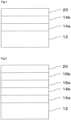
- the heat ray cutting film shown in Fig. 1 has, on one surface of a substrate 12, the light reflecting layer X1 (hereinafter, also referred to as a light reflecting layer 14a) and a light reflecting layer X2 (hereinafter, also referred to as a light reflecting layer 14b) obtained by fixing cholesteric liquid crystalline phases respectively, and an infrared ray absorbing layer 20.
- the light reflecting layer X1 hereinafter, also referred to as a light reflecting layer 14a
- a light reflecting layer X2 hereinafter, also referred to as a light reflecting layer 14b
- the above-mentioned light reflecting layer X2 may be provided on the above-mentioned light reflecting layer X1 side of the substrate via another light reflecting layer X3.
- Fig. 2 a cross-sectional view of a heat ray cutting film not falling within the terms of the claims is shown.
- the heat ray cutting film shown in Fig. 2 has, on one surface of the substrate 12, the light reflecting layer X1 (light reflecting layer 14a), the light reflecting layer X2 (light reflecting layer 14b), the light reflecting layer X3 (light reflecting layer 16a) and the light reflecting layer X3 (light reflecting layer 16b).
- the light reflecting layers X3, that is, the light reflecting layers 16b, having two layers each preferably has a reflection center wavelength substantially equal to that of the light reflecting layer 16a and has a helix direction of a cholesteric liquid crystalline phase opposite to each other.
- the heat ray cutting film of the present invention may be provided with a selective reflection property corresponding to respective wavelengths, for example, for 1400 to 2500 nm.
- the selective reflectivity wavelength region can be broadened and thus heat shielding performance is further enhanced, by further laminating a light reflecting layer obtained by fixing a cholesteric liquid crystalline phase, in particular, light reflecting layers obtained by fixing cholesteric liquid crystalline phases having optical rotations opposite to each other (that is, dextrorotary or levorotary).
- the visible light transmittance of the heat ray cutting film is preferably 70% or more, more preferably 72% or more, and particularly preferably 74% or more.
- the transmittance at 850 nm is preferably 10% or less, more preferably 5% or less, and particularly preferably 3% or less.
- the haze is preferably 1% or less, more preferably 0.8% or less, and particularly preferably 0.7% or less.
- the heat ray cutting film of the present invention has a light reflecting layer X1 and a light reflecting layer X2 obtained by fixing cholesteric liquid crystalline phases, wherein the light reflecting layer X1 and the light reflecting layer X2 reflect, respectively, circularly polarized lights in directions opposite to each other, reflection center wavelengths of the light reflecting layer X1 and the light reflecting layer X2 are within a range of 800 to 1100 nm and are substantially equal to each other, and the reflectivity of all light reflecting layers obtained by fixing cholesteric liquid crystalline phases is 80% or more.
- the reflectivity of the light reflecting layer obtained by fixing a cholesteric liquid crystalline phase is 80% or more, preferably 85% or more, and more preferably 90% or more.
- the heat ray cutting film of the present invention has the light reflecting layer X1 and the light reflecting layer X2 each obtained by fixing a cholesteric liquid crystalline phase, wherein the light reflecting layer X1 and the light reflecting layer X2 reflect, respectively, circularly polarized lights in directions opposite to each other, and reflection center wavelengths of the light reflecting layer X1 and the light reflecting layer X2 are within a range of 800 to 1100 nm and are substantially equal to each other.
- the light reflecting layer X1 and the light reflecting layer X2 reflect lights circularly polarized in directions opposite to each other, but in the heat ray cutting film of the present invention, preferably the light reflecting layer X1 contains a dextrorotary chiral agent and the light reflecting layer X2 contains a levorotatory chiral agent.
- the reflection center wavelength of the light reflecting layer X3 is preferably within a range of 800 to 1400 nm.
- the light reflecting layer X3 preferably has a reflection center wavelength within a range of 800 to 1100 nm and preferably can reflect a circularly polarized light in the same direction as that in the case of the light reflecting layer X1.
- each of light reflecting layers is about 1 ⁇ m to 8 ⁇ m (preferably about 3 to 7 ⁇ m).
- the thickness is not limited to these ranges.
- a light reflecting layer with an intended helical pitch can be formed by adjusting the kind of materials (mainly a liquid crystal material and a chiral agent) used for forming a layer, the concentration thereof, and the like.
- the thickness of a layer can be set to be within an intended range by adjusting a application amount.
- the use of a curable liquid crystal composition is preferable for forming each of light reflecting layers.
- the liquid crystal composition an embodiment of containing at least a rod-like liquid crystal compound, an optically active compound (chiral agent) and a polymerization initiator is preferable.
- Each component may be included in two or more kinds.
- the combined use of a polymerizable liquid crystal compound and a non-polymerizable liquid crystal compound is possible.
- the combined use of a low-molecular-weight liquid crystal compound and a high-molecular-weight liquid crystal compound is also possible.
- At least one selected from various additives such as a horizontal alignment agent, an unevenness inhibitor, a repelling inhibitor and a polymerizable monomer may be contained.
- a polymerization inhibitor, an oxidation inhibitor, an ultraviolet ray absorber, a light stabilizer, a coloring material, a metal oxide microparticles or the like can be added to the liquid crystal composition, in a range not lowering optical performance.
- a liquid crystal compound usable in the present invention may be so-called a rod-like liquid crystal compound or dicotic liquid crystal compound and is not particularly limited. Among these, a rod-like liquid crystal compound is preferable.
- rod-like liquid crystal compound usable in the present invention is a rod-like nematic liquid crystal compound.
- rod-like nematic liquid crystal compounds preferably used include azomethines, azoxys, cyanobiphenyls, cyanophenyl esters, benzoic esters, phenyl cyclohexanecarboxylates, cyanophenylcyclohexanes, cyano-substituted phenylpyrimidines, alkoxy-substituted phenylpyrimidines, phenyldioxanes, tolans and alkenylcyclohexylbenzonitriles. Not only a low-molecular-weight crystal compound but also a high-molecular-weight liquid crystal compound can also be used.
- a rod-like liquid crystal compound to be used in the present invention may be polymerizable or may be non-polymerizable.
- Rod-like liquid crystal compounds having no polymerizable group are described in various literatures (for example, Y. Goto et.al., Mol. Cryst. Liq. Cryst. 1995, Vol. 260, pp. 23 - 28 ).
- Polymerizable rod-like liquid crystal compounds can be obtained by introducing a polymerizable group in rod-like liquid crystal compounds.
- polymerizable groups include unsaturated polymerizable groups, an epoxy group and an aziridinyl group, among which unsaturated polymerizable groups are preferable and an ethylenically unsaturated polymerizable group is particularly preferable.
- a polymerizable group can be introduced into a molecule of a rod-like liquid crystal compound by various methods.
- the number of polymerizable groups which a polymerizable rod-like liquid crystal compound has is preferably 1 to 6, more preferably 1 to 3.
- Examples of polymerizable rod-like liquid crystal compounds include compounds described in Makromol. Chem., Vol.
- the above-described liquid crystal composition is one that exhibits a cholesteric liquid crystalline phase, and for that purpose, preferably the composition contains an optically active compound.
- the above-described rod-like liquid crystal compound is a molecule having an asymmetric carbon atom, even when no optically active compound is added, there may be a case where a cholesteric liquid crystalline phase can be stably formed.
- the above-described optically active compound can be selected from various known chiral agents (for example, described in Liquid Crystal Device Handbook, Chap. 3, Section 4-3, Chiral Agents for TN, STN, p 199, edited by Japan Society for the Promotion of Science, Board 142, 1989).
- Optically active compounds generally contain an asymmetric carbon atom, but axially asymmetric compounds or planarly asymmetric compounds containing no asymmetric carbon atom can also be used as a chiral agent.
- axially asymmetric compounds or planarly asymmetric compounds include binaphthyl, helicene, paracyclophane and derivatives thereof.
- Optically active compounds (chiral agents) may have a polymerizable group.
- an optically active compound has a polymerizable group and a rod-like liquid crystal compound simultaneously used also has a polymerizable group
- a polymer having a repeating unit derived from the rod-like liquid crystal compound and a repeating unit derived from the optically active compound can be formed by a polymerization reaction of the polymerizable optically active compound and the polymerizable rod-like liquid crystal compound.
- the polymerizable group which the polymerizable optically active compound has is preferably the same kind of group as the polymerizable group which the polymerizable rod-like liquid crystal compound has.
- the polymerizable group of the optically active compound is preferably an unsaturated polymerizable group, an epoxy group or an aziridinyl group, more preferably an unsaturated polymerizable group, and particularly preferably an ethylenically unsaturated polymerizable group.
- the optically active compound may be a liquid crystal compound.
- the optically active compound in the liquid crystal composition is preferably 1 to 30 mol% relative to the liquid crystal compound simultaneously used.
- the optically active compound in many cases does not influence on liquid crystallinity when used in lower amount, and thus lower use amount is preferable.
- a compound having strong twisting force is preferable so as to be capable of achieving a twisted alignment having a desired helical pitch even with a small amount.
- chiral agents exhibiting such strong twisting force for example, chiral agents described in Japanese Patent Laid-Open No. 2003-287623 are included and these can preferably be used in the present invention.
- the liquid crystal composition used for forming the light reflecting layer is preferably a polymerizable liquid crystal composition, and for that purpose, preferably contains a polymerization initiator.
- the polymerization initiator to be used is preferably a photopolymerization initiator capable of initiating a polymerization reaction by ultraviolet ray irradiation.
- photopolymerization initiators include ⁇ -carbonyl compounds (described in each of US Patent Nos. 2367661 and 2367670 ), acyloin ethers (described in US Patent No.
- the use amount of the photopolymerization initiator is preferably 0.1 to 20 mass% of a liquid crystal composition (in the case of an application liquid, solid components), more preferably 1 to 8 mass%.
- alignment controlling agent that contributes to stable or quick formation of a cholesteric liquid crystalline phase may be added to the above-described liquid crystal composition.
- alignment controlling agents include fluorine-containing (meth)acrylate-based polymers and compounds represented by general formulae (X1) to (X3) below. Two or more kinds selected from these may be contained. These compounds can reduce the tilt angle of molecules of a liquid crystal compound or can cause the molecules to align sunstantially horizontally at the air interface of the layer.
- horizontal alignment means that the long axis of a liquid crystal molecule and the film surface are parallel to each other, but strict parallelism is not required, and in the present description, the "horizontal alignment” is assumed to mean an alignment in which the tilt angle formed with the horizontal plane is less than 20 degrees.
- molecules of a liquid crystal compound are aligned at a large tilt angle, becase the helix axis of the cholesteric liquid crystalline phase is shifted from the normal line of the film surface, and thus the reflectivity may lower, or a finger print pattern is generated to thereby show the increase in haze or diffraction properties.
- fluorine-containing (meth) acrylate-based polymers usable as the alignment controlling agent are described in Japanese Patent Laid-Open No. 2007-272185 , paragraphs [0018] to [0043], and the like.
- R 1 , R 2 and R 3 each independently represents hydrogen atom or a substituent
- X 1 , X 2 and X 3 represent a single bond or a divalent linking group.
- Each of substituents represented by R 1 to R 3 is preferably a substituted or unsubstituted alkyl group (among these, more preferably an unsubstituted alkyl group or a fluorine-substituted alkyl group), an aryl group (among these, an aryl group having a fluorine-substituted alkyl group is preferable), a substituted or unsubstituted amino group, an alkoxy group, an alkylthio group or a halogen atom.
- Each of divalent linking groups represented by X 1 , X 2 and X 3 is preferably a divalent linking group selected from the group consisting of an alkylene group, an alkenylene group, a divalent aromatic group, a divalent hetero ring residue, -CO-, -NRa- (Ra is an alkyl group having 1 to 5 carbon atoms or hydrogen atom), -O-, -S-, -SO-, -SO 2 - and combinations thereof.
- the divalent linking group is more preferably a divalent linking group selected from the group consisting of an alkylene group, a phenylene group, CO-, -NRa-, -O-, -S- and - SO 2 - or a divalent linking group obtained by combining at least two groups selected from the group.
- the number of carbon atoms of the alkylene group is preferably 1 to 12.
- the number of carbon atoms of the alkenylene group is preferably 2 to 12.
- the number of carbon atoms of the divalent aromatic group is preferably 6 to 10.
- R represents a substituent and m represents an integer of 0 to 5.
- m represents an integer of 2 or more, the plural Rs may be the same or different.
- Substituents that are preferable as R are the same as those mentioned as the preferable range of substituents represented by R 1 , R 2 and R 3 .
- m represents preferably an integer of 1 to 3, and is particularly preferably 2 or 3.
- R 4 , R 5 , R 6 , R 7 , R 8 and R 9 each independently represents hydrogen atom or a substituent.
- Each of the substituents represented by R 4 , R 5 , R 6 , R 7 , R 8 and R 9 is preferably the same as those mentioned as preferable substituents represented by R 1 , R 2 and R 3 in the general formula (XI).
- Examples of compounds represented by the formulae (X1) to (X3) usable as the alignment controlling agent in the present invention include compounds described in Japanese Patent Laid-Open No. 2005-99248 .
- compounds represented by the general formulae (X1) to (X3) may be used in one kind or in two or more kinds in combination.
- the addition amount of the compound represented by any of the general formulae (X1) to (X3) in the liquid crystal composition is preferably 0.01 to 10 mass%, more preferably 0.01-5 mass%, particularly preferably 0.02 to 1 mass% of the mass of the liquid crystal compound.
- the heat ray cutting film of the present invention has a substrate.
- the substrate is not limited at all in terms of a material and optical properties, as long as the substrate has self-supporting properties and supports the above-described light reflecting layer. Depending on use applications, high transparency to ultraviolet light will be required.
- the substrate (substrate 12 in Figs. 1, 2 , and the like) is, for example, made of a polymer film and optical properties thereof are not particularly limited.
- the substrate is a plastic substrate (or a polymer film).
- members having in-plane retardation Re with variation may be used as a substrate.
- optical properties of the substrate 12 are not particularly limited, and the substrate may be an optically-anisotropic layer exhibiting phase difference or an optically-isotropic substrate.
- the substrate 12 is unnecessarily an optically-anisotropic layer such as an optically-anisotropic layer having strictly adjusted optical properties such as a phase difference of 1/2 wavelength.
- the substrate 12 may be made of a polymer film or the like in which the variation of in-plane retardation Re (1000) at the wavelength of 1000 nm is 20 nm or more.
- the substrate 12 may be made of a polymer film or the like in which the variation of Re (1000) is 100 nm or more.
- the in-plane retardation of the substrate is not also particularly limited, and for example, an optically-anisotropic layer or the like in which the in-plane retardation Re (1000) at the wavelength of 1000 nm is 800 to 13000 nm, can be used.
- polymer films having high transmission properties for visible light include various polymer films for optical films used as a member of display devices such as a liquid crystal display device.
- the substrates include films of polyester such as polyethylene terephthalate (PET), polybutylene terephthalate and polyethylene naphthalate (PEN); polycarbonate (PC) film, polymethyl methacrylate film; films of polyolefine such as polyethylene and polypropylene; polyimide film, triacetyl cellulose (TAC) film, and the like.
- PET polyethylene terephthalate
- PEN polybutylene terephthalate
- PEN polyethylene naphthalate
- PC polycarbonate
- films of polyolefine such as polyethylene and polypropylene
- polyimide film triacetyl cellulose (TAC) film, and the like.
- TAC triacetyl cellulose
- the substrate may be a special optically-anisotropic layer such as an optically-anisotropic layer having a phase difference of 1/2 wavelength, which is produced under a management of production process so as to satisfy prescribed optical properties, or a polymer film or the like which cannot be used as a prescribed optically-anisotropic layer.
- the substrate is an optically-anisotropic layer having a phase difference of 1/2 wavelength.
- both circularly-polarized lights of right circularly-polarized light and left circularly-polarized light can be reflected only with a light reflecting layer obtained by fixing a cholesteric liquid crystalline phase of one helical direction, and thus cost and production load can be suppressed.
- optically-anisotropic layer having a phase difference of 1/2 wavelength is not particularly limited and a preferable one can be used after appropriate change, as necessary.
- optically-anisotropic layer having a phase difference of 1/2 wavelength for example, one obtained by stretching a film made of transparent resin can be used.
- optically-anisotropic layers described in Japanese Patent Laid-Open No. 2002-40258 can also be used as the optically-anisotropic layer having a phase difference of 1/2 wavelength in the present invention, and the content described in Japanese Patent Laid-Open No. 2002-40258 , provides information regarding contents that may be used in embodiments of the present invention.
- the above-described transparent resin is not particularly limited, but one having a thickness of about 0.1 mm and having total light ray transmittance of 80% or more is preferable.
- the above-described transparent resins include acetate-based resins such as triacetyl cellulose, polyester-based resins, polyethersulfone-based resins, polycarbonate-based resins, chain-like polyolefine-based resin, polymer resins having an alicyclic structure, acrylic-based resins, polyvinyl alcohol-based resins, polyvinyl chloride-based resins, and the like. Among them, polycarbonate-based resins or polymer resins having an alicyclic structure are preferable.
- polymer resins having an alicyclic structure specifically include (1) norbornene-based polymers, (2) cyclic olefin-based polymers of monocycle type, (3) cyclic conjugated diene-based polymers, (4) vinyl alicyclic hydrocarbon polymers, hydrogenated products thereof, and the like.
- additives such as an oxidation inhibitor, a heat stabilizer, a light stabilizer, an ultraviolet ray absorber, an antistatic agent, a dispersant, a chlorine scavenger, a flame retardant, a nucleating agent, an antiblocking agent, an antifogging agent, a releasing agent, a pigment, an organic or inorganic filler, a neutralizing agent, a lubricant, a decomposing agent, a metal deactivator, a pollution controlling material, an antimicrobial agent and a thermoplastic elastomer, as necessary, can be added to the above-described resins.
- an oxidation inhibitor such as an oxidation inhibitor, a heat stabilizer, a light stabilizer, an ultraviolet ray absorber, an antistatic agent, a dispersant, a chlorine scavenger, a flame retardant, a nucleating agent, an antiblocking agent, an antifogging agent, a releasing agent, a pigment, an organic or inorgan
- optically-anisotropic layer having a phase difference of 1/2 wavelength a product obtained by applying, aligning and fixing a liquid crystal compound on a transparent resin, an inorganic crystal such as quartz or sapphire, or a structural birefringent plate obtained by providing fine unevenness on a resin or glass substrate can also be used.
- glass substitute resin-forming bodies or a combination of a glass substitute resin-forming body and a glass can be used.
- glass substitute resins include polycarbonate resins, acrylic-based resins, methacrylic-based resins, and the like.
- a material in which a glass substitute resin has a coating of a hard coat layer on it can also be used.
- hard coat layers include acrylic-based hard coat materials, silicone-based hard coat materials, melamine-based hard coat materials and materials obtained by dispersing inorganic particles such as silica, titania, alumina or zirconia in these hard coat materials.
- the above-described liquid crystal film obtained by fixing a cholesteric liquid crystalline phase is preferably a laminated body of three layers or more.
- the configuration results in forming a liquid crystal film obtained by fixing a cholesteric liquid crystalline phase/ optically-anisotropic layer having a phase difference of ⁇ /2 wavelength/ liquid crystal film obtained by fixing a cholesteric liquid crystalline phase, to thereby give, as a whole, a laminated body in which six layers or more of the cholesteric liquid crystal are laminated.
- the heat ray cutting film of the present invention has an infrared ray absorbing layer containing composite tungsten oxide microparticles. With such a configuration, light within the wavelength range of about 1100 to 2500 nm is absorbed and/or reflected, and the heat shielding properties can be further improved.
- the composite tungsten oxide is preferably represented by a general formula (1) below.
- a cesium-containing tungsten oxide in which the M element represents Cs is suitable because of high near infrared ray absorption ability.
- the amount of the M element to be added preferably satisfies the relation of 0.001 ⁇ x/y ⁇ 1.1 as a value of x/y based on the content of tungsten, and, in particular, x/y near 0.33 is preferable from the viewpoint of exhibiting suitable near infrared absorption ability.
- the composite tungsten oxide easily has a hexagonal crystal structure, and is also suitable in terms of the durability by having the crystal structure.
- the content of oxygen in the general formula (1) preferably satisfies the relation of 2.2 ⁇ zly ⁇ 3.0 as the z/y value based on the content of tungsten. More specifically, Cs 0.33 WO 3 , Rb 0.33 WO 3 , K 0.33 WO 3 , Ba 0.33 WO 3 and the like can be exemplified.
- the above-described inorganic near infrared ray absorbers may be used alone or can also be used in combination of two or more kinds.
- the average particle diameter of the above-described composite tungsten oxide microparticles is preferably 5 to 500 nm, more preferably 10 to 100 nm, and particularly preferably 20 to 50 nm.
- a method for producing the above-described composite tungsten oxide is not particularly limited but any of known methods can be used.
- intended oxide microparticles can be obtained by using a metal salt or a metal alkoxide as a raw material and hydrolyzing it in a reaction system containing water.
- inorganic microparticles may be made in an organic solvent or in an organic solvent in which a thermoplastic resin is dissloved.
- solvents used for these methods include acetone, 2-butanone, dichloromethane, chloroform, toluene, ethyl acetate, cyclohexanone, anisole, and the like. These may be used alone or by mixing plural kinds.
- the infrared ray absorbing layer preferably is a layer obtained by dispersing the composite tungsten oxide microparticles, in an ultraviolet curable resin or a thermoplastic resin.
- the infrared ray absorbing layer preferably contains at least one of an IR pigment, a color tone adjusting agent, a UV absorber, a light stabilizer and an oxidation inhibitor.
- the infrared ray absorbing layer preferably contains a UV absorber, a light stabilizer and an oxidation inhibitor from the viewpoint of light (UV) resistant properties.
- a method for producing the infrared ray absorbing layer containing the above-described composite tungsten oxide microparticles is not particularly limited, but a known method can be used.
- the infrared ray absorbing layer is preferably formed by application.
- the heat ray cutting film of the present invention may have another layer containing an organic material and/or an inorganic material.
- the heat ray cutting film of the present invention preferably further includes an ultraviolet ray reflecting layer obtained by fixing a cholesteric liquid crystalline phase.
- the ultraviolet ray reflecting layer obtained by fixing a cholesteric liquid crystalline phase is the same as the light reflecting layer X1 or the like except that the selective reflectivity wavelength is set within a wavelength region of ultraviolet rays by changing (increasing) the amount of a chiral agent.
- Respective light reflecting layers formed by fixing a cholesteric liquid crystalline phase tend to deteriorate by ultraviolet light irradiation, and in particular, deterioration due to ultraviolet rays of 380 nm or shorter in wavelength is remarkable.
- a layer containing a material that absorbs light within the range may be arranged, and furthermore, it is preferable to include an ultraviolet ray reflecting layer obtained by fixing a cholesteric liquid crystalline phase, because the deterioration can be suppressed remarkably.
- the heat ray cutting film of the present invention preferably further includes at least one of an easily adhering layer, a hard coat layer, an ultraviolet ray absorbing layer, a sticky layer and a surface protective layer.
- the above-described easily adhering layer is a layer for facilitating close adherence to another member (for example, an intermediate film sheet, and the like).
- the above-described easily adhering layer is preferably arranged as the outermost layer of one or both surfaces.
- the easily adhering layer can be arranged on the outermost light reflecting layer.
- the easily adhering layer can also be arranged on the rear surface of the substrate (the surface of the substrate on the side on which no light reflecting layer is arranged).
- Materials utilized for forming an easily adhering layer are selected from various materials depending on whether the easily adhering layer is to be formed adjacent to a light reflecting layer or to be formed adjacent to a substrate, or depending on material quality of another member to adhere.
- the light non-reflecting layers utilizable in the present invention include: an undercoating layer that enhances an adherence force between a light reflecting layer of a cholesteric liquid crystalline phase and a substrate; and an alignment layer prescribing more precisely the alignment direction of a liquid crystal compound used when forming a light reflecting layer.
- the undercoating layer and the alignment layer are preferably arranged between the at least one light reflecting layer and the substrate.
- the alignment layer may be arranged between light reflecting layers.
- the heat ray cutting film of the present invention may have the easily adhering layer as the outermost layer of one or both surfaces.
- the easily adhering layer has a function of improving the adhesiveness, for example, to an intermediate film for a laminated glass. More specifically, the easily adhering layer has a function of improving the adhesiveness between a light reflecting layer of a cholesteric liquid crystalline phase and/or a substrate, and an intermediate film for a laminated glass.
- Materials utilizable for forming an easily adhering layer include polyvinyl butyral (PVB) resin.
- the polyvinyl butyral resin is a kind of polyvinyl acetal generated by causing polyvinyl alcohol (PVA) and butyl aldehyde to react with each other by using an acid catalyst, and is a resin having a repeating unit shown below.
- the easily adhering layer is preferably formed by application.
- the easily adhering layer may be formed by application on the surface of a light reflecting layer of a cholesteric liquid crystalline phase and/or on the rear face of a substrate (surface on the side on which a light reflecting layer is not formed).
- the easily adhering layer can be formed by dissolving one of polyvinyl butyral resins in an organic solvent to thereby prepare an application liquid, by applying the application liquid onto the surface of a light reflecting layer of a cholesteric liquid crystalline phase and/or the rear face of a substrate, and by heating it to be dried.
- Examples of the solvent to be used for the preparation of the application liquid include methoxypropylacetate (PGMEA), methyl ethyl ketone (MEK), isopropanol (IPA) and the like.
- PGMEA methoxypropylacetate
- MEK methyl ethyl ketone
- IPA isopropanol
- Conventionally known various methods can be utilized as an application method.
- a temperature in drying a preferable range varies depending on materials used for preparing the application liquid and, generally, the range is preferably about 140 to 160°C.
- a drying time is also not particularly limited, but generally, the time is about 5 to 10 minutes.
- the easily adhering layer may be a layer including acrylic resin, styrene/acrylic resin, urethane resin, polyester resin or the like, which is referred to as so-called an undercoat layer.
- the easily adhering layer made of these materials can also be formed by application. Note that, among commercially available polymer films, some may have been given an undercoat, and thus such commercially available products can also be utilized as a substrate.
- the thickness of an easily adhering layer is preferably 0.1 to 2.0 ⁇ m.
- the heat ray cutting film of the present invention may have an undercoat ing layer between the light reflecting layer of a cholesteric liquid crystalline phase and the substrate.
- an undercoat ing layer between the light reflecting layer of a cholesteric liquid crystalline phase and the substrate.
- the undercoat examples include acrylic acid ester copolymers, polyvinyl chloride, styrene-butadiene rubber (SBR), aqueous polyesters, and the like. Furthermore, in an embodiment in which the surface of the undercoating layer adheres to an intermediate film, excellent adhesive properties between the undercoating layer and the intermediate layer are preferable, and from the viewpoint, the undercoating layer preferably contains polyvinyl butyral resin in addition to the above-described materials.
- the adhesive force is required to be appropriately adjusted, and thus an appropriate use of a hardener such as dialdehydes such as glutaraldehyde and 2,3-dihydroxy-1,4-dioxane or boric acid to harden the film is preferable.
- the addition amount of the hardener is preferably 0.2 to 3.0 mass% relative to the dry mass of the undercoating layer.
- the thickness of the undercoating layer is preferably 0.05 to 0.5 ⁇ m.
- the heat ray cutting film of the present invention may have an alignment layer between the light reflecting layer of a cholesteric liquid crystalline phase and the substrate.
- the alignment layer has a function of prescribing more precisely the alignment direction of liquid crystal compounds in the cholesteric liquid crystal layer.
- the alignment layer can be provided by techniques such as a rubbing treatment of an organic compound (preferably polymer), oblique evaporation of an inorganic compound, and formation of a layer having micro groves.
- alignment layers that generate an alignment function by impartment of an electric field, impartment of magnetic field or light irradiation are also known.
- the alignment layer is preferably formed on a surface of a polymer film by a rubbing treatment.
- the alignment layer is required to be adjacent to the light reflecting layer of a cholesteric liquid crystalline phase, the layer is preferably provided between the light reflecting layer of a cholesteric liquid crystalline phase, and the substrate or the undercoating layer.
- the undercoating layer may have the function of an alignment layer.
- the alignment layer may be provided between light reflecting layers.
- the alignment layer preferably has a certain degree of adhesive force for all of the adjacent light reflecting layers of a cholesteric liquid crystalline phase, and the undercoating layer or the substrate.
- the interface to be peeled may be an arbitrary interface, but when considering that a laminated intermediate film sheet is to be formed in a post-process, the peeling at the interface of the alignment layer and the undercoating layer is more preferable.
- Polymers of an organic compound are preferable as materials used as the alignment layer, and polymers cross-linkable by themselves or polymers to be crosslinked by a cross-linking agent are frequently used. Naturally, polymers having both functions are also used.
- Examples of polymers can include polymers such as polymethyl methacrylate, acrylic acid/ methacrylic acid copolymer, styrene/ maleinimide copolymer, polyvinyl alcohol and modified polyvinyl alcohol, poly(N-methylolacrylamide), styrene/ vinyltoluene copolymer, chlorosulfonated polyethylene, nitrocellulose, polyvinyl chloride, chlorinated polyolefine, polyester, polyimide, vinyl acetate/ vinyl chloride copolymer, ethylene/ vinyl acetate copolymer, carboxymethyl cellulose, gelatin, polyethylene, polypropylene and polycarbonate, and compounds such as a silane coupling agent.
- preferable polymers can include watersoluble polymers such as poly(N-methylolacrylamide), carboxymethyl cellulose, gelatin, polyvinyl alcohol and modified polyvinyl alcohol, furthermore preferably gelatin, polyvinyl alcohol and modified polyvinyl alcohol, particularly preferably polyvinyl alcohol and modified polyvinyl alcohol.
- the alignment layer preferably contains a polyvinyl butyral resin in addition to the above-mentioned materials.
- the thickness of the above-mentioned alignment layer is preferably 0.1 to 2.0 ⁇ m.
- the heat shielding effect of the heat ray cutting film of the present invention can also be improved not only by reflection properties but also by light absorption properties of a material.
- the heat ray cutting film of the present invention may contain an additive in arbitrary layer.
- light in the near infrared region can be absorbed and thus the heat shielding properties can be further improved, by adding a coloring material that exhibits absorption properties in a near infrared region, preferably within a wavelength region of about 780 to 940 nm to the substrate or at least one light reflecting layer, or by arranging separately a layer containing the coloring material.
- the deterioration can be preferably suppressed remarkably, for example, by adding a material (ultraviolet ray absorber) absorbing the light in the wavelength region to the substrate or at least one light reflecting layer, or by arranging separately a layer containing the material.
- a material ultraviolet ray absorber
- the coloring material, metal oxide microparticles, the ultraviolet ray absorber or the like may have an influence on the alignment of a liquid crystal
- these materials are preferably added to the substrate or a layer other than the light reflecting layer, or are preferably added to another member when the light reflecting layer is integrated with the another member.
- These materials may have been added in the same layer, or added respectively in layers different from each other.
- Members (layer, substrate and the like) to which respective materials are to be added will be determined so that effects based on functions of respective materials can be more effectively obtained.
- members to which these materials are to be added will be determined so that a planar failure and the like are not generated and transparency is not lowered remarkably, while considering various properties (influence on haze, solubility, melting properties, application properties) of these materials.
- an ultraviolet ray absorber is preferably added to a member which light enters prior to the light reflecting layer.
- the deterioration of the light reflecting layer due to ultraviolet rays can be suppressed by adding the ultraviolet ray absorber to the member.
- a coloring material or metal oxide microparticles are preferably added to a member which light enters later than the light reflecting layer.
- additives such as an ultraviolet ray absorber, a coloring material and metal oxide microparticles may be contained in an arbitrary layer of the heat ray cutting film of the present invention, in the embodiment of the present invention.
- the above-described additive is preferably contained in the above-described substrate or the above-described light non-reflective layer, and for example, the additive is preferably contained in any of the easily adhering layer, the alignment layer, the undercoating layer and the substrate.
- the layer to which additive is to be added is selected depending on the positional relationship between the light reflecting layer of a cholesteric liquid crystalline phase and the sun light.
- the ultraviolet ray absorber is preferably contained in a layer on the side closer to the sun light than the light reflecting layer of a cholesteric liquid crystalline phase, and the coloring material and metal oxide microparticles are preferably contained in a layer on the side farther to the sun light than the light reflecting layer of a cholesteric liquid crystalline phase.
- layers preferable for containing each of the ultraviolet ray absorber, the coloring material and metal oxide microparticles are changed, and thus, as to respective raw materials, it is necessary to appropriately adjust a composition, a solvent, a use amount and the like, and to adopt a method for containing thereof, which is considered to be the best.
- an ultraviolet ray absorber is contained in at least one of the light reflecting layer, the easily adhering layer, the undercoating layer, the alignment layer and the substrate.
- Some kinds of ultraviolet ray absorbers influence the alignment of a liquid crystal, and thus the addition of the ultraviolet ray absorber in a member other than the light reflecting layer (layer, substrate and the like) is preferable.
- the embodiment of the present invention can adopt various forms, and the addition to a member which light enters prior to the light reflecting layer is preferable.
- the addition to a layer arranged between a glass plate arranged on the open air side and the light reflecting layer of a cholesteric liquid crystalline phase is preferable.
- the incorporation in an intermediate film caused to adhere to a glass plate arranged on the open air side, or in the glass itself arranged on the open air side is also preferable.
- Examples of compounds usable as the ultraviolet ray absorber include benzotriazole-based, benzodithiol-based, coumarin-based, benzophenone-based, salicylic ester-based and cyanoacrylate-based ultraviolet ray absorbers; titanium oxide and zinc oxide, and the like.
- Examples of particularly preferable ultraviolet ray absorbers include Tinuvin 326, 328, 479 (all are manufactured by Ciba Japan).
- the kind and blending amount of the ultraviolet ray absorber are not particularly limited and can be appropriately selected in accordance with the purpose.
- a member containing the ultraviolet ray absorber preferably has a function of making the transmittance of ultraviolet rays having wavelengths of 380 nm or less be 0.1% or less, because the deterioration of the light reflecting layer can be remarkably reduced and yellowing caused by ultraviolet rays can be dramatically reduced. Accordingly, determination of the kind and blending amount of the ultraviolet ray absorber so as to satisfy the above properties is preferable.
- the heat ray cutting film of the present invention preferably contains a coloring material in at least one of the light reflecting layer, the easily adhering layer, the undercoating layer, the alignment layer and the substrate. Since some kinds of coloring materials influence the alignment of a liquid crystal, the addition to a member (layer, substrate and the like) other than the light reflecting layer is preferable. Note that, in some cases, diffusion or absorption generated when light passes through a member containing the coloring material lowers the efficiency of infrared light reflection by the light reflecting layer of a cholesteric liquid crystalline phase to thereby lower heat shielding performance. Accordingly, although the embodiment of the present invention can adopt various shapes, the addition to a member which light enters later than the light reflecting layer is preferable.
- the coloring material is contained in a layer arranged between a glass plate arranged on the indoor side and the light reflecting layer of a cholesteric liquid crystalline phase.
- the coloring material is contained in an intermediate film which is to be caused to adhere to a glass plate arranged on the indoor side, or a glass plate itself arranged on the indoor side.
- Both dye and pigment can be used as the coloring material.
- the use of a material exhibiting absorption properties for a wavelength region of 780 to 940 nm is preferable because it can further improve heat shielding properties.
- the use of the material is also preferable from the viewpoint of being capable of reducing coloring. Cyan dyes and cyan pigments are preferable as an absorption material for a wavelength region of 780 to 940 nm.
- dyes used as a cyan dye include azomethine dyes such as an Indoaniline dye and an indophenol dye; polymethine dyes such as a cyanine dye, an oxonol dye and a merocyanine dye; carbonium dyes such as a diphenylmethane dye, a triphenylmethane dye and a xanthene dye; phthalocyanine dyes; anthraquinone dyes; aryl or heterylazo dyes having, for example, phenols, naphthols or anilines as a coupling component, and indigo/ thioindgo dyes.
- azomethine dyes such as an Indoaniline dye and an indophenol dye
- polymethine dyes such as a cyanine dye, an oxonol dye and a merocyanine dye
- carbonium dyes such as a diphenylmethane dye, a triphenylmethan
- These dyes may be ones that exhibit cyan for the first time when a part of chromophores is dissociated, and a counter cation on this case may be an inorganic cation such as an alkali metal or ammonium, or an organic cation such as pyridinium or quaternary ammonium salt, or, furthermore, a polymer cation having these in a partial structure.
- black dyes such as a polyazo dye can also be used.
- pigments used as a cyan pigment phthalocyanine pigments, anthraquinone-based indanthrone pigments (such as C. I. Pigment Blue 60) and dye-lake pigment-based triarylcarbonime pigments are preferable, in particular, phthalocyanine pigments (preferable examples include copper phthalocyanines such as C. I. Pigment Blue 15:1, 15:2, 15:3, 15:4 and 15:6, pigments described European Patent 860475 regarding monochloro or low chlorinated copper phthalocyanine and aluminum phthalocyanine, metal-free phthalocyanine being C.
- I. Pigment Blue 16 phthalocyanine having Zn, Ni or Ti as a center metal, among these preferable are C. I. Pigment Blue 15:3 and 15:4, aluminum phthalocyanine
- phthalocyanine pigments preferable examples include copper phthalocyanines such as C. I. Pigment Blue 15:1, 15:2, 15:3, 15:4 and 15:6, pigments described European
- a coloring material being a light absorbing raw material may generate deviation in a transmittance spectrum of a visible light ray wavelength region and produce color in transmitted light.
- a coloring material can be selected so as to give an intended color, by positive utilization of the characteristics.
- the coloring may not be desirable.
- coloring material yellow dye, yellow pigment, magenta dye, magenta pigment, etc.
- Known coloring materials described in various literatures can be utilized as these coloring materials. (Dyes are described in Japanese Patent Laid-Open No. 2005-105175 or the like, and pigments are described in Japanese Patent Laid-Open No. 2009-67956 or the like.)
- each of light reflecting layers in the heat ray cutting film of the present invention can be formed by various methods.
- An example is a method of forming it by an application to be described later, and more specifically, each of light reflecting layers can be formed by applying a curable liquid crystal composition capable of forming a cholesteric liquid crystalline phase onto a surface of a substrate, an alignment layer, a light reflecting layer or the like, by making the composition into a cholesteric liquid crystalline phase, and after that, by progressing a curing reaction (such as a polymerization reaction or cross-linking reaction) to thereby cure the same.
- a curing reaction such as a polymerization reaction or cross-linking reaction
- the heat ray cutting film of the present invention is preferably obtained by an application method.
- the method is characterized by including the steps of: forming, by an application, the light reflecting layer X1 obtained by fixing a cholesteric liquid crystalline phase on the surface of the substrate; forming, by an application, the light reflecting layer X2 obtained by fixing a cholesteric liquid crystalline phase on the surface on the light reflecting layer X1 side of the substrate having the light reflecting layer X1; and forming an infrared ray absorbing layer by applying an application liquid containing a composite tungsten oxide microparticles onto the surface on the light reflecting layer X2 side of the substrate having the light reflecting layer X1 and the light reflecting layer X2.
- the process of forming the above-described light reflecting layer X1 by an application and the process of forming the above-described light reflecting layer X2 by an application include preferably applying a curable liquid crystal composition containing a curable cholesteric liquid crystal compound onto the surface of the substrate, drying the above-described curable liquid crystal composition applied to thereby align the above-described curable cholesteric liquid crystal compound and align it into a state of a cholesteric liquid crystalline phase, and progressing the curing reaction of the above-described curable liquid crystal composition and fixing a cholesteric liquid crystalline phase.
- An example of the production method is a production method including at least:
- a heat ray cutting film having the same configuration as the configuration shown in Fig. 1 can be made by repeating two times the (1) and (2) steps on the one surface of the substrate.
- the direction of twisting a cholesteric liquid crystalline phase can be adjusted depending on the kind of a liquid crystal to be used or the kind of a chiral agent to be added, and the helical pitch (that is, the central reflection wavelength) can be arbitrarily adjusted by concentrations of these materials.
- a wavelength in a specific region in which a light reflecting layer reflects light can be shifted by various factors in a production method, and the wavelength can be shifted by conditions such as temperature, luminous intensity, and irradiation time, when fixing a cholesteric liquid crystalline phase, in addition to addition amounts of a chiral agent or the like.
- the above-described curable liquid crystal composition is applied.
- the above-described curable liquid crystal composition is preferably prepared as an application liquid in which materials are dissolved or dispersed in a solvent.
- the application of the above-described application liquid can be performed by various methods such as a wire bar coating method, an extrusion coating method, a direct gravure coating method, a reverse gravure coating method and a die coating method.
- the liquid crystal composition can also be discharged from a nozzle by using an inkjet apparatus to thereby form a coating film.
- the curable liquid crystal composition applied on the surface and serving as a coating film is put into a state of a cholesteric liquid crystalline phase.
- the above-described curable liquid crystal composition is prepared as an application liquid containing a solvent
- the state of a cholesteric liquid crystalline phase can be achieved by drying a coating film and removing the solvent.
- the above-described coating film may be heated.
- the state of the cholesteric liquid crystalline phase can be stably achieved by once heating of the film to a temperature of an isotropic phase, and, after that, cooling or the like of it to the transition temperature to the cholesteric liquid crystalline phase.
- the transition temperature of the above-described curable liquid crystal composition to a liquid crystalline phase is preferably within a range of 10 to 250°C, more preferably within a range of 10 to 150°C from the viewpoint of production suitability or the like. When the transition temperature is less than 10°C, in order to lower the temperature to a temperature range that leads to the liquid crystalline phase, a cooling step or the like may become necessary.
- transition temperature exceeds 200°C
- a high temperature is required in order to lead once to an isotropic liquid state requiring a temperature higher than the temperature range leading to the liquid crystalline phase, which is disadvantageous from the viewpoint of a waste of heat energy, deformation or degeneration of a substrate, and the like.
- ultraviolet rays are irradiated to the coating film that has been put into a state of a cholesteric liquid crystalline phase to thereby progress a curing reaction.
- a light source such as an ultraviolet lamp is used.
- the curing reaction of the liquid crystal composition progresses, and the cholesteric liquid crystalline phase is fixed and the light reflecting layer is formed.
- Irradiation energy of ultraviolet rays is not particularly limited, but generally, about 100 mJ/cm 2 to 800 mJ/cm 2 is preferable. Furthermore, a time period of irradiating the coating film with ultraviolet rays is not particularly limited, but the time will be determined from both viewpoints of sufficient strength of a hardened film and productivity.
- ultraviolet ray irradiation may be performed under heated conditions.
- the temperature in ultraviolet ray irradiation is preferably maintained within a temperature range in which a cholesteric liquid crystalline phase is exhibited so that the cholesteric liquid crystalline phase is not disturbed.
- the oxygen concentration in an atmosphere takes part in a polymerization degree, and in the case where an intended polymerization degree is not achieved in the air and the film strength is insufficient, preferably the oxygen concentration in the atmosphere is lowered by a method of nitrogen substitution or the like.
- a preferable oxygen concentration 10% or less is preferable, 7% or less is more preferable and 3% or less is most preferable.
- the reaction ratio of a curing reaction (for example, polymerization reaction) advanced by ultraviolet ray irradiation is preferably 70% or more, more preferably 80% or more and further more preferably 90% or more, from the viewpoint of preservation of mechanical strength of the layer or the like and suppression of outflow of unreacted materials from the layer.
- a method of increasing the irradiation amount of ultraviolet rays with which irradiation is performed, and polymerization under a nitrogen atmosphere or heated conditions are effective.
- a method of holding the product in a state of a temperature higher than a polymerization temperature to thereby further progress the reaction by a thermal polymerization reaction, or a method of performing ultraviolet ray irradiation once again (however, the irradiation is performed by conditions satisfying the conditions of the present invention), after once performing the polymerization, can also be used.
- the measurement of the reaction rate can be performed by comparing the absorption intensity of an infrared vibration spectrum of a reactive group (for example, polymerizable group) before and after the reaction progress.
- the cholesteric liquid crystalline phase is fixed and the light reflecting layer is formed.
- a state in which a liquid crystalline phase has been "fixed” a state in which the alignment of a liquid crystal compound having become a cholesteric liquid crystalline phase is maintained, is the most typical and preferable embodiment.
- the state is not limited only to it, but specifically, a state in which the layer does not show a flow property within a temperature range of usually 0°C to 50°C or -30°C to 70°C under severer conditions and can continue to keep stably a fixed alignment shape without generating a change in the alignment shape by an external field or an external force, is assumed to be meant.
- the alignment state of a cholesteric liquid crystalline phase is fixed by a curing reaction progressed by ultraviolet ray irradiation.
- a liquid crystal composition in the light reflecting layer finally shows liquid crystalline properties.
- a liquid crystal composition may have been made into high molecular weight by a curing reaction and have already lost liquid crystalline properties.
- a laminated intermediate film sheet for glass containing the heat ray cutting film of the present invention is characterized by containing the heat ray cutting film of the present invention and an intermediate film sheet arranged on the at least one outermost layer of the heat ray cutting film.
- the intermediate film sheet can be stuck to one surface and/or both surfaces of the heat ray cutting film of the present invention.
- the laminated intermediate film sheet for glass preferably has intermediate film sheets on both outermost layers, respectively, of the infrared light reflecting layer or the heat ray cutting film.
- the intermediate film sheet can be easily incorporated into the laminated glass as the laminated intermediate film sheet for laminated glass, by sticking the intermediate film sheet.
- the intermediate film sheet may be stuck with the substrate remained or may be stuck after the substrate is peeled off, but when considering that the film sheet will be incorporated into the laminated glass in a post-process, the film sheet is preferably stuck with the intermediate film sheet after the substrate is peeled off in consideration of the thickness, flexibility and compression resistance.
- General intermediate film sheets used for making a laminated glass can be utilized as the intermediate film sheet.
- Specific examples thereof include a sheet or the like made from a composition containing a polyvinyl butyral resin or an ethylenevinyl acetate copolymer as a main raw material.
- the thickness of the intermediate film sheet is generally about 380 to 760 ⁇ m.
- the heat ray cutting film of the present invention can be formed into a laminated intermediate film sheet for laminated glass sandwiched by intermediate film sheets, by being stuck with intermediate film sheets on both surfaces.
- the method for producing the laminated intermediate film sheet for glass is a production method including at least:
- the lamination processing is preferably performed under conditions of certain degree of heating and pressurization.
- the temperature on the film surface side to which the intermediate film sheet adheres is preferably 50 to 130°C, more preferably 70 to 100°C.
- pressurization is preferable.
- the pressurization condition is preferably less than 2.0 kg/cm 2 , more preferably within a range of 0.5 to 1.8 kg/cm 2 , and further more preferably within a range of 0.5 to 1.5 kg/cm 2 .
- the substrate (or a laminated body including at least the substrate) may be peeled off from the heat ray cutting film. That is, a laminated intermediate film sheet obtained after the lamination may not have the substrate.
- an example of methods for producing the laminated intermediate film sheet for laminated glass is a method for producing a laminated intermediate film sheet for glass using a heat ray cutting film in which a substrate is arranged only on one surface as the heat ray cutting film, including, in the first step, a step of sticking the first intermediate film sheet to the surface on the side opposite to the surface on which the substrate of the heat ray cutting film is arranged, and simultaneously with or after the step, peeling the substrate included in the heat ray cutting film to form the first laminated body, and, in the second step, sticking the second intermediate film sheet to the surface of the first laminated body obtained by peeling of the substrate.
- a laminated intermediate film sheet for glass not including a substrate can be produced, and by using the laminated intermediate film sheet for glass, an infrared reflective laminated glass not including a substrate can easily be made.
- a temperature when a substrate is peeled off from the light reflecting layer of a cholesteric liquid crystalline phase is preferably 40°C or more, more preferably 40 to 60°C.
- the laminated glass of the present invention is characterized by including two glasses, and the laminated intermediate film sheet for glass of the present invention included between the two glasses.
- the laminated intermediate film sheet for laminated glass can be made into a laminated glass by being sandwiched between two glass plates.
- General glass plates can be utilized as the glass plate.
- a heat ray absorbing glass having an absorption in the visible light region can be utilized. It is possible to adjust visibility (transmittance) as glass and heat shielding performance by adjustment of the absorption in the visible light region.
- a heat ray absorbing glass as described in Japanese Patent Nos.
- absorption in the visible light region and color as transmitted light can be adjusted by incorporating an oxide of a metal such as iron, tin, nickel, cobalt or selenium.
- a metal such as iron, tin, nickel, cobalt or selenium.
- the heat ray absorbing glass is used as a front glass for automobiles, it is preferable, as a laminated glass, to enhance heat shielding performance while suppressing absorption in the visible light region so as to satisfy "visible light transmittance (standard light source A) of 70% or more" prescribed in JIS-R-3211 and adjusting color of transmitted light.
- a heat ray absorbing glass one having visible light transmittance (standard light source A) of within a range of 80 to 95% and a main wavelength measured using the standard light source A within a range of 495 to 560 nm is preferable.
- the thickness of a glass plate is not particularly limited, and a preferable range thereof varies depending on the use applications.
- a glass plate having a thickness of 2.0 to 2.3 mm is preferable.
- the use of a glass plate having a thickness of about 40 to 300 ⁇ m is preferable.
- the thickness is not limited within the above range.
- a laminated body sandwiched between glass plates may have a configuration of glass plate/ intermediate film/ substrate/ light reflecting layer obtained by fixing a cholesteric liquid crystal/ optically-anisotropic layer having a phase difference of 1/2 wavelength/ light reflecting layer obtained by fixing a cholesteric liquid crystal substrate/ intermediate film/ glass plate, laminated in this order.
- a substrate a PET film etc. used in film formation other than an optically-anisotropic layer having a phase difference of 1/2 wavelength
- it may have a configuration of glass plate/ intermediate film/ light reflecting layer obtained by fixing a cholesteric liquid crystal/ optically-anisotropic layer having a phase difference of 1/2 wavelength/ light reflecting layer obtained by fixing a cholesteric liquid crystal/ intermediate film/ glass plate, laminated in this order.
- helical directions of liquid crystalline phases obtained by fixing cholesteric liquid crystals lying on both surfaces of the optically-anisotropic layer having a phase difference of 1/2 wavelength are desirably the same direction each other for those having the same reflection center wavelength.
- the laminated intermediate film sheet for laminated glass can be made into a laminated glass by being sandwiched between two glass plates.
- a production method of the laminated glass preferably includes a step of sandwiching the laminated intermediate film sheet for laminated glass between two glass plates to thereby produce a laminated body sandwiched between glass plates, and pressure-bonding the laminated body sandwiched between the glass plates with heating.
- a method is adopted in which a heat treatment and pressurizing treatment (such as squeezing it with a rubber roller) are repeated several times, and at the end, a heat treatment is performed under a pressurized condition utilizing an autoclave and the like.
- a heat treatment and pressurizing treatment such as squeezing it with a rubber roller
- a laminated body in which the aforementioned two intermediate films are sandwiched between the glass plates not in contact with each other is preferably pressure-bonded with heating.
- the laminated body and the glass plate are temporarily pressure-bonded at a temperature of 80 to 120°C for 30 to 60 minutes under a reduced pressure with a vacuum bag or the like, and, after that, are stuck to each other in a autoclave at a temperature of 120 to 150°C under an applied pressure of 1.0 to 1.5 MPa to thereby form a laminated glass, in which the laminated body is sandwiched between two glasses.
- the laminated body and the glass plate may be stuck using a sticky material and the like.
- the time of heated pressure bonding at a temperature of 120 to 150°C under an applied pressure of 1.0 to 1.5 MPa is preferably 20 to 90 minutes.
- a cooling procedure is not particularly limited.
- the cooling may be carried out while appropriately releasing the pressure to thereby give a laminated glass body.
- the lowering of the temperature in a state of maintaining the pressure means lowering temperature such that an internal pressure of an apparatus in the heated pressure bonding (preferably 130°C) becomes 75% to 100% of that in the heated pressure bonding at 40°C.
- Methods for lowering the temperature in a state of maintaining the pressure are not particularly limited as long as the pressure is within the above-described range when the temperature is lowered to 40°C, but an embodiment in which the temperature is lowered without leaking the pressure from the inside of the apparatus so that the pressure in the pressure apparatus loweres spontaneously as the temperature lowers, or an embodiment in which the temperature is lowered with pressure furthermore applied from the outside so that the internal pressure of the apparatus does not lower as the temperature lowers, is preferable.
- cooling to 40°C is preferably carried out in 1 to 5 hours, after performing the heated pressure bonding at 120 to 150°C.
- a process of releasing the pressure is preferably performed. Specifically, after lowering the temperature in a state of maintaining the pressure, preferably the pressure is released after the temperature in the autoclave becomes 40°C or less and the temperature is lowered.
- the method for producing a laminated glass body preferably includes steps of laminating the first glass, the first intermediate film, the infrared ray reflecting layer, the second intermediate film and the second glass in this order, after that, performing heated pressure bonding at a temperature of 120 to 150°C while applying a pressure of 1.0 to 1.5 MPa, lowering the temperature in a state of maintaining the pressure, and releasing the pressure.
- thermocompression bonding may be the whole area of the the glass plate or may be only the peripheral part of the glass plate, and the thermocompression bonding in the peripheral part can further suppress the generation of wrinkles.
- the heat ray cutting film of the present invention preferably may exhibit selective reflectivity properties having reflection peaks at 850 to 900 nm, 1010 to 1070 nm and 1190 to 1290 nm which correspond to the peaks of the solar light energy. Reflection plates of such properties are stuck to windows of constructions such as houses and buildings, or of vehicles such as automobiles as a member for shielding solar heat.
- the heat ray cutting film of the present invention can be subjected to the use applications as a member itself for shielding solar heat (such as a heat-shielding glass and a heat-shielding film).
- a heat ray cutting film that exhibits preferable transmittance for visible light and haze can be provided by selecting materials and adjusting production conditions or the like, and depending on the use applications. For example, in an embodiment used for a use application with high transmittance for visible light, a heat ray cutting film in which transmittance for visible light is 90% or more and reflectivity of infrared satisfies the above-described reaction, can be made.
- the heat ray cutting film of the present invention, the laminated intermediate film sheet for glass and the laminated glass of the present invention are preferably used as window members for constructions or vehicles.
- Table 1 Table of composition of application liquid (R1) Material (kind) Material name (manufacturer) Amount rod-like liquid crystalline compound RM-257 (Merck) 10.000 parts by mass chiral agent LC-756 (BASF) adjusted according to targeted reflection wavelength polymerization initiator Irgacure 819 (Ciba Specialty Chemicals) 0.419 parts by mass alignment controlling agent Compound 1 shown below 0.016 parts by mass solvent 2-butanone (Wako Pure Chemical Industries, Ltd.) 15.652 parts by mass Table 2 Composition table of application liquid (L1) Material (kind) Material name (manufacturer) amount rod-like liquid crystalline compound RM-257 (Merck) 10.000 parts by mass chiral agent Compound 2 shown below adjusted according to targeted reflection wavelength polymerization initiator Irgacure 819 (Ciba Specialty Chemicals) 0.419 parts by mass alignment controlling agent compound 1 shown below 0.016
- Alignment control agent Compound 1 (compound described in Japanese Patent Laid-Open No. 2005-99248)
- Chiral agent Compound 2 (compound described in Japanese Patent Laid-Open No. 2002-179668)
- application liquids (R2) to (R7) were prepared in the same manner as that in the application liquid (R1), except for modifying the amount of the chiral agent LC-756. All of (R1) to (R7) were application liquids for right circularly-polarized light reflection, and the central reflection wavelengths thereof were as described in Table 3 below.
- Table 3 Application liquid (R1) to (R7) and central reflection wavelengths thereof
- application liquids (L2) to (L7) were prepared in the same manner as that in the application liquid (L1), except for modifying the amount of the chiral agent (Compound 2). All of (L1) to (L7) were application liquids for left circularly-polarized light reflection and central reflection wavelengths were as described in Table 4 below.
- Table 4 Application liquid (L1) to (L7) and central Reflection wavelengths thereof
- An application liquid (C) obtained by dispersing composite tungsten oxide microparticles was prepared.
- the composition of the application liquid (C) was as described in Table 5 below.
- an average particle diameter of cesium-containing tungsten oxide microparticles contained in a cesium-containing tungsten oxide dispersed liquid was measured using Zetasizer NanoZS (manufactured by Malvern) and was 30 nm.
- Table 5 Composition table of application liquid (C) Material (kind) Material name (manufacturer) Amount composite tungsten oxide cesium-containing tungsten oxide dispersed liquid (Sumitomo Metal Mining Co., Ltd.) 50.000 parts by mass UV curable monomer A-TMMT (Shin-Nakamura Chemical Co., Ltd.) 5.000 parts by mass polymerization initiator Irgacure 819 (Ciba Specialty Chemicals) 0.400 parts by mass solvent methyl isobutyl ketone (Wako Pure Chemical Industries, Ltd.) 44.600 parts by mass
- An application liquid (C') obtained by dispersing composite tungsten oxide microparticles was prepared by addition of a light stabilizer Hostavin N30 among an IR pigment, a color tone adjusting agent, a UV absorber, a light stabilizer and an oxidation inhibitor, in 3 parts by mass, to the application liquid (C) prepared as described above.
- An application liquid (C") obtained by dispersing composite tungsten oxide microparticles was prepared in the samemanner as the preparation of the application liquid (C),except for replacing the cesium-containing tungsten oxide dispersed liquid with a tungsten oxide dispersed liquid (manufactured by Sukgyung AT Co., Ltd.) having cesium-containing tungsten oxide of 100 nm in an average particle diameter,.
- an application liquid (C′′′) obtained by dispersing composite tungsten oxide microparticles was prepared in the same manner as the preparation of the application liquid (C), except for replacing the cesium-containing tungsten oxide dispersed liquid with a tungsten oxide dispersed liquid (manufactured by Sukgyung AT Co., Ltd.) having cesium-containing tungsten oxide of 400 nm in an average particle diameter.
- ITO paint (trade name: PI-3, manufactured by Mitsubishi Materials Electronic Chemicals Co., Ltd.) was used as an application liquid (D) obtained by dispersing indium tin oxide (ITO) microparticles.
- a heat ray cutting film was prepared using prepared application liquids (R2) and (L2), according to a procedure described below.
- a PET film manufactured by FUJIFILM Corporation (no undercoating layer, thickness: 75 ⁇ m) was used as a substrate.
- the application liquid (C) was applied at room temperature onto the second cholesteric liquid crystal film (light reflecting layer X2) formed as described above using a wire bar such that a thickness after drying became 2 ⁇ m. After the solvent was removed by performing drying at room temperature for 90 seconds, heating was performed in an atmosphere of 90°C for 90 seconds. Subsequently, UV irradiation was performed with an electrodeless lamp "D bulb" (90 mW/cm 2 ) manufactured by Fusion UV Systems with an output of 60% for 3 to 6 seconds, and an infrared ray absorbing film in which composite tungsten oxide microparticles was dispersed in an ultraviolet curing resin was laminated.
- an electrodeless lamp "D bulb” 90 mW/cm 2
- Example 1 a heat ray cutting film of Example 1, in which two light reflecting layers on a substrate and the infrared ray absorbing layer further on the second light reflecting layer were laminated, was prepared.
- Heat ray cutting films of Examples 2 to 7 were made in the same procedure as that in Example 1, except for modifying the application liquid to be applied and the number of lamination layers in the formation of a light reflecting layer, as described in Table 6 below.
- a heat ray cutting film of Comparative Example 1 was prepared in the same procedure as that in Example 1, except for modifying the application liquid to be applied in the formation of a light reflecting layer, as described in Table 7 below, and for omitting the lamination of an infrared absorbing layer.
- a dry thickness of a light reflecting layer was larger than 6 ⁇ m
- a light reflecting layer larger than 6 ⁇ m was formed under conditions of room-temperature drying for 60 seconds and an atmosphere at 125°C for 3 minutes (UV curing time was the same).
- a heat ray cutting film of Comparative Example 2 was produced in the same manner as that in Example 1, except for modifying the application liquid to be applied in the formation of a light reflecting layer, as described in Table 7 below, and for using an application liquid (D) in the formation of an infrared ray absorbing layer.
- Heat ray cutting films of Comparative Examples 3 and 4 were made in the same procedure as that in Example 1, except for modifying the application liquid to be applied and the lamination number in the formation of a light reflecting layer, as described in Table 7 below.
- a heat ray cutting film of Comparative Example 5 was prepared in the same procedure as that in Example 1, except for modifying the film thickness in the formation of a light reflecting layer to thereby modify reflectivity of the second light reflecting layer in 800 to 1100 nm as described in Table 7 below.
- a heat ray cutting film of Comparative Example 6 was prepared in the same procedure as that in Example 1, except for using only the application liquid (R2) in the formation of the light reflecting layer to thereby modify the lamination number of the light reflecting layer to 1.
- a heat ray cutting film of Comparative Example 7 was prepared in the same procedure as that in Example 1, except for laminating an infrared ray absorbing layer having a thickness of 3.5 ⁇ m on the substrate without forming a light reflecting layer.
- a reflection spectrum and a transmission spectrum were measured through the use of a spectrophotometer "V-670” manufactured by Jasco Corporation, and calculation was performed on the basis of the visible light calculation method described in JIS A5759.
- the visible light transmittance is required to be 70% or more.
- a reflection spectrum and a transmission spectrum were measured through the use of a spectrophotometer "V-670" manufactured by Jasco Corporation, and calculation was performed on the basis of the calculation method of the shielding factor described in JIS A5759.
- the shielding factor is required to be 0.65 or less.
- Haze was measured in conformity with JIS K 7136:2000 (Plastics-Determination of haze for transparent materials).
- the haze is required to be 1.0% or less.
- Table 6 Configuration of heat ray cutting film Properties of heat ray cutting film Light reflecting layer obtained by fixing a cholesteric liquid-crystalline phase Infrared ray absorbing layer 850 nm transmitt ance [%] Visible light transmitt ance [%] Shielding factor [-] Haze [%] Number of layers Configuration contents Center wavelength [nm] Film thickness [ ⁇ m] Maximum reflectance in 800 to 1100 nm [%] Composition of application liquid containing oxide microparticles Particle diameter of oxide microparticles [ ⁇ m] Film thickness [ ⁇ m] (application liquid, reflecting circularly polarized light)
- Example 2 First layer: (R3), Right circularly polarized light 850 4.5 89 Application liquid (C
- a highly transparent adhesive transfer tape (base material-less adhesive (sticky material), thickness: 25 ⁇ m) manufactured by Sumitomo 3M Ltd. was stuck on the PET film side of the heat ray cutting films of respective Examples and thus a heat ray cutting film with an adhesive was prepared.
- the application liquid for an easily adhering layer prepared as described above was applied onto the surfaces (both surfaces) of the heat ray cutting films in respective Examples, by using a wire bar so as to give a thickness after drying of 1.0 ⁇ m. After that, the resulting substance was heated at 150°C for 10 minutes, dried and solidified, an easily adhering layer was formed, and a heat ray cutting film with an easily adhering layer was prepared.
- the resulting product was utilized as a heat ray cutting member for a front glass of a vehicle.
- the heat ray cutting film with the easily adhering layer made as described above was sandwiched with polyvinyl butyral intermediate film sheets (thickness: 380 ⁇ m) for laminated glass, which was subjected to a lamination treatment (heating temperature: 80°C, applied pressure: 1.5 kg/cm 2 , conveyance sped: 0.1 m/min) using a laminator (manufactured by TAISEI LAMINATOR Co., LTD.) to thereby form a laminated intermediate film sheet for glass.
- a lamination treatment heating temperature: 80°C, applied pressure: 1.5 kg/cm 2 , conveyance sped: 0.1 m/min
- a laminator manufactured by TAISEI LAMINATOR Co., LTD.
- the laminated intermediate film sheet for glass made as above was sandwiched between two clear glasses (thickness: 2 mm), which was placed in a rubber bag and the pressure was reduced with a vacuum pump. After that, the temperature was increased to 90°C under a reduced pressure, and after holding it for 30 minutes, the condition was once returned to ordinary temperature and pressure. After that, the film sheet was held in an autoclave under conditions of pressure of 1.3 MPa and temperature of 130°C for 20 minutes. The condition was returned to ordinary temperature and pressure and thus a laminated glass with an infrared light reflecting function was prepared.
- the performance of the laminated glass thus prepared was evaluated, and it was confirmed that the laminated glass functioned as an excellent heat shielding glass without a remarkable defect or stripe.
Applications Claiming Priority (2)
| Application Number | Priority Date | Filing Date | Title |
|---|---|---|---|
| JP2012204198A JP5961498B2 (ja) | 2012-09-18 | 2012-09-18 | 熱線カットフィルムおよびその製造方法、合わせガラス並びに熱線カット部材 |
| PCT/JP2013/073881 WO2014045878A1 (ja) | 2012-09-18 | 2013-09-05 | 熱線カットフィルムおよびその製造方法、合わせガラス並びに熱線カット部材 |
Publications (3)
| Publication Number | Publication Date |
|---|---|
| EP2899574A1 EP2899574A1 (en) | 2015-07-29 |
| EP2899574A4 EP2899574A4 (en) | 2016-04-20 |
| EP2899574B1 true EP2899574B1 (en) | 2023-07-26 |
Family
ID=50341195
Family Applications (1)
| Application Number | Title | Priority Date | Filing Date |
|---|---|---|---|
| EP13838930.9A Active EP2899574B1 (en) | 2012-09-18 | 2013-09-05 | Heat ray cutting film and method for producing same, and laminated glass and heat ray cutting member |
Country Status (5)
| Country | Link |
|---|---|
| US (1) | US9829613B2 (ja) |
| EP (1) | EP2899574B1 (ja) |
| JP (1) | JP5961498B2 (ja) |
| CN (1) | CN104620144B (ja) |
| WO (1) | WO2014045878A1 (ja) |
Families Citing this family (14)
| Publication number | Priority date | Publication date | Assignee | Title |
|---|---|---|---|---|
| JP6149006B2 (ja) * | 2014-06-18 | 2017-06-14 | 富士フイルム株式会社 | 反射フィルムおよび反射フィルムを有するディスプレイ |
| JP6117148B2 (ja) * | 2014-06-18 | 2017-04-19 | 富士フイルム株式会社 | 光学部材および光学部材を有するディスプレイ |
| JP6436170B2 (ja) | 2014-08-06 | 2018-12-12 | 住友金属鉱山株式会社 | 熱線遮蔽膜、熱線遮蔽合わせ透明基材、自動車、建造物 |
| JP6689755B2 (ja) * | 2014-12-19 | 2020-04-28 | 日本化薬株式会社 | 光反射フィルム及びこれを有する積層体 |
| TWI697545B (zh) * | 2015-03-10 | 2020-07-01 | 日商富士軟片股份有限公司 | 組成物套組、積層體及其製造方法以及帶通濾波器 |
| EP3318610B1 (en) | 2015-06-30 | 2020-10-21 | Sumitomo Metal Mining Co., Ltd. | Heat-ray shielding film, heat-ray shielding laminated transparent base material, automobile, building, dispersion, mixed composition, dispersion production method, dispersion solution, and dispersion solution production method |
| CN106274389A (zh) * | 2016-08-11 | 2017-01-04 | 蚌埠翼诚玻璃有限公司 | 一种多功能前挡风玻璃 |
| JP6992494B2 (ja) * | 2016-12-26 | 2022-01-13 | Agc株式会社 | 近赤外線カットフィルタガラス及び近赤外線カットフィルタ |
| US9997846B1 (en) * | 2017-02-21 | 2018-06-12 | Ford Global Technologies, Llc | Window electrical terminals |
| JP7035504B2 (ja) * | 2017-12-18 | 2022-03-15 | 東レ株式会社 | 着色樹脂組成物、カラーフィルター基板および液晶表示装置 |
| KR102158811B1 (ko) * | 2018-07-03 | 2020-09-22 | 주식회사 엘엠에스 | 지문인식센서용 광학원판 및 이를 포함하는 광학필터 |
| JP7182066B2 (ja) * | 2019-06-26 | 2022-12-02 | 日本電気硝子株式会社 | 合わせガラス |
| TWI727675B (zh) * | 2020-02-26 | 2021-05-11 | 南亞塑膠工業股份有限公司 | 紅外線遮蔽膜及其製造方法 |
| CN111812904B (zh) * | 2020-07-15 | 2022-08-16 | 深圳市国华光电科技有限公司 | 一种液晶多层膜及其制备方法 |
Citations (1)
| Publication number | Priority date | Publication date | Assignee | Title |
|---|---|---|---|---|
| US20100140533A1 (en) * | 2007-04-26 | 2010-06-10 | Sumitomo Metal Mining Co., Ltd. | Composition for manufacturing heat ray-shielding polyvinyl chloride film and manufacturing method of the same, and heat ray-shielding polyvinyl chloride film |
Family Cites Families (42)
| Publication number | Priority date | Publication date | Assignee | Title |
|---|---|---|---|---|
| US2367670A (en) | 1941-12-31 | 1945-01-23 | Du Pont | Cementing process |
| US2367661A (en) | 1941-12-31 | 1945-01-23 | Du Pont | Process of photopolymerization |
| US2448828A (en) | 1946-09-04 | 1948-09-07 | Du Pont | Photopolymerization |
| US2722512A (en) | 1952-10-23 | 1955-11-01 | Du Pont | Photopolymerization process |
| NL227834A (ja) | 1957-05-17 | |||
| US3046127A (en) | 1957-10-07 | 1962-07-24 | Du Pont | Photopolymerizable compositions, elements and processes |
| US3549367A (en) | 1968-05-24 | 1970-12-22 | Du Pont | Photopolymerizable compositions containing triarylimidazolyl dimers and p-aminophenyl ketones |
| US4212970A (en) | 1977-11-28 | 1980-07-15 | Fuji Photo Film Co., Ltd. | 2-Halomethyl-5-vinyl-1,3,4-oxadiazole compounds |
| JPS5928328B2 (ja) | 1977-11-29 | 1984-07-12 | 富士写真フイルム株式会社 | 光重合性組成物 |
| DE3337024A1 (de) | 1983-10-12 | 1985-04-25 | Hoechst Ag, 6230 Frankfurt | Lichtempfindliche, trichlormethylgruppen aufweisende verbindungen, verfahren zu ihrer herstellung und diese verbindungen enthaltendes lichtempfindliches gemisch |
| US4683327A (en) | 1985-06-24 | 1987-07-28 | Celanese Corporation | Anisotropic heat-curable acrylic terminated monomers |
| US4799745A (en) | 1986-06-30 | 1989-01-24 | Southwall Technologies, Inc. | Heat reflecting composite films and glazing products containing the same |
| JPH01272551A (ja) | 1988-04-22 | 1989-10-31 | Dainippon Printing Co Ltd | 重合性2官能アクリレートモノマー |
| JP2617223B2 (ja) | 1989-05-29 | 1997-06-04 | 日本板硝子株式会社 | 熱線吸収ガラス |
| JP2544035B2 (ja) | 1991-08-14 | 1996-10-16 | セントラル硝子株式会社 | 高含鉄分・高還元率フリットガラス及びそれを用いた青色系熱線吸収ガラス |
| JP3228348B2 (ja) | 1992-07-03 | 2001-11-12 | キヤノン株式会社 | 高分子液晶化合物、液晶組成物および液晶素子 |
| JP3513888B2 (ja) | 1993-08-16 | 2004-03-31 | 大日本インキ化学工業株式会社 | 液晶表示素子及びその製造方法 |
| DE69422256D1 (de) | 1993-10-15 | 2000-01-27 | Merck Patent Gmbh | Reaktive Flüssigkristallverbindungen |
| DE4405316A1 (de) | 1994-02-19 | 1995-08-24 | Basf Ag | Neue polymerisierbare flüssigkristalline Verbindungen |
| DE4408170A1 (de) | 1994-03-11 | 1995-09-14 | Basf Ag | Neue polymerisierbare flüssigkristalline Verbindungen |
| DE19532408A1 (de) | 1995-09-01 | 1997-03-06 | Basf Ag | Polymerisierbare flüssigkristalline Verbindungen |
| GB2306470B (en) | 1995-10-05 | 1999-11-03 | Merck Patent Gmbh | Reactive liquid crystalline compound |
| DE19649056A1 (de) | 1996-11-27 | 1998-05-28 | Basf Ag | Polymerisierbare Oligomesogene |
| US5817805A (en) | 1997-02-21 | 1998-10-06 | Eastman Kodak Company | Synthesis of bis(phthalocyanylalumino)tetraphenyldisiloxanes |
| DE69820612T2 (de) | 1997-05-22 | 2004-10-14 | Rolic Ag | Neue polymerisierbare flüssigkristalline verbindungen |
| JP3963035B2 (ja) | 1997-09-05 | 2007-08-22 | 大日本インキ化学工業株式会社 | 液晶性(メタ)アクリレート化合物と組成物及びこれを用いた光学異方体 |
| JP4458636B2 (ja) | 1999-12-16 | 2010-04-28 | 富士フイルム株式会社 | 位相差板の製造方法 |
| JP4309072B2 (ja) | 2000-03-13 | 2009-08-05 | 富士フイルム株式会社 | 重合性液晶化合物および光学異方性素子 |
| JP2002179668A (ja) | 2000-12-15 | 2002-06-26 | Fuji Photo Film Co Ltd | 光学活性化合物、液晶キラル剤、液晶組成物、液晶カラーフィルター、光学フイルム及び記録媒体 |
| JP3981638B2 (ja) | 2002-01-23 | 2007-09-26 | 日東電工株式会社 | 光学フィルム、その製造方法、およびこれを用いた位相差フィルムならびに偏光板 |
| JP2003294940A (ja) * | 2002-04-03 | 2003-10-15 | Nitto Denko Corp | 光学フィルタ及びこれを用いた面光源装置 |
| US7068344B2 (en) * | 2003-02-24 | 2006-06-27 | 3M Innovative Properties Company | Cholesteric liquid crystal optical bodies and methods of manufacture and use |
| JP4493313B2 (ja) | 2003-09-24 | 2010-06-30 | 富士フイルム株式会社 | 液晶表示装置 |
| JP2005105175A (ja) | 2003-09-30 | 2005-04-21 | Fuji Photo Film Co Ltd | インクジェット用インクセット |
| AU2006249382A1 (en) | 2005-05-26 | 2006-11-30 | Performance Materials Na, Inc. | High strength multilayer laminates comprising twisted nematic liquid crystals |
| US7652736B2 (en) | 2005-10-25 | 2010-01-26 | 3M Innovative Properties Company | Infrared light reflecting film |
| JP2007272185A (ja) | 2006-03-10 | 2007-10-18 | Fujifilm Corp | 組成物、位相差板、液晶表示装置、平均チルト角調整剤、平均チルト角の調整方法 |
| JP2009067956A (ja) | 2007-09-14 | 2009-04-02 | Fujifilm Corp | インクジェット用インク組成物、インクジェット記録方法、及び、印刷物 |
| JP2009227938A (ja) * | 2008-03-25 | 2009-10-08 | Dainippon Printing Co Ltd | 近赤外線吸収材 |
| WO2010143682A1 (ja) * | 2009-06-11 | 2010-12-16 | 富士フイルム株式会社 | 光反射膜の製造方法 |
| JP5259501B2 (ja) * | 2009-06-11 | 2013-08-07 | 富士フイルム株式会社 | 赤外光反射板、赤外光反射性合わせガラス、並びにコレステリック液晶層を有する積層体及び合わせガラス |
| JP2011154215A (ja) | 2010-01-27 | 2011-08-11 | Fujifilm Corp | 赤外光反射板、合わせガラス用積層中間膜シート及びその製造方法、並びに合わせガラス |
-
2012
- 2012-09-18 JP JP2012204198A patent/JP5961498B2/ja active Active
-
2013
- 2013-09-05 EP EP13838930.9A patent/EP2899574B1/en active Active
- 2013-09-05 CN CN201380047833.7A patent/CN104620144B/zh active Active
- 2013-09-05 WO PCT/JP2013/073881 patent/WO2014045878A1/ja unknown
-
2015
- 2015-03-17 US US14/660,263 patent/US9829613B2/en active Active
Patent Citations (1)
| Publication number | Priority date | Publication date | Assignee | Title |
|---|---|---|---|---|
| US20100140533A1 (en) * | 2007-04-26 | 2010-06-10 | Sumitomo Metal Mining Co., Ltd. | Composition for manufacturing heat ray-shielding polyvinyl chloride film and manufacturing method of the same, and heat ray-shielding polyvinyl chloride film |
Also Published As
| Publication number | Publication date |
|---|---|
| JP2014059437A (ja) | 2014-04-03 |
| CN104620144A (zh) | 2015-05-13 |
| EP2899574A1 (en) | 2015-07-29 |
| JP5961498B2 (ja) | 2016-08-02 |
| EP2899574A4 (en) | 2016-04-20 |
| US9829613B2 (en) | 2017-11-28 |
| US20150192715A1 (en) | 2015-07-09 |
| CN104620144B (zh) | 2018-05-04 |
| WO2014045878A1 (ja) | 2014-03-27 |
Similar Documents
| Publication | Publication Date | Title |
|---|---|---|
| EP2899574B1 (en) | Heat ray cutting film and method for producing same, and laminated glass and heat ray cutting member | |
| EP2677352B1 (en) | Infrared light reflection plate,laminated interlayer sheet for laminated glass, laminated glass, and methods for manufacturing the same | |
| US9908306B2 (en) | Infrared shielding sheet, method for manufacturing the same, and use of the same | |
| JP2011154215A (ja) | 赤外光反射板、合わせガラス用積層中間膜シート及びその製造方法、並びに合わせガラス | |
| JP5709710B2 (ja) | 赤外光反射層及び赤外光反射板並びにガラス用積層中間膜シート及び合わせガラスとそれらの製造方法 | |
| EP2833172A1 (en) | Light-reflecting layer, light-reflecting plate, interlayer sheet for laminated glass, laminated glass and processes for produciton of same | |
| JP5259501B2 (ja) | 赤外光反射板、赤外光反射性合わせガラス、並びにコレステリック液晶層を有する積層体及び合わせガラス | |
| CN107615119B (zh) | 用于图像显示装置的图像显示部表面的半反射镜的制造方法、半反射镜及带图像显示功能的反射镜 | |
| US8895151B2 (en) | Heat insulating member, heat insulating laminated glass, and heat insulating laminated glass article | |
| WO2017175829A1 (ja) | アイウェア用光学フィルム、並びにこれを用いた光学積層体およびアイウェア | |
| EP3441801A1 (en) | Light reflecting film, and light control film and mirror display using same | |
| TW201429711A (zh) | 熱線遮蔽片 | |
| WO2012050078A1 (ja) | 合わせガラス体およびそれに用いる積層体 | |
| JP2018017839A (ja) | 機能性ガラスおよびこれを用いたヘッドアップディスプレイ | |
| US8711307B2 (en) | Heat shield and laminated glass | |
| EP3441802A1 (en) | Optical film for eyewear, and optical laminate and eyewear which use same | |
| JP6632479B2 (ja) | ハーフミラーおよび画像表示機能付きミラー | |
| JP5542418B2 (ja) | 遮熱部材 | |
| KR20230153051A (ko) | 투과율 가변 광학 적층체 및 이의 제조방법과, 이를 포함하는 스마트 윈도우 | |
| KR20230138729A (ko) | 투과율 가변 광학 적층체 및 이의 제조방법과, 이를 포함하는 스마트 윈도우 | |
| WO2017208559A1 (ja) | ハーフミラーおよび画像表示機能付きミラー |
Legal Events
| Date | Code | Title | Description |
|---|---|---|---|
| PUAI | Public reference made under article 153(3) epc to a published international application that has entered the european phase |
Free format text: ORIGINAL CODE: 0009012 |
|
| 17P | Request for examination filed |
Effective date: 20150317 |
|
| AK | Designated contracting states |
Kind code of ref document: A1 Designated state(s): AL AT BE BG CH CY CZ DE DK EE ES FI FR GB GR HR HU IE IS IT LI LT LU LV MC MK MT NL NO PL PT RO RS SE SI SK SM TR |
|
| AX | Request for extension of the european patent |
Extension state: BA ME |
|
| DAX | Request for extension of the european patent (deleted) | ||
| RA4 | Supplementary search report drawn up and despatched (corrected) |
Effective date: 20160318 |
|
| RIC1 | Information provided on ipc code assigned before grant |
Ipc: B32B 7/02 20060101ALI20160314BHEP Ipc: G02B 5/22 20060101ALI20160314BHEP Ipc: G02B 5/26 20060101AFI20160314BHEP |
|
| STAA | Information on the status of an ep patent application or granted ep patent |
Free format text: STATUS: EXAMINATION IS IN PROGRESS |
|
| 17Q | First examination report despatched |
Effective date: 20190627 |
|
| STAA | Information on the status of an ep patent application or granted ep patent |
Free format text: STATUS: EXAMINATION IS IN PROGRESS |
|
| RAP3 | Party data changed (applicant data changed or rights of an application transferred) |
Owner name: FUJIFILM CORPORATION |
|
| STAA | Information on the status of an ep patent application or granted ep patent |
Free format text: STATUS: EXAMINATION IS IN PROGRESS |
|
| GRAJ | Information related to disapproval of communication of intention to grant by the applicant or resumption of examination proceedings by the epo deleted |
Free format text: ORIGINAL CODE: EPIDOSDIGR1 |
|
| GRAP | Despatch of communication of intention to grant a patent |
Free format text: ORIGINAL CODE: EPIDOSNIGR1 |
|
| STAA | Information on the status of an ep patent application or granted ep patent |
Free format text: STATUS: GRANT OF PATENT IS INTENDED |
|
| INTG | Intention to grant announced |
Effective date: 20221006 |
|
| INTG | Intention to grant announced |
Effective date: 20221006 |
|
| INTG | Intention to grant announced |
Effective date: 20221018 |
|
| INTC | Intention to grant announced (deleted) | ||
| INTG | Intention to grant announced |
Effective date: 20221102 |
|
| GRAJ | Information related to disapproval of communication of intention to grant by the applicant or resumption of examination proceedings by the epo deleted |
Free format text: ORIGINAL CODE: EPIDOSDIGR1 |
|
| STAA | Information on the status of an ep patent application or granted ep patent |
Free format text: STATUS: EXAMINATION IS IN PROGRESS |
|
| INTC | Intention to grant announced (deleted) | ||
| GRAP | Despatch of communication of intention to grant a patent |
Free format text: ORIGINAL CODE: EPIDOSNIGR1 |
|
| STAA | Information on the status of an ep patent application or granted ep patent |
Free format text: STATUS: GRANT OF PATENT IS INTENDED |
|
| INTG | Intention to grant announced |
Effective date: 20230217 |
|
| GRAS | Grant fee paid |
Free format text: ORIGINAL CODE: EPIDOSNIGR3 |
|
| P01 | Opt-out of the competence of the unified patent court (upc) registered |
Effective date: 20230515 |
|
| GRAA | (expected) grant |
Free format text: ORIGINAL CODE: 0009210 |
|
| STAA | Information on the status of an ep patent application or granted ep patent |
Free format text: STATUS: THE PATENT HAS BEEN GRANTED |
|
| AK | Designated contracting states |
Kind code of ref document: B1 Designated state(s): AL AT BE BG CH CY CZ DE DK EE ES FI FR GB GR HR HU IE IS IT LI LT LU LV MC MK MT NL NO PL PT RO RS SE SI SK SM TR |
|
| REG | Reference to a national code |
Ref country code: CH Ref legal event code: EP |
|
| REG | Reference to a national code |
Ref country code: IE Ref legal event code: FG4D |
|
| REG | Reference to a national code |
Ref country code: DE Ref legal event code: R096 Ref document number: 602013084327 Country of ref document: DE |
|
| REG | Reference to a national code |
Ref country code: LT Ref legal event code: MG9D |
|
| REG | Reference to a national code |
Ref country code: NL Ref legal event code: MP Effective date: 20230726 |
|
| PGFP | Annual fee paid to national office [announced via postgrant information from national office to epo] |
Ref country code: DE Payment date: 20230822 Year of fee payment: 11 |
|
| REG | Reference to a national code |
Ref country code: AT Ref legal event code: MK05 Ref document number: 1592581 Country of ref document: AT Kind code of ref document: T Effective date: 20230726 |
|
| PG25 | Lapsed in a contracting state [announced via postgrant information from national office to epo] |
Ref country code: NL Free format text: LAPSE BECAUSE OF FAILURE TO SUBMIT A TRANSLATION OF THE DESCRIPTION OR TO PAY THE FEE WITHIN THE PRESCRIBED TIME-LIMIT Effective date: 20230726 |
|
| PG25 | Lapsed in a contracting state [announced via postgrant information from national office to epo] |
Ref country code: GR Free format text: LAPSE BECAUSE OF FAILURE TO SUBMIT A TRANSLATION OF THE DESCRIPTION OR TO PAY THE FEE WITHIN THE PRESCRIBED TIME-LIMIT Effective date: 20231027 |
|
| PG25 | Lapsed in a contracting state [announced via postgrant information from national office to epo] |
Ref country code: IS Free format text: LAPSE BECAUSE OF FAILURE TO SUBMIT A TRANSLATION OF THE DESCRIPTION OR TO PAY THE FEE WITHIN THE PRESCRIBED TIME-LIMIT Effective date: 20231126 |
|
| PG25 | Lapsed in a contracting state [announced via postgrant information from national office to epo] |
Ref country code: SE Free format text: LAPSE BECAUSE OF FAILURE TO SUBMIT A TRANSLATION OF THE DESCRIPTION OR TO PAY THE FEE WITHIN THE PRESCRIBED TIME-LIMIT Effective date: 20230726 Ref country code: RS Free format text: LAPSE BECAUSE OF FAILURE TO SUBMIT A TRANSLATION OF THE DESCRIPTION OR TO PAY THE FEE WITHIN THE PRESCRIBED TIME-LIMIT Effective date: 20230726 Ref country code: PT Free format text: LAPSE BECAUSE OF FAILURE TO SUBMIT A TRANSLATION OF THE DESCRIPTION OR TO PAY THE FEE WITHIN THE PRESCRIBED TIME-LIMIT Effective date: 20231127 Ref country code: NO Free format text: LAPSE BECAUSE OF FAILURE TO SUBMIT A TRANSLATION OF THE DESCRIPTION OR TO PAY THE FEE WITHIN THE PRESCRIBED TIME-LIMIT Effective date: 20231026 Ref country code: LV Free format text: LAPSE BECAUSE OF FAILURE TO SUBMIT A TRANSLATION OF THE DESCRIPTION OR TO PAY THE FEE WITHIN THE PRESCRIBED TIME-LIMIT Effective date: 20230726 Ref country code: LT Free format text: LAPSE BECAUSE OF FAILURE TO SUBMIT A TRANSLATION OF THE DESCRIPTION OR TO PAY THE FEE WITHIN THE PRESCRIBED TIME-LIMIT Effective date: 20230726 Ref country code: IS Free format text: LAPSE BECAUSE OF FAILURE TO SUBMIT A TRANSLATION OF THE DESCRIPTION OR TO PAY THE FEE WITHIN THE PRESCRIBED TIME-LIMIT Effective date: 20231126 Ref country code: HR Free format text: LAPSE BECAUSE OF FAILURE TO SUBMIT A TRANSLATION OF THE DESCRIPTION OR TO PAY THE FEE WITHIN THE PRESCRIBED TIME-LIMIT Effective date: 20230726 Ref country code: GR Free format text: LAPSE BECAUSE OF FAILURE TO SUBMIT A TRANSLATION OF THE DESCRIPTION OR TO PAY THE FEE WITHIN THE PRESCRIBED TIME-LIMIT Effective date: 20231027 Ref country code: FI Free format text: LAPSE BECAUSE OF FAILURE TO SUBMIT A TRANSLATION OF THE DESCRIPTION OR TO PAY THE FEE WITHIN THE PRESCRIBED TIME-LIMIT Effective date: 20230726 Ref country code: AT Free format text: LAPSE BECAUSE OF FAILURE TO SUBMIT A TRANSLATION OF THE DESCRIPTION OR TO PAY THE FEE WITHIN THE PRESCRIBED TIME-LIMIT Effective date: 20230726 |
|
| PG25 | Lapsed in a contracting state [announced via postgrant information from national office to epo] |
Ref country code: PL Free format text: LAPSE BECAUSE OF FAILURE TO SUBMIT A TRANSLATION OF THE DESCRIPTION OR TO PAY THE FEE WITHIN THE PRESCRIBED TIME-LIMIT Effective date: 20230726 |