EP2899084B1 - Fahrzeugsteuerungsvorrichtung und verfahren zur steuerung eines fahrzeugs - Google Patents
Fahrzeugsteuerungsvorrichtung und verfahren zur steuerung eines fahrzeugs Download PDFInfo
- Publication number
- EP2899084B1 EP2899084B1 EP13839773.2A EP13839773A EP2899084B1 EP 2899084 B1 EP2899084 B1 EP 2899084B1 EP 13839773 A EP13839773 A EP 13839773A EP 2899084 B1 EP2899084 B1 EP 2899084B1
- Authority
- EP
- European Patent Office
- Prior art keywords
- opening degree
- mode
- vehicle speed
- drive force
- accelerator opening
- Prior art date
- Legal status (The legal status is an assumption and is not a legal conclusion. Google has not performed a legal analysis and makes no representation as to the accuracy of the status listed.)
- Active
Links
- 238000000034 method Methods 0.000 title claims description 11
- 230000001133 acceleration Effects 0.000 claims description 108
- 230000005540 biological transmission Effects 0.000 claims description 13
- 238000001514 detection method Methods 0.000 claims description 7
- 230000000994 depressogenic effect Effects 0.000 description 8
- 230000007423 decrease Effects 0.000 description 6
- 101150028668 APO1 gene Proteins 0.000 description 4
- 238000002485 combustion reaction Methods 0.000 description 4
- 238000010586 diagram Methods 0.000 description 3
- 101000610605 Homo sapiens Tumor necrosis factor receptor superfamily member 10A Proteins 0.000 description 2
- 102100040113 Tumor necrosis factor receptor superfamily member 10A Human genes 0.000 description 2
- 230000003247 decreasing effect Effects 0.000 description 2
- 239000006096 absorbing agent Substances 0.000 description 1
- 230000000694 effects Effects 0.000 description 1
- 230000006870 function Effects 0.000 description 1
- 230000035939 shock Effects 0.000 description 1
- 239000000725 suspension Substances 0.000 description 1
Images
Classifications
-
- B—PERFORMING OPERATIONS; TRANSPORTING
- B60—VEHICLES IN GENERAL
- B60W—CONJOINT CONTROL OF VEHICLE SUB-UNITS OF DIFFERENT TYPE OR DIFFERENT FUNCTION; CONTROL SYSTEMS SPECIALLY ADAPTED FOR HYBRID VEHICLES; ROAD VEHICLE DRIVE CONTROL SYSTEMS FOR PURPOSES NOT RELATED TO THE CONTROL OF A PARTICULAR SUB-UNIT
- B60W30/00—Purposes of road vehicle drive control systems not related to the control of a particular sub-unit, e.g. of systems using conjoint control of vehicle sub-units, or advanced driver assistance systems for ensuring comfort, stability and safety or drive control systems for propelling or retarding the vehicle
- B60W30/18—Propelling the vehicle
- B60W30/182—Selecting between different operative modes, e.g. comfort and performance modes
-
- B—PERFORMING OPERATIONS; TRANSPORTING
- B60—VEHICLES IN GENERAL
- B60W—CONJOINT CONTROL OF VEHICLE SUB-UNITS OF DIFFERENT TYPE OR DIFFERENT FUNCTION; CONTROL SYSTEMS SPECIALLY ADAPTED FOR HYBRID VEHICLES; ROAD VEHICLE DRIVE CONTROL SYSTEMS FOR PURPOSES NOT RELATED TO THE CONTROL OF A PARTICULAR SUB-UNIT
- B60W10/00—Conjoint control of vehicle sub-units of different type or different function
- B60W10/04—Conjoint control of vehicle sub-units of different type or different function including control of propulsion units
- B60W10/06—Conjoint control of vehicle sub-units of different type or different function including control of propulsion units including control of combustion engines
-
- B—PERFORMING OPERATIONS; TRANSPORTING
- B60—VEHICLES IN GENERAL
- B60W—CONJOINT CONTROL OF VEHICLE SUB-UNITS OF DIFFERENT TYPE OR DIFFERENT FUNCTION; CONTROL SYSTEMS SPECIALLY ADAPTED FOR HYBRID VEHICLES; ROAD VEHICLE DRIVE CONTROL SYSTEMS FOR PURPOSES NOT RELATED TO THE CONTROL OF A PARTICULAR SUB-UNIT
- B60W10/00—Conjoint control of vehicle sub-units of different type or different function
- B60W10/10—Conjoint control of vehicle sub-units of different type or different function including control of change-speed gearings
- B60W10/101—Infinitely variable gearings
- B60W10/107—Infinitely variable gearings with endless flexible members
-
- B—PERFORMING OPERATIONS; TRANSPORTING
- B60—VEHICLES IN GENERAL
- B60W—CONJOINT CONTROL OF VEHICLE SUB-UNITS OF DIFFERENT TYPE OR DIFFERENT FUNCTION; CONTROL SYSTEMS SPECIALLY ADAPTED FOR HYBRID VEHICLES; ROAD VEHICLE DRIVE CONTROL SYSTEMS FOR PURPOSES NOT RELATED TO THE CONTROL OF A PARTICULAR SUB-UNIT
- B60W30/00—Purposes of road vehicle drive control systems not related to the control of a particular sub-unit, e.g. of systems using conjoint control of vehicle sub-units, or advanced driver assistance systems for ensuring comfort, stability and safety or drive control systems for propelling or retarding the vehicle
- B60W30/18—Propelling the vehicle
- B60W30/188—Controlling power parameters of the driveline, e.g. determining the required power
- B60W30/1882—Controlling power parameters of the driveline, e.g. determining the required power characterised by the working point of the engine, e.g. by using engine output chart
-
- F—MECHANICAL ENGINEERING; LIGHTING; HEATING; WEAPONS; BLASTING
- F16—ENGINEERING ELEMENTS AND UNITS; GENERAL MEASURES FOR PRODUCING AND MAINTAINING EFFECTIVE FUNCTIONING OF MACHINES OR INSTALLATIONS; THERMAL INSULATION IN GENERAL
- F16H—GEARING
- F16H61/00—Control functions within control units of change-speed- or reversing-gearings for conveying rotary motion ; Control of exclusively fluid gearing, friction gearing, gearings with endless flexible members or other particular types of gearing
- F16H61/66—Control functions within control units of change-speed- or reversing-gearings for conveying rotary motion ; Control of exclusively fluid gearing, friction gearing, gearings with endless flexible members or other particular types of gearing specially adapted for continuously variable gearings
- F16H61/662—Control functions within control units of change-speed- or reversing-gearings for conveying rotary motion ; Control of exclusively fluid gearing, friction gearing, gearings with endless flexible members or other particular types of gearing specially adapted for continuously variable gearings with endless flexible members
- F16H61/66272—Control functions within control units of change-speed- or reversing-gearings for conveying rotary motion ; Control of exclusively fluid gearing, friction gearing, gearings with endless flexible members or other particular types of gearing specially adapted for continuously variable gearings with endless flexible members characterised by means for controlling the torque transmitting capability of the gearing
-
- B—PERFORMING OPERATIONS; TRANSPORTING
- B60—VEHICLES IN GENERAL
- B60W—CONJOINT CONTROL OF VEHICLE SUB-UNITS OF DIFFERENT TYPE OR DIFFERENT FUNCTION; CONTROL SYSTEMS SPECIALLY ADAPTED FOR HYBRID VEHICLES; ROAD VEHICLE DRIVE CONTROL SYSTEMS FOR PURPOSES NOT RELATED TO THE CONTROL OF A PARTICULAR SUB-UNIT
- B60W2510/00—Input parameters relating to a particular sub-units
- B60W2510/10—Change speed gearings
- B60W2510/1005—Transmission ratio engaged
-
- B—PERFORMING OPERATIONS; TRANSPORTING
- B60—VEHICLES IN GENERAL
- B60W—CONJOINT CONTROL OF VEHICLE SUB-UNITS OF DIFFERENT TYPE OR DIFFERENT FUNCTION; CONTROL SYSTEMS SPECIALLY ADAPTED FOR HYBRID VEHICLES; ROAD VEHICLE DRIVE CONTROL SYSTEMS FOR PURPOSES NOT RELATED TO THE CONTROL OF A PARTICULAR SUB-UNIT
- B60W2510/00—Input parameters relating to a particular sub-units
- B60W2510/10—Change speed gearings
- B60W2510/105—Output torque
-
- B—PERFORMING OPERATIONS; TRANSPORTING
- B60—VEHICLES IN GENERAL
- B60W—CONJOINT CONTROL OF VEHICLE SUB-UNITS OF DIFFERENT TYPE OR DIFFERENT FUNCTION; CONTROL SYSTEMS SPECIALLY ADAPTED FOR HYBRID VEHICLES; ROAD VEHICLE DRIVE CONTROL SYSTEMS FOR PURPOSES NOT RELATED TO THE CONTROL OF A PARTICULAR SUB-UNIT
- B60W2520/00—Input parameters relating to overall vehicle dynamics
- B60W2520/10—Longitudinal speed
-
- B—PERFORMING OPERATIONS; TRANSPORTING
- B60—VEHICLES IN GENERAL
- B60W—CONJOINT CONTROL OF VEHICLE SUB-UNITS OF DIFFERENT TYPE OR DIFFERENT FUNCTION; CONTROL SYSTEMS SPECIALLY ADAPTED FOR HYBRID VEHICLES; ROAD VEHICLE DRIVE CONTROL SYSTEMS FOR PURPOSES NOT RELATED TO THE CONTROL OF A PARTICULAR SUB-UNIT
- B60W2540/00—Input parameters relating to occupants
- B60W2540/10—Accelerator pedal position
-
- B—PERFORMING OPERATIONS; TRANSPORTING
- B60—VEHICLES IN GENERAL
- B60W—CONJOINT CONTROL OF VEHICLE SUB-UNITS OF DIFFERENT TYPE OR DIFFERENT FUNCTION; CONTROL SYSTEMS SPECIALLY ADAPTED FOR HYBRID VEHICLES; ROAD VEHICLE DRIVE CONTROL SYSTEMS FOR PURPOSES NOT RELATED TO THE CONTROL OF A PARTICULAR SUB-UNIT
- B60W2710/00—Output or target parameters relating to a particular sub-units
- B60W2710/06—Combustion engines, Gas turbines
- B60W2710/0666—Engine torque
-
- B—PERFORMING OPERATIONS; TRANSPORTING
- B60—VEHICLES IN GENERAL
- B60W—CONJOINT CONTROL OF VEHICLE SUB-UNITS OF DIFFERENT TYPE OR DIFFERENT FUNCTION; CONTROL SYSTEMS SPECIALLY ADAPTED FOR HYBRID VEHICLES; ROAD VEHICLE DRIVE CONTROL SYSTEMS FOR PURPOSES NOT RELATED TO THE CONTROL OF A PARTICULAR SUB-UNIT
- B60W2720/00—Output or target parameters relating to overall vehicle dynamics
-
- F—MECHANICAL ENGINEERING; LIGHTING; HEATING; WEAPONS; BLASTING
- F02—COMBUSTION ENGINES; HOT-GAS OR COMBUSTION-PRODUCT ENGINE PLANTS
- F02D—CONTROLLING COMBUSTION ENGINES
- F02D29/00—Controlling engines, such controlling being peculiar to the devices driven thereby, the devices being other than parts or accessories essential to engine operation, e.g. controlling of engines by signals external thereto
Definitions
- the present invention relates to a vehicle control device according to the preamble of patent claim 1 and a method for controlling a vehicle according to the preamble of patent claim 4.
- WO 2011/074062 A1 relates to a device and a method for controlling a vehicle belt type continuously variable transmission (CVT) according respectively to the preambles of claims 1 and 4.
- CVT continuously variable transmission
- the control system of the belt type CVT comprises a transmission hydraulic pressure control unit and a CVT control unit (CVTCU) that receives various sensor information and switchinformation. Further, it receives torque information from an engine control unit (ECU) and outputs a torque request to the ECU. In addition, it receives switch information from an ECO switch to allow a driver to select a normal drive mode or an economical drive mode.
- CVTCU CVT control unit
- various sensors acquire data for controlling the engine, the transmission, the shock absorbers of the suspension devices, the assist mechanism, and the like systems. These sensors are configured to transmit detected signals (data) to an ECU.
- the ECU is configured to compute and output, in accordance with those pieces of data and prestored data and programs, results to the above described systems or the actuators of those systems as control command signals.
- EP 1 219 490 A2 describes a driving force control apparatus for a vehicle, wherein the accelerator position, the rotational speed of the engine, the CVT input shaft rotational speed, the CVT output shaft rotational speed, and the vehicle speed are fed to a controller. Based on this input information, the controller computes the target throttle valve opening and the target gear ratio, and then executes control of the driving force of the vehicle by using these computed values.
- JP2006-51842A discloses a conventional control device that sets a target drive force when acceleration is required by a method which differs from a method for setting a target drive force during normal operation.
- the target drive force during normal operation is set using a map from an accelerator opening degree and a vehicle speed. Further, the target drive force when acceleration is required is set by adding a running resistance, an accelerator depression correction value, a vehicle speed change correction value, and the like.
- the method for setting the target drive force is different during normal operation and when acceleration is required, and there has been a problem that the calculation of the target drive force when acceleration is required is complicated because the target drive force is calculated by an amount of correction and the like rather than a map.
- An object of the present invention is to easily set a target drive force when acceleration is required.
- the invention achieves this object by means of a vehicle control device having the features contained in the characterizing part of patent claim 1 and by means of method for controlling a vehicle having the features contained in the characterizing part of patent claim 4.
- a vehicle control device comprises a target drive force setting means configured to set a target drive force based on a vehicle speed and an accelerator opening degree, a target speed ratio setting means configured to set a target speed ratio of a continuously variable transmission so as to realize the target drive force, and a target torque setting means configured to set a target torque of a drive source based on the target drive force and the speed ratio.
- the vehicle control device further comprises vehicle speed detection means configured to detect a vehicle speed, accelerator opening degree detection means configured to detect an accelerator opening degree, acceleration requirement determination means configured to determine an acceleration requirement based on the accelerator opening degree, and mode switching means configured to switch a running mode to a normal mode or an acceleration requirement mode based on the acceleration requirement.
- the target drive force setting means is configured to maintain the vehicle speed at the time of switching from the normal mode to the acceleration requirement mode as a maintained vehicle speed until the running mode is reverted to the normal mode, and set the target drive force based on the accelerator opening degree and the maintained vehicle speed.
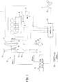
- an output of an internal combustion engine 1 of a vehicle is input into a continuously variable transmission 12 via a torque converter 11.
- the continuously variable transmission 12 includes a primary pulley 13 and a secondary pulley 14, and a V-belt 15 wound around the primary and secondary pulleys 13 and 14.
- the primary pulley 13 changes its contact radius with the V-belt 15 by changing a groove width according to an oil pressure Ppri.
- the secondary pulley 14 changes its contact radius with the V-belt 15 by changing a groove width according to an oil pressure Psec.
- the continuously variable transmission 12 changes a ratio of an input rotation speed and an output rotation speed, i.e. a speed ratio, to continuously variable in accordance with control of the oil pressure Ppri and the oil pressure Psec.
- the oil pressure Ppri and the oil pressure Psec are produced by an oil pressure supply device 16.
- the secondary pulley 14 is connected to a drive wheel via a final gear 18 and a differential 19.
- the internal combustion engine 1 includes an intake throttle device 3 that adjusts an intake air amount.
- the intake throttle device 3 includes an intake throttle 4 provided in an intake passage 2 of the internal combustion engine 1, and an electric motor 5 that changes an opening degree of the intake throttle 4 according to an input signal.
- the oil pressure supply device 16 and the intake throttle device 3 operate according to a command signal output by a controller 21.
- the controller 21 is constituted by a microcomputer including a central processing unit (CPU), a read-only memory (ROM), a random access memory (RAM), and an input/output interface (I/O interface).
- the controller 21 can also be constituted by a plurality of microcomputers.
- Detection signals from a throttle opening degree sensor 6 that detects a throttle opening degree of the intake throttle 4, an accelerator opening degree sensor 22 that detects an accelerator opening degree of an accelerator pedal 7 of the vehicle, an engine rotation speed sensor 23 that detects a rotation speed of the internal combustion engine 1, a primary pulley rotation speed sensor 24 that detects a rotation speed of the primary pulley 13, and a vehicle speed sensor 26 that detects a running speed of the vehicle are input as signals into the controller 21.
- the controller 21 controls a drive force of the vehicle by performing an opening control of the intake throttle 4 and a shift control of the continuously variable transmission 12 via the oil pressure supply device 16 in accordance with the above-mentioned detection signals.
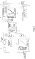
- An acceleration requirement determination unit 30 determines an acceleration requirement by an operator based on a signal from the accelerator opening degree sensor 22. Specifically, the acceleration requirement determination unit 30 determines that acceleration is required if an amount of increase per unit of time of the accelerator opening degree is greater than a first predetermined amount of increase. Also, if the accelerator pedal 7 is depressed further and the accelerator opening degree increases above a predetermined opening degree after a running mode is switched to an acceleration requirement mode to be explained later, the acceleration requirement determination unit 30 determines that further acceleration is required. Multiple predetermined opening degrees are set in stages, and the acceleration requirement determination unit 30 determines that further acceleration is required each time the accelerator pedal 7 is depressed further and the accelerator opening degree increases to reach one of the multiple predetermined opening degrees which are set in stages.
- the acceleration requirement determination unit 30 determines that further acceleration is required when the accelerator pedal 7 is depressed further in the acceleration requirement mode and the accelerator opening degree reaches a certain predetermined opening degree (for example, the first predetermined opening degree), and then determines again that further acceleration is required when the accelerator pedal 7 is depressed further and the accelerator opening degree reaches another certain predetermined opening degree that has been set next (for example, a second predetermined opening degree).
- the acceleration requirement determination unit 30 determines that acceleration is not required if the amount of increase per unit of time of the accelerator opening degree is less than the first predetermined amount of increase.
- the acceleration requirement determination unit 30 determines that acceleration is no longer required if the amount of increase per unit of time of the accelerator opening degree becomes less than the second predetermined amount of increase.
- the second predetermined amount of increase is a value that is smaller than the first predetermined amount of increase, and is, for example, a negative value.
- a mode switching unit 31 switches the running mode of the vehicle to a normal mode or an acceleration requirement mode based on a signal from the acceleration requirement determination unit 30. If it is determined by the acceleration requirement determination unit 30 that acceleration is required, the mode switching unit 31 switches the running mode from the normal mode to the acceleration requirement mode. If it is determined by the acceleration requirement determination unit 30 that acceleration is no longer required, the mode switching unit 31 switches the running mode from the acceleration requirement mode to the normal mode. The mode switching unit 31 maintains the current running mode except in the above-mentioned cases in which it switches the running mode.
- a vehicle speed selecting unit 32 selects a current vehicle speed detected by the vehicle speed sensor 26.
- the vehicle speed selecting unit 32 selects a vehicle speed detected by the vehicle speed sensor 26 at the time of switching to the acceleration requirement mode and maintains this vehicle speed while in the acceleration requirement mode.
- the vehicle speed selecting unit 32 updates the maintained vehicle speed to a vehicle speed detected by the vehicle speed sensor 26 at the time further acceleration was required, and maintains this updated vehicle speed. In other words, while in the acceleration requirement mode, the vehicle speed selecting unit 32 updates the vehicle speed each time further acceleration is required and then maintains the updated vehicle speed.
- An accelerator opening degree correction unit 33 corrects the accelerator opening degree detected by the accelerator opening degree sensor 22 based on a map, and calculates an accelerator opening degree correction value.
- the accelerator opening degree correction value is smaller than the accelerator opening degree before correction.
- An accelerator opening degree selecting unit 34 selects the uncorrected accelerator opening degree or the accelerator opening degree correction value according to the running mode.
- the accelerator opening degree selecting unit 34 selects the uncorrected accelerator opening degree when the running mode is in the normal mode, and selects the accelerator opening degree correction value when the running mode is in the acceleration requirement mode.
- a target drive force setting unit 35 sets the target drive force based on the vehicle speed selected by the vehicle speed selecting unit 32 and the accelerator opening degree selected by the accelerator opening degree selecting unit 34.
- the target drive force setting unit 35 sets the target drive force from a map based on the current vehicle speed detected by the vehicle speed sensor 26 and the uncorrected accelerator opening degree.
- the target drive force setting unit 35 sets the target drive force from a map based on the vehicle speed detected by the vehicle speed sensor 26 at the time of switching to the acceleration requirement mode and the corrected accelerator opening degree.
- the target drive force setting unit 35 sets the target drive force from a map based on the maintained vehicle speed and the corrected accelerator opening degree.
- the vehicle speed is updated from the vehicle speed that was maintained to a vehicle speed detected by the vehicle speed sensor 26 at the time further acceleration was required.
- the target drive force setting unit 35 sets the target drive force from a map based on the updated vehicle speed and the corrected accelerator opening degree.
- an upper limit value of the target drive force is set based on the current vehicle speed and accelerator opening degree. If the target drive force that is set in the acceleration requirement mode is greater than the upper limit value, the target drive force is set to the upper limit value.
- a target output setting unit 36 sets a target output by multiplying the target drive force set by the target drive force setting unit 35 and the current vehicle speed detected by the vehicle speed sensor 26.
- a target engine rotation speed setting unit 37 sets the target engine rotation speed from a map based on the target output.
- a target output rotation speed calculating unit 38 calculates a rotation speed of the secondary pulley 14 of the continuously variable transmission 12 based on the vehicle speed detected by the vehicle speed sensor 26.
- a target speed ratio setting unit 39 sets a target speed ratio by dividing the target engine rotation speed by the rotation speed of the secondary pulley 14.
- a target engine torque setting unit 40 sets a target engine torque by multiplying the target drive force and the radius of the drive wheel and then dividing the resulting value by the target speed ratio and the final gear ratio.
- the continuously variable transmission 12 is controlled based on the target speed ratio set as described above, and the intake throttle 4 is controlled based on the target engine torque set as described above.
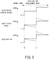
- the accelerator pedal 7 is depressed and acceleration is required, and thus the running mode switches from the normal mode to the acceleration requirement mode. Thereby, the vehicle speed for setting the target drive force is maintained at a vehicle speed at the time of switching to the acceleration requirement mode.
- the accelerator opening degree is constant, and the target drive force is also constant. Also, since the accelerator opening degree and the target drive force are constant, the acceleration of the vehicle is maintained.
- the vehicle speed would increase and the accelerator opening degree would be constant, and thus the target drive force would decrease as shown by the dashed line in FIG. 3 .
- the vehicle acceleration would also decrease.
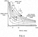
- the above will be explained using the map for setting the target drive force shown in FIG. 4 .
- the running mode is modified from the normal mode to the acceleration requirement mode at a vehicle speed V1 and an accelerator opening degree APO1
- the vehicle speed for setting the target drive force is maintained at the vehicle speed V 1. Therefore, if the accelerator opening degree APO1 is constant, the target drive force stays constant as shown by the arrow A even if the actual vehicle speed increases.
- the target drive force decreases as shown by the arrow B.
- the accelerator pedal 7 is depressed further and further acceleration is required. Thereby, the vehicle speed for setting the target drive force is updated to a vehicle speed at the time further acceleration was required. The target drive force is set based on this updated vehicle speed.
- the running mode is modified from the normal mode to the acceleration requirement mode at the vehicle speed V1 and the accelerator opening degree APO1, and the accelerator pedal 7 is depressed further at the time the actual vehicle speed reaches "V2".
- the accelerator opening degree is then modified from "APO1" to "APO2", and further acceleration is required.
- the target drive force stays constant as shown by the arrow C even if the vehicle speed for setting the target drive force is updated from "V1" to "V2" and then the actual vehicle speed increases.
- the target drive force is set based on the vehicle speed V1 and the accelerator opening degree APO2 and thus becomes a value illustrated by point "a". Therefore, the target drive force stays constant as shown by the arrow D even if the actual vehicle speed increases. However, this target drive force is larger than the upper limit value set based on the current vehicle speed, and thus the target drive force is actually restricted as shown by the arrow E. Therefore, the target drive force decreases as the actual vehicle speed increases, and the acceleration also gradually decreases (the target drive force and the acceleration of the vehicle in this case are illustrated by the dotted lines in FIG. 3 ).
- the acceleration at the time the accelerator pedal 7 is depressed further becomes smaller than the acceleration in the case that the vehicle speed is not updated.
- subsequent decreases in the acceleration can be suppressed, and thus the extension of the acceleration can be maintained.
- the target drive force is set based on the accelerator opening degree and the vehicle speed at the time of mode switching. Therefore, even in the acceleration requirement mode, the target drive force can be set using the map used in the normal mode. Therefore, the target drive force can be set without any complicated calculations, and thus the vehicle can be accelerated.
- the running mode is in the acceleration requirement mode, by maintaining the vehicle speed for setting the target drive force, the target drive force can be inhibited from decreasing together with an increase in the actual vehicle speed.
- the acceleration ability of the vehicle can be improved.
- the target drive force can be set according to the accelerator opening degree, and thus the target drive force can be set according to the depression of the accelerator pedal 7 by an operator and the vehicle can be accelerated.
- the vehicle speed for setting the target drive force is updated to a vehicle speed at the time that further acceleration was required.
- the target drive force can be inhibited from being restricted by the upper limit value, the target drive force and the acceleration can be inhibited from decreasing along with an increase in the vehicle speed, and the extension of the acceleration can be maintained.
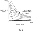
- the accelerator opening degree is corrected so as to be less than the accelerator opening degree in the normal mode, and the target drive force is set using the accelerator opening degree correction value.
- the running mode is in the acceleration requirement mode, for example, an accelerator opening degree APO detected by the accelerator opening degree sensor 22 is corrected to an accelerator opening degree APO' as shown in FIG. 5 .
- the target drive force is inhibited from being restricted by the upper limit value as shown by the dotted line in FIG. 5 , and the target drive force is kept constant as shown by the solid line in FIG. 5 .
- the extension of the acceleration can be maintained.
- the continuously variable transmission 12 mentioned above can be installed in a hybrid vehicle, and a motor can function as a drive source.
Claims (4)
- Fahrzeug-Steuerungsvorrichtung, die umfasst:eine Einrichtung (35) zum Einstellen einer Soll-Antriebskraft, die so ausgeführt ist, dass sie eine Soll-Antriebskraft auf Basis einer Fahrzeuggeschwindigkeit und eines Gaspedal-Öffnungsgrades einstellt;eine Einrichtung (39) zum Einstellen eines Soll-Übersetzungsverhältnisses, die so ausgeführt ist, dass sie ein Soll-Übersetzungsverhältnis eines stufenlosen Getriebes (12) so einstellt, dass die Soll-Antriebskraft realisiert wird; sowieeine Einrichtung (40) zum Einstellen eines Soll-Drehmomentes, die so ausgeführt ist, dass sie ein Soll-Drehmoment einer Antriebsquelle (1) auf Basis der Soll-Antriebskraft und des Übersetzungsverhältnisses einstellt,wobei die Fahrzeug-Steuerungsvorrichtung des Weiteren umfasst:eine Einrichtung (26) zur Erfassung einer Fahrzeug-Geschwindigkeit, die so ausgeführt ist, dass sie eine Fahrzeug-Geschwindigkeit erfasst;eine Einrichtung (22) zur Erfassung eines Gaspedal-Öffnungsgrades, die so ausgeführt ist, dass sie einen Gaspedal-Öffnungsgrad erfasst;eine Einrichtung (30) zur Bestimmung einer Beschleunigungs-Anforderung, die so ausgeführt ist, dass sie eine Beschleunigungs-Anforderung auf Basis des Gaspedal-Öffnungsgrades bestimmt;eine Einrichtung (31) zum Umschalten eines Modus, die so ausgeführt ist, dass sie einen Fahr-Modus auf Basis der Beschleunigungs-Anforderung auf einen Normal-Modus oder einen Beschleunigungs-Anforderungs-Modus umschaltet,dadurch gekennzeichnet, dass
die Einrichtung (35) zum Einstellen einer Soll-Antriebskraft so ausgeführt ist, dass sie, wenn der Fahr-Modus von dem Normal-Modus auf den Beschleunigungs-Anforderungs-Modus umgeschaltet wird, die Fahrzeug-Geschwindigkeit zum Zeitpunkt des Umschaltens von dem Normal-Modus auf den Beschleunigungs-Anforderungs-Modus als eine beibehaltene Fahrzeug-Geschwindigkeit beibehält, bis der Fahr-Modus wieder auf den Normal-Modus umgestellt wird, und die Soll-Antriebskraft auf Basis des Gaspedal-Öffnungsgrades sowie der beibehaltenen Fahrzeug-Geschwindigkeit einstellt. - Fahrzeug-Steuerungsvorrichtung nach Anspruch 1, wobei die Einrichtung (30) zur Bestimmung einer Beschleunigungs-Anforderung so ausgeführt ist, dass sie, wenn der Gaspedal-Öffnungsgrad nach Eintritt in den Beschleunigungs-Anforderungs-Modus über einen vorgegebenen Öffnungsgrad hinaus zunimmt, bestimmt, dass weitere Beschleunigung angefordert wird, und
die Einrichtung (35) zum Einstellen einer Soll-Antriebskraft so ausgeführt ist, dass sie, wenn im Beschleunigungs-Anforderungs-Modus die weitere Beschleunigung angefordert wird, die beibehaltene Fahrzeug-Geschwindigkeit auf eine Fahrzeug-Geschwindigkeit zu dem Zeitpunkt aktualisiert, zu dem die weitere Beschleunigung angefordert wurde, und sie die Soll-Antriebskraft auf Basis des Gaspedal-Öffnungsgrades sowie der aktualisierten beibehaltenen Fahrzeuggeschwindigkeit einstellt. - Fahrzeug-Steuerungsvorrichtung nach Anspruch 1 oder Anspruch 2, die des Weiteren eine Einrichtung (33) zur Korrektur eines Gaspedal-Öffnungsgrades umfasst, die so ausgeführt ist, dass sie einen Korrekturwert für den Gaspedal-Öffnungsgrad in dem Beschleunigungs-Anforderungs-Modus berechnet, indem sie den durch die Einrichtung (22) zur Erfassung eines Gaspedal-Öffnungsgrades erfassten Gaspedal-Öffnungsgrad reduzierend korrigiert,
wobei die Einrichtung (35) zum Einstellen einer Soll-Antriebskraft die Soll-Antriebskraft auf Basis des Korrekturwertes für den Gaspedal-Öffnungsgrad und der beibehaltenen Fahrzeug-Geschwindigkeit einstellt. - Verfahren zum Steuern eines Fahrzeugs, das umfasst
Einstellen einer Soll-Antriebskraft auf Basis einer Fahrzeug-Geschwindigkeit und eines Gaspedal-Öffnungsgrades;
Einstellen eines Soll-Übersetzungsverhältnisses eines stufenlosen Getriebes (12), um die Soll-Antriebskraft zu realisieren; und
Einstellen eines Soll-Drehmomentes einer Antriebsquelle (1) auf Basis der Soll-Antriebskraft und des Übersetzungsverhältnisses,
wobei das Verfahren zum Steuern des Fahrzeugs des Weiteren umfasst:Erfassen einer Fahrzeug-Geschwindigkeit;Erfassen eines Gaspedal-Öffnungsgrades;Bestimmen einer Beschleunigungs-Anforderung auf Basis des Gaspedal-Öffnungsgrades; undUmschalten eines Fahr-Modus auf einen Normal-Modus oder einen Beschleunigungs-Anforderungs-Modus auf Basis der Beschleunigungs-Anforderung,dadurch gekennzeichnet, dass
wenn der Fahr-Modus von dem Normal-Modus auf den Beschleunigungs-Anforderungs-Modus umgeschaltet wird, die Fahrzeug-Geschwindigkeit zum Zeitpunkt des Umschaltens von dem Normal-Modus auf den Beschleunigungs-Anforderungs-Modus als eine beibehaltene Fahrzeug-Geschwindigkeit beibehalten wird, bis der Fahr-Modus wieder auf den Normal-Modus umgestellt wird, und die Soll-Antriebskraft auf Basis des Gaspedal-Öffnungsgrades sowie der beibehaltenen Fahrzeug-Geschwindigkeit eingestellt wird.
Applications Claiming Priority (2)
| Application Number | Priority Date | Filing Date | Title |
|---|---|---|---|
| JP2012205885 | 2012-09-19 | ||
| PCT/JP2013/069625 WO2014045697A1 (ja) | 2012-09-19 | 2013-07-19 | 車両制御装置および車両の制御方法 |
Publications (3)
| Publication Number | Publication Date |
|---|---|
| EP2899084A1 EP2899084A1 (de) | 2015-07-29 |
| EP2899084A4 EP2899084A4 (de) | 2016-02-24 |
| EP2899084B1 true EP2899084B1 (de) | 2017-02-22 |
Family
ID=50341023
Family Applications (1)
| Application Number | Title | Priority Date | Filing Date |
|---|---|---|---|
| EP13839773.2A Active EP2899084B1 (de) | 2012-09-19 | 2013-07-19 | Fahrzeugsteuerungsvorrichtung und verfahren zur steuerung eines fahrzeugs |
Country Status (5)
| Country | Link |
|---|---|
| US (1) | US9376113B2 (de) |
| EP (1) | EP2899084B1 (de) |
| JP (1) | JP5967207B2 (de) |
| CN (1) | CN104619567B (de) |
| WO (1) | WO2014045697A1 (de) |
Families Citing this family (6)
| Publication number | Priority date | Publication date | Assignee | Title |
|---|---|---|---|---|
| JP6540660B2 (ja) * | 2016-04-15 | 2019-07-10 | トヨタ自動車株式会社 | 内燃機関のデータ記録装置 |
| JP7091816B2 (ja) * | 2018-05-08 | 2022-06-28 | トヨタ自動車株式会社 | 駆動力制御装置 |
| JP2020169580A (ja) * | 2019-04-01 | 2020-10-15 | トヨタ自動車株式会社 | 車両の駆動力制御装置 |
| CN110469661B (zh) * | 2019-07-30 | 2020-06-30 | 武汉理工大学 | 一种基于cvt效率的动力性速比优化方法及系统 |
| CN114258364A (zh) * | 2021-05-20 | 2022-03-29 | 浙江吉利控股集团有限公司 | 一种混合动力车辆的请求驱动力的确定方法及装置 |
| CN113428166A (zh) * | 2021-07-31 | 2021-09-24 | 重庆长安汽车股份有限公司 | 一种车辆驾驶模式控制方法、系统和车辆 |
Family Cites Families (21)
| Publication number | Priority date | Publication date | Assignee | Title |
|---|---|---|---|---|
| US6066070A (en) * | 1998-04-28 | 2000-05-23 | Toyota Jidosha Kabushiki Kaisha | Control system of vehicle having continuously variable transmission |
| JP3438589B2 (ja) * | 1998-06-04 | 2003-08-18 | 日産自動車株式会社 | 車両の駆動力制御装置 |
| JP3539335B2 (ja) * | 2000-03-10 | 2004-07-07 | トヨタ自動車株式会社 | 無段変速機を備えた車両の制御装置 |
| JP2001330133A (ja) * | 2000-05-22 | 2001-11-30 | Jatco Transtechnology Ltd | 駆動力制御装置 |
| JP3666391B2 (ja) * | 2000-12-26 | 2005-06-29 | 日産自動車株式会社 | 駆動力制御装置 |
| JP3580260B2 (ja) * | 2001-03-01 | 2004-10-20 | 日産自動車株式会社 | 車両の制御装置 |
| JP2002274353A (ja) * | 2001-03-16 | 2002-09-25 | Nissan Motor Co Ltd | 車両用制駆動力制御装置 |
| JP4200952B2 (ja) | 2004-08-09 | 2008-12-24 | トヨタ自動車株式会社 | 無段変速機を備えた車両の制御装置 |
| JP4353154B2 (ja) * | 2005-08-04 | 2009-10-28 | トヨタ自動車株式会社 | 燃料電池自動車 |
| JP4462170B2 (ja) * | 2005-11-07 | 2010-05-12 | 日産自動車株式会社 | ハイブリッド車両のエンジン始動制御装置 |
| JP4529940B2 (ja) * | 2006-05-02 | 2010-08-25 | 日産自動車株式会社 | ハイブリッド車両の伝動状態切り替え制御装置 |
| JP4823762B2 (ja) * | 2006-05-23 | 2011-11-24 | 富士重工業株式会社 | 車両の出力制御装置 |
| JP4306713B2 (ja) * | 2006-10-20 | 2009-08-05 | トヨタ自動車株式会社 | 車両の制御装置、制御方法、その制御方法をコンピュータで実現するプログラムおよびそのプログラムを記録した記録媒体 |
| JP2009101910A (ja) | 2007-10-24 | 2009-05-14 | Toyota Motor Corp | 車両の制御装置 |
| US8285431B2 (en) * | 2007-11-03 | 2012-10-09 | GM Global Technology Operations LLC | Optimal selection of hybrid range state and/or input speed with a blended braking system in a hybrid electric vehicle |
| JP2010155522A (ja) * | 2008-12-26 | 2010-07-15 | Hitachi Automotive Systems Ltd | 車両走行制御装置 |
| US8224549B2 (en) * | 2009-09-17 | 2012-07-17 | GM Global Technology Operations LLC | Method and system for controlling vehicle functions in response to at least one of grade, trailering, and heavy load |
| JP4633198B1 (ja) * | 2009-12-15 | 2011-02-23 | 日産自動車株式会社 | 車両用ベルト式無段変速機の制御装置と制御方法 |
| JP5510227B2 (ja) * | 2010-09-15 | 2014-06-04 | トヨタ自動車株式会社 | 車両制御装置 |
| MY170394A (en) * | 2011-09-07 | 2019-07-27 | Nissan Motor | Control device for continuously variable transmission and control method for continuosly variable transmission |
| JP5375913B2 (ja) * | 2011-09-22 | 2013-12-25 | トヨタ自動車株式会社 | ハイブリッド車の制御装置 |
-
2013
- 2013-07-19 CN CN201380047406.9A patent/CN104619567B/zh active Active
- 2013-07-19 EP EP13839773.2A patent/EP2899084B1/de active Active
- 2013-07-19 US US14/428,789 patent/US9376113B2/en active Active
- 2013-07-19 JP JP2014536647A patent/JP5967207B2/ja active Active
- 2013-07-19 WO PCT/JP2013/069625 patent/WO2014045697A1/ja active Application Filing
Non-Patent Citations (1)
| Title |
|---|
| None * |
Also Published As
| Publication number | Publication date |
|---|---|
| CN104619567A (zh) | 2015-05-13 |
| CN104619567B (zh) | 2017-03-08 |
| EP2899084A4 (de) | 2016-02-24 |
| US9376113B2 (en) | 2016-06-28 |
| JPWO2014045697A1 (ja) | 2016-08-18 |
| JP5967207B2 (ja) | 2016-08-10 |
| US20150224993A1 (en) | 2015-08-13 |
| EP2899084A1 (de) | 2015-07-29 |
| WO2014045697A1 (ja) | 2014-03-27 |
Similar Documents
| Publication | Publication Date | Title |
|---|---|---|
| EP2899084B1 (de) | Fahrzeugsteuerungsvorrichtung und verfahren zur steuerung eines fahrzeugs | |
| JP5388303B2 (ja) | 無段変速機の変速制御装置 | |
| JP6004003B2 (ja) | 車両制御装置及びその制御方法 | |
| US9429229B2 (en) | Shift control device for continuously variable transmission | |
| US9810320B2 (en) | Vehicle control system | |
| JP2008239130A (ja) | 車両の制御装置 | |
| JP5594193B2 (ja) | 運転支援装置 | |
| EP2862763B1 (de) | Antriebskraftsteuerungsvorrichtung für ein fahrzeug | |
| EP2899085B1 (de) | Fahrzeugsteuerungsvorrichtung und fahrzeugsteuerungsverfahren | |
| EP2754925B1 (de) | Steuervorrichtung für ein kontinuierlich variables getriebe | |
| US9290175B2 (en) | Vehicle control system | |
| KR101989352B1 (ko) | 스타팅 절차 동안 자동차의 구동 트레인에서 자동식 마찰 클러치를 제어하는 방법 | |
| KR20130054052A (ko) | 차량의 엔진토크 제어장치 및 방법 | |
| JP2007176321A (ja) | 車両の制御装置 | |
| JP4977833B2 (ja) | 自動変速機の変速速度制御装置 | |
| JP2017115935A (ja) | 車両の変速制御装置 | |
| JP2015202771A (ja) | 車両用制御装置 | |
| EP2738428A1 (de) | Wechselgetriebevorrichtung für ein stufenloses getriebe | |
| KR101421372B1 (ko) | 오토크루즈 제어방법 | |
| JP5234295B2 (ja) | 自動変速機制御装置 | |
| KR20180009541A (ko) | 차량의 메누버링 모드 주행을 위한 제어방법 | |
| KR20180001746A (ko) | 자동변속기의 유압 제어방법 | |
| JP2007192098A (ja) | エンジン制御装置及びエンジン制御方法 | |
| KR20190001620A (ko) | 무단변속기 차량의 기어비 제어방법 | |
| JP2007112238A (ja) | 車両の駆動力制御装置 |
Legal Events
| Date | Code | Title | Description |
|---|---|---|---|
| PUAI | Public reference made under article 153(3) epc to a published international application that has entered the european phase |
Free format text: ORIGINAL CODE: 0009012 |
|
| 17P | Request for examination filed |
Effective date: 20150409 |
|
| AK | Designated contracting states |
Kind code of ref document: A1 Designated state(s): AL AT BE BG CH CY CZ DE DK EE ES FI FR GB GR HR HU IE IS IT LI LT LU LV MC MK MT NL NO PL PT RO RS SE SI SK SM TR |
|
| AX | Request for extension of the european patent |
Extension state: BA ME |
|
| DAX | Request for extension of the european patent (deleted) | ||
| RA4 | Supplementary search report drawn up and despatched (corrected) |
Effective date: 20160125 |
|
| RIC1 | Information provided on ipc code assigned before grant |
Ipc: F02D 29/00 20060101ALI20160119BHEP Ipc: B60W 10/06 20060101ALI20160119BHEP Ipc: F16H 61/02 20060101ALI20160119BHEP Ipc: F16H 61/662 20060101ALI20160119BHEP Ipc: B60W 30/182 20120101AFI20160119BHEP Ipc: B60W 10/107 20120101ALI20160119BHEP |
|
| GRAP | Despatch of communication of intention to grant a patent |
Free format text: ORIGINAL CODE: EPIDOSNIGR1 |
|
| INTG | Intention to grant announced |
Effective date: 20161111 |
|
| RIN1 | Information on inventor provided before grant (corrected) |
Inventor name: IRIYAMA, MASAHIRO Inventor name: YOSHINO, TAKAHIRO Inventor name: ONO, MASASHI |
|
| GRAS | Grant fee paid |
Free format text: ORIGINAL CODE: EPIDOSNIGR3 |
|
| RAP1 | Party data changed (applicant data changed or rights of an application transferred) |
Owner name: NISSAN MOTOR CO., LTD. |
|
| RIN1 | Information on inventor provided before grant (corrected) |
Inventor name: ONO, MASASHI Inventor name: YOSHINO, TAKAHIRO Inventor name: IRIYAMA, MASAHIRO |
|
| GRAA | (expected) grant |
Free format text: ORIGINAL CODE: 0009210 |
|
| AK | Designated contracting states |
Kind code of ref document: B1 Designated state(s): AL AT BE BG CH CY CZ DE DK EE ES FI FR GB GR HR HU IE IS IT LI LT LU LV MC MK MT NL NO PL PT RO RS SE SI SK SM TR |
|
| REG | Reference to a national code |
Ref country code: GB Ref legal event code: FG4D |
|
| REG | Reference to a national code |
Ref country code: CH Ref legal event code: EP |
|
| REG | Reference to a national code |
Ref country code: AT Ref legal event code: REF Ref document number: 869032 Country of ref document: AT Kind code of ref document: T Effective date: 20170315 |
|
| REG | Reference to a national code |
Ref country code: IE Ref legal event code: FG4D |
|
| REG | Reference to a national code |
Ref country code: DE Ref legal event code: R096 Ref document number: 602013017819 Country of ref document: DE |
|
| REG | Reference to a national code |
Ref country code: LT Ref legal event code: MG4D |
|
| REG | Reference to a national code |
Ref country code: NL Ref legal event code: MP Effective date: 20170222 |
|
| REG | Reference to a national code |
Ref country code: AT Ref legal event code: MK05 Ref document number: 869032 Country of ref document: AT Kind code of ref document: T Effective date: 20170222 |
|
| REG | Reference to a national code |
Ref country code: FR Ref legal event code: PLFP Year of fee payment: 5 |
|
| PG25 | Lapsed in a contracting state [announced via postgrant information from national office to epo] |
Ref country code: NO Free format text: LAPSE BECAUSE OF FAILURE TO SUBMIT A TRANSLATION OF THE DESCRIPTION OR TO PAY THE FEE WITHIN THE PRESCRIBED TIME-LIMIT Effective date: 20170522 Ref country code: HR Free format text: LAPSE BECAUSE OF FAILURE TO SUBMIT A TRANSLATION OF THE DESCRIPTION OR TO PAY THE FEE WITHIN THE PRESCRIBED TIME-LIMIT Effective date: 20170222 Ref country code: GR Free format text: LAPSE BECAUSE OF FAILURE TO SUBMIT A TRANSLATION OF THE DESCRIPTION OR TO PAY THE FEE WITHIN THE PRESCRIBED TIME-LIMIT Effective date: 20170523 Ref country code: LT Free format text: LAPSE BECAUSE OF FAILURE TO SUBMIT A TRANSLATION OF THE DESCRIPTION OR TO PAY THE FEE WITHIN THE PRESCRIBED TIME-LIMIT Effective date: 20170222 Ref country code: FI Free format text: LAPSE BECAUSE OF FAILURE TO SUBMIT A TRANSLATION OF THE DESCRIPTION OR TO PAY THE FEE WITHIN THE PRESCRIBED TIME-LIMIT Effective date: 20170222 |
|
| PG25 | Lapsed in a contracting state [announced via postgrant information from national office to epo] |
Ref country code: LV Free format text: LAPSE BECAUSE OF FAILURE TO SUBMIT A TRANSLATION OF THE DESCRIPTION OR TO PAY THE FEE WITHIN THE PRESCRIBED TIME-LIMIT Effective date: 20170222 Ref country code: BG Free format text: LAPSE BECAUSE OF FAILURE TO SUBMIT A TRANSLATION OF THE DESCRIPTION OR TO PAY THE FEE WITHIN THE PRESCRIBED TIME-LIMIT Effective date: 20170522 Ref country code: SE Free format text: LAPSE BECAUSE OF FAILURE TO SUBMIT A TRANSLATION OF THE DESCRIPTION OR TO PAY THE FEE WITHIN THE PRESCRIBED TIME-LIMIT Effective date: 20170222 Ref country code: PT Free format text: LAPSE BECAUSE OF FAILURE TO SUBMIT A TRANSLATION OF THE DESCRIPTION OR TO PAY THE FEE WITHIN THE PRESCRIBED TIME-LIMIT Effective date: 20170622 Ref country code: ES Free format text: LAPSE BECAUSE OF FAILURE TO SUBMIT A TRANSLATION OF THE DESCRIPTION OR TO PAY THE FEE WITHIN THE PRESCRIBED TIME-LIMIT Effective date: 20170222 Ref country code: RS Free format text: LAPSE BECAUSE OF FAILURE TO SUBMIT A TRANSLATION OF THE DESCRIPTION OR TO PAY THE FEE WITHIN THE PRESCRIBED TIME-LIMIT Effective date: 20170222 Ref country code: AT Free format text: LAPSE BECAUSE OF FAILURE TO SUBMIT A TRANSLATION OF THE DESCRIPTION OR TO PAY THE FEE WITHIN THE PRESCRIBED TIME-LIMIT Effective date: 20170222 Ref country code: NL Free format text: LAPSE BECAUSE OF FAILURE TO SUBMIT A TRANSLATION OF THE DESCRIPTION OR TO PAY THE FEE WITHIN THE PRESCRIBED TIME-LIMIT Effective date: 20170222 |
|
| PG25 | Lapsed in a contracting state [announced via postgrant information from national office to epo] |
Ref country code: EE Free format text: LAPSE BECAUSE OF FAILURE TO SUBMIT A TRANSLATION OF THE DESCRIPTION OR TO PAY THE FEE WITHIN THE PRESCRIBED TIME-LIMIT Effective date: 20170222 Ref country code: RO Free format text: LAPSE BECAUSE OF FAILURE TO SUBMIT A TRANSLATION OF THE DESCRIPTION OR TO PAY THE FEE WITHIN THE PRESCRIBED TIME-LIMIT Effective date: 20170222 Ref country code: CZ Free format text: LAPSE BECAUSE OF FAILURE TO SUBMIT A TRANSLATION OF THE DESCRIPTION OR TO PAY THE FEE WITHIN THE PRESCRIBED TIME-LIMIT Effective date: 20170222 Ref country code: IT Free format text: LAPSE BECAUSE OF FAILURE TO SUBMIT A TRANSLATION OF THE DESCRIPTION OR TO PAY THE FEE WITHIN THE PRESCRIBED TIME-LIMIT Effective date: 20170222 Ref country code: SK Free format text: LAPSE BECAUSE OF FAILURE TO SUBMIT A TRANSLATION OF THE DESCRIPTION OR TO PAY THE FEE WITHIN THE PRESCRIBED TIME-LIMIT Effective date: 20170222 |
|
| REG | Reference to a national code |
Ref country code: DE Ref legal event code: R097 Ref document number: 602013017819 Country of ref document: DE |
|
| PG25 | Lapsed in a contracting state [announced via postgrant information from national office to epo] |
Ref country code: PL Free format text: LAPSE BECAUSE OF FAILURE TO SUBMIT A TRANSLATION OF THE DESCRIPTION OR TO PAY THE FEE WITHIN THE PRESCRIBED TIME-LIMIT Effective date: 20170222 Ref country code: DK Free format text: LAPSE BECAUSE OF FAILURE TO SUBMIT A TRANSLATION OF THE DESCRIPTION OR TO PAY THE FEE WITHIN THE PRESCRIBED TIME-LIMIT Effective date: 20170222 Ref country code: SM Free format text: LAPSE BECAUSE OF FAILURE TO SUBMIT A TRANSLATION OF THE DESCRIPTION OR TO PAY THE FEE WITHIN THE PRESCRIBED TIME-LIMIT Effective date: 20170222 |
|
| PLBE | No opposition filed within time limit |
Free format text: ORIGINAL CODE: 0009261 |
|
| STAA | Information on the status of an ep patent application or granted ep patent |
Free format text: STATUS: NO OPPOSITION FILED WITHIN TIME LIMIT |
|
| 26N | No opposition filed |
Effective date: 20171123 |
|
| PG25 | Lapsed in a contracting state [announced via postgrant information from national office to epo] |
Ref country code: SI Free format text: LAPSE BECAUSE OF FAILURE TO SUBMIT A TRANSLATION OF THE DESCRIPTION OR TO PAY THE FEE WITHIN THE PRESCRIBED TIME-LIMIT Effective date: 20170222 |
|
| REG | Reference to a national code |
Ref country code: CH Ref legal event code: PL |
|
| REG | Reference to a national code |
Ref country code: IE Ref legal event code: MM4A |
|
| PG25 | Lapsed in a contracting state [announced via postgrant information from national office to epo] |
Ref country code: CH Free format text: LAPSE BECAUSE OF NON-PAYMENT OF DUE FEES Effective date: 20170731 Ref country code: IE Free format text: LAPSE BECAUSE OF NON-PAYMENT OF DUE FEES Effective date: 20170719 Ref country code: LI Free format text: LAPSE BECAUSE OF NON-PAYMENT OF DUE FEES Effective date: 20170731 |
|
| REG | Reference to a national code |
Ref country code: BE Ref legal event code: MM Effective date: 20170731 |
|
| REG | Reference to a national code |
Ref country code: FR Ref legal event code: PLFP Year of fee payment: 6 |
|
| PG25 | Lapsed in a contracting state [announced via postgrant information from national office to epo] |
Ref country code: LU Free format text: LAPSE BECAUSE OF NON-PAYMENT OF DUE FEES Effective date: 20170719 |
|
| PG25 | Lapsed in a contracting state [announced via postgrant information from national office to epo] |
Ref country code: BE Free format text: LAPSE BECAUSE OF NON-PAYMENT OF DUE FEES Effective date: 20170731 |
|
| PG25 | Lapsed in a contracting state [announced via postgrant information from national office to epo] |
Ref country code: MT Free format text: LAPSE BECAUSE OF NON-PAYMENT OF DUE FEES Effective date: 20170719 |
|
| PG25 | Lapsed in a contracting state [announced via postgrant information from national office to epo] |
Ref country code: HU Free format text: LAPSE BECAUSE OF FAILURE TO SUBMIT A TRANSLATION OF THE DESCRIPTION OR TO PAY THE FEE WITHIN THE PRESCRIBED TIME-LIMIT; INVALID AB INITIO Effective date: 20130719 Ref country code: MC Free format text: LAPSE BECAUSE OF FAILURE TO SUBMIT A TRANSLATION OF THE DESCRIPTION OR TO PAY THE FEE WITHIN THE PRESCRIBED TIME-LIMIT Effective date: 20170222 |
|
| PG25 | Lapsed in a contracting state [announced via postgrant information from national office to epo] |
Ref country code: CY Free format text: LAPSE BECAUSE OF FAILURE TO SUBMIT A TRANSLATION OF THE DESCRIPTION OR TO PAY THE FEE WITHIN THE PRESCRIBED TIME-LIMIT Effective date: 20170222 |
|
| PG25 | Lapsed in a contracting state [announced via postgrant information from national office to epo] |
Ref country code: MK Free format text: LAPSE BECAUSE OF FAILURE TO SUBMIT A TRANSLATION OF THE DESCRIPTION OR TO PAY THE FEE WITHIN THE PRESCRIBED TIME-LIMIT Effective date: 20170222 |
|
| PG25 | Lapsed in a contracting state [announced via postgrant information from national office to epo] |
Ref country code: TR Free format text: LAPSE BECAUSE OF FAILURE TO SUBMIT A TRANSLATION OF THE DESCRIPTION OR TO PAY THE FEE WITHIN THE PRESCRIBED TIME-LIMIT Effective date: 20170222 |
|
| PG25 | Lapsed in a contracting state [announced via postgrant information from national office to epo] |
Ref country code: AL Free format text: LAPSE BECAUSE OF FAILURE TO SUBMIT A TRANSLATION OF THE DESCRIPTION OR TO PAY THE FEE WITHIN THE PRESCRIBED TIME-LIMIT Effective date: 20170222 Ref country code: IS Free format text: LAPSE BECAUSE OF FAILURE TO SUBMIT A TRANSLATION OF THE DESCRIPTION OR TO PAY THE FEE WITHIN THE PRESCRIBED TIME-LIMIT Effective date: 20170622 |
|
| PGFP | Annual fee paid to national office [announced via postgrant information from national office to epo] |
Ref country code: FR Payment date: 20230621 Year of fee payment: 11 |
|
| PGFP | Annual fee paid to national office [announced via postgrant information from national office to epo] |
Ref country code: GB Payment date: 20230620 Year of fee payment: 11 |
|
| PGFP | Annual fee paid to national office [announced via postgrant information from national office to epo] |
Ref country code: DE Payment date: 20230620 Year of fee payment: 11 |