EP2896683A1 - Zusammensetzung zur verwendung bei der herstellung eines festen beschichtungsfilms und verschraubbare rohrverbindung - Google Patents
Zusammensetzung zur verwendung bei der herstellung eines festen beschichtungsfilms und verschraubbare rohrverbindung Download PDFInfo
- Publication number
- EP2896683A1 EP2896683A1 EP13836965.7A EP13836965A EP2896683A1 EP 2896683 A1 EP2896683 A1 EP 2896683A1 EP 13836965 A EP13836965 A EP 13836965A EP 2896683 A1 EP2896683 A1 EP 2896683A1
- Authority
- EP
- European Patent Office
- Prior art keywords
- solid coating
- coating
- composition
- threaded joint
- plating
- Prior art date
- Legal status (The legal status is an assumption and is not a legal conclusion. Google has not performed a legal analysis and makes no representation as to the accuracy of the status listed.)
- Granted
Links
Images


Classifications
-
- C—CHEMISTRY; METALLURGY
- C09—DYES; PAINTS; POLISHES; NATURAL RESINS; ADHESIVES; COMPOSITIONS NOT OTHERWISE PROVIDED FOR; APPLICATIONS OF MATERIALS NOT OTHERWISE PROVIDED FOR
- C09D—COATING COMPOSITIONS, e.g. PAINTS, VARNISHES OR LACQUERS; FILLING PASTES; CHEMICAL PAINT OR INK REMOVERS; INKS; CORRECTING FLUIDS; WOODSTAINS; PASTES OR SOLIDS FOR COLOURING OR PRINTING; USE OF MATERIALS THEREFOR
- C09D179/00—Coating compositions based on macromolecular compounds obtained by reactions forming in the main chain of the macromolecule a linkage containing nitrogen, with or without oxygen, or carbon only, not provided for in groups C09D161/00 - C09D177/00
- C09D179/04—Polycondensates having nitrogen-containing heterocyclic rings in the main chain; Polyhydrazides; Polyamide acids or similar polyimide precursors
- C09D179/08—Polyimides; Polyester-imides; Polyamide-imides; Polyamide acids or similar polyimide precursors
-
- C—CHEMISTRY; METALLURGY
- C08—ORGANIC MACROMOLECULAR COMPOUNDS; THEIR PREPARATION OR CHEMICAL WORKING-UP; COMPOSITIONS BASED THEREON
- C08G—MACROMOLECULAR COMPOUNDS OBTAINED OTHERWISE THAN BY REACTIONS ONLY INVOLVING UNSATURATED CARBON-TO-CARBON BONDS
- C08G73/00—Macromolecular compounds obtained by reactions forming a linkage containing nitrogen with or without oxygen or carbon in the main chain of the macromolecule, not provided for in groups C08G12/00 - C08G71/00
- C08G73/02—Polyamines
- C08G73/028—Polyamidoamines
-
- C—CHEMISTRY; METALLURGY
- C08—ORGANIC MACROMOLECULAR COMPOUNDS; THEIR PREPARATION OR CHEMICAL WORKING-UP; COMPOSITIONS BASED THEREON
- C08K—Use of inorganic or non-macromolecular organic substances as compounding ingredients
- C08K5/00—Use of organic ingredients
- C08K5/36—Sulfur-, selenium-, or tellurium-containing compounds
- C08K5/41—Compounds containing sulfur bound to oxygen
-
- C—CHEMISTRY; METALLURGY
- C09—DYES; PAINTS; POLISHES; NATURAL RESINS; ADHESIVES; COMPOSITIONS NOT OTHERWISE PROVIDED FOR; APPLICATIONS OF MATERIALS NOT OTHERWISE PROVIDED FOR
- C09D—COATING COMPOSITIONS, e.g. PAINTS, VARNISHES OR LACQUERS; FILLING PASTES; CHEMICAL PAINT OR INK REMOVERS; INKS; CORRECTING FLUIDS; WOODSTAINS; PASTES OR SOLIDS FOR COLOURING OR PRINTING; USE OF MATERIALS THEREFOR
- C09D127/00—Coating compositions based on homopolymers or copolymers of compounds having one or more unsaturated aliphatic radicals, each having only one carbon-to-carbon double bond, and at least one being terminated by a halogen; Coating compositions based on derivatives of such polymers
- C09D127/02—Coating compositions based on homopolymers or copolymers of compounds having one or more unsaturated aliphatic radicals, each having only one carbon-to-carbon double bond, and at least one being terminated by a halogen; Coating compositions based on derivatives of such polymers not modified by chemical after-treatment
- C09D127/12—Coating compositions based on homopolymers or copolymers of compounds having one or more unsaturated aliphatic radicals, each having only one carbon-to-carbon double bond, and at least one being terminated by a halogen; Coating compositions based on derivatives of such polymers not modified by chemical after-treatment containing fluorine atoms
- C09D127/18—Homopolymers or copolymers of tetrafluoroethene
-
- C—CHEMISTRY; METALLURGY
- C09—DYES; PAINTS; POLISHES; NATURAL RESINS; ADHESIVES; COMPOSITIONS NOT OTHERWISE PROVIDED FOR; APPLICATIONS OF MATERIALS NOT OTHERWISE PROVIDED FOR
- C09D—COATING COMPOSITIONS, e.g. PAINTS, VARNISHES OR LACQUERS; FILLING PASTES; CHEMICAL PAINT OR INK REMOVERS; INKS; CORRECTING FLUIDS; WOODSTAINS; PASTES OR SOLIDS FOR COLOURING OR PRINTING; USE OF MATERIALS THEREFOR
- C09D163/00—Coating compositions based on epoxy resins; Coating compositions based on derivatives of epoxy resins
-
- C—CHEMISTRY; METALLURGY
- C09—DYES; PAINTS; POLISHES; NATURAL RESINS; ADHESIVES; COMPOSITIONS NOT OTHERWISE PROVIDED FOR; APPLICATIONS OF MATERIALS NOT OTHERWISE PROVIDED FOR
- C09D—COATING COMPOSITIONS, e.g. PAINTS, VARNISHES OR LACQUERS; FILLING PASTES; CHEMICAL PAINT OR INK REMOVERS; INKS; CORRECTING FLUIDS; WOODSTAINS; PASTES OR SOLIDS FOR COLOURING OR PRINTING; USE OF MATERIALS THEREFOR
- C09D179/00—Coating compositions based on macromolecular compounds obtained by reactions forming in the main chain of the macromolecule a linkage containing nitrogen, with or without oxygen, or carbon only, not provided for in groups C09D161/00 - C09D177/00
- C09D179/02—Polyamines
-
- C—CHEMISTRY; METALLURGY
- C10—PETROLEUM, GAS OR COKE INDUSTRIES; TECHNICAL GASES CONTAINING CARBON MONOXIDE; FUELS; LUBRICANTS; PEAT
- C10M—LUBRICATING COMPOSITIONS; USE OF CHEMICAL SUBSTANCES EITHER ALONE OR AS LUBRICATING INGREDIENTS IN A LUBRICATING COMPOSITION
- C10M173/00—Lubricating compositions containing more than 10% water
- C10M173/02—Lubricating compositions containing more than 10% water not containing mineral or fatty oils
-
- F—MECHANICAL ENGINEERING; LIGHTING; HEATING; WEAPONS; BLASTING
- F16—ENGINEERING ELEMENTS AND UNITS; GENERAL MEASURES FOR PRODUCING AND MAINTAINING EFFECTIVE FUNCTIONING OF MACHINES OR INSTALLATIONS; THERMAL INSULATION IN GENERAL
- F16L—PIPES; JOINTS OR FITTINGS FOR PIPES; SUPPORTS FOR PIPES, CABLES OR PROTECTIVE TUBING; MEANS FOR THERMAL INSULATION IN GENERAL
- F16L15/00—Screw-threaded joints; Forms of screw-threads for such joints
- F16L15/04—Screw-threaded joints; Forms of screw-threads for such joints with additional sealings
-
- F—MECHANICAL ENGINEERING; LIGHTING; HEATING; WEAPONS; BLASTING
- F16—ENGINEERING ELEMENTS AND UNITS; GENERAL MEASURES FOR PRODUCING AND MAINTAINING EFFECTIVE FUNCTIONING OF MACHINES OR INSTALLATIONS; THERMAL INSULATION IN GENERAL
- F16L—PIPES; JOINTS OR FITTINGS FOR PIPES; SUPPORTS FOR PIPES, CABLES OR PROTECTIVE TUBING; MEANS FOR THERMAL INSULATION IN GENERAL
- F16L58/00—Protection of pipes or pipe fittings against corrosion or incrustation
- F16L58/18—Protection of pipes or pipe fittings against corrosion or incrustation specially adapted for pipe fittings
- F16L58/182—Protection of pipes or pipe fittings against corrosion or incrustation specially adapted for pipe fittings for screw-threaded joints
-
- C—CHEMISTRY; METALLURGY
- C08—ORGANIC MACROMOLECULAR COMPOUNDS; THEIR PREPARATION OR CHEMICAL WORKING-UP; COMPOSITIONS BASED THEREON
- C08K—Use of inorganic or non-macromolecular organic substances as compounding ingredients
- C08K3/00—Use of inorganic substances as compounding ingredients
- C08K3/02—Elements
- C08K3/04—Carbon
-
- C—CHEMISTRY; METALLURGY
- C10—PETROLEUM, GAS OR COKE INDUSTRIES; TECHNICAL GASES CONTAINING CARBON MONOXIDE; FUELS; LUBRICANTS; PEAT
- C10M—LUBRICATING COMPOSITIONS; USE OF CHEMICAL SUBSTANCES EITHER ALONE OR AS LUBRICATING INGREDIENTS IN A LUBRICATING COMPOSITION
- C10M2213/00—Organic macromolecular compounds containing halogen as ingredients in lubricant compositions
- C10M2213/06—Perfluoro polymers
- C10M2213/062—Polytetrafluoroethylene [PTFE]
-
- C—CHEMISTRY; METALLURGY
- C10—PETROLEUM, GAS OR COKE INDUSTRIES; TECHNICAL GASES CONTAINING CARBON MONOXIDE; FUELS; LUBRICANTS; PEAT
- C10M—LUBRICATING COMPOSITIONS; USE OF CHEMICAL SUBSTANCES EITHER ALONE OR AS LUBRICATING INGREDIENTS IN A LUBRICATING COMPOSITION
- C10M2217/00—Organic macromolecular compounds containing nitrogen as ingredients in lubricant compositions
- C10M2217/04—Macromolecular compounds from nitrogen-containing monomers obtained otherwise than by reactions only involving carbon-to-carbon unsaturated bonds
- C10M2217/044—Polyamides
-
- C—CHEMISTRY; METALLURGY
- C10—PETROLEUM, GAS OR COKE INDUSTRIES; TECHNICAL GASES CONTAINING CARBON MONOXIDE; FUELS; LUBRICANTS; PEAT
- C10N—INDEXING SCHEME ASSOCIATED WITH SUBCLASS C10M RELATING TO LUBRICATING COMPOSITIONS
- C10N2050/00—Form in which the lubricant is applied to the material being lubricated
- C10N2050/015—Dispersions of solid lubricants
- C10N2050/02—Dispersions of solid lubricants dissolved or suspended in a carrier which subsequently evaporates to leave a lubricant coating
-
- F—MECHANICAL ENGINEERING; LIGHTING; HEATING; WEAPONS; BLASTING
- F16—ENGINEERING ELEMENTS AND UNITS; GENERAL MEASURES FOR PRODUCING AND MAINTAINING EFFECTIVE FUNCTIONING OF MACHINES OR INSTALLATIONS; THERMAL INSULATION IN GENERAL
- F16L—PIPES; JOINTS OR FITTINGS FOR PIPES; SUPPORTS FOR PIPES, CABLES OR PROTECTIVE TUBING; MEANS FOR THERMAL INSULATION IN GENERAL
- F16L2201/00—Special arrangements for pipe couplings
- F16L2201/40—Special arrangements for pipe couplings for special environments
Definitions
- the present invention relates to a composition for solid coating formation used to fasten a tubular threaded joint which connects steel pipes such as oil well pipes, and a tubular threaded joint having a solid coating formed by using the composition for solid coating formation.
- Oil well pipes such as tubing or casings are used for drilling an oil well to mine crude oil or gas oil.
- the oil well pipes are connected (fastened) to each other generally using a tubular threaded joint.
- the depth of an oil well according to the related art was 2000 m to 3000 m.
- the depth of a deep oil well such as an undersea oil well in recent years may reach 8000 m to 10,000 m.
- a typical tubular threaded joint (called special threaded joint) used for tightening the oil well pipes has a pin-box structure.
- the pin-box structure is constituted by a member called a pin which is formed at both end portions of the oil well pipes, and a member called a box which is formed on the inner surfaces of both sides of a threaded joint component (coupling).
- the pin has male threads
- the box has female threads. Seal portions are respectively formed at the outer peripheral portion near the end surface on the tip end side of the pin from the male threads and at the inner peripheral surface of the base portion of the female threads of the box. Shoulder portions (also called torque shoulders) are respectively formed at the end surface of the tip end of the pin and at the corresponding innermost portion of the box.
- API The American Petroleum Institute
- seizure resistance in such a sense that even when fastening (make-up) of a threaded joint and loosening (break-out) thereof are performed a plurality of times, seizure called galling does not occur and gastightness is maintained. For example, ten successful times are required for a tubing joint, and three successful times are required for a casing joint.
- a viscous liquid lubricant that is called a "compound grease”
- compound grease containing a large amount of heavy metal powder
- the compound grease contains a large amount of heavy metal powder such as zinc, lead, and copper. Particularly, there is a possibility that harmful heavy metals such as lead that is contained in the compound grease may have a harmful effect on the environment, marine organisms, and the like. Further, an operational environment is worsened by an operation of applying the compound grease, and there is a concern about a harmful effect on human bodies.
- Patent Document 3 As a threaded joint which can be used for fastening oil well pipes without the compound grease being applied, in Patent Document 3, a threaded joint for an oil well in which a resin coating containing lubricating powder is formed on the contact surfaces thereof is suggested. In addition, the applicant suggested a tubular threaded joint in which a solid coating is formed on each of a pin and a box in Patent Document 4.
- tubular threaded joint In many cases, a period of time over one year from shipment is needed for transport to the field or storage of a tubular threaded joint until the tubular threaded joint is actually fastened in an oil well. In the meanwhile, the tubular threaded joint may be exposed to severe environments such as sea transport through the hot and humid equator, temperature changes of about 90°C from high temperatures (daytime) to below the freezing point (nighttime) in the Middle East area, and temperature changes of from -60°C (winter) to 40°C (summer) in the Arctic Circle.
- severe environments such as sea transport through the hot and humid equator, temperature changes of about 90°C from high temperatures (daytime) to below the freezing point (nighttime) in the Middle East area, and temperature changes of from -60°C (winter) to 40°C (summer) in the Arctic Circle.
- the seal portions of the pin and the box form the metal-to-metal seal during fastening, thereby ensuring gastightness.
- the solid coating partially peels off, not only seizure resistance but also gastightness is degraded.
- an operational environment in which the oil well pipes are fastened is also affected by a very wide range of temperatures of from a high temperature environment of 40°C or higher in the Middle East area and the like to a low temperature environment of about -40°C in the Arctic Circle and the like. Therefore, it is expected to exhibit sufficient seizure resistance even when the temperature at the time of fastening is a severe temperature such as an extremely low temperature or an extremely high temperature. Even from this point, there is concern that the performance of the solid coating according to the related art may be insufficient.
- An object of the present invention is to provide a composition for solid coating formation of a tubular joint capable of forming a solid coating capable of maintaining and exhibiting seizure resistance, gastightness, and antirust properties without including harmful heavy metals such as lead which imposes a burden on the earth environment even in a hot and cold cycle of from an extremely low temperature to a high temperature during a period of time of over one year for transport or storage until actual fastening and even when the temperature at the time of fastening is an extremely high temperature or an extremely low temperature, and a tubular threaded joint having excellent hot and cold cycle performance by using the same.
- Another object of the present invention is to provide a composition for solid coating formation of a tubular joint capable of forming a solid coating by only using materials with a small environmental burden without the use of an organic solvent having a harmful effect on biotic environment, and a tubular threaded joint using the same.
- the present invention employs the following means in order to accomplish the objects to solve the problems. That is,
- the "dipolar aprotic solvent” is an organic solvent made from polar molecules having an electric dipole moment in the molecules and means a solvent that does not substantially have a proton donating property.
- be partially soluble at least in the dipolar aprotic solvent means “be dissolved in the dipolar aprotic solvent at a concentration of 5 mass% or higher at room temperature or during heating”.
- the composition for solid coating formation for forming the solid coating contains only the components which have no or a low environmental burden.
- the solid coating does not contain harmful heavy metals which are contained in a compound grease according to the related art. Therefore, the manufacturing environment of the tubular threaded joint is properly maintained, and environmental (for example, ocean) pollution during fastening is prevented.
- the solid coating has excellent hot and cold cycle performance, properly maintains the adhesiveness of the coating even in a hot and cold cycle of from an extremely low temperature (-60°C) to a high temperature (90°C). Furthermore, the solid coating exhibits seizure resistance even when a temperature during fastening is an extremely low temperature of -40°C. Therefore, the tubular threaded joint does not significantly deteriorate in seizure resistance and antirust performance even in such a hot and cold cycle, and continuously exhibits a lubricating function even when fastening and loosening are repeated, thereby ensuring gastightness after fastening. Furthermore, even when the tubular threaded joint is exposed to a high temperature close to 300°C in a high-temperature well, fastening can be released at the time of pulling an oil well pipe without seizure.
- the compound grease which has been generally regarded as a material having higher seizure resistance than a solid lubricating coating, is significantly degraded in seizure resistance when the fastening temperature is a low temperature of -20°C.
- the solid coating formed by using the composition for solid coating formation according to the aspects of the present invention exhibits higher performance than the compound grease under a hot and cold cycle environment and at a low temperature of -20°C or less even though heavy metals particles are not contained.
- FIG. 1 is a diagram schematically illustrating a state of a steel pipe for an oil well pipe and a threaded joint component during shipment.
- Both ends of a steel pipe A are provided with pins 1 formed to have male threaded portions 3a.
- the male threaded portions 3a are formed on the outer surface of the pin 1.
- Both sides of a threaded joint component (coupling) B are provided with boxes 2 formed to have female threaded portions 3b.
- the female threaded portions 3b are formed on the inner surface of the box 2.
- the pin 1 is a threaded joint member having the male threaded portion 3a.
- the box 2 is a threaded joint member having the female threaded portion 3b.
- the tubular threaded joint is constituted by the pin 1 and the box 2.
- the coupling B is fastened to one end of the steel pipe A in advance.
- protectors for protecting the threaded portions 3a and 3b are respectively mounted before shipment, and the protectors are taken off before the use of the tubular threaded joint.
- the pins 1 are formed on the outer surfaces of both ends of the steel pipe A, and the boxes 2 are formed on the inner surfaces of the coupling B which is a separate member.
- the coupling B which is a separate member.
- the present invention can be applied to a tubular threaded joint in any of the above types.
- FIG. 2 is a diagram schematically illustrating the configuration of the tubular threaded joint (hereinafter, simply referred to as a "threaded joint").
- the threaded joint is constituted by the pin 1 formed on the outer surface of the end portion of the steel pipe A and the box 2 formed on the inner surface of the coupling B.
- the pin 1 includes the male threaded portion 3a, a seal portion 4a positioned on the tip end side of the steel pipe A from the male threaded portion 3a, and a shoulder portion 5a positioned on the end side from the seal portion 4a.
- the box 2 includes the female threaded portion 3b, and a seal portion 4b positioned on the base end side from the female threaded portion 3b, and a shoulder portion 5b formed on the base end side from the seal portion 4b.
- the seal portions 4a and 4b and the shoulder portions 5a and 5b constitute unthreaded metal contact portions.
- the unthreaded metal contact portions and the threaded portions 3a and 3b are contact surfaces of the threaded joint.
- the contact surfaces require seizure resistance, gastightness, and corrosion resistance.
- a compound grease containing heavy metal powder is applied, or a viscous liquid, a semisolid, or a solid lubricating coating is formed on contact surfaces.
- the former has a harmful effect on human bodies and the environment.
- the latter has problems in that gastightness is degraded during a hot and cold cycle of from an extremely low temperature to a high temperature or results in deterioration in lubricity and antirust properties are deteriorated.
- the contact surface of at least one member of the pin 1 and the box 2 of the threaded joint has a specific solid coating, which will be described later in detail, thereby solving the above-described problems.
- the solid coating is preferably formed on the entire surface of the contact surface of the pin 1 and/or the box 2, but may also be formed on only a part of the contact surface, for example, the unthreaded metal contact portions (that is, the seal portions 4a and 4b and the shoulder portions 5a and 5b). In this case, a different coating may be formed on the residual part of the contact surface.
- a different surface treatment may also be performed on the contact surface of the other member.
- a solid anticorrosive coating or a liquid lubricating coating may also be formed on the contact surface of the other member.
- a solid coating is formed by using a composition for solid coating formation which is a composition containing, in a mixed solvent of water and a dipolar aprotic solvent, a powdery organic resin that is partially soluble at least in the dipolar aprotic solvent, the powdery organic resin being present in a state of being dissolved or dispersed in the mixed solvent.
- composition for solid coating formation may further contain lubricating particles. Accordingly, the lubricity of the solid coating is enhanced. Therefore, the seizure resistance of the threaded joint is enhanced.
- a resin having heat resistance at a temperature of higher than 100°C is preferably used.
- a resin a polyamide-imide resin, an epoxy resin, a fluororesin, and the like, which are commercially available in a powdery or dispersed liquid state, can be exemplified, and a mixture including two or more types thereof may also be used.
- the polyamide-imide (PAI) resin is preferable as the powdery organic resin because it has particularly excellent in heat resistance, can maintain the coating strength and toughness at a temperature of 300°C without the significant degradation therein, and also has excellent wear resistance and chemical resistance.
- Torlon (registered trademark) 4000T and 4000TF made by SOLVAY can be exemplified.
- the Torlon polyamide-imide resin is commercially available in a powdery form having a particle size of about 30 ⁇ m to 40 ⁇ m and is completely soluble in the dipolar aprotic solvent.
- the powdery organic resin there are an epoxy resin and a fluororesin which are reformed so that the surfaces thereof partially increase hydrophilicity.
- an epoxy resin and a fluororesin which are reformed so that the surfaces thereof partially increase hydrophilicity.
- a resin is commercially available in a water-dispersed liquid state. Even in this case, a treatment for changing a solvent to the above-mentioned mixed solvent is necessary.
- the powdery organic resin (hereinafter, simply referred to as an "organic resin”) is dispersed in the mixed solvent including water and the dipolar aprotic solvent and is mixed, thereby preparing a composition. Accordingly, the powdery organic resin is present in the mixed solvent in a dispersed state or a dissolved state depending on the solubility thereof. Both water and the dipolar aprotic solvent are used as the solvent because even when the organic resin is dissolved or is not dissolved in the dipolar aprotic solvent, the surfaces of the particles of the organic resin are reformed to be hydrophilic and thus dispersibility in water is enhanced.
- a dipolar aprotic solvent such as dimethylformamide is preferably used. Since the dipolar protic solvent such as alcohol has too high an affinity to water, there may be cases where it is difficult to achieve the effect intended by the present invention and there may be cases where the dissolving power of the organic resin is low.
- dipolar aprotic solvent N-methylpyrrolidone (NMP), dimethylacetamide (DMAC), dimethylformamide (DMF), dimethylsulfoxide (DMSO), ⁇ -butyrolactone (GBL), and the like may be used, and the dipolar aprotic solvent is not limited thereto. Among these, dimethylsulfoxide and ⁇ -butyrolactone are preferable. Further. Torlon 4000T and 4000TF which are the polyamide-imide resin described above are soluble in the dipolar aprotic solvent.
- the resin may be present in a state of being dissolved in the composition. Otherwise, for example, in a case where the ratio of water is high or a temperature is low, the resin is present in a dispersed state in the composition. Even in any of the forms being present, a homogeneous solid coating can be formed.
- the powdery organic resin is another resin such as an epoxy resin and a fluororesin, or is a mixture of such a resin and the polyamide-imide resin
- the powdery organic resin being dissolved in the mixed solvent.
- the surfaces of the powdery resin particles are reformed to be hydrophilic as described above.
- the surfaces of the resin particles are partially dissolved.
- the solid coating contains lubricating particles
- the lubricating particles that can be used, although not limited, for example, there are molybdenum disulfide, tungsten disulfide, graphite, graphite fluoride, an organomolybdenum compound (for example, molybdenum dialkylthiophosphate and molybdenum dialkylthiocarbamate), PTFE (polytetrafluoroethylene), BN (boron nitride), and the like.
- PTFE is a type of fluororesin, but is not soluble in the dipolar aprotic solvent. Therefore, PTFE may not be used as the organic resin of the coating formation components.
- One type or two or more types may be used as the lubricating particles.
- graphite is preferable, and among the types thereof, earthy graphite and PTFE are particularly preferable.
- the amount of water be in a range of 10 mass% to 50 mass%
- the amount of the dipolar aprotic solvent be in a range of 25 mass% to 55 mass%
- the amount of the organic resin be in a range of 5 mass% to 25 mass%.
- the ratios of the water and the dipolar aprotic solvent it is preferable that water occupy 12 mass% to 60 mass% of the entire solvent.
- the ratios of the water and the dipolar aprotic solvent may be set so that the obtained composition has an appropriate viscosity for application and a solid coating having a desired thickness can be formed by a single application operation.
- the lubricating particles be contained in the solid coating at a ratio of 2 mass% to 20 mass%.
- the composition for solid coating formation may contain other addition components that can be contained in the solid coating.
- an antirust agent reinforces an inorganic powder for adjusting the lubricity of the solid coating and the solid coating.
- examples of the inorganic powder include titanium dioxide and bismuth oxide.
- Preferable examples of the antirust agent include calcium ion-exchanged silica.
- a commercially available reaction water repellent agent can also be contained in the solid coating.
- the inorganic powder, the antirust agent, and the other addition components may be contained in the solid coating at a total amount of up to 20 mass%.
- the solid coating may contain, in addition to the above-mentioned components, a small amount of addition components of at least one type or two or more types selected from a surfactant, a colorant, an antioxidant, a defoaming agent, and the like at an amount of, for example, 5 mass% or less. Moreover, the solid coating may also contain an extreme pressure agent, a liquid oil agent, and the like at a very small amount of 2 mass% or less.
- the composition for solid coating formation can be prepared by adding the powdery organic resin that is soluble in the dipolar aprotic solvent as the coating formation component to the mixed solvent including the water and the water-miscible organic solvent, and stirring and mixing the resultant at an appropriate temperature to cause the organic resin to be dispersed or dissolved in the solvent.
- the addition components may be gradually added to form a uniform composition. It is preferable that the composition for solid coating formation be adjusted to an appropriate viscosity for stirring and application by setting the temperature to be in a range of 20°C to 60°C although it also depends on the properties of the dipolar aprotic solvent.
- the composition for solid coating formation is applied to the contact surfaces of the threaded joint to be coated by an appropriate method, and is heated as necessary to dry and cure the coating, thereby forming the solid coating on the contact surfaces.
- Application can be performed by, for example, spraying the composition while rotating the threaded joint at a predetermined speed.
- application methods such as brushing or immersion can also be employed.
- the heating temperature is set so that the solvent is completely volatilized and the resin is cured.
- the solid coating which uses the composition for solid coating formation can be formed as a single layer or two or more layers.
- the single layer in order to enhance lubricity, it is preferable that solid coating be a coating containing the lubricating particles.
- a solid coating without lubricating particles being contained may also impart sufficient seizure resistance to the threaded joint.
- the first layer as the lower layer be a solid coating which is made of the organic resin and does not contain the lubricating particles in order to enhance coating adhesiveness and antirust properties.
- the second layer formed thereon be a solid coating which is made of the organic resin containing the lubricating particles in order to enhance lubricity (seizure resistance). Both the first layer and the second layer may contain the other addition components described above. Further, as the uppermost layer of the solid coating, a top coating layer (third layer) having antirust properties may also be provided.
- a plurality of second layers containing lubricating particles may also be provided on a first layer that does not contain lubricating particles.
- the plurality of second layers be formed so that the ratio of the lubricating particles is increased from the lower layer to the upper layer. Accordingly, the solid coating having excellent coating adhesiveness and lubricity (seizure resistance) can be obtained.
- a preferable heating temperature after applying the composition for solid coating formation is as follows.
- the composition for solid coating formation is applied onto the contact surfaces of the threaded joint. Thereafter, the composition is heated and maintained at 80 to 100°C for 5 to 20 minutes for predrying. Next, the resultant is heated and maintained at 180 to 280°C for 10 to 30 minutes for main heating for curing.
- a heating temperature or a heating time may be appropriately depending on the type of the used organic resin, and any of predrying or main heating may be omitted.
- predrying and main heating as described above may be performed on each layer for forming the coating.
- main heating may be not performed thereon, and the second layer may be applied and be subjected to main heating after the predrying. That is, main heating may be collectively performed on the first layer and the second layer.
- the temperature or the holding time is a temperature measured at the contact surfaces of the threaded joint and is not the setting temperature or the holding time of a heating furnace.
- the temperature of the contact surfaces of the threaded joint during application be atmosphere (about 20°C).
- the contact surfaces to be applied may be heated by setting the main heating temperature as the upper limit.
- the heating temperature be a temperature lower than the boiling points of the water and the dipolar aprotic solvent.
- the thickness of the solid coating be 5 ⁇ m to 100 ⁇ m from the viewpoint of adhesiveness, seizure resistance, and antirust properties.
- the total thickness thereof is the thickness of the solid coating.
- the thickness of the solid coating is less than 5 ⁇ m, the lubricity of the tubular threaded joint is insufficient, and seizure is likely to occur at the time of fastening and loosening.
- the solid coating has a certain degree of antirust properties, when the thickness thereof is too small, antirust properties become insufficient, resulting in degradation in corrosion resistance of the contact surfaces.
- the upper limit of the thickness of the solid coating is 100 ⁇ m.
- a preferable upper limit of the thickness of the solid coating is 50 ⁇ m.
- the contact surfaces of the pin 1 and/or the box 2 when a base treatment for roughening the contact surfaces is performed thereon before forming the solid coating on the contact surfaces to increase the surface roughness to be higher than 3 ⁇ m to 5 ⁇ m which is the surface roughness after a cutting process, seizure resistance is enhanced in many cases. Therefore, it is preferable that the contact surfaces be roughened by the base treatment before forming the solid coating.
- the contact surfaces be roughened in advance.
- the contact surfaces are roughened by the base treatment, enhancement in seizure resistance is obtained in many cases.
- the subsurface treatment for example, there is a blasting treatment of projecting a blast material such as a shot material having a spherical shape and a grid material having an angular shape.
- a blasting treatment of projecting a blast material such as a shot material having a spherical shape and a grid material having an angular shape.
- pickling which damages the skin due to immersion in a strong acid liquid such as sulfuric acid, hydrochloric acid, nitric acid, and hydrofluoric acid.
- the subsurface treatment for example, there are a chemical conversion treatment such as a phosphatizing treatment, an oxalate treatment, or a borate treatment (the roughness of crystal surfaces increases as the generated crystals grow), electro plating of metals such as Cu, Fe, Sn, or Zn or an alloy thereof (since convex portions arc preferentially plated, surfaces are slightly roughened), and impact plating in which a porous plated coating can be formed.
- a type of electro plating composite plating in which a plated coating is formed by dispersing solid fine particles in a metal is possible as a method of imparting roughness to surfaces because the solid fine particles protrude from the plated coating.
- the surface roughness Rmax after roughening by the subsurface treatment be 5 ⁇ m to 40 ⁇ m.
- Rmax is less than 5 ⁇ m, adhesiveness to the solid coating and maintenance of the coating may become insufficient.
- Rmax exceeds 40 ⁇ m frictional force is increased, and thus the coating may not bear shear strength and compressive force at a high surface pressure and may be easily broken or peel off.
- the subsurface treatment for roughening two or more treatments may be used in combination, and the treatment method may use well-known methods.
- the subsurface treatment capable of forming a porous coating that is, the chemical conversion treatment and the impact plating are preferable.
- the thickness thereof in order for Rmax of the porous coating to be 5 ⁇ m or greater, it is preferable that the thickness thereof be 5 ⁇ m or greater.
- the upper limit of the thickness is not particularly specified, typically, a thickness of 50 ⁇ m or less, and preferably, a thickness of 40 ⁇ m or less is sufficient.
- Particularly preferable subsurface treatments for forming a porous coating are a phosphate chemical conversion treatment (a treatment using manganese phosphate, zinc phosphate, ferromanganese phosphate, or zinc calcium phosphate) and formation (porous metal plating) of a coating of zinc or an alloy of zinc and iron by impact plating.
- a phosphate chemical conversion treatment a treatment using manganese phosphate, zinc phosphate, ferromanganese phosphate, or zinc calcium phosphate
- formation porous metal plating
- the phosphate chemical conversion treatment can be performed by immersion or spraying according to an ordinary method.
- a chemical conversion treatment liquid an acidic phosphate treatment liquid for general zinc plating can be used.
- a zinc phosphate-based chemical conversion treatment using 1 to 150 g/L of phosphate ions, 3 to 70 g/L of zinc ions, 1 to 100 g/L of nitric acid ions, 0 to 30 g/L of nickel ions can be employed.
- a manganese phosphate-based chemical conversion treatment which is commonly used for a threaded joint can also be used.
- the temperature of the liquid may be atmosphere (room temperature) to 100°C, and the treatment time may be up to 15 minutes depending on a desired thickness.
- an aqueous solution for surface adjustment which contains a colloidal titanium may be supplied for surfaces to be treated.
- drying is preferably performed after water washing or hot-water washing.
- the impact plating can be performed by mechanical plating in which particles and an object to be plated impact with each other in a rotating barrel or projection plating in which particles and an object to be plated impact with each other using a blasting device.
- plating may be performed only on the contact surfaces. Therefore, it is preferable to employ projection plating which enables local plating.
- a projection material made of particles obtained by coating the surfaces of iron-based nuclei with zinc or a zinc alloy is projected onto the contact surfaces to be coated.
- the content of zinc or the zinc alloy in the particles is preferably in a range of 20 mass% to 60 mass%.
- the particle diameters of the particles are preferably in a range of 0.2 mm to 1.5 mm.
- the thickness of zinc or the zinc alloy formed by the impact plating is preferably 5 ⁇ m to 40 ⁇ m in terms of both corrosion resistance and adhesiveness. When the thickness is less than 5 ⁇ m, sufficient corrosion resistance cannot be ensured. When the thickness exceeds 40 ⁇ m, adhesiveness to the solid coating may be degraded.
- Two or more types of the above-described subsurface treatments may be combined to be performed.
- Electro plating using metals such as Cu, Sn, and Ni or an alloy thereof may be employed.
- Plating may be single-layer plating or multiple-layer plating for two or more layers.
- this type of electro plating there are Cu plating, Sn plating, Ni plating, Cu-Sn alloy plating further described in Japanese Unexamined Patent Application, First Publication No. 2003-74763 , Cu-Sn-Zn alloy plating, two-layer plating including Cu plating and Sn plating, and three-layer plating including Ni plating, Cu plating, and Sn plating.
- the multiple-layer metal plating for example, there are two-layer plating including Cu plating and Sn plating, two-layer plating including Ni plating and Sn plating, two-layer plating including Ni plating and Cu-Sn-Zn alloy plating, and three-layer plating including Ni plating, Cu plating, and Sn plating.
- Such plating may be performed according to a method described in Japanese Unexamined Patent Application, First Publication No. 2003-74763 .
- a plated coating typically Ni plating
- strike plating which has an extremely small thickness of 1 ⁇ m or less. It is preferable that the thickness of the plating (the total thickness in the case of the multiple-layer plating) be in a range of 5 ⁇ m to 15 ⁇ m.
- a solid anticorrosive coating treatment is also possible.
- the above-described solid coating is a viscous liquid or a semisolid as described above, and the surface thereof has slight stickiness.
- the solid coating of the viscous liquid has high stickiness.
- rust that remains on the inner surface or abrasive grains for abrasive blasting injected to remove the rust fall, and they may adhere to the solid coating and be buried into the solid coating.
- the foreign matter buried into the coating is not completely removed by air blowing or the like and causes degradation in lubricity.
- a thin dried solid coating may also be formed on the upper layer of the solid coating.
- the dried solid coating may be a general resin coating (for example, an epoxy resin, a polyamide resin, a polyamide-imide resin, or a vinyl resin), and the coating can be formed from any of a water-based composition and an organic solvent-based composition. Further, a small amount of wax may be contained in the coating.
- a general resin coating for example, an epoxy resin, a polyamide resin, a polyamide-imide resin, or a vinyl resin
- the coating can be formed from any of a water-based composition and an organic solvent-based composition. Further, a small amount of wax may be contained in the coating.
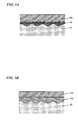
- FIG. 3A is a diagram schematically illustrating a coating structure in a case where a subsurface treatment layer (for example, a phosphate chemical conversion treatment coating or a porous metal plated coating formed by impact plating) 32 for roughening is first formed on the contact surface of a base body 30 that forms the pin 1 and/or the box 2 of the tubular threaded joint and a solid coating 31b, which contains the lubricating particles, is formed thereon.
- a subsurface treatment layer for example, a phosphate chemical conversion treatment coating or a porous metal plated coating formed by impact plating
- a solid coating 31b which contains the lubricating particles
- FIG. 3B is a diagram schematically illustrating a coating structure in a case where a solid coating 31a, which does not contain the lubricating particles, is formed as a first layer on the contact surface of a base body 30 of the pin 1 and/or the box 2 of the tubular threaded joint and a solid coating 31b, which contains the lubricating particles, is formed thereon as a second layer. It is preferable that, on the contact surface of the base body 30, the subsurface treatment coating for roughening be formed as illustrated in FIG. 3A , or the two layers of solid coatings be formed after roughening the contact surface itself.
- the contact surfaces of the other member (for example, the pin 1) that is not coated with the solid coating may be untreated.
- the above-described subsurface treatment for roughening may be performed thereon to roughen the contact surfaces. That is, the roughening can be performed by employing a blasting treatment, pickling, a chemical conversion treatment using phosphate, oxalate, borate, or the like, electro plating, composite plating in which a plated coating containing solid fine particles is formed, and a combination of two or more types thereof.
- a well-known waterproof coating such as a ultraviolet curable resin or a thermosetting resin may also be performed after the subsurface treatment, if desired.
- the surface treatment of the contact surfaces of the counterpart member is not particularly limited, the other surface treatments can also be performed.
- various solid coatings for example, a solid lubricating coating
- various solid coatings which are different from the solid coating of this embodiment can be formed on the contact surface of the counterpart member.
- the contact surface including the threaded portion and the unthreaded metal contact portion of the pin is referred to as a "pin surface” and the contact surface including the threaded portion and the unthreaded metal contact portion of the box is referred to as a "box surface”.
- Surface roughness is Rmax.
- “%” is “mass%” unless otherwise designated.
- the composition for solid coating formation was prepared by preparing a mixed solvent by mixing a dipolar aprotic solvent and pure water at a predetermined ratio, adding a powdery organic resin to the mixed solvent, and stirring the resultant at a temperature of 60 to 80°C using a stirrer to cause the resin powder to be dissolved or dispersed in the solvent.
- a mixed solvent by mixing a dipolar aprotic solvent and pure water at a predetermined ratio
- adding a powdery organic resin to the mixed solvent
- stirring the resultant at a temperature of 60 to 80°C using a stirrer to cause the resin powder to be dissolved or dispersed in the solvent.
- lubricating particles are added and further stirred to cause the particles to be uniformly dispersed for the preparation.
- the solvent is prepared to be the mixed solvent according to the embodiment of the present invention, and lubricating particles are further added and stirred depending on the case, thereby forming the composition for solid coating formation.
- Table 1 Symbol C Si Mn P S Cu Ni Cr Mo A 0.25 0.25 0.8 0.02 0.01 0.04 0.05 0.95 0.18 B 0.19 0.25 0.8 0.02 0.01 0.04 0.1 13 0.04 C 0.02 0.3 0.5 0.02 0.01 0.5 7 25 3.2 (Note) The content of each element is mass%, and the balance being Fe and impurities.
- the threaded joint was fastened at a fastening speed of 10 rpm and a fastening torque of 20 kN ⁇ m, and the seizure statuses of the pin surface and the box surface were examined after loosening.
- the first to fourth fastening and loosening operations were performed in a warm environment (about 20°C).
- the fifth and the rest fastening and loosening operations were performed at -20°C by cooling the periphery of the fastened part with dry ice. In a case where seizure marks generated by fastening were small and re-fastening was possible after repair, fastening and loosening were continued after the repair.
- the box surface was subjected to a mechanical grinding finish (a surface roughness of 3 ⁇ m) and thereafter was immersed in a manganese phosphate chemical conversion treatment liquid at 80°C to 95°C for 10 minutes, thereby forming a manganese phosphate coating (a surface roughness of 10 ⁇ m) having a thickness of 15 ⁇ m.
- the pin surface was subjected to a mechanical grinding finish (a surface roughness of 3 ⁇ m) and thereafter was immersed in a zinc phosphate chemical conversion treatment liquid at 75 to 85°C for 10 minutes, thereby forming a zinc phosphate coating (a surface roughness of 8 ⁇ m) having a thickness of 12 ⁇ m.
- a composition for solid coating formation made by mixing a polyamide-imide resin (TorlonTM 4000TF made by SOLVAY) as an organic resin that is soluble in a dipolar aprotic solvent, pure water, and NMP (N-methylpyrrolidone) as the dipolar aprotic solvent to have the composition of Example 1 of Table 2 was applied through spraying. Thereafter, resultant was subjected to predrying (at 80°C for 10 minutes) and main heating (at 230°C for 30 minutes), thereby forming a solid coating having an average thickness of 25 ⁇ m.
- the weather resistance test shown in Table 4 was performed. As shown in Table 5, deterioration such as peeling, discoloration, and hardness degradation of the solid coatings of the pin surface and the box surface was not confirmed after the test. Subsequently, the repeated fastening and loosening test was performed. After the ninth loosening, slight seizure had occurred in the threaded portion of the pin surface. However, the threaded portion was repaired and continuously subjected to the test as it was, and tenth fastening and loosening could be performed.
- the box surface was subjected to a mechanical grinding finish (a surface roughness of 3 ⁇ m) shown in Table 3 and thereafter was subjected to, first, Ni strike plating, and next, Cu plating through electro plating, thereby forming a plated coating (a surface roughness of 5 ⁇ m) having a total thickness of 10 ⁇ m.
- the pin surface was subjected to sandblasting in which sand is blasted 80 times to have a surface roughness of 10 ⁇ m.
- a composition for solid coating formation made by mixing a polyamide-imide resin (the same as that of Example 1) as an organic resin that is soluble in a dipolar aprotic solvent, pure water, DMSO (dimethylsulfoxide) as the dipolar aprotic solvent, and PTFE particles as lubricating particles at the ratio shown in Example 2 of Table 2 was applied through spraying. Thereafter, the resultant was subjected to predrying (at 85°C for 10 minutes) and main heating (at 280°C for 30 minutes), thereby forming a solid coating having an average thickness of 20 ⁇ m.
- the weather resistance test shown in Table 4 was performed. As shown in Table 5, deterioration such as peeling, discoloration, and hardness degradation of the solid coatings of the pin surface and the box surface was not confirmed after the test. Subsequently, the repeated fastening and loosening test was performed, and fastening and loosening could be performed 10 times without the occurrence of seizure.
- the box surface was subjected to a mechanical grinding finish (a surface roughness of 3 ⁇ m) and thereafter was subjected to, first, Ni strike plating, and next, Cu-Sn-Zn alloy plating through electro plating, thereby forming a plated coating (a surface roughness of 5 ⁇ m) having a total thickness of about 7 ⁇ m.
- the pin surface was subjected to sandblasting in which 80th sand is blasted to have a surface roughness of 10 ⁇ m.
- a composition for solid coating formation made by mixing a commercially available water-dispersible epoxy resin (MODEPICS301 (registered trademark) made by Arakawa Chemical Industries, Ltd., obtained in a water-dispersed liquid state) as an organic resin that is partially soluble at least in a dipolar aprotic solvent, GBL (y-butyrolactone) as the dipolar aprotic solvent, and amorphous graphite as lubricating particles at the ratio shown in Example 3 of Table 2 was applied through spraying. Thereafter, the resultant was subjected to predrying. (at 80°C for 10 minutes) and main heating (at 230°C for 30 minutes), thereby forming a solid coating having an average thickness of 20 ⁇ m.
- MODEPICS301 registered trademark
- GBL y-butyrolactone
- the weather resistance test shown in Table 4 was performed. As shown in Table 5, deterioration such as peeling, discoloration, and hardness degradation of the solid coatings of the pin surface and the box surface was not confirmed after the test. Subsequently, the fastening and loosening test was performed, and fastening and loosening could be performed 10 times without the occurrence of seizure.
- the pin surface and the box surface were subjected to a mechanical grinding finish (a surface roughness of 3 ⁇ m).
- POLYFLON registered trademark
- PTFE D-210C made by DAIKIN INDUSTRIES, ltd., obtained in a water-dispersed liquid state
- a composition for solid coating formation made by further adding and dispersing 17 parts by mass of amorphous graphite in 100 parts by mass of the composition for solid coating formation for the first layer was applied through spraying. Thereafter, the resultant was subjected to predrying (at 80°C for 10 minutes) and main heating (at 230°C for 30 minutes). Accordingly, a solid coating in which the first layer and the second layer have a total average thickness of 35 ⁇ m was formed. As shown in Table 3, the thickness of the first layer that did not contain lubricating particles was about 15 ⁇ m, and the thickness of the second layer that contained the lubricating particles (amorphous graphite) was about 20 ⁇ m.
- the weather resistance test shown in Table 4 was performed. As shown in Table 5, deterioration such as peeling, discoloration, and hardness degradation of the solid coatings of the pin surface and the box surface was not confirmed after the test. Subsequently, the repeated fastening and loosening test was performed. Fastening and loosening could be performed 10 times without the occurrence of seizure.
- the box surface was subjected to a mechanical grinding finish (a surface roughness of 3 ⁇ m) and thereafter was immersed in a manganese phosphate chemical conversion treatment liquid at 80 to 95°C for 10 minutes, thereby forming a manganese phosphate coating (a surface roughness of 10 ⁇ m) having a thickness of 15 ⁇ m.
- the compound grease was applied onto the surface subjected to the subsurface treatment, thereby forming a lubricating coating (a total amount of the compound grease applied onto the pin and the box was 50 g, and the application area thereof is approximately 1400 cm 2 in total)
- the pin surface was subjected to a mechanical grinding finish (a surface roughness of 3 ⁇ m) and thereafter was immersed in a zinc phosphate chemical conversion treatment liquid at 75 to 85°C for 10 minutes, thereby forming a zinc phosphate coating (a surface roughness of 8 ⁇ m) having a thickness of 12 ⁇ m.
- the compound grease as such was applied onto the surface thereof.
- the box surface was subjected to a mechanical grinding finish (a surface roughness of 3 ⁇ m) and thereafter was immersed in a manganese phosphate chemical conversion treatment liquid at 80 to 95°C for 10 minutes, thereby forming a manganese phosphate coating (a surface roughness of 10 ⁇ m) having a thickness of 15 ⁇ m.
- the pin surface was subjected to a mechanical grinding finish (a surface roughness of 3 ⁇ m) and thereafter was immersed in a zinc phosphate chemical conversion treatment liquid at 75 to 85°C for 10 minutes, thereby forming a zinc phosphate coating (a surface roughness of 8 ⁇ m) having a thickness of 12 ⁇ m.
- a composition for solid coating formation (corresponding to the composition described in Patent Document 1) made by mixing a polyamide-imide resin (VYLOMAX (registered trademark) HR-BNX made by TOYOBO CO., LTD.) that is soluble in a non-dipolar (non-polar) organic solvent, a mixed solvent including xylene and NMP at a mass ratio of 33 and 67 as an organic solvent, and molybdenum disulfide as lubricating particles at the ratio shown in Comparative Example 2 of Table 2 was applied through spraying. Thereafter, the resultant was subjected to predrying (at 80°C for 10 minutes) and main heating (at 230°C for 30 minutes), thereby forming a solid coating having an average thickness of 25 um.
- VYLOMAX registered trademark
- HR-BNX made by TOYOBO CO., LTD.
- the weather resistance test shown in Table 4 was performed. As shown in Table 5, partial peeling and blisters were observed from the solid coatings of the pin surface and the box surface after the test.
- seizure had started to occur in the threaded portion of the pin from the third fastening and loosening operation. Thereafter, the threaded portion was repaired to continue the test.
- the fifth fastening and loosening operation which was the fastening and loosening test performed at about -20°C, and seizure was at such a level that could not be repaired. Therefore, the test was stopped.
- the antirust properties of the tubular threaded joints of Examples 1 to 4 and Comparative Examples 1 and 2 were examined by performing the same subsurface treatments as those of the pin surfaces and the box surfaces of Table 3 on additionally prepared coupon specimens (70 mm ⁇ 150 mm ⁇ 1.0 mm thick) and forming the same solid coatings.
- the specimens were provided for a salt spray test (based on JIS Z2371 (corresponding to ISO 9227), a temperature of 35°C, 1000 hours) and a humidity test (based on JIS K5600-7-2 (corresponding to ISO 6270), a temperature of 50°C, a humidity of 98%, 200 hours) to examine presence or absence of rust being generated. As a result, it was confirmed that there was no rust being generated in all the Examples 1 to 4.
Landscapes
- Chemical & Material Sciences (AREA)
- Engineering & Computer Science (AREA)
- Organic Chemistry (AREA)
- General Engineering & Computer Science (AREA)
- Chemical Kinetics & Catalysis (AREA)
- Life Sciences & Earth Sciences (AREA)
- Wood Science & Technology (AREA)
- Materials Engineering (AREA)
- Mechanical Engineering (AREA)
- Medicinal Chemistry (AREA)
- Polymers & Plastics (AREA)
- Health & Medical Sciences (AREA)
- General Chemical & Material Sciences (AREA)
- Oil, Petroleum & Natural Gas (AREA)
- Non-Disconnectible Joints And Screw-Threaded Joints (AREA)
- Paints Or Removers (AREA)
- Mining & Mineral Resources (AREA)
- Geology (AREA)
- Fluid Mechanics (AREA)
- General Life Sciences & Earth Sciences (AREA)
- Geochemistry & Mineralogy (AREA)
- Environmental & Geological Engineering (AREA)
- Physics & Mathematics (AREA)
- Lubricants (AREA)
Priority Applications (1)
| Application Number | Priority Date | Filing Date | Title |
|---|---|---|---|
| PL13836965T PL2896683T3 (pl) | 2012-09-12 | 2013-09-10 | Kompozycja do wytwarzania powłoki stałej i gwintowane złącze rurowe |
Applications Claiming Priority (2)
| Application Number | Priority Date | Filing Date | Title |
|---|---|---|---|
| JP2012200118 | 2012-09-12 | ||
| PCT/JP2013/074356 WO2014042144A1 (ja) | 2012-09-12 | 2013-09-10 | 固体被膜形成用組成物及び管状ねじ継手 |
Publications (3)
| Publication Number | Publication Date |
|---|---|
| EP2896683A1 true EP2896683A1 (de) | 2015-07-22 |
| EP2896683A4 EP2896683A4 (de) | 2016-05-25 |
| EP2896683B1 EP2896683B1 (de) | 2018-04-18 |
Family
ID=50278255
Family Applications (1)
| Application Number | Title | Priority Date | Filing Date |
|---|---|---|---|
| EP13836965.7A Not-in-force EP2896683B1 (de) | 2012-09-12 | 2013-09-10 | Zusammensetzung zur herstellung einer festen beschichtung und rohrförmige schraubverbindung |
Country Status (15)
| Country | Link |
|---|---|
| US (2) | US10150887B2 (de) |
| EP (1) | EP2896683B1 (de) |
| JP (1) | JP5984945B2 (de) |
| CN (1) | CN104619819B (de) |
| AR (1) | AR092497A1 (de) |
| AU (1) | AU2013316601B2 (de) |
| BR (1) | BR112015004871A2 (de) |
| CA (1) | CA2884236C (de) |
| EA (1) | EA029511B1 (de) |
| IN (1) | IN2015DN01475A (de) |
| MX (1) | MX366221B (de) |
| MY (1) | MY169937A (de) |
| PL (1) | PL2896683T3 (de) |
| UA (1) | UA113996C2 (de) |
| WO (1) | WO2014042144A1 (de) |
Families Citing this family (15)
| Publication number | Priority date | Publication date | Assignee | Title |
|---|---|---|---|---|
| UA113996C2 (xx) * | 2012-09-12 | 2017-04-10 | Композиція для утворення твердого покриття і трубне нарізне з'єднання | |
| WO2015174292A1 (ja) * | 2014-05-16 | 2015-11-19 | Nokクリューバー株式会社 | 塗膜付摺動部材及び塗膜形成方法 |
| AT516684B1 (de) * | 2015-01-13 | 2018-08-15 | Voestalpine Tubulars Gmbh & Co Kg | Lösbare Gewindeverbindung mit asymmetrischer Beschichtung |
| JP6735015B2 (ja) * | 2015-12-16 | 2020-08-05 | 株式会社スリーボンド | 塗膜形成樹脂組成物 |
| JP6764683B2 (ja) * | 2016-05-13 | 2020-10-07 | Jfeコンテイナー株式会社 | ドラム缶用口金及び鋼製ドラム缶 |
| JP6794023B2 (ja) * | 2016-08-04 | 2020-12-02 | 株式会社青山製作所 | ねじ部品用防錆処理液、防錆処理されたねじ部品の製造方法及び防錆処理されたねじ部品 |
| KR102133142B1 (ko) * | 2016-12-23 | 2020-07-10 | 산드빅 인터렉츄얼 프로퍼티 에이비 | 복합 튜브를 제조하기 위한 방법 |
| PL3633253T3 (pl) | 2017-05-22 | 2023-12-11 | Nippon Steel Corporation | Połączenie gwintowe dla rur lub przewodów rurowych oraz sposób wykonywania połączenia gwintowego dla rur lub przewodów rurowych |
| JP6815498B2 (ja) * | 2017-05-22 | 2021-01-20 | 日本製鉄株式会社 | 管用ねじ継手及び管用ねじ継手の製造方法 |
| WO2019075019A1 (en) * | 2017-10-10 | 2019-04-18 | Cameron International Corporation | PIPE COATING IN SOLID STATE |
| JP2020186361A (ja) * | 2019-05-09 | 2020-11-19 | 株式会社フコク | 金属部材用コーティング膜 |
| MX2022009896A (es) * | 2020-02-19 | 2022-08-25 | Nippon Steel Corp | Conexion roscada para tubos y metodo para producir una conexion roscada para tubos. |
| MX2023001972A (es) | 2020-08-20 | 2023-02-23 | Nippon Steel Corp | Tubo de metal para pozos de petroleo y metodo para producir tuberia metalica para pozos de petroleo. |
| JP7470198B2 (ja) * | 2021-05-31 | 2024-04-17 | Jfeスチール株式会社 | 固体潤滑被膜形成用の薬剤、油井管、及び油井管ねじ継手 |
| CN117425719A (zh) * | 2021-05-31 | 2024-01-19 | 杰富意钢铁株式会社 | 固体润滑被膜形成用试剂、油井管和油井管螺纹接头 |
Citations (5)
| Publication number | Priority date | Publication date | Assignee | Title |
|---|---|---|---|---|
| US20030159764A1 (en) * | 2001-04-11 | 2003-08-28 | Kunio Goto | Threaded joint for steel pipes and process for the surface treatment thereof |
| US7208227B2 (en) * | 2002-02-12 | 2007-04-24 | Daikin Industries, Ltd. | ETFE lining member |
| US20080129044A1 (en) * | 2006-12-01 | 2008-06-05 | Gabriel Eduardo Carcagno | Nanocomposite coatings for threaded connections |
| US20110041924A1 (en) * | 2004-11-24 | 2011-02-24 | E. I. Du Pont De Nemours And Company | System of Pipes for Use in Oil Wells |
| EP2302273A1 (de) * | 2005-03-29 | 2011-03-30 | Sumitomo Metal Industries, Ltd. | Schraubverbindung für Stahlrohre |
Family Cites Families (20)
| Publication number | Priority date | Publication date | Assignee | Title |
|---|---|---|---|---|
| US4741939A (en) * | 1985-10-23 | 1988-05-03 | Westinghouse Electric Corp. | Compatible self-crosslinking poly (amide-imide) polyepoxide resin blends and laminates made therewith |
| JP2811784B2 (ja) * | 1988-09-09 | 1998-10-15 | 三菱化学株式会社 | 樹脂組成物 |
| US5087658A (en) * | 1988-12-29 | 1992-02-11 | Hitachi Chemical Company, Ltd. | Heat-resistant resin paste and integrated circuit device produced by using the heat-resistant resin paste |
| US5137310A (en) | 1990-11-27 | 1992-08-11 | Vallourec Industries | Assembly arrangement using frustoconical screwthreads for tubes |
| WO1996010710A1 (fr) | 1994-10-04 | 1996-04-11 | Nippon Steel Corporation | Union de tuyaux d'acier presentant une resistance elevee au grippage et traitement de surface destine a cet effet |
| FR2813375B1 (fr) * | 2000-08-31 | 2003-06-20 | Vallourec Mannesmann Oil & Gas | Element filete pour joint filete tubulaire resistant au grippage |
| JP4680446B2 (ja) | 2001-08-31 | 2011-05-11 | Jfeスチール株式会社 | 油井鋼管用継手 |
| ITRM20020512A1 (it) * | 2002-10-10 | 2004-04-11 | Tenaris Connections Bv | Tubo filettato con trattamento superficiale. |
| JP4534916B2 (ja) * | 2005-09-01 | 2010-09-01 | ダイキン工業株式会社 | 含フッ素重合体水性組成物及び被膜物品 |
| AR057940A1 (es) * | 2005-11-30 | 2007-12-26 | Tenaris Connections Ag | Conexiones roscadas con recubrimientos de alta y baja friccion |
| JP4941058B2 (ja) | 2007-04-02 | 2012-05-30 | 住友金属工業株式会社 | 鋼管用ねじ継手 |
| JP5266711B2 (ja) * | 2007-05-23 | 2013-08-21 | ダイキン工業株式会社 | フッ素樹脂塗料組成物及び塗装物品 |
| WO2009014009A1 (ja) * | 2007-07-24 | 2009-01-29 | Daikin Industries, Ltd. | 被覆用組成物 |
| US8597780B2 (en) * | 2007-08-10 | 2013-12-03 | Dai Nippon Printing Co., Ltd. | Hard coat film |
| MY161993A (en) | 2007-12-04 | 2017-05-31 | Sumitomo Metal Ind | Threaded joint for pipes |
| EP2287236B1 (de) * | 2008-05-21 | 2017-07-26 | Toray Industries, Inc. | Verfahren zur herstellung von feinen polymerpartikeln |
| WO2011062006A1 (ja) * | 2009-11-19 | 2011-05-26 | 東レ株式会社 | ポリアミドイミド樹脂微粒子の製造方法、ポリアミドイミド樹脂微粒子 |
| MX2012014132A (es) * | 2010-06-07 | 2013-02-11 | Syngenta Participations Ag | Composicion quimica estabilizada. |
| JP5722752B2 (ja) * | 2011-11-18 | 2015-05-27 | 新日鐵住金株式会社 | 高トルク締結性能に優れた管状ねじ継手 |
| UA113996C2 (xx) * | 2012-09-12 | 2017-04-10 | Композиція для утворення твердого покриття і трубне нарізне з'єднання |
-
2013
- 2013-09-10 UA UAA201502206A patent/UA113996C2/uk unknown
- 2013-09-10 JP JP2014535546A patent/JP5984945B2/ja active Active
- 2013-09-10 MY MYPI2015700640A patent/MY169937A/en unknown
- 2013-09-10 AR ARP130103211A patent/AR092497A1/es active IP Right Grant
- 2013-09-10 AU AU2013316601A patent/AU2013316601B2/en not_active Ceased
- 2013-09-10 CA CA2884236A patent/CA2884236C/en not_active Expired - Fee Related
- 2013-09-10 EA EA201590378A patent/EA029511B1/ru not_active IP Right Cessation
- 2013-09-10 PL PL13836965T patent/PL2896683T3/pl unknown
- 2013-09-10 CN CN201380046990.6A patent/CN104619819B/zh not_active Expired - Fee Related
- 2013-09-10 MX MX2015003058A patent/MX366221B/es active IP Right Grant
- 2013-09-10 EP EP13836965.7A patent/EP2896683B1/de not_active Not-in-force
- 2013-09-10 WO PCT/JP2013/074356 patent/WO2014042144A1/ja active Application Filing
- 2013-09-10 BR BR112015004871A patent/BR112015004871A2/pt active Search and Examination
- 2013-09-10 US US14/426,924 patent/US10150887B2/en not_active Expired - Fee Related
- 2013-09-10 IN IN1475DEN2015 patent/IN2015DN01475A/en unknown
-
2018
- 2018-07-19 US US16/039,682 patent/US10494545B2/en not_active Expired - Fee Related
Patent Citations (5)
| Publication number | Priority date | Publication date | Assignee | Title |
|---|---|---|---|---|
| US20030159764A1 (en) * | 2001-04-11 | 2003-08-28 | Kunio Goto | Threaded joint for steel pipes and process for the surface treatment thereof |
| US7208227B2 (en) * | 2002-02-12 | 2007-04-24 | Daikin Industries, Ltd. | ETFE lining member |
| US20110041924A1 (en) * | 2004-11-24 | 2011-02-24 | E. I. Du Pont De Nemours And Company | System of Pipes for Use in Oil Wells |
| EP2302273A1 (de) * | 2005-03-29 | 2011-03-30 | Sumitomo Metal Industries, Ltd. | Schraubverbindung für Stahlrohre |
| US20080129044A1 (en) * | 2006-12-01 | 2008-06-05 | Gabriel Eduardo Carcagno | Nanocomposite coatings for threaded connections |
Non-Patent Citations (2)
| Title |
|---|
| None * |
| See also references of WO2014042144A1 * |
Also Published As
| Publication number | Publication date |
|---|---|
| JPWO2014042144A1 (ja) | 2016-08-18 |
| EA201590378A1 (ru) | 2015-06-30 |
| CA2884236A1 (en) | 2014-03-20 |
| AU2013316601A1 (en) | 2015-03-26 |
| MX2015003058A (es) | 2015-07-14 |
| WO2014042144A1 (ja) | 2014-03-20 |
| CA2884236C (en) | 2017-05-30 |
| BR112015004871A2 (pt) | 2017-07-04 |
| US10150887B2 (en) | 2018-12-11 |
| AR092497A1 (es) | 2015-04-22 |
| CN104619819B (zh) | 2017-03-22 |
| US20150210888A1 (en) | 2015-07-30 |
| IN2015DN01475A (de) | 2015-07-03 |
| US20180327633A1 (en) | 2018-11-15 |
| JP5984945B2 (ja) | 2016-09-06 |
| EA029511B1 (ru) | 2018-04-30 |
| EP2896683B1 (de) | 2018-04-18 |
| PL2896683T3 (pl) | 2018-11-30 |
| MY169937A (en) | 2019-06-18 |
| CN104619819A (zh) | 2015-05-13 |
| AU2013316601B2 (en) | 2017-03-30 |
| US10494545B2 (en) | 2019-12-03 |
| UA113996C2 (xx) | 2017-04-10 |
| MX366221B (es) | 2019-07-03 |
| EP2896683A4 (de) | 2016-05-25 |
Similar Documents
| Publication | Publication Date | Title |
|---|---|---|
| US10494545B2 (en) | Composition for solid coating formation and tubular threaded joint | |
| JP6893978B2 (ja) | 管用ねじ継手及び管用ねじ継手の製造方法 | |
| US7866706B2 (en) | Threaded joint for steel pipe | |
| JP4687715B2 (ja) | 鋼管用ねじ継手 | |
| EP2881454B1 (de) | Röhrenförmige gewindeverbindung und schmierbeschichtungsbildende zusammensetzung zur verwendung darin | |
| CN106103676B (zh) | 固体润滑皮膜用组合物、具备由该组合物形成的固体润滑皮膜的管用螺纹接头、以及该管用螺纹接头的制造方法 | |
| US11391400B2 (en) | Threaded connection for pipes or tubes and method for producing the threaded connection for pipes or tubes | |
| US20230349503A1 (en) | Oil-well metal pipe | |
| OA17282A (en) | Composition for use in forming solid coating film, and tubular threaded joint. | |
| OA18009A (en) | Solid lubricant coating composition, threaded joint for pipes comprising solid lubricant coating formed using said composition, and production method for said threaded joint for pipes. |
Legal Events
| Date | Code | Title | Description |
|---|---|---|---|
| PUAI | Public reference made under article 153(3) epc to a published international application that has entered the european phase |
Free format text: ORIGINAL CODE: 0009012 |
|
| 17P | Request for examination filed |
Effective date: 20150402 |
|
| AK | Designated contracting states |
Kind code of ref document: A1 Designated state(s): AL AT BE BG CH CY CZ DE DK EE ES FI FR GB GR HR HU IE IS IT LI LT LU LV MC MK MT NL NO PL PT RO RS SE SI SK SM TR |
|
| AX | Request for extension of the european patent |
Extension state: BA ME |
|
| DAX | Request for extension of the european patent (deleted) | ||
| RA4 | Supplementary search report drawn up and despatched (corrected) |
Effective date: 20160428 |
|
| RIC1 | Information provided on ipc code assigned before grant |
Ipc: C10M 145/20 20060101ALI20160421BHEP Ipc: C10N 30/00 20060101ALI20160421BHEP Ipc: C10M 149/18 20060101ALI20160421BHEP Ipc: C09D 7/12 20060101ALI20160421BHEP Ipc: C09D 179/08 20060101ALI20160421BHEP Ipc: F16L 58/18 20060101ALI20160421BHEP Ipc: C10N 30/12 20060101ALI20160421BHEP Ipc: C10M 147/00 20060101ALI20160421BHEP Ipc: C09D 127/18 20060101ALI20160421BHEP Ipc: F16L 15/04 20060101ALI20160421BHEP Ipc: C08K 5/41 20060101ALI20160421BHEP Ipc: C09D 163/00 20060101ALI20160421BHEP Ipc: C10N 40/00 20060101ALI20160421BHEP Ipc: F16L 15/00 20060101ALI20160421BHEP Ipc: C09D 201/04 20060101ALI20160421BHEP Ipc: C09D 179/02 20060101ALI20160421BHEP Ipc: C08G 73/02 20060101ALI20160421BHEP Ipc: C10M 173/02 20060101AFI20160421BHEP Ipc: C09D 201/00 20060101ALI20160421BHEP Ipc: C08K 3/04 20060101ALI20160421BHEP |
|
| RIN1 | Information on inventor provided before grant (corrected) |
Inventor name: GOTO KUNIO |
|
| GRAP | Despatch of communication of intention to grant a patent |
Free format text: ORIGINAL CODE: EPIDOSNIGR1 |
|
| INTG | Intention to grant announced |
Effective date: 20170616 |
|
| RAP1 | Party data changed (applicant data changed or rights of an application transferred) |
Owner name: VALLOUREC OIL AND GAS FRANCE Owner name: NIPPON STEEL & SUMITOMO METAL CORPORATION |
|
| GRAS | Grant fee paid |
Free format text: ORIGINAL CODE: EPIDOSNIGR3 |
|
| GRAJ | Information related to disapproval of communication of intention to grant by the applicant or resumption of examination proceedings by the epo deleted |
Free format text: ORIGINAL CODE: EPIDOSDIGR1 |
|
| GRAL | Information related to payment of fee for publishing/printing deleted |
Free format text: ORIGINAL CODE: EPIDOSDIGR3 |
|
| INTC | Intention to grant announced (deleted) | ||
| GRAP | Despatch of communication of intention to grant a patent |
Free format text: ORIGINAL CODE: EPIDOSNIGR1 |
|
| RIC1 | Information provided on ipc code assigned before grant |
Ipc: C09D 7/40 20180101ALI20180118BHEP Ipc: C10M 147/00 20060101ALI20180118BHEP Ipc: C09D 163/00 20060101ALI20180118BHEP Ipc: C09D 127/18 20060101ALI20180118BHEP Ipc: C09D 179/08 20060101ALI20180118BHEP Ipc: C10N 30/12 20060101ALI20180118BHEP Ipc: C10M 145/20 20060101ALI20180118BHEP Ipc: C10M 149/18 20060101ALI20180118BHEP Ipc: C08K 5/41 20060101ALI20180118BHEP Ipc: F16L 15/04 20060101ALI20180118BHEP Ipc: C09D 179/02 20060101ALI20180118BHEP Ipc: C10N 30/00 20060101ALI20180118BHEP Ipc: C08G 73/02 20060101ALI20180118BHEP Ipc: F16L 58/18 20060101ALI20180118BHEP Ipc: C10M 173/02 20060101AFI20180118BHEP Ipc: F16L 15/00 20060101ALI20180118BHEP Ipc: C08K 3/04 20060101ALI20180118BHEP Ipc: C09D 201/04 20060101ALI20180118BHEP Ipc: C10N 40/00 20060101ALI20180118BHEP Ipc: C09D 201/00 20060101ALI20180118BHEP |
|
| INTG | Intention to grant announced |
Effective date: 20180216 |
|
| GRAA | (expected) grant |
Free format text: ORIGINAL CODE: 0009210 |
|
| AK | Designated contracting states |
Kind code of ref document: B1 Designated state(s): AL AT BE BG CH CY CZ DE DK EE ES FI FR GB GR HR HU IE IS IT LI LT LU LV MC MK MT NL NO PL PT RO RS SE SI SK SM TR |
|
| REG | Reference to a national code |
Ref country code: GB Ref legal event code: FG4D |
|
| REG | Reference to a national code |
Ref country code: CH Ref legal event code: EP |
|
| REG | Reference to a national code |
Ref country code: DE Ref legal event code: R096 Ref document number: 602013036228 Country of ref document: DE |
|
| REG | Reference to a national code |
Ref country code: AT Ref legal event code: REF Ref document number: 990472 Country of ref document: AT Kind code of ref document: T Effective date: 20180515 |
|
| REG | Reference to a national code |
Ref country code: IE Ref legal event code: FG4D |
|
| REG | Reference to a national code |
Ref country code: RO Ref legal event code: EPE |
|
| REG | Reference to a national code |
Ref country code: NL Ref legal event code: FP |
|
| REG | Reference to a national code |
Ref country code: NO Ref legal event code: T2 Effective date: 20180418 |
|
| REG | Reference to a national code |
Ref country code: LT Ref legal event code: MG4D |
|
| REG | Reference to a national code |
Ref country code: FR Ref legal event code: PLFP Year of fee payment: 6 |
|
| PG25 | Lapsed in a contracting state [announced via postgrant information from national office to epo] |
Ref country code: ES Free format text: LAPSE BECAUSE OF FAILURE TO SUBMIT A TRANSLATION OF THE DESCRIPTION OR TO PAY THE FEE WITHIN THE PRESCRIBED TIME-LIMIT Effective date: 20180418 Ref country code: LT Free format text: LAPSE BECAUSE OF FAILURE TO SUBMIT A TRANSLATION OF THE DESCRIPTION OR TO PAY THE FEE WITHIN THE PRESCRIBED TIME-LIMIT Effective date: 20180418 Ref country code: FI Free format text: LAPSE BECAUSE OF FAILURE TO SUBMIT A TRANSLATION OF THE DESCRIPTION OR TO PAY THE FEE WITHIN THE PRESCRIBED TIME-LIMIT Effective date: 20180418 Ref country code: BG Free format text: LAPSE BECAUSE OF FAILURE TO SUBMIT A TRANSLATION OF THE DESCRIPTION OR TO PAY THE FEE WITHIN THE PRESCRIBED TIME-LIMIT Effective date: 20180718 Ref country code: SE Free format text: LAPSE BECAUSE OF FAILURE TO SUBMIT A TRANSLATION OF THE DESCRIPTION OR TO PAY THE FEE WITHIN THE PRESCRIBED TIME-LIMIT Effective date: 20180418 Ref country code: AL Free format text: LAPSE BECAUSE OF FAILURE TO SUBMIT A TRANSLATION OF THE DESCRIPTION OR TO PAY THE FEE WITHIN THE PRESCRIBED TIME-LIMIT Effective date: 20180418 |
|
| PG25 | Lapsed in a contracting state [announced via postgrant information from national office to epo] |
Ref country code: GR Free format text: LAPSE BECAUSE OF FAILURE TO SUBMIT A TRANSLATION OF THE DESCRIPTION OR TO PAY THE FEE WITHIN THE PRESCRIBED TIME-LIMIT Effective date: 20180719 Ref country code: RS Free format text: LAPSE BECAUSE OF FAILURE TO SUBMIT A TRANSLATION OF THE DESCRIPTION OR TO PAY THE FEE WITHIN THE PRESCRIBED TIME-LIMIT Effective date: 20180418 Ref country code: LV Free format text: LAPSE BECAUSE OF FAILURE TO SUBMIT A TRANSLATION OF THE DESCRIPTION OR TO PAY THE FEE WITHIN THE PRESCRIBED TIME-LIMIT Effective date: 20180418 Ref country code: HR Free format text: LAPSE BECAUSE OF FAILURE TO SUBMIT A TRANSLATION OF THE DESCRIPTION OR TO PAY THE FEE WITHIN THE PRESCRIBED TIME-LIMIT Effective date: 20180418 |
|
| PG25 | Lapsed in a contracting state [announced via postgrant information from national office to epo] |
Ref country code: PT Free format text: LAPSE BECAUSE OF FAILURE TO SUBMIT A TRANSLATION OF THE DESCRIPTION OR TO PAY THE FEE WITHIN THE PRESCRIBED TIME-LIMIT Effective date: 20180820 |
|
| REG | Reference to a national code |
Ref country code: DE Ref legal event code: R097 Ref document number: 602013036228 Country of ref document: DE |
|
| PG25 | Lapsed in a contracting state [announced via postgrant information from national office to epo] |
Ref country code: SK Free format text: LAPSE BECAUSE OF FAILURE TO SUBMIT A TRANSLATION OF THE DESCRIPTION OR TO PAY THE FEE WITHIN THE PRESCRIBED TIME-LIMIT Effective date: 20180418 Ref country code: DK Free format text: LAPSE BECAUSE OF FAILURE TO SUBMIT A TRANSLATION OF THE DESCRIPTION OR TO PAY THE FEE WITHIN THE PRESCRIBED TIME-LIMIT Effective date: 20180418 Ref country code: EE Free format text: LAPSE BECAUSE OF FAILURE TO SUBMIT A TRANSLATION OF THE DESCRIPTION OR TO PAY THE FEE WITHIN THE PRESCRIBED TIME-LIMIT Effective date: 20180418 |
|
| REG | Reference to a national code |
Ref country code: CH Ref legal event code: PK Free format text: BERICHTIGUNGEN |
|
| RIC2 | Information provided on ipc code assigned after grant |
Ipc: C09D 201/00 20060101ALI20180118BHEP Ipc: F16L 15/00 20060101ALI20180118BHEP Ipc: C10M 147/00 20060101ALI20180118BHEP Ipc: C10M 173/02 20060101AFI20180118BHEP Ipc: C10M 145/20 20060101ALI20180118BHEP Ipc: C09D 179/02 20060101ALI20180118BHEP Ipc: C10M 149/18 20060101ALI20180118BHEP Ipc: C09D 163/00 20060101ALI20180118BHEP Ipc: C09D 201/04 20060101ALI20180118BHEP Ipc: C08G 73/02 20060101ALI20180118BHEP Ipc: C09D 7/40 20180101ALI20180118BHEP Ipc: F16L 58/18 20060101ALI20180118BHEP Ipc: C09D 127/18 20060101ALI20180118BHEP Ipc: F16L 15/04 20060101ALI20180118BHEP Ipc: C08K 3/04 20060101ALI20180118BHEP Ipc: C10N 40/00 20060101ALI20180118BHEP Ipc: C10N 30/00 20060101ALI20180118BHEP Ipc: C08K 5/41 20060101ALI20180118BHEP Ipc: C10N 30/12 20060101ALI20180118BHEP Ipc: C09D 179/08 20060101ALI20180118BHEP |
|
| PLBE | No opposition filed within time limit |
Free format text: ORIGINAL CODE: 0009261 |
|
| STAA | Information on the status of an ep patent application or granted ep patent |
Free format text: STATUS: NO OPPOSITION FILED WITHIN TIME LIMIT |
|
| PG25 | Lapsed in a contracting state [announced via postgrant information from national office to epo] |
Ref country code: SM Free format text: LAPSE BECAUSE OF FAILURE TO SUBMIT A TRANSLATION OF THE DESCRIPTION OR TO PAY THE FEE WITHIN THE PRESCRIBED TIME-LIMIT Effective date: 20180418 |
|
| 26N | No opposition filed |
Effective date: 20190121 |
|
| PG25 | Lapsed in a contracting state [announced via postgrant information from national office to epo] |
Ref country code: MC Free format text: LAPSE BECAUSE OF FAILURE TO SUBMIT A TRANSLATION OF THE DESCRIPTION OR TO PAY THE FEE WITHIN THE PRESCRIBED TIME-LIMIT Effective date: 20180418 |
|
| REG | Reference to a national code |
Ref country code: CH Ref legal event code: PL |
|
| PG25 | Lapsed in a contracting state [announced via postgrant information from national office to epo] |
Ref country code: SI Free format text: LAPSE BECAUSE OF FAILURE TO SUBMIT A TRANSLATION OF THE DESCRIPTION OR TO PAY THE FEE WITHIN THE PRESCRIBED TIME-LIMIT Effective date: 20180418 |
|
| REG | Reference to a national code |
Ref country code: DE Ref legal event code: R082 Ref document number: 602013036228 Country of ref document: DE Representative=s name: VOSSIUS & PARTNER PATENTANWAELTE RECHTSANWAELT, DE Ref country code: DE Ref legal event code: R081 Ref document number: 602013036228 Country of ref document: DE Owner name: VALLOUREC OIL AND GAS FRANCE, FR Free format text: FORMER OWNERS: NIPPON STEEL & SUMITOMO METAL CORPORATION, TOKIO/TOKYO, JP; VALLOUREC OIL AND GAS FRANCE, AULNOYE-AYMERIES, FR Ref country code: DE Ref legal event code: R081 Ref document number: 602013036228 Country of ref document: DE Owner name: NIPPON STEEL CORPORATION, JP Free format text: FORMER OWNERS: NIPPON STEEL & SUMITOMO METAL CORPORATION, TOKIO/TOKYO, JP; VALLOUREC OIL AND GAS FRANCE, AULNOYE-AYMERIES, FR |
|
| REG | Reference to a national code |
Ref country code: BE Ref legal event code: MM Effective date: 20180930 |
|
| REG | Reference to a national code |
Ref country code: IE Ref legal event code: MM4A |
|
| PG25 | Lapsed in a contracting state [announced via postgrant information from national office to epo] |
Ref country code: LU Free format text: LAPSE BECAUSE OF NON-PAYMENT OF DUE FEES Effective date: 20180910 |
|
| PG25 | Lapsed in a contracting state [announced via postgrant information from national office to epo] |
Ref country code: IE Free format text: LAPSE BECAUSE OF NON-PAYMENT OF DUE FEES Effective date: 20180910 |
|
| PG25 | Lapsed in a contracting state [announced via postgrant information from national office to epo] |
Ref country code: CH Free format text: LAPSE BECAUSE OF NON-PAYMENT OF DUE FEES Effective date: 20180930 Ref country code: BE Free format text: LAPSE BECAUSE OF NON-PAYMENT OF DUE FEES Effective date: 20180930 Ref country code: LI Free format text: LAPSE BECAUSE OF NON-PAYMENT OF DUE FEES Effective date: 20180930 |
|
| PG25 | Lapsed in a contracting state [announced via postgrant information from national office to epo] |
Ref country code: MT Free format text: LAPSE BECAUSE OF NON-PAYMENT OF DUE FEES Effective date: 20180910 |
|
| REG | Reference to a national code |
Ref country code: AT Ref legal event code: UEP Ref document number: 990472 Country of ref document: AT Kind code of ref document: T Effective date: 20180418 |
|
| PG25 | Lapsed in a contracting state [announced via postgrant information from national office to epo] |
Ref country code: TR Free format text: LAPSE BECAUSE OF FAILURE TO SUBMIT A TRANSLATION OF THE DESCRIPTION OR TO PAY THE FEE WITHIN THE PRESCRIBED TIME-LIMIT Effective date: 20180418 |
|
| PG25 | Lapsed in a contracting state [announced via postgrant information from national office to epo] |
Ref country code: HU Free format text: LAPSE BECAUSE OF FAILURE TO SUBMIT A TRANSLATION OF THE DESCRIPTION OR TO PAY THE FEE WITHIN THE PRESCRIBED TIME-LIMIT; INVALID AB INITIO Effective date: 20130910 Ref country code: CY Free format text: LAPSE BECAUSE OF FAILURE TO SUBMIT A TRANSLATION OF THE DESCRIPTION OR TO PAY THE FEE WITHIN THE PRESCRIBED TIME-LIMIT Effective date: 20180418 Ref country code: MK Free format text: LAPSE BECAUSE OF NON-PAYMENT OF DUE FEES Effective date: 20180418 |
|
| PG25 | Lapsed in a contracting state [announced via postgrant information from national office to epo] |
Ref country code: IS Free format text: LAPSE BECAUSE OF FAILURE TO SUBMIT A TRANSLATION OF THE DESCRIPTION OR TO PAY THE FEE WITHIN THE PRESCRIBED TIME-LIMIT Effective date: 20180818 |
|
| PGFP | Annual fee paid to national office [announced via postgrant information from national office to epo] |
Ref country code: NL Payment date: 20200814 Year of fee payment: 8 |
|
| PGFP | Annual fee paid to national office [announced via postgrant information from national office to epo] |
Ref country code: DE Payment date: 20200826 Year of fee payment: 8 Ref country code: GB Payment date: 20200902 Year of fee payment: 8 Ref country code: FR Payment date: 20200812 Year of fee payment: 8 Ref country code: CZ Payment date: 20200831 Year of fee payment: 8 Ref country code: NO Payment date: 20200910 Year of fee payment: 8 Ref country code: RO Payment date: 20200819 Year of fee payment: 8 |
|
| PGFP | Annual fee paid to national office [announced via postgrant information from national office to epo] |
Ref country code: IT Payment date: 20200812 Year of fee payment: 8 Ref country code: AT Payment date: 20200825 Year of fee payment: 8 Ref country code: PL Payment date: 20200728 Year of fee payment: 8 |
|
| REG | Reference to a national code |
Ref country code: DE Ref legal event code: R119 Ref document number: 602013036228 Country of ref document: DE |
|
| REG | Reference to a national code |
Ref country code: NO Ref legal event code: MMEP |
|
| REG | Reference to a national code |
Ref country code: NL Ref legal event code: MM Effective date: 20211001 |
|
| REG | Reference to a national code |
Ref country code: AT Ref legal event code: MM01 Ref document number: 990472 Country of ref document: AT Kind code of ref document: T Effective date: 20210910 |
|
| GBPC | Gb: european patent ceased through non-payment of renewal fee |
Effective date: 20210910 |
|
| PG25 | Lapsed in a contracting state [announced via postgrant information from national office to epo] |
Ref country code: RO Free format text: LAPSE BECAUSE OF NON-PAYMENT OF DUE FEES Effective date: 20210910 Ref country code: CZ Free format text: LAPSE BECAUSE OF NON-PAYMENT OF DUE FEES Effective date: 20210910 |
|
| PG25 | Lapsed in a contracting state [announced via postgrant information from national office to epo] |
Ref country code: NL Free format text: LAPSE BECAUSE OF NON-PAYMENT OF DUE FEES Effective date: 20211001 |
|
| PG25 | Lapsed in a contracting state [announced via postgrant information from national office to epo] |
Ref country code: NO Free format text: LAPSE BECAUSE OF NON-PAYMENT OF DUE FEES Effective date: 20210930 Ref country code: GB Free format text: LAPSE BECAUSE OF NON-PAYMENT OF DUE FEES Effective date: 20210910 Ref country code: FR Free format text: LAPSE BECAUSE OF NON-PAYMENT OF DUE FEES Effective date: 20210930 Ref country code: DE Free format text: LAPSE BECAUSE OF NON-PAYMENT OF DUE FEES Effective date: 20220401 |
|
| PG25 | Lapsed in a contracting state [announced via postgrant information from national office to epo] |
Ref country code: AT Free format text: LAPSE BECAUSE OF NON-PAYMENT OF DUE FEES Effective date: 20210910 |
|
| PG25 | Lapsed in a contracting state [announced via postgrant information from national office to epo] |
Ref country code: IT Free format text: LAPSE BECAUSE OF NON-PAYMENT OF DUE FEES Effective date: 20210910 |
|
| PG25 | Lapsed in a contracting state [announced via postgrant information from national office to epo] |
Ref country code: PL Free format text: LAPSE BECAUSE OF NON-PAYMENT OF DUE FEES Effective date: 20210910 |