EP2882340B1 - Filtering blood - Google Patents
Filtering blood Download PDFInfo
- Publication number
- EP2882340B1 EP2882340B1 EP13741946.1A EP13741946A EP2882340B1 EP 2882340 B1 EP2882340 B1 EP 2882340B1 EP 13741946 A EP13741946 A EP 13741946A EP 2882340 B1 EP2882340 B1 EP 2882340B1
- Authority
- EP
- European Patent Office
- Prior art keywords
- blood
- filter
- tube
- filtering device
- container
- Prior art date
- Legal status (The legal status is an assumption and is not a legal conclusion. Google has not performed a legal analysis and makes no representation as to the accuracy of the status listed.)
- Active
Links
- 210000004369 blood Anatomy 0.000 title claims description 192
- 239000008280 blood Substances 0.000 title claims description 192
- 238000001914 filtration Methods 0.000 title claims description 71
- 210000002966 serum Anatomy 0.000 claims description 79
- 210000002381 plasma Anatomy 0.000 claims description 44
- 206010018910 Haemolysis Diseases 0.000 claims description 29
- 238000011144 upstream manufacturing Methods 0.000 claims description 27
- 238000000034 method Methods 0.000 claims description 26
- 230000008588 hemolysis Effects 0.000 claims description 25
- 239000000463 material Substances 0.000 claims description 20
- 230000017531 blood circulation Effects 0.000 claims description 18
- 229920001410 Microfiber Polymers 0.000 claims description 6
- 230000009471 action Effects 0.000 claims description 6
- 239000003658 microfiber Substances 0.000 claims description 6
- 239000012982 microporous membrane Substances 0.000 claims description 4
- 239000011521 glass Substances 0.000 claims description 3
- 239000003365 glass fiber Substances 0.000 description 18
- 210000004027 cell Anatomy 0.000 description 17
- 239000000706 filtrate Substances 0.000 description 14
- 230000001276 controlling effect Effects 0.000 description 13
- 210000000601 blood cell Anatomy 0.000 description 12
- 239000000306 component Substances 0.000 description 11
- 239000012530 fluid Substances 0.000 description 11
- 238000000926 separation method Methods 0.000 description 9
- 230000008569 process Effects 0.000 description 8
- 230000006378 damage Effects 0.000 description 7
- 238000000605 extraction Methods 0.000 description 7
- 230000008859 change Effects 0.000 description 6
- 230000008878 coupling Effects 0.000 description 6
- 238000010168 coupling process Methods 0.000 description 6
- 238000005859 coupling reaction Methods 0.000 description 6
- 230000006870 function Effects 0.000 description 6
- 239000012528 membrane Substances 0.000 description 6
- 102000001554 Hemoglobins Human genes 0.000 description 5
- 108010054147 Hemoglobins Proteins 0.000 description 5
- 238000012360 testing method Methods 0.000 description 5
- 238000003556 assay Methods 0.000 description 4
- 230000008901 benefit Effects 0.000 description 4
- 230000005779 cell damage Effects 0.000 description 4
- 208000037887 cell injury Diseases 0.000 description 4
- 230000000694 effects Effects 0.000 description 4
- 238000003780 insertion Methods 0.000 description 4
- 230000037431 insertion Effects 0.000 description 4
- 239000007788 liquid Substances 0.000 description 4
- 238000009825 accumulation Methods 0.000 description 3
- 230000033228 biological regulation Effects 0.000 description 3
- 238000010276 construction Methods 0.000 description 3
- 239000006260 foam Substances 0.000 description 3
- 238000002347 injection Methods 0.000 description 3
- 239000007924 injection Substances 0.000 description 3
- 230000033001 locomotion Effects 0.000 description 3
- 239000002245 particle Substances 0.000 description 3
- 230000001105 regulatory effect Effects 0.000 description 3
- 239000000126 substance Substances 0.000 description 3
- 239000011800 void material Substances 0.000 description 3
- 238000000018 DNA microarray Methods 0.000 description 2
- 239000012503 blood component Substances 0.000 description 2
- 238000009534 blood test Methods 0.000 description 2
- 230000006835 compression Effects 0.000 description 2
- 238000007906 compression Methods 0.000 description 2
- 238000011109 contamination Methods 0.000 description 2
- 230000001934 delay Effects 0.000 description 2
- 238000003745 diagnosis Methods 0.000 description 2
- 238000002405 diagnostic procedure Methods 0.000 description 2
- 238000005516 engineering process Methods 0.000 description 2
- 210000003743 erythrocyte Anatomy 0.000 description 2
- 238000005534 hematocrit Methods 0.000 description 2
- 239000002985 plastic film Substances 0.000 description 2
- 238000012545 processing Methods 0.000 description 2
- 102000004169 proteins and genes Human genes 0.000 description 2
- 108090000623 proteins and genes Proteins 0.000 description 2
- 238000013022 venting Methods 0.000 description 2
- 238000002965 ELISA Methods 0.000 description 1
- 244000043261 Hevea brasiliensis Species 0.000 description 1
- 241001465754 Metazoa Species 0.000 description 1
- 240000003380 Passiflora rubra Species 0.000 description 1
- ZLMJMSJWJFRBEC-UHFFFAOYSA-N Potassium Chemical compound [K] ZLMJMSJWJFRBEC-UHFFFAOYSA-N 0.000 description 1
- 206010052428 Wound Diseases 0.000 description 1
- 239000000853 adhesive Substances 0.000 description 1
- 230000001070 adhesive effect Effects 0.000 description 1
- 239000002390 adhesive tape Substances 0.000 description 1
- 230000004520 agglutination Effects 0.000 description 1
- 238000004458 analytical method Methods 0.000 description 1
- 238000013459 approach Methods 0.000 description 1
- 239000007864 aqueous solution Substances 0.000 description 1
- 230000000712 assembly Effects 0.000 description 1
- 238000000429 assembly Methods 0.000 description 1
- 230000004888 barrier function Effects 0.000 description 1
- 238000004166 bioassay Methods 0.000 description 1
- 239000000090 biomarker Substances 0.000 description 1
- 239000010836 blood and blood product Substances 0.000 description 1
- 210000001772 blood platelet Anatomy 0.000 description 1
- 229940125691 blood product Drugs 0.000 description 1
- 238000010241 blood sampling Methods 0.000 description 1
- 210000004204 blood vessel Anatomy 0.000 description 1
- 230000036760 body temperature Effects 0.000 description 1
- 230000001413 cellular effect Effects 0.000 description 1
- 239000003795 chemical substances by application Substances 0.000 description 1
- 230000001143 conditioned effect Effects 0.000 description 1
- 239000000470 constituent Substances 0.000 description 1
- 230000003111 delayed effect Effects 0.000 description 1
- 238000013461 design Methods 0.000 description 1
- 230000001627 detrimental effect Effects 0.000 description 1
- 229920001971 elastomer Polymers 0.000 description 1
- 230000008030 elimination Effects 0.000 description 1
- 238000003379 elimination reaction Methods 0.000 description 1
- 238000002474 experimental method Methods 0.000 description 1
- 239000000835 fiber Substances 0.000 description 1
- 229920001821 foam rubber Polymers 0.000 description 1
- 230000036541 health Effects 0.000 description 1
- 239000011796 hollow space material Substances 0.000 description 1
- 238000010348 incorporation Methods 0.000 description 1
- 230000000977 initiatory effect Effects 0.000 description 1
- 238000001746 injection moulding Methods 0.000 description 1
- 238000002955 isolation Methods 0.000 description 1
- 230000014759 maintenance of location Effects 0.000 description 1
- 238000004519 manufacturing process Methods 0.000 description 1
- 238000005259 measurement Methods 0.000 description 1
- 238000002493 microarray Methods 0.000 description 1
- 238000002156 mixing Methods 0.000 description 1
- 238000012986 modification Methods 0.000 description 1
- 230000004048 modification Effects 0.000 description 1
- 229920003052 natural elastomer Polymers 0.000 description 1
- 229920001194 natural rubber Polymers 0.000 description 1
- 150000002825 nitriles Chemical class 0.000 description 1
- 238000005457 optimization Methods 0.000 description 1
- 230000002572 peristaltic effect Effects 0.000 description 1
- 239000004033 plastic Substances 0.000 description 1
- 229920006255 plastic film Polymers 0.000 description 1
- 229920001296 polysiloxane Polymers 0.000 description 1
- 239000011148 porous material Substances 0.000 description 1
- 229910052700 potassium Inorganic materials 0.000 description 1
- 239000011591 potassium Substances 0.000 description 1
- 238000003825 pressing Methods 0.000 description 1
- 239000000047 product Substances 0.000 description 1
- 238000005086 pumping Methods 0.000 description 1
- 238000011002 quantification Methods 0.000 description 1
- 238000011084 recovery Methods 0.000 description 1
- 230000004044 response Effects 0.000 description 1
- 230000000717 retained effect Effects 0.000 description 1
- 230000000630 rising effect Effects 0.000 description 1
- 238000012163 sequencing technique Methods 0.000 description 1
- 150000003384 small molecules Chemical class 0.000 description 1
- 230000000087 stabilizing effect Effects 0.000 description 1
- 238000013517 stratification Methods 0.000 description 1
- 238000004347 surface barrier Methods 0.000 description 1
- 210000003462 vein Anatomy 0.000 description 1
- 238000003466 welding Methods 0.000 description 1
- 238000009736 wetting Methods 0.000 description 1
Images


Classifications
-
- A—HUMAN NECESSITIES
- A61—MEDICAL OR VETERINARY SCIENCE; HYGIENE
- A61B—DIAGNOSIS; SURGERY; IDENTIFICATION
- A61B5/00—Measuring for diagnostic purposes; Identification of persons
- A61B5/15—Devices for taking samples of blood
- A61B5/150007—Details
- A61B5/150755—Blood sample preparation for further analysis, e.g. by separating blood components or by mixing
-
- A—HUMAN NECESSITIES
- A61—MEDICAL OR VETERINARY SCIENCE; HYGIENE
- A61B—DIAGNOSIS; SURGERY; IDENTIFICATION
- A61B5/00—Measuring for diagnostic purposes; Identification of persons
- A61B5/14—Devices for taking samples of blood ; Measuring characteristics of blood in vivo, e.g. gas concentration within the blood, pH-value of blood
- A61B5/1405—Devices for taking blood samples
- A61B5/1411—Devices for taking blood samples by percutaneous method, e.g. by lancet
-
- A—HUMAN NECESSITIES
- A61—MEDICAL OR VETERINARY SCIENCE; HYGIENE
- A61B—DIAGNOSIS; SURGERY; IDENTIFICATION
- A61B5/00—Measuring for diagnostic purposes; Identification of persons
- A61B5/15—Devices for taking samples of blood
- A61B5/150007—Details
- A61B5/150015—Source of blood
- A61B5/15003—Source of blood for venous or arterial blood
-
- A—HUMAN NECESSITIES
- A61—MEDICAL OR VETERINARY SCIENCE; HYGIENE
- A61B—DIAGNOSIS; SURGERY; IDENTIFICATION
- A61B5/00—Measuring for diagnostic purposes; Identification of persons
- A61B5/15—Devices for taking samples of blood
- A61B5/150007—Details
- A61B5/150206—Construction or design features not otherwise provided for; manufacturing or production; packages; sterilisation of piercing element, piercing device or sampling device
- A61B5/150213—Venting means
-
- A—HUMAN NECESSITIES
- A61—MEDICAL OR VETERINARY SCIENCE; HYGIENE
- A61B—DIAGNOSIS; SURGERY; IDENTIFICATION
- A61B5/00—Measuring for diagnostic purposes; Identification of persons
- A61B5/15—Devices for taking samples of blood
- A61B5/150007—Details
- A61B5/150206—Construction or design features not otherwise provided for; manufacturing or production; packages; sterilisation of piercing element, piercing device or sampling device
- A61B5/150251—Collection chamber divided into at least two compartments, e.g. for division of samples
-
- A—HUMAN NECESSITIES
- A61—MEDICAL OR VETERINARY SCIENCE; HYGIENE
- A61B—DIAGNOSIS; SURGERY; IDENTIFICATION
- A61B5/00—Measuring for diagnostic purposes; Identification of persons
- A61B5/15—Devices for taking samples of blood
- A61B5/150007—Details
- A61B5/150351—Caps, stoppers or lids for sealing or closing a blood collection vessel or container, e.g. a test-tube or syringe barrel
-
- A—HUMAN NECESSITIES
- A61—MEDICAL OR VETERINARY SCIENCE; HYGIENE
- A61B—DIAGNOSIS; SURGERY; IDENTIFICATION
- A61B5/00—Measuring for diagnostic purposes; Identification of persons
- A61B5/15—Devices for taking samples of blood
- A61B5/150007—Details
- A61B5/150374—Details of piercing elements or protective means for preventing accidental injuries by such piercing elements
- A61B5/150381—Design of piercing elements
- A61B5/150389—Hollow piercing elements, e.g. canulas, needles, for piercing the skin
-
- A—HUMAN NECESSITIES
- A61—MEDICAL OR VETERINARY SCIENCE; HYGIENE
- A61B—DIAGNOSIS; SURGERY; IDENTIFICATION
- A61B5/00—Measuring for diagnostic purposes; Identification of persons
- A61B5/15—Devices for taking samples of blood
- A61B5/150007—Details
- A61B5/150374—Details of piercing elements or protective means for preventing accidental injuries by such piercing elements
- A61B5/150381—Design of piercing elements
- A61B5/150503—Single-ended needles
-
- A—HUMAN NECESSITIES
- A61—MEDICAL OR VETERINARY SCIENCE; HYGIENE
- A61B—DIAGNOSIS; SURGERY; IDENTIFICATION
- A61B5/00—Measuring for diagnostic purposes; Identification of persons
- A61B5/15—Devices for taking samples of blood
- A61B5/150007—Details
- A61B5/15074—Needle sets comprising wings, e.g. butterfly type, for ease of handling
-
- A—HUMAN NECESSITIES
- A61—MEDICAL OR VETERINARY SCIENCE; HYGIENE
- A61B—DIAGNOSIS; SURGERY; IDENTIFICATION
- A61B5/00—Measuring for diagnostic purposes; Identification of persons
- A61B5/15—Devices for taking samples of blood
- A61B5/150007—Details
- A61B5/150946—Means for varying, regulating, indicating or limiting the speed or time of blood collection
-
- A—HUMAN NECESSITIES
- A61—MEDICAL OR VETERINARY SCIENCE; HYGIENE
- A61B—DIAGNOSIS; SURGERY; IDENTIFICATION
- A61B5/00—Measuring for diagnostic purposes; Identification of persons
- A61B5/15—Devices for taking samples of blood
- A61B5/153—Devices specially adapted for taking samples of venous or arterial blood, e.g. with syringes
- A61B5/154—Devices using pre-evacuated means
-
- A—HUMAN NECESSITIES
- A61—MEDICAL OR VETERINARY SCIENCE; HYGIENE
- A61M—DEVICES FOR INTRODUCING MEDIA INTO, OR ONTO, THE BODY; DEVICES FOR TRANSDUCING BODY MEDIA OR FOR TAKING MEDIA FROM THE BODY; DEVICES FOR PRODUCING OR ENDING SLEEP OR STUPOR
- A61M1/00—Suction or pumping devices for medical purposes; Devices for carrying-off, for treatment of, or for carrying-over, body-liquids; Drainage systems
- A61M1/02—Blood transfusion apparatus
- A61M1/0259—Apparatus for treatment of blood or blood constituents not otherwise provided for
-
- B—PERFORMING OPERATIONS; TRANSPORTING
- B01—PHYSICAL OR CHEMICAL PROCESSES OR APPARATUS IN GENERAL
- B01D—SEPARATION
- B01D61/00—Processes of separation using semi-permeable membranes, e.g. dialysis, osmosis or ultrafiltration; Apparatus, accessories or auxiliary operations specially adapted therefor
- B01D61/14—Ultrafiltration; Microfiltration
- B01D61/22—Controlling or regulating
-
- B—PERFORMING OPERATIONS; TRANSPORTING
- B01—PHYSICAL OR CHEMICAL PROCESSES OR APPARATUS IN GENERAL
- B01D—SEPARATION
- B01D71/00—Semi-permeable membranes for separation processes or apparatus characterised by the material; Manufacturing processes specially adapted therefor
- B01D71/02—Inorganic material
- B01D71/04—Glass
-
- G—PHYSICS
- G01—MEASURING; TESTING
- G01N—INVESTIGATING OR ANALYSING MATERIALS BY DETERMINING THEIR CHEMICAL OR PHYSICAL PROPERTIES
- G01N33/00—Investigating or analysing materials by specific methods not covered by groups G01N1/00 - G01N31/00
- G01N33/48—Biological material, e.g. blood, urine; Haemocytometers
- G01N33/483—Physical analysis of biological material
- G01N33/487—Physical analysis of biological material of liquid biological material
- G01N33/49—Blood
- G01N33/491—Blood by separating the blood components
-
- A—HUMAN NECESSITIES
- A61—MEDICAL OR VETERINARY SCIENCE; HYGIENE
- A61B—DIAGNOSIS; SURGERY; IDENTIFICATION
- A61B5/00—Measuring for diagnostic purposes; Identification of persons
- A61B5/15—Devices for taking samples of blood
- A61B5/150992—Blood sampling from a fluid line external to a patient, such as a catheter line, combined with an infusion line; Blood sampling from indwelling needle sets, e.g. sealable ports, luer couplings or valves
-
- A—HUMAN NECESSITIES
- A61—MEDICAL OR VETERINARY SCIENCE; HYGIENE
- A61B—DIAGNOSIS; SURGERY; IDENTIFICATION
- A61B5/00—Measuring for diagnostic purposes; Identification of persons
- A61B5/15—Devices for taking samples of blood
- A61B5/155—Devices specially adapted for continuous or multiple sampling, e.g. at predetermined intervals
Definitions
- This invention relates to extraction of fluid of desired characteristics from a small fluid sample, to isolating relatively large particles from a small sample, and to performing assays and similar activities with the separated substances.
- This invention relates specifically to rapid, convenient, inexpensive and sterile extraction of blood plasma, blood serum and other fluid from a small sample of whole blood. It also relates to isolation of blood cells and other components from a small sample, and to using small quantities of a blood-derived, filtered fluid at natural or diluted concentrations to perform bio-array assays and other activities such as diagnostic and analytical procedures.
- the invention is highly useful in directly drawing blood, and also is highly useful with fresh blood previously drawn within a typical collection tube or otherwise, and with stored blood that has been treated fresh to prevent agglutination.
- Blood Plasma refers to the liquid component of whole blood constituting about one half of the volume of the blood, blood cells constituting the remainder of the volume.
- Blood Serum refers to the liquid component of whole blood from which blood cells and blood platelets have been removed.
- Plasma or serum is typically obtained when whole blood collected in this fashion is processed by centrifuging or filtering, performed within minutes from the sample being drawn unless a stabilizing substance has been added to permit delayed separation.
- pre-evacuated blood collection tubes e.g. VacutainerTM, Becton Dickinson and Company, East Rutherford, N.J.
- Typical delays in obtaining plasma or serum can range from 10 minutes when a centrifuge is on site to over one hour when it is within the facilities. The delay can be days if samples must be transported to remote locations. These delays defeat the value of onsite diagnostics made possible by the new bio-array (biochip) technologies.
- biochip technology The major benefit of biochip technology is to offer a diagnosis within 15 to 60 minutes, saving critical time for intervention as well as saving costs.
- Kits are available for these purposes from many sources, examples being: Unopette® (Becton Dickinson and Company); Fisherbrand® microhematocrit and capillary tubes (Fisher Scientific Company, Hampton N.H.); and StatSampler® capillary blood collection kit (StatSpin, Norwood, Mass.). Each of these relies on multiple separate components for performing the functions of sample collection, processing, and recovery.
- Devices and techniques made possible by the present disclosure can simply, inexpensively and rapidly meet the need for obtaining suitable blood serum and other blood-derived fluids from small volume whole blood samples. Neither centrifuge separation nor other inconvenient techniques are employed, while sterile separation at point of collection or point of patient treatment can be achieved.
- the level of hemolysis the presence of hemoglobin within the plasma or serum as a result of cell damage, may not interfere with most diagnostic tests and specifically most protein or ELISA tests, but excess hemolysis could be indicative of patient health conditions that would need to be considered, and consequently lead to an erroneous diagnosis. More specifically the presence of hemoglobin in serum may yield erroneous reading of the blood potassium concentration. For these reasons desirable hemolysis quantifications of low value have been established.
- a plasma or serum extraction processor device needs to keep damage to red cells to a minimum.
- U.S. Patent 4,477,575 teaches the use of glass fibers with diameter from 1 to 4 micron can be efficiently used to separate cells from plasma or serum in a depressurization syringe-like device.
- the use of this type of glass fiber has been adopted in later processes as well as the suction/depressurization serum extraction method, as exemplified by U.S. Patent 5,364,533 that employs pre-evacuation of a device.
- U.S. Patent 5,876,605 similarly uses glass fiber and seeks to minimize hemolysis with suitable mixing of the blood with an aqueous solution.
- U.S. Patents 5,979,669 , 5,996,811 , 6,045,699 and 6,170,671 also use glass fiber as a filtrate material and incorporate means to regulate outflow of filtrate in order to accommodate variation in hematocrit and control hemolysis. They all show how a number of interconnected tubular devices create a pressure difference by connection to a suction pump or device. Typically the final outlet filter membrane is constructed to regulate serum outlet flow.
- U.S. Patent 5,979,669 teaches "In another aspect of the blood filter unit of the invention, a flow area-regulating member is provided on the blood filtering material on the filtrate outlet side which is, in general, the microporous membrane.
- the flow area-regulating member is made of liquid-impermeable material, and has an opening having an area smaller than the blood filtering material thereby regulates so that filtrate flows out through the opening.
- a suitable area of the opening is about 20 to 90%, preferably about 50 to 90% of the blood filtering material area on the filtrate outlet side.”
- the flow area-regulating member can be made by various commercial adhesive tapes, plastic film, thin plastic sheet or the like, and adhesive may be applied to the adhering face of the blood filtering material.
- U.S. Patents 5,364,533 and 5,979,669 teach the use of a number of interconnected and detachable successions of tubes to create a pressure difference across a filter assembly in order to obtain plasma by filtration.
- U.S. Patent 6,045,699 teaches that a suitably hemolysis-free filter device can be constructed where pressure differential across a filter assembly of an evacuated device is actively controlled from a tethered pressure source external to the filter device. It teaches to sequence the pressure differential with a pressure sequencer where filtration begins with a low pressure differential which is "controllably increased” as filtration progresses.
- the patent teaches using active external equipment such as a peristaltic pump or a syringe. It teaches to "trace” pressure different variation with time and to "adjust suction or pressurizing speed.”
- U.S. Patent 7,993,847 teaches the use of filter assembly in which a membrane exit filter, in a passive manner, regulates the pressure differential across a filter assembly, seeking to yield a substantially hemolysis-free serum sample.
- the membrane exit filter has a number of micron size apertures. But such a membrane is totally ineffective to limit the flow of air across it as air molecules are sub angstrom in dimensions. Such a membrane is effective only to limit liquid flow and have any effect much later in the filtration process when blood has already reached and serum or plasma has already travelled through the filter assembly. Such a device starts the filtration process with maximum pressure differential across the filter assembly and is insufficient to control hemolysis to the low level necessary.
- JP2007000536 discloses a vacuum specimen collecting container which prevents the destruction of blood cells during a collection of blood in a container and separates the blood into blood cells and blood plasma or blood serums in a short time.
- the vacuum specimen collecting container is equipped with a cylindrical main body of the container with an opening and a stopper body attached to the opening.
- the main body has the first internal space where blood is collected and the second internal space to contain the blood plasma or the blood serums separated from the blood.
- a blood separating filter is disposed between the first and second internal spaces and is formed by accumulating fibers to separate the blood into the blood cells and the blood plasma or blood serums.
- a cushioning material is provided in the first internal space so that the blood comes in contact with the cushioning material ahead of the blood separating filter when the blood is collected in the first internal space and prevents the destruction of the blood cells.
- the present invention teaches how to make a totally independent filter device with few parts able to induce controlled pressure differential conditions that permits delivery of suitably hemolysis free serum or plasma from blood.
- the blood may be undiluted whole blood that is simultaneously drawn from a subject.
- the blood may be sourced from another vessel.
- the subject of this invention is to offer a blood filtration method to obtain serum that accommodates hematocrit variations and delivers an acceptable level of hemolysis.
- This invention contrasts in two ways with prior art. First this invention teaches how to minimize hemolysis by passive control of the pressure differential forced upon the blood through the filter assembly. Second this invention teaches how to control in a passive way the pressure differential forced upon the blood through the filter assembly by controlling the inflow rate of blood prior to contact with the filter assembly.
- this invention in contrast with prior art, teaches how to build such a filter device using a single tube, therefore minimizing manufacturing costs.
- Another aspect of this invention is to offer a method of extracting by filtration a volume of serum from blood with a minimum of hemolysis.
- This invention teaches how to sequence in a totally passive manner the pressure differential across the filter assembly of an evacuated device and yield substantially hemolysis-free serum. As blood is introduced into the device the filtration is caused to proceed with only a slowly rising pressure differential followed with a very slowly declining pressure differential and termination of the process.
- This invention teaches in a passive manner the control of the pressure differential across a filter assembly in an evacuated device through the control of the blood intake flow rate. The control of the pressure differential takes effect as the blood enters the device in contrast to the teaching of patent 7,993,847 where control begins much later and only after a quantity of blood has reached and plasma or serum has travelled through the entire filter assembly.
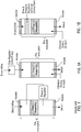
- Another aspect of this invention is a mechanically simple method to passively control the magnitude of the pressure differential across both ends of an evacuated hand-held tube-like device separated by a filter element as blood enters one end as shown on Fig. 1A and 1B .
- Another aspect of this invention is a mechanically simple method to passively control the rate of change of the pressure differential across both ends of an evacuated hand-held tube-like device separated by a filter element as blood enters one end as shown on Fig. 1A and 1B .
- Another aspect of this invention is a mechanically simple method to passively control the magnitude of the pressure differential across both ends of an evacuated hand-held tube-like device separated by a filter element by controlling the rate of entry of the blood into the device as shown on Fig 1A .
- Another aspect of this invention is a mechanically simple method to passively control the rate of change of the pressure differential across both ends of an evacuated hand-held tube-like device separated by a filter element by controlling the rate of entry of the blood into the device as shown on Fig. 1A .
- Another aspect of this invention is an evacuated hand-held tube-like device holding in its central region a filter element and a flow rate controlling element constructed such that as blood enters the device via the flow rate controlling element the magnitude of the pressure differential across the filter element is controlled by the flow rate control element as shown on Fig. 1B .
- Another aspect of this invention is an evacuated hand-held tube-like device holding in its central region a filter element and a flow rate controlling element constructed such that as blood enters the device via the flow rate controlling element the rate of change of the pressure differential across the filter element is controlled by the flow rate control element as shown on Fig. 1B .
- the device is intended to be used instead of a common pre-evacuated blood collection device such as a BD VacutainerTM and can deliver serum or plasma by filtration directly without use of a centrifuge. It incorporates a flow rate control section preceding the filter, which may be internal to the evacuated tube or external. Blood is drawn into the partially evacuated device and with appropriate flow rate traverses to and through a filter assembly that captures cells but permits serum or plasma to flow through into a collection chamber.
- a flow rate control section preceding the filter, which may be internal to the evacuated tube or external. Blood is drawn into the partially evacuated device and with appropriate flow rate traverses to and through a filter assembly that captures cells but permits serum or plasma to flow through into a collection chamber.
- the device enables simple and rapid extraction of blood serum or plasma in milliliter quantities from a collected blood sample.
- the device can also provide for the addition of an agent that may coat the filter or the tube. Syringe extraction of blood serum from the device can be achieved via an access septum located at the downstream end of the collection tube.
- the device permits all functions to be performed rapidly, without exposure of personnel to needles, and with minimum danger of exposure of the operator to the sample or contamination of the sample while enabling standard evacuated collection tube methods to be used.
- the invention is a blood separation device in the form of a cylindrical tubular assembly similar in shape to a 6 ml VacutainerTM. It incorporates an input flow rate control element and from a drawn blood sample somewhat smaller than 2 milliliter produces approximately a 0.25 milliliter volume of blood serum practically free of hemoglobin.
- the input flow rate control element may be internal to the tube-like device.
- the input flow rate control element may be external to the tube-like device.
- the invention incorporates, within the blood input chamber, an elastically compressible element such as a closed cell member of resilient plastic or rubber foam or an air-filled bladder that regulates the rate of evolution of the pressure difference across the filter assembly as blood enters the region of the compressible element.
- an elastically compressible element such as a closed cell member of resilient plastic or rubber foam or an air-filled bladder that regulates the rate of evolution of the pressure difference across the filter assembly as blood enters the region of the compressible element.
- neither air nor gas is permitted to enter any part of the device until the filtration process has been completed and the serum chamber has been brought to atmospheric pressure by letting air at atmospheric pressure enter through the serum access septum or through an equivalent port. That process takes approximately 1 or 2 minutes.
- Another aspect of this invention is a mechanically simple method to passively control the magnitude of the pressure differential across both ends of pressurized hand-held tube-like device separated by a filter element as blood enters one end as shown on Fig. 1D and 1E .
- Another aspect of this invention is a mechanically simple method to passively control the rate of change of the pressure differential across both ends of an evacuated hand-held tube-like device separated by a filter element as blood enters one end as shown on Fig. 1D and 1E .
- Another aspect of this invention is a mechanically simple method to passively control the magnitude of the pressure differential across both ends of a pressurized hand-held tube-like device separated by a filter element by controlling the rate of entry of the blood into the device as shown on Fig 1C .
- Another aspect of this invention is a mechanically simple method to passively control the rate of change of the pressure differential across both ends of a pressurized hand-held tube-like device separated by a filter element by controlling the rate of entry of the blood into the device as shown on Fig. 1C .
- the independent blood filter device depends on flow geometry to deliver blood serum or plasma free of detrimental levels of hemoglobin. It depends critically on an upstream flow rate or pressure differential limiting control element or device that limits the rate of change of pressure differential across the filter element.
- Pre-evacuated versions can be used to simultaneously draw blood from a living being and provide pressure differential across the filter element between an evacuated collector and a supply end open to atmosphere.
- a unit can be pressurized by hand motion employing the external shape of a partially filled blood collection tube as a piston to produce pressure in advance of the control element or device to create the pressure differential across the filter element to a collector vented to atmosphere.
- the control element or device is disclosed in numerous forms, including specially sized flow constrictions and compliant arrangements.
- Preferred implementations of this aspect of the invention may incorporate one or more of the following:
- the pressure differential across the filter may be limited to below 30 mmHg per second.
- the pressure differential across the filter may be limited to below 20 mmHg per second.
- the flow rate through the filter may be approximately 2 to 10 cc per minute.
- the flow rate may be between 3 to 6 cc per minute.
- the device may be constructed to produce a volume of between about 1 to 2 cc filtrate.
- the device may be constructed to produce a volume of about 1.5 cc filtrate.
- the limiting control element or device may be a tubular element between 1 ⁇ 2 inch (1.27 cm) and 4 inches (10.16 cm) in length and may have an internal diameter between about .008 (0.020 cm) and .013 inch (0.033 cm).
- the invention comprises a method of obtaining blood serum or plasma using the filtering device according to the first aspect described alone or together with any of the further features mentioned.
- Figs. 1-6 the geometry of a flow rate or pressure differential limiting control element or device upstream of the filter is used to define conditions with pre-evacuated tubes.
- the tubes may be blood collection tubes.
- Figs. 7-9 the geometry is used in respect of a pressurized system.
- the present invention provides a filtering device for filtering blood to obtain serum or plasma in a container comprising: a pre-evacuated container including inlet and outlet ends with access at both ends, a filter located within the container, and a flow rate limiting control element or device located upstream of the filter and designed to limit pressure differential across the filter, the flow rate control element or device including capillary restriction for limiting blood flow while still enabling continuous blood flow into said pre-evacuated container and after said capillary restriction blood flowing unimpeded within the container toward the filter substantially eliminating hemolysis associated with the filter.
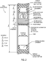
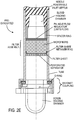
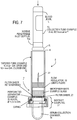
- the device comprises a tube-shaped assembly closed at each end with a needle-penetrable access septum.
- the blood inlet access septum located at one end of the tube connects for inlet of blood to the blood holding chamber and the outlet access septum located at the other end of the tube faces the serum/plasma collection chamber and can function as the air inlet port to terminate the filtration process.
- a filter assembly is fixed in place in the central region of the tube.
- a passive blood flow controlling segment may be located between the blood inlet access septum and the filter assembly ( Fig. 1B ) or may be external, preceding the device ( Fig. 1A).
- Figs. 1A and 1B illustrate flow geometries based on pre-evacuation of container or tubes. Preferred implementations are shown in Figs. 2-6 .
- Figs. 1C and 1D illustrate similar flow geometries based on pressurization of the container or tube, similar preferred implementations of which are shown in Figs. 1-9 .
- the inlet access septum is adapted for being pierced by a standard blood-collection needle assembly (needle penetrable) and defines one end of the chamber free to accept the blood sample for filtration.
- a flow rate regulating segment adjacent to this access septum regulates the rate of flow of blood approaching the filter assembly and defines the pressure differential driving the filtration process in the pre-evacuated unit.
- the filter assembly is preferably designed to cover the entire cross-section area of the tube.
- the filter assembly captures the cellular components of the blood and permits passage of the serum or plasma components.
- the filter assembly preferably terminates with a peripherally sealed element that prevents flow-around (bypass flow) of blood product and an axial retainer pressed or molded into place.
- the axial location of the filter assembly and starting point pressure (vacuum) level of the pre-evacuated device can be used to coordinate the pressure differential changes across the filter assembly.
- a volume of elastomeric compressible media or a resiliently collapsible element may be located in the chamber free to accept the blood sample as shown on Fig. 2F for modulating the pressure differential.
- closed cell silicone sponge or foam made of natural rubber, or Nitrile, with durometer less than Shore 45 may be used, or a partially air-filled bladder, for instance.
- the terminal end of the tube forms the low pressure chamber that induces the filtration process and is the serum collection chamber. It is closed with a second access septum through which atmospheric air can be caused to enter to equilibrate pressure across the filter assembly to terminate filtration, and for subsequent removal of filtered material via a needle and syringe.
- the serum collection access septum has a hollow space sized to hold all the filtrate and can be slide-ably removed from the tube for serum aspiration with a pipette.
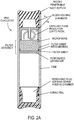
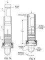
- the serum collection closure segment can be rigid and held in place with a simple pressed in O ring as shown on FIG. 2A or be detachable via a bayonet connector as shown on FIG. 2B to implement depressurization and access to the filtrate.
- a region adjacent to the blood inlet access septum of the tube is dedicated to hold the blood sample to be filtered until filtration has been performed and to retain all extraneous blood and blood components, liquid and gaseous.
- One aspect of the invention is the incorporation of an intake blood flow rate controller/regulator prior to the filtration stage, Fig. 1A .
- the controller/regulator of the rate of blood flows is located within the device, Fig. 1B .
- the flow rate controller/regulator limits the rate of blood flow that can enter the filter assembly.
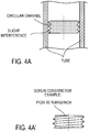
- controller/regulator/restrictor is located between the access septum and the filter assembly as shown on FIG. 2 D; FIGS. 4A and 4A' show details of the restrictor (constrictor).
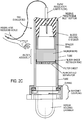
- the flow rate regulation function can be implemented externally from the tube-shaped assembly, Fig. 1A .
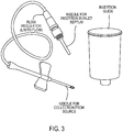
- a preferred implementation is shown on Fig. 2C and incorporated into the blood delivering needle assembly, Figs. 3 and 3A .
- the flow rate regulating function can be implemented at the inlet of the filter assembly or within the filter assembly or a combination of both.
- Preferred implementations have one or more of the following features:
- the device incorporates a filter or filter material assembly to which blood entering the upstream tube is exposed.
- the filter assembly may have 3 constituents:
- the filter assembly is retained and supported axially near the middle at the tube with a perforated screen member. Suitable glass fiber density is maintained by axial compression against such screen member.
- the section of the tube between the input access septum and the filter assembly offers a holding chamber for the incoming blood before it travels through the filtering material.
- the low-density glass fiber filter material catches blood cells gradually by entangling at first large blood cell components and then smaller blood cell components in the space structure while permitting smaller molecules to travel through.
- the invention teaches to deliver cells into and through the filter assembly with minimum and controllable force derived from a controlled pressure differential between the blood entering the filter assembly and the serum collection section of the tube.
- the pressure differential is controlled to induce a low velocity of the blood components beginning at the initial stage of filtering to minimize shear force on the cells, or impelling damage from collision with glass fibers of the filter assembly or with cell lodged in a tangle of glass fiber, in a manner to avoid excess hemolysis.
- red cells are robust when subjected to substantial pressure variations, but are very fragile in shear. This may explain why a slower flow rate reduces hemolysis.
- red blood cells can burst on impact with the glass fibers of the filter and that the impact damage can be reduced or eliminated if the inrush speed is kept low enough.
- cell damage is caused by a high pressure differential across the glass fiber filter, which squeezes the red cells in an extreme shear condition into the smaller filter channels causing greater shear stress that bursts the cells. In the latter instance, the longer a high pressure differential exists, the more red cell damage would occur.
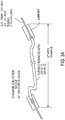
- Figures 5 and 6 show that a high pressure differential persists substantially longer when the inflow rate is higher.
- the present invention also teaches to deliver blood in a condition where early in the blood injection process a barrier is established between the parts of the tube on either side of the filter assembly. Blood entering the intake region of the filter assembly diffuses rapidly through the hydrophilic media and creates an air tight seal. Consequently the pressure condition in the tube downstream of the filter assembly is little altered by the blood injection. In contrast the pressure within the segment of the tube upstream from the filter assembly is substantially raised by the introduction of blood. This condition creates a pressure differential across the filter assembly that propels the small molecules contained in the serum to travel through the filter assembly.
- the invention teaches how to regulate the pressure differential across the filter assembly. This is best achieved by control of the rate of inflow of blood as it alters the pressure in the tube upstream from the filter assembly and more specifically the region of the tube in direct contact with the filter assembly.
- the filter assembly is in cooperative relationship with the blood which diffuses readily through it by surface tension as well as pressure differential. Hemolysis takes place as the blood travels through the filter and is strongly affected by the pressure forces and rate of flow through the filter assembly. Little if any hemolysis takes place as blood enters the intake reservoir, it is thought, based on voluminous experience with VacutainerTM type devices.
- P is the pressure of the gas
- V is the volume of the gas
- n is the amount of substance of gas (also known as number of moles)
- T is the temperature of the gas
- R is the ideal, or universal, gas constant, equal to the product of Boltzmann's constant and Avogadro's constant.
- n is measured in moles, and T in Kelvin.
- R has the value 8.314 J•K -1 •mo l -1 or 0.08206 L•atm•mol -1 •K -1 .
- Initial depressurization of both ends of the tube assembly may be from 250 to 700 mmHg. Atmospheric pressure is typically 760 mmHg. Blood, upon wetting the intake side of the filter media, establishes a gas-tight surface barrier almost immediately, preventing air exchange transport between the two ends of the tube. Measurements show that about 0.5 cc are sufficient to form a seal: this occurs within 6-8 seconds when flow rate is kept low enough to prevent hemolysis, and within 1-2 seconds at higher flow rates. Thus, if the blood continues to enter at a high rate of flow the trapped air is compressed and the pressure rises accordingly. The pressure in the tube upstream from the filter assembly can rise to near atmospheric pressure while the downstream pressure remains low.
- a slow rate of entry of the blood into the tube allows time for the blood to start passing through the filter media; trapped air will still be compressed by the incoming blood though much less so, resulting in a smaller pressure differential across the filter and thus minimal hemolysis.
- This pressure condition is exemplified on Fig 6 showing an average initial pressure differential rate of 13.3 mmHg /sec.
- Intake blood flow rates, initial pressure conditions, volumes of both segments, upstream and downstream from the filter assembly as well as the proper filter construction can be optimized to accommodate the range of plasma viscosity encountered in practice.
- the total volume of blood intake is limited to the free space upstream from the filter assembly less the volume of the filter material taking into consideration the serum filtered into the downstream tube.
- the serum filtration process is self-limiting and brief, 15 to 30 seconds typically.
- the entire device is at a low pressure level, possibly 100 mm Hg.
- the slow blood entry slowly fills the volume previously available to the air molecules and consequently the pressure within that space increases slowly according to the Ideal Gas Law.
- the device is similar to a 6 cc Vacutainer. It has uniform inside diameter of approximately 10.5 mm and wall thickness of approximately 1 mm.
- the blood entry chamber, flow regulator and filter assembly has a length of approximately 33 mm and the overall tube approximately 80 mm.
- the filter assembly is formed with approximately 0.35 gram of 108 A or 108 B Micro-Strand Glass Microfibers from Johns Manville or equivalent with nominal diameter 1.8 micron having a net density 0.15 and 0.5 and preferably approximately 0.027 gram per cubic centimeter. (In other embodiments 0.5 grams of the microfibers can be used, or within the 0.35 gram to 0.5 gram range, 0.415 grams bay be used.)
- the glass fiber segment may be covered at its entry with a highly hydrophilic filter layer such as PorexTM filter material POR 41210 or POR 4711 and at its exit with a 0.6 micron porosity filter.
- a highly hydrophilic filter layer such as PorexTM filter material POR 41210 or POR 4711
- filter material of 1.0 micron porosity may be used to take advantage of better tear properties that it may have.
- a flow control regulator is located between the blood entry access septum and the filter assembly segment. It can be a cup shaped thin cylindrical element holding in its center a capillary flexible tubing with 0.25 mm inside diameter and a length of 40 or 50 mm as shown on Figure 3A .
- the rate of blood flow entering the device through the access septum is quite low, approximately 0.05 cc/sec. to 0.1cc/sec and when the blood has approximately filled the accumulation segment the blood-collecting needle can be disconnected from the access septum in a manner that does not permit air or a gas to penetrate the device. This process takes form 15 to 30 seconds.
- the pressure differential acting on the blood against the filter assembly rises slowly in a passive manner to approximately 330mm Hg and settles to approximately 150 mmHg within 1 to 3 minutes when the serum separation can be finalized by permitting air at atmospheric pressure to enter the serum end of the tube.
- the blood gains a tendency to flow through the flow rate regulation segment and into the filter assembly and toward the downstream end of the tube.
- the flow rate regulator prevents rapid inrush of blood cells and serum molecules.
- the filter assembly captures cells and only permits through passage to molecules or particles smaller than .6 micron only serum or plasma or hemoglobin are allowed to pass through and accumulate into the downstream end of the tube. Thus, separation of the blood is performed shortly after it has been collected.
- the serum access septum can be pierced or separated for plasma collecting and further processing.
- the flow regulator device is preferably in the form equivalent to a length of channel of small cross section (though many times the width of blood cells).
- the blood flow rate needs to be such that blood entering the glass fiber filter section do not cause damage to the red cells previously located in the maze of glass fibers forming the main part of the filter.
- the flow control device permits a steady flow rate and prevents a burst flow from taking place. The process can accommodate the expected range of blood viscosities.
- the flow rate controller is incorporated in the blood-collection needle assembly and consists of a capillary restricted channel approximately 25 to 50 mm long a with diameter between 0.25mm and 0.30mm.
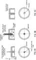
- the blood flow rate controller is in the form of a circular channel created when a screw is inserted in a smooth cylinder of mated diameter.
- the section of the channel thus created and its length - the number of turns times the diameter- limits the rate of flow possible for a fluid of defined viscosity and a defined pressure differential acting on the fluid.
- a screw constrictor is shown on FIG. 2D and Fig 4A .
- the channel in the preferred embodiment has a section equivalent to that of a tube of diameter 0.25mm and 0.30mm and a length 25 and 50 mm.
- the preferred flow rate is from approximately 2 to 10cc per minute and preferably 3 to 6 cc per minute to a volume of 1 to 2 cc preferably 1.5 cc.
- the Hagen-Poiseuille law instructs that the tubing should have an inner diameter of approximately 0.015 inches (0.0381 cm), considerably smaller than that of commercial blood drawing devices.
- An alternate design is the introduction of a section of tubing less than the full length of the blood drawing tube that has reduced diameter. According to a preferred implementation, a 2 to 4 inch (5.08 to 10.16 cm) section of 0.012 inch (0.03048 cm) diameter tubing is employed within the 12 inches (30.48 cm) length from needle to needle, as herein presented.
- the Hagen-Poiseuille law is applicable to Newtonian fluids. Blood is a non-Newtonian fluid and this is specially expressed when capillaries or rigid flow channels are either too narrow or too long. It has been verified experimentally that the Hagen-Poiseuille law is useful for the present purposes, and is especially applicable to the preferred flow constrictor, of the order of .011 inch (0.02794 cm) internal diameter and 2 inches (5.08 cm) length.
- Preferred dimensions for a tubular limiting control element are between about 1 ⁇ 2 inch (1.27 cm) and 4 inches (10.16 cm) in length and ID between about .008 and .013 inch (0.02032 and 0.03302 cm).
- the rate of increase of the pressure differential between the blood entry segment of the device and the serum collection segment can be regulated with the insertion of a compressible element working as an intake pressure buffer in the blood entry segment of the device.
- the rate of increase of the pressure differential between the blood entry segment of the device and the serum collection segment can be facilitated with appropriate volume relationships defined by the axial location of the filter assembly.
- the pressure differential across the filter assembly is obtainable by pressurizing the blood upstream of the control element or section to above atmospheric pressure and venting the downstream side of the filter assembly to atmosphere.
- the blood separator device may take the form of an open ended tube that precedes a filter assembly, into which the blood container slides. It makes sealed engagement with the tube wall to produce pumping action. During this action, the filter assembly and following filtrate collector are closed to the atmosphere. The motion of the container is employed to increase air pressure throughout the closed volume. Later, upon venting the filtrate collector, the air pressure above the blood in the container is employed to drive the blood through the control element or section and filter assembly into the then-vented collector.
- FIG. 7-9 an implementation is shown in which blood separating device 8 is used with a conventional evacuated collection tube 10 such as available from Becton Dickinson and Company under the trademark VacutainerTM).
- a conventional evacuated collection tube 10 such as available from Becton Dickinson and Company under the trademark VacutainerTM.
- the filtrate collector 14 is sealed to the body of the blood separator device 8.
- a user introduces the inverted collection tube 10 and presses it gently down into the larger tubular body 12 of the separator device 8 to pierce the septum 10a of the collection tube 10 with an opposed hypodermic needle 20 that forms a capillary flow regulator or control element.
- the downward stroke of the collection tube 10at first causes air only in the closed volume below to be compressed.
- the collection tube 10 may travel to be fully inserted in the separating device8. But when the septum 10a of the collection tube 10 reaches the protruding hypodermic needle 20 and is pierced by it, pressure within the device 8 and the collection tube 10 is equilibrated.
- the Serum Collection Chamber (filtrate collector) 14 is partially then opened, permitting air to escape from the collector and bringing the region downstream from the filter assembly F to atmospheric pressure, thus creating a pressure difference across filter assembly F.
- the compressed volume is small compared with the total original volume of the device.
- the "free" remaining volume of the device may be quite small.
- the "free remaining volume” consists of the Serum Collection Chamber 14 and the filter assembly F as well as the flow regulation assembly 20.
- the initial conditions when the collection tube is about to be introduced into the device P is atmospheric pressure.
- the inside diameter of the internal diameter of the main body is 11.0 mm at its open end is about equal to the diameter of the deformable septum of the evacuated collection tube (VacutainerTM) such that the collection tube can be inserted without difficulty with alignment to its full length of 50.5 mm.
- the inner diameter of the main body 12 is slightly tapered such that it can easily be manufactured by injection molding or otherwise. If the inside diameter of the main body, 50 mm downward from the entry level is 10.5 mm, the volume of air displaced by the insertion of the collection tube is 4.58 cc.
- the serum collection chamber is approximately .5 cc and the void volume of the filter assembly approximately 1.0 cc with the pressure control and coupling region adding up to .75 cc, the total volume remaining adds to 2.25 cc.
- the original air volume was 6.83 cc.
- the "1.8 cc Vacutainer" has inner volume equal to 2.25 cc. and when filled with 1.8 cc of blood yields a void volume 0.45 cc.
- the flow rate or pressure differential limiting control element or device may take the form of a compliant tube wall section that tends to expand outward to increase volume in response to pressure. Accordingly, other embodiments are within the scope of the following claims.
Landscapes
- Health & Medical Sciences (AREA)
- Life Sciences & Earth Sciences (AREA)
- Engineering & Computer Science (AREA)
- Biomedical Technology (AREA)
- Hematology (AREA)
- Physics & Mathematics (AREA)
- General Health & Medical Sciences (AREA)
- Molecular Biology (AREA)
- Pathology (AREA)
- Heart & Thoracic Surgery (AREA)
- Biophysics (AREA)
- Animal Behavior & Ethology (AREA)
- Public Health (AREA)
- Veterinary Medicine (AREA)
- Surgery (AREA)
- Medical Informatics (AREA)
- Chemical & Material Sciences (AREA)
- Manufacturing & Machinery (AREA)
- Immunology (AREA)
- Urology & Nephrology (AREA)
- Food Science & Technology (AREA)
- Medicinal Chemistry (AREA)
- Analytical Chemistry (AREA)
- Biochemistry (AREA)
- General Physics & Mathematics (AREA)
- Water Supply & Treatment (AREA)
- Chemical Kinetics & Catalysis (AREA)
- Ecology (AREA)
- Vascular Medicine (AREA)
- Anesthesiology (AREA)
- Inorganic Chemistry (AREA)
- External Artificial Organs (AREA)
- Investigating Or Analysing Biological Materials (AREA)
- Measurement Of The Respiration, Hearing Ability, Form, And Blood Characteristics Of Living Organisms (AREA)
Applications Claiming Priority (3)
| Application Number | Priority Date | Filing Date | Title |
|---|---|---|---|
| US201261681823P | 2012-08-10 | 2012-08-10 | |
| US13/829,424 US9427707B2 (en) | 2012-08-10 | 2013-03-14 | Filtering blood |
| PCT/US2013/050260 WO2014025490A1 (en) | 2012-08-10 | 2013-07-12 | Filtering blood |
Publications (2)
| Publication Number | Publication Date |
|---|---|
| EP2882340A1 EP2882340A1 (en) | 2015-06-17 |
| EP2882340B1 true EP2882340B1 (en) | 2018-03-07 |
Family
ID=50065400
Family Applications (1)
| Application Number | Title | Priority Date | Filing Date |
|---|---|---|---|
| EP13741946.1A Active EP2882340B1 (en) | 2012-08-10 | 2013-07-12 | Filtering blood |
Country Status (7)
| Country | Link |
|---|---|
| US (4) | US9427707B2 (enExample) |
| EP (1) | EP2882340B1 (enExample) |
| JP (1) | JP6359536B2 (enExample) |
| AU (1) | AU2013300110B2 (enExample) |
| CA (1) | CA2881634C (enExample) |
| ES (1) | ES2670934T3 (enExample) |
| WO (1) | WO2014025490A1 (enExample) |
Families Citing this family (33)
| Publication number | Priority date | Publication date | Assignee | Title |
|---|---|---|---|---|
| US20130211289A1 (en) | 2012-01-25 | 2013-08-15 | Tasso, Inc. | Handheld Device for Drawing, Collecting, and Analyzing Bodily Fluid |
| AU2013293078B2 (en) | 2012-07-23 | 2017-09-07 | Tasso, Inc. | Methods, systems, and devices relating to open microfluidic channels |
| EP3769682B1 (en) | 2014-08-01 | 2024-01-03 | Tasso, Inc. | Systems for gravity-enhanced microfluidic collection, handling and transferring of fluids |
| US10779757B2 (en) | 2014-08-01 | 2020-09-22 | Tasso, Inc. | Devices, systems and methods for gravity-enhanced microfluidic collection, handling and transferring of fluids |
| CA2935312C (en) | 2014-10-14 | 2022-11-22 | Becton, Dickinson And Company | Blood sample management using open cell foam |
| CN209221880U (zh) | 2015-06-08 | 2019-08-09 | 贝克顿·迪金森公司 | 用于生物样品的过滤单元 |
| US10426390B2 (en) | 2015-12-21 | 2019-10-01 | Tasso, Inc. | Devices, systems and methods for actuation and retraction in fluid collection |
| AU2017227802B2 (en) | 2016-03-02 | 2020-11-12 | Becton, Dickinson And Company | Biological fluid separation device |
| EP3469358B1 (en) * | 2016-06-09 | 2025-10-22 | Becton, Dickinson and Company | Biological fluid separation device |
| EP4241888B1 (en) | 2017-06-08 | 2025-08-27 | Becton, Dickinson and Company | Biological fluid separation device |
| AU2019282329B2 (en) | 2018-06-07 | 2022-06-30 | Becton, Dickinson And Company | Biological fluid separation device |
| US11986297B2 (en) | 2018-06-14 | 2024-05-21 | Becton, Dickinson And Company | Atmospheric-balanced vacuum for blood gas sample stabilization with an evacuated container |
| JP2021531059A (ja) | 2018-07-09 | 2021-11-18 | ハヌマン ペリカン,インコーポレイテッド | 血液を処理するための装置および方法 |
| CN111657965B (zh) | 2018-09-14 | 2024-03-22 | 塔索公司 | 体液收集装置及相关方法 |
| MX2021006613A (es) | 2018-12-07 | 2021-07-07 | Siemens Healthcare Diagnostics Inc | Dispositivo con una funcion de evaluacion de componentes fluidos. |
| DE102018132710A1 (de) * | 2018-12-18 | 2020-06-18 | Analytik Jena Ag | Filtrierverfahren geeignet zur Isolierung und/oder Quantifizierung zumindest einer zu untersuchenden Substanz aus einer Probe |
| WO2020146178A1 (en) | 2019-01-07 | 2020-07-16 | Montagu Jean I | Controlling blood flow |
| US11439333B2 (en) | 2019-01-18 | 2022-09-13 | Becton, Dickinson And Company | Blood collection system including a baffle |
| JP7228676B2 (ja) | 2019-03-25 | 2023-02-24 | 富士フイルム株式会社 | 生体試料分離器具 |
| JP7158565B2 (ja) * | 2019-03-25 | 2022-10-21 | 富士フイルム株式会社 | 生体試料分離器具 |
| CA3147512C (en) | 2019-07-19 | 2024-04-02 | Siemens Healthcare Diagnostics Inc. | Tangent flow hemolysis detection blood testing device |
| US20210128037A1 (en) * | 2019-10-30 | 2021-05-06 | Becton, Dickinson And Company | Blood collection system with user-adjusted pressure management and related methods |
| US20210186394A1 (en) * | 2019-12-20 | 2021-06-24 | Becton, Dickinson And Company | Catheter extension set and related methods |
| US20210228127A1 (en) * | 2020-01-24 | 2021-07-29 | Becton, Dickinson And Company | Blood collection adapter and related devices to reduce hemolysis |
| US11014025B1 (en) * | 2020-03-06 | 2021-05-25 | Kevin-Steven Creagh Buford | Pressurized filtration system and device for rapid extraction and recycling of medication from body fluid |
| JP7577301B2 (ja) * | 2020-09-23 | 2024-11-05 | 株式会社Provigate | 液体試料処理装置 |
| JP2023548656A (ja) | 2020-10-08 | 2023-11-20 | ベクトン・ディキンソン・アンド・カンパニー | 統合された流体フラッシング機構を備えたプローブアセンブリを有する静脈内カテーテルデバイス |
| MX2023004163A (es) | 2020-10-12 | 2023-05-03 | Becton Dickinson Co | Jeringa para extraer sangre con proteccion frente a hemolisis. |
| CN114214180B (zh) * | 2021-12-10 | 2025-03-07 | 上海血液生物医药有限责任公司 | 一种儿童血液病检验用细胞分离提取装置 |
| EP4448179A1 (en) | 2021-12-17 | 2024-10-23 | Abbott Laboratories | Systems and methods for determining uch-l1, gfap, and other biomarkers in blood samples |
| CN120167040A (zh) | 2022-06-29 | 2025-06-17 | 雅培实验室 | 用于确定生物样本中的gfap的磁性定点照护型系统和测定 |
| WO2024015511A1 (en) * | 2022-07-13 | 2024-01-18 | University Of Pittsburgh-Of The Commonwealth System Of Higher Education | Methods and device related to removal of cell-free plasma hemoglobin |
| WO2026006069A1 (en) * | 2024-06-26 | 2026-01-02 | Becton, Dickinson And Company | System for point-of-care blood sampling and centrifuge-free plasma or serum separation |
Family Cites Families (55)
| Publication number | Priority date | Publication date | Assignee | Title |
|---|---|---|---|---|
| US2460641A (en) | 1945-08-14 | 1949-02-01 | Joseph J Kleiner | Blood collecting apparatus |
| US3814258A (en) | 1973-03-15 | 1974-06-04 | Dickinson And Co | Blood plasma separator with filter |
| US4212742A (en) * | 1978-05-25 | 1980-07-15 | United States Of America | Filtration apparatus for separating blood cell-containing liquid suspensions |
| DE3029579C2 (de) | 1980-08-05 | 1985-12-12 | Boehringer Mannheim Gmbh, 6800 Mannheim | Verfahren und Mittel zur Abtrennung von Plasma oder Serum aus Vollblut |
| US4343705A (en) | 1980-10-31 | 1982-08-10 | Instrumentation Laboratory | Biological liquid fractionation using alternate opposite flow directions across a membrane |
| US4540492A (en) | 1981-11-16 | 1985-09-10 | Millipore Corporation | Method and apparatus for treating whole blood |
| US4492634A (en) * | 1982-09-28 | 1985-01-08 | Emde Medical Research | Pre-evacuated blood collection tube with anti-hemolysis baffle system and centrifugation propelled filtration disc and efficient serum-from cells separator |
| US4906375A (en) | 1984-07-14 | 1990-03-06 | Fresenius, Ag | Asymmetrical microporous hollow fiber for hemodialysis |
| US4828716A (en) | 1987-04-03 | 1989-05-09 | Andronic Devices, Ltd. | Apparatus and method for separating phases of blood |
| US5030341A (en) | 1987-04-03 | 1991-07-09 | Andronic Technologies, Inc. | Apparatus for separating phases of blood |
| US4883068A (en) | 1988-03-14 | 1989-11-28 | Dec In Tech, Inc. | Blood sampling device and method |
| US5423989A (en) * | 1988-05-19 | 1995-06-13 | Chemtrack, Inc. | Plasma forming device |
| US5301685A (en) | 1989-01-10 | 1994-04-12 | Guirguis Raouf A | Method and apparatus for obtaining a cytology monolayer |
| US4961432A (en) | 1989-01-10 | 1990-10-09 | Cancer Diagnostics, Inc. | Modular fluid sample preparation assembly |
| US5211310A (en) | 1991-04-30 | 1993-05-18 | Andronic Devices Ltd. | Apparatus and method for dispensing phases of blood |
| US5555920A (en) | 1991-04-30 | 1996-09-17 | Automed Corporation | Method and apparatus for aliquotting blood serum or blood plasma |
| US5181940A (en) | 1991-08-01 | 1993-01-26 | Union Carbide Industrial Gases Technology Corporation | Hollow fiber membranes |
| JPH05188053A (ja) | 1992-01-10 | 1993-07-27 | Sanwa Kagaku Kenkyusho Co Ltd | 血液から血清又は血漿成分を分離する器具 |
| US5308508A (en) | 1992-05-15 | 1994-05-03 | Womack International, Inc. | High capacity filter media, method of use in filtration and method of formation |
| CA2156226C (en) | 1994-08-25 | 1999-02-23 | Takayuki Taguchi | Biological fluid analyzing device and method |
| GB9426251D0 (en) | 1994-12-24 | 1995-02-22 | Fsm Technologies Ltd | Device |
| CA2177442A1 (en) | 1995-05-29 | 1996-11-30 | Massimo Fini | Cardiotomy reservoir with internal filter |
| AU704863B2 (en) | 1995-11-15 | 1999-05-06 | Arkray, Inc. | Device and method for assaying biological components in sample |
| JPH09196911A (ja) | 1996-01-19 | 1997-07-31 | Fuji Photo Film Co Ltd | 血液濾過ユニット |
| JP3664328B2 (ja) | 1996-01-19 | 2005-06-22 | 富士写真フイルム株式会社 | 血漿または血清試料の調製方法 |
| JP3685283B2 (ja) | 1997-02-13 | 2005-08-17 | 富士写真フイルム株式会社 | 血漿採取具 |
| JP3903098B2 (ja) | 1997-07-18 | 2007-04-11 | 富士フイルム株式会社 | 血液濾過方法 |
| US6506167B1 (en) | 1997-12-24 | 2003-01-14 | I-Design Co., Ltd. | Blood-collecting tubes |
| JPH11237378A (ja) | 1998-02-19 | 1999-08-31 | Fuji Photo Film Co Ltd | 全血から血清を分離する方法 |
| FR2777698B1 (fr) | 1998-04-16 | 2000-05-12 | Alsthom Cge Alcatel | Separateur comprenant une matrice macroporeuse et un polymere poreux, son procede de fabrication, generateur electrochimique le comprenant et le procede de fabrication de celui-ci |
| DE19835721A1 (de) | 1998-08-07 | 2000-02-10 | Edi Experimentelle & Diagnosti | Verfahren zur Bestimmung der Immunabwehr des Blutes sowie Testkit hierfür und Verwendung eines geeigneten Spritzenzylinders |
| US6516953B1 (en) | 1998-12-05 | 2003-02-11 | Becton, Dickinson And Company | Device for separating components of a fluid sample |
| US6479298B1 (en) | 1998-12-05 | 2002-11-12 | Becton, Dickinson And Company | Device and method for separating components of a fluid sample |
| US6406671B1 (en) | 1998-12-05 | 2002-06-18 | Becton, Dickinson And Company | Device and method for separating components of a fluid sample |
| US6497325B1 (en) | 1998-12-05 | 2002-12-24 | Becton Dickinson And Company | Device for separating components of a fluid sample |
| US6264619B1 (en) * | 1999-09-01 | 2001-07-24 | Becton, Dickinson And Company | Kit for drawing a blood sample |
| US6471069B2 (en) | 1999-12-03 | 2002-10-29 | Becton Dickinson And Company | Device for separating components of a fluid sample |
| US6803022B2 (en) | 1999-12-06 | 2004-10-12 | Becton, Dickinson And Company | Device and method for separating components of a fluid sample |
| US6537503B1 (en) | 1999-12-03 | 2003-03-25 | Becton Dickinson And Company | Device and method for separating components of a fluid sample |
| JP2001321368A (ja) | 2000-05-16 | 2001-11-20 | Fuji Photo Film Co Ltd | 血漿採取具 |
| US6659288B2 (en) | 2000-05-16 | 2003-12-09 | Fuji Photo Film Co., Ltd. | Plasma- or serum-collecting device |
| US6465256B1 (en) | 2000-08-26 | 2002-10-15 | Becton, Dickinson And Company | Device and method for separating components of a fluid sample |
| CN100386441C (zh) | 2000-11-08 | 2008-05-07 | 贝克顿迪肯森公司 | 收集和稳定生物样品的装置、抑制体外基因诱导的方法和制备全血样品的方法 |
| US6890435B2 (en) | 2002-01-28 | 2005-05-10 | Koch Membrane Systems | Hollow fiber microfiltration membranes and a method of making these membranes |
| US6755802B2 (en) | 2002-05-06 | 2004-06-29 | Beckman Coulter, Inc. | Whole blood sampling device |
| KR101005970B1 (ko) | 2002-11-19 | 2011-01-05 | 가부시키가이샤 아이 디자인 | 혈장 또는 혈청 분리막, 및 혈장 또는 혈청 분리막을이용한 필터 장치 |
| AU2003900033A0 (en) * | 2003-01-07 | 2003-01-23 | Procork Pty Ltd | Container stopper |
| KR20060005390A (ko) | 2003-04-25 | 2006-01-17 | 세키스이가가쿠 고교가부시키가이샤 | 검체 채취용 용기를 이용한 검체 여과 방법, 치구 및 검체채취용 용기 |
| WO2007000986A1 (ja) | 2005-06-27 | 2007-01-04 | Sekisui Chemical Co., Ltd. | 血液分離フィルタ装置、および真空検体採取管 |
| JP2007003481A (ja) | 2005-06-27 | 2007-01-11 | Sekisui Chem Co Ltd | 血液分離装置 |
| JP2007000536A (ja) | 2005-06-27 | 2007-01-11 | Sekisui Chem Co Ltd | 真空検体採取容器 |
| WO2007000966A1 (ja) | 2005-06-27 | 2007-01-04 | Sekisui Chemical Co., Ltd. | 検体採取容器 |
| JP5240945B2 (ja) | 2006-11-28 | 2013-07-17 | ピクター リミテッド | アッセイ膜およびその使用法 |
| JP2008232876A (ja) | 2007-03-22 | 2008-10-02 | Sekisui Chem Co Ltd | 血球停止膜、血液分離フィルタ、血液分離装置及び検体採取容器 |
| US20100093551A1 (en) | 2008-10-09 | 2010-04-15 | Decision Biomarkers, Inc. | Liquid Transfer and Filter System |
-
2013
- 2013-03-14 US US13/829,424 patent/US9427707B2/en not_active Expired - Fee Related
- 2013-07-12 EP EP13741946.1A patent/EP2882340B1/en active Active
- 2013-07-12 CA CA2881634A patent/CA2881634C/en active Active
- 2013-07-12 WO PCT/US2013/050260 patent/WO2014025490A1/en not_active Ceased
- 2013-07-12 JP JP2015526543A patent/JP6359536B2/ja not_active Expired - Fee Related
- 2013-07-12 AU AU2013300110A patent/AU2013300110B2/en not_active Ceased
- 2013-07-12 ES ES13741946.1T patent/ES2670934T3/es active Active
-
2016
- 2016-08-27 US US15/330,225 patent/US10531822B2/en active Active
-
2020
- 2020-01-11 US US16/602,992 patent/US20200375518A1/en not_active Abandoned
-
2022
- 2022-02-07 US US17/803,101 patent/US11766202B2/en active Active
Also Published As
| Publication number | Publication date |
|---|---|
| JP6359536B2 (ja) | 2018-07-18 |
| US11766202B2 (en) | 2023-09-26 |
| US20220330859A1 (en) | 2022-10-20 |
| US20200375518A1 (en) | 2020-12-03 |
| CA2881634C (en) | 2021-11-23 |
| EP2882340A1 (en) | 2015-06-17 |
| AU2013300110B2 (en) | 2018-11-08 |
| ES2670934T3 (es) | 2018-06-04 |
| WO2014025490A1 (en) | 2014-02-13 |
| US10531822B2 (en) | 2020-01-14 |
| US20140042094A1 (en) | 2014-02-13 |
| CA2881634A1 (en) | 2014-02-13 |
| US20170065217A1 (en) | 2017-03-09 |
| JP2015528328A (ja) | 2015-09-28 |
| AU2013300110A1 (en) | 2015-03-26 |
| US9427707B2 (en) | 2016-08-30 |
Similar Documents
| Publication | Publication Date | Title |
|---|---|---|
| US11766202B2 (en) | Filtering in pre-evacuated containers | |
| JP7500671B2 (ja) | 生物学的流体分離デバイス | |
| JP6799043B2 (ja) | 生物体液の極微標本管理装置 | |
| CN102803958B (zh) | 血液过滤器以及过滤血液的方法 | |
| JPS61144571A (ja) | 液体標本の細胞状成分と非細胞状成分の自動分離装置 | |
| KR102512973B1 (ko) | 생물학적 유체 분리 장치 | |
| JP2004325412A (ja) | 血液検査用容器 |
Legal Events
| Date | Code | Title | Description |
|---|---|---|---|
| PUAI | Public reference made under article 153(3) epc to a published international application that has entered the european phase |
Free format text: ORIGINAL CODE: 0009012 |
|
| 17P | Request for examination filed |
Effective date: 20150309 |
|
| AK | Designated contracting states |
Kind code of ref document: A1 Designated state(s): AL AT BE BG CH CY CZ DE DK EE ES FI FR GB GR HR HU IE IS IT LI LT LU LV MC MK MT NL NO PL PT RO RS SE SI SK SM TR |
|
| AX | Request for extension of the european patent |
Extension state: BA ME |
|
| RIN1 | Information on inventor provided before grant (corrected) |
Inventor name: BELL, WILLIAM Inventor name: MONTAGU, SASHA |
|
| DAX | Request for extension of the european patent (deleted) | ||
| REG | Reference to a national code |
Ref country code: DE Ref legal event code: R079 Ref document number: 602013034053 Country of ref document: DE Free format text: PREVIOUS MAIN CLASS: A61B0005150000 Ipc: A61B0005154000 |
|
| GRAP | Despatch of communication of intention to grant a patent |
Free format text: ORIGINAL CODE: EPIDOSNIGR1 |
|
| RIC1 | Information provided on ipc code assigned before grant |
Ipc: A61B 5/153 20060101ALI20170713BHEP Ipc: A61B 5/154 20060101AFI20170713BHEP Ipc: B01D 61/22 20060101ALI20170713BHEP Ipc: A61B 5/155 20060101ALI20170713BHEP Ipc: G01N 33/49 20060101ALI20170713BHEP Ipc: B01D 71/04 20060101ALI20170713BHEP Ipc: A61B 5/15 20060101ALI20170713BHEP |
|
| INTG | Intention to grant announced |
Effective date: 20170814 |
|
| RIN1 | Information on inventor provided before grant (corrected) |
Inventor name: BELL, WILLIAM Inventor name: MONTAGU, JEAN I. Inventor name: MONTAGU, SASHA |
|
| GRAJ | Information related to disapproval of communication of intention to grant by the applicant or resumption of examination proceedings by the epo deleted |
Free format text: ORIGINAL CODE: EPIDOSDIGR1 |
|
| GRAR | Information related to intention to grant a patent recorded |
Free format text: ORIGINAL CODE: EPIDOSNIGR71 |
|
| GRAS | Grant fee paid |
Free format text: ORIGINAL CODE: EPIDOSNIGR3 |
|
| INTC | Intention to grant announced (deleted) | ||
| GRAA | (expected) grant |
Free format text: ORIGINAL CODE: 0009210 |
|
| INTG | Intention to grant announced |
Effective date: 20180124 |
|
| AK | Designated contracting states |
Kind code of ref document: B1 Designated state(s): AL AT BE BG CH CY CZ DE DK EE ES FI FR GB GR HR HU IE IS IT LI LT LU LV MC MK MT NL NO PL PT RO RS SE SI SK SM TR |
|
| REG | Reference to a national code |
Ref country code: GB Ref legal event code: FG4D |
|
| REG | Reference to a national code |
Ref country code: CH Ref legal event code: EP Ref country code: AT Ref legal event code: REF Ref document number: 975651 Country of ref document: AT Kind code of ref document: T Effective date: 20180315 |
|
| REG | Reference to a national code |
Ref country code: IE Ref legal event code: FG4D |
|
| REG | Reference to a national code |
Ref country code: DE Ref legal event code: R096 Ref document number: 602013034053 Country of ref document: DE |
|
| REG | Reference to a national code |
Ref country code: ES Ref legal event code: FG2A Ref document number: 2670934 Country of ref document: ES Kind code of ref document: T3 Effective date: 20180604 |
|
| REG | Reference to a national code |
Ref country code: CH Ref legal event code: NV Representative=s name: RIEDERER HASLER AND PARTNER PATENTANWAELTE AG, CH |
|
| REG | Reference to a national code |
Ref country code: NL Ref legal event code: MP Effective date: 20180307 |
|
| REG | Reference to a national code |
Ref country code: LT Ref legal event code: MG4D |
|
| REG | Reference to a national code |
Ref country code: FR Ref legal event code: PLFP Year of fee payment: 6 |
|
| PG25 | Lapsed in a contracting state [announced via postgrant information from national office to epo] |
Ref country code: FI Free format text: LAPSE BECAUSE OF FAILURE TO SUBMIT A TRANSLATION OF THE DESCRIPTION OR TO PAY THE FEE WITHIN THE PRESCRIBED TIME-LIMIT Effective date: 20180307 Ref country code: CY Free format text: LAPSE BECAUSE OF FAILURE TO SUBMIT A TRANSLATION OF THE DESCRIPTION OR TO PAY THE FEE WITHIN THE PRESCRIBED TIME-LIMIT Effective date: 20180307 Ref country code: NO Free format text: LAPSE BECAUSE OF FAILURE TO SUBMIT A TRANSLATION OF THE DESCRIPTION OR TO PAY THE FEE WITHIN THE PRESCRIBED TIME-LIMIT Effective date: 20180607 Ref country code: HR Free format text: LAPSE BECAUSE OF FAILURE TO SUBMIT A TRANSLATION OF THE DESCRIPTION OR TO PAY THE FEE WITHIN THE PRESCRIBED TIME-LIMIT Effective date: 20180307 Ref country code: LT Free format text: LAPSE BECAUSE OF FAILURE TO SUBMIT A TRANSLATION OF THE DESCRIPTION OR TO PAY THE FEE WITHIN THE PRESCRIBED TIME-LIMIT Effective date: 20180307 |
|
| REG | Reference to a national code |
Ref country code: AT Ref legal event code: MK05 Ref document number: 975651 Country of ref document: AT Kind code of ref document: T Effective date: 20180307 |
|
| PG25 | Lapsed in a contracting state [announced via postgrant information from national office to epo] |
Ref country code: GR Free format text: LAPSE BECAUSE OF FAILURE TO SUBMIT A TRANSLATION OF THE DESCRIPTION OR TO PAY THE FEE WITHIN THE PRESCRIBED TIME-LIMIT Effective date: 20180608 Ref country code: SE Free format text: LAPSE BECAUSE OF FAILURE TO SUBMIT A TRANSLATION OF THE DESCRIPTION OR TO PAY THE FEE WITHIN THE PRESCRIBED TIME-LIMIT Effective date: 20180307 Ref country code: RS Free format text: LAPSE BECAUSE OF FAILURE TO SUBMIT A TRANSLATION OF THE DESCRIPTION OR TO PAY THE FEE WITHIN THE PRESCRIBED TIME-LIMIT Effective date: 20180307 Ref country code: BG Free format text: LAPSE BECAUSE OF FAILURE TO SUBMIT A TRANSLATION OF THE DESCRIPTION OR TO PAY THE FEE WITHIN THE PRESCRIBED TIME-LIMIT Effective date: 20180607 Ref country code: LV Free format text: LAPSE BECAUSE OF FAILURE TO SUBMIT A TRANSLATION OF THE DESCRIPTION OR TO PAY THE FEE WITHIN THE PRESCRIBED TIME-LIMIT Effective date: 20180307 |
|
| PG25 | Lapsed in a contracting state [announced via postgrant information from national office to epo] |
Ref country code: NL Free format text: LAPSE BECAUSE OF FAILURE TO SUBMIT A TRANSLATION OF THE DESCRIPTION OR TO PAY THE FEE WITHIN THE PRESCRIBED TIME-LIMIT Effective date: 20180307 Ref country code: PL Free format text: LAPSE BECAUSE OF FAILURE TO SUBMIT A TRANSLATION OF THE DESCRIPTION OR TO PAY THE FEE WITHIN THE PRESCRIBED TIME-LIMIT Effective date: 20180307 Ref country code: EE Free format text: LAPSE BECAUSE OF FAILURE TO SUBMIT A TRANSLATION OF THE DESCRIPTION OR TO PAY THE FEE WITHIN THE PRESCRIBED TIME-LIMIT Effective date: 20180307 Ref country code: RO Free format text: LAPSE BECAUSE OF FAILURE TO SUBMIT A TRANSLATION OF THE DESCRIPTION OR TO PAY THE FEE WITHIN THE PRESCRIBED TIME-LIMIT Effective date: 20180307 Ref country code: AL Free format text: LAPSE BECAUSE OF FAILURE TO SUBMIT A TRANSLATION OF THE DESCRIPTION OR TO PAY THE FEE WITHIN THE PRESCRIBED TIME-LIMIT Effective date: 20180307 |
|
| PG25 | Lapsed in a contracting state [announced via postgrant information from national office to epo] |
Ref country code: CZ Free format text: LAPSE BECAUSE OF FAILURE TO SUBMIT A TRANSLATION OF THE DESCRIPTION OR TO PAY THE FEE WITHIN THE PRESCRIBED TIME-LIMIT Effective date: 20180307 Ref country code: SK Free format text: LAPSE BECAUSE OF FAILURE TO SUBMIT A TRANSLATION OF THE DESCRIPTION OR TO PAY THE FEE WITHIN THE PRESCRIBED TIME-LIMIT Effective date: 20180307 Ref country code: AT Free format text: LAPSE BECAUSE OF FAILURE TO SUBMIT A TRANSLATION OF THE DESCRIPTION OR TO PAY THE FEE WITHIN THE PRESCRIBED TIME-LIMIT Effective date: 20180307 Ref country code: SM Free format text: LAPSE BECAUSE OF FAILURE TO SUBMIT A TRANSLATION OF THE DESCRIPTION OR TO PAY THE FEE WITHIN THE PRESCRIBED TIME-LIMIT Effective date: 20180307 |
|
| REG | Reference to a national code |
Ref country code: DE Ref legal event code: R097 Ref document number: 602013034053 Country of ref document: DE |
|
| PG25 | Lapsed in a contracting state [announced via postgrant information from national office to epo] |
Ref country code: PT Free format text: LAPSE BECAUSE OF FAILURE TO SUBMIT A TRANSLATION OF THE DESCRIPTION OR TO PAY THE FEE WITHIN THE PRESCRIBED TIME-LIMIT Effective date: 20180709 |
|
| PLBE | No opposition filed within time limit |
Free format text: ORIGINAL CODE: 0009261 |
|
| STAA | Information on the status of an ep patent application or granted ep patent |
Free format text: STATUS: NO OPPOSITION FILED WITHIN TIME LIMIT |
|
| PG25 | Lapsed in a contracting state [announced via postgrant information from national office to epo] |
Ref country code: DK Free format text: LAPSE BECAUSE OF FAILURE TO SUBMIT A TRANSLATION OF THE DESCRIPTION OR TO PAY THE FEE WITHIN THE PRESCRIBED TIME-LIMIT Effective date: 20180307 |
|
| 26N | No opposition filed |
Effective date: 20181210 |
|
| PG25 | Lapsed in a contracting state [announced via postgrant information from national office to epo] |
Ref country code: SI Free format text: LAPSE BECAUSE OF FAILURE TO SUBMIT A TRANSLATION OF THE DESCRIPTION OR TO PAY THE FEE WITHIN THE PRESCRIBED TIME-LIMIT Effective date: 20180307 |
|
| PG25 | Lapsed in a contracting state [announced via postgrant information from national office to epo] |
Ref country code: MC Free format text: LAPSE BECAUSE OF FAILURE TO SUBMIT A TRANSLATION OF THE DESCRIPTION OR TO PAY THE FEE WITHIN THE PRESCRIBED TIME-LIMIT Effective date: 20180307 Ref country code: LU Free format text: LAPSE BECAUSE OF NON-PAYMENT OF DUE FEES Effective date: 20180712 |
|
| REG | Reference to a national code |
Ref country code: BE Ref legal event code: MM Effective date: 20180731 |
|
| REG | Reference to a national code |
Ref country code: IE Ref legal event code: MM4A |
|
| PG25 | Lapsed in a contracting state [announced via postgrant information from national office to epo] |
Ref country code: IE Free format text: LAPSE BECAUSE OF NON-PAYMENT OF DUE FEES Effective date: 20180712 |
|
| PG25 | Lapsed in a contracting state [announced via postgrant information from national office to epo] |
Ref country code: BE Free format text: LAPSE BECAUSE OF NON-PAYMENT OF DUE FEES Effective date: 20180731 |
|
| PG25 | Lapsed in a contracting state [announced via postgrant information from national office to epo] |
Ref country code: MT Free format text: LAPSE BECAUSE OF NON-PAYMENT OF DUE FEES Effective date: 20180712 |
|
| PG25 | Lapsed in a contracting state [announced via postgrant information from national office to epo] |
Ref country code: TR Free format text: LAPSE BECAUSE OF FAILURE TO SUBMIT A TRANSLATION OF THE DESCRIPTION OR TO PAY THE FEE WITHIN THE PRESCRIBED TIME-LIMIT Effective date: 20180307 |
|
| PG25 | Lapsed in a contracting state [announced via postgrant information from national office to epo] |
Ref country code: HU Free format text: LAPSE BECAUSE OF FAILURE TO SUBMIT A TRANSLATION OF THE DESCRIPTION OR TO PAY THE FEE WITHIN THE PRESCRIBED TIME-LIMIT; INVALID AB INITIO Effective date: 20130712 |
|
| PG25 | Lapsed in a contracting state [announced via postgrant information from national office to epo] |
Ref country code: MK Free format text: LAPSE BECAUSE OF NON-PAYMENT OF DUE FEES Effective date: 20180307 |
|
| PG25 | Lapsed in a contracting state [announced via postgrant information from national office to epo] |
Ref country code: IS Free format text: LAPSE BECAUSE OF FAILURE TO SUBMIT A TRANSLATION OF THE DESCRIPTION OR TO PAY THE FEE WITHIN THE PRESCRIBED TIME-LIMIT Effective date: 20180707 |
|
| PGFP | Annual fee paid to national office [announced via postgrant information from national office to epo] |
Ref country code: IT Payment date: 20220727 Year of fee payment: 10 Ref country code: GB Payment date: 20220728 Year of fee payment: 10 Ref country code: ES Payment date: 20220824 Year of fee payment: 10 |
|
| PGFP | Annual fee paid to national office [announced via postgrant information from national office to epo] |
Ref country code: FR Payment date: 20220728 Year of fee payment: 10 |
|
| PGFP | Annual fee paid to national office [announced via postgrant information from national office to epo] |
Ref country code: CH Payment date: 20220830 Year of fee payment: 10 |
|
| PGFP | Annual fee paid to national office [announced via postgrant information from national office to epo] |
Ref country code: DE Payment date: 20230731 Year of fee payment: 11 |
|
| REG | Reference to a national code |
Ref country code: CH Ref legal event code: PL |
|
| GBPC | Gb: european patent ceased through non-payment of renewal fee |
Effective date: 20230712 |
|
| PG25 | Lapsed in a contracting state [announced via postgrant information from national office to epo] |
Ref country code: CH Free format text: LAPSE BECAUSE OF NON-PAYMENT OF DUE FEES Effective date: 20230731 Ref country code: GB Free format text: LAPSE BECAUSE OF NON-PAYMENT OF DUE FEES Effective date: 20230712 |
|
| PG25 | Lapsed in a contracting state [announced via postgrant information from national office to epo] |
Ref country code: FR Free format text: LAPSE BECAUSE OF NON-PAYMENT OF DUE FEES Effective date: 20230731 |
|
| PG25 | Lapsed in a contracting state [announced via postgrant information from national office to epo] |
Ref country code: IT Free format text: LAPSE BECAUSE OF NON-PAYMENT OF DUE FEES Effective date: 20230712 |
|
| REG | Reference to a national code |
Ref country code: ES Ref legal event code: FD2A Effective date: 20240830 |
|
| PG25 | Lapsed in a contracting state [announced via postgrant information from national office to epo] |
Ref country code: ES Free format text: LAPSE BECAUSE OF NON-PAYMENT OF DUE FEES Effective date: 20230713 |
|
| PG25 | Lapsed in a contracting state [announced via postgrant information from national office to epo] |
Ref country code: ES Free format text: LAPSE BECAUSE OF NON-PAYMENT OF DUE FEES Effective date: 20230713 |
|
| REG | Reference to a national code |
Ref country code: DE Ref legal event code: R119 Ref document number: 602013034053 Country of ref document: DE |
|
| PG25 | Lapsed in a contracting state [announced via postgrant information from national office to epo] |
Ref country code: DE Free format text: LAPSE BECAUSE OF NON-PAYMENT OF DUE FEES Effective date: 20250201 |