EP2873589A2 - Neigungslenkvorrichtung - Google Patents
Neigungslenkvorrichtung Download PDFInfo
- Publication number
- EP2873589A2 EP2873589A2 EP13817393.5A EP13817393A EP2873589A2 EP 2873589 A2 EP2873589 A2 EP 2873589A2 EP 13817393 A EP13817393 A EP 13817393A EP 2873589 A2 EP2873589 A2 EP 2873589A2
- Authority
- EP
- European Patent Office
- Prior art keywords
- portions
- buffer
- cam
- convex engaging
- engaging portion
- Prior art date
- Legal status (The legal status is an assumption and is not a legal conclusion. Google has not performed a legal analysis and makes no representation as to the accuracy of the status listed.)
- Granted
Links
Images







Classifications
-
- B—PERFORMING OPERATIONS; TRANSPORTING
- B62—LAND VEHICLES FOR TRAVELLING OTHERWISE THAN ON RAILS
- B62D—MOTOR VEHICLES; TRAILERS
- B62D1/00—Steering controls, i.e. means for initiating a change of direction of the vehicle
- B62D1/02—Steering controls, i.e. means for initiating a change of direction of the vehicle vehicle-mounted
- B62D1/16—Steering columns
- B62D1/18—Steering columns yieldable or adjustable, e.g. tiltable
- B62D1/187—Steering columns yieldable or adjustable, e.g. tiltable with tilt adjustment; with tilt and axial adjustment
-
- B—PERFORMING OPERATIONS; TRANSPORTING
- B62—LAND VEHICLES FOR TRAVELLING OTHERWISE THAN ON RAILS
- B62D—MOTOR VEHICLES; TRAILERS
- B62D1/00—Steering controls, i.e. means for initiating a change of direction of the vehicle
- B62D1/02—Steering controls, i.e. means for initiating a change of direction of the vehicle vehicle-mounted
- B62D1/16—Steering columns
- B62D1/18—Steering columns yieldable or adjustable, e.g. tiltable
- B62D1/184—Mechanisms for locking columns at selected positions
-
- B—PERFORMING OPERATIONS; TRANSPORTING
- B62—LAND VEHICLES FOR TRAVELLING OTHERWISE THAN ON RAILS
- B62D—MOTOR VEHICLES; TRAILERS
- B62D1/00—Steering controls, i.e. means for initiating a change of direction of the vehicle
- B62D1/02—Steering controls, i.e. means for initiating a change of direction of the vehicle vehicle-mounted
- B62D1/16—Steering columns
- B62D1/18—Steering columns yieldable or adjustable, e.g. tiltable
-
- B—PERFORMING OPERATIONS; TRANSPORTING
- B62—LAND VEHICLES FOR TRAVELLING OTHERWISE THAN ON RAILS
- B62D—MOTOR VEHICLES; TRAILERS
- B62D1/00—Steering controls, i.e. means for initiating a change of direction of the vehicle
- B62D1/02—Steering controls, i.e. means for initiating a change of direction of the vehicle vehicle-mounted
- B62D1/16—Steering columns
- B62D1/18—Steering columns yieldable or adjustable, e.g. tiltable
- B62D1/19—Steering columns yieldable or adjustable, e.g. tiltable incorporating energy-absorbing arrangements, e.g. by being yieldable or collapsible
- B62D1/195—Yieldable supports for the steering column
Definitions
- the present invention relates to a tilt steering apparatus that is provided with a tilt mechanism to adjust the height position of a steering wheel according to the physique and driving posture of a driver
- a steering apparatus for an automobile is constructed such that the rotation of a steering wheel 1 is transmitted to an input shaft 3 of a steering unit 2, and as the input shaft 3 rotates, a pair of tie rods 4 are pushed and pulled, which applies a steering angle to the front wheels
- the steering wheel 1 is supported by and fastened to the rear-end portion of a steering shaft 5, and that steering shaft 5 is inserted in the axial direction into a steering column 6 having a cylindrical shape, and is supported by the steering column 6 so as to be able to rotate freely.
- the front-end portion of the steering shaft 5 is connected to the rear-end portion of an intermediate shaft 8 by way of a universal joint 7, and the front-end portion of the intermediate shaft 8 is connected to the input shaft 3 by way of another universal joint 9
- an electric power steering apparatus is provided, and the front-end portion of the steering column 6 supports an electric motor 10 and is connected to a housing 11 that houses a reducer.
- the forward-backward direction, the left-right direction (width direction) and the up-down direction refer to the forward-backward direction, left-right direction (width direction) and up-down direction of a vehicle body in which the tilt steering apparatus is installed.
- a tilt mechanism to adjust the height position of the steering wheel 1 is normally assembled.
- a tilt steering apparatus in which a manual tilt mechanism is installed, is constructed so as to be able to change between an adjustable state in which the height position of the steering wheel 1 is adjustable according to the operation of an adjustment lever (not illustrated), and a state in which the adjusted height of the steering wheel 1 is maintained.
- a cam mechanism is assembled so as to improve the operational feeling of the adjustment lever, or a gear engaging means are installed in the tilt mechanism to strongly maintain the height position of the steering wheel 1.
- FIG. 14 to FIG 18 illustrate the construction as disclosed in JP 2012-040949 (A )
- This tilt steering apparatus has: a steering column 6a, a steering shaft 5a, a displacement-side bracket 12, a fixed-side bracket 13, an adjustment rod 14, a driven-side cam 15, a drive-side cam 16, an adjustment lever 17, a receiving bracket 18, a pivot arm 19, a pivot transmission portion 20, and buffer members 21a, 21b
- a telescopic function to adjust the forward-backward position is also provided.
- the steering column 6a is constructed such that the front portion of an inner column that is located on the rear side is fitted inside an outer column 22 that is located on the front side, so that the overall length of the steering column 6a can be expanded or contracted.
- the outer column 22 is formed into a U shape that is open on the top by bending metal plate, and restraining blocks 24 are fastened to the inside surfaces on the upper side of each
- the front portion of the inner column 23 is fitted inside a portion that is surrounded by the restraining blocks 24 and the bottom surface of the outer column 22 so as to be able to be displaced in the axial direction.
- the front-end portion of the outer column 22 is joined and connected to a housing 25 of a power steering apparatus in a state so as to protrude toward the rear from the housing 25
- a support tube 26 is supported by and fastened to the front top portion of the housing 25, and the housing 25 and steering column 6a are supported by the vehicle body by way of a tilt shaft (not illustrated) that is inserted through the support tube 26 so as to be able to be pivotally displaced
- the steering shaft 5a is constructed by fitting the rear portion of the inner shaft 27, that is located in the front side, with the front portion of the outer shaft 28 that is located in the rear side by a spline fit so as to be able to transmit torque, and the steering shaft 5a expands or contracts as the steering column 6a expands or contracts
- the steering shaft 5a is such that the rear-end portion protrudes toward the rear from the opening on the rear end of the steering column 6a, and supported on the inside of the steering column 6a so as to be able to rotate freely
- the portion near the rear end of the intermediate portion of the outer shaft 28 is supported on the inside of the rear-end portion of the inner column 23 by a bearing such as a single-row deep-groove ball bearing that supports radial loads and thrust loads.
- the output shaft 29 of the power steering apparatus is joined and fastened to the front-end portion of the inner shaft 27 by way of a torsion bar, and the output shaft 29 is supported on the inside of the housing 25 by a similar ball bearing
- the steering wheel 1 is fastened to the rear-end portion of the outer shaft 28.
- the displacement-side bracket 12 is constructed by the upper section of a pair of left and right side plate portions 30 of the outer column 22, and the retaining block 24 that is fastened to the inside surface on the upper side of these side-plate portions 30.
- Through holes 32 for inserting the rod portion 31 of the adjustment rod 14 are formed in the portions in the side plate portions 30 and restraining block 24 that are aligned with each other
- the fixed-side bracket 13 is formed by bending using press working or by die cast molding of a metal such as a steel plate or an aluminum alloy, and has: an installation plate portion 33 for supporting and fastening the fixed-side bracket 13 to the vehicle body, and a pair of support plate portions 34a, 34b for supporting the displacement-side bracket 12 with respect to the fixed-side bracket 13.
- the pair of support plate portions 34a, 34b are provided so as to be parallel with each other in a state separated in the width direction and hanging down from the installation plate portion 33 so as to hold the displacement-side bracket 12 from both sides in the width direction.
- Vertically long holes 35a, 35b having a partial arc shape that is centered around the tilt shaft are formed in portions of the pair of support plate portions 34a, 34b that are aligned with each other.
- the adjustment rod 14 is such that an outward-facing flange shaped anchor portion 37 is fastened to the base-end portion of the round rod shaped rod portion 31, and a male screw portion 38 is formed on the tip-end portion thereof.
- a convex engaging portion 39a that extends in the up-down direction is provided in a portion on the inside surface of the anchor portion 37 that surrounds the base-end portion of the rod portion 31.
- the convex engaging portion 39a is such that the width dimension in the forward-backward direction is slightly smaller than the width dimension in the forward-backward direction of the vertically long hole 35a that is provided in one of the support plate portions 34a, and the length dimension in the up-down direction is longer than the width dimension in the forward-backward direction of the vertically long hole 35a.
- the rod portion 31 of the adjustment rod 14 is inserted in the width direction through the vertically long holes 35a, 35b, and the through holes 32, and engages with the vertically long hole 35a of the one support plate portion 34a, and the inside surface of the anchor portion 37 comes in contact with the outside surface of the one support plate portion 34a.
- the male screw portion 38 of the rod portion 31 protrudes from the outside surface of the other support plate portion 34b.
- a buffer member 21a is fitted around the outside of the base-end portion of the rod portion 31.
- the buffer member 21a is made of synthetic resin and has a shape that covers both end surfaces on the top and bottom of the convex engaging portion 39a.
- a circular hole 40a for inserting the rod portion 31 through is provided in the center portion of the buffer member 21a, and buffer portions 41a are provided at both end portions on the top and bottom of the outside surface of the buffer member 21a.
- the driven-side cam 15 is formed by forging a metal material such as an iron-based alloy or by performing the necessary finishing of a sintered metal that was obtained by powder metallurgy, so as to have the required strength, rigidity and resistance to wear, and a convex engaging portion 39b is provided on the inside surface, a driven-side cam surface 42 is provided on the outside surface, and a through hole 43a that passes through in the axial direction is provided in the center portion thereof.
- the convex engaging portion 39b as in the case of the convex engaging portion 39a that is formed on the inside surface of the anchor portion 37, has a width dimension in the forward-backward direction that is slightly smaller than the width dimension in the forward-backward direction of the vertically long hole 35b that is provided in the other support plate portion 34b, and has a length dimension in the up-down direction that is larger than the width dimension in the forward-backward direction of the vertically long hole 35b.
- the buffer member 21b as in the case of the buffer member 21a, has a circular hole 40b and a pair of buffer portions 41b, where in a state in which these buffer portions 41b cover both end surfaces on the top and bottom of the convex engaging portion 39b, being mounted to the inside surface of the driven-side cam 15, and being fitted around the outside of the portion near the tip end of the intermediate portion of the rod portion 31 of the adjustment rod 14.
- the driven-side cam surface 42 is constructed such that an uneven surface is formed in the circumferential direction by making a convex portion, an inclined surface that is continuous in the circumferential direction with this convex portion, and a concave portion that is continuous in the circumferential direction of the inclined surface.
- the shape as seen from the axial direction of the through hole 43a is an elliptical shape.
- the tip-end portions of hook-shaped pieces 51 that protrude from both end portions in the width direction (forward-backward direction) of the center portions in the up-down direction of the outside surface of the buffer member 21b are engaged with the end edge portions of the driven-side cam surface 42 on both sides in the major axis direction of the through hole 43a, which prevents the driven-side cam 15 from coming apart from the buffer member 21b.
- the drive-side cam 16 is formed in the same way as the driven-side cam 15, with a drive-side cam surface 44 being provided on the inside surface thereof, and a circular through hole 43b that passes through in the axial direction being provided in the center portion thereof.
- the drive-side cam 16 is supported by the tip-end portion of the adjustment rod 14 in a state so as to be able to rotate centered around the adjustment rod 14, and such that displacement toward the tip-end side of the adjustment rod 14 is presented.
- a nut 45 is screwed onto the male screw portion 38 on the tip-end portion of the adjustment rod 14, and a thrust bearing 46 is placed between the inside surface of the nut 45 and the outside surface of the drive-side cam 16.
- the nut 45 is tightened to a specified torque, and then by crimping part (the outside end portion, for example) in the direction of the male screw portion 38, the nut 45 is prevented from becoming loose.
- crimping part the outside end portion, for example
- a cam apparatus 47 is formed that expands or contracts the dimension in the axial direction, or in other words, the distance in the axial direction between the outside surface of the drive-side cam 16 and the inside surface of the driven-side cam 15
- the adjustment lever 17 is formed by injection molding of synthetic resin that includes a high-function resin such as a polyamide or polyacetal, or is formed by die cast molding of a light alloy such as an aluminum alloy, and a concave holding portion 48 is provided in the base-end portion thereof
- the drive-side cam 16 is held inside the concave holding portion 48 in a state in which relative rotation with respect to the concave holding portion 48 is prevented such that the adjustment lever 17 is able to rotate and drive the drive-side cam 16
- An opening portion is provided in the bottom portion of the concave holding portion 48, which allows the outside surface of the drive-side cam 16 to come in direct contact with the thrust bearing 46. Therefore, the drive-side cam 16 and the base-end portion of the adjustment lever 17, and the adjustment rod 14 and the nut 45 are capable of relative rotation.
- the receiving bracket 18 is formed using a metal material that is able to maintain sufficient strength and rigidity, and being separated from the fixed-side bracket 13, is supported and fastened to the outside surface of the other support plate portion 34b by screws or the like
- the receiving bracket 18 is open in the front and in both the top and bottom ends, and has a concave groove 49 that extends in a direction along the vertically long hole 35b.
- the concave groove 49 is formed into a V shape such that the width at the opening portion is wide, and is inclined becoming narrower going toward the bottom.
- a female gear 50 which has a rack tooth shape with respect to the up-down direction, is provided on the inside surface of both sides of the concave groove 49.
- the pivot arm 19 is supported around the driven-side cam 15 such that relative rotation and a small amount of relative displacement in at least the up-down direction with respect to the driven-side cam 15 is possible.
- a support hole 52 having an inner diameter that is slightly larger than the outer diameter of the driven-side cam 15 is provided on the base-end portion of the pivot arm 19.
- a centering spring 53 is provided between the driven-side cam 15 and the base-end portion of the pivot arm 19.
- the driven-side cam 15 In a state in which there is no external force acting on the driven-side cam 15, the driven-side cam 15 is located in the center position in the up-down direction inside the support hole 52 due to the elastic force of the centering spring 53
- a male gear 54 that can engage or disengage with the female gear 50 on the inside surface of the concave groove 49 is provided on both side surfaces of the tip-end portion of the pivot arm 19
- the cross-sectional shape of the tip-end portion of the pivot arm 19 is a wedge shape, the thickness dimension of which becomes smaller going toward the tip edge of the portion where the male gear 54 is formed.
- the pivot transmission portion 20 is provided between the adjustment lever 17 and the pivot arm 19 so as to rotate the pivot arm 19 centered around the adjustment rod 14 together with the adjustment lever 17 Specifically, a protrusion 55 that is formed in the portion near the tip end of the outside surface of the pivot arm 19 is caused to gently engage with an concave engaging portion that is formed in the inside surface of part of the adjustment lever 17.
- the female gear 50 and male gear 54 engage with each other, however, when in the state in which the adjustment lever 17 is rotated downward and the dimension in the axial dimension of the cam apparatus 47 is contracted, the female gear 50 and male gear 54 become disengaged
- the height position of the steering wheel 1 is adjusted within the range in which the buffer members 21a, 21b can be displaced inside the vertically long holes 35a, 35b.
- the buffer portions 41a, 41b of the buffer members 21a, 21b that are made of synthetic resin come in contact with the top-end portion or bottom-end portion of the peripheral edge of the vertically long holes 35a, 35b.
- the occurrence of an impact or noise that is unpleasant for the driver that is operating the steering wheel 1 due to the impact between metal members is prevented.
- the adjustment lever 17 is rotated upward, which causes the convex portions of the drive-side cam surface 44 and the driven-side cam surface 42 to come face to face with each other, and the dimension in the axial direction of the cam apparatus 47 expands In this state, the surface pressure at the contact areas between the inside surfaces of the support plate portions 34a, 34b and the outside surface of the outer column 22 increases, and at the same time the surface pressure at the fitting portion between the outer column 22 and the inner column 23 also increases Moreover, the female gear 50 and the male gear 54 engage. When the steering wheel 1 is moved to a desired position, and the adjustment lever 17 is simply rotated upward does not absolutely mean that female gear 50 and the male gear 54 will engage.
- the pivot arm 19 on which the male gear 54 is provided is displaced in the up-down direction with respect to the driven-side cam 15 while causing the centering spring 53 to elastically deform, which causes the female gear 50 and the male gear 54 to engage
- the steering wheel 1 is maintained at the adjusted position
- the large maintaining force due to the engagement between the female gear 50 and the male gear 54 prevents the steering wheel 1 from jumping up
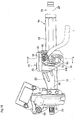
- FIG 19 illustrates construction that is disclosed in WO 2012/011424 (A1 ), however, in this construction, part of the pivot arm 19 is covered by a first buffer plate 60 and a second buffer plate 61 made of synthetic resin.
- the buffer members 21a, 21b lessen the impact that occurs when the top-end surfaces or bottom-end surfaces of the convex engaging portions 39a, 39b collide with the top-end surfaces or bottom-end surface of the peripheral edges of the vertically long holes 35a, 35b during up-down position adjustment of the steering wheel 1.
- the buffer portions 41a, 41b of the buffer members 21a, 21b cover both the top and bottom end surfaces of the convex engaging portions 39a, 39b, however, the center portion in the up-down direction of both side surfaces in the forward- backward direction of the convex engaging portions 39a, 39b are not recessed more than the buffer portions 41a, 41b and are exposed
- minute gaps for allowing the convex engaging portions 39a, 39b and buffer members 21a, 21b to move smoothly along the vertically long holes 35a, 35b are provided between the front-side edge 62 and rear-side edge 63 of the vertically long holes 35a, 35b, and both side surfaces in the front and rear of the convex engaging portions 39a, 39b and both side surfaces in the front and rear of the buffer members 21a, 21b Therefore, the convex engaging portions 39a, 39b and buffer members 21a, 21b can rotate centered around the adjustment rod 14 inside the vertically long holes 35a, 35b just the amount of the minute gaps.
- the driven-side cam 15 having convex engaging portions 39b on the inside surface thereof also rotates in the same direction just the amount of the minute gap.
- the adjustment lever 17 is rotated in the opposite direction of the tightening direction, the driven-side cam 15 rotates in the same direction just the amount of this minute gap.
- the vertically long holes 35a, 35b have a partial arc shape that is centered around the tilt shaft, so the front-side edges 62 of the peripheral edges of the vertically long holes 35a, 35b are convex arcs, and the rear-side edges 63 are concave arcs. Therefore, when the convex engaging portions 39a, 39b are pivotally displaced inside the vertically long holes 35a, 35b centered around the adjustment rod 14, there is a collision of the metal of the portions near both ends in the up-down direction of the side surfaces on the front side of the convex engaging portions 39a, 39b, and the front-side edges 62 of the vertically long holes 35a, 35b.
- the convex engaging portion 39b that is formed on the inside surface of the driven-side cam 15 the amount of this collision can easily become severe.
- the reason for this is that due to the engagement between the inclined surfaces of the driven-side cam surface 42 and the drive-side cam surface 44 during the process of operating the adjustment lever 17, regardless of the intention of the driver that operates the adjustment lever 17, it is easy for the adjustment lever to rotate with much energy.
- both end portions in the front and rear of the buffer portion 41b of the buffer member 21b protrude toward the front and rear further than both side surfaces in the front and rear of the convex engaging portion 39b, such that only both end portions in the front and rear of the buffer portion 41b will come in contact with the edges 62, 63 on both the front and rear sides of the vertically long hole 35b in a pre-loaded state
- looseness in the direction of rotation between the convex engaging portions 39b and the buffer member 21b is eliminated, so the driver that operates the adjustment lever 17 does not experience a feeling of looseness, and it is possible to prevent collision between metal members.
- the end surfaces of the buffer portion 41b that face each other are surfaces that do not have any stepped portion, and they face approximately in the up-down direction.
- the end surfaces of the buffer portion 41b that face each other face in a direction so as not to be able to efficiently support the rotation force in the tightening direction of the drive-side cam 16 (force in the circumferential direction centered around the adjustment rod 14). Therefore, there is a possibility that this rotation force will damage the buffer portion 41b, or that the shock absorbing function of the buffer portion 41b will be lost
- JP 2008-307959 (A ) discloses construction of a driven-side cam in which the cam surface portion is formed using a metal material, and the convex engaging portion are made of synthetic resin With this construction, it is possible to prevent the occurrence of noise that is caused by contact between metal of the driven-side cam and the support plate portions.
- the entire convex engaging portions of the driven-side cam that engages with the vertically long holes are made of just synthetic resin, so as the edges on both the front and rear sides of the convex engaging portions are used over a long period of time, the wear gradually becomes large due to sliding contact with the edges on both the front and rear sides of the vertically long holes and the looseness becomes large Furthermore, it is possible to form the vertically long holes so as to be straight, however, this is not preferred because it becomes impossible to smoothly adjust the up-down position of the steering wheel 1.
- the tilt steering apparatus of the present invention has:
- stoppers are provided in at least two locations in the buffer member that are rotationally symmetric about the center axis of the adjustment rod, and these stoppers prevent collision between the convex engaging portion and a front-side edge or a rear-side edge of the vertically long hole when the driven-side cam rotates as the dimension in the axial direction of the cam apparatus expands or contracts, and regulate the rotation of the driven-side cam
- the buffer member has a pair of buffer portions that have shapes to cover the surfaces on both the top and bottom ends of the convex engaging portion, and crank-shaped stepped surfaces that match each other are formed on the surfaces of both the top and bottom ends of the convex engaging portion and on the end surfaces of the pair of buffer portions that face each other so as to match each other, and the stepped surfaces of the buffer portions function as stoppers.
- buffer-portion-side protrusions that protrude in the up-down direction are respectively provided in part in the forward-backward direction of the end surfaces of the pair of buffer portions that face each other, and convex-portion-side protrusions that protrude in the up-down direction are respectively provided in part in the forward-backward direction of the surfaces on both the top and bottom ends of the convex engaging portion, and the buffer-portion-side protrusions that come in contact with the convex-portion-side protrusions function as the stoppers.
- the cam apparatus further has a drive-side cam fastened around the tip-end portion of the adjustment rod so as to be able to rotate centered around the adjustment rod and having a drive-side cam surface that is provided on the inside surface thereof and that comes in contact with the driven-side cam surface; and the convex engaging portion and the buffer member are constructed such that the side surfaces of the convex-portion-side protrusions on the front sides in the tightening direction of the drive-side cam, which is the rotational direction of the driven-side cam when the axial dimension of the cam apparatus is expanded, come in contact with the side surfaces of the buffer-portion-side protrusions on the rear sides in the tightening direction.
- the width dimension in the forward-backward direction of the buffer-portion-side protrusions is half or greater than the width dimension in the forward-backward direction of the end surfaces of the pair of buffer portions that face each other
- the surfaces on both the top and bottom ends of the convex engaging portion and the end surfaces of the pair of buffer portions that face each other are rotationally symmetric about the center axis of the adjustment rod
- the cam apparatus has a drive-side cam fastened around the tip-end portion of the adjustment rod so as to be able to rotate centered around the adjustment rod and having a drive-side cam surface on the inside surface thereof that comes in contact with the driven-side cam surface; and cover portions that cover portions near both the top and bottom ends of at least the side surfaces of both side surfaces of the convex engaging portion on the front side in the tightening direction, which is the rotational direction of the drive-side cam when the dimension in the axial direction of the cam apparatus is expanded, prevent abutment between the portions near both the top and bottom ends of the side surfaces on the front side and the inside edges on the front side of the vertically long hole, and functions as the stoppers are provided in part of the buffer member
- the buffer member has a pair of buffer portions that cover the surfaces on both the top and bottom ends of the convex engaging portion; and the cover portions extend in the up-down direction from at least the front-side end portions in the tightening direction of the pair of buffer portions
- concave portions are formed on both the top and bottom ends of the surfaces of both the front and rear sides of the convex engaging portion; the width dimension in the forward-backward direction of the both the top and bottom end portions of the convex engaging portion is narrower than the intermediate portion in the up-down direction of the convex engaging portion; the cover portions extend in directions toward each other from both the front and rear end portions of the pair of buffer portions, and engage with the concave portions; and both side surfaces in the forward-backward direction of the intermediate portion in the up-down direction of the convex engaging portion do not protrude further in the forward-backward direction than the cover portions
- the buffer member has a pair of buffer portions that have shapes to cover the surfaces on both the top and bottom ends of the convex engaging portion, and that respectively have low-rigidity portions that are formed by portions of which material has been removed in both the front and rear portions thereof.
- the low-rigidity portions protrude further in the forward-backward direction than the surfaces on both the front and rear sides of the convex engaging portion, and in the neutral state in which no rotation force in a direction that expands the axial dimension of the cam apparatus is applied from the drive-side cam to the driven-side cam, both the side surfaces in the forward-backward direction of the convex engaging portion does not come in contact with the edges on both the front and rear sides of the vertically long hole and only the low-rigidity portions come in elastic contact with the edges on both the front and rear sides of the vertically long hole.
- a through hole having an elliptical shape as seen from the axial direction is provided so as to pass in the axial direction through the center portion of the driven-side cam, and a pair of hook-shaped pieces are provided so as to protrude from both end portions in the width direction of the center portion in the up-down direction of the outside surface of the buffer member such that tip-end portions of the hook-shaped pieces are locked to the edge portions on both sides in the major axis direction of the through hole.
- the tilt steering apparatus of the present invention has:
- stoppers are provided in at least two locations in the buffer member that are rotationally symmetric about the center axis of the adjustment rod, and these stoppers prevent collision between the convex engaging portion and front-side surface or rear-side surface of the vertically long hole when the driven-side cam rotates as the axial dimension of the cam apparatus expands or contracts, and regulate the rotation of the driven-side cam, so not only is it possible to prevent unpleasant metal noise due to the surfaces on both the top and bottom ends of the convex engaging portion of the driven-side cam colliding in the up-down direction with both the top and bottom edges of the vertically long hole when the driven-side cam moves in the up-down direction inside the vertically long hole during height adjustment of the steering wheel, but it is also possible to prevent the occurrence of unpleasant metal noise due to the surfaces on both the front and rear sides of the convex engaging portion colliding in the rotational direction with both the front and rear edge portions of the vertically long hole caused by rotation of the driven-side cam.
- stoppers make it possible to maintain the durability of the driven-side cam and the buffer member; and even when used over a long period time, make it possible to improve the operational feeling of operating the adjustment lever without impairing smoothness in adjusting the height position of the steering wheel.
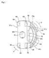
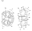
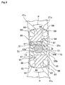
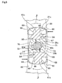
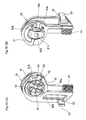
- FIG. 1 to FIG. 6 illustrate a first example of an embodiment of the present invention.
- the tilt steering apparatus of this example basically has: a steering column 6a that is pivotally displaced centered around a tilt shaft (not illustrated) that is provided in the width direction in the front section and that supports a steering shaft 5a on the inside so as to be able to rotate freely; a fixed-side bracket 13 that is made of metal, is supported by the vehicle body and has a pair of support plate portions 34a, 34b that hold the steering column 6a; vertically long holes (long tilt holes) 35a, 35b that extend in the up-down direction and are provided in portions of the support plate portions 34a, 34b that are aligned with each other; an adjustment rod 14 that is inserted in the width direction through the vertically long holes 35a, 35b; an anchor portion 37 that is provided in a portion on the base-end portion of the adjustment rod 14 that protrudes from the outside surface of one of the support plate portions 34a, and that engages with the vertically long hole 35a of the one
- a displacement-side bracket 12 is fastened to the intermediate portion in the axial direction of the steering column 6a, and through holes 32 that pass through in the width direction are formed in portions of part of the displacement-side bracket 12 that are aligned with the vertically long holes 35a, 35b.
- An installation plate portion 33 is provided in the top portion of the fixed-side bracket 13, and the fixed-side bracket 13 is supported by the vehicle body by way of this installation plate portion 33.
- the pair of support plate portions 34a, 34b are formed so as to hang down from the installation plate portion 33 and hold the displacement-side bracket 12 on both sides in the width direction.
- the adjustment rod 14 is also inserted through the through holes 32 in the displacement-side bracket 12
- the cam apparatus 47 has the driven-side cam 15a, and a drive-side cam 16 that is fitted around the tip-end portion of the adjustment rod 14 in a state so as to be able to rotate centered around the adjustment rod 14 and such that displacement toward the tip-end side of the adjustment rod 14 is suppressed, and has a drive-side cam surface 44 provided on the inside surface thereof; and is such that the driven-side cam surface 42 and the drive-side cam surface 44, which are both uneven surfaces in the circumferential direction, engage with each other
- the base-end portion of an adjustment lever 17 that rotates the adjustment rod 14 is joined to the drive-side cam 16.
- the tilt steering apparatus of this example has a buffer member 21c that is formed using a material that is softer than the metal material of the driven-side cam 15a and the metal material of the fixed-side bracket 13 (support plate portions 34a, 34b), and is assembled by fitting and fastening to the convex engaging portion 39c.
- a feature of this example is the shape of the convex engaging portion 39c that is formed on the inside surface of the metal driven-side cam 15a, and the shape of the synthetic resin buffer member 21c that is assembled in the convex engaging portion 39c.
- the construction and functions of the other parts are the same as in a tilt steering apparatus having conventional construction
- the buffer member 21c has a pair of buffer portions 41c that are provided in portions on both the top and bottom sides of a circular hole 40b that is formed in the center portion
- the convex engaging portion 39 fits inside between the pair of buffer portions 41c, and the surfaces on both the top and bottom ends of the convex engaging portion 39c are covered by the buffer portions 41c.
- the surfaces on both the front and rear sides of the convex engaging portion 39c are constructed so as to not protrude further in the forward-backward direction than the surfaces on both the front and rear sides of the buffer portions 41c.
- a pair of protruding hook shaped pieces 51 are provided on both end portions in the width direction in the center portion in the up-down direction of the outside surface of the buffer member 21c.
- the surfaces on both the top and bottom sides of the convex engaging portion 39 and the end surfaces of the buffer portions 41c that face each other, which are opposing surfaces for the top and bottom side surfaces of the convex engaging portion 39, are constructed by crank-shaped stepped surfaces that fit with each other.
- convex portion-side protrusions 64 that protrude in the up-down direction are formed on the rear-end portions of the surfaces on both the top and bottom ends of the convex engaging portion 39c in the direction of tightening of the drive-side cam 16 (direction of arrow ⁇ in FIG. 1 to FIG. 5 ).
- buffer-portion-side protrusions 65 that protrude in the up-down direction are formed on the end surfaces of the buffer portions 41c that face each other in the area from the front-end portion to the center portion in the direction of tightening (direction of arrow ⁇ ).
- the width dimension w in the forward-backward direction of these buffer-portion-side protrusions 65 are slightly larger than two thirds the width dimension W in the forward-backward direction of the end surfaces of the buffer portions 41c that face each other (w > (2/3) W).
- the end surfaces of the buffer portions 41c that face each other become crank shaped stepped surfaces that match with the end surfaces on both the top and bottom of the convex engaging portion 39c.
- the side surfaces 66 of the surfaces on both the front and rear sides of the convex portion-side protrusions 64 on the front side in the direction of tightening come in contact with the side surfaces 67 of the surfaces on both the front and rear sides of the buffer-portion-side protrusions 65 on the rear side in the direction of tightening (direction of arrow ⁇ ).
- the buffer-portion-side protrusions 65 that form crank shaped stepped surfaces that function as stoppers are provided at two locations of the pair of buffer portions 41c that are rotationally symmetric with respect to the center axis of the adjustment rod 14
- low-rigidity portions 68 are provided in the four corners on the top and bottom and front and rear of the buffer member 21c in both the front and rear end portion of the upper half of the buffer portion 41c on the top side, and in both the front and rear end portions of the lower half of the buffer portion 41c on the bottom side.
- the low-rigidity portions 68 By suitably lowering the rigidity of the low-rigidity portions 68 by providing through holes 69, which are portions where the material has been removed, in the inside portions of the low-rigidity portions 68, so as to pass in the axial direction, the low-rigidity portions 68 have an increased shock absorbing function
- both the top and bottom end portions of the surfaces on both the front and rear sides of the buffer member 21c that correspond to the low-rigidity portions 68 protrude slightly further in the forward-backward direction than the intermediate portion in the up-down direction, which corresponds to the remaining portions
- the overall shape of the driven-side cam 15a that includes the convex engaging portion 39c, and the overall shape of the buffer member 21c that includes the buffer portions 41c are formed so as to be rotationally symmetric centered on the center axis of the adjustment rod 14 that is inserted through the circular hole 40b.
- the low rigidity portions 68 Due to this rotation, of the low-rigidity portions 68 that are located in the four corner portions, the low rigidity portions 68 in the two diagonally opposite locations that are located at the front in the same direction (direction of the arrow ⁇ ) (one location at the top left and one location at the bottom right in FIG.
- the convex engaging portion 39c and the buffer member 21c rotate just a minute amount in the same direction (direction opposite the direction of arrow ⁇ or direction of arrow ⁇ ) inside the vertically long hole 35b Due to this rotation, the low-rigidity portions 68 located in diagonally opposite corners are elastically restored
- the buffer portions 41c are in a stiff state between the edges 62, 63 on both the front and rear sides of the vertically long hole 35b, and the portions separated from the convex portion-side protrusions 64 of the surfaces of both the top and bottom ends of the convex engaging portion 39c.
- the rotation force in the tightening direction is transmitted from the convex engaging portion 39c to the buffer portions 41c by way of the side surfaces 66 on the front sides in tightening direction (direction of arrow ⁇ ) of the convex portion-side protrusions 64 and the side surfaces 67 on the rear sides in the tightening direction (direction of arrow ⁇ ) of the buffer-portion-side protrusions 65
- the side surfaces 67 of the buffer-portion-side protrusions 65 face in nearly the forward-backward direction.
- these side surfaces 67 face in a direction that can efficiently support the rotation force (force in the circumferential direction centered around the adjustment rod 14) in the tightening direction (direction of arrow ⁇ ) Therefore, in the state illustrated in FIG. 5 , it is possible to efficiently support the rotation force in the tightening direction (direction of arrow ⁇ ) by the buffer-portion-side protrusions 65
- the width dimension w in the forward-backward direction of these buffer-portion-side protrusions 65 is sufficiently large (w > (2/3) W), so the strength of these buffer-portion-side protrusions 65 is sufficiently maintained. Therefore, it is difficult for the buffer portions 41c that include these buffer-portion-side protrusions 65 to be damaged, and it is possible to improve the durability of the buffer member 21c by an amount due to these buffer-portion-side protrusions 65
- the height position of the steering wheel 1 is maintained by engagement between a female gear 50 and male gear 54.
- the axial force that is generated by the cam apparatus 47 is kept small, it is possible to securely maintain the height position.
- This axial force is sufficient as long as it is large enough that there is no looseness of the displacement-side bracket 12 inside the fixed-side bracket 13. Keeping the axial force generated by the cam apparatus 47 low is related to being able to keep the rotation force in the tightening direction (direction of arrow ⁇ ) that is applied to the driven-side cam 15 low when rotating the drive-side cam 16 in the same direction (direction of arrow ⁇ ) with the adjustment lever 17.
- this rotation force low is related to being able to suppress the rotating force that is transmitted from the convex engaging portion 39c to the buffer member 21c, which leads to make it easier to maintain the durability of the buffer member 21c. Therefore, by combining the construction of this example with a mechanism for maintaining the height position of the steering wheel 1 by the engagement of the female gear 50 and the male gear 54, a sufficient effect can be obtained.
- the axial force that is generated by the cam apparatus 47 can be arbitrarily and easily adjusted by adjusting the tightening torque of the nut 45.
- the convex engaging portion 39c and buffer portions 41c to the convex engaging portion 39a on the base-end side of the adjustment rod 14 and the pair of buffer portions 41a of the buffer member 21a that is attached to that convex engaging portion 39a, however, it is not absolutely necessary to employ the same construction.
- the shape of the pair of vertically long holes 35a, 35b is not limited to a partial arc shape that is centered around the tilt shaft, and the effect of this example can also be obtained in the case where the shape is a simple straight shape.
- the construction illustrated in FIG 14 to FIG. 18 could also be 180 degrees in the opposite direction.
- FIG 7 to FIG. 10 illustrate a second example of an embodiment of the present invention.
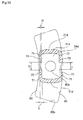
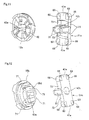
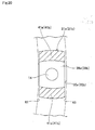
- concave portions 71 are formed in four locations of both the top and bottom end portions of the surfaces on both the front and rear sides of the convex engaging portion 39d, and the width dimension in the forward-backward direction of the convex engaging portion 39d is narrower on both the top and bottom end portions in the up-down direction than the intermediate portion in the up-down direction In other words, the intermediate portions in the up-down direction of both the front and rear sides of the convex engaging portion 39d protrude out slightly more than both end portions in the up-down direction Moreover, buffer portions 41d are formed in positions of the buffer member 21d that surround the circular hole 40b that is formed in the center portion from both the top and bottom sides The space between these buffer portions 41d is equal to or slightly larger than the height in the up-down direction of the convex engaging portion 39d; the convex engaging portion 39d fits inside between the buffer portions 41d; and both the top and bottom end
- flat plate-shaped cover portions 73 that extend in a direction toward each other are provided at a total of four locations on both the front and rear end portions of the surfaces of the buffer portions 41d that face each other.
- the thickness T of these cover portions 73 is slightly greater than the height of stepped portions between the concave portions 71 that are formed on the surfaces on both the front and rear sides of the convex engaging portion 39d and the intermediate portion in the height direction (T > H).
- the space D between the edges of the ends in the up-down direction of the top and bottom cover portions 73 is slightly greater than the length L in the up-down direction of the intermediate portion in the up-down direction of the surfaces on both the front and rear sides of the convex engaging portion 39d (D > L) Therefore, in a state in which the driven-side cam 15b and the buffer member 21d are brought close together from the state illustrated in FIG. 8 and FIG. 9 to a combined state as illustrated in FIG. 7 , the convex engaging portion 39d fits between the buffer portions 41d, and both end portions in the up-down direction on both side surfaces in the forward-backward direction of the convex engaging portion 39d are covered by the cover portions 73.
- cover portions 73 that function as stoppers are provided at four locations in the pair of buffer portions 41d that are rotationally symmetric about the center axis of the adjustment rod 14
- cover portions 73 that function as stoppers at two locations in the pair of buffer portions 41d that are rotationally symmetric about the center axis, or in other words, only on the front sides in the tightening direction (direction of arrow ⁇ ).
- the cover portions 73 do not function as stoppers alone, but working together with the pair of buffer portions 41d and function as stoppers for stopping rotation of the driven-side cam 15b
- cover portions 73 are located between the metal convex engaging portion 39d that is formed on the inside surface of the driven-side cam 15b and the edges 62, 63 on both the front and rear sides of the vertically long hole 35b. Therefore, there is no direct contact between the convex engaging portion 39d and the edges 62, 63 on both the front and rear sides, so unpleasant vibration and noise are not generated due to direct impact between metal members.
- the shape of the convex engaging portion 39d and the buffer member 21d have up-down symmetry, so even though the assembly direction is not regulated, the functions and effects described above can be obtained.
- the amount of wear of the cover portions 73 is kept small Even if these cover portions 73 wear out, it is possible to prevent the driven-side cam 15b from rotating centered around the adjustment rod 14 by the convex engaging portion 39d, so even when used over a long period of time, impairment of smooth adjustment of the up-down position of the steering wheel 1 is prevented.
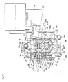
- FIG. 11 and FIG. 12 illustrate a third example of an embodiment of the present invention
- the construction of this example is basically the same as the construction of the second example of an embodiment of the present invention, however, as in the first example of an embodiment of the present invention, low-rigidity portions 68 are provided in the four corner portions on the top and bottom and front and rear of the buffer member 21e by forming through holes 69, which correspond to the portions where material has been removed, in the inside section of both the front and rear end portions of the top hale of the buffer portion 41e on the top side, and both the front and rear end portion of the bottom half of the buffer portion 41e on the bottom side so as to pass through in the axial direction.
- low-rigidity portions 68 are different from the second example of an embodiment of the present invention in that the through holes 69 as the portions where material has been removed is formed so as to pass through in the inside section thereof and that both the top and bottom end portions of the surfaces on both the front and rear sides of the buffer member 21e that correspond to the low-rigidity portions 68 protrude slightly further in the forward-backward direction than the intermediate portions in the up-down direction of the remaining portions
- the construction and functions of the other parts are the same as in the tilt steering apparatus of the first and second examples of an embodiment of the present invention.
- a feature of the present invention is construction that achieves the prevention of the occurrence of unpleasant noise due to an impact in the direction of rotation during height adjustment of the steering wheel between a convex engaging portion that protrudes from the inside surface of the driven-side cam that rotates inside a vertically long hole and the edges on both the front and rear sides of the vertically long hole Therefore, the present invention is constructed with the characteristic elements of the present invention that include: (1) stoppers that prevent the collision between the convex engaging portion and the front-side edge or rear-side edge of the vertically long hole when the driven-side cam is rotated accompanying the expansion or contraction of the axial dimension of the cam apparatus, and that regulate the rotation of the driven-side cam; (2) crank-shaped stepped surfaces that are provided on the convex engaging portion of the driven-side cam and on a pair of buffer portions of a buffer member; (3) cover portions that are provided in part of the buffer member and that cover
- the present invention can be widely applied to the construction of tilt steering apparatuses that have at least a manual tilt mechanism, and can be also applied to tilt and telescopic steering apparatuses that further have a telescopic mechanism for adjusting the forward-backward position of the steering wheel
Landscapes
- Engineering & Computer Science (AREA)
- Chemical & Material Sciences (AREA)
- Combustion & Propulsion (AREA)
- Transportation (AREA)
- Mechanical Engineering (AREA)
- Steering Controls (AREA)
Applications Claiming Priority (4)
| Application Number | Priority Date | Filing Date | Title |
|---|---|---|---|
| JP2012156115A JP5796553B2 (ja) | 2012-07-12 | 2012-07-12 | チルト式ステアリング装置 |
| JP2013041691A JP5692257B2 (ja) | 2013-03-04 | 2013-03-04 | チルト式ステアリング装置 |
| JP2013041692A JP5796589B2 (ja) | 2013-03-04 | 2013-03-04 | チルト式ステアリング装置 |
| PCT/JP2013/068903 WO2014010641A2 (ja) | 2012-07-12 | 2013-07-10 | チルトステアリング装置 |
Publications (3)
| Publication Number | Publication Date |
|---|---|
| EP2873589A2 true EP2873589A2 (de) | 2015-05-20 |
| EP2873589A4 EP2873589A4 (de) | 2017-07-19 |
| EP2873589B1 EP2873589B1 (de) | 2019-03-06 |
Family
ID=49916621
Family Applications (1)
| Application Number | Title | Priority Date | Filing Date |
|---|---|---|---|
| EP13817393.5A Active EP2873589B1 (de) | 2012-07-12 | 2013-07-10 | Neigungslenkvorrichtung |
Country Status (4)
| Country | Link |
|---|---|
| US (1) | US9150241B2 (de) |
| EP (1) | EP2873589B1 (de) |
| CN (3) | CN105416380B (de) |
| WO (1) | WO2014010641A2 (de) |
Families Citing this family (19)
| Publication number | Priority date | Publication date | Assignee | Title |
|---|---|---|---|---|
| GB201310768D0 (en) * | 2013-06-17 | 2013-07-31 | Trw Ltd | A Steering Column Assembly |
| US9764757B2 (en) * | 2014-06-27 | 2017-09-19 | Steering Solutions Ip Holding Corporation | Steering column energy absorbing rake lock |
| US10279833B2 (en) * | 2015-01-13 | 2019-05-07 | Nsk Ltd. | Cam device and position adjustment device for steering wheel |
| FR3035057B1 (fr) * | 2015-04-15 | 2018-07-27 | Zf Systemes De Direction Nacam S.A.S. | Mecanisme de serrage a cames et colonne de direction associee |
| US10780910B2 (en) * | 2016-02-12 | 2020-09-22 | Nsk Americas, Inc. | Self-aligning drive gear |
| CN105711637B (zh) * | 2016-04-07 | 2017-11-28 | 重庆长安汽车股份有限公司 | 一种转向管柱角度调节机构 |
| JP2017198271A (ja) * | 2016-04-27 | 2017-11-02 | 日本電産サンキョー株式会社 | 流体ダンパ装置、ダンパ付き機器および洋式トイレユニット |
| JP6796255B2 (ja) * | 2017-02-10 | 2020-12-09 | 株式会社ジェイテクト | ステアリング装置 |
| US10494012B2 (en) * | 2017-09-22 | 2019-12-03 | Steering Solutions Ip Holding Corporation | Travel control system for cam assembly |
| US10286945B2 (en) * | 2017-10-05 | 2019-05-14 | Thyssenkrupp Ag | Adjustable steering column assembly |
| US10597062B2 (en) | 2017-10-09 | 2020-03-24 | Thyssenkrupp Presta Ag | Steering column assembly with crash bracket rotation dampening mechanism and methods of making and using same |
| CN108482477B (zh) * | 2018-03-08 | 2021-07-23 | 蒂森克虏伯普利斯坦汽车零部件(上海)有限公司 | 汽车转向柱的调节系统 |
| CN108909822B (zh) * | 2018-06-12 | 2020-05-19 | 吉利汽车研究院(宁波)有限公司 | 一种转向管柱组件的锁止装置、转向管柱组件以及车辆 |
| CN108909824B (zh) * | 2018-06-12 | 2020-02-18 | 吉利汽车研究院(宁波)有限公司 | 一种转向管柱降噪结构 |
| DE102018128119A1 (de) * | 2018-11-09 | 2020-05-14 | Trw Automotive Gmbh | Feststelleinrichtung für eine verstellbare Lenksäulenbaugruppe |
| US11186307B2 (en) * | 2019-10-31 | 2021-11-30 | Steering Solutions Ip Holding Corporation | Rake lever assembly |
| US11279393B2 (en) * | 2020-04-29 | 2022-03-22 | Steering Solutions Ip Holding Corporation | Inner cam assembly for steering rake adjustment assembly |
| CN115009348B (zh) * | 2022-07-22 | 2023-10-31 | 奇瑞汽车股份有限公司 | 一种手动四向调节转向管柱结构 |
| CN115465349A (zh) * | 2022-09-30 | 2022-12-13 | 中国第一汽车股份有限公司 | 转向盘及车辆 |
Family Cites Families (18)
| Publication number | Priority date | Publication date | Assignee | Title |
|---|---|---|---|---|
| US5301567A (en) * | 1992-09-23 | 1994-04-12 | Chrysler Corporation | Low pivot tilt steering column clamping mechanism |
| US7021660B2 (en) * | 2002-09-30 | 2006-04-04 | Nsk Steering Systems America, Inc. | Adjustable steering column for motor vehicles |
| JP4304584B2 (ja) * | 2003-06-18 | 2009-07-29 | 株式会社ジェイテクト | チルトヒンジ機構および電動パワーステアリング装置 |
| JP4247996B2 (ja) * | 2005-03-18 | 2009-04-02 | 株式会社山田製作所 | ステアリング装置の固定装置 |
| JP5131425B2 (ja) * | 2005-11-21 | 2013-01-30 | 日本精工株式会社 | ステアリングコラム装置 |
| JP5082612B2 (ja) * | 2007-06-13 | 2012-11-28 | 日本精工株式会社 | ステアリング装置 |
| EP2105369A2 (de) * | 2008-03-25 | 2009-09-30 | NSK Ltd. | Lenkung |
| JP2009227181A (ja) * | 2008-03-25 | 2009-10-08 | Nsk Ltd | ステアリング装置 |
| JP5203792B2 (ja) | 2008-04-18 | 2013-06-05 | 株式会社山田製作所 | チルトステアリング装置 |
| US7819426B2 (en) * | 2008-04-24 | 2010-10-26 | Gm Global Technology Operations, Inc. | Over-center locking mechanism for steering column assembly |
| JP5195202B2 (ja) * | 2008-09-16 | 2013-05-08 | 日本精工株式会社 | ステアリング装置 |
| US8671796B2 (en) * | 2010-07-21 | 2014-03-18 | Nsk Ltd. | Steering device |
| JP5293824B2 (ja) | 2010-08-05 | 2013-09-18 | 日本精工株式会社 | 衝撃吸収式ステアリング装置 |
| JP5293825B2 (ja) * | 2010-08-06 | 2013-09-18 | 日本精工株式会社 | 衝撃吸収式ステアリング装置 |
| JP5229279B2 (ja) | 2010-08-17 | 2013-07-03 | 日本精工株式会社 | 衝撃吸収式ステアリング装置 |
| JP5229280B2 (ja) | 2010-08-19 | 2013-07-03 | 日本精工株式会社 | 衝撃吸収式ステアリング装置 |
| CN102523739B (zh) * | 2010-09-14 | 2013-12-25 | 日本精工株式会社 | 转向装置 |
| CN103370255B (zh) * | 2010-10-08 | 2016-07-06 | Trw操舵系统波兰有限责任公司 | 转向柱组件 |
-
2013
- 2013-07-10 CN CN201510733511.9A patent/CN105416380B/zh active Active
- 2013-07-10 US US14/355,314 patent/US9150241B2/en not_active Expired - Fee Related
- 2013-07-10 WO PCT/JP2013/068903 patent/WO2014010641A2/ja not_active Ceased
- 2013-07-10 CN CN201380003477.9A patent/CN103874617B/zh active Active
- 2013-07-10 EP EP13817393.5A patent/EP2873589B1/de active Active
- 2013-07-10 CN CN201510790563.XA patent/CN105438248B/zh active Active
Non-Patent Citations (1)
| Title |
|---|
| See references of WO2014010641A2 * |
Also Published As
| Publication number | Publication date |
|---|---|
| CN103874617B (zh) | 2016-03-30 |
| CN105416380B (zh) | 2017-09-29 |
| WO2014010641A2 (ja) | 2014-01-16 |
| CN105416380A (zh) | 2016-03-23 |
| WO2014010641A3 (ja) | 2014-03-06 |
| US20140284909A1 (en) | 2014-09-25 |
| EP2873589B1 (de) | 2019-03-06 |
| CN105438248B (zh) | 2018-01-30 |
| CN103874617A (zh) | 2014-06-18 |
| EP2873589A4 (de) | 2017-07-19 |
| US9150241B2 (en) | 2015-10-06 |
| CN105438248A (zh) | 2016-03-30 |
Similar Documents
| Publication | Publication Date | Title |
|---|---|---|
| EP2873589B1 (de) | Neigungslenkvorrichtung | |
| JP6112168B2 (ja) | 電動ステアリングホイールの位置調節装置 | |
| US9550513B2 (en) | Steering column support construction | |
| EP2639135B1 (de) | Lenksäulenhaltevorrichtung | |
| US8919220B2 (en) | Steering column apparatus | |
| JP5050550B2 (ja) | ステアリング装置 | |
| EP2765057B1 (de) | Teleskopische lenkvorrichtung | |
| US20150107398A1 (en) | Telescopic steering apparatus and outer column | |
| US9108672B2 (en) | Steering column apparatus | |
| EP3130525B1 (de) | Vorrichtung zur einstellung einer lenkradposition | |
| EP3225505B1 (de) | Lenkvorrichtung | |
| WO2012053319A1 (ja) | ステアリングコラム用支持装置およびその組立方法 | |
| US9604661B2 (en) | Steering column apparatus | |
| US20190111962A1 (en) | Position adjustment device for steering wheel | |
| CN112930296B (zh) | 转向柱装置 | |
| JP2009154789A (ja) | ステアリングコラム装置 | |
| JP2002104205A (ja) | 車両用ステアリング装置 | |
| JP5796553B2 (ja) | チルト式ステアリング装置 | |
| JP5327203B2 (ja) | ステアリングコラム用支持装置 | |
| JP5327208B2 (ja) | ステアリングコラム用支持装置 | |
| JP5327193B2 (ja) | ステアリングコラム用支持装置 | |
| JP2017001569A (ja) | テレスコピック式ステアリングコラム装置 |
Legal Events
| Date | Code | Title | Description |
|---|---|---|---|
| PUAI | Public reference made under article 153(3) epc to a published international application that has entered the european phase |
Free format text: ORIGINAL CODE: 0009012 |
|
| 17P | Request for examination filed |
Effective date: 20140430 |
|
| AK | Designated contracting states |
Kind code of ref document: A2 Designated state(s): AL AT BE BG CH CY CZ DE DK EE ES FI FR GB GR HR HU IE IS IT LI LT LU LV MC MK MT NL NO PL PT RO RS SE SI SK SM TR |
|
| AX | Request for extension of the european patent |
Extension state: BA ME |
|
| DAX | Request for extension of the european patent (deleted) | ||
| REG | Reference to a national code |
Ref country code: DE Ref legal event code: R079 Ref document number: 602013051963 Country of ref document: DE Free format text: PREVIOUS MAIN CLASS: B62D0001180000 Ipc: B62D0001184000 |
|
| A4 | Supplementary search report drawn up and despatched |
Effective date: 20170621 |
|
| RIC1 | Information provided on ipc code assigned before grant |
Ipc: B62D 1/184 20060101AFI20170614BHEP |
|
| GRAP | Despatch of communication of intention to grant a patent |
Free format text: ORIGINAL CODE: EPIDOSNIGR1 |
|
| STAA | Information on the status of an ep patent application or granted ep patent |
Free format text: STATUS: GRANT OF PATENT IS INTENDED |
|
| INTG | Intention to grant announced |
Effective date: 20180926 |
|
| GRAS | Grant fee paid |
Free format text: ORIGINAL CODE: EPIDOSNIGR3 |
|
| GRAA | (expected) grant |
Free format text: ORIGINAL CODE: 0009210 |
|
| STAA | Information on the status of an ep patent application or granted ep patent |
Free format text: STATUS: THE PATENT HAS BEEN GRANTED |
|
| AK | Designated contracting states |
Kind code of ref document: B1 Designated state(s): AL AT BE BG CH CY CZ DE DK EE ES FI FR GB GR HR HU IE IS IT LI LT LU LV MC MK MT NL NO PL PT RO RS SE SI SK SM TR |
|
| REG | Reference to a national code |
Ref country code: GB Ref legal event code: FG4D |
|
| REG | Reference to a national code |
Ref country code: CH Ref legal event code: EP Ref country code: AT Ref legal event code: REF Ref document number: 1104143 Country of ref document: AT Kind code of ref document: T Effective date: 20190315 |
|
| REG | Reference to a national code |
Ref country code: DE Ref legal event code: R096 Ref document number: 602013051963 Country of ref document: DE |
|
| REG | Reference to a national code |
Ref country code: IE Ref legal event code: FG4D |
|
| REG | Reference to a national code |
Ref country code: NL Ref legal event code: MP Effective date: 20190306 |
|
| REG | Reference to a national code |
Ref country code: LT Ref legal event code: MG4D |
|
| PG25 | Lapsed in a contracting state [announced via postgrant information from national office to epo] |
Ref country code: NO Free format text: LAPSE BECAUSE OF FAILURE TO SUBMIT A TRANSLATION OF THE DESCRIPTION OR TO PAY THE FEE WITHIN THE PRESCRIBED TIME-LIMIT Effective date: 20190606 Ref country code: FI Free format text: LAPSE BECAUSE OF FAILURE TO SUBMIT A TRANSLATION OF THE DESCRIPTION OR TO PAY THE FEE WITHIN THE PRESCRIBED TIME-LIMIT Effective date: 20190306 Ref country code: SE Free format text: LAPSE BECAUSE OF FAILURE TO SUBMIT A TRANSLATION OF THE DESCRIPTION OR TO PAY THE FEE WITHIN THE PRESCRIBED TIME-LIMIT Effective date: 20190306 Ref country code: LT Free format text: LAPSE BECAUSE OF FAILURE TO SUBMIT A TRANSLATION OF THE DESCRIPTION OR TO PAY THE FEE WITHIN THE PRESCRIBED TIME-LIMIT Effective date: 20190306 |
|
| PG25 | Lapsed in a contracting state [announced via postgrant information from national office to epo] |
Ref country code: NL Free format text: LAPSE BECAUSE OF FAILURE TO SUBMIT A TRANSLATION OF THE DESCRIPTION OR TO PAY THE FEE WITHIN THE PRESCRIBED TIME-LIMIT Effective date: 20190306 Ref country code: LV Free format text: LAPSE BECAUSE OF FAILURE TO SUBMIT A TRANSLATION OF THE DESCRIPTION OR TO PAY THE FEE WITHIN THE PRESCRIBED TIME-LIMIT Effective date: 20190306 Ref country code: HR Free format text: LAPSE BECAUSE OF FAILURE TO SUBMIT A TRANSLATION OF THE DESCRIPTION OR TO PAY THE FEE WITHIN THE PRESCRIBED TIME-LIMIT Effective date: 20190306 Ref country code: GR Free format text: LAPSE BECAUSE OF FAILURE TO SUBMIT A TRANSLATION OF THE DESCRIPTION OR TO PAY THE FEE WITHIN THE PRESCRIBED TIME-LIMIT Effective date: 20190607 Ref country code: BG Free format text: LAPSE BECAUSE OF FAILURE TO SUBMIT A TRANSLATION OF THE DESCRIPTION OR TO PAY THE FEE WITHIN THE PRESCRIBED TIME-LIMIT Effective date: 20190606 Ref country code: RS Free format text: LAPSE BECAUSE OF FAILURE TO SUBMIT A TRANSLATION OF THE DESCRIPTION OR TO PAY THE FEE WITHIN THE PRESCRIBED TIME-LIMIT Effective date: 20190306 |
|
| PGFP | Annual fee paid to national office [announced via postgrant information from national office to epo] |
Ref country code: FR Payment date: 20190619 Year of fee payment: 7 |
|
| REG | Reference to a national code |
Ref country code: AT Ref legal event code: MK05 Ref document number: 1104143 Country of ref document: AT Kind code of ref document: T Effective date: 20190306 |
|
| PG25 | Lapsed in a contracting state [announced via postgrant information from national office to epo] |
Ref country code: IT Free format text: LAPSE BECAUSE OF FAILURE TO SUBMIT A TRANSLATION OF THE DESCRIPTION OR TO PAY THE FEE WITHIN THE PRESCRIBED TIME-LIMIT Effective date: 20190306 Ref country code: EE Free format text: LAPSE BECAUSE OF FAILURE TO SUBMIT A TRANSLATION OF THE DESCRIPTION OR TO PAY THE FEE WITHIN THE PRESCRIBED TIME-LIMIT Effective date: 20190306 Ref country code: RO Free format text: LAPSE BECAUSE OF FAILURE TO SUBMIT A TRANSLATION OF THE DESCRIPTION OR TO PAY THE FEE WITHIN THE PRESCRIBED TIME-LIMIT Effective date: 20190306 Ref country code: AL Free format text: LAPSE BECAUSE OF FAILURE TO SUBMIT A TRANSLATION OF THE DESCRIPTION OR TO PAY THE FEE WITHIN THE PRESCRIBED TIME-LIMIT Effective date: 20190306 Ref country code: CZ Free format text: LAPSE BECAUSE OF FAILURE TO SUBMIT A TRANSLATION OF THE DESCRIPTION OR TO PAY THE FEE WITHIN THE PRESCRIBED TIME-LIMIT Effective date: 20190306 Ref country code: ES Free format text: LAPSE BECAUSE OF FAILURE TO SUBMIT A TRANSLATION OF THE DESCRIPTION OR TO PAY THE FEE WITHIN THE PRESCRIBED TIME-LIMIT Effective date: 20190306 Ref country code: SK Free format text: LAPSE BECAUSE OF FAILURE TO SUBMIT A TRANSLATION OF THE DESCRIPTION OR TO PAY THE FEE WITHIN THE PRESCRIBED TIME-LIMIT Effective date: 20190306 Ref country code: PT Free format text: LAPSE BECAUSE OF FAILURE TO SUBMIT A TRANSLATION OF THE DESCRIPTION OR TO PAY THE FEE WITHIN THE PRESCRIBED TIME-LIMIT Effective date: 20190706 |
|
| PG25 | Lapsed in a contracting state [announced via postgrant information from national office to epo] |
Ref country code: SM Free format text: LAPSE BECAUSE OF FAILURE TO SUBMIT A TRANSLATION OF THE DESCRIPTION OR TO PAY THE FEE WITHIN THE PRESCRIBED TIME-LIMIT Effective date: 20190306 Ref country code: PL Free format text: LAPSE BECAUSE OF FAILURE TO SUBMIT A TRANSLATION OF THE DESCRIPTION OR TO PAY THE FEE WITHIN THE PRESCRIBED TIME-LIMIT Effective date: 20190306 |
|
| REG | Reference to a national code |
Ref country code: DE Ref legal event code: R097 Ref document number: 602013051963 Country of ref document: DE |
|
| PG25 | Lapsed in a contracting state [announced via postgrant information from national office to epo] |
Ref country code: AT Free format text: LAPSE BECAUSE OF FAILURE TO SUBMIT A TRANSLATION OF THE DESCRIPTION OR TO PAY THE FEE WITHIN THE PRESCRIBED TIME-LIMIT Effective date: 20190306 Ref country code: IS Free format text: LAPSE BECAUSE OF FAILURE TO SUBMIT A TRANSLATION OF THE DESCRIPTION OR TO PAY THE FEE WITHIN THE PRESCRIBED TIME-LIMIT Effective date: 20190706 |
|
| PGFP | Annual fee paid to national office [announced via postgrant information from national office to epo] |
Ref country code: GB Payment date: 20190710 Year of fee payment: 7 |
|
| PLBE | No opposition filed within time limit |
Free format text: ORIGINAL CODE: 0009261 |
|
| STAA | Information on the status of an ep patent application or granted ep patent |
Free format text: STATUS: NO OPPOSITION FILED WITHIN TIME LIMIT |
|
| PG25 | Lapsed in a contracting state [announced via postgrant information from national office to epo] |
Ref country code: DK Free format text: LAPSE BECAUSE OF FAILURE TO SUBMIT A TRANSLATION OF THE DESCRIPTION OR TO PAY THE FEE WITHIN THE PRESCRIBED TIME-LIMIT Effective date: 20190306 |
|
| 26N | No opposition filed |
Effective date: 20191209 |
|
| PG25 | Lapsed in a contracting state [announced via postgrant information from national office to epo] |
Ref country code: SI Free format text: LAPSE BECAUSE OF FAILURE TO SUBMIT A TRANSLATION OF THE DESCRIPTION OR TO PAY THE FEE WITHIN THE PRESCRIBED TIME-LIMIT Effective date: 20190306 Ref country code: MC Free format text: LAPSE BECAUSE OF FAILURE TO SUBMIT A TRANSLATION OF THE DESCRIPTION OR TO PAY THE FEE WITHIN THE PRESCRIBED TIME-LIMIT Effective date: 20190306 |
|
| REG | Reference to a national code |
Ref country code: CH Ref legal event code: PL |
|
| PG25 | Lapsed in a contracting state [announced via postgrant information from national office to epo] |
Ref country code: TR Free format text: LAPSE BECAUSE OF FAILURE TO SUBMIT A TRANSLATION OF THE DESCRIPTION OR TO PAY THE FEE WITHIN THE PRESCRIBED TIME-LIMIT Effective date: 20190306 |
|
| REG | Reference to a national code |
Ref country code: BE Ref legal event code: MM Effective date: 20190731 |
|
| PG25 | Lapsed in a contracting state [announced via postgrant information from national office to epo] |
Ref country code: CH Free format text: LAPSE BECAUSE OF NON-PAYMENT OF DUE FEES Effective date: 20190731 Ref country code: LI Free format text: LAPSE BECAUSE OF NON-PAYMENT OF DUE FEES Effective date: 20190731 Ref country code: BE Free format text: LAPSE BECAUSE OF NON-PAYMENT OF DUE FEES Effective date: 20190731 Ref country code: LU Free format text: LAPSE BECAUSE OF NON-PAYMENT OF DUE FEES Effective date: 20190710 |
|
| PG25 | Lapsed in a contracting state [announced via postgrant information from national office to epo] |
Ref country code: IE Free format text: LAPSE BECAUSE OF NON-PAYMENT OF DUE FEES Effective date: 20190710 |
|
| GBPC | Gb: european patent ceased through non-payment of renewal fee |
Effective date: 20200710 |
|
| PG25 | Lapsed in a contracting state [announced via postgrant information from national office to epo] |
Ref country code: FR Free format text: LAPSE BECAUSE OF NON-PAYMENT OF DUE FEES Effective date: 20200731 Ref country code: GB Free format text: LAPSE BECAUSE OF NON-PAYMENT OF DUE FEES Effective date: 20200710 |
|
| PG25 | Lapsed in a contracting state [announced via postgrant information from national office to epo] |
Ref country code: CY Free format text: LAPSE BECAUSE OF FAILURE TO SUBMIT A TRANSLATION OF THE DESCRIPTION OR TO PAY THE FEE WITHIN THE PRESCRIBED TIME-LIMIT Effective date: 20190306 |
|
| PG25 | Lapsed in a contracting state [announced via postgrant information from national office to epo] |
Ref country code: MT Free format text: LAPSE BECAUSE OF FAILURE TO SUBMIT A TRANSLATION OF THE DESCRIPTION OR TO PAY THE FEE WITHIN THE PRESCRIBED TIME-LIMIT Effective date: 20190306 Ref country code: HU Free format text: LAPSE BECAUSE OF FAILURE TO SUBMIT A TRANSLATION OF THE DESCRIPTION OR TO PAY THE FEE WITHIN THE PRESCRIBED TIME-LIMIT; INVALID AB INITIO Effective date: 20130710 |
|
| PG25 | Lapsed in a contracting state [announced via postgrant information from national office to epo] |
Ref country code: MK Free format text: LAPSE BECAUSE OF FAILURE TO SUBMIT A TRANSLATION OF THE DESCRIPTION OR TO PAY THE FEE WITHIN THE PRESCRIBED TIME-LIMIT Effective date: 20190306 |
|
| PGFP | Annual fee paid to national office [announced via postgrant information from national office to epo] |
Ref country code: DE Payment date: 20250528 Year of fee payment: 13 |