EP2871984B2 - Electronic vapour provision device - Google Patents
Electronic vapour provision device Download PDFInfo
- Publication number
- EP2871984B2 EP2871984B2 EP13736600.1A EP13736600A EP2871984B2 EP 2871984 B2 EP2871984 B2 EP 2871984B2 EP 13736600 A EP13736600 A EP 13736600A EP 2871984 B2 EP2871984 B2 EP 2871984B2
- Authority
- EP
- European Patent Office
- Prior art keywords
- heating element
- coil
- liquid
- support
- provision device
- Prior art date
- Legal status (The legal status is an assumption and is not a legal conclusion. Google has not performed a legal analysis and makes no representation as to the accuracy of the status listed.)
- Active
Links
- 238000010438 heat treatment Methods 0.000 claims description 177
- 239000007788 liquid Substances 0.000 claims description 138
- 239000011148 porous material Substances 0.000 claims description 51
- 238000009834 vaporization Methods 0.000 claims description 40
- 239000003571 electronic cigarette Substances 0.000 claims description 24
- 229910010293 ceramic material Inorganic materials 0.000 claims description 4
- 239000006260 foam Substances 0.000 description 8
- SNICXCGAKADSCV-JTQLQIEISA-N (-)-Nicotine Chemical compound CN1CCC[C@H]1C1=CC=CN=C1 SNICXCGAKADSCV-JTQLQIEISA-N 0.000 description 6
- 229960002715 nicotine Drugs 0.000 description 6
- SNICXCGAKADSCV-UHFFFAOYSA-N nicotine Natural products CN1CCCC1C1=CC=CN=C1 SNICXCGAKADSCV-UHFFFAOYSA-N 0.000 description 6
- 230000009471 action Effects 0.000 description 5
- PXHVJJICTQNCMI-UHFFFAOYSA-N Nickel Chemical compound [Ni] PXHVJJICTQNCMI-UHFFFAOYSA-N 0.000 description 4
- 230000014759 maintenance of location Effects 0.000 description 4
- 239000000463 material Substances 0.000 description 4
- 229920003023 plastic Polymers 0.000 description 4
- 239000004033 plastic Substances 0.000 description 4
- 239000007787 solid Substances 0.000 description 4
- 239000011800 void material Substances 0.000 description 4
- DNIAPMSPPWPWGF-UHFFFAOYSA-N Propylene glycol Chemical compound CC(O)CO DNIAPMSPPWPWGF-UHFFFAOYSA-N 0.000 description 3
- 238000004519 manufacturing process Methods 0.000 description 3
- 229920006395 saturated elastomer Polymers 0.000 description 3
- PEDCQBHIVMGVHV-UHFFFAOYSA-N Glycerine Chemical compound OCC(O)CO PEDCQBHIVMGVHV-UHFFFAOYSA-N 0.000 description 2
- WHXSMMKQMYFTQS-UHFFFAOYSA-N Lithium Chemical compound [Li] WHXSMMKQMYFTQS-UHFFFAOYSA-N 0.000 description 2
- 239000000443 aerosol Substances 0.000 description 2
- 235000019504 cigarettes Nutrition 0.000 description 2
- 238000001514 detection method Methods 0.000 description 2
- 230000000694 effects Effects 0.000 description 2
- 229910052744 lithium Inorganic materials 0.000 description 2
- 238000012423 maintenance Methods 0.000 description 2
- 230000004048 modification Effects 0.000 description 2
- 238000012986 modification Methods 0.000 description 2
- 229910001120 nichrome Inorganic materials 0.000 description 2
- 229910052759 nickel Inorganic materials 0.000 description 2
- 230000004044 response Effects 0.000 description 2
- 230000000717 retained effect Effects 0.000 description 2
- 239000000725 suspension Substances 0.000 description 2
- 229910000838 Al alloy Inorganic materials 0.000 description 1
- 239000004411 aluminium Substances 0.000 description 1
- XAGFODPZIPBFFR-UHFFFAOYSA-N aluminium Chemical compound [Al] XAGFODPZIPBFFR-UHFFFAOYSA-N 0.000 description 1
- 229910052782 aluminium Inorganic materials 0.000 description 1
- 230000005540 biological transmission Effects 0.000 description 1
- 239000000919 ceramic Substances 0.000 description 1
- 235000011187 glycerol Nutrition 0.000 description 1
- 239000002689 soil Substances 0.000 description 1
- 239000008259 solid foam Substances 0.000 description 1
Images


Classifications
-
- A—HUMAN NECESSITIES
- A24—TOBACCO; CIGARS; CIGARETTES; SIMULATED SMOKING DEVICES; SMOKERS' REQUISITES
- A24F—SMOKERS' REQUISITES; MATCH BOXES; SIMULATED SMOKING DEVICES
- A24F40/00—Electrically operated smoking devices; Component parts thereof; Manufacture thereof; Maintenance or testing thereof; Charging means specially adapted therefor
- A24F40/40—Constructional details, e.g. connection of cartridges and battery parts
- A24F40/42—Cartridges or containers for inhalable precursors
-
- A—HUMAN NECESSITIES
- A24—TOBACCO; CIGARS; CIGARETTES; SIMULATED SMOKING DEVICES; SMOKERS' REQUISITES
- A24F—SMOKERS' REQUISITES; MATCH BOXES; SIMULATED SMOKING DEVICES
- A24F40/00—Electrically operated smoking devices; Component parts thereof; Manufacture thereof; Maintenance or testing thereof; Charging means specially adapted therefor
- A24F40/40—Constructional details, e.g. connection of cartridges and battery parts
- A24F40/46—Shape or structure of electric heating means
-
- A—HUMAN NECESSITIES
- A24—TOBACCO; CIGARS; CIGARETTES; SIMULATED SMOKING DEVICES; SMOKERS' REQUISITES
- A24F—SMOKERS' REQUISITES; MATCH BOXES; SIMULATED SMOKING DEVICES
- A24F40/00—Electrically operated smoking devices; Component parts thereof; Manufacture thereof; Maintenance or testing thereof; Charging means specially adapted therefor
- A24F40/40—Constructional details, e.g. connection of cartridges and battery parts
- A24F40/44—Wicks
-
- A—HUMAN NECESSITIES
- A24—TOBACCO; CIGARS; CIGARETTES; SIMULATED SMOKING DEVICES; SMOKERS' REQUISITES
- A24F—SMOKERS' REQUISITES; MATCH BOXES; SIMULATED SMOKING DEVICES
- A24F40/00—Electrically operated smoking devices; Component parts thereof; Manufacture thereof; Maintenance or testing thereof; Charging means specially adapted therefor
- A24F40/40—Constructional details, e.g. connection of cartridges and battery parts
- A24F40/48—Fluid transfer means, e.g. pumps
- A24F40/485—Valves; Apertures
-
- A—HUMAN NECESSITIES
- A24—TOBACCO; CIGARS; CIGARETTES; SIMULATED SMOKING DEVICES; SMOKERS' REQUISITES
- A24F—SMOKERS' REQUISITES; MATCH BOXES; SIMULATED SMOKING DEVICES
- A24F7/00—Mouthpieces for pipes; Mouthpieces for cigar or cigarette holders
-
- A—HUMAN NECESSITIES
- A24—TOBACCO; CIGARS; CIGARETTES; SIMULATED SMOKING DEVICES; SMOKERS' REQUISITES
- A24F—SMOKERS' REQUISITES; MATCH BOXES; SIMULATED SMOKING DEVICES
- A24F40/00—Electrically operated smoking devices; Component parts thereof; Manufacture thereof; Maintenance or testing thereof; Charging means specially adapted therefor
- A24F40/10—Devices using liquid inhalable precursors
Definitions
- the specification relates to electronic vapour provision devices.
- Electronic vapour provision devices are typically cigarette-sized and typically function by allowing a user to inhale a nicotine vapour from a liquid store by applying a suction force to a mouthpiece. Some electronic vapour provision devices have an airflow sensor that activates when a user applies the suction force and causes a heater soil to heat up and vaporise the liquid. Electronic vapour provision devices include electronic cigarettes.
- An electronic vapour provision device is known from EP 2 404 515 A1 .
- the present invention provides an electronic vapour provision device comprising a power cell, a vaporiser and a liquid store, where the vaporiser comprises a heating element and a heating element support, wherein the liquid store comprises a porous material, and wherein the heating element support is or forms part of the liquid store, and wherein the porous material comprises smaller pores in the region next to the heating element and larger pores further from the heating element.
- the heating element may be supported from its outside by the heating element support or the heating element support may be supported from its inside by the heating element support.
- One or more gaps may be provided between the heating element and heating element support.
- a vaporiser for use in the electronic vapour provision device comprising a heating element and a porous heating element support, wherein the heating element is a liquid store.
- the present invention also provides a mouthpiece section for an electronic vapour provision device according to any preceding claim, the mouthpiece section including a vaporiser and a liquid store, the vaporiser comprising a heating element and a heating element support, wherein the liquid store comprises a porous material, and wherein the heating element support is or forms part of the liquid store, and wherein the porous material comprises smaller pores in the region next to the heating element and larger pores further from the heating element.
- an electronic vapour provision device comprising a heating element for vaporising liquid; an air outlet for vaporised liquid from the heating element; and a porous heating element support, wherein the heating element support is a store of liquid.
- the electronic vapour provision device may include a power cell for powering the heating element.
- an electronic vapour provision device comprising a power cell, a vaporiser and a liquid store, where the vaporiser comprises a heating element and a heating element support, wherein the liquid store comprises a porous material.
- the electronic vapour provision device may be an electronic cigarette.
- the liquid store may comprise a solid porous material or a rigid porous material.
- the liquid store may comprise a porous ceramic material.
- a solid porous material is advantageous since it is not open to deformation so the properties can be set and maintained.
- the shape can be defined at the manufacturing stage and this specific shape can be retained in the device to give consistency in device usage.
- the liquid store may not comprise an outer liquid store container. Providing a solid porous material removes the need for an outer liquid store container and therefore gives a more efficient storage means.
- the porous material may be optimized for liquid retention and wicking and/or for liquid glycerine retention and wicking. Moreover, the porous material may have pores of substantially equal size. The porous material may comprise pores distributed evenly throughout the material. Moreover, the porous material may be configured such that the majority of the material volume comprises open pores for liquid storage. The liquid store may be sealed on at least part of an outer surface region to inhibit porosity in that region.
- the porous material has smaller pores in a region next to the heating element and larger pores further from the heating element.
- the porous material may have a gradient of pore sizes ranging from smaller pores next to the heating element to larger pores further from the heating element.
- the liquid store may be configured to wick liquid onto the heating element.
- the configuration of pores acts to determine the wicking effect of the storage medium, such that a more efficient means of transmission of liquid onto the heating element can be achieved.
- the heating element support may form part of the liquid store, a separate additional liquid store or the entirety of the liquid store.
- the heating element may be supported from its outside by the heating element support. Alternatively or additionally, the heating element may be supported from its inside by the heating element support.
- One or more gaps may be provided between the heating element and the heating element support. Providing a gap between the heating element and the heating element support allows liquid to be gathered and stored in the gap region for vaporisation. The gap can also act to wick liquid onto the heating element. Also, providing a gap between the heating element and support means that a greater surface area of the heating element is exposed thereby giving a greater surface area for heating and vaporisation.
- the heating element may be a heating coil, such as a wire coil.
- the heating coil may be coiled so as to be supported along its length by the heating element support.
- the turns of the heating coil may be supported by the heating element support.
- the turns of the heating coil may be in contact with the heating element support.
- One or more gaps may be provided between the heating coil and the heating element support.
- the vaporiser may further comprise a vaporisation cavity such that, in use, the vaporisation cavity is a negative pressure cavity. At least part of the heating element may be inside the vaporisation cavity.
- the electronic vapour provision device may comprise a mouthpiece section and the vaporiser may form part of the mouthpiece section.
- the liquid store may form part of the mouthpiece section.
- the liquid store may substantially fill the mouthpiece section.
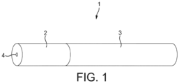
- FIG. 1 there is shown an embodiment of the electronic vapour provision device 1 in the form of an electronic cigarette 1 comprising a mouthpiece 2 and a body 3.
- the electronic cigarette 1 is shaped like a conventional cigarette having a cylindrical shape.
- the mouthpiece 2 has an air outlet 4 and the electronic cigarette 1 is operated when a user places the mouthpiece 2 of the electronic cigarette 1 in their mouth and inhales, drawing air through the air outlet 4.
- Both the mouthpiece 2 and body 3 are cylindrical and are configured to connect to each other coaxially so as to form the conventional cigarette shape.
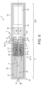
- FIGs 2 shows an example of the electronic cigarette 1 of Figure 1 .
- the body 3 comprises two detachable parts, comprising a battery assembly 5 part and a vaporiser 6 part, and the mouthpiece 2 comprises a liquid store 7.
- the electronic cigarette 1 is shown in its assembled state, wherein the detachable parts 2, 5, 6 are connected in the following order: mouthpiece 2, vaporiser 6, battery assembly 5. Liquid wicks from the liquid store 7 to the vaporiser 6.
- the battery assembly 5 provides electrical power to the vaporiser 6 via mutual electrical contacts of the battery assembly 5 and the vaporiser 6.
- the vaporiser 6 vaporises the wicked liquid and the vapour passes out of the air outlet 4.
- the liquid may for example comprise a nicotine solution.
- the battery assembly 5 comprises a battery assembly casing 8, a power cell 9, electrical contacts 10 and a control circuit 11.
- the battery assembly casing 8 comprises a hollow cylinder which is open at a first end 12.
- the battery assembly casing 8 may be plastic.
- the electrical contacts 10 are located at the first end 12 of the casing 8, and the power cell 9 and control circuit 11 are located within the hollow of the casing 8.
- the power cell 9 may for example be a Lithium Cell.
- the control circuit 11 includes an air pressure sensor 13 and a controller 14 and is powered by the power cell 9.
- the controller 14 is configured to interface with the air pressure sensor 13 and to control provision of electrical power from the power cell 9 to the vaporiser 6.
- the vaporiser 6 comprises a vaporiser casing 15, electrical contacts 16, a heating element 17, a wicking element 18, a vaporisation cavity 19 and a heating element support 20.
- the vaporiser casing 15 comprises a hollow cylinder which is open at both ends with an air inlet 21.
- the vaporiser casing 15 may be formed of an aluminium alloy.
- the air inlet 21 comprises a hole in the vaporiser casing 15 at a first end 22 of the vaporiser casing 15.
- the electrical contacts 16 are located at the first end 22 of the vaporiser casing 15.
- the first end 22 of the vaporiser casing 15 is releasably connected to the first end 12 of the battery assembly casing 8, such that the electrical contacts 16 of the vaporiser are electrically connected to the electrical contacts 10 of the battery assembly.
- the device 1 may be configured such that the vaporiser casing 15 connects to the battery assembly casing 8 by a threaded connection.
- the heating element 17 is formed of a single wire and comprises a heating element coil 23 and two leads 24, as is illustrated in Figures 4 and 5 .
- the heating element may be formed of Nichrome.
- the coil 23 comprises a section of the wire where the wire is formed into a helix about an axis A. At either end of the coil 23, the wire departs from its helical form to provide the leads 24.
- the leads 24 are connected to the electrical contacts 16 and are thereby configured to route electrical power, provided by the power cell 9, to the coil 23.
- the wire of the coil 23 is approximately 0.12 mm in diameter.
- the coil is approximately 25 mm in length, has an internal diameter of approximately 1 mm and a helix pitch of approximately 420 micrometers.
- the void between the successive turns of the coil 23 is therefore approximately 300 micrometers.
- the heating element 17 is located towards the second end 25 of the vaporiser casing 15 and is orientated such that the axis A of the coil 23 is perpendicular to the cylindrical axis B of the vaporiser casing 15. The coil 23 of the heating element 17 is thus perpendicular to the longitudinal axis C of the electronic cigarette 1.
- the wicking element 18 extends from the vaporiser casing 15 into contact with the liquid store 7 of the mouthpiece 2.
- the wicking element 18 is configured to wick liquid in the direction W from the liquid store 7 of the mouthpiece 2 to the heating element 17.
- the wick 18 comprises an arc of porous material extending from a first end of the coil 23, out past the second end 25 of the vaporiser casing 14 and back to a second end of the coil.
- the porous material may be nickel foam, wherein the porosity of the foam is such that the described wicking occurs.
- the vaporisation cavity 19 comprises a region within the hollow of the vaporiser casing 15 in which liquid is vaporised.
- the heating element 17, heating element support 20 and portions 26 of the wicking element 18 are situated within the vaporisation cavity 19.
- the heating element support 20 is configured to support the heating element 17 and to facilitate vaporisation of liquid by the heating element 17.
- the heating element support 20 is an inner support and is illustrated in Figures 3, 4 and 5 .
- the support 20 comprises a rigid cylinder of porous ceramic material.
- the porous ceramic material is shown to have pores 20a distributes throughout the material.
- the support 20 is situated coaxially within the helix of the heating element coil 23 and is slightly longer than the coil 23, such that the ends of the support 20 protrude from the ends of the coil 23.
- the diameter of the cylindrical support 20 is similar to the inner diameter of the helix. As a result, the wire of the coil 23 is substantially in contact with the support 20 and is thereby supported, facilitating maintenance of the shape of the coil 23.
- the heating element coil 23 is thus coiled, or wrapped, around the heating element support 20.
- the solidity provides a stable and secure structure to hold the coil 23 in place.
- the combination of the support 20 and the coil 23 of the heating element 17 provides a heating rod 27, as illustrated in Figures 4 and 5 .
- the heating rod is later described in more detail with reference to Figures 4 and 5 .
- the surface 28 of the support 20 provides a route for liquid from the wick element 18 to wick onto and along, improving the provision of liquid to the vicinity of the heating element 17 for vaporisation.
- the surface 28 of the support 20 also provides surface area for exposing wicked liquid to the heat of the heating element 17.
- the porosity of the support allows liquid to be stored in the heating element support 20. The support is thus a further liquid store.
- the mouthpiece 2 comprises a mouthpiece casing 29.
- the mouthpiece casing 29 comprises a hollow cylinder which is open at a first end 30, with the air outlet 4 comprising a hole in the second end 31 of the casing.
- the mouthpiece casing may be formed of plastic.
- the liquid store 7 is situated within the hollow of the mouthpiece casing 29.
- the liquid store may comprise foam, wherein the foam is substantially saturated in the liquid intended for vaporisation.
- the cross-sectional area of the liquid store 7 is less than that of the hollow of the mouthpiece casing so as to form an air passageway 32 between the first end 30 of the mouthpiece casing 2 and the air outlet 4.
- the first end 30 of the mouthpiece casing 29 is releasably connected to the second end 25 of the vaporiser casing 15, such that the liquid store 7 is in contact with a portion 33 of the wicking element 18 which protrudes from the vaporiser 6.
- Liquid from the liquid store 7 is absorbed by the wicking element 18 and wicks along route W throughout the wicking element 18. Liquid then wicks from the wicking element 18 onto and along the coil 23 of the heating element 17, and onto and along the support 20.
- a user sucks on the second end 31 of the mouthpiece 2. This causes a drop in the air pressure throughout the inner cavity 34 of the electronic cigarette 1, particularly at the air outlet 4.
- the pressure drop within the inner cavity 34 is detected by the pressure sensor 13.
- the controller 14 triggers the provision of power from the power cell 9 to the heating element 17 via the electrical contacts 10, 16.
- the coil of the heating element 17 therefore heats up. Once the coil 17 heats up, liquid in the vaporisation cavity 19 is vaporised.
- liquid on the heating element 17 is vaporised, liquid on the heating element support 20 is vaporised and liquid in portions 26 of the wicking element 18 which are in the immediate vicinity of the heating element 17 may be vaporised.
- the pressure drop within the inner cavity 34 also causes air from outside of the electronic cigarette 1 to be drawn, along route F, through the inner cavity from the air inlet 21 to the air outlet 4. As air is drawn along route F, it passes through the vaporisation cavity 19 and the air passageway 32. The vaporised liquid is therefore conveyed by the air movement along the air passageway 32 and out of the air outlet 4 to be inhaled by the user. In passing through the vaporisation cavity, along route F, the air moves over the heating element 17 in a direction substantially perpendicular to the axis A of the coil 23.
- the air containing the vaporised liquid As the air containing the vaporised liquid is conveyed to the air outlet 4, some of the vapour may condense, producing a fine suspension of liquid droplets in the airflow. Moreover, movement of air through the vaporiser 6 as the user sucks on the mouthpiece 2 can lift fine droplets of liquid off of the wicking element 18, the heating element 17 and/or the heating element support 20. The air passing out of the outlet may therefore comprise an aerosol of fine liquid droplets as well as vaporised liquid.
- the pressure drop within the vaporisation cavity 19 also encourages further wicking of liquid from the liquid store 7, along the wicking element 18, to the vaporisation cavity 19.
- FIG 6 shows a further example of the electronic cigarette 1 of Figure 1 .
- the body 3 is referred to herein as a battery assembly 50
- the mouthpiece 2 includes a liquid store 51 and a vaporiser 52.
- the electronic cigarette 1 is shown in its assembled state, wherein the detachable parts 2, 3 are connected. Liquid wicks from the liquid store 51 to the vaporiser 52.
- the battery assembly 50 provides electrical power to the vaporiser 52 via mutual electrical contacts of the battery assembly 50 and the mouthpiece 2.
- the vaporiser 52 vaporises the wicked liquid and the vapour passes out of the air outlet 4.
- the liquid may for example comprise a nicotine solution.
- the battery assembly 50 comprises a battery assembly casing 53, a power cell 54, electrical contacts 55 and a control circuit 56.
- the battery assembly casing 53 comprises a hollow cylinder which is open at a first end 57.
- the battery assembly casing 53 may be plastic.
- the electrical contacts 55 are located at the first end 57 of the casing 53, and the power cell 54 and control circuit 56 are located within the hollow of the casing 53.
- the power cell 54 may for example be a Lithium Cell.
- the control circuit 56 includes an air pressure sensor 58 and a controller 59 and is powered by the power cell 54.
- the controller 59 is configured to interface with the air pressure sensor 58 and to control provision of electrical power from the power cell 54 to the vaporiser 52, via the electrical contacts 55.
- the mouthpiece 2 further includes a mouthpiece casing 60 and electrical contacts 61.
- the mouthpiece casing 60 comprises a hollow cylinder which is open at a first end 62, with the air outlet 4 comprising a hole in the second end 63 of the casing 60.
- the mouthpiece casing 60 also comprises an air inlet 64, comprising a hole near the first end 62 of the casing 60.
- the mouthpiece casing may be formed of aluminium.
- the electrical contacts 61 are located at the first end of the casing 60. Moreover, the first end 62 of the mouthpiece casing 60 is releasably connected to the first end 57 of the battery assembly casing 53, such that the electrical contacts 61 of the mouthpiece 2 are electrically connected to the electrical contacts 55 of the battery assembly 50.
- the device 1 may be configured such that the mouthpiece casing 60 connects to the battery assembly casing 53 by a threaded connection.
- the liquid store 51 is situated within the hollow mouthpiece casing 60 towards the second end 63 of the casing 60.
- the liquid store 51 comprises a cylindrical tube of porous material saturated in liquid.
- the outer circumference of the liquid store 51 matches the inner circumference of the mouthpiece casing 60.
- the hollow of the liquid store 51 provides an air passageway 65.
- the porous material of the liquid store 51 may comprise foam, wherein the foam is substantially saturated in the liquid intended for vaporisation.
- the vaporiser 52 comprises a vaporisation cavity 66, a heating element support 67 and a heating element 68.
- the vaporisation cavity 66 comprises a region within the hollow of the mouthpiece casing 60 in which liquid is vaporised.
- the heating element 68 and a portion 69 of the support 67 are situated within the vaporisation cavity 66.
- the heating element support 67 is configured to support the heating element 68 from the outside and to facilitate vaporisation of liquid by the heating element 68 and is illustrated in Figures 7 to 9 . Because the support 67 is located outside of the heating element 68, its size is not restricted by the size of the heating element, and so can be much larger than those of the embodiments described above. This facilitates the storing of more liquid by the porous heating element support 67 than those of the embodiments described above.
- the support 67 comprises a hollow cylinder of rigid, porous material and is situated within the mouthpiece casing 60, towards the first end 62 of the casing 60, such that it abuts the liquid store 51.
- the porous material has pores 67a distributes throughout.
- the outer circumference of the support 67 matches the inner circumference of the mouthpiece casing 60.
- the hollow of the support comprises a longitudinal, central channel 70 through the length of the support 67.
- the channel 70 has a square cross-sectional shape, the cross-section being perpendicular to the longitudinal axis of the support.
- the support 67 acts as a wicking element, as it is configured to wick liquid in the direction W from the liquid store 51 of the mouthpiece 2 to the heating element 68.
- the porous material of the support 67 may be nickel foam, wherein the porosity of the foam is such that the described wicking occurs. Once liquid wicks W from the liquid store 51 to the support 67, it is stored in the porous material of the support 67.
- the support 67 is an extension of the liquid store 51.
- the heating element 68 is formed of a single wire and comprises a heating element coil 71 and two leads 72, as is illustrated in Figures 8 and 9 .
- the heating element 68 may be formed of Nichrome.
- the coil 71 comprises a section of the wire where the wire is formed into a helix about an axis A. At either end of the coil 71, the wire departs from its helical form to provide the leads 72.
- the leads 72 are connected to the electrical contacts 61 and are thereby configured to route electrical power, provided by the power cell 54, to the coil 71.
- the wire of the coil 71 is approximately 0.12 mm in diameter.
- the coil is approximately 25 mm in length, has an internal diameter of approximately 1 mm and a helix pitch of approximately 420 micrometers.
- the void between the successive turns of the coil 71 is therefore approximately 300 micrometers.
- the coil 71 of the heating element 68 is located coaxially within the channel 70 of the support.
- the heating element coil 71 is thus coiled within the channel 70 of the heating element support 67.
- the axis A of the coil 71 is thus parallel to the cylindrical axis B of the mouthpiece casing 60 and the longitudinal axis C of the electronic cigarette 1.
- the coil 71 is the same length as the support 67, such that the ends of the coil 71 are flush with the ends of the support 67.
- the outer diameter of the helix of the coil 71 is similar to the cross-sectional width of the channel 70.
- the wire of the coil 71 is in contact with the surface 73 of the channel 70 and is thereby supported, facilitating maintenance of the shape of the coil 71.
- Each turn of the coil is in contact with the surface 73 of the channel 70 at a contact point 75 on each of the four walls 73 of the channel 70.
- the combination of the coil 71 and the support 67 provides a heating rod 74, as illustrated in Figures 8 and 9 .
- the heating rod 74 is later described in more detail with reference to Figures 8 and 9 .
- the inner surface 73 of the support 67 provides a surface for liquid to wick onto the coil 71 at the points 75 of contact between the coil 71 and the channel 70 walls 73.
- the inner surface 73 of the support 67 also provides surface area for exposing wicked liquid to the heat of the heating element 68.
- a user sucks on the second end 63 of the mouthpiece casing 60. This causes a drop in the air pressure throughout the inner cavity 76 of the electronic cigarette 1, particularly at the air outlet 4.
- the pressure drop within the inner cavity 76 is detected by the pressure sensor 58.
- the controller 59 triggers the provision of power from the power cell 54 to the heating element 68 via the electrical contacts 55, 26.
- the coil of the heating element 68 therefore heats up. Once the coil 17 heats up, liquid in the vaporisation cavity 66 is vaporised.
- liquid on the coil 71 is vaporised
- liquid on the inner surface 73 of the heating element support 67 is vaporised and liquid in the portions 22 of the support 67 which are in the immediate vicinity of the heating element 68 may be vaporised.
- the pressure drop within the inner cavity 76 also causes air from outside of the electronic cigarette 1 to be drawn, along route F, through the inner cavity from the air inlet 64 to the air outlet 4.
- air As air is drawn along route F, it passes through the vaporisation cavity 66, picking up vaporised liquid, and the air passageway 65.
- the vaporised liquid is therefore conveyed along the air passageway 65 and out of the air outlet 4 to be inhaled by the user.
- the air moves over the heating element 68 in a direction substantially parallel to the axis A of the coil 71.
- the air containing the vaporised liquid As the air containing the vaporised liquid is conveyed to the air outlet 4, some of the vapour may condense, producing a fine suspension of liquid droplets in the airflow. Moreover, movement of air through the vaporiser 52 as the user sucks on the mouthpiece 2 can lift fine droplets of liquid off of the heating element 68 and/or the heating element support 67. The air passing out of the air outlet 4 may therefore comprise an aerosol of fine liquid droplets as well as vaporised liquid.
- gaps 80 are formed between the inner surface 73 of the heating element support 67 and the coil 71.
- a gap 80 is provided between the wire and the area of the inner surface 73 closest to the wire due to the wire substantially maintaining its helical form.
- the distance between the wire and the surface 73 at each gap 80 is in the range of 10 micrometers to 500 micrometers.
- the gaps 80 are configured to facilitate the wicking of liquid onto the coil 71 through capillary action at the gaps 80.
- the gaps 80 also provide areas in which liquid can gather prior to vaporisation, and thereby provide areas for liquid to be stored prior to vaporisation.
- the gaps 80 also expose more of the coil 71 for increased vaporisation in these areas.
- Figures 10 to 12 show other examples of porous heating element supports 20 with a coil 23 wound around. These differ from the example shown in Figures 2 to 5 and from each other by the shape of the heating element support 20.
- gaps 80 are provided between the heating element 17 and the support 20 by virtue of the cross-sectional shape of the support.
- a gap 80 is provided between the wire and the area of the surface 28 immediately under the wire due to the wire substantially maintaining its helical form. The gaps 80 are therefore disposed in a radial direction from the axis A of the coil, between the surface 28 of the support 20 and the wire of the coil 23.
- the distance between the wire and the surface 28 at each gap 80 is in the range of 10 micrometers to 500 micrometers.
- the gaps 80 are configured to facilitate the wicking of liquid onto and along the length of the support 20 through capillary action at the gaps 80. As with the heating rods of Figures 8 and 9 , the gaps 80 also facilitate the wicking of liquid onto the heating element 17 from the porous support 20 through capillary action at the gaps 80.
- the gaps 80 also provide areas in which liquid can gather on the surface 28 of the support 20 prior to vaporisation, and thereby provide areas for liquid to be stored prior to vaporisation.
- the gaps 80 also expose more of the coil 23 for increased vaporisation in these areas.
- Figure 10 shows a heating element support 20 having a generally cylindrical shape but having four surface channels 81 running lengthwise and spaced equally around the support 20.
- the coil 23 is wound around the support 20 and gaps 80 are provided where the coil turns overlap the channels 81.
- a gap 80 is provided between the wire and the area of the surface 28 immediately under the wire.
- the heating element support 20 is porous and stores liquid.
- the gaps 80 provided by the channels 81 have two functions. Firstly, they provide a means for liquid to be wicked both onto the coil 23 and into the heating element support 20 by capillary action. Secondly, they expose the coil 23 surface in the area of the channels 81 thereby increasing the vaporisation surface of the coil 23.
- the heating element support 20 has an octagonal outer cross-sectional shape, perpendicular to the lengthwise direction.
- the coil 23 is wound around this support. Because the coil 23 is wire of some rigidity, the wire form does not match the exact outer form of the support, but tends to be curved. Thus, gaps 80 provided between the outer octagonal surface of the heating element support 20 and the curved coil 23.
- the heating element support 20 is porous for liquid storage and the gaps 80 provide a means of wicking liquid onto the coil 23, and expose a greater surface of the coil 23 for increased vaporisation.
- the heating element support 20 has an outer cross-sectional shape equal to a four arm cross.
- the coil 23 is wound around the support 20 and gaps 80 are provided between respective arms and the coil 23 surface. These gaps 80 provide the same advantages already described.
- channels 81 are provided in the heating element support 20, a number other than one or four channels 81 can be used.
- channels 81 have been described as longitudinal grooves along the surface 28 of cylindrical supports 20.
- the channels 81 may, for example, alternatively or additionally comprise helical grooves in the surface 28 of a cylindrical support 20, spiralling about the axis of the support.
- the channels 81 may comprise circumferential rings around the surface 28 of the support 20.
- the inner support 20 is described as being slightly longer than the coil 23, such that it protrudes from either end of the coil 23.
- the support 20 may be shorter in length than the coil 23 and may therefore reside entirely within the bounds of the coil.
- Figures 13 to 15 show other examples of outer porous heating element supports 67 with an internal coil 71. These differ from the example shown in Figures 7 and 9 and from each other by the shape of the heating element support 67.
- Figure 13 shows a device similar to that shown in Figure 9 with the exception that the internal channel 70 has a circular cross-sectional shape rather than a square. This provides an arrangement where a coil 71 is fitted into the internal channel 70 and is in contact with the channel 70 surface along the length of the channel 70 substantially without gaps in the contact areas. This extra contact provides an increased means for liquid to be wicked onto the coil 71 and a general decrease in the vaporisation area of the coil 71.
- FIG 14 a device is shown similar to that shown in Figure 9 .
- the outer cross-sectional shape of the heating element support 67 is a square rather than a circle.
- Figure 15 shows a heating element support 67 comprising a first support section 85 and a second support section 86.
- the heating element support 67 is generally cylindrical in shape and the first support section 85 and second support section 86 are half cylinders with generally semi-circular cross-sections, which are joined together to form the cylindrical shape of the heating element support 67.
- the first support section 85 and second support section 86 each have a side channel 87, or groove 87, running along their respective lengths, along the middle of their otherwise flat longitudinal surfaces.
- their respective side channels 87 together form the heating elements support 67 internal channel 70.
- the combined side channels 87 form an internal channel 70 having a square cross-sectional shape.
- the side channels 87 are each rectangular in cross-section.
- the coil 71 is situated within the heating element support 67 internal channel 70. Having a heating element support 67 that comprises two separate parts 85, 86 facilitates manufacture of this component. During manufacturing, the coil 71 can be fitted into the side channel 87 of the first support section 85, and the second support section 86 can be placed on top to form the completed heating element support 67.
- Internal support channels 70 with cross-sectional shapes other than those described could be used.
- the coil 71 may be shorter in length than the outer support 67 and may therefore reside entirely within the bounds of the support. Alternatively, the coil 71 may be longer than the outer support 67.
- the support 67 may be located partially or entirely within liquid store 51.
- the support 67 may be located coaxially within the tube of the liquid store 51.
- An electronic vapour provision device comprising an electronic cigarette 1 is described herein. However, other types of electronic vapour provision device are possible.
- the wire of the coil 23, 71 is described above as being approximately 0.12 mm thick. However, other wire diameters are possible. For example, the diameter of the coil wire may be in the range of 0.05 mm to 0.2 mm. Moreover, the coil 23, 71 length may be different to that described above. For example, the coil 23, 71 length may be in the range of 20 mm to 40 mm.
- the internal diameter of the coil 23, 71 may be different to that described above.
- the internal diameter of the coil 23, 71 may be in the range of 0.5 mm to 2 mm.
- the pitch of the helical coil 23, 71 may be different to that described above.
- the pitch may be between 120 micrometers and 600 micrometers.
- the distance of the voids between turns of the coil 23, 71 is described above as being approximately 300, different void distances are possible.
- the void may be between 20 micrometers and 500 micrometers.
- the size of the gaps 80 may be different to that described above.
- the electronic vapour provision device 1 is not restricted to the sequence of components described and other sequences could be used such as the control circuit 11, 56 being in the tip of the device or the liquid store 7, 51 being in the electronic vapour provision device 1 body 3 rather than the mouthpiece 2.
- the electronic vapour provision device 1 of Figure 2 is described as comprising three detachable parts, the mouthpiece 2, the vaporiser 6 and the battery assembly 5.
- the electronic vapour provision device 1 may be configured such these parts 2, 6, 5 are combined into a single integrated unit.
- the mouthpiece 2, the vaporiser 6 and the battery assembly 5 may not be detachable.
- the mouthpiece 2 and the vaporiser 6 may comprise a single integrated unit, or the vaporiser 6 and the battery assembly 5 may comprise a single integrated unit.
- the electronic vapour provision device 1 of Figure 6 is described as comprising two detachable parts, the mouthpiece 2 and the body comprising the battery assembly 50.
- the device 1 may be configured such these parts 2,50 are combined into a single integrated unit.
- the mouthpiece 2 and the body 3 may not be detachable.
- the heating element 17, 68 is not restricted to being a coil 23, 71, and may be another wire form such as a zig-zag shape.
- An air pressure sensor 13, 58 is described herein.
- an airflow sensor may be used to detect that a user is sucking on the device.
- the heating element 17, 68 is not restricted to being a uniform coil.
- the porous material of the heating element support 20, 67 may be optimised for retention and wicking of certain liquids.
- the porous material may be optimised for the retention and wicking of a nicotine solution.
- the nicotine solution may be liquid containing nicotine diluted in a propylene glycol solution.
- the heating element support 20, 67 is not limited to being a porous ceramic and other solid porous materials could be used such as porous plastics materials or solid foams.
- Reference herein to a vaporisation cavity 19, 66 may be replaced by reference to a vaporisation region.
Description
- The specification relates to electronic vapour provision devices.
- Electronic vapour provision devices are typically cigarette-sized and typically function by allowing a user to inhale a nicotine vapour from a liquid store by applying a suction force to a mouthpiece. Some electronic vapour provision devices have an airflow sensor that activates when a user applies the suction force and causes a heater soil to heat up and vaporise the liquid. Electronic vapour provision devices include electronic cigarettes.
- An electronic vapour provision device is known from
EP 2 404 515 A1 - The present invention provides an electronic vapour provision device comprising a power cell, a vaporiser and a liquid store, where the vaporiser comprises a heating element and a heating element support, wherein the liquid store comprises a porous material, and wherein the heating element support is or forms part of the liquid store, and wherein the porous material comprises smaller pores in the region next to the heating element and larger pores further from the heating element. Moreover, the heating element may be supported from its outside by the heating element support or the heating element support may be supported from its inside by the heating element support.
- One or more gaps may be provided between the heating element and heating element support.
- In another non-claimed embodiment there is provided a vaporiser for use in the electronic vapour provision device, comprising a heating element and a porous heating element support, wherein the heating element is a liquid store.
- The present invention also provides a mouthpiece section for an electronic vapour provision device according to any preceding claim, the mouthpiece section including a vaporiser and a liquid store, the vaporiser comprising a heating element and a heating element support, wherein the liquid store comprises a porous material, and wherein the heating element support is or forms part of the liquid store, and wherein the porous material comprises smaller pores in the region next to the heating element and larger pores further from the heating element.
- In another non-claimed embodiment there is provided an electronic vapour provision device comprising a heating element for vaporising liquid; an air outlet for vaporised liquid from the heating element; and a porous heating element support, wherein the heating element support is a store of liquid. The electronic vapour provision device may include a power cell for powering the heating element.
- For a better understanding of the disclosure, and to show how example embodiments may be carried into effect, reference will now be made to the accompanying drawings in which:
-
Figure 1 is a side perspective view of an electronic cigarette; -
Figure 2 is a schematic sectional view of an electronic cigarette having a perpendicular coil; -
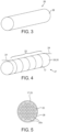
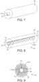
Figure 3 is a side perspective view of a porous heating element support; -
Figure 4 is a side perspective view of a porous heating element support and a coil; -
Figure 5 is an end view of a porous heating element support and a coil; -
Figure 6 is a schematic sectional view of an electronic cigarette having a parallel coil; -
Figure 7 is a side perspective view of an outer porous heating element support; -
Figure 8 is a side perspective view of an outer porous heating element support and a coil; -
Figure 9 is an end view of an outer porous heating element support and a coil; -
Figure 10 is an end view of a porous heating element support with channels, and a coil; -
Figure 11 is an end view of a porous heating element support having an octagonal cross-sectional shape, and a coil; -
Figure 12 is an end view of a porous heating element support having a four arm cross cross-sectional shape, and a coil; -
Figure 13 is an end view of an outer porous heating element support and a coil; -
Figure 14 is an end view of an outer porous heating element support and a coil; and -
Figure 15 is an end view of an two part outer porous heating element support and a coil. - In an embodiment there is provided an electronic vapour provision device comprising a power cell, a vaporiser and a liquid store, where the vaporiser comprises a heating element and a heating element support, wherein the liquid store comprises a porous material. The electronic vapour provision device may be an electronic cigarette. By having a liquid store comprising porous material, the liquid can be retained more efficiently, and also release and storage of the liquid is more controlled through the wicking action of the porous material.
- The liquid store may comprise a solid porous material or a rigid porous material. For example, the liquid store may comprise a porous ceramic material. A solid porous material is advantageous since it is not open to deformation so the properties can be set and maintained. The shape can be defined at the manufacturing stage and this specific shape can be retained in the device to give consistency in device usage.
- The liquid store may not comprise an outer liquid store container. Providing a solid porous material removes the need for an outer liquid store container and therefore gives a more efficient storage means.
- The porous material may be optimized for liquid retention and wicking and/or for liquid glycerine retention and wicking. Moreover, the porous material may have pores of substantially equal size. The porous material may comprise pores distributed evenly throughout the material. Moreover, the porous material may be configured such that the majority of the material volume comprises open pores for liquid storage. The liquid store may be sealed on at least part of an outer surface region to inhibit porosity in that region.
- The porous material has smaller pores in a region next to the heating element and larger pores further from the heating element. The porous material may have a gradient of pore sizes ranging from smaller pores next to the heating element to larger pores further from the heating element.
- The liquid store may be configured to wick liquid onto the heating element. The configuration of pores acts to determine the wicking effect of the storage medium, such that a more efficient means of transmission of liquid onto the heating element can be achieved.
- The heating element support may form part of the liquid store, a separate additional liquid store or the entirety of the liquid store. By removing the requirement for a separate support, the number of components is reduced giving a simpler and cheaper device and enabling a larger liquid store to be used for increased capacity.
- The heating element may be supported from its outside by the heating element support. Alternatively or additionally, the heating element may be supported from its inside by the heating element support.
- One or more gaps may be provided between the heating element and the heating element support. Providing a gap between the heating element and the heating element support allows liquid to be gathered and stored in the gap region for vaporisation. The gap can also act to wick liquid onto the heating element. Also, providing a gap between the heating element and support means that a greater surface area of the heating element is exposed thereby giving a greater surface area for heating and vaporisation.
- The heating element may be a heating coil, such as a wire coil. The heating coil may be coiled so as to be supported along its length by the heating element support. Moreover, the turns of the heating coil may be supported by the heating element support. For example, the turns of the heating coil may be in contact with the heating element support. One or more gaps may be provided between the heating coil and the heating element support. By providing a gap between a coil turn and the support, liquid can be wicked into the gap and held in the gap for vaporisation. In particular, liquid can be wicked by the spaces between coil turns and into the gap between a coil turn and the support.
- The vaporiser may further comprise a vaporisation cavity such that, in use, the vaporisation cavity is a negative pressure cavity. At least part of the heating element may be inside the vaporisation cavity. By having the heating element in the vaporisation cavity, which in turn is a negative pressure cavity when a user inhales through the electronic cigarette, the liquid is directly vaporised and inhaled by the user.
- The electronic vapour provision device may comprise a mouthpiece section and the vaporiser may form part of the mouthpiece section. Moreover, the liquid store may form part of the mouthpiece section. For example, the liquid store may substantially fill the mouthpiece section.
- Referring to
Figure 1 there is shown an embodiment of the electronicvapour provision device 1 in the form of anelectronic cigarette 1 comprising amouthpiece 2 and abody 3. Theelectronic cigarette 1 is shaped like a conventional cigarette having a cylindrical shape. Themouthpiece 2 has anair outlet 4 and theelectronic cigarette 1 is operated when a user places themouthpiece 2 of theelectronic cigarette 1 in their mouth and inhales, drawing air through theair outlet 4. Both themouthpiece 2 andbody 3 are cylindrical and are configured to connect to each other coaxially so as to form the conventional cigarette shape. -
Figures 2 shows an example of theelectronic cigarette 1 ofFigure 1 . Thebody 3 comprises two detachable parts, comprising abattery assembly 5 part and avaporiser 6 part, and themouthpiece 2 comprises a liquid store 7. Theelectronic cigarette 1 is shown in its assembled state, wherein thedetachable parts mouthpiece 2,vaporiser 6,battery assembly 5. Liquid wicks from the liquid store 7 to thevaporiser 6. Thebattery assembly 5 provides electrical power to thevaporiser 6 via mutual electrical contacts of thebattery assembly 5 and thevaporiser 6. Thevaporiser 6 vaporises the wicked liquid and the vapour passes out of theair outlet 4. The liquid may for example comprise a nicotine solution. - The
battery assembly 5 comprises abattery assembly casing 8, apower cell 9,electrical contacts 10 and acontrol circuit 11. - The
battery assembly casing 8 comprises a hollow cylinder which is open at afirst end 12. For example, thebattery assembly casing 8 may be plastic. Theelectrical contacts 10 are located at thefirst end 12 of thecasing 8, and thepower cell 9 andcontrol circuit 11 are located within the hollow of thecasing 8. Thepower cell 9 may for example be a Lithium Cell. - The
control circuit 11 includes anair pressure sensor 13 and acontroller 14 and is powered by thepower cell 9. Thecontroller 14 is configured to interface with theair pressure sensor 13 and to control provision of electrical power from thepower cell 9 to thevaporiser 6. - The
vaporiser 6 comprises avaporiser casing 15,electrical contacts 16, aheating element 17, awicking element 18, avaporisation cavity 19 and aheating element support 20. - The
vaporiser casing 15 comprises a hollow cylinder which is open at both ends with anair inlet 21. For example, thevaporiser casing 15 may be formed of an aluminium alloy. Theair inlet 21 comprises a hole in thevaporiser casing 15 at afirst end 22 of thevaporiser casing 15. Theelectrical contacts 16 are located at thefirst end 22 of thevaporiser casing 15. - The
first end 22 of thevaporiser casing 15 is releasably connected to thefirst end 12 of thebattery assembly casing 8, such that theelectrical contacts 16 of the vaporiser are electrically connected to theelectrical contacts 10 of the battery assembly. For example, thedevice 1 may be configured such that thevaporiser casing 15 connects to thebattery assembly casing 8 by a threaded connection. - The
heating element 17 is formed of a single wire and comprises aheating element coil 23 and twoleads 24, as is illustrated inFigures 4 and 5 . For example, the heating element may be formed of Nichrome. Thecoil 23 comprises a section of the wire where the wire is formed into a helix about an axis A. At either end of thecoil 23, the wire departs from its helical form to provide theleads 24. The leads 24 are connected to theelectrical contacts 16 and are thereby configured to route electrical power, provided by thepower cell 9, to thecoil 23. - The wire of the
coil 23 is approximately 0.12 mm in diameter. The coil is approximately 25 mm in length, has an internal diameter of approximately 1 mm and a helix pitch of approximately 420 micrometers. The void between the successive turns of thecoil 23 is therefore approximately 300 micrometers. - The
heating element 17 is located towards thesecond end 25 of thevaporiser casing 15 and is orientated such that the axis A of thecoil 23 is perpendicular to the cylindrical axis B of thevaporiser casing 15. Thecoil 23 of theheating element 17 is thus perpendicular to the longitudinal axis C of theelectronic cigarette 1. - The wicking
element 18 extends from thevaporiser casing 15 into contact with the liquid store 7 of themouthpiece 2. The wickingelement 18 is configured to wick liquid in the direction W from the liquid store 7 of themouthpiece 2 to theheating element 17. In more detail, thewick 18 comprises an arc of porous material extending from a first end of thecoil 23, out past thesecond end 25 of thevaporiser casing 14 and back to a second end of the coil. For example, the porous material may be nickel foam, wherein the porosity of the foam is such that the described wicking occurs. - The
vaporisation cavity 19 comprises a region within the hollow of thevaporiser casing 15 in which liquid is vaporised. Theheating element 17,heating element support 20 andportions 26 of thewicking element 18 are situated within thevaporisation cavity 19. - The
heating element support 20 is configured to support theheating element 17 and to facilitate vaporisation of liquid by theheating element 17. Theheating element support 20 is an inner support and is illustrated inFigures 3, 4 and 5 . Thesupport 20 comprises a rigid cylinder of porous ceramic material. For example, the porous ceramic material is shown to havepores 20a distributes throughout the material. Thesupport 20 is situated coaxially within the helix of theheating element coil 23 and is slightly longer than thecoil 23, such that the ends of thesupport 20 protrude from the ends of thecoil 23. The diameter of thecylindrical support 20 is similar to the inner diameter of the helix. As a result, the wire of thecoil 23 is substantially in contact with thesupport 20 and is thereby supported, facilitating maintenance of the shape of thecoil 23. Theheating element coil 23 is thus coiled, or wrapped, around theheating element support 20. The solidity provides a stable and secure structure to hold thecoil 23 in place. The combination of thesupport 20 and thecoil 23 of theheating element 17 provides aheating rod 27, as illustrated inFigures 4 and 5 . The heating rod is later described in more detail with reference toFigures 4 and 5 . - The
surface 28 of thesupport 20 provides a route for liquid from thewick element 18 to wick onto and along, improving the provision of liquid to the vicinity of theheating element 17 for vaporisation. Thesurface 28 of thesupport 20 also provides surface area for exposing wicked liquid to the heat of theheating element 17. The porosity of the support allows liquid to be stored in theheating element support 20. The support is thus a further liquid store. - The
mouthpiece 2 comprises amouthpiece casing 29. Themouthpiece casing 29 comprises a hollow cylinder which is open at afirst end 30, with theair outlet 4 comprising a hole in thesecond end 31 of the casing. For example, the mouthpiece casing may be formed of plastic. - The liquid store 7 is situated within the hollow of the
mouthpiece casing 29. For example, the liquid store may comprise foam, wherein the foam is substantially saturated in the liquid intended for vaporisation. The cross-sectional area of the liquid store 7 is less than that of the hollow of the mouthpiece casing so as to form anair passageway 32 between thefirst end 30 of themouthpiece casing 2 and theair outlet 4. - The
first end 30 of themouthpiece casing 29 is releasably connected to thesecond end 25 of thevaporiser casing 15, such that the liquid store 7 is in contact with aportion 33 of thewicking element 18 which protrudes from thevaporiser 6. - Liquid from the liquid store 7 is absorbed by the wicking
element 18 and wicks along route W throughout the wickingelement 18. Liquid then wicks from the wickingelement 18 onto and along thecoil 23 of theheating element 17, and onto and along thesupport 20. - There exists a continuous
inner cavity 34 within theelectronic cigarette 1 formed by the adjacent hollow interiors' of themouthpiece casing 29, thevaporiser casing 15 and thebattery assembly casing 8. - In use, a user sucks on the
second end 31 of themouthpiece 2. This causes a drop in the air pressure throughout theinner cavity 34 of theelectronic cigarette 1, particularly at theair outlet 4. - The pressure drop within the
inner cavity 34 is detected by thepressure sensor 13. In response to detection of the pressure drop by the pressure sensor, thecontroller 14 triggers the provision of power from thepower cell 9 to theheating element 17 via theelectrical contacts heating element 17 therefore heats up. Once thecoil 17 heats up, liquid in thevaporisation cavity 19 is vaporised. In more detail, liquid on theheating element 17 is vaporised, liquid on theheating element support 20 is vaporised and liquid inportions 26 of thewicking element 18 which are in the immediate vicinity of theheating element 17 may be vaporised. - The pressure drop within the
inner cavity 34 also causes air from outside of theelectronic cigarette 1 to be drawn, along route F, through the inner cavity from theair inlet 21 to theair outlet 4. As air is drawn along route F, it passes through thevaporisation cavity 19 and theair passageway 32. The vaporised liquid is therefore conveyed by the air movement along theair passageway 32 and out of theair outlet 4 to be inhaled by the user. In passing through the vaporisation cavity, along route F, the air moves over theheating element 17 in a direction substantially perpendicular to the axis A of thecoil 23. - As the air containing the vaporised liquid is conveyed to the
air outlet 4, some of the vapour may condense, producing a fine suspension of liquid droplets in the airflow. Moreover, movement of air through thevaporiser 6 as the user sucks on themouthpiece 2 can lift fine droplets of liquid off of thewicking element 18, theheating element 17 and/or theheating element support 20. The air passing out of the outlet may therefore comprise an aerosol of fine liquid droplets as well as vaporised liquid. - The pressure drop within the
vaporisation cavity 19 also encourages further wicking of liquid from the liquid store 7, along the wickingelement 18, to thevaporisation cavity 19. -
Figure 6 shows a further example of theelectronic cigarette 1 ofFigure 1 . Thebody 3 is referred to herein as a battery assembly 50, and themouthpiece 2 includes aliquid store 51 and a vaporiser 52. Theelectronic cigarette 1 is shown in its assembled state, wherein thedetachable parts liquid store 51 to the vaporiser 52. The battery assembly 50 provides electrical power to the vaporiser 52 via mutual electrical contacts of the battery assembly 50 and themouthpiece 2. The vaporiser 52 vaporises the wicked liquid and the vapour passes out of theair outlet 4. The liquid may for example comprise a nicotine solution. - The battery assembly 50 comprises a
battery assembly casing 53, apower cell 54,electrical contacts 55 and acontrol circuit 56. - The
battery assembly casing 53 comprises a hollow cylinder which is open at afirst end 57. For example, thebattery assembly casing 53 may be plastic. Theelectrical contacts 55 are located at thefirst end 57 of thecasing 53, and thepower cell 54 andcontrol circuit 56 are located within the hollow of thecasing 53. Thepower cell 54 may for example be a Lithium Cell. - The
control circuit 56 includes anair pressure sensor 58 and acontroller 59 and is powered by thepower cell 54. Thecontroller 59 is configured to interface with theair pressure sensor 58 and to control provision of electrical power from thepower cell 54 to the vaporiser 52, via theelectrical contacts 55. - The
mouthpiece 2 further includes amouthpiece casing 60 andelectrical contacts 61. Themouthpiece casing 60 comprises a hollow cylinder which is open at afirst end 62, with theair outlet 4 comprising a hole in thesecond end 63 of thecasing 60. Themouthpiece casing 60 also comprises anair inlet 64, comprising a hole near thefirst end 62 of thecasing 60. For example, the mouthpiece casing may be formed of aluminium. - The
electrical contacts 61 are located at the first end of thecasing 60. Moreover, thefirst end 62 of themouthpiece casing 60 is releasably connected to thefirst end 57 of thebattery assembly casing 53, such that theelectrical contacts 61 of themouthpiece 2 are electrically connected to theelectrical contacts 55 of the battery assembly 50. For example, thedevice 1 may be configured such that themouthpiece casing 60 connects to the battery assembly casing 53 by a threaded connection. - The
liquid store 51 is situated within the hollow mouthpiece casing 60 towards thesecond end 63 of thecasing 60. Theliquid store 51 comprises a cylindrical tube of porous material saturated in liquid. The outer circumference of theliquid store 51 matches the inner circumference of themouthpiece casing 60. The hollow of theliquid store 51 provides anair passageway 65. For example, the porous material of theliquid store 51 may comprise foam, wherein the foam is substantially saturated in the liquid intended for vaporisation. - The vaporiser 52 comprises a
vaporisation cavity 66, aheating element support 67 and a heating element 68. - The
vaporisation cavity 66 comprises a region within the hollow of themouthpiece casing 60 in which liquid is vaporised. The heating element 68 and aportion 69 of thesupport 67 are situated within thevaporisation cavity 66. - The
heating element support 67 is configured to support the heating element 68 from the outside and to facilitate vaporisation of liquid by the heating element 68 and is illustrated inFigures 7 to 9 . Because thesupport 67 is located outside of the heating element 68, its size is not restricted by the size of the heating element, and so can be much larger than those of the embodiments described above. This facilitates the storing of more liquid by the porousheating element support 67 than those of the embodiments described above. Thesupport 67 comprises a hollow cylinder of rigid, porous material and is situated within themouthpiece casing 60, towards thefirst end 62 of thecasing 60, such that it abuts theliquid store 51. The porous material haspores 67a distributes throughout. The outer circumference of thesupport 67 matches the inner circumference of themouthpiece casing 60. The hollow of the support comprises a longitudinal,central channel 70 through the length of thesupport 67. Thechannel 70 has a square cross-sectional shape, the cross-section being perpendicular to the longitudinal axis of the support. - The
support 67 acts as a wicking element, as it is configured to wick liquid in the direction W from theliquid store 51 of themouthpiece 2 to the heating element 68. For example, the porous material of thesupport 67 may be nickel foam, wherein the porosity of the foam is such that the described wicking occurs. Once liquid wicks W from theliquid store 51 to thesupport 67, it is stored in the porous material of thesupport 67. Thus, thesupport 67 is an extension of theliquid store 51. - The heating element 68 is formed of a single wire and comprises a
heating element coil 71 and twoleads 72, as is illustrated inFigures 8 and 9 . For example, the heating element 68 may be formed of Nichrome. Thecoil 71 comprises a section of the wire where the wire is formed into a helix about an axis A. At either end of thecoil 71, the wire departs from its helical form to provide theleads 72. The leads 72 are connected to theelectrical contacts 61 and are thereby configured to route electrical power, provided by thepower cell 54, to thecoil 71. - The wire of the
coil 71 is approximately 0.12 mm in diameter. The coil is approximately 25 mm in length, has an internal diameter of approximately 1 mm and a helix pitch of approximately 420 micrometers. The void between the successive turns of thecoil 71 is therefore approximately 300 micrometers. - The
coil 71 of the heating element 68 is located coaxially within thechannel 70 of the support. Theheating element coil 71 is thus coiled within thechannel 70 of theheating element support 67. Moreover, the axis A of thecoil 71 is thus parallel to the cylindrical axis B of themouthpiece casing 60 and the longitudinal axis C of theelectronic cigarette 1. - The
coil 71 is the same length as thesupport 67, such that the ends of thecoil 71 are flush with the ends of thesupport 67. The outer diameter of the helix of thecoil 71 is similar to the cross-sectional width of thechannel 70. As a result, the wire of thecoil 71 is in contact with thesurface 73 of thechannel 70 and is thereby supported, facilitating maintenance of the shape of thecoil 71. Each turn of the coil is in contact with thesurface 73 of thechannel 70 at acontact point 75 on each of the fourwalls 73 of thechannel 70. The combination of thecoil 71 and thesupport 67 provides aheating rod 74, as illustrated inFigures 8 and 9 . Theheating rod 74 is later described in more detail with reference toFigures 8 and 9 . - The
inner surface 73 of thesupport 67 provides a surface for liquid to wick onto thecoil 71 at thepoints 75 of contact between thecoil 71 and thechannel 70walls 73. Theinner surface 73 of thesupport 67 also provides surface area for exposing wicked liquid to the heat of the heating element 68. - There exists a continuous
inner cavity 76 within theelectronic cigarette 1 formed by the adjacent hollow interiors' of themouthpiece casing 60 and thebattery assembly casing 53. - In use, a user sucks on the
second end 63 of themouthpiece casing 60. This causes a drop in the air pressure throughout theinner cavity 76 of theelectronic cigarette 1, particularly at theair outlet 4. - The pressure drop within the
inner cavity 76 is detected by thepressure sensor 58. In response to detection of the pressure drop by thepressure sensor 58, thecontroller 59 triggers the provision of power from thepower cell 54 to the heating element 68 via theelectrical contacts coil 17 heats up, liquid in thevaporisation cavity 66 is vaporised. In more detail, liquid on thecoil 71 is vaporised, liquid on theinner surface 73 of theheating element support 67 is vaporised and liquid in theportions 22 of thesupport 67 which are in the immediate vicinity of the heating element 68 may be vaporised. - The pressure drop within the
inner cavity 76 also causes air from outside of theelectronic cigarette 1 to be drawn, along route F, through the inner cavity from theair inlet 64 to theair outlet 4. As air is drawn along route F, it passes through thevaporisation cavity 66, picking up vaporised liquid, and theair passageway 65. The vaporised liquid is therefore conveyed along theair passageway 65 and out of theair outlet 4 to be inhaled by the user. In passing through the vaporisation cavity, along route F, the air moves over the heating element 68 in a direction substantially parallel to the axis A of thecoil 71. - As the air containing the vaporised liquid is conveyed to the
air outlet 4, some of the vapour may condense, producing a fine suspension of liquid droplets in the airflow. Moreover, movement of air through the vaporiser 52 as the user sucks on themouthpiece 2 can lift fine droplets of liquid off of the heating element 68 and/or theheating element support 67. The air passing out of theair outlet 4 may therefore comprise an aerosol of fine liquid droplets as well as vaporised liquid. - With reference to
Figures 8 and 9 , due to the cross-sectional shape of the channel,gaps 80 are formed between theinner surface 73 of theheating element support 67 and thecoil 71. In more detail, where the wire of thecoil 71 passes between contact points 75, agap 80 is provided between the wire and the area of theinner surface 73 closest to the wire due to the wire substantially maintaining its helical form. The distance between the wire and thesurface 73 at eachgap 80 is in the range of 10 micrometers to 500 micrometers. Thegaps 80 are configured to facilitate the wicking of liquid onto thecoil 71 through capillary action at thegaps 80. Thegaps 80 also provide areas in which liquid can gather prior to vaporisation, and thereby provide areas for liquid to be stored prior to vaporisation. Thegaps 80 also expose more of thecoil 71 for increased vaporisation in these areas. - Many alternatives and variations to the embodiments described above are possible. For example, alternatives and variations to the embodiments of
Figures 2 to 5 are as follows. -
Figures 10 to 12 show other examples of porous heating element supports 20 with acoil 23 wound around. These differ from the example shown inFigures 2 to 5 and from each other by the shape of theheating element support 20. In each of the examples ofFigures 10 to 12 ,gaps 80 are provided between theheating element 17 and thesupport 20 by virtue of the cross-sectional shape of the support. In more detail, where the wire of thecoil 23 passes over a depression in thesurface 28, agap 80 is provided between the wire and the area of thesurface 28 immediately under the wire due to the wire substantially maintaining its helical form. Thegaps 80 are therefore disposed in a radial direction from the axis A of the coil, between thesurface 28 of thesupport 20 and the wire of thecoil 23. The distance between the wire and thesurface 28 at eachgap 80 is in the range of 10 micrometers to 500 micrometers. Thegaps 80 are configured to facilitate the wicking of liquid onto and along the length of thesupport 20 through capillary action at thegaps 80. As with the heating rods ofFigures 8 and 9 , thegaps 80 also facilitate the wicking of liquid onto theheating element 17 from theporous support 20 through capillary action at thegaps 80. Thegaps 80 also provide areas in which liquid can gather on thesurface 28 of thesupport 20 prior to vaporisation, and thereby provide areas for liquid to be stored prior to vaporisation. Thegaps 80 also expose more of thecoil 23 for increased vaporisation in these areas. -
Figure 10 shows aheating element support 20 having a generally cylindrical shape but having foursurface channels 81 running lengthwise and spaced equally around thesupport 20. Thecoil 23 is wound around thesupport 20 andgaps 80 are provided where the coil turns overlap thechannels 81. In more detail, where the wire of thecoil 23 passes over achannel 81, agap 80 is provided between the wire and the area of thesurface 28 immediately under the wire. - The
heating element support 20 is porous and stores liquid. Thegaps 80 provided by thechannels 81 have two functions. Firstly, they provide a means for liquid to be wicked both onto thecoil 23 and into theheating element support 20 by capillary action. Secondly, they expose thecoil 23 surface in the area of thechannels 81 thereby increasing the vaporisation surface of thecoil 23. - In
Figure 11 , theheating element support 20 has an octagonal outer cross-sectional shape, perpendicular to the lengthwise direction. Thecoil 23 is wound around this support. Because thecoil 23 is wire of some rigidity, the wire form does not match the exact outer form of the support, but tends to be curved. Thus,gaps 80 provided between the outer octagonal surface of theheating element support 20 and thecurved coil 23. - Again, the
heating element support 20 is porous for liquid storage and thegaps 80 provide a means of wicking liquid onto thecoil 23, and expose a greater surface of thecoil 23 for increased vaporisation. - In
Figure 12 , theheating element support 20 has an outer cross-sectional shape equal to a four arm cross. Thecoil 23 is wound around thesupport 20 andgaps 80 are provided between respective arms and thecoil 23 surface. Thesegaps 80 provide the same advantages already described. - Moreover, where
channels 81 are provided in theheating element support 20, a number other than one or fourchannels 81 can be used. - Furthermore,
channels 81 have been described as longitudinal grooves along thesurface 28 of cylindrical supports 20. However, thechannels 81 may, for example, alternatively or additionally comprise helical grooves in thesurface 28 of acylindrical support 20, spiralling about the axis of the support. Alternatively or additionally thechannels 81 may comprise circumferential rings around thesurface 28 of thesupport 20. - In embodiments, the
inner support 20 is described as being slightly longer than thecoil 23, such that it protrudes from either end of thecoil 23. Alternatively, thesupport 20 may be shorter in length than thecoil 23 and may therefore reside entirely within the bounds of the coil. - Furthermore, example alternatives and variations to the embodiments of
Figures 6 to 9 are as follows.Figures 13 to 15 show other examples of outer porous heating element supports 67 with aninternal coil 71. These differ from the example shown inFigures 7 and 9 and from each other by the shape of theheating element support 67. -
Figure 13 shows a device similar to that shown inFigure 9 with the exception that theinternal channel 70 has a circular cross-sectional shape rather than a square. This provides an arrangement where acoil 71 is fitted into theinternal channel 70 and is in contact with thechannel 70 surface along the length of thechannel 70 substantially without gaps in the contact areas. This extra contact provides an increased means for liquid to be wicked onto thecoil 71 and a general decrease in the vaporisation area of thecoil 71. - In
Figure 14 a device is shown similar to that shown inFigure 9 . In this example, the outer cross-sectional shape of theheating element support 67 is a square rather than a circle. -
Figure 15 shows aheating element support 67 comprising afirst support section 85 and asecond support section 86. Theheating element support 67 is generally cylindrical in shape and thefirst support section 85 andsecond support section 86 are half cylinders with generally semi-circular cross-sections, which are joined together to form the cylindrical shape of theheating element support 67. - The
first support section 85 andsecond support section 86 each have aside channel 87, orgroove 87, running along their respective lengths, along the middle of their otherwise flat longitudinal surfaces. When thefirst support section 85 is joined to thesecond support section 86 to form theheating element support 67, theirrespective side channels 87 together form the heating elements support 67internal channel 70. - In this example, the combined
side channels 87 form aninternal channel 70 having a square cross-sectional shape. Thus, theside channels 87 are each rectangular in cross-section. Thecoil 71 is situated within theheating element support 67internal channel 70. Having aheating element support 67 that comprises twoseparate parts coil 71 can be fitted into theside channel 87 of thefirst support section 85, and thesecond support section 86 can be placed on top to form the completedheating element support 67. -
Internal support channels 70 with cross-sectional shapes other than those described could be used. - Moreover, the
coil 71 may be shorter in length than theouter support 67 and may therefore reside entirely within the bounds of the support. Alternatively, thecoil 71 may be longer than theouter support 67. - In embodiments, the
support 67 may be located partially or entirely withinliquid store 51. For example, thesupport 67 may be located coaxially within the tube of theliquid store 51. - Furthermore, example alternatives and variations to the embodiments described above are as follows.
- An electronic vapour provision device comprising an
electronic cigarette 1 is described herein. However, other types of electronic vapour provision device are possible. - The wire of the
coil coil coil - The internal diameter of the
coil coil - The pitch of the
helical coil - Furthermore, although the distance of the voids between turns of the
coil - The size of the
gaps 80 may be different to that described above. - Furthermore, the electronic
vapour provision device 1 is not restricted to the sequence of components described and other sequences could be used such as thecontrol circuit liquid store 7, 51 being in the electronicvapour provision device 1body 3 rather than themouthpiece 2. - The electronic
vapour provision device 1 ofFigure 2 is described as comprising three detachable parts, themouthpiece 2, thevaporiser 6 and thebattery assembly 5. Alternatively, the electronicvapour provision device 1 may be configured such theseparts mouthpiece 2, thevaporiser 6 and thebattery assembly 5 may not be detachable. As a further alternative, themouthpiece 2 and thevaporiser 6 may comprise a single integrated unit, or thevaporiser 6 and thebattery assembly 5 may comprise a single integrated unit. - The electronic
vapour provision device 1 ofFigure 6 is described as comprising two detachable parts, themouthpiece 2 and the body comprising the battery assembly 50. Alternatively, thedevice 1 may be configured such theseparts 2,50 are combined into a single integrated unit. In other words, themouthpiece 2 and thebody 3 may not be detachable. - The
heating element 17, 68 is not restricted to being acoil - An
air pressure sensor - The
heating element 17, 68 is not restricted to being a uniform coil. - The porous material of the
heating element support - The
heating element support - Reference herein to a
vaporisation cavity - Although examples have been shown and described it will be appreciated by those skilled in the art that various changes and modifications might be made without departing from the scope of the invention.
- In order to address various issues and advance the art, the entirety of this disclosure shows by way of illustration various embodiments which may be practiced and provide for superior electronic vapour provision. The advantages and features of the disclosure are of a representative sample of embodiments only, and are not exhaustive and/or exclusive. They are presented only to assist in understanding and teach the claimed features. It is to be understood that advantages, embodiments, examples, functions, features, structures, and/or other aspects of the disclosure are not to be considered limitations on the disclosure and that other embodiments may be utilised and modifications may be made without departing from the scope of the disclosure. Various embodiments may suitably comprise, consist of, or consist essentially of, various combinations of the disclosed elements, components, features, parts, steps, means, etc. In addition, the disclosure includes other inventions not presently claimed, but which may be claimed in the future. Any feature of any embodiment can be used independently of, or in combination with, any other feature. The scope of protection is defined by the claims.
Claims (14)
- An electronic vapour provision device (1) comprising a power cell (9), a vaporiser (6) and a liquid store (7), where the vaporiser comprises a heating element (17) and a heating element support (20), wherein the liquid store comprises a porous material, and wherein the heating element support is or forms part of the liquid store, and wherein the porous material comprises smaller pores in the region next to the heating element and larger pores further from the heating element.
- The electronic vapour provision device of claim 1, wherein the electronic vapour provision device is an electronic cigarette.
- The electronic vapour provision device of any preceding claim, wherein the liquid store comprises a porous ceramic material.
- The electronic vapour provision device of any preceding claim, wherein the liquid store is sealed on at least part of an outer surface region to inhibit porosity in that region.
- The electronic vapour provision device of any preceding claim, wherein the liquid store is configured, in use, to wick liquid onto the heating element.
- The electronic vapour provision device of any preceding claim, wherein the heating element is a heating coil, and wherein the heating coil is a wire coil.
- The electronic vapour provision device of claim 6, wherein the turns of the heating coil are in contact with the heating element support and are thereby supported by the heating element support.
- The electronic vapour provision device of any preceding claim, wherein one or more gaps are provided between the heating element and the heating element support.
- The electronic vapour provision device of any preceding claim, wherein the vaporiser further comprises a vaporisation cavity such that, in use, the vaporisation cavity is a negative pressure cavity.
- The electronic vapour provision device of claim 9, wherein at least part of the heating element is inside the vaporisation cavity.
- The electronic vapour provision device of any preceding claim, wherein the electronic vapour provision device comprises a mouthpiece section and the vaporiser forms part of the mouthpiece section.
- The electronic vapour provision device of claim 11, wherein the liquid store forms part of the mouthpiece section or substantially fills the mouthpiece section.
- The electronic vapour provision device of any preceding claim, further comprising an air outlet for vaporised liquid from the heating element.
- A mouthpiece section for an electronic vapour provision device according to any preceding claim, the mouthpiece section including a vaporiser and a liquid store, the vaporiser comprising a heating element and a heating element support, wherein the liquid store comprises a porous material, and wherein the heating element support is or forms part of the liquid store, and wherein the porous material comprises smaller pores in the region next to the heating element and larger pores further from the heating element.
Priority Applications (4)
| Application Number | Priority Date | Filing Date | Title |
|---|---|---|---|
| EP18195423.1A EP3446580B1 (en) | 2012-07-16 | 2013-07-15 | Electronic vapour provision device |
| EP16177005.2A EP3106047B1 (en) | 2012-07-16 | 2013-07-15 | Electronic vapour provision device |
| EP23176770.8A EP4245165A3 (en) | 2012-07-16 | 2013-07-15 | Electronic vapour provision device |
| PL13736600T PL2871984T3 (en) | 2012-07-16 | 2013-07-15 | Electronic vapour provision device |
Applications Claiming Priority (2)
| Application Number | Priority Date | Filing Date | Title |
|---|---|---|---|
| GB1212606.6A GB2504076A (en) | 2012-07-16 | 2012-07-16 | Electronic smoking device |
| PCT/EP2013/064952 WO2014012906A1 (en) | 2012-07-16 | 2013-07-15 | Electronic vapour provision device |
Related Child Applications (6)
| Application Number | Title | Priority Date | Filing Date |
|---|---|---|---|
| EP18195423.1A Division-Into EP3446580B1 (en) | 2012-07-16 | 2013-07-15 | Electronic vapour provision device |
| EP18195423.1A Division EP3446580B1 (en) | 2012-07-16 | 2013-07-15 | Electronic vapour provision device |
| EP23176770.8A Division EP4245165A3 (en) | 2012-07-16 | 2013-07-15 | Electronic vapour provision device |
| EP23176770.8A Division-Into EP4245165A3 (en) | 2012-07-16 | 2013-07-15 | Electronic vapour provision device |
| EP16177005.2A Division-Into EP3106047B1 (en) | 2012-07-16 | 2013-07-15 | Electronic vapour provision device |
| EP16177005.2A Division EP3106047B1 (en) | 2012-07-16 | 2013-07-15 | Electronic vapour provision device |
Publications (3)
| Publication Number | Publication Date |
|---|---|
| EP2871984A1 EP2871984A1 (en) | 2015-05-20 |
| EP2871984B1 EP2871984B1 (en) | 2016-09-07 |
| EP2871984B2 true EP2871984B2 (en) | 2024-02-28 |
Family
ID=46799669
Family Applications (4)
| Application Number | Title | Priority Date | Filing Date |
|---|---|---|---|
| EP23176770.8A Pending EP4245165A3 (en) | 2012-07-16 | 2013-07-15 | Electronic vapour provision device |
| EP18195423.1A Active EP3446580B1 (en) | 2012-07-16 | 2013-07-15 | Electronic vapour provision device |
| EP13736600.1A Active EP2871984B2 (en) | 2012-07-16 | 2013-07-15 | Electronic vapour provision device |
| EP16177005.2A Active EP3106047B1 (en) | 2012-07-16 | 2013-07-15 | Electronic vapour provision device |
Family Applications Before (2)
| Application Number | Title | Priority Date | Filing Date |
|---|---|---|---|
| EP23176770.8A Pending EP4245165A3 (en) | 2012-07-16 | 2013-07-15 | Electronic vapour provision device |
| EP18195423.1A Active EP3446580B1 (en) | 2012-07-16 | 2013-07-15 | Electronic vapour provision device |
Family Applications After (1)
| Application Number | Title | Priority Date | Filing Date |
|---|---|---|---|
| EP16177005.2A Active EP3106047B1 (en) | 2012-07-16 | 2013-07-15 | Electronic vapour provision device |
Country Status (17)
| Country | Link |
|---|---|
| US (3) | US9943108B2 (en) |
| EP (4) | EP4245165A3 (en) |
| JP (3) | JP2015524258A (en) |
| KR (4) | KR102489540B1 (en) |
| CN (2) | CN109123808A (en) |
| AU (1) | AU2013292106B2 (en) |
| BR (1) | BR112015000968B1 (en) |
| CA (1) | CA2878973C (en) |
| ES (3) | ES2949362T3 (en) |
| GB (1) | GB2504076A (en) |
| HK (2) | HK1204236A1 (en) |
| HU (2) | HUE063629T2 (en) |
| MY (2) | MY198478A (en) |
| PL (3) | PL3106047T3 (en) |
| RU (1) | RU2596108C1 (en) |
| UA (1) | UA110897C2 (en) |
| WO (1) | WO2014012906A1 (en) |
Families Citing this family (182)
| Publication number | Priority date | Publication date | Assignee | Title |
|---|---|---|---|---|
| US20160345631A1 (en) | 2005-07-19 | 2016-12-01 | James Monsees | Portable devices for generating an inhalable vapor |
| US7726320B2 (en) | 2006-10-18 | 2010-06-01 | R. J. Reynolds Tobacco Company | Tobacco-containing smoking article |
| AT507187B1 (en) | 2008-10-23 | 2010-03-15 | Helmut Dr Buchberger | INHALER |
| US8897628B2 (en) * | 2009-07-27 | 2014-11-25 | Gregory D. Conley | Electronic vaporizer |
| US10857311B2 (en) | 2010-01-12 | 2020-12-08 | Omega Life Science Ltd. | Method and apparatus for producing fine concentrated aerosol |
| JP5681819B2 (en) | 2011-02-11 | 2015-03-11 | バットマーク・リミテッド | Inhaler components |
| AT510837B1 (en) | 2011-07-27 | 2012-07-15 | Helmut Dr Buchberger | INHALATORKOMPONENTE |
| US9078473B2 (en) | 2011-08-09 | 2015-07-14 | R.J. Reynolds Tobacco Company | Smoking articles and use thereof for yielding inhalation materials |
| UA110646C2 (en) | 2011-09-06 | 2016-01-25 | Брітіш Амерікан Тобакко (Інвестментс) Лімітед | Devices for the heating of smoking materials |
| ES2859223T3 (en) | 2011-09-06 | 2021-10-01 | Nicoventures Trading Ltd | Heating of smokable material |
| AT511344B1 (en) | 2011-10-21 | 2012-11-15 | Helmut Dr Buchberger | INHALATORKOMPONENTE |
| GB201207039D0 (en) | 2012-04-23 | 2012-06-06 | British American Tobacco Co | Heating smokeable material |
| GB2504077A (en) | 2012-07-16 | 2014-01-22 | Nicoventures Holdings Ltd | Electronic smoking device |
| GB2504075A (en) | 2012-07-16 | 2014-01-22 | Nicoventures Holdings Ltd | Electronic smoking device |
| GB2504074A (en) | 2012-07-16 | 2014-01-22 | Nicoventures Holdings Ltd | Electronic cigarette |
| GB2504076A (en) | 2012-07-16 | 2014-01-22 | Nicoventures Holdings Ltd | Electronic smoking device |
| US10034988B2 (en) | 2012-11-28 | 2018-07-31 | Fontem Holdings I B.V. | Methods and devices for compound delivery |
| US10279934B2 (en) | 2013-03-15 | 2019-05-07 | Juul Labs, Inc. | Fillable vaporizer cartridge and method of filling |
| GB2515992A (en) * | 2013-03-22 | 2015-01-14 | British American Tobacco Co | Heating smokeable material |
| GB2513637A (en) | 2013-05-02 | 2014-11-05 | Nicoventures Holdings Ltd | Electronic cigarette |
| GB2513639A (en) | 2013-05-02 | 2014-11-05 | Nicoventures Holdings Ltd | Electronic cigarette |
| GB2513638A (en) | 2013-05-02 | 2014-11-05 | Nicoventures Holdings Ltd | Electronic cigarette |
| WO2014201432A1 (en) * | 2013-06-14 | 2014-12-18 | Ploom, Inc. | Multiple heating elements with separate vaporizable materials in an electric vaporization device |
| GB2533515B (en) * | 2013-09-13 | 2020-01-15 | Fisher & Paykel Healthcare Ltd | Heater base with a front guard and an anti-racking mechanism |
| WO2015042412A1 (en) | 2013-09-20 | 2015-03-26 | E-Nicotine Technology. Inc. | Devices and methods for modifying delivery devices |
| US10980273B2 (en) | 2013-11-12 | 2021-04-20 | VMR Products, LLC | Vaporizer, charger and methods of use |
| GB201320231D0 (en) | 2013-11-15 | 2014-01-01 | British American Tobacco Co | Aerosol generating material and devices including the same |
| US20160366947A1 (en) | 2013-12-23 | 2016-12-22 | James Monsees | Vaporizer apparatus |
| US10076139B2 (en) | 2013-12-23 | 2018-09-18 | Juul Labs, Inc. | Vaporizer apparatus |
| US10159282B2 (en) | 2013-12-23 | 2018-12-25 | Juul Labs, Inc. | Cartridge for use with a vaporizer device |
| US10058129B2 (en) | 2013-12-23 | 2018-08-28 | Juul Labs, Inc. | Vaporization device systems and methods |
| USD825102S1 (en) | 2016-07-28 | 2018-08-07 | Juul Labs, Inc. | Vaporizer device with cartridge |
| USD842536S1 (en) | 2016-07-28 | 2019-03-05 | Juul Labs, Inc. | Vaporizer cartridge |
| DE202014011265U1 (en) | 2013-12-23 | 2018-12-06 | Juul Labs Uk Holdco Limited | Systems for an evaporation device |
| WO2015109476A1 (en) * | 2014-01-23 | 2015-07-30 | 深圳市康尔科技有限公司 | Heating assembly of electronic cigarette, and atomizing structure |
| CN103859604B (en) * | 2014-01-23 | 2017-05-31 | 深圳市康尔科技有限公司 | The heat generating component and atomization structure of electronic cigarette |
| TWI751467B (en) | 2014-02-06 | 2022-01-01 | 美商尤爾實驗室有限公司 | A device for generating an inhalable aerosol and a separable cartridge for use therewith |
| US10709173B2 (en) | 2014-02-06 | 2020-07-14 | Juul Labs, Inc. | Vaporizer apparatus |
| RS58674B1 (en) | 2014-02-10 | 2019-06-28 | Philip Morris Products Sa | An aerosol-generating system having a heater assembly and a cartridge for an aerosol-generating system having a fluid permeable heater assembly |
| SG11201606494VA (en) * | 2014-02-10 | 2016-09-29 | Philip Morris Products Sa | Cartridge for an aerosol-generating system |
| MY181294A (en) | 2014-02-10 | 2020-12-21 | Philip Morris Products Sa | Fluid permeable heater assembly for an aerosol-generating system and method for assembling a fluid permeable heater for an aerosol-generating system |
| US9968135B2 (en) | 2014-02-12 | 2018-05-15 | Huizhou Kimree Technology Co., Ltd. | Electronic cigarette with oil observation strip |
| CA165006S (en) * | 2014-02-25 | 2015-11-13 | Nicoventures Holdings Ltd | Electronic cigarette |
| US9839238B2 (en) | 2014-02-28 | 2017-12-12 | Rai Strategic Holdings, Inc. | Control body for an electronic smoking article |
| CN103876289B (en) * | 2014-03-26 | 2016-09-28 | 深圳市康尔科技有限公司 | Electronic cigarette heat generating component and there is the nebulizer of this heat generating component |
| US20150272218A1 (en) * | 2014-03-27 | 2015-10-01 | Shenzhen Smoore Technology Limited | Electronic cigarette |
| CN103948174B (en) * | 2014-03-27 | 2017-08-08 | 深圳麦克韦尔股份有限公司 | Electronic cigarette |
| WO2015155289A1 (en) * | 2014-04-10 | 2015-10-15 | Philip Morris Products S.A. | Aerosol-generating device with helix-shaped heater |
| GB201407426D0 (en) | 2014-04-28 | 2014-06-11 | Batmark Ltd | Aerosol forming component |
| CN104055223B (en) * | 2014-05-26 | 2017-10-10 | 深圳麦克韦尔股份有限公司 | Electronic cigarette |
| GB201411483D0 (en) | 2014-06-27 | 2014-08-13 | Batmark Ltd | Vaporizer Assembly |
| CN104068476B (en) * | 2014-07-01 | 2017-05-10 | 深圳市康尔科技有限公司 | Heating assembly for electronic cigarette |
| CN205567813U (en) * | 2014-07-16 | 2016-09-14 | 惠州市吉瑞科技有限公司 | Electron cigarette with a plurality of atomization component |
| GB2528673B (en) | 2014-07-25 | 2020-07-01 | Nicoventures Holdings Ltd | Aerosol provision system |
| CN104223361A (en) * | 2014-08-20 | 2014-12-24 | 深圳市麦克韦尔科技有限公司 | Fragrance box and inhalator adopting fragrance box |
| EP3193643B2 (en) | 2014-09-17 | 2023-10-18 | Fontem Holdings 4 B.V. | Device for storing and vaporizing liquid media |
| CA2962906C (en) | 2014-10-13 | 2022-11-29 | Omega Life Science Ltd. | Nebulizers and uses thereof |
| CN204317492U (en) | 2014-11-14 | 2015-05-13 | 深圳市合元科技有限公司 | Be applicable to atomising device and the electronic cigarette of fluid matrix |
| WO2016079152A1 (en) * | 2014-11-17 | 2016-05-26 | Mcneil Ab | Disposable cartridge for use in an electronic nicotine delivery system |
| DK3220987T3 (en) | 2014-11-17 | 2019-07-29 | Mcneil Ab | ELECTRONIC NICOTINE DELIVERY SYSTEM |
| RU2709926C2 (en) | 2014-12-05 | 2019-12-23 | Джуул Лэбз, Инк. | Calibrated dose control |
| GB2533135B (en) | 2014-12-11 | 2020-11-11 | Nicoventures Holdings Ltd | Aerosol provision systems |
| GB201423317D0 (en) | 2014-12-29 | 2015-02-11 | British American Tobacco Co | Apparatus for heating smokable material |
| GB201423312D0 (en) | 2014-12-29 | 2015-02-11 | British American Tobacco Co | Heating device for apparatus for heating smokable material and method of manufacture |
| GB201423318D0 (en) | 2014-12-29 | 2015-02-11 | British American Tobacco Co | Cartridge for use with apparatus for heating smokable material |
| GB201501429D0 (en) * | 2015-01-28 | 2015-03-11 | British American Tobacco Co | Apparatus for heating aerosol generating material |
| GB201505595D0 (en) | 2015-03-31 | 2015-05-13 | British American Tobacco Co | Cartridge for use with apparatus for heating smokeable material |
| GB201505593D0 (en) | 2015-03-31 | 2015-05-13 | British American Tobacco Co | Article for use with apparatus for heating smokable material |
| CN109259331A (en) * | 2015-04-22 | 2019-01-25 | 卓尔悦欧洲控股有限公司 | Atomizer and its aerosol generating device |
| WO2016176800A1 (en) | 2015-05-04 | 2016-11-10 | Fontem Holdings 2 B.V. | Liquid guiding structure, coil-less heating element and power management unit for electronic cigarettes |
| CN104888320A (en) * | 2015-06-05 | 2015-09-09 | 东南大学 | Atomizing device and atomizing method |
| US10226073B2 (en) * | 2015-06-09 | 2019-03-12 | Rai Strategic Holdings, Inc. | Electronic smoking article including a heating apparatus implementing a solid aerosol generating source, and associated apparatus and method |
| GB201511349D0 (en) | 2015-06-29 | 2015-08-12 | Nicoventures Holdings Ltd | Electronic aerosol provision systems |
| EP3248480B1 (en) * | 2015-06-30 | 2021-01-06 | Shenzhen Smoore Technology Limited | Electronic cigarette, atomization device thereof and assembling method of atomization device |
| US20180199628A1 (en) * | 2015-07-24 | 2018-07-19 | Fontem Holdings 1 B.V. | Liquid containers for electronic smoking device |
| US11924930B2 (en) | 2015-08-31 | 2024-03-05 | Nicoventures Trading Limited | Article for use with apparatus for heating smokable material |
| US20170055584A1 (en) | 2015-08-31 | 2017-03-02 | British American Tobacco (Investments) Limited | Article for use with apparatus for heating smokable material |
| US20170059554A1 (en) | 2015-09-02 | 2017-03-02 | R. J. Reynolds Tobacco Company | Method for monitoring use of a tobacco product |
| CN105212279A (en) * | 2015-10-28 | 2016-01-06 | 卓尔悦(常州)电子科技有限公司 | The electro-heat equipment of electronic smoke atomizer, atomising head and electronic cigarette |
| KR20180095807A (en) * | 2015-12-22 | 2018-08-28 | 필립모리스 프로덕츠 에스.에이. | Aerosol generating system with motor |
| US10624392B2 (en) | 2015-12-22 | 2020-04-21 | Altria Client Services Llc | Aerosol-generating system with motor |
| CN105433446A (en) * | 2015-12-31 | 2016-03-30 | 陈家太 | Ceramic evaporation body, atomization core, atomizer and electronic cigarette |
| US10194694B2 (en) * | 2016-01-05 | 2019-02-05 | Rai Strategic Holdings, Inc. | Aerosol delivery device with improved fluid transport |
| US9961940B2 (en) * | 2016-01-22 | 2018-05-08 | Funai Electric Co., Ltd. | Vaporizing assembly and vapor generating device |
| JP1554858S (en) * | 2016-01-25 | 2016-07-25 | ||
| CN105717812B (en) * | 2016-01-25 | 2019-03-29 | 深圳市合元科技有限公司 | A kind of Intelligentized control method based on electronic cigarette, control system and electronic cigarette |
| JP1554859S (en) * | 2016-01-25 | 2016-07-25 | ||
| EA039727B1 (en) | 2016-02-11 | 2022-03-04 | Джуул Лэбз, Инк. | Securely attaching cartridges for vaporizer devices |
| WO2017139595A1 (en) | 2016-02-11 | 2017-08-17 | Pax Labs, Inc. | Fillable vaporizer cartridge and method of filling |
| DE102016102640A1 (en) * | 2016-02-15 | 2017-08-17 | Olympus Winter & Ibe Gmbh | Surgery unit multiple socket, electrosurgical high frequency generator, electrosurgical unit connectors and electrosurgical system |
| MX2018010186A (en) | 2016-02-25 | 2019-01-14 | Juul Labs Inc | Vaporization device control systems and methods. |
| US10405582B2 (en) | 2016-03-10 | 2019-09-10 | Pax Labs, Inc. | Vaporization device with lip sensing |
| GB201605102D0 (en) | 2016-03-24 | 2016-05-11 | Nicoventures Holdings Ltd | Mechanical connector for electronic vapour provision system |
| US10028534B2 (en) * | 2016-04-20 | 2018-07-24 | Rai Strategic Holdings, Inc. | Aerosol delivery device, and associated apparatus and method of formation thereof |
| WO2017187148A1 (en) * | 2016-04-27 | 2017-11-02 | Nicoventures Holdings Limited | Electronic aerosol provision system and vaporizer therefor |
| US10342262B2 (en) | 2016-05-31 | 2019-07-09 | Altria Client Services Llc | Cartridge for an aerosol-generating system |
| CN109152895B (en) * | 2016-05-31 | 2021-06-15 | 菲利普莫里斯生产公司 | Cartridge for an aerosol-generating system |
| GB201610220D0 (en) | 2016-06-13 | 2016-07-27 | Nicoventures Holdings Ltd | Aerosol delivery device |
| USD849996S1 (en) | 2016-06-16 | 2019-05-28 | Pax Labs, Inc. | Vaporizer cartridge |
| KR102526442B1 (en) * | 2016-06-20 | 2023-04-28 | 필립모리스 프로덕츠 에스.에이. | Evaporator assembly for aerosol-generating systems |
| CN113397221A (en) * | 2016-06-20 | 2021-09-17 | 菲利普莫里斯生产公司 | Evaporator assembly for an aerosol-generating system |
| USD851830S1 (en) | 2016-06-23 | 2019-06-18 | Pax Labs, Inc. | Combined vaporizer tamp and pick tool |
| USD836541S1 (en) | 2016-06-23 | 2018-12-25 | Pax Labs, Inc. | Charging device |
| USD848057S1 (en) | 2016-06-23 | 2019-05-07 | Pax Labs, Inc. | Lid for a vaporizer |
| US10617151B2 (en) * | 2016-07-21 | 2020-04-14 | Rai Strategic Holdings, Inc. | Aerosol delivery device with a liquid transport element comprising a porous monolith and related method |
| US10602775B2 (en) * | 2016-07-21 | 2020-03-31 | Rai Strategic Holdings, Inc. | Aerosol delivery device with a unitary reservoir and liquid transport element comprising a porous monolith and related method |
| WO2018019486A1 (en) * | 2016-07-25 | 2018-02-01 | Philip Morris Products S.A. | Manufacturing a fluid permeable heater assembly with cap |
| AU2017304189A1 (en) * | 2016-07-25 | 2019-01-24 | Philip Morris Products S.A. | Fluid permeable heater assembly with cap |
| US10485267B2 (en) * | 2016-07-25 | 2019-11-26 | Altria Client Services Llc | Fluid permeable heater assembly with cap |
| CA172817S (en) | 2016-08-02 | 2017-09-25 | Nicoventures Holdings Ltd | Electronic cigarette |
| US20180036496A1 (en) * | 2016-08-02 | 2018-02-08 | James Riviello | Medication Delivery System |
| WO2018031791A1 (en) * | 2016-08-12 | 2018-02-15 | Intrepid Brands, LLC | Wickless cartomizer |
| GB2556024B (en) | 2016-08-25 | 2021-12-08 | Nicoventures Trading Ltd | Electronic vapour provision device with absorbent element |
| US20180070633A1 (en) * | 2016-09-09 | 2018-03-15 | Rai Strategic Holdings, Inc. | Power source for an aerosol delivery device |
| US11937647B2 (en) * | 2016-09-09 | 2024-03-26 | Rai Strategic Holdings, Inc. | Fluidic control for an aerosol delivery device |
| GB201616036D0 (en) * | 2016-09-21 | 2016-11-02 | Nicoventures Holdings Ltd | Device with liquid flow restriction |
| GB2556028B (en) | 2016-09-23 | 2020-09-09 | Nicoventures Holdings Ltd | Electronic vapour provision system |
| CA3040056A1 (en) | 2016-10-11 | 2018-04-19 | Fisher & Paykel Healthcare Limited | Method of detecting errors in the connections in a humidification system |
| US9993027B1 (en) | 2016-12-06 | 2018-06-12 | Funai Electric Co., Ltd. | Heater element for a vaporization device |
| WO2018125934A1 (en) * | 2016-12-27 | 2018-07-05 | Juul Labs, Inc. | Thermal wick for electronic vaporizers |
| GB201700136D0 (en) | 2017-01-05 | 2017-02-22 | British American Tobacco Investments Ltd | Aerosol generating device and article |
| GB201700620D0 (en) | 2017-01-13 | 2017-03-01 | British American Tobacco Investments Ltd | Aerosol generating device and article |
| GB201700812D0 (en) | 2017-01-17 | 2017-03-01 | British American Tobacco Investments Ltd | Apparatus for heating smokable material |
| GB201703284D0 (en) | 2017-03-01 | 2017-04-12 | Nicoventures Holdings Ltd | Vapour provision device with liquid capture |
| GB201704999D0 (en) | 2017-03-29 | 2017-05-10 | British American Tobacco Investments Ltd | Aerosol delivery system |
| US11273428B2 (en) | 2017-04-10 | 2022-03-15 | Iconic Ventures, Inc. | Vaporizable substance storage device |
| US10413685B2 (en) | 2017-04-10 | 2019-09-17 | Iconic Ventures, Inc. | Vaporizer |
| EP3597054A4 (en) | 2017-04-24 | 2020-11-04 | Japan Tobacco Inc. | Aerosol generation apparatus, method for controlling aerosol generation apparatus, and program |
| GB2561867B (en) * | 2017-04-25 | 2021-04-07 | Nerudia Ltd | Aerosol delivery system |
| GB201709201D0 (en) * | 2017-06-09 | 2017-07-26 | Nicoventures Holdings Ltd | Electronic aerosol provision system |
| US10994086B2 (en) * | 2017-06-29 | 2021-05-04 | Altria Client Services Llc | Electronic vaping device with tubular heating element |
| CN109259325A (en) * | 2017-07-17 | 2019-01-25 | 上海新型烟草制品研究院有限公司 | Electronic smoke atomizer |
| AU201810219S (en) | 2017-07-21 | 2018-02-07 | Nicoventures Holdings Ltd | Vaping device |
| US11278058B2 (en) | 2017-08-28 | 2022-03-22 | Juul Labs, Inc. | Wick for vaporizer device |
| CA3074638A1 (en) * | 2017-09-06 | 2019-03-14 | Jt International Sa | Induction heating assembly for a vapour generating device |
| USD887632S1 (en) | 2017-09-14 | 2020-06-16 | Pax Labs, Inc. | Vaporizer cartridge |
| DE102017123870B4 (en) * | 2017-10-13 | 2019-05-09 | Hauni Maschinenbau Gmbh | Evaporator unit for an inhaler, in particular for an electronic cigarette product |
| CA181008S (en) | 2017-10-24 | 2019-05-15 | British American Tobacco Investments Ltd | Aerosol generating smoking device |
| CN109222235A (en) * | 2017-12-01 | 2019-01-18 | 深圳市卓力能电子有限公司 | A kind of fluid storage method and storage device |
| GB201720338D0 (en) | 2017-12-06 | 2018-01-17 | British American Tobacco Investments Ltd | Component for an aerosol-generating apparatus |
| WO2019113747A1 (en) * | 2017-12-11 | 2019-06-20 | 深圳麦克韦尔股份有限公司 | Electronic cigarette and atomizer thereof |
| KR102057474B1 (en) | 2017-12-13 | 2019-12-19 | 한국세라믹기술원 | Glaze composition for forming glaze layer having high contact angle and manufacturing method of ceramic tile using the composition |
| EP3510880B1 (en) * | 2018-01-13 | 2024-01-24 | Shenzhen Innokin Technology Co., Ltd. | Atomizing core and its manufacturing method, and an atomization generating device including said atomizing core |
| GB201802590D0 (en) | 2018-02-16 | 2018-04-04 | Nicoventures Trading Ltd | Aerosol provision article |
| WO2019199291A1 (en) * | 2018-04-10 | 2019-10-17 | Iconic Ventures | Vaporizer |
| US20200035118A1 (en) | 2018-07-27 | 2020-01-30 | Joseph Pandolfino | Methods and products to facilitate smokers switching to a tobacco heating product or e-cigarettes |
| US10897925B2 (en) | 2018-07-27 | 2021-01-26 | Joseph Pandolfino | Articles and formulations for smoking products and vaporizers |
| CA3118504A1 (en) | 2018-11-08 | 2020-05-14 | Juul Labs, Inc. | Vaporizer device with more than one heating element |
| KR102200844B1 (en) | 2018-12-10 | 2021-01-08 | 한국세라믹기술원 | Glaze composition for forming glaze layer having high contact angle and manufacturing method of ceramic tile using the composition |
| JP2020146313A (en) * | 2019-03-14 | 2020-09-17 | 株式会社三洋物産 | Game machine |
| JP2020146309A (en) * | 2019-03-14 | 2020-09-17 | 株式会社三洋物産 | Game machine |
| JP2020146300A (en) * | 2019-03-14 | 2020-09-17 | 株式会社三洋物産 | Game machine |
| JP2020146314A (en) * | 2019-03-14 | 2020-09-17 | 株式会社三洋物産 | Game machine |
| JP2020146310A (en) * | 2019-03-14 | 2020-09-17 | 株式会社三洋物産 | Game machine |
| JP2020146304A (en) * | 2019-03-14 | 2020-09-17 | 株式会社三洋物産 | Game machine |
| JP2020146316A (en) * | 2019-03-14 | 2020-09-17 | 株式会社三洋物産 | Game machine |
| JP2020146297A (en) * | 2019-03-14 | 2020-09-17 | 株式会社三洋物産 | Game machine |
| JP2020146311A (en) * | 2019-03-14 | 2020-09-17 | 株式会社三洋物産 | Game machine |
| JP2020146298A (en) * | 2019-03-14 | 2020-09-17 | 株式会社三洋物産 | Game machine |
| JP2020146315A (en) * | 2019-03-14 | 2020-09-17 | 株式会社三洋物産 | Game machine |
| US11602164B2 (en) * | 2019-03-14 | 2023-03-14 | Rai Strategic Holdings, Inc. | Aerosol delivery device with graded porosity from inner to outer wall surfaces |
| JP2020146317A (en) * | 2019-03-14 | 2020-09-17 | 株式会社三洋物産 | Game machine |
| JP2020146306A (en) * | 2019-03-14 | 2020-09-17 | 株式会社三洋物産 | Game machine |
| JP2020146318A (en) * | 2019-03-14 | 2020-09-17 | 株式会社三洋物産 | Game machine |
| JP2020146305A (en) * | 2019-03-14 | 2020-09-17 | 株式会社三洋物産 | Game machine |
| JP2020146312A (en) * | 2019-03-14 | 2020-09-17 | 株式会社三洋物産 | Game machine |
| JP2020146301A (en) * | 2019-03-14 | 2020-09-17 | 株式会社三洋物産 | Game machine |
| JP2020146303A (en) * | 2019-03-14 | 2020-09-17 | 株式会社三洋物産 | Game machine |
| JP2020146307A (en) * | 2019-03-14 | 2020-09-17 | 株式会社三洋物産 | Game machine |
| JP2020146299A (en) * | 2019-03-14 | 2020-09-17 | 株式会社三洋物産 | Game machine |
| JP2020146302A (en) * | 2019-03-14 | 2020-09-17 | 株式会社三洋物産 | Game machine |
| EP3711601A1 (en) * | 2019-03-21 | 2020-09-23 | Nerudia Limited | Aerosol-generation apparatus and aerosol delivery system |
| CA192725S (en) | 2019-08-01 | 2022-04-07 | Nicoventures Trading Ltd | Aerosol generating device |
| KR102270187B1 (en) | 2019-08-02 | 2021-06-28 | 주식회사 케이티앤지 | Aerosol generating device |
| TW202110345A (en) * | 2019-08-30 | 2021-03-16 | 瑞士商傑太日煙國際股份有限公司 | Vaporizer for an electronic cigarette, cartridge, and electronic cigarette |
| KR102257539B1 (en) | 2019-09-30 | 2021-05-27 | 한국세라믹기술원 | Manufacturing method of ceramic tile using glaze composition for forming glaze layer having high contact angle and high whiteness |
| KR102257531B1 (en) | 2019-09-30 | 2021-05-27 | 한국세라믹기술원 | Manufacturing method of ceramic tile using glaze composition for forming glaze layer having high contact angle and anti-stain properties |
| KR102352357B1 (en) | 2019-11-04 | 2022-01-17 | 한국세라믹기술원 | Manufacturing method of ceramic tile using the glaze composition for forming glaze layer having high contact angle and excellent hardness properties |
| US11839239B2 (en) | 2020-08-12 | 2023-12-12 | DES Products Ltd. | Adjustable airflow cartridge for electronic vaporizer |
| KR102544945B1 (en) | 2020-11-13 | 2023-06-20 | 대동산업 주식회사 | Glaze composition having high stability of dispersion and manufacturing method of ceramic tile using the composition |
| USD985187S1 (en) | 2021-01-08 | 2023-05-02 | Nicoventures Trading Limited | Aerosol generator |
| USD984730S1 (en) | 2021-07-08 | 2023-04-25 | Nicoventures Trading Limited | Aerosol generator |
Citations (5)
| Publication number | Priority date | Publication date | Assignee | Title |
|---|---|---|---|---|
| CN101843368A (en) † | 2010-04-02 | 2010-09-29 | 陈志平 | Suction nozzle of electronic atomizer |
| US20110209717A1 (en) † | 2006-05-16 | 2011-09-01 | Li Han | Aerosol electronic cigarette |
| EP2404515A1 (en) † | 2009-02-11 | 2012-01-11 | Lik Hon | Improved atomizing electronic cigarette |
| WO2013083631A1 (en) † | 2011-12-08 | 2013-06-13 | Philip Morris Products S.A. | An aerosol generating device having an internal heater |
| WO2013116571A1 (en) † | 2012-01-31 | 2013-08-08 | Altria Client Services Inc. | Electronic cigarette |
Family Cites Families (342)
| Publication number | Priority date | Publication date | Assignee | Title |
|---|---|---|---|---|
| US2057353A (en) | 1936-10-13 | Vaporizing unit fob therapeutic | ||
| FR960469A (en) | 1950-04-20 | |||
| GB191325575A (en) | 1913-11-08 | 1914-06-18 | Arthur William Rammage | Trough Flooring or Decking for Bridges, Piers, Subways, Culverts, Buildings, and the like. |
| DE822964C (en) | 1949-10-18 | 1951-11-29 | Rudi Muencheberg | Fillings for tobacco pipes |
| US2809634A (en) | 1956-08-07 | 1957-10-15 | Murai Hirotada | Inhaling and sniffing pipe |
| US2937648A (en) | 1958-01-22 | 1960-05-24 | John K Meyer | Tobacco pellet or cartridge |
| US2991788A (en) | 1959-03-23 | 1961-07-11 | Alvin O Brost | Pipettes-tobacco packets |
| US3111396A (en) | 1960-12-14 | 1963-11-19 | Gen Electric | Method of making a porous material |
| US3148996A (en) | 1962-03-26 | 1964-09-15 | Horizons Inc | Foamed ceramic |
| US3239117A (en) | 1964-09-11 | 1966-03-08 | Dwight E Letchworth | Device for dispensing tea bags or the like |
| US3431393A (en) | 1965-09-07 | 1969-03-04 | Dainippon Jochugiku Kk | Apparatus for vaporizing chemicals and perfumes by heating |
| US3402724A (en) | 1965-10-21 | 1968-09-24 | Lester L. Blount | Apparatus for withdrawal from tobacco habit |
| US3433632A (en) | 1967-06-30 | 1969-03-18 | Union Carbide Corp | Process for producing porous metal bodies |
| US3521643A (en) | 1968-02-26 | 1970-07-28 | Ernest Toth | Cigarette-simulating inhaler |
| US3844199A (en) | 1968-09-27 | 1974-10-29 | Hauni Werke Koerber & Co Kg | Apparatus for producing filter rods or the like |
| US3604428A (en) | 1969-06-09 | 1971-09-14 | A K Moukaddem | Cigarette filter |
| DE1950439A1 (en) | 1969-10-07 | 1971-04-15 | Bbc Brown Boveri & Cie | Process for the production of a capillary structure for heat pipes |
| US3804100A (en) | 1971-11-22 | 1974-04-16 | L Fariello | Smoking pipe |
| AU6393173A (en) | 1972-10-23 | 1975-06-26 | Broken Hill Pty Co Ltd | Steel compacting and sintering ferrous metal flake powders to produce extruded wire particularly iron and stainless |
| US3964902A (en) | 1974-02-27 | 1976-06-22 | The United States Of America As Represented By The United States National Aeronautics And Space Administration | Method of forming a wick for a heat pipe |
| JPS5130900U (en) | 1974-08-29 | 1976-03-05 | ||
| US4031906A (en) | 1974-11-29 | 1977-06-28 | Lawrence Robert Knapp | Water pipe |
| US4009713A (en) | 1976-04-23 | 1977-03-01 | Rama Corporation | Nebulizer |
| US4094119A (en) | 1977-03-18 | 1978-06-13 | The Risdon Manufacturing Company | Method of making a product for dispensing a volatile substance |
| US4193513A (en) | 1977-04-19 | 1980-03-18 | Bull Glen C Jr | Non-aerosol type dispenser |
| US4161283A (en) | 1977-06-03 | 1979-07-17 | Sy Hyman | Article for the dispensing of volatiles |
| US4145001A (en) | 1977-09-15 | 1979-03-20 | American Can Company | Packaging for controlled release of volatile substances |
| US4219031A (en) | 1979-03-05 | 1980-08-26 | Philip Morris Incorporated | Smoking product having core of fibrillar carbonized matter |
| JPS5752456A (en) | 1980-09-11 | 1982-03-27 | Matsushita Electric Ind Co Ltd | Evaporating unit for liquid |
| DE3148335C2 (en) | 1981-12-07 | 1984-03-29 | Adam Dr. 8630 Coburg Müller | Process for obtaining flavorings from tobacco and their use |
| DE3218760A1 (en) | 1982-05-18 | 1983-12-01 | Adam Dr. 8630 Coburg Müller | Clear tobacco aroma oil, process for its isolation from a tobacco extract and use thereof |
| JPS59106340A (en) | 1982-12-13 | 1984-06-20 | Nissan Motor Co Ltd | Floor console |
| US4503851A (en) | 1983-08-05 | 1985-03-12 | Klaus Braunroth | Disposable face mask with odor masking attachment |
| JPS6196765A (en) | 1984-10-17 | 1986-05-15 | Toshiba Corp | Method for forming metal pattern |
| JPS6196763A (en) | 1984-10-17 | 1986-05-15 | Fuji Electric Co Ltd | Controlling circuit for semiconductor element |
| US4588976A (en) | 1984-11-19 | 1986-05-13 | Microelettrica Scientifica S.P.S. | Resistors obtained from sheet material |
| US4676237A (en) | 1985-01-29 | 1987-06-30 | Boutade Worldwide Investments Nv | Inhaler device |
| US4846199A (en) | 1986-03-17 | 1989-07-11 | The Regents Of The University Of California | Smoking of regenerated tobacco smoke |
| US4827950A (en) | 1986-07-28 | 1989-05-09 | R. J. Reynolds Tobacco Company | Method for modifying a substrate material for use with smoking articles and product produced thereby |
| US4735217A (en) | 1986-08-21 | 1988-04-05 | The Procter & Gamble Company | Dosing device to provide vaporized medicament to the lungs as a fine aerosol |
| US4830028A (en) | 1987-02-10 | 1989-05-16 | R. J. Reynolds Tobacco Company | Salts provided from nicotine and organic acid as cigarette additives |
| US5052413A (en) | 1987-02-27 | 1991-10-01 | R. J. Reynolds Tobacco Company | Method for making a smoking article and components for use therein |
| GB2202422B (en) | 1987-03-23 | 1991-09-25 | Imp Tobacco Co Ltd | Smoking material and process for making same |
| GB8713645D0 (en) | 1987-06-11 | 1987-07-15 | Imp Tobacco Ltd | Smoking device |
| US5497792A (en) | 1987-11-19 | 1996-03-12 | Philip Morris Incorporated | Process and apparatus for the semicontinuous extraction of nicotine from tobacco |
| GB8803519D0 (en) | 1988-02-16 | 1988-03-16 | Emi Plc Thorn | Electrical connectors |
| US5159940A (en) * | 1988-07-22 | 1992-11-03 | Philip Morris Incorporated | Smoking article |
| GB8819291D0 (en) | 1988-08-12 | 1988-09-14 | British American Tobacco Co | Improvements relating to smoking articles |
| EP0358114A3 (en) | 1988-09-08 | 1990-11-14 | R.J. Reynolds Tobacco Company | Aerosol delivery articles utilizing electrical energy |
| US4947875A (en) | 1988-09-08 | 1990-08-14 | R. J. Reynolds Tobacco Company | Flavor delivery articles utilizing electrical energy |
| US4922901A (en) | 1988-09-08 | 1990-05-08 | R. J. Reynolds Tobacco Company | Drug delivery articles utilizing electrical energy |
| US4947874A (en) | 1988-09-08 | 1990-08-14 | R. J. Reynolds Tobacco Company | Smoking articles utilizing electrical energy |
| US4885129A (en) | 1988-10-24 | 1989-12-05 | The United States Of America As Represented By The Secretary Of The Air Force | Method of manufacturing heat pipe wicks |
| US4951659A (en) | 1988-11-04 | 1990-08-28 | Automatic Liquid Packaging, Inc. | Nebulizer with cooperating disengageable on-line heater |
| US4917301A (en) | 1988-11-15 | 1990-04-17 | International Flavors & Fragrances, Inc. | Container with microporous membrane for dispensing vapor from volatile liquid |
| US4924886A (en) | 1988-11-21 | 1990-05-15 | Brown & Williamson Tobacco Corporation | Smoking article |
| DE3844022C1 (en) | 1988-12-27 | 1990-02-22 | Helmut 4453 Langen De Appelrath | Container which can be fixed in a motor vehicle |
| US5129409A (en) | 1989-06-29 | 1992-07-14 | R. J. Reynolds Tobacco Company | Extruded cigarette |
| IT1231085B (en) | 1989-09-29 | 1991-11-12 | Zobele Ind Chim | APPARATUS TO KEEP VOLATILE INSECTS AWAY FROM PEOPLE, IN PARTICULAR MOSQUITOES AND MANUFACTURING PROCEDURE. |
| US5060671A (en) | 1989-12-01 | 1991-10-29 | Philip Morris Incorporated | Flavor generating article |
| US5144962A (en) | 1989-12-01 | 1992-09-08 | Philip Morris Incorporated | Flavor-delivery article |
| US5027837A (en) | 1990-02-27 | 1991-07-02 | R. J. Reynolds Tobacco Company | Cigarette |
| US5247947A (en) | 1990-02-27 | 1993-09-28 | R. J. Reynolds Tobacco Company | Cigarette |
| US5099861A (en) | 1990-02-27 | 1992-03-31 | R. J. Reynolds Tobacco Company | Aerosol delivery article |
| EP0444553A3 (en) | 1990-02-27 | 1993-04-14 | R.J. Reynolds Tobacco Company | Cigarette |
| US5390864A (en) | 1990-03-13 | 1995-02-21 | The Board Of Regents Of The University Of Nebraska | Apparatus for forming fine particles |
| US5167242A (en) | 1990-06-08 | 1992-12-01 | Kabi Pharmacia Aktiebolaq | Nicotine-impermeable container and method of fabricating the same |
| US5415186A (en) | 1990-08-15 | 1995-05-16 | R. J. Reynolds Tobacco Company | Substrates material for smoking articles |
| US5065776A (en) | 1990-08-29 | 1991-11-19 | R. J. Reynolds Tobacco Company | Cigarette with tobacco/glass fuel wrapper |
| US5095921A (en) | 1990-11-19 | 1992-03-17 | Philip Morris Incorporated | Flavor generating article |
| US5179966A (en) | 1990-11-19 | 1993-01-19 | Philip Morris Incorporated | Flavor generating article |
| US5115823A (en) | 1990-12-20 | 1992-05-26 | Philip Morris Incorporated | Flavor-enhancing smoking filter |
| US5121881A (en) | 1991-01-04 | 1992-06-16 | Reckitt & Colman Inc. | Air-freshening liquid container |
| CN2082939U (en) * | 1991-01-30 | 1991-08-14 | 广州市华轻电器公司 | Flexible electric heating plates |
| US5479948A (en) | 1993-08-10 | 1996-01-02 | Philip Morris Incorporated | Electrical smoking article having continuous tobacco flavor web and flavor cassette therefor |
| US5505214A (en) | 1991-03-11 | 1996-04-09 | Philip Morris Incorporated | Electrical smoking article and method for making same |
| US5665262A (en) | 1991-03-11 | 1997-09-09 | Philip Morris Incorporated | Tubular heater for use in an electrical smoking article |
| CN2092880U (en) | 1991-05-22 | 1992-01-15 | 巫启源 | Multifunctional smoking device |
| EP0532194A1 (en) | 1991-09-10 | 1993-03-17 | Philip Morris Products Inc. | Thermally-regulated flavor generator |
| JPH05309136A (en) | 1992-05-08 | 1993-11-22 | Nippon Carbureter Co Ltd | Humidifier for breath gas |
| US5322075A (en) | 1992-09-10 | 1994-06-21 | Philip Morris Incorporated | Heater for an electric flavor-generating article |
| US5692526A (en) | 1992-09-11 | 1997-12-02 | Philip Morris Incorporated | Cigarette for electrical smoking system |
| US5666976A (en) | 1992-09-11 | 1997-09-16 | Philip Morris Incorporated | Cigarette and method of manufacturing cigarette for electrical smoking system |
| US5369723A (en) | 1992-09-11 | 1994-11-29 | Philip Morris Incorporated | Tobacco flavor unit for electrical smoking article comprising fibrous mat |
| EP0593821B1 (en) | 1992-10-22 | 1997-01-22 | Agfa-Gevaert N.V. | Dye ribbon package for reloading the reloadable cassette of a thermal printer |
| KR0172145B1 (en) | 1993-05-28 | 1999-02-18 | 찰스 아이.셔먼 | Smoking article |
| US5666977A (en) | 1993-06-10 | 1997-09-16 | Philip Morris Incorporated | Electrical smoking article using liquid tobacco flavor medium delivery system |
| DE4323907A1 (en) | 1993-07-16 | 1995-01-19 | Henkel Kgaa | Use of carboxylic acids in agents for treating metal surfaces |
| US5540241A (en) | 1993-07-22 | 1996-07-30 | Kim; Yong-Sik | Cigarette holder with filter |
| US5388574A (en) | 1993-07-29 | 1995-02-14 | Ingebrethsen; Bradley J. | Aerosol delivery article |
| JPH0878142A (en) * | 1994-08-31 | 1996-03-22 | Kyocera Corp | Ceramic heater |
| EP0788387A4 (en) | 1994-10-28 | 1998-07-08 | Aradigm Corp | Device and method of creating aerosolized mist of respiratory drug |
| AR002035A1 (en) | 1995-04-20 | 1998-01-07 | Philip Morris Prod | A CIGARETTE, A CIGARETTE AND LIGHTER ADAPTED TO COOPERATE WITH THEMSELVES, A METHOD TO IMPROVE THE DELIVERY OF A SPRAY OF A CIGARETTE, A CONTINUOUS MATERIAL OF TOBACCO, A WORKING CIGARETTE, A MANUFACTURING MANUFACTURING METHOD , A METHOD FOR FORMING A HEATER AND AN ELECTRICAL SYSTEM FOR SMOKING |
| JP4171054B2 (en) | 1995-04-20 | 2008-10-22 | フィリップ・モーリス・プロダクツ・インコーポレイテッド | Tobacco web and method for producing such tobacco web |
| CN2220168Y (en) | 1995-05-11 | 1996-02-21 | 王敬树 | Filter tobacco pipe |
| JPH08299862A (en) | 1995-05-11 | 1996-11-19 | Matsushita Seiko Co Ltd | Vapor generator |
| US5636787A (en) | 1995-05-26 | 1997-06-10 | Gowhari; Jacob F. | Eyeglasses-attached aromatic dispensing device |
| US5649554A (en) | 1995-10-16 | 1997-07-22 | Philip Morris Incorporated | Electrical lighter with a rotatable tobacco supply |
| CN2249068Y (en) * | 1996-02-12 | 1997-03-12 | 王�忠 | Rubber electric-heating foot pad |
| US5743251A (en) | 1996-05-15 | 1998-04-28 | Philip Morris Incorporated | Aerosol and a method and apparatus for generating an aerosol |
| JP3325028B2 (en) | 1996-06-17 | 2002-09-17 | 日本たばこ産業株式会社 | Flavor producing products |
| DE19654945C2 (en) | 1996-07-29 | 1998-05-20 | Mueller Extract Co Gmbh | Essentially nicotine-free tobacco flavor oil and process for its production |
| DE19630619C2 (en) | 1996-07-29 | 1998-07-09 | Mueller Extract Co Gmbh | Essentially nicotine-free tobacco flavor oil and process for its production |
| US6280793B1 (en) | 1996-11-20 | 2001-08-28 | Micron Technology, Inc. | Electrostatic method and apparatus for vaporizing precursors and system for using same |
| US5829435A (en) | 1997-02-24 | 1998-11-03 | Aradigm Corporation | Prefilter for prevention of clogging of a nozzle in the generation of an aerosol and prevention of administration of undesirable particles |
| SE510741E (en) | 1997-04-07 | 2008-03-28 | Gibeck Ab Louis | Apparatus and method for supplying treatment gas to man or animals by gasification of treatment fluid |
| KR100289448B1 (en) | 1997-07-23 | 2001-05-02 | 미즈노 마사루 | Flavor generator |
| JP2984657B2 (en) | 1997-07-23 | 1999-11-29 | 日本たばこ産業株式会社 | Flavor generator |
| DE29713866U1 (en) | 1997-08-04 | 1997-10-02 | Baesler Peter | Electric hot air adapter for cigarettes |
| GB9727046D0 (en) | 1997-12-22 | 1998-02-18 | Morris Nigel H | Electrical heater element |
| US5954060A (en) | 1998-02-12 | 1999-09-21 | Cardarelli; Venanzio | Coaxial filter cigarette |
| KR20010041043A (en) | 1998-04-17 | 2001-05-15 | 게카엔 진터 메탈스 게엠베하 | Method for producing an openly porous sintered metal film |
| US6095505A (en) | 1998-07-15 | 2000-08-01 | Pegasus Research Corporation | Patient-end humidifier |
| US6234169B1 (en) | 1998-08-14 | 2001-05-22 | Arthur Slutsky | Inhaler |
| US6234167B1 (en) | 1998-10-14 | 2001-05-22 | Chrysalis Technologies, Incorporated | Aerosol generator and methods of making and using an aerosol generator |
| WO2000035279A1 (en) | 1998-12-16 | 2000-06-22 | University Of South Florida | Exo-s-mecamylamine formulation and use in treatment |
| SE9900215D0 (en) | 1999-01-26 | 1999-01-26 | Pharmacia & Upjohn Ab | New use |
| DE60015847T2 (en) | 1999-05-25 | 2005-10-27 | Use Techno Corp., Fukuchiyama | Liquid preparation for vaporizing against increase in blood sugar level and evaporator for the same |
| GB2356145B (en) | 1999-11-10 | 2004-07-28 | Mas Mfg Ltd | Dressing |
| DE10001035A1 (en) | 2000-01-13 | 2001-07-26 | Bayer Ag | Active ingredient chip with integrated heating element |
| US6918389B2 (en) | 2000-03-21 | 2005-07-19 | Fisher & Paykel Healthcare Limited | Breathing assistance apparatus |
| JP2001299916A (en) | 2000-04-18 | 2001-10-30 | Kao Corp | Mask-shaped inhalator |
| US7123768B2 (en) | 2000-04-26 | 2006-10-17 | Minolta Co., Ltd. | Apparatus and method for detecting a pattern |
| CA2351183C (en) | 2000-06-21 | 2008-07-29 | Fisher And Paykel Limited | Conduit with heated wick |
| IT1318093B1 (en) | 2000-06-30 | 2003-07-23 | Chemitronic S R L | WATER APPARATUS FOR THE TREATMENT OF INDUSTRIAL WASTE PRODUCTS |
| DE50115743D1 (en) | 2000-09-29 | 2011-01-27 | Tormaxx Gmbh | GAS OR HEATER, GAS GENERATOR OR HEAT GENERATOR, SMOKE GENERATOR AND METHOD FOR CHECKING A GAS DETECTOR OR HEAT DETECTOR, AND METHOD FOR CHECKING A SMOKE GAS DETECTOR |
| US6701921B2 (en) | 2000-12-22 | 2004-03-09 | Chrysalis Technologies Incorporated | Aerosol generator having heater in multilayered composite and method of use thereof |
| US6501052B2 (en) | 2000-12-22 | 2002-12-31 | Chrysalis Technologies Incorporated | Aerosol generator having multiple heating zones and methods of use thereof |
| US6681998B2 (en) | 2000-12-22 | 2004-01-27 | Chrysalis Technologies Incorporated | Aerosol generator having inductive heater and method of use thereof |
| US7674429B2 (en) | 2001-01-22 | 2010-03-09 | Johnsondiversey, Inc. | Electrostatic disinfectant delivery |
| SE518354C2 (en) | 2001-01-31 | 2002-10-01 | Svensk Konstruktionstjaenst Aa | Device for generating fog / smoke |
| US7024723B2 (en) | 2001-06-15 | 2006-04-11 | Headwaters R&D, Inc. | Duster cleaning member for a vacuum cleaner |
| US20030005620A1 (en) | 2001-07-06 | 2003-01-09 | Ananth Gopal P. | Wick based liquid emanation system |
| EP2495004B1 (en) | 2001-07-31 | 2014-04-16 | Philip Morris Products S.a.s. | Method and apparatus for generating a volatilized material |
| EP1283062B1 (en) | 2001-08-07 | 2006-05-03 | S.C. Johnson & Son, Inc. | Polyfunctional electric wall evaporator |
| US6640050B2 (en) | 2001-09-21 | 2003-10-28 | Chrysalis Technologies Incorporated | Fluid vaporizing device having controlled temperature profile heater/capillary tube |
| US6532965B1 (en) | 2001-10-24 | 2003-03-18 | Brown & Williamson Tobacco Corporation | Smoking article using steam as an aerosol-generating source |
| US6681769B2 (en) | 2001-12-06 | 2004-01-27 | Crysalis Technologies Incorporated | Aerosol generator having a multiple path heater arrangement and method of use thereof |
| US6871792B2 (en) | 2002-03-22 | 2005-03-29 | Chrysalis Technologies Incorporated | Apparatus and method for preparing and delivering fuel |
| US6830046B2 (en) | 2002-04-29 | 2004-12-14 | Hewlett-Packard Development Company, L.P. | Metered dose inhaler |
| RU2311859C2 (en) | 2002-05-13 | 2007-12-10 | Тинк! Глобал Б.В. | Inhaler |
| US7767698B2 (en) | 2002-06-03 | 2010-08-03 | Mcneil Ab | Formulation and use thereof |
| SE0201669D0 (en) | 2002-06-03 | 2002-06-03 | Pharmacia Ab | New formulation and use thereof |
| US7267120B2 (en) | 2002-08-19 | 2007-09-11 | Allegiance Corporation | Small volume nebulizer |
| EP1539284B1 (en) | 2002-09-06 | 2020-01-29 | Philip Morris Products S.a.s. | Aerosol generating device and method for generating aerosols |
| CA2497869C (en) | 2002-09-06 | 2013-06-04 | Chrysalis Technologies Incorporated | Aerosol generating device and method of use thereof |
| JP4387948B2 (en) | 2002-09-06 | 2009-12-24 | フィリップ モーリス ユーエスエー インコーポレイテッド | How to generate an aerosol |
| US7007863B2 (en) | 2002-10-08 | 2006-03-07 | S.C. Johnson & Son, Inc. | Wick-based delivery system with wick made of different composite materials |
| EP1555898B1 (en) | 2002-10-31 | 2016-03-16 | Philip Morris Products S.A. | Electrically heated cigarette including controlled-release flavoring |
| US20050172976A1 (en) | 2002-10-31 | 2005-08-11 | Newman Deborah J. | Electrically heated cigarette including controlled-release flavoring |
| CN100381082C (en) | 2003-03-14 | 2008-04-16 | 韩力 | Noncombustible electronic atomized cigarette |
| DE10330681B3 (en) | 2003-03-26 | 2004-06-24 | Ionto-Comed Gmbh | Steam generator to be used in cosmetics or aromatherapy, comprising separate boiling chamber and water reservoir |
| CN100381083C (en) | 2003-04-29 | 2008-04-16 | 韩力 | Electronic nonflammable spraying cigarette |
| US7100618B2 (en) | 2003-05-05 | 2006-09-05 | Armando Dominguez | Sensory smoking simulator |
| JP4300871B2 (en) | 2003-05-09 | 2009-07-22 | 三菱マテリアル株式会社 | Method for producing sheet-like porous metal body |
| US7318659B2 (en) | 2004-03-03 | 2008-01-15 | S. C. Johnson & Son, Inc. | Combination white light and colored LED light device with active ingredient emission |
| KR20050037919A (en) | 2003-10-20 | 2005-04-25 | (주)지엔씨 | Liquid evaporation and inhalation tool |
| AU2003304553A1 (en) | 2003-10-21 | 2005-06-08 | Robert Lerner | Improved capillary pumps for vaporization of liquids |
| DE10356925B4 (en) | 2003-12-05 | 2006-05-11 | Lts Lohmann Therapie-Systeme Ag | Inhaler for basic active pharmaceutical ingredients and process for its preparation |
| GB0404324D0 (en) | 2004-02-27 | 2004-03-31 | British American Tobacco Co | Smoking article and apparatus and process for manufacturing a smoking article |
| CN2719043Y (en) * | 2004-04-14 | 2005-08-24 | 韩力 | Atomized electronic cigarette |
| WO2005106350A2 (en) | 2004-04-23 | 2005-11-10 | Philip Morris Usa Inc. | Aerosol generators and methods for producing aerosols |
| US7540286B2 (en) | 2004-06-03 | 2009-06-02 | Alexza Pharmaceuticals, Inc. | Multiple dose condensation aerosol devices and methods of forming condensation aerosols |
| EP1791573A1 (en) | 2004-09-08 | 2007-06-06 | The Dial Corporation | Methods and apparatus for a low-cost vapor-dispersing device |
| DE102004062475A1 (en) | 2004-12-24 | 2006-07-06 | Bayer Healthcare Ag | Solid, orally administrable, modified release pharmaceutical dosage forms |
| EP1848483B1 (en) | 2005-02-02 | 2014-03-12 | Oglesby&Butler Research&Development Limited | A device for vaporising vaporisable matter |
| CH698603B1 (en) | 2005-04-29 | 2009-09-15 | Burger Soehne Man Ag | Portable inhaler especially for nicotine has micro plate heater fed by capillary from integral reservoir |
| JP5008207B2 (en) | 2005-05-16 | 2012-08-22 | ベイポーア・インコーポレイテッド | Improved capillary force vaporizer |
| GB2427171A (en) * | 2005-06-17 | 2006-12-20 | 3M Innovative Properties Co | Bonding a fluoropolymer layer to a silicone layer |
| US9675109B2 (en) | 2005-07-19 | 2017-06-13 | J. T. International Sa | Method and system for vaporization of a substance |
| US20070102013A1 (en) | 2005-09-30 | 2007-05-10 | Philip Morris Usa Inc. | Electrical smoking system |
| DE102005054344B3 (en) | 2005-11-15 | 2007-06-28 | Dräger Medical AG & Co. KG | A liquid vaporizer |
| US8573230B2 (en) | 2005-12-12 | 2013-11-05 | Philip Morris Usa Inc. | Smoking article with coaxial tobacco rod |
| WO2007078273A1 (en) * | 2005-12-22 | 2007-07-12 | Augite Incorporation | No-tar electronic smoking utensils |
| US7494344B2 (en) | 2005-12-29 | 2009-02-24 | Molex Incorporated | Heating element connector assembly with press-fit terminals |
| DE102006004484A1 (en) | 2006-01-29 | 2007-08-09 | Karsten Schmidt | Re-usable part for smoke-free cigarette, has filament preheated by attaching filter, where filament is brought to operating temperature, when pulling on entire construction of cigarette |
| JP2008035742A (en) | 2006-08-03 | 2008-02-21 | British American Tobacco Pacific Corporation | Evaporating apparatus |
| DE202006013439U1 (en) | 2006-09-01 | 2006-10-26 | W + S Wagner + Söhne Mess- und Informationstechnik GmbH & Co.KG | Device for generating nicotine aerosol, for use as a cigarette or cigar substitute, comprises mouthpiece, air inlet, nebulizer and a cartridge containing nicotine solution which is punctured by an opener on the nebulizer side |
| IES20070633A2 (en) | 2006-09-05 | 2008-09-17 | Oglesby & Butler Res & Dev Ltd | A container comprising vaporisable matter for use in a vaporising device for vaporising a vaporisable constituent thereof |
| US10092715B2 (en) | 2006-09-27 | 2018-10-09 | Niconovum Usa, Inc. | Directional use |
| DE102007026979A1 (en) | 2006-10-06 | 2008-04-10 | Friedrich Siller | inhalator |
| US7726320B2 (en) | 2006-10-18 | 2010-06-01 | R. J. Reynolds Tobacco Company | Tobacco-containing smoking article |
| US8042550B2 (en) * | 2006-11-02 | 2011-10-25 | Vladimir Nikolaevich Urtsev | Smoke-simulating pipe |
| CN200966824Y (en) | 2006-11-10 | 2007-10-31 | 韩力 | Absorbing atomization device |
| RU2400110C1 (en) | 2007-02-02 | 2010-09-27 | Джапан Тобакко Инк. | Smoking device |
| CN201054977Y (en) | 2007-02-05 | 2008-05-07 | 天津奥陀尔科技发展有限公司 | Novel atomizing electric smoke |
| DE102007011120A1 (en) * | 2007-03-07 | 2008-09-11 | Bel Air International Corp., Nashville | Electrically-rechargeable, smoke-free cigarette, includes sensor measuring airflow, with controller to time and modulate electrical heating which vaporizes nicotine |
| WO2008112661A2 (en) | 2007-03-09 | 2008-09-18 | Alexza Pharmaceuticals, Inc. | Heating unit for use in a drug delivery device |
| AR066191A1 (en) | 2007-03-22 | 2009-08-05 | Schering Corp | PROCESS AND INTERMEDIARIES FOR THE SYNTHESIS OF COMPOUNDS 8- [(1- (3,5- BIS- (TRIFLUOROMETIL) PHENYL) - ETOXI) - METAL] - 8 PHENYL - 1,7- DIAZA - ESPIRO (4, 5) DECAN - 2 ONA |
| AU2008232897B2 (en) | 2007-03-30 | 2014-03-13 | Philip Morris Products Sa | Device and method for delivery of a medicament |
| NZ598371A (en) | 2007-07-31 | 2013-08-30 | Resmed Ltd | Heating element, humidifier for respiratory apparatus including heating element and respiratory apparatus |
| MY153260A (en) | 2007-08-10 | 2015-01-29 | Philip Morris Products Sa | Distillation-based smoking article |
| WO2009069518A1 (en) | 2007-11-29 | 2009-06-04 | Japan Tobacco Inc. | Aerosol inhaling system |
| JP5130900B2 (en) | 2007-12-19 | 2013-01-30 | 大日本印刷株式会社 | Opinion extraction device |
| CA2729601C (en) | 2008-02-29 | 2013-09-24 | Yunqiang Xiu | Electronic simulated cigarette & atomization fluid and electronic simulated cigarette utensil & smoke fluid capsule |
| RU2360583C1 (en) | 2008-04-28 | 2009-07-10 | Владимир Николаевич Урцев | Tobacco pipe for smokeless smoking |
| EP2113178A1 (en) * | 2008-04-30 | 2009-11-04 | Philip Morris Products S.A. | An electrically heated smoking system having a liquid storage portion |
| US20090293888A1 (en) | 2008-05-30 | 2009-12-03 | Vapor For Life | Portable vaporizer for plant material |
| US20090293892A1 (en) | 2008-05-30 | 2009-12-03 | Vapor For Life | Portable vaporizer for plant material |
| CA2668465A1 (en) | 2008-06-05 | 2009-12-05 | Tim Selenski | Apparatus and method for vaporizing volatile material |
| EP2443946B1 (en) | 2008-06-27 | 2014-11-05 | Fontem Holdings 2 B.V. | An electronic substitute cigarette |
| CN201238609Y (en) | 2008-07-21 | 2009-05-20 | 北京格林世界科技发展有限公司 | Electronic atomizer for electronic cigarette |
| WO2010014996A2 (en) | 2008-08-01 | 2010-02-04 | Porex Corporation | Wicks for dispensers of vaporizable materials |
| AT507187B1 (en) | 2008-10-23 | 2010-03-15 | Helmut Dr Buchberger | INHALER |
| US20110213101A1 (en) | 2008-11-07 | 2011-09-01 | Colgate-Palmolive Company | Blends of polyactic acid and thermo-plastic polymers for packaging applications |
| US8585579B2 (en) | 2009-02-05 | 2013-11-19 | Coloplast A/S | Implantable anatomical support |
| JP4739433B2 (en) | 2009-02-07 | 2011-08-03 | 和彦 清水 | Smokeless smoking jig |
| KR101257597B1 (en) | 2009-02-23 | 2013-04-26 | 니뽄 다바코 산교 가부시키가이샤 | Non-heating type tobacco flavor inhaler |
| KR101347937B1 (en) | 2009-02-23 | 2014-01-07 | 니뽄 다바코 산교 가부시키가이샤 | Non-heating type flavor inhaler |
| CN101518361B (en) | 2009-03-24 | 2010-10-06 | 北京格林世界科技发展有限公司 | High-simulation electronic cigarette |
| CN201375023Y (en) | 2009-04-15 | 2010-01-06 | 中国科学院理化技术研究所 | Heating atomizing electronic cigarette using capacitance for supplying power |
| CN201468000U (en) | 2009-06-05 | 2010-05-19 | 谢舜尧 | Electronic cigarette |
| JP3153675U (en) | 2009-06-16 | 2009-09-17 | 袈裟雄 小林 | Self-extinguishing cigarette |
| CN201445686U (en) * | 2009-06-19 | 2010-05-05 | 李文博 | High-frequency induction atomizing device |
| CN101928329B (en) | 2009-06-19 | 2013-07-17 | 北京大学 | Tripeptide boric acid (ester) compound and preparation method and application thereof |
| CN101878958B (en) | 2009-07-14 | 2012-07-18 | 方晓林 | Atomizer of electronic cigarette |
| CN101606758B (en) | 2009-07-14 | 2011-04-13 | 方晓林 | Electronic cigarette |
| KR101133052B1 (en) | 2009-07-15 | 2012-04-04 | 주식회사 진성엘엔엘 | Fixing apparatus of green street tree |
| RU89927U1 (en) | 2009-07-22 | 2009-12-27 | Владимир Николаевич Урцев | SMOKELESS PIPE |
| US9254002B2 (en) | 2009-08-17 | 2016-02-09 | Chong Corporation | Tobacco solution for vaporized inhalation |
| RU2519959C2 (en) | 2009-09-16 | 2014-06-20 | Филип Моррис Продактс Са | Advanced device and method for drug preparation delivery |
| EP2319334A1 (en) * | 2009-10-27 | 2011-05-11 | Philip Morris Products S.A. | A smoking system having a liquid storage portion |
| EP2327318A1 (en) * | 2009-11-27 | 2011-06-01 | Philip Morris Products S.A. | An electrically heated smoking system with internal or external heater |
| JP4753395B2 (en) | 2009-12-04 | 2011-08-24 | 和彦 清水 | Smokeless smoking jig |
| EP2340729A1 (en) * | 2009-12-30 | 2011-07-06 | Philip Morris Products S.A. | An improved heater for an electrically heated aerosol generating system |
| CN101795505B (en) * | 2010-02-11 | 2013-04-17 | 中国科学院上海微系统与信息技术研究所 | Low-power consumption micro-heater with mesh-structured heating film and fabrication method thereof |
| EP2361516A1 (en) | 2010-02-19 | 2011-08-31 | Philip Morris Products S.A. | Aerosol-generating substrate for smoking articles |
| WO2011106788A2 (en) | 2010-02-26 | 2011-09-01 | Vascular Biosciences, Inc. | Car peptide for homing, diagnosis, & targeted therapy for pulmonary and fibrotic disorders |
| GB201003552D0 (en) | 2010-03-03 | 2010-04-21 | Kind Consumer Ltd | A simulated cigarette |
| AT509046B1 (en) | 2010-03-10 | 2011-06-15 | Helmut Dr Buchberger | FLAT EVAPORATOR |
| AT508244B1 (en) | 2010-03-10 | 2010-12-15 | Helmut Dr Buchberger | INHALATORKOMPONENTE |
| RU94815U1 (en) | 2010-03-18 | 2010-06-10 | Евгений Иванович Евсюков | ELECTRONIC CIGARETTE |
| WO2011124033A1 (en) | 2010-04-09 | 2011-10-13 | Liu Qiuming | Electronic cigarette atomization device |
| CN101822420B (en) | 2010-04-22 | 2012-06-27 | 修运强 | Combined type multifunctional electronic simulated cigarette |
| WO2011137453A2 (en) | 2010-04-30 | 2011-11-03 | Blec, Llc | Electronic smoking device |
| WO2011146175A2 (en) * | 2010-05-15 | 2011-11-24 | Noah Mark Minskoff | Electrical activation in a personal vaporizing inhaler |
| US8746240B2 (en) * | 2010-05-15 | 2014-06-10 | Nate Terry & Michael Edward Breede | Activation trigger for a personal vaporizing inhaler |
| US9259035B2 (en) | 2010-05-15 | 2016-02-16 | R. J. Reynolds Tobacco Company | Solderless personal vaporizing inhaler |
| US8550068B2 (en) * | 2010-05-15 | 2013-10-08 | Nathan Andrew Terry | Atomizer-vaporizer for a personal vaporizing inhaler |
| CN201830900U (en) | 2010-06-09 | 2011-05-18 | 李永海 | Tobacco juice atomization device for electronic cigarette |
| EP2399636A1 (en) * | 2010-06-23 | 2011-12-28 | Philip Morris Products S.A. | An improved aerosol generator and liquid storage portion for use with the aerosol generator |
| AU2011295165B2 (en) | 2010-08-23 | 2015-07-02 | Fraunhofer-Gesellschaft Zur Foerderung Der Angewandten Forschung E.V. | Humidified particles comprising a therapeutically active substance |
| EP2641490A4 (en) | 2010-11-19 | 2017-06-21 | Kimree Hi-Tech Inc | Electronic cigarette, electronic cigarette flare and atomizer thereof |
| US8975764B1 (en) | 2010-11-29 | 2015-03-10 | Benyamin Abehasera | Electronic cigarette with integrated charging mechanism |
| EA019736B1 (en) | 2010-12-01 | 2014-05-30 | Евгений Иванович Евсюков | Inhaling device |
| EP2460424A1 (en) | 2010-12-03 | 2012-06-06 | Philip Morris Products S.A. | An aerosol generating system with leakage prevention |
| EP2460422A1 (en) * | 2010-12-03 | 2012-06-06 | Philip Morris Products S.A. | An aerosol generating system with provention of condensate leakage |
| US8978663B2 (en) | 2010-12-06 | 2015-03-17 | Kyle D. Newton | Charger package for electronic cigarette components |
| CN201860753U (en) | 2010-12-09 | 2011-06-15 | 深圳市施美乐科技有限公司 | Disposable atomizing device of electronic cigarette |
| RU103281U1 (en) | 2010-12-27 | 2011-04-10 | Общество с ограниченной ответственностью "ПромКапитал" | ELECTRONIC CIGARETTE |
| TW201225862A (en) | 2010-12-30 | 2012-07-01 | Japan Tobacco Inc | Smoking object having carbon heat source |
| US20120179512A1 (en) | 2011-01-07 | 2012-07-12 | Accenture Global Services Limited | Change management system |
| JP5681819B2 (en) | 2011-02-11 | 2015-03-11 | バットマーク・リミテッド | Inhaler components |
| AT510837B1 (en) | 2011-07-27 | 2012-07-15 | Helmut Dr Buchberger | INHALATORKOMPONENTE |
| CN102326869B (en) | 2011-05-12 | 2013-04-03 | 陈志平 | Atomization nozzle of electronic atomization inhaler |
| GB201108025D0 (en) | 2011-05-13 | 2011-06-29 | British American Tobacco Co | An additive release component, a filter for a smoking article, a smoking article and a method of manufacturing |
| CN202085723U (en) * | 2011-05-16 | 2011-12-28 | 湖北中烟工业有限责任公司 | Solid and liquid composite electronic cigarette |
| KR20110006928U (en) * | 2011-06-10 | 2011-07-07 | 남동환 | an electronic cigarette |
| KR101081481B1 (en) * | 2011-06-13 | 2011-11-08 | 김형윤 | Cartridge having pulverizer for electronic cigarette |
| CN202172846U (en) | 2011-06-17 | 2012-03-28 | 北京正美华信生物科技有限公司 | Electronic cigarette capable of automatically inducing inspiration |
| US9078473B2 (en) | 2011-08-09 | 2015-07-14 | R.J. Reynolds Tobacco Company | Smoking articles and use thereof for yielding inhalation materials |
| RU110608U1 (en) | 2011-08-12 | 2011-11-27 | Сергей Павлович Кузьмин | ELECTRONIC CIGARETTE |
| ES2859223T3 (en) | 2011-09-06 | 2021-10-01 | Nicoventures Trading Ltd | Heating of smokable material |
| WO2013034453A1 (en) | 2011-09-06 | 2013-03-14 | British American Tobacco (Investments) Limited | Heating smokeable material |
| RU115629U1 (en) | 2011-10-10 | 2012-05-10 | Сергей Павлович Кузьмин | ELECTRONIC CIGARETTE |
| AT511344B1 (en) | 2011-10-21 | 2012-11-15 | Helmut Dr Buchberger | INHALATORKOMPONENTE |
| GB2496105A (en) | 2011-10-25 | 2013-05-08 | British American Tobacco Co | Vapour-adding lighter |
| TWI546023B (en) | 2011-10-27 | 2016-08-21 | 菲利浦莫里斯製品股份有限公司 | An electrically operated aerosol generating system having aerosol production control |
| EP2782462B1 (en) | 2011-11-07 | 2020-06-03 | Philip Morris Products S.a.s. | Smoking article with movable vapour release component |
| RS54959B1 (en) | 2011-11-21 | 2016-11-30 | Philip Morris Products Sa | Ejector for an aerosol-generating device |
| CN107212484B (en) | 2011-11-28 | 2020-01-07 | 洛卡运动股份有限公司 | Swimsuit design and manufacture |
| UA112883C2 (en) | 2011-12-08 | 2016-11-10 | Філіп Морріс Продактс С.А. | DEVICE FOR THE FORMATION OF AEROSOL WITH A CAPILLARY BORDER LAYER |
| UA114903C2 (en) | 2011-12-18 | 2017-08-28 | Сіс Рісорсез Лтд. | Charging electronic cigarette |
| EP2625975A1 (en) | 2012-02-13 | 2013-08-14 | Philip Morris Products S.A. | Aerosol-generating article having an aerosol-cooling element |
| RS54759B1 (en) | 2011-12-30 | 2016-10-31 | Philip Morris Products Sa | Aerosol generating device with improved temperature distribution |
| RU2635970C2 (en) | 2012-02-22 | 2017-11-17 | Олтриа Клайент Сервисиз Инк. | Electronic smoking product and improved heating element |
| WO2013138384A2 (en) | 2012-03-12 | 2013-09-19 | Uptoke Llc | Electronic vaporizing device and methods for use |
| US20130255702A1 (en) | 2012-03-28 | 2013-10-03 | R.J. Reynolds Tobacco Company | Smoking article incorporating a conductive substrate |
| CN202618275U (en) | 2012-04-01 | 2012-12-26 | 惠州市吉瑞科技有限公司 | Electronic cigarette and suction nozzle thereof |
| EP2835062B1 (en) | 2012-04-01 | 2018-09-05 | Huizhou Kimree Technology Co., Ltd. Shenzhen Branch | Atomization device and electronic cigarette thereof |
| US20130284192A1 (en) | 2012-04-25 | 2013-10-31 | Eyal Peleg | Electronic cigarette with communication enhancements |
| WO2013173440A1 (en) | 2012-05-17 | 2013-11-21 | Loec, Inc. | Methods and articles to control the gas-particle partition of an aerosol to enhance its taste characteristics |
| TWI605764B (en) | 2012-05-31 | 2017-11-21 | 菲利浦莫里斯製品股份有限公司 | Blended rods, method of forming such a rod, aerosol-generating article, aerosol-forming substrate and system comprising an electrically-operated aerosol-generating apparatus and an aerosol-generating article |
| CN202714191U (en) | 2012-06-04 | 2013-02-06 | 深圳市康泓威科技有限公司 | Cotton-free electronic cigarette atomizer |
| US9427023B2 (en) | 2012-06-20 | 2016-08-30 | Huizhou Kimree Technology Co., Ltd., Shenzhen Branch | Electronic cigarette and electronic cigarette device |
| US10004259B2 (en) | 2012-06-28 | 2018-06-26 | Rai Strategic Holdings, Inc. | Reservoir and heater system for controllable delivery of multiple aerosolizable materials in an electronic smoking article |
| CN202722498U (en) | 2012-06-29 | 2013-02-13 | 陈超 | Electronic cigarette atomizer |
| GB2504076A (en) | 2012-07-16 | 2014-01-22 | Nicoventures Holdings Ltd | Electronic smoking device |
| GB2504074A (en) | 2012-07-16 | 2014-01-22 | Nicoventures Holdings Ltd | Electronic cigarette |
| GB2504077A (en) | 2012-07-16 | 2014-01-22 | Nicoventures Holdings Ltd | Electronic smoking device |
| GB2504075A (en) | 2012-07-16 | 2014-01-22 | Nicoventures Holdings Ltd | Electronic smoking device |
| RU122000U1 (en) | 2012-07-18 | 2012-11-20 | Общество с ограниченной ответственностью "САМАРИН" | VARIABLE TASTE ELECTRONIC CIGARETTE |
| KR20150012253A (en) | 2012-07-23 | 2015-02-03 | 킴르 하이테크 인코퍼레이티드 | Electronic cigarette |
| CN202750708U (en) | 2012-08-17 | 2013-02-27 | 深圳市愉康科技有限公司 | Improved structure of electronic cigarette |
| RU124120U1 (en) | 2012-09-03 | 2013-01-20 | Андрей Олегович Козулин | RECHARGEABLE (DISPOSABLE) ELECTRONIC CIGARETTE |
| US8881737B2 (en) | 2012-09-04 | 2014-11-11 | R.J. Reynolds Tobacco Company | Electronic smoking article comprising one or more microheaters |
| US8910639B2 (en) | 2012-09-05 | 2014-12-16 | R. J. Reynolds Tobacco Company | Single-use connector and cartridge for a smoking article and related method |
| US9687025B2 (en) | 2012-09-10 | 2017-06-27 | Healthier Choices Managment Corp. | Electronic pipe |
| EP2907397B1 (en) | 2012-10-18 | 2017-09-06 | Japan Tobacco, Inc. | Non-combustion-type flavor inhaler |
| PL2938377T3 (en) | 2012-12-27 | 2020-08-10 | BREIWA, III, George, R. | Tubular volatizing device |
| CN203168033U (en) | 2012-12-28 | 2013-09-04 | 刘秋明 | Electronic cigarette and soft suction rod thereof |
| EP2939553B1 (en) | 2012-12-28 | 2017-06-28 | Japan Tobacco Inc. | Flavor source for non-combustion inhalation-type tobacco product, and non-combustion inhalation-type tobacco product |
| CN103070472A (en) | 2013-01-25 | 2013-05-01 | 红云红河烟草(集团)有限责任公司 | Electronic cigarette liquid capable of effectively improving sensory quality of electronic cigarette |
| US8910640B2 (en) | 2013-01-30 | 2014-12-16 | R.J. Reynolds Tobacco Company | Wick suitable for use in an electronic smoking article |
| CN203072896U (en) | 2013-01-31 | 2013-07-24 | 深圳市合元科技有限公司 | Electronic cigarette and atomizer for electronic cigarette |
| DE202013100606U1 (en) | 2013-02-11 | 2013-02-27 | Ewwk Ug | Electronic cigarette or pipe |
| KR20160012104A (en) | 2013-02-22 | 2016-02-02 | 알트리아 클라이언트 서비시즈 엘엘씨 | Electronic smoking article |
| US9993023B2 (en) | 2013-02-22 | 2018-06-12 | Altria Client Services Llc | Electronic smoking article |
| CA2901391A1 (en) | 2013-02-22 | 2014-08-28 | Altria Client Services Inc. | Electronic smoking article |
| JP5882535B2 (en) | 2013-03-08 | 2016-03-09 | 日本たばこ産業株式会社 | Non-burning flavor inhaler |
| US9277770B2 (en) | 2013-03-14 | 2016-03-08 | R. J. Reynolds Tobacco Company | Atomizer for an aerosol delivery device formed from a continuously extending wire and related input, cartridge, and method |
| US9877508B2 (en) | 2013-03-15 | 2018-01-30 | Altria Client Services Llc | Electronic cigarette |
| US20140261488A1 (en) | 2013-03-15 | 2014-09-18 | Altria Client Services Inc. | Electronic smoking article |
| NZ709046A (en) | 2013-03-15 | 2019-01-25 | Philip Morris Products Sa | Aerosol-generating system with differential heating |
| GB2513639A (en) | 2013-05-02 | 2014-11-05 | Nicoventures Holdings Ltd | Electronic cigarette |
| GB2513637A (en) | 2013-05-02 | 2014-11-05 | Nicoventures Holdings Ltd | Electronic cigarette |
| GB2513638A (en) | 2013-05-02 | 2014-11-05 | Nicoventures Holdings Ltd | Electronic cigarette |
| WO2015042323A1 (en) | 2013-09-18 | 2015-03-26 | Mag Instrument, Inc. | Charger cradle for rechargeable lighting device |
| US20160278436A1 (en) | 2013-11-12 | 2016-09-29 | VMR Products, LLC | Vaporizer |
| RU145715U1 (en) | 2013-11-15 | 2014-09-27 | Дмитрий Анатольевич Пристай | TEA BAG |
| CN103653259A (en) | 2013-12-04 | 2014-03-26 | 林光榕 | Cotton-free electronic cigarette with liquid overflow preventing function |
| CN103750573B (en) | 2014-01-23 | 2017-03-08 | 深圳市凯神科技股份有限公司 | Electronic cigarette tobacco tar and preparation method thereof |
| SG11201605856UA (en) | 2014-02-10 | 2016-08-30 | Philip Morris Products Sa | An aerosol-generating system having a fluid-permeable heater assembly |
| GB201413028D0 (en) | 2014-02-28 | 2014-09-03 | Beyond Twenty Ltd | Beyond 5 |
| US20150258288A1 (en) | 2014-03-11 | 2015-09-17 | Voodoo Science Llc | Breathable Fluid Delivery System Including Exchangeable Fluid Permeable Cartridge |
| GB201407426D0 (en) | 2014-04-28 | 2014-06-11 | Batmark Ltd | Aerosol forming component |
| US10090693B2 (en) | 2014-05-13 | 2018-10-02 | Fontem Holdings 4 B.V. | Method, system and device for controlling charging of batteries in electronic cigarettes |
| EP3557719B1 (en) | 2014-05-13 | 2022-06-29 | Fontem Holdings 4 B.V. | System for inductively charging batteries in electronic cigarettes |
| CN203943069U (en) | 2014-05-23 | 2014-11-19 | 上海烟草集团有限责任公司 | A kind of cigarette of not burning |
| CN103974369B (en) | 2014-05-30 | 2018-01-16 | 上海斐讯数据通信技术有限公司 | A kind of channel selecting method and its system based on WLAN wireless channel scorings |
| US10757975B2 (en) | 2014-07-11 | 2020-09-01 | Philip Morris Products S.A. | Aerosol-generating system comprising a removable heater |
| GB2528710B (en) | 2014-07-24 | 2018-12-26 | Nicoventures Holdings Ltd | E-cigarette re-charging system |
| CN104095293B (en) | 2014-07-28 | 2016-08-24 | 川渝中烟工业有限责任公司 | For heating the Electromagnetic Heating type aspirator of the Medicated cigarette that do not burns |
| GB2529629B (en) | 2014-08-26 | 2021-05-12 | Nicoventures Trading Ltd | Electronic aerosol provision system |
| CN204120237U (en) | 2014-09-23 | 2015-01-28 | 梅笑雨 | Electronic cigarette cartridge heater |
| US10201198B2 (en) | 2014-12-23 | 2019-02-12 | Profit Royal Pharmaceutical Limited | Protective masks with coating comprising different electrospun fibers interweaved with each other, formulations forming the same, and method of producing thereof |
| GB201505595D0 (en) | 2015-03-31 | 2015-05-13 | British American Tobacco Co | Cartridge for use with apparatus for heating smokeable material |
| EP3280280B1 (en) | 2015-04-07 | 2020-11-04 | Philip Morris Products S.a.s. | Sachet of aerosol-forming substrate, method of manufacturing same, and aerosol-generating device for use with sachet |
| RU158129U1 (en) | 2015-06-03 | 2015-12-20 | Антон Викторович Боровиков | WELDING PRODUCT PACKAGING |
| GB2542838B (en) | 2015-10-01 | 2022-01-12 | Nicoventures Trading Ltd | Aerosol provision system |
| US20180199618A1 (en) | 2016-09-27 | 2018-07-19 | Bond Street Manufacturing Llc | Vaporizable Tobacco Wax Compositions and Container thereof |
| GB201801655D0 (en) | 2018-02-01 | 2018-03-21 | British American Tobacco Investments Ltd | Pouches containing an aerosolisable material, a container and aerosol generating device for use therewith |
-
2012
- 2012-07-16 GB GB1212606.6A patent/GB2504076A/en not_active Withdrawn
-
2013
- 2013-07-15 MY MYPI2018002503A patent/MY198478A/en unknown
- 2013-07-15 CA CA2878973A patent/CA2878973C/en active Active
- 2013-07-15 RU RU2015100881/12A patent/RU2596108C1/en active
- 2013-07-15 ES ES18195423T patent/ES2949362T3/en active Active
- 2013-07-15 ES ES13736600.1T patent/ES2604472T3/en active Active
- 2013-07-15 MY MYPI2015700104A patent/MY188077A/en unknown
- 2013-07-15 KR KR1020217012091A patent/KR102489540B1/en active IP Right Grant
- 2013-07-15 UA UAA201500268A patent/UA110897C2/en unknown
- 2013-07-15 PL PL16177005.2T patent/PL3106047T3/en unknown
- 2013-07-15 HU HUE16177005A patent/HUE063629T2/en unknown
- 2013-07-15 AU AU2013292106A patent/AU2013292106B2/en active Active
- 2013-07-15 KR KR1020187037478A patent/KR20190000923A/en not_active Application Discontinuation
- 2013-07-15 KR KR20157001257A patent/KR20150030733A/en active Application Filing
- 2013-07-15 CN CN201811153475.9A patent/CN109123808A/en active Pending
- 2013-07-15 EP EP23176770.8A patent/EP4245165A3/en active Pending
- 2013-07-15 HU HUE18195423A patent/HUE063409T2/en unknown
- 2013-07-15 EP EP18195423.1A patent/EP3446580B1/en active Active
- 2013-07-15 EP EP13736600.1A patent/EP2871984B2/en active Active
- 2013-07-15 CN CN201380048056.8A patent/CN104684422A/en active Pending
- 2013-07-15 BR BR112015000968-9A patent/BR112015000968B1/en active IP Right Grant
- 2013-07-15 US US14/415,552 patent/US9943108B2/en active Active
- 2013-07-15 KR KR1020177034160A patent/KR102246202B1/en active IP Right Grant
- 2013-07-15 EP EP16177005.2A patent/EP3106047B1/en active Active
- 2013-07-15 ES ES16177005T patent/ES2949344T3/en active Active
- 2013-07-15 JP JP2015522065A patent/JP2015524258A/en active Pending
- 2013-07-15 PL PL18195423.1T patent/PL3446580T3/en unknown
- 2013-07-15 PL PL13736600T patent/PL2871984T3/en unknown
- 2013-07-15 WO PCT/EP2013/064952 patent/WO2014012906A1/en active Application Filing
-
2015
- 2015-05-22 HK HK15104895.1A patent/HK1204236A1/en not_active IP Right Cessation
-
2016
- 2016-12-27 JP JP2016252959A patent/JP2017113001A/en active Pending
-
2017
- 2017-05-24 HK HK17105253.2A patent/HK1231334A1/en unknown
-
2018
- 2018-03-07 US US15/914,139 patent/US10588354B2/en active Active
- 2018-11-01 JP JP2018206299A patent/JP2019047802A/en active Pending
-
2020
- 2020-02-19 US US16/795,002 patent/US11272740B2/en active Active
Patent Citations (5)
| Publication number | Priority date | Publication date | Assignee | Title |
|---|---|---|---|---|
| US20110209717A1 (en) † | 2006-05-16 | 2011-09-01 | Li Han | Aerosol electronic cigarette |
| EP2404515A1 (en) † | 2009-02-11 | 2012-01-11 | Lik Hon | Improved atomizing electronic cigarette |
| CN101843368A (en) † | 2010-04-02 | 2010-09-29 | 陈志平 | Suction nozzle of electronic atomizer |
| WO2013083631A1 (en) † | 2011-12-08 | 2013-06-13 | Philip Morris Products S.A. | An aerosol generating device having an internal heater |
| WO2013116571A1 (en) † | 2012-01-31 | 2013-08-08 | Altria Client Services Inc. | Electronic cigarette |
Also Published As
Similar Documents
| Publication | Publication Date | Title |
|---|---|---|
| US11272740B2 (en) | Electronic vapor provision device | |
| US11350666B2 (en) | Electronic vapor provision device | |
| EP3114947B1 (en) | Electronic vapour provision device |
Legal Events
| Date | Code | Title | Description |
|---|---|---|---|
| PUAI | Public reference made under article 153(3) epc to a published international application that has entered the european phase |
Free format text: ORIGINAL CODE: 0009012 |
|
| 17P | Request for examination filed |
Effective date: 20150214 |
|
| AK | Designated contracting states |
Kind code of ref document: A1 Designated state(s): AL AT BE BG CH CY CZ DE DK EE ES FI FR GB GR HR HU IE IS IT LI LT LU LV MC MK MT NL NO PL PT RO RS SE SI SK SM TR |
|
| AX | Request for extension of the european patent |
Extension state: BA ME |
|
| DAX | Request for extension of the european patent (deleted) | ||
| REG | Reference to a national code |
Ref country code: HK Ref legal event code: DE Ref document number: 1204236 Country of ref document: HK |
|
| GRAP | Despatch of communication of intention to grant a patent |
Free format text: ORIGINAL CODE: EPIDOSNIGR1 |
|
| INTG | Intention to grant announced |
Effective date: 20160223 |
|
| RIN1 | Information on inventor provided before grant (corrected) |
Inventor name: LORD, CHRISTOPHER |
|
| GRAR | Information related to intention to grant a patent recorded |
Free format text: ORIGINAL CODE: EPIDOSNIGR71 |
|
| GRAS | Grant fee paid |
Free format text: ORIGINAL CODE: EPIDOSNIGR3 |
|
| GRAA | (expected) grant |
Free format text: ORIGINAL CODE: 0009210 |
|
| STAA | Information on the status of an ep patent application or granted ep patent |
Free format text: STATUS: THE PATENT HAS BEEN GRANTED |
|
| INTG | Intention to grant announced |
Effective date: 20160727 |
|
| AK | Designated contracting states |
Kind code of ref document: B1 Designated state(s): AL AT BE BG CH CY CZ DE DK EE ES FI FR GB GR HR HU IE IS IT LI LT LU LV MC MK MT NL NO PL PT RO RS SE SI SK SM TR |
|
| REG | Reference to a national code |
Ref country code: GB Ref legal event code: FG4D |
|
| REG | Reference to a national code |
Ref country code: CH Ref legal event code: EP |
|
| REG | Reference to a national code |
Ref country code: IE Ref legal event code: FG4D |
|
| REG | Reference to a national code |
Ref country code: AT Ref legal event code: REF Ref document number: 826009 Country of ref document: AT Kind code of ref document: T Effective date: 20161015 |
|
| REG | Reference to a national code |
Ref country code: DE Ref legal event code: R096 Ref document number: 602013011134 Country of ref document: DE |
|
| REG | Reference to a national code |
Ref country code: RO Ref legal event code: EPE |
|
| REG | Reference to a national code |
Ref country code: LT Ref legal event code: MG4D |
|
| REG | Reference to a national code |
Ref country code: NL Ref legal event code: MP Effective date: 20160907 |
|
| PG25 | Lapsed in a contracting state [announced via postgrant information from national office to epo] |
Ref country code: NO Free format text: LAPSE BECAUSE OF FAILURE TO SUBMIT A TRANSLATION OF THE DESCRIPTION OR TO PAY THE FEE WITHIN THE PRESCRIBED TIME-LIMIT Effective date: 20161207 Ref country code: HR Free format text: LAPSE BECAUSE OF FAILURE TO SUBMIT A TRANSLATION OF THE DESCRIPTION OR TO PAY THE FEE WITHIN THE PRESCRIBED TIME-LIMIT Effective date: 20160907 Ref country code: LT Free format text: LAPSE BECAUSE OF FAILURE TO SUBMIT A TRANSLATION OF THE DESCRIPTION OR TO PAY THE FEE WITHIN THE PRESCRIBED TIME-LIMIT Effective date: 20160907 Ref country code: RS Free format text: LAPSE BECAUSE OF FAILURE TO SUBMIT A TRANSLATION OF THE DESCRIPTION OR TO PAY THE FEE WITHIN THE PRESCRIBED TIME-LIMIT Effective date: 20160907 Ref country code: FI Free format text: LAPSE BECAUSE OF FAILURE TO SUBMIT A TRANSLATION OF THE DESCRIPTION OR TO PAY THE FEE WITHIN THE PRESCRIBED TIME-LIMIT Effective date: 20160907 |
|
| REG | Reference to a national code |
Ref country code: AT Ref legal event code: MK05 Ref document number: 826009 Country of ref document: AT Kind code of ref document: T Effective date: 20160907 |
|
| PG25 | Lapsed in a contracting state [announced via postgrant information from national office to epo] |
Ref country code: LV Free format text: LAPSE BECAUSE OF FAILURE TO SUBMIT A TRANSLATION OF THE DESCRIPTION OR TO PAY THE FEE WITHIN THE PRESCRIBED TIME-LIMIT Effective date: 20160907 Ref country code: SE Free format text: LAPSE BECAUSE OF FAILURE TO SUBMIT A TRANSLATION OF THE DESCRIPTION OR TO PAY THE FEE WITHIN THE PRESCRIBED TIME-LIMIT Effective date: 20160907 Ref country code: NL Free format text: LAPSE BECAUSE OF FAILURE TO SUBMIT A TRANSLATION OF THE DESCRIPTION OR TO PAY THE FEE WITHIN THE PRESCRIBED TIME-LIMIT Effective date: 20160907 Ref country code: GR Free format text: LAPSE BECAUSE OF FAILURE TO SUBMIT A TRANSLATION OF THE DESCRIPTION OR TO PAY THE FEE WITHIN THE PRESCRIBED TIME-LIMIT Effective date: 20161208 |
|
| REG | Reference to a national code |
Ref country code: ES Ref legal event code: FG2A Ref document number: 2604472 Country of ref document: ES Kind code of ref document: T3 Effective date: 20170307 |
|
| PG25 | Lapsed in a contracting state [announced via postgrant information from national office to epo] |
Ref country code: EE Free format text: LAPSE BECAUSE OF FAILURE TO SUBMIT A TRANSLATION OF THE DESCRIPTION OR TO PAY THE FEE WITHIN THE PRESCRIBED TIME-LIMIT Effective date: 20160907 |
|
| PG25 | Lapsed in a contracting state [announced via postgrant information from national office to epo] |
Ref country code: CZ Free format text: LAPSE BECAUSE OF FAILURE TO SUBMIT A TRANSLATION OF THE DESCRIPTION OR TO PAY THE FEE WITHIN THE PRESCRIBED TIME-LIMIT Effective date: 20160907 Ref country code: BE Free format text: LAPSE BECAUSE OF FAILURE TO SUBMIT A TRANSLATION OF THE DESCRIPTION OR TO PAY THE FEE WITHIN THE PRESCRIBED TIME-LIMIT Effective date: 20160907 Ref country code: AT Free format text: LAPSE BECAUSE OF FAILURE TO SUBMIT A TRANSLATION OF THE DESCRIPTION OR TO PAY THE FEE WITHIN THE PRESCRIBED TIME-LIMIT Effective date: 20160907 Ref country code: SM Free format text: LAPSE BECAUSE OF FAILURE TO SUBMIT A TRANSLATION OF THE DESCRIPTION OR TO PAY THE FEE WITHIN THE PRESCRIBED TIME-LIMIT Effective date: 20160907 Ref country code: IS Free format text: LAPSE BECAUSE OF FAILURE TO SUBMIT A TRANSLATION OF THE DESCRIPTION OR TO PAY THE FEE WITHIN THE PRESCRIBED TIME-LIMIT Effective date: 20170107 Ref country code: BG Free format text: LAPSE BECAUSE OF FAILURE TO SUBMIT A TRANSLATION OF THE DESCRIPTION OR TO PAY THE FEE WITHIN THE PRESCRIBED TIME-LIMIT Effective date: 20161207 Ref country code: SK Free format text: LAPSE BECAUSE OF FAILURE TO SUBMIT A TRANSLATION OF THE DESCRIPTION OR TO PAY THE FEE WITHIN THE PRESCRIBED TIME-LIMIT Effective date: 20160907 Ref country code: PT Free format text: LAPSE BECAUSE OF FAILURE TO SUBMIT A TRANSLATION OF THE DESCRIPTION OR TO PAY THE FEE WITHIN THE PRESCRIBED TIME-LIMIT Effective date: 20170109 |
|
| REG | Reference to a national code |
Ref country code: DE Ref legal event code: R026 Ref document number: 602013011134 Country of ref document: DE |
|
| PLBI | Opposition filed |
Free format text: ORIGINAL CODE: 0009260 |
|
| 26 | Opposition filed |
Opponent name: JT INTERNATIONAL S.A. Effective date: 20170606 |
|
| PLAX | Notice of opposition and request to file observation + time limit sent |
Free format text: ORIGINAL CODE: EPIDOSNOBS2 |
|
| REG | Reference to a national code |
Ref country code: FR Ref legal event code: PLFP Year of fee payment: 5 |
|
| PG25 | Lapsed in a contracting state [announced via postgrant information from national office to epo] |
Ref country code: DK Free format text: LAPSE BECAUSE OF FAILURE TO SUBMIT A TRANSLATION OF THE DESCRIPTION OR TO PAY THE FEE WITHIN THE PRESCRIBED TIME-LIMIT Effective date: 20160907 |
|
| REG | Reference to a national code |
Ref country code: HK Ref legal event code: GR Ref document number: 1204236 Country of ref document: HK |
|
| PG25 | Lapsed in a contracting state [announced via postgrant information from national office to epo] |
Ref country code: SI Free format text: LAPSE BECAUSE OF FAILURE TO SUBMIT A TRANSLATION OF THE DESCRIPTION OR TO PAY THE FEE WITHIN THE PRESCRIBED TIME-LIMIT Effective date: 20160907 |
|
| PLBB | Reply of patent proprietor to notice(s) of opposition received |
Free format text: ORIGINAL CODE: EPIDOSNOBS3 |
|
| REG | Reference to a national code |
Ref country code: IE Ref legal event code: MM4A |
|
| PG25 | Lapsed in a contracting state [announced via postgrant information from national office to epo] |
Ref country code: IE Free format text: LAPSE BECAUSE OF NON-PAYMENT OF DUE FEES Effective date: 20170715 |
|
| PG25 | Lapsed in a contracting state [announced via postgrant information from national office to epo] |
Ref country code: LU Free format text: LAPSE BECAUSE OF NON-PAYMENT OF DUE FEES Effective date: 20170715 |
|
| REG | Reference to a national code |
Ref country code: FR Ref legal event code: PLFP Year of fee payment: 6 |
|
| PG25 | Lapsed in a contracting state [announced via postgrant information from national office to epo] |
Ref country code: MT Free format text: LAPSE BECAUSE OF NON-PAYMENT OF DUE FEES Effective date: 20170715 |
|
| PG25 | Lapsed in a contracting state [announced via postgrant information from national office to epo] |
Ref country code: AL Free format text: LAPSE BECAUSE OF FAILURE TO SUBMIT A TRANSLATION OF THE DESCRIPTION OR TO PAY THE FEE WITHIN THE PRESCRIBED TIME-LIMIT Effective date: 20160907 |
|
| RDAF | Communication despatched that patent is revoked |
Free format text: ORIGINAL CODE: EPIDOSNREV1 |
|
| STAA | Information on the status of an ep patent application or granted ep patent |
Free format text: STATUS: THE PATENT HAS BEEN GRANTED |
|
| APBM | Appeal reference recorded |
Free format text: ORIGINAL CODE: EPIDOSNREFNO |
|
| APBP | Date of receipt of notice of appeal recorded |
Free format text: ORIGINAL CODE: EPIDOSNNOA2O |
|
| APAH | Appeal reference modified |
Free format text: ORIGINAL CODE: EPIDOSCREFNO |
|
| APBQ | Date of receipt of statement of grounds of appeal recorded |
Free format text: ORIGINAL CODE: EPIDOSNNOA3O |
|
| PG25 | Lapsed in a contracting state [announced via postgrant information from national office to epo] |
Ref country code: HU Free format text: LAPSE BECAUSE OF FAILURE TO SUBMIT A TRANSLATION OF THE DESCRIPTION OR TO PAY THE FEE WITHIN THE PRESCRIBED TIME-LIMIT; INVALID AB INITIO Effective date: 20130715 Ref country code: MC Free format text: LAPSE BECAUSE OF FAILURE TO SUBMIT A TRANSLATION OF THE DESCRIPTION OR TO PAY THE FEE WITHIN THE PRESCRIBED TIME-LIMIT Effective date: 20160907 |
|
| APAH | Appeal reference modified |
Free format text: ORIGINAL CODE: EPIDOSCREFNO |
|
| PG25 | Lapsed in a contracting state [announced via postgrant information from national office to epo] |
Ref country code: CY Free format text: LAPSE BECAUSE OF FAILURE TO SUBMIT A TRANSLATION OF THE DESCRIPTION OR TO PAY THE FEE WITHIN THE PRESCRIBED TIME-LIMIT Effective date: 20160907 |
|
| PG25 | Lapsed in a contracting state [announced via postgrant information from national office to epo] |
Ref country code: MK Free format text: LAPSE BECAUSE OF FAILURE TO SUBMIT A TRANSLATION OF THE DESCRIPTION OR TO PAY THE FEE WITHIN THE PRESCRIBED TIME-LIMIT Effective date: 20160907 |
|
| PG25 | Lapsed in a contracting state [announced via postgrant information from national office to epo] |
Ref country code: TR Free format text: LAPSE BECAUSE OF FAILURE TO SUBMIT A TRANSLATION OF THE DESCRIPTION OR TO PAY THE FEE WITHIN THE PRESCRIBED TIME-LIMIT Effective date: 20160907 |
|
| REG | Reference to a national code |
Ref country code: DE Ref legal event code: R082 Ref document number: 602013011134 Country of ref document: DE Representative=s name: D YOUNG & CO LLP, DE |
|
| RAP2 | Party data changed (patent owner data changed or rights of a patent transferred) |
Owner name: NICOVENTURES TRADING LIMITED |
|
| APBU | Appeal procedure closed |
Free format text: ORIGINAL CODE: EPIDOSNNOA9O |
|
| REG | Reference to a national code |
Ref country code: GB Ref legal event code: 732E Free format text: REGISTERED BETWEEN 20210311 AND 20210317 |
|
| PLAB | Opposition data, opponent's data or that of the opponent's representative modified |
Free format text: ORIGINAL CODE: 0009299OPPO |
|
| R26 | Opposition filed (corrected) |
Opponent name: JT INTERNATIONAL S.A. Effective date: 20170606 |
|
| REG | Reference to a national code |
Ref country code: DE Ref legal event code: R081 Ref document number: 602013011134 Country of ref document: DE Owner name: NICOVENTURES TRADING LIMITED, GB Free format text: FORMER OWNER: NICOVENTURES HOLDINGS LIMITED, LONDON, GB |
|
| REG | Reference to a national code |
Ref country code: CH Ref legal event code: PK Free format text: BERICHTIGUNGEN |
|
| RIC2 | Information provided on ipc code assigned after grant |
Ipc: A24F 40/10 20200101ALN20220524BHEP Ipc: A24F 40/46 20200101ALI20220524BHEP Ipc: A24F 40/44 20200101AFI20220524BHEP |
|
| REG | Reference to a national code |
Ref country code: CH Ref legal event code: PK Free format text: BERICHTIGUNGEN |
|
| RIC2 | Information provided on ipc code assigned after grant |
Ipc: A24F 40/10 20200101ALN20220701BHEP Ipc: A24F 40/46 20200101ALI20220701BHEP Ipc: A24F 40/44 20200101AFI20220701BHEP |
|
| P01 | Opt-out of the competence of the unified patent court (upc) registered |
Effective date: 20230504 |
|
| P02 | Opt-out of the competence of the unified patent court (upc) changed |
Effective date: 20230526 |
|
| PGFP | Annual fee paid to national office [announced via postgrant information from national office to epo] |
Ref country code: RO Payment date: 20230711 Year of fee payment: 11 Ref country code: IT Payment date: 20230719 Year of fee payment: 11 Ref country code: GB Payment date: 20230720 Year of fee payment: 11 Ref country code: ES Payment date: 20230926 Year of fee payment: 11 Ref country code: CH Payment date: 20230801 Year of fee payment: 11 |
|
| PGFP | Annual fee paid to national office [announced via postgrant information from national office to epo] |
Ref country code: PL Payment date: 20230707 Year of fee payment: 11 Ref country code: FR Payment date: 20230725 Year of fee payment: 11 Ref country code: DE Payment date: 20230719 Year of fee payment: 11 |
|
| PUAH | Patent maintained in amended form |
Free format text: ORIGINAL CODE: 0009272 |
|
| STAA | Information on the status of an ep patent application or granted ep patent |
Free format text: STATUS: PATENT MAINTAINED AS AMENDED |
|
| 27A | Patent maintained in amended form |
Effective date: 20240228 |
|
| AK | Designated contracting states |
Kind code of ref document: B2 Designated state(s): AL AT BE BG CH CY CZ DE DK EE ES FI FR GB GR HR HU IE IS IT LI LT LU LV MC MK MT NL NO PL PT RO RS SE SI SK SM TR |
|
| REG | Reference to a national code |
Ref country code: DE Ref legal event code: R102 Ref document number: 602013011134 Country of ref document: DE |