EP2868403B1 - Robot system and method for producing to-be-processed material - Google Patents
Robot system and method for producing to-be-processed material Download PDFInfo
- Publication number
- EP2868403B1 EP2868403B1 EP14188736.4A EP14188736A EP2868403B1 EP 2868403 B1 EP2868403 B1 EP 2868403B1 EP 14188736 A EP14188736 A EP 14188736A EP 2868403 B1 EP2868403 B1 EP 2868403B1
- Authority
- EP
- European Patent Office
- Prior art keywords
- pressure roller
- linear motion
- pressed surface
- motion mechanism
- servomotor
- Prior art date
- Legal status (The legal status is an assumption and is not a legal conclusion. Google has not performed a legal analysis and makes no representation as to the accuracy of the status listed.)
- Active
Links
- 239000000463 material Substances 0.000 title description 7
- 238000004519 manufacturing process Methods 0.000 title description 4
- 238000009957 hemming Methods 0.000 claims description 66
- 238000012545 processing Methods 0.000 claims description 55
- 230000033001 locomotion Effects 0.000 claims description 53
- 238000003825 pressing Methods 0.000 claims description 41
- 230000007246 mechanism Effects 0.000 claims description 37
- 239000012636 effector Substances 0.000 claims description 29
- 238000000034 method Methods 0.000 claims description 10
- 238000005452 bending Methods 0.000 claims description 7
- 230000008859 change Effects 0.000 claims description 7
- 238000005096 rolling process Methods 0.000 claims description 2
- 238000010586 diagram Methods 0.000 description 12
- 230000036544 posture Effects 0.000 description 9
- 238000003860 storage Methods 0.000 description 7
- 210000000707 wrist Anatomy 0.000 description 7
- 239000012530 fluid Substances 0.000 description 6
- 238000012544 monitoring process Methods 0.000 description 6
- 230000008901 benefit Effects 0.000 description 5
- 230000000052 comparative effect Effects 0.000 description 5
- 230000005856 abnormality Effects 0.000 description 4
- 230000000694 effects Effects 0.000 description 3
- 238000007796 conventional method Methods 0.000 description 2
- 230000006872 improvement Effects 0.000 description 2
- 230000005540 biological transmission Effects 0.000 description 1
- 230000001419 dependent effect Effects 0.000 description 1
- 238000001514 detection method Methods 0.000 description 1
- 230000005489 elastic deformation Effects 0.000 description 1
- 230000006870 function Effects 0.000 description 1
- 238000012423 maintenance Methods 0.000 description 1
- 239000002184 metal Substances 0.000 description 1
- 238000007781 pre-processing Methods 0.000 description 1
- 230000004043 responsiveness Effects 0.000 description 1
Images


Classifications
-
- B—PERFORMING OPERATIONS; TRANSPORTING
- B21—MECHANICAL METAL-WORKING WITHOUT ESSENTIALLY REMOVING MATERIAL; PUNCHING METAL
- B21D—WORKING OR PROCESSING OF SHEET METAL OR METAL TUBES, RODS OR PROFILES WITHOUT ESSENTIALLY REMOVING MATERIAL; PUNCHING METAL
- B21D39/00—Application of procedures in order to connect objects or parts, e.g. coating with sheet metal otherwise than by plating; Tube expanders
- B21D39/02—Application of procedures in order to connect objects or parts, e.g. coating with sheet metal otherwise than by plating; Tube expanders of sheet metal by folding, e.g. connecting edges of a sheet to form a cylinder
- B21D39/021—Application of procedures in order to connect objects or parts, e.g. coating with sheet metal otherwise than by plating; Tube expanders of sheet metal by folding, e.g. connecting edges of a sheet to form a cylinder for panels, e.g. vehicle doors
-
- B—PERFORMING OPERATIONS; TRANSPORTING
- B21—MECHANICAL METAL-WORKING WITHOUT ESSENTIALLY REMOVING MATERIAL; PUNCHING METAL
- B21B—ROLLING OF METAL
- B21B31/00—Rolling stand structures; Mounting, adjusting, or interchanging rolls, roll mountings, or stand frames
- B21B31/16—Adjusting or positioning rolls
-
- B—PERFORMING OPERATIONS; TRANSPORTING
- B21—MECHANICAL METAL-WORKING WITHOUT ESSENTIALLY REMOVING MATERIAL; PUNCHING METAL
- B21B—ROLLING OF METAL
- B21B37/00—Control devices or methods specially adapted for metal-rolling mills or the work produced thereby
- B21B37/58—Roll-force control; Roll-gap control
-
- B—PERFORMING OPERATIONS; TRANSPORTING
- B21—MECHANICAL METAL-WORKING WITHOUT ESSENTIALLY REMOVING MATERIAL; PUNCHING METAL
- B21D—WORKING OR PROCESSING OF SHEET METAL OR METAL TUBES, RODS OR PROFILES WITHOUT ESSENTIALLY REMOVING MATERIAL; PUNCHING METAL
- B21D19/00—Flanging or other edge treatment, e.g. of tubes
- B21D19/02—Flanging or other edge treatment, e.g. of tubes by continuously-acting tools moving along the edge
- B21D19/04—Flanging or other edge treatment, e.g. of tubes by continuously-acting tools moving along the edge shaped as rollers
- B21D19/043—Flanging or other edge treatment, e.g. of tubes by continuously-acting tools moving along the edge shaped as rollers for flanging edges of plates
-
- B—PERFORMING OPERATIONS; TRANSPORTING
- B21—MECHANICAL METAL-WORKING WITHOUT ESSENTIALLY REMOVING MATERIAL; PUNCHING METAL
- B21D—WORKING OR PROCESSING OF SHEET METAL OR METAL TUBES, RODS OR PROFILES WITHOUT ESSENTIALLY REMOVING MATERIAL; PUNCHING METAL
- B21D39/00—Application of procedures in order to connect objects or parts, e.g. coating with sheet metal otherwise than by plating; Tube expanders
- B21D39/02—Application of procedures in order to connect objects or parts, e.g. coating with sheet metal otherwise than by plating; Tube expanders of sheet metal by folding, e.g. connecting edges of a sheet to form a cylinder
- B21D39/021—Application of procedures in order to connect objects or parts, e.g. coating with sheet metal otherwise than by plating; Tube expanders of sheet metal by folding, e.g. connecting edges of a sheet to form a cylinder for panels, e.g. vehicle doors
- B21D39/023—Application of procedures in order to connect objects or parts, e.g. coating with sheet metal otherwise than by plating; Tube expanders of sheet metal by folding, e.g. connecting edges of a sheet to form a cylinder for panels, e.g. vehicle doors using rollers
-
- B—PERFORMING OPERATIONS; TRANSPORTING
- B25—HAND TOOLS; PORTABLE POWER-DRIVEN TOOLS; MANIPULATORS
- B25J—MANIPULATORS; CHAMBERS PROVIDED WITH MANIPULATION DEVICES
- B25J9/00—Programme-controlled manipulators
- B25J9/16—Programme controls
- B25J9/1628—Programme controls characterised by the control loop
- B25J9/1633—Programme controls characterised by the control loop compliant, force, torque control, e.g. combined with position control
-
- B—PERFORMING OPERATIONS; TRANSPORTING
- B25—HAND TOOLS; PORTABLE POWER-DRIVEN TOOLS; MANIPULATORS
- B25J—MANIPULATORS; CHAMBERS PROVIDED WITH MANIPULATION DEVICES
- B25J9/00—Programme-controlled manipulators
- B25J9/16—Programme controls
- B25J9/1679—Programme controls characterised by the tasks executed
-
- B—PERFORMING OPERATIONS; TRANSPORTING
- B21—MECHANICAL METAL-WORKING WITHOUT ESSENTIALLY REMOVING MATERIAL; PUNCHING METAL
- B21D—WORKING OR PROCESSING OF SHEET METAL OR METAL TUBES, RODS OR PROFILES WITHOUT ESSENTIALLY REMOVING MATERIAL; PUNCHING METAL
- B21D5/00—Bending sheet metal along straight lines, e.g. to form simple curves
- B21D5/16—Folding; Pleating
-
- G—PHYSICS
- G05—CONTROLLING; REGULATING
- G05B—CONTROL OR REGULATING SYSTEMS IN GENERAL; FUNCTIONAL ELEMENTS OF SUCH SYSTEMS; MONITORING OR TESTING ARRANGEMENTS FOR SUCH SYSTEMS OR ELEMENTS
- G05B2219/00—Program-control systems
- G05B2219/30—Nc systems
- G05B2219/39—Robotics, robotics to robotics hand
- G05B2219/39329—Adaptive force and position control
-
- G—PHYSICS
- G05—CONTROLLING; REGULATING
- G05B—CONTROL OR REGULATING SYSTEMS IN GENERAL; FUNCTIONAL ELEMENTS OF SUCH SYSTEMS; MONITORING OR TESTING ARRANGEMENTS FOR SUCH SYSTEMS OR ELEMENTS
- G05B2219/00—Program-control systems
- G05B2219/30—Nc systems
- G05B2219/40—Robotics, robotics mapping to robotics vision
- G05B2219/40052—Deform, bend flexible material
-
- Y—GENERAL TAGGING OF NEW TECHNOLOGICAL DEVELOPMENTS; GENERAL TAGGING OF CROSS-SECTIONAL TECHNOLOGIES SPANNING OVER SEVERAL SECTIONS OF THE IPC; TECHNICAL SUBJECTS COVERED BY FORMER USPC CROSS-REFERENCE ART COLLECTIONS [XRACs] AND DIGESTS
- Y10—TECHNICAL SUBJECTS COVERED BY FORMER USPC
- Y10S—TECHNICAL SUBJECTS COVERED BY FORMER USPC CROSS-REFERENCE ART COLLECTIONS [XRACs] AND DIGESTS
- Y10S901/00—Robots
- Y10S901/02—Arm motion controller
-
- Y—GENERAL TAGGING OF NEW TECHNOLOGICAL DEVELOPMENTS; GENERAL TAGGING OF CROSS-SECTIONAL TECHNOLOGIES SPANNING OVER SEVERAL SECTIONS OF THE IPC; TECHNICAL SUBJECTS COVERED BY FORMER USPC CROSS-REFERENCE ART COLLECTIONS [XRACs] AND DIGESTS
- Y10—TECHNICAL SUBJECTS COVERED BY FORMER USPC
- Y10S—TECHNICAL SUBJECTS COVERED BY FORMER USPC CROSS-REFERENCE ART COLLECTIONS [XRACs] AND DIGESTS
- Y10S901/00—Robots
- Y10S901/14—Arm movement, spatial
- Y10S901/15—Jointed arm
-
- Y—GENERAL TAGGING OF NEW TECHNOLOGICAL DEVELOPMENTS; GENERAL TAGGING OF CROSS-SECTIONAL TECHNOLOGIES SPANNING OVER SEVERAL SECTIONS OF THE IPC; TECHNICAL SUBJECTS COVERED BY FORMER USPC CROSS-REFERENCE ART COLLECTIONS [XRACs] AND DIGESTS
- Y10—TECHNICAL SUBJECTS COVERED BY FORMER USPC
- Y10S—TECHNICAL SUBJECTS COVERED BY FORMER USPC CROSS-REFERENCE ART COLLECTIONS [XRACs] AND DIGESTS
- Y10S901/00—Robots
- Y10S901/30—End effector
- Y10S901/41—Tool
-
- Y—GENERAL TAGGING OF NEW TECHNOLOGICAL DEVELOPMENTS; GENERAL TAGGING OF CROSS-SECTIONAL TECHNOLOGIES SPANNING OVER SEVERAL SECTIONS OF THE IPC; TECHNICAL SUBJECTS COVERED BY FORMER USPC CROSS-REFERENCE ART COLLECTIONS [XRACs] AND DIGESTS
- Y10—TECHNICAL SUBJECTS COVERED BY FORMER USPC
- Y10T—TECHNICAL SUBJECTS COVERED BY FORMER US CLASSIFICATION
- Y10T29/00—Metal working
- Y10T29/49—Method of mechanical manufacture
- Y10T29/49826—Assembling or joining
- Y10T29/49908—Joining by deforming
Definitions
- the present invention relates to a robot system and a method for producing a to-be-processed material.
- Japanese Unexamined Patent Application Publication No. 2002-263756 discloses "roll hemming method".
- a robot having an end effector with a pressure roller is used to perform hemming processing of bending a circumferential flange of an outer panel of a vehicle body into an approximately U shape.
- the pressing force of the pressure roller is attributed to a linear motion mechanism disposed in the end effector or another element.
- the linear motion mechanism moves the pressure roller up and down with respect to a pressed surface.
- General linear motion mechanisms are made of components including a fluid cylinder, which utilizes fluid to implement hydraulic pressure or pneumatic pressure.
- the conventional technique leaves room for improvement in terms of readiness and quality of the hemming processing.
- the robot arm may be largely deflected as the pressure is applied. This may make the pressing force of the pressure roller insufficient for the pressed surface.
- the conventional technique leaves room for improvement in terms of quality of the hemming processing.
- the amount of the deflection varies depending on the posture of the robot, which requires numerous trials and errors before teaching to the robot, resulting in a complicated procedure.
- EP 1 389 498 A1 discloses that two thin metal plates such as might be used for a car door are placed on a die and a robot with arm and head joins them at the edges.
- the head consists of an arm, roller and means to pull or push the roller evenly which use an electric motor with a mechanical or hydraulic transmission.
- the edge of the lower plate is bent over the edge of the second plate and the two are then crimped by the same roller and robot.
- FR 2 895 690 A1 discloses a device for assembling parts by means of bending, in which an edge of a first panel is bent onto at least a second panel.
- the device includes means which are shaped to bend and subsequently apply the edge of the first panel onto the edge(s) of the other panels.
- Said means include an arm bearing a tool which is mounted such that it is biased by an elastic element.
- One aspect of the present disclosure has been made in view of the above-described circumstances, and it is an object of the present disclosure to provide a robot system and a method for producing a to-be-processed material that ensure readiness and higher quality in the pressure processing.
- a robot system includes the features of claim 1. Additional features for advantageous embodiments of the present invention are recited in the dependent claims. According to another aspect of the present invention a method for hemming processing includes the features of claim 6.
- the present invention ensures readiness and higher quality in pressure application.
- the to-be-processed material which is a target of the hemming processing, will be referred to as "workpiece".
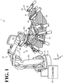
- FIG. 1 is a diagram schematically illustrating a general arrangement of a robot system 1 according to an embodiment.
- FIG. 1 shows a three-dimensional orthogonal coordinate system including a Z axis with its vertically upward direction being assumed the positive direction and the vertically downward direction being assumed the negative direction.
- This orthogonal coordinate system may also be illustrated in some other drawings referred to in the following description.
- a plurality of identical components may occasionally be described by providing a reference numeral to only some of the plurality of identical components, and providing no reference numeral to the rest of the plurality of identical components.
- the some of the plurality of identical components denoted with a reference numeral have the same configuration as the configuration of the rest of the plurality of identical components without a reference numeral.
- a robot system 1 includes a work table 10, a plurality of workpiece supports 20, a robot 30, and a controller 40.
- a workpiece W is placed on the work table 10.
- the workpiece supports 20 are provided in plural to support the workpiece W at a plurality of points on an outer edge of the workpiece W, thereby securing the workpiece W on the work table 10.
- Each of the workpiece supports 20 is movable individually to make a withdrawal so as to avoid contact with a pressure roller 53, described later, while the pressure roller 53 is moving on a motion path along the outer edge of the workpiece W (see an arrow 101 shown in FIG. 1 ). This withdrawal operation is controlled by the controller 40, for example.
- the robot 30 includes a base 31, a rotation base 32, and a robot arm 33.
- the robot arm 33 includes a lower arm 33a, an upper arm 33b, a wrist 33c, and a flange 33d.
- base end side The side of the surface on which the base 31 of the robot 30 is installed will be referred to as "base end side”. A portion of each of the components around the base end side will be referred to as “base end portion”.
- base end portion The flange 33d side of the robot 30 will be referred to as “distal end side”. A portion of each of the components around the distal end side will be referred to as “distal end portion”.
- the base 31 is a supporting base secured on a floor or another surface.
- the rotation base 32 is rotatably disposed on the base 31.
- the lower arm 33a is rotatable relative to the rotation base 32.
- the upper arm 33b is rotatable relative to the lower arm 33a.
- the wrist 33c disposed at the distal end portion of the upper arm 33b in a swingable manner.
- the flange 33d is rotatable relative to the wrist 33c.
- an end effector 50 is mounted to the flange 33d.
- the end effector 50 includes the pressure roller 53.
- the robot arm 33 supports the end effector 50.
- FIG. 2 is a schematic side view of a configuration of the robot 30.
- the robot 30 is what is called a vertical articulated robot.
- the rotation base 32 is coupled to the base 31 in a rotatable manner about a rotation axis S (see an arrow 201 shown in FIG. 2 ).
- the lower arm 33a has a base end portion coupled to the rotation base 32 in a rotatable manner about an axis L, which is approximately perpendicular to the rotation axis S (including a twisted position) (see an arrow 202 shown in FIG. 2 ).
- the upper arm 33b has a base end portion coupled to the distal end portion of the lower arm 33a in a rotatable manner about an axis U, which is approximately parallel to the axis L (see an arrow 203 shown in FIG. 2 ).
- the wrist 33c has a base end portion coupled to the distal end portion of the upper arm 33b in a rotatable manner about an axis R, which is approximately perpendicular to the rotation axis U (including a twisted position) (see an arrow 204 shown in FIG. 2 ).
- the wrist 33c is swingable about an axis B, which is approximately perpendicular to the axis R (see an arrow 205 shown in FIG. 2 ).
- the flange 33d is coupled to the wrist 33c in a rotatable manner about an axis T, which is approximately perpendicular to the axis B (see an arrow 206 shown in FIG. 2 ).
- the robot arm 33 includes joints each having a built-in servomotor, not shown.
- the robot 30 is able to take various postures by controlling the rotation position of the servomotor of each joint.
- the end effector 50 is mounted to the flange 33d. A configuration of the end effector 50 will be described in detail below.
- FIG. 3A is a perspective schematic view of a configuration of the end effector 50.
- FIG. 3B is a schematic view from a direction of the arrow A shown in FIG. 3A .
- the end effector 50 is shown more simply than in FIG. 3A .
- the end effector 50 includes a servomotor 51, a linear motion mechanism 52, and the pressure roller 53.
- the servomotor 51 is a driving source to drive the linear motion mechanism 52 into linear motion.
- the linear motion mechanism 52 is driven by the servomotor 51 to move the pressure roller 53 up and down with respect to the pressed surface of the workpiece W (see an arrow 301 shown in FIG. 3B ).
- the linear motion mechanism 52 preferably includes a ball screw or another element for such considerations as pressure responsiveness.
- the pressure roller 53 is coupled to a linear motion shaft 52a, which is a movable part of the linear motion mechanism 52, in a rotatable manner about an axis AXr.
- the linear motion mechanism 52 brings the pressure roller 53 into contact with the pressed surface of the workpiece W.
- the pressure roller 53 makes rolling movement over the pressed surface while applying the pressing force from the servomotor 51 to the pressed surface.
- the pressed surface is subjected to the pressure processing.
- FIG. 3C is a schematic diagram illustrating an embodiment of the hemming processing.
- Reference numeral W1 shown in FIG. 3C denotes an outer edge portion of an outer panel of a vehicle body.
- Reference numeral W2 shown in FIG. 3C denotes an inner panel of the vehicle body.
- the to-be-processed material will not be limited to a vehicle body; other possible examples include a household appliance.
- the hemming processing starts from "pre-processing" state, proceeds to preliminary bending processing referred to as “pre-hemming”, and proceeds to main bending processing referred to as "hemming".
- pre-hemming preliminary bending processing
- hemming main bending processing
- the outer edge portion W1 of the outer panel is bent by approximately 45° in the pre-hemming, and is bent into an approximately U shape in the hemming and thus joined with the inner panel W2.
- the pressing direction of the pressure roller 53 differs between the "pre-hemming” and "hemming".
- the pressing direction is determined by changing the posture of the robot 30.
- the posture of the robot 30 is changed by controlling the rotation position of each servomotor installed in the robot arm 33, as described above.
- the controller 40 (see FIG. 1 ) performs the operation control of changing the posture of the robot 30.
- the controller 40 not only controls the pressing direction but also controls the pressing force against the pressed surface at the time of "pre-hemming" and "hemming". Specifically, the controller 40 controls the servomotor 51 to make the pressing force of the pressure roller 53 against the pressed surface suitable for the shape of the pressed surface, regardless of a change in shape of the workpiece W. Various kinds of control performed by the controller 40 will be described in detail later by referring to FIG. 5 .
- the linear motion mechanism 52 is controlled through the servomotor 51, as described above. This ensures an elongated stroke length of the linear motion mechanism 52 as compared with the comparative practice to use a fluid cylinder or a similar device.
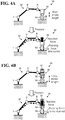
- FIG. 4A schematically illustrates a disadvantage involved in comparative pressure processing.
- FIG. 4B schematically illustrates an advantage involved in the pressure processing according to this embodiment.
- the robot 30 and a robot 30' and their respective components are shown simply using the axes L, U, and B.
- FIG. 4A which shows a comparative technique using an end effector 50' provided with a fluid cylinder or a similar device
- the stroke length is short which can cause the pressure roller 53 to come off the pressed surface, attenuating the pressing force when the robot arm 33' is deflected by reaction force against the pressing force.
- the servomotor 51 drive the linear motion mechanism 52, as shown in FIG. 4B . This ensures a longer stroke length, which prevents the pressure roller 53 from coming off the pressed surface even though the robot arm 33 is deflected by reaction force against the pressing force.
- this embodiment provides an advantage in that the pressing force is maintained at a suitable level, contributing to improving the quality of the hemming processing.
- the use of the servomotor 51 ensures monitoring of the stroke position based on a position detector such as an encoder.
- the servomotor 51 may be controlled to make the pressing force of the pressure roller 53 against the pressed surface of the workpiece W approximately uniform while monitoring the stroke position. This also improves the quality of the hemming processing.
- the controller 40 is coupled in an information transmittable manner to various devices such as the workpiece support 20 and the robot 30. It is noted that any form of connection, wired or wireless, may be employed.
- the controller 40 is a controller to control various operations of the various devices coupled to the controller 40, and includes various control-related devices, a processing unit, and a storage device.
- the controller 40 performs the operation control of changing the posture of the robot 30 based on a "job", which is a predetermined program to bring the robot 30 into operation.
- the job is registered in the storage device or a similar device of the controller 40 through an input device (such as a programming pendant), not shown.
- the controller 40 Based on the "job", the controller 40 generates an operation signal to bring the robot 30 into operation, and outputs the signal to the robot 30.
- the operation signal is generated in the form of a pulse signal to the servomotor installed in each joint.
- FIG. 5 is a block diagram illustrating a configuration of the robot system 1 according to this embodiment. It is noted that FIG. 5 only shows those components necessary for description of the robot system 1, omitting those components of general nature.
- FIG. 5 may occasionally simplify or omit those components already described by referring to FIGs. 1 to 4B .
- the controller 40 includes a control section 41 and a storage section 42.
- the control section 41 includes a program editing section 41a,, an inverse kinematics calculation section 41b, a torque control section 41c, and a position control section 41d.
- the storage section 42 is a storage device such as a hard disk drive and a nonvolatile memory, and stores teaching information 42a.
- the teaching information 42a defines the motion path of the robot arm 33, and is an example of the program storage section.
- the controller 40 shown in FIG. 5 may not necessarily have all its components arranged within the controller 40.
- the teaching information 42a may be stored in the storage section 42, the teaching information 42a may be stored in an internal memory of the robot 30.
- the teaching information 42a may be stored in an upper level device of the controller 40, and may be acquired by the controller 40 from the upper level device as necessary.
- the control section 41 is in charge of overall control of the controller 40. Specifically, the control section 41 controls the linear motion mechanism 52 to move the pressure roller 53 up and down with respect to the pressed surface of the workpiece W so as to make the pressing force of the pressure roller 53 against the pressed surface approximately uniform.
- the program editing section 41a receives settings related to the hemming processing through an input device 60 such as a personal computer (PC) and a programming pendant.
- the settings related to the hemming processing include a setting of starting the operation control of the linear motion mechanism 52 of the end effector 50, and a setting of ending the operation control of the linear motion mechanism 52 of the end effector 50.
- the program editing section 41a reflects the content of the received setting in the program included in the teaching information 42a.
- an operator of the input device 60 may use a macro command to define the setting related to the hemming processing at any timing (step position) on the program. That is, the program editing section 41a includes a preprocessor function that converts the macro command into a program.
- the macro command related to the hemming processing will be hereinafter referred to as "hemming command”.
- FIG. 6 is a diagram illustrating exemplary hemming commands.
- the hemming commands are defined in advance as macro commands related to the torque control and the position control of the servomotor 51.
- No. 1 to No. 3 in FIG. 6 indicate hemming commands related to the torque control for the servomotor 51.
- the command "HEM_ON" at No. 1 is a command for an instruction to start applying pressure at a predetermined torque.
- the command "HEM_OFF” at No. 2 is a command for an instruction to stop applying pressure.
- the command "HEM_CH” at No. 3 is a command to change the pressing force along the motion path.
- the hemming command to change the pressing force may be used in the following exemplary case.
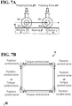
- FIG. 7A is a diagram illustrating the hemming command to change the pressing force.
- the workpiece W may not be uniform throughout the pressed surface in terms of shape, property, or other respects. Assume the example shown in FIG. 7A , where portions of different elasticities exist along the motion path of the pressure roller 53 (see “elasticity ⁇ " and “elasticity ⁇ " shown in FIG. 7A ). Points P1 and P2 shown in FIG. 7A indicate target points on the motion path.
- the command "HEM_CH” may be used to define the program to, for example, make the pressing force suitable for the elasticity of interest. This makes the pressing force applied to the pressed surface approximately uniform.
- the operator uses the command "HEM_CH” to define the program in such a manner that at the timing when the pressure roller 53 is at target point P1, the servomotor 51 effects pressing force ⁇ 1 , which is suitable for elasticity ⁇ .
- the operator uses the command "HEM_CH” to define the program in such a manner that the servomotor 51 effects pressing force ⁇ 1, which is suitable for elasticity ⁇ .
- the command "HEM_PL" at No. 4 is a command for an instruction to switch the torque control to the position control.
- the command “HEM_KP” at No. 5 is a command for maintaining the stroke position of the linear motion mechanism 52.
- FIG. 7B is a diagram illustrating a hemming command related to the position control.
- FIG. 7B there is a workpiece W having a rectangular shape in plan view.
- the workpiece W undergoes the hemming processing on the outer edge of the workpiece W.
- the corners and adjacent portions of the workpiece W which are circled by broken lines in FIG. 7B , are soft and susceptible to elastic deformation.
- the program is preferably defined to perform the position control using the command "HEM_PL". This improves the quality of the hemming processing.
- pre-hemming For the sides of the rectangular workpiece W, excluding the corners, it is preferable in terms of processing quality to maintain the stroke position during pressure application in, for example, "pre-hemming" (see FIG. 3C ).
- the program is preferably defined to maintain the stroke position using the command "HEM_KP".
- HEM_KP the command which is the main bending
- the torque control and the position control are defined at step positions of the program suitable for the shape and property of a portion of the workpiece W or the type of the processing. This improves the quality of the hemming processing.
- the operator is able to recognize the content of the setting related to the hemming processing simply in the form of macro commands, and readily define the hemming commands at any step positions of the program through the input device 60. Thus, the hemming processing is facilitated.
- the inverse kinematics calculation section 41b controls the rotation position of each joint of the robot arm 33 based on the motion path of the robot arm 33, which is taught in advance as the teaching information 42a.
- the inverse kinematics calculation section 41b is in charge of the step of bringing the robot arm 33 into operation.
- the inverse kinematics calculation section 41b regards a coordinate value of a target point on the motion path as the position of a representative point of the end effector 50, and regards the pressing direction at this position as the posture of the end effector 50. Then, the inverse kinematics calculation section 41b generates an operation signal to bring the robot 30 into operation.
- the operation signal is generated as, for example, a pulse signal to the servomotor installed in each joint of the robot arm 33.
- the torque control section 41c controls the torque of the servomotor 51 of the end effector 50 so as to perform the control of making the pressing force of the pressure roller 53 against the pressed surface of the workpiece W approximately uniform. Specifically, the torque control section 41c performs the torque control of the servomotor 51 based on the hemming commands reflected in the teaching information 42a by the program editing section 41a.
- the position control section 41 controls the amount by which the pressure roller 53 protrudes, that is, controls the stroke position of the linear motion mechanism 52. Specifically, the position control section 41d controls the stroke position of the linear motion mechanism 52 by performing the position control of the servomotor 51 based on the hemming commands reflected in the teaching information 42a by the program editing section 41a.
- the position control section 41d monitors the stroke position of the linear motion mechanism 52 based on a detection result obtained by the encoder of the servomotor 51. When the position control section 41d detects an abnormality through the monitoring, the position control section 41d performs predetermined error processing. Thus, the torque control section 41c and the position control section 41d are in charge of the step of the pressure roller 53's control to make the linear motion mechanism 52 move up and down.
- FIG. 8 is a flowchart of a procedure for the processing executed by the robot system 1 according to this embodiment.
- FIG. 8 shows a state in which the program editing section 41a has already reflected in the teaching information 42a the program in which the hemming commands are defined.
- step S101 the teaching information 42a is loaded (step S101).
- the program contained in the teaching information 42a is loaded on a one-step basis.
- the inverse kinematics calculation section 41b controls the rotation position of each joint of the robot arm 33 based on the teaching information 42a (step S102).
- step S103 a determination is made as to whether a hemming command has been issued.
- step S104 the type of the hemming command is determined (step S104).
- the torque control section 41c controls the servomotor 51 to start applying pressure (step S105).
- the torque control section 41c controls the servomotor 51 to stop applying pressure (step S106).
- the torque control section 41c controls the servomotor 51 to change the pressing force (step S107).
- the position control section 41d switches the torque control to the position control (step S108).
- the position control section 41d maintains the stroke position of the linear motion mechanism 52 (step S109).
- step S103 When the determination condition at step S103 is not satisfied (No at step S103), the control proceeds to step S110.
- step S110 a determination is made as to whether the position control section 41d has detected an abnormality through monitoring of the stroke position (step S110).
- a determination is made as to whether the teaching information 42a contains a next program step (step S111).
- step S111 When the teaching information 42a contains the next program step (Yes at step S111), the processing from step S101 on is repeated. When the teaching information 42a does not contain the next program step (No at step S111), the processing ends.
- step S110 When at step S110 an abnormality is detected in the monitoring (Yes at step S110), predetermined error processing is performed (step S 112), and then the processing ends.
- the robot system includes the end effector, the robot arm, and the controller.
- the end effector includes the pressure roller and the linear motion mechanism.
- the linear motion mechanism moves the pressure roller up and down with respect to a pressed surface.
- the robot arm supports the end effector.
- the controller controls the linear motion mechanism to move the pressure roller up and down so as to make the pressing force of the pressure roller against the pressed surface approximately uniform.
- the robot system according to this embodiment ensures readiness and higher quality in the pressure processing.
- the linear motion mechanism is driven by a servomotor.
- a servomotor This facilitates the wiring work in that thinner outfitting cables and other cables may be used as compared with the comparative practice to use a fluid cylinder or a similar cylinder. This, in turn, improves maintenance efficiency and provides no or minimal restriction on the operation of the robot, resulting in improved mobility of the robot.
- the workpiece supports support the workpiece at a plurality of points on the outer edge of workpiece, thereby securing the workpiece on the work table.
- a suction device which is capable of vacuum suction, to secure the workpiece on the work table using the suction device.
- the robot has a single arm with six axes. This, however, should not be construed as limiting the number of axes and the number of arms. Other possible examples include, but are not limited to, a seven-axis robot and a two-arm robot.
Landscapes
- Engineering & Computer Science (AREA)
- Mechanical Engineering (AREA)
- Robotics (AREA)
- Manipulator (AREA)
Applications Claiming Priority (1)
| Application Number | Priority Date | Filing Date | Title |
|---|---|---|---|
| JP2013228184A JP5971226B2 (ja) | 2013-11-01 | 2013-11-01 | ロボットシステムおよび被加工物の製造方法 |
Publications (2)
| Publication Number | Publication Date |
|---|---|
| EP2868403A1 EP2868403A1 (en) | 2015-05-06 |
| EP2868403B1 true EP2868403B1 (en) | 2021-02-17 |
Family
ID=51753019
Family Applications (1)
| Application Number | Title | Priority Date | Filing Date |
|---|---|---|---|
| EP14188736.4A Active EP2868403B1 (en) | 2013-11-01 | 2014-10-14 | Robot system and method for producing to-be-processed material |
Country Status (4)
| Country | Link |
|---|---|
| US (1) | US9908160B2 (ja) |
| EP (1) | EP2868403B1 (ja) |
| JP (1) | JP5971226B2 (ja) |
| CN (1) | CN104608114B (ja) |
Families Citing this family (13)
| Publication number | Priority date | Publication date | Assignee | Title |
|---|---|---|---|---|
| JP6237520B2 (ja) * | 2014-07-24 | 2017-11-29 | 株式会社安川電機 | ロボット |
| JP2016022571A (ja) * | 2014-07-24 | 2016-02-08 | 株式会社安川電機 | ロボットの関節機構およびロボット |
| WO2017134970A1 (ja) * | 2016-02-02 | 2017-08-10 | 本田技研工業株式会社 | ワーク曲げ加工方法及びワーク曲げ加工装置 |
| US20180171448A1 (en) * | 2016-12-20 | 2018-06-21 | United Technologies Corporation | Deep rolling tool and method |
| US20180171447A1 (en) * | 2016-12-20 | 2018-06-21 | United Technologies Corporation | Deep rolling tool and method |
| US10786883B2 (en) | 2016-12-20 | 2020-09-29 | United Technologies Corporation | Deep rolling tool and method |
| JP6734522B2 (ja) * | 2017-05-08 | 2020-08-05 | トライエンジニアリング株式会社 | ロボット装置 |
| CN107413876B (zh) * | 2017-09-26 | 2023-07-07 | 辽宁忠旺集团有限公司 | 一种铝型材压边装置 |
| CN108115706A (zh) * | 2017-12-31 | 2018-06-05 | 芜湖哈特机器人产业技术研究院有限公司 | 一种多轴飞机清洗机器人的控制系统 |
| JP7300663B2 (ja) * | 2019-10-11 | 2023-06-30 | トライエンジニアリング株式会社 | 端末処理装置および端末処理方法 |
| CN113715308B (zh) * | 2021-09-02 | 2022-08-09 | 上海交通大学 | 可调节式多点渐进翻边成形装置及方法 |
| CN113714359B (zh) * | 2021-09-02 | 2022-07-22 | 上海交通大学 | 多道次机器人柔性翻边全模成形方法 |
| US20230415356A1 (en) * | 2022-01-25 | 2023-12-28 | Divergent Technologies, Inc. | Low deflection tooling apparatus |
Citations (1)
| Publication number | Priority date | Publication date | Assignee | Title |
|---|---|---|---|---|
| FR2895690A1 (fr) * | 2006-01-05 | 2007-07-06 | Process Conception Ing Sa | Dispositif d'assemblage de pieces par pliage |
Family Cites Families (19)
| Publication number | Priority date | Publication date | Assignee | Title |
|---|---|---|---|---|
| JPH0716730B2 (ja) * | 1989-01-10 | 1995-03-01 | 日産自動車株式会社 | ヘミング加工装置 |
| JP2693282B2 (ja) * | 1991-03-20 | 1997-12-24 | トライエンジニアリング株式会社 | ローラー式ヘミング装置と該装置を用いたローラー式ヘミング加工方法 |
| EP0577876B1 (en) * | 1992-07-09 | 1996-09-04 | TRIENGINEERING Co., Ltd. | Roller type hemming apparatus |
| JPH0954608A (ja) * | 1995-08-16 | 1997-02-25 | Kawasaki Heavy Ind Ltd | ロボットのシミュレーション方法 |
| JP3215086B2 (ja) * | 1998-07-09 | 2001-10-02 | ファナック株式会社 | ロボット制御装置 |
| US6442451B1 (en) * | 2000-12-28 | 2002-08-27 | Robotic Workspace Technologies, Inc. | Versatile robot control system |
| JP3664089B2 (ja) | 2001-03-13 | 2005-06-22 | トヨタ車体株式会社 | ロールヘミング加工方法 |
| JP3687559B2 (ja) * | 2001-04-06 | 2005-08-24 | トヨタ車体株式会社 | ロールヘミング装置 |
| JP2003103325A (ja) * | 2001-09-26 | 2003-04-08 | Nissan Motor Co Ltd | ロールヘム加工装置およびロールヘム加工方法 |
| JP3623474B2 (ja) * | 2001-10-31 | 2005-02-23 | トライエンジニアリング株式会社 | ヘミング加工装置およびヘミング加工方法 |
| FR2843549B1 (fr) * | 2002-08-13 | 2005-05-27 | Process Conception Ing Sa | Procede et dispositif d'assemblage de pieces par sertissage d'un bord peripherique |
| US7152447B2 (en) * | 2004-03-30 | 2006-12-26 | Tesco Engineering, Inc. | Roller type hemming apparatus |
| JP2006088217A (ja) * | 2004-09-27 | 2006-04-06 | Fuji Heavy Ind Ltd | ロールヘム加工装置 |
| US8015688B2 (en) * | 2006-06-30 | 2011-09-13 | GM Global Technology Operations LLC | Method and apparatus for hemming and sealing a joint |
| JP5111911B2 (ja) * | 2007-03-23 | 2013-01-09 | 本田技研工業株式会社 | ヘミング加工方法及びパネルアセンブリ製造方法 |
| JP5215946B2 (ja) * | 2009-06-12 | 2013-06-19 | 本田技研工業株式会社 | ローラヘミング装置およびローラヘミング方法 |
| JP4795462B2 (ja) * | 2009-11-12 | 2011-10-19 | ファナック株式会社 | 力センサを搭載したロボットマニピュレータを用いたロールヘム加工装置 |
| JP4927927B2 (ja) * | 2009-11-26 | 2012-05-09 | ファナック株式会社 | スポット溶接システム |
| US8640320B2 (en) * | 2011-02-10 | 2014-02-04 | GM Global Technology Operations LLC | Method of joining by roller hemming and solid state welding and system for same |
-
2013
- 2013-11-01 JP JP2013228184A patent/JP5971226B2/ja active Active
-
2014
- 2014-10-14 EP EP14188736.4A patent/EP2868403B1/en active Active
- 2014-10-30 CN CN201410599393.2A patent/CN104608114B/zh active Active
- 2014-10-31 US US14/529,209 patent/US9908160B2/en active Active
Patent Citations (1)
| Publication number | Priority date | Publication date | Assignee | Title |
|---|---|---|---|---|
| FR2895690A1 (fr) * | 2006-01-05 | 2007-07-06 | Process Conception Ing Sa | Dispositif d'assemblage de pieces par pliage |
Also Published As
| Publication number | Publication date |
|---|---|
| CN104608114B (zh) | 2017-04-12 |
| JP2015085485A (ja) | 2015-05-07 |
| US9908160B2 (en) | 2018-03-06 |
| JP5971226B2 (ja) | 2016-08-17 |
| US20150121983A1 (en) | 2015-05-07 |
| EP2868403A1 (en) | 2015-05-06 |
| CN104608114A (zh) | 2015-05-13 |
Similar Documents
| Publication | Publication Date | Title |
|---|---|---|
| EP2868403B1 (en) | Robot system and method for producing to-be-processed material | |
| US10010920B2 (en) | Method to improve geometrical accuracy of an incrementally formed workpiece | |
| JP5382359B2 (ja) | ロボットシステム | |
| JP6055014B2 (ja) | 物または人との接触を検知する機能を有するロボット制御装置 | |
| US8321054B2 (en) | Industrial robot and a method for adjusting a robot program | |
| US8424351B2 (en) | Automated monitoring for clinching joints | |
| JP7122821B2 (ja) | ロボットシステム及びロボット制御方法 | |
| CN102059295A (zh) | 使用装载了力传感器的机器人机械手的辊式卷边加工装置 | |
| TW201641239A (zh) | 彎曲加工裝置 | |
| CA2205162A1 (en) | An operating method for a working area comprising a robot enslaved to a bending press for working metal sheets | |
| US11833687B2 (en) | Robot apparatus, control method for the robot apparatus, assembly method using the robot apparatus, and recording medium | |
| US9764414B2 (en) | Spot welding system and spot welding method | |
| KR20200125727A (ko) | 마찰 접합 장치 및 그 운전 방법 | |
| JP2014151385A (ja) | ロボット制御装置およびロボット制御方法 | |
| JP7015267B2 (ja) | ロボット制御装置及びロボットシステム | |
| CN113858189B (zh) | 机器人的控制方法及机器人系统 | |
| US20210283774A1 (en) | Robot, control device, and information processing device | |
| JP6088601B2 (ja) | 走行軸付きロボットにおけるツール先端の振れを抑制するロボット制御装置 | |
| JP5961077B2 (ja) | ロボット制御装置およびロボット制御方法 | |
| JP5533947B2 (ja) | ロボットシステムおよび嵌合物の製造方法 | |
| JP2017127932A (ja) | ロボット装置、ロボット制御方法、部品の製造方法、プログラム及び記録媒体 | |
| JP2009125840A (ja) | ピアスナット打ち込み装置及びピアスナット打ち込みロボットシステム | |
| JP2009012119A (ja) | ロボットハンド | |
| JP2019155523A (ja) | ロボット制御装置、ロボット制御方法、ロボット制御装置を用いた物品の組立方法、プログラム及び記録媒体 | |
| JP4985135B2 (ja) | 協調ロボットシステム |
Legal Events
| Date | Code | Title | Description |
|---|---|---|---|
| PUAI | Public reference made under article 153(3) epc to a published international application that has entered the european phase |
Free format text: ORIGINAL CODE: 0009012 |
|
| 17P | Request for examination filed |
Effective date: 20141014 |
|
| AK | Designated contracting states |
Kind code of ref document: A1 Designated state(s): AL AT BE BG CH CY CZ DE DK EE ES FI FR GB GR HR HU IE IS IT LI LT LU LV MC MK MT NL NO PL PT RO RS SE SI SK SM TR |
|
| AX | Request for extension of the european patent |
Extension state: BA ME |
|
| R17P | Request for examination filed (corrected) |
Effective date: 20151106 |
|
| RBV | Designated contracting states (corrected) |
Designated state(s): AL AT BE BG CH CY CZ DE DK EE ES FI FR GB GR HR HU IE IS IT LI LT LU LV MC MK MT NL NO PL PT RO RS SE SI SK SM TR |
|
| STAA | Information on the status of an ep patent application or granted ep patent |
Free format text: STATUS: EXAMINATION IS IN PROGRESS |
|
| 17Q | First examination report despatched |
Effective date: 20170105 |
|
| GRAP | Despatch of communication of intention to grant a patent |
Free format text: ORIGINAL CODE: EPIDOSNIGR1 |
|
| STAA | Information on the status of an ep patent application or granted ep patent |
Free format text: STATUS: GRANT OF PATENT IS INTENDED |
|
| INTG | Intention to grant announced |
Effective date: 20200831 |
|
| GRAS | Grant fee paid |
Free format text: ORIGINAL CODE: EPIDOSNIGR3 |
|
| GRAA | (expected) grant |
Free format text: ORIGINAL CODE: 0009210 |
|
| STAA | Information on the status of an ep patent application or granted ep patent |
Free format text: STATUS: THE PATENT HAS BEEN GRANTED |
|
| AK | Designated contracting states |
Kind code of ref document: B1 Designated state(s): AL AT BE BG CH CY CZ DE DK EE ES FI FR GB GR HR HU IE IS IT LI LT LU LV MC MK MT NL NO PL PT RO RS SE SI SK SM TR |
|
| REG | Reference to a national code |
Ref country code: GB Ref legal event code: FG4D |
|
| REG | Reference to a national code |
Ref country code: CH Ref legal event code: EP |
|
| REG | Reference to a national code |
Ref country code: DE Ref legal event code: R096 Ref document number: 602014074783 Country of ref document: DE |
|
| REG | Reference to a national code |
Ref country code: AT Ref legal event code: REF Ref document number: 1360808 Country of ref document: AT Kind code of ref document: T Effective date: 20210315 |
|
| REG | Reference to a national code |
Ref country code: IE Ref legal event code: FG4D |
|
| REG | Reference to a national code |
Ref country code: LT Ref legal event code: MG9D |
|
| REG | Reference to a national code |
Ref country code: NL Ref legal event code: MP Effective date: 20210217 |
|
| PG25 | Lapsed in a contracting state [announced via postgrant information from national office to epo] |
Ref country code: PT Free format text: LAPSE BECAUSE OF FAILURE TO SUBMIT A TRANSLATION OF THE DESCRIPTION OR TO PAY THE FEE WITHIN THE PRESCRIBED TIME-LIMIT Effective date: 20210617 Ref country code: LT Free format text: LAPSE BECAUSE OF FAILURE TO SUBMIT A TRANSLATION OF THE DESCRIPTION OR TO PAY THE FEE WITHIN THE PRESCRIBED TIME-LIMIT Effective date: 20210217 Ref country code: FI Free format text: LAPSE BECAUSE OF FAILURE TO SUBMIT A TRANSLATION OF THE DESCRIPTION OR TO PAY THE FEE WITHIN THE PRESCRIBED TIME-LIMIT Effective date: 20210217 Ref country code: HR Free format text: LAPSE BECAUSE OF FAILURE TO SUBMIT A TRANSLATION OF THE DESCRIPTION OR TO PAY THE FEE WITHIN THE PRESCRIBED TIME-LIMIT Effective date: 20210217 Ref country code: GR Free format text: LAPSE BECAUSE OF FAILURE TO SUBMIT A TRANSLATION OF THE DESCRIPTION OR TO PAY THE FEE WITHIN THE PRESCRIBED TIME-LIMIT Effective date: 20210518 Ref country code: BG Free format text: LAPSE BECAUSE OF FAILURE TO SUBMIT A TRANSLATION OF THE DESCRIPTION OR TO PAY THE FEE WITHIN THE PRESCRIBED TIME-LIMIT Effective date: 20210517 Ref country code: NO Free format text: LAPSE BECAUSE OF FAILURE TO SUBMIT A TRANSLATION OF THE DESCRIPTION OR TO PAY THE FEE WITHIN THE PRESCRIBED TIME-LIMIT Effective date: 20210517 |
|
| REG | Reference to a national code |
Ref country code: AT Ref legal event code: MK05 Ref document number: 1360808 Country of ref document: AT Kind code of ref document: T Effective date: 20210217 |
|
| PG25 | Lapsed in a contracting state [announced via postgrant information from national office to epo] |
Ref country code: PL Free format text: LAPSE BECAUSE OF FAILURE TO SUBMIT A TRANSLATION OF THE DESCRIPTION OR TO PAY THE FEE WITHIN THE PRESCRIBED TIME-LIMIT Effective date: 20210217 Ref country code: NL Free format text: LAPSE BECAUSE OF FAILURE TO SUBMIT A TRANSLATION OF THE DESCRIPTION OR TO PAY THE FEE WITHIN THE PRESCRIBED TIME-LIMIT Effective date: 20210217 Ref country code: RS Free format text: LAPSE BECAUSE OF FAILURE TO SUBMIT A TRANSLATION OF THE DESCRIPTION OR TO PAY THE FEE WITHIN THE PRESCRIBED TIME-LIMIT Effective date: 20210217 Ref country code: LV Free format text: LAPSE BECAUSE OF FAILURE TO SUBMIT A TRANSLATION OF THE DESCRIPTION OR TO PAY THE FEE WITHIN THE PRESCRIBED TIME-LIMIT Effective date: 20210217 Ref country code: SE Free format text: LAPSE BECAUSE OF FAILURE TO SUBMIT A TRANSLATION OF THE DESCRIPTION OR TO PAY THE FEE WITHIN THE PRESCRIBED TIME-LIMIT Effective date: 20210217 |
|
| PG25 | Lapsed in a contracting state [announced via postgrant information from national office to epo] |
Ref country code: IS Free format text: LAPSE BECAUSE OF FAILURE TO SUBMIT A TRANSLATION OF THE DESCRIPTION OR TO PAY THE FEE WITHIN THE PRESCRIBED TIME-LIMIT Effective date: 20210617 |
|
| PG25 | Lapsed in a contracting state [announced via postgrant information from national office to epo] |
Ref country code: SM Free format text: LAPSE BECAUSE OF FAILURE TO SUBMIT A TRANSLATION OF THE DESCRIPTION OR TO PAY THE FEE WITHIN THE PRESCRIBED TIME-LIMIT Effective date: 20210217 Ref country code: EE Free format text: LAPSE BECAUSE OF FAILURE TO SUBMIT A TRANSLATION OF THE DESCRIPTION OR TO PAY THE FEE WITHIN THE PRESCRIBED TIME-LIMIT Effective date: 20210217 Ref country code: CZ Free format text: LAPSE BECAUSE OF FAILURE TO SUBMIT A TRANSLATION OF THE DESCRIPTION OR TO PAY THE FEE WITHIN THE PRESCRIBED TIME-LIMIT Effective date: 20210217 Ref country code: AT Free format text: LAPSE BECAUSE OF FAILURE TO SUBMIT A TRANSLATION OF THE DESCRIPTION OR TO PAY THE FEE WITHIN THE PRESCRIBED TIME-LIMIT Effective date: 20210217 |
|
| REG | Reference to a national code |
Ref country code: DE Ref legal event code: R097 Ref document number: 602014074783 Country of ref document: DE |
|
| PG25 | Lapsed in a contracting state [announced via postgrant information from national office to epo] |
Ref country code: ES Free format text: LAPSE BECAUSE OF FAILURE TO SUBMIT A TRANSLATION OF THE DESCRIPTION OR TO PAY THE FEE WITHIN THE PRESCRIBED TIME-LIMIT Effective date: 20210217 Ref country code: DK Free format text: LAPSE BECAUSE OF FAILURE TO SUBMIT A TRANSLATION OF THE DESCRIPTION OR TO PAY THE FEE WITHIN THE PRESCRIBED TIME-LIMIT Effective date: 20210217 Ref country code: RO Free format text: LAPSE BECAUSE OF FAILURE TO SUBMIT A TRANSLATION OF THE DESCRIPTION OR TO PAY THE FEE WITHIN THE PRESCRIBED TIME-LIMIT Effective date: 20210217 Ref country code: SK Free format text: LAPSE BECAUSE OF FAILURE TO SUBMIT A TRANSLATION OF THE DESCRIPTION OR TO PAY THE FEE WITHIN THE PRESCRIBED TIME-LIMIT Effective date: 20210217 |
|
| PLBE | No opposition filed within time limit |
Free format text: ORIGINAL CODE: 0009261 |
|
| STAA | Information on the status of an ep patent application or granted ep patent |
Free format text: STATUS: NO OPPOSITION FILED WITHIN TIME LIMIT |
|
| 26N | No opposition filed |
Effective date: 20211118 |
|
| PG25 | Lapsed in a contracting state [announced via postgrant information from national office to epo] |
Ref country code: AL Free format text: LAPSE BECAUSE OF FAILURE TO SUBMIT A TRANSLATION OF THE DESCRIPTION OR TO PAY THE FEE WITHIN THE PRESCRIBED TIME-LIMIT Effective date: 20210217 |
|
| PG25 | Lapsed in a contracting state [announced via postgrant information from national office to epo] |
Ref country code: SI Free format text: LAPSE BECAUSE OF FAILURE TO SUBMIT A TRANSLATION OF THE DESCRIPTION OR TO PAY THE FEE WITHIN THE PRESCRIBED TIME-LIMIT Effective date: 20210217 |
|
| PG25 | Lapsed in a contracting state [announced via postgrant information from national office to epo] |
Ref country code: IT Free format text: LAPSE BECAUSE OF FAILURE TO SUBMIT A TRANSLATION OF THE DESCRIPTION OR TO PAY THE FEE WITHIN THE PRESCRIBED TIME-LIMIT Effective date: 20210217 |
|
| REG | Reference to a national code |
Ref country code: CH Ref legal event code: PL |
|
| PG25 | Lapsed in a contracting state [announced via postgrant information from national office to epo] |
Ref country code: IS Free format text: LAPSE BECAUSE OF FAILURE TO SUBMIT A TRANSLATION OF THE DESCRIPTION OR TO PAY THE FEE WITHIN THE PRESCRIBED TIME-LIMIT Effective date: 20210617 |
|
| REG | Reference to a national code |
Ref country code: BE Ref legal event code: MM Effective date: 20211031 |
|
| GBPC | Gb: european patent ceased through non-payment of renewal fee |
Effective date: 20211014 |
|
| PG25 | Lapsed in a contracting state [announced via postgrant information from national office to epo] |
Ref country code: MC Free format text: LAPSE BECAUSE OF FAILURE TO SUBMIT A TRANSLATION OF THE DESCRIPTION OR TO PAY THE FEE WITHIN THE PRESCRIBED TIME-LIMIT Effective date: 20210217 |
|
| PG25 | Lapsed in a contracting state [announced via postgrant information from national office to epo] |
Ref country code: LU Free format text: LAPSE BECAUSE OF NON-PAYMENT OF DUE FEES Effective date: 20211014 Ref country code: GB Free format text: LAPSE BECAUSE OF NON-PAYMENT OF DUE FEES Effective date: 20211014 Ref country code: BE Free format text: LAPSE BECAUSE OF NON-PAYMENT OF DUE FEES Effective date: 20211031 |
|
| PG25 | Lapsed in a contracting state [announced via postgrant information from national office to epo] |
Ref country code: LI Free format text: LAPSE BECAUSE OF NON-PAYMENT OF DUE FEES Effective date: 20211031 Ref country code: CH Free format text: LAPSE BECAUSE OF NON-PAYMENT OF DUE FEES Effective date: 20211031 |
|
| PG25 | Lapsed in a contracting state [announced via postgrant information from national office to epo] |
Ref country code: FR Free format text: LAPSE BECAUSE OF NON-PAYMENT OF DUE FEES Effective date: 20211031 |
|
| PG25 | Lapsed in a contracting state [announced via postgrant information from national office to epo] |
Ref country code: IE Free format text: LAPSE BECAUSE OF NON-PAYMENT OF DUE FEES Effective date: 20211014 |
|
| PG25 | Lapsed in a contracting state [announced via postgrant information from national office to epo] |
Ref country code: HU Free format text: LAPSE BECAUSE OF FAILURE TO SUBMIT A TRANSLATION OF THE DESCRIPTION OR TO PAY THE FEE WITHIN THE PRESCRIBED TIME-LIMIT; INVALID AB INITIO Effective date: 20141014 |
|
| PG25 | Lapsed in a contracting state [announced via postgrant information from national office to epo] |
Ref country code: CY Free format text: LAPSE BECAUSE OF FAILURE TO SUBMIT A TRANSLATION OF THE DESCRIPTION OR TO PAY THE FEE WITHIN THE PRESCRIBED TIME-LIMIT Effective date: 20210217 |
|
| PGFP | Annual fee paid to national office [announced via postgrant information from national office to epo] |
Ref country code: DE Payment date: 20230830 Year of fee payment: 10 |
|
| PG25 | Lapsed in a contracting state [announced via postgrant information from national office to epo] |
Ref country code: MK Free format text: LAPSE BECAUSE OF FAILURE TO SUBMIT A TRANSLATION OF THE DESCRIPTION OR TO PAY THE FEE WITHIN THE PRESCRIBED TIME-LIMIT Effective date: 20210217 |